DISTRIBUTED TRAFFIC CONTROLLING SYSTEM AND METHOD FOR NETWORK DATA
CROSS-REFERENCE TO RELATED APPLICATIONS
This application is a continuation of U.S. Patent Application Serial No. 09/437,637
entitled "Distributed Traffic Controller for Network Data", filed November 10, 1999, which
is incorporated herein by reference.
BACKGROUND OF THE INVENTION
1. Field of the Invention
This invention relates to computer network data traffic and, more particularly, to
controllers that manage the flow of data in a computer network.
2. Description of the Related Art
To enable sharing of data among computer users, most computer systems in use today
are connected to a computer network. Computers in an office, for example, may be
connected over a local area network (LAN) to gain access to a server computer, which
manages common data storage. The Internet is a computer network in which literally
millions of user computers communicate with server computers over a widely distributed
network. The server computers may be file servers that provide data files in response to user
requests, or they may perform other functions, such as e-mail processing.
Data traffic over the Internet generally follows a transportation protocol called the
Transport Control Protocol/Internet Protocol (TCP/IP). Some of the data traffic involves user
data messages that are sent from users over the network through routers and switches to
destination computers. The destination computer may be a server computer, such as where
an Internet user requests a page from a web site. In that case, a user sends a request message
to a web server computer in accordance with a hypertext transfer protocol (HTTP). The
request is received at the web server computer, which returns the web site data over the
Internet network to the requesting user computer. Instead of a server computer, the
destination computer may be another user, such as where an Internet user sends an e-mail
message over the Internet to another user. In that case, a user sends an e-mail message to an
outgoing mail server computer, which sends the message out over the Internet to an
appropriate destination e-mail server, which then routes the message to the appropriate user
computer.
Because the Internet is a public data network, there is no way to reliably ensure the
integrity of data traffic being routed over the Internet. That is, so-called "hackers" may be
sending computer viruses to randomly targeted destinations, or hackers may attempt to gain
access to a web server computer to alter or destroy the data stored there. To protect against
such malicious acts, firewall systems have been developed to screen out unwanted traffic and
to protect against unauthorized intrusions.
Figure 1 shows a conventional firewall system 100 in which a single firewall machine
102 acts as a secure gateway between the Internet 104 or other public network and two local
user networks 106, 108. All traffic to and from the outside world (the Internet) must pass
through the firewall machine 102. In accordance with TCP/IP addressing, Internet traffic
views the address of the system 100 through an external subnet address, which in the Figure
1 system is illustrated as the external subnet of (200.199.198.0). In this document, network
addresses will be enclosed within parentheses, whether for subnets or individual host
machines. Those skilled in the art will understand that the firewall machine 102 will have a
machine address that is an address under the external subnet. In particular, the address of
(200.199.198.1) is shown in Figure 1 as the address, or Uniform Resource Locator (URL) of
the firewall machine 102. Similarly, the two local networks 106, 108 are shown connected to
the firewall machine 102, the first subnet 106 shown as the (192.168.1.0) subnet and the
second subnet 108 shown as the (192.168.2.0) subnet.
To implement the firewall processing, the gateway computer 102 is loaded with
firewall software programming, as well as being configured with network interfaces to each
internal and external subnet 106, 108. Such firewall software is readily available and may
comprise, for example, the "FireWall-1" product from Check Point Software Technologies
Ltd. of Redwood City, California, USA.
The firewall machine 102 will have multiple Internet protocol (LP) addresses, one for
each subnet. Because there is a single firewall machine, all client machines and routers of the
local networks 106, 108 can simply specify the IP address of the firewall machine 102 as
their default gateway for all outgoing data traffic destined for the Internet. This firewall
implementation provides a simple and relatively inexpensive solution to ensuring integrity of
the local networks on the "downstream" side of the gateway 102. Unfortunately, the single
gateway is a single point of failure and can become a potential bottleneck for data traffic.
This likely will be become more and more critical as firewall machines are asked to perform
more and more tasks, such as encryption and authentication. That is, whenever the firewall
machine 102 is not functioning, all of the internal, local network machines are isolated from
the outside world via the Internet. The single bottleneck can be a serious problem, because
even simple maintenance and upgrades on the firewall machine will be necessary from time
to time, and when they occur, they will result in network downtime that will isolate the client
side machines from the Internet. For many web sites, such as e-commerce sites, no amount
of downtime is acceptable.
Conventionally, increased availability and reduced network downtime is provided by
multiple gateway machines. In the system 200 shown in Figure 2, a multiple gateway system
is provided to the Internet 202 that is comprised of multiple firewall machines 204, 206, 208,
210. Rather than a single IP address, the gateway is identified by a single external subnet
(200.199.198.0) and with an associated set of IP addresses, comprising an address pool, off
that subnet and corresponding to each of the firewall machines 204, 206, 208, 210,
respectively. For example, the addresses may comprise the set of (200.199.198.1),
(200.199.198.2), (200.199.198.3), and (200.199.198.4).
In Figure 2, each firewall machine 204, 206, 208, 210 is connected to two internal
subnets, a first subnet 212 and a second subnet 214. Each of these internal subnets, which are
local networks, can be connected to multiple local computers 216, 218, 220, such as web
server or e-mail server computers. Each computer connected to either one of the internal
subnets 212, 214 must select one IP address from a corresponding pool of subnet IP
addresses as their default gateway address.
For example, the first subnet 212 is indicated as the (192.168.1.0) subnet, and may be
associated with a pool of IP addresses comprising (192.168.1.1), (192.168.1.2),
(192.168.1.3), and (192.168.1.4) addresses. Therefore, a web server 216 connected to the
first subnet 212 can select either one of these four IP pool addresses as its default gateway
computer for handling upstream data traffic. The second subnet 214 is indicated as the
(192.168.2.0) subnet, and is shown as having an IP address pool comprising (192.168.2.1),
(192.168.2.2), (192.168.2.3), and (192.168.2.4) addresses. Therefore, a web server 220
connected to the second subnet 214 can select either one of these second subnet IP addresses
as its default gateway computer for handling upstream data traffic.
In the Figure 2 system 200, if there is a failure of any gateway machine 204, 206, 208,
210 or of any network interface or software at a firewall machine, then all local network
machines and routers configured to use that machine as their default gateway will lose their
connection to the outside world. For example, if the web server computer 216 is configured
to use the first subnet firewall machine 204 as its default gateway, and if there is a failure
with that machine, then the web server 216 will lose communication with the outside world,
even though there are still three remaining firewall machines 204, 206, 208 that might be able
to handle data traffic from that web server. Thus, whenever a failure occurs, some local
network users will be out of communication. The multiple firewall machine implementation
shown in Figure 2 therefore relieves the operational bottleneck problem described above by
providing additional resources for handling data traffic, but cannot provide high availability
in the case of machine failures.
From the discussion above, it should be apparent that there is a need for controlling
data traffic over a network so as to provide firewall protection, relieve operational
bottlenecks, and increase network availability. The present invention solves this need.
SUMMARY OF THE INVENTION
In accordance with the invention, a distributed gateway for computer network data
traffic dynamically reconfigures traffic assignments among multiple machines for increased
network availability. If one of the distributed gateway machines becomes unavailable, traffic
assignments are moved among the multiple machines such that network availability is
substantially unchanged. The machines of the distributed gateway form a cluster and
communicate with each other such that automatic, dynamic traffic assignment
reconfiguration occurs in response to machines being added and deleted from the cluster,
with no loss in functionality for the gateway overall, in a process that is transparent to
network users, thereby providing a distributed gateway functionality that is scalable. Thus,
operation of the distributed gateway remains consistent as machines are added and deleted
from the cluster. Each machine of the distributed gateway can continue with any applications
it may be running, such as firewall software, while participating in the distributed gateway
and dynamic reconfiguration processing of the present invention. In this way, the invention
substantially maintains network availability regardless of machine failures, so that there is no
single point of failure and no lapse in gateway functionality.
In one aspect of the invention, the machines of the distributed gateway cluster
communicate with each other by passing a Group Membership protocol word among the
cluster machines over the subnet network with which they are connected. The protocol word
is used to inform the distributed gateway machines of the cluster status, including the status
of individual machines, in a token ring arrangement. Thus, each machine of the cluster
becomes aware of any problem with any of the other machines in the cluster and is aware of
the operational status of each machine. With such knowledge, the machines will individually
determine the traffic load being borne by the other machines. If any one machine observes
that another machine is handling an excessive amount of network traffic, the observing
machine will take on some of the traffic from the overloaded machine, thereby performing a
load balancing operation.
In another aspect of the invention, a user can configure and monitor a machine of the
distributed gateway cluster from any other machine of the cluster, and also can perform such
configuration and monitoring from a remote location. Such operations can be conducted
through a command line interface or through a graphical user interface (GUI) that permits
real time changes in network IP address assignments.
In another aspect of the invention, a scalable, distributed, highly available, load
balancing network server system is provided, having multiple machines that function as a
front server layer between the network and a back-end server layer having multiple machines
functioning as Web file servers, FTP servers, or other application servers. The front layer
machines comprise a server cluster that performs fail-over and dynamic load balancing for
both server layers. The operation of the servers on both layers is monitored, and when a
server failure at either layer is detected, the system automatically shifts network traffic from
the failed machine to one or more of the remaining operational machines, reconfiguring
front-layer servers as needed without interrupting operation of the servers. The server system
automatically accommodates additional machines in the server cluster, without service
interruption. A system constructed in accordance with the invention provides a front layer
server cluster that manages multiple network addresses and ensures availability of all
network addresses assigned to the front layer at all times. The system operates with a
dynamic reconfiguration protocol that permits reassignment of network addresses to the front
layer machines. The server cluster may manage network address assignments and route
network traffic, operating as a gateway, providing management of virtual network addresses
such that network address assignments can be moved from gateway to gateway without
requiring rebooting. Finally, the system provides symmetric routing of network traffic,
guaranteeing that the incoming and outgoing traffic of the same network connection goes
through the same front-layer server.
Other features and advantages of the present invention should be apparent from the
following description of the preferred embodiment, which illustrates, by way of example, the
principles of the invention.
BRIEF DESCRIPTION OF THE DRAWINGS
Figure 1 is a schematic diagram of a prior art computer system in which a single
firewall computer controls the flow of data traffic from a network to local network
computers.
Figure 2 is a schematic diagram of a prior art computer system in which multiple
firewall computers control the flow of data traffic from a network to local network
computers.
Figure 3 is a schematic diagram of a computer system constructed in accordance with
the present invention.
Figure 4 is a representation of a gateway computer in Figure 3, illustrating the OSI
networking model components of the gateway constructed in accordance with the present
invention.
Figure 5 is a representation of the system architecture for the Application Wrapper
illustrated in Figure 4.
Figure 6 is a block diagram of a gateway computer in the system of Figure 3,
illustrating the hardware components of the computer.
Figure 7 is a representation of the Group Membership protocol word used by the
distributed gateway computer of Figure 4 in communicating status information in the
computer system of the invention.
Figure 8 is a flow diagram of the operating steps executed by a distributed gateway
computer of Figure 3 in starting up and processing group membership messages on a subnet
of the system.
Figure 9 is a flow diagram that shows details of the group membership message
processing performed by each of the distributed gateway computers of Figure 3.
Figure 10 is a representation of a GUI setup screen as shown on the display device of
the Figure 6 computer, in accordance with the present invention, for setting up primary IP
addresses.
Figure 11 is a representation of a GUI setup screen as shown on the display device of
the Figure 6 computer, in accordance with the present invention, for setting up virtual IP
addresses.
Figure 12 is a representation of a GUI screen as shown on the display device of the
Figure 6 computer, in accordance with the present invention, for a Remote Management
Console screen for running the distributed gateway cluster from a remote computer.
Figure 13 is a representation of the Remote Management Console screen of Figure 12,
showing the Edit menu for entry of cluster configuration data.
Figure 14 is a representation of a token message train, sent by the distributed gateway
servers illustrated in Figure 3.
Figure 15 is a flow diagram that shows the operating process of a distributed gateway
in the system of Figure 3 to provide IP address reassignment without server OS rebooting.
Figure 16 is a flow diagram that shows the operation of a distributed gateway in the
system of Figure 3 to provide symmetric routing of traffic through the gateway server cluster.
Figure 17 is a schematic block diagram that illustrates the data traffic in the server
cluster operation according to Figure 16.
DESCRIPTION OF THE PREFERRED EMBODIMENTS
Figure 3 is a representation of a computer system 300 constructed in accordance with
the present invention. A system constructed in accordance with the present invention is set
up to include at least two computers acting as a distributed traffic control center, or gateway,
between two networks. The Figure 3 system 300 includes four machines 302, 304, 306, 308
that act as a distributed gateway 310 between an external subnet 312 interface to the Internet
314 and two internal subnets 316, 318. The four machines control network traffic to and
from the internal subnets. The four machines can dynamically reconfigure traffic
assignments among themselves and provide increased network availability. For example, if
one of the machines 302, 304, 306, 308 becomes unavailable, traffic assignments are moved
among the remaining machines such that network availability to host machines on the
internal subnets 316, 318 is substantially unchanged. In the illustrated embodiment of Figure
3, the external network is the Internet, and therefore the data traffic being handled by the
gateway 310 follow the TCP/IP protocol model, but it should be understood that other
network protocols may be accommodated by a distributed gateway constructed in accordance
with the invention, without departing from the teachings of the invention.
As described further below, the machines 302, 304, 306, 308 of the distributed
gateway 318 communicate with each other such that dynamic traffic assignment
reconfiguration occurs automatically in response to any machine being added or deleted from
the gateway 310, with no loss in functionality for the gateway. The reconfiguration process
is transparent to local network users, thereby providing a distributed gateway functionality
that is scalable. Each machine of the gateway may implement an operational function, such
as web server, e-mail server, or encryption services, and can continue with its operational
functions while it participates in the distributed gateway and dynamic reconfiguration
processing. In this way, the invention substantially maintains network availability regardless
of machine failures, so that there is no single point of failure and no lapse in gateway
functionality.
Each machine 302, 304, 306, 308 of Figure 3 is associated with an Internet protocol
(LP) address that uniquely identifies the machine and provides an address that is associated
with a network interface card (NIC) of the respective machine. This IP address, which is
associated with a physical resource such as the NIC, will be referred to as a primary (or
physical) IP address, and is an address off of the respective subnet 316, 318. Those skilled in
the art will understand that each of the machines includes a NIC interface for each network
(internal and external) to which the machine is connected.
In accordance with the invention, the machines 302, 304, 306, 308 provide a
distributed gateway by maintaining a set of dynamically assignable IP addresses for each
subnet 312, 316, 318. The set of assignable IP addresses for each subnet is called a virtual IP
pool. Each subnet 312, 316, 318 in Figure 3 is identified with a respective virtual IP pool
322, 324, 326. Software that provides the distributed gateway functionality is installed in
each of the machines 302, 304, 306, 308. Thus, in Figure 3, each one of the gateway
machines includes three NIC interfaces, for connection of the respective machine to the
external subnet 312 and the two internal subnets 316, 318, and each of the machines is
associated with a primary IP address and with a virtual IP address for each subnet.
Because of the distributed gateway software installed at each machine, users or host
machines on both sides of the gateway 310 will know of and will direct data packets to an
address in one of the virtual IP pools, rather than the primary LP address associated with each
gateway machine. Thus, a router 320 that directs data traffic to the computers behind the
gateway 310 will be aware of only the IP addresses in the virtual LP pool 322 on the external
subnet and will not be aware of the primary IP addresses assigned to the NIC cards of each
respective gateway machine 302, 304, 306, 308. Similarly, the internal host machines 330,
332, 334 behind the gateway 310 will be aware of only the LP addresses in the virtual IP
pools 324, 326 on the respective internal subnets 316, 318 and will not be aware of the
primary IP addresses assigned to the NIC cards in the gateway machines for each connection
to an internal subnet.
As described more fully below, the dynamic assignment of virtual IP addresses to
primary IP addresses permits reconfiguration in response to machine problems and in
response to variations in network traffic loading among the machines. If a gateway machine
becomes unavailable, then the virtual IP address (or addresses) for which it was responsible
are simply assigned to one or more different gateway machines. This capability is referred to
as a fail-over capability. A related feature is the scalability of the system, such that the
system automatically reconfigures itself dynamically as machines are added or deleted. This
also permits more efficient workload distribution among the gateway machines. If a gateway
machine becomes heavily burdened with data traffic, one or more of the virtual IP addresses
assigned to it will instead be assigned to one or more different gateway machines.
System Software Components
Figure 4 is a representation of a gateway computer in Figure 3, illustrating the system
architecture 400 of the gateway constructed in accordance with the present invention. Those
skilled in the art will understand that Figure 4 is a system architecture representation in terms
of the Open Systems Interconnection (OSI) networking model published by the International
Standards Organization.
The lowest level of the system architecture is the Physical layer, Layer 1 , where data
packets are received at a cable connection 402 from the distributed gateway machine to a
subnet, which in the prefeπed embodiment typically comprises an Ethernet peer-to-peer
network. The next OSI level is the Data Link layer, which packages data bits received from
the physical layer into data frames that are processed by the higher layers. The Data Link
layer is responsible for providing an eπor-free transmission of data frames between
computers through the Physical layer. For example, data packets in the gateway machine are
physically received at a network interface card (NIC) of the gateway from a network cable
connection. Figure 4 shows the data link layer function being performed by a NIC Driver
404, which may be a conventional driver program for processing data traffic received in
accordance with the Ethernet protocol, or whatever protocol is used for the associated subnet
with which the NIC communicates.
The Network layer of the OSI system model is responsible for addressing messages
and translating logical addresses into physical addresses. This layer determines which path
data will take from a source computer to a destination computer. In Figure 4, the Network
layer is occupied by the Application Wrapper Driver 406 and the Application Driver 408.
The Application Wrapper Driver refers to the driver for the application wrapper software that
provides the distributed gateway functionality of the present invention. The Application
Driver refers to the driver for the application software with which the gateway machine
operates. For example, the distributed gateway may be operated in conjunction with firewall
software, to provide a distributed firewall gateway. Alternatively, the application software
may comprise an e-mail server, in which case the invention provides a distributed mail server
with extremely high availability. Other application software may work with the distributed
gateway software of the invention to provide the desired gateway functionality.
The next layer in the OSI model is the Transport layer, which in Figure 4 is
represented by the TCP/IP stack 410. The Transport layer repackages messages so as to
avoid eπors and ensure data is in the proper sequence. The details of this OSI layer in
general, and the TCP/IP functioning in particular, will be well understood by those skilled in
the art. In the Application/Presentation layer, the distributed gateway of the invention
includes the Application Wrapper 412 and the Application 414 software. The Application
module 414 refers to software that performs conventional functions, in concert with the
distributed functionality of the present invention. For example, the Application module may
provide firewall processing, e-mail services, or web page server functionality. As noted
above, the Application Wrapper 412 is the software that provides the distributed gateway
functionality in accordance with the invention, while the Application is the operational
software whose functionality is enhanced, so as to be scalable and distributed, by the
Application Wrapper software.
Figure 5 shows details of the Application Wrapper 410 to better illustrate the
architecture of the distributed gateway. One component function of the Application Wrapper
is the Virtual LP Address module 502, which maintains the virtual-to-primary LP address
mapping between the primary addresses and the virtual IP address pool. Consistent State
Sharing 504 is a module that permits the gateway machines to know which machines are
functioning and which virtual IP addresses have been assigned to each of the machines. The
Reliable Communication 506 component tracks acknowledgment messages communicated
around the gateway, and also helps implement Group Membership Management 508, which
keeps track of the available machines. Network operations are monitored by the Global Fault
Monitor 510, which is complemented by a Local Fault Monitor 512 for the particular
machine on which the Application Wrapper is running. A Local Load Monitor 514
determines the data flow rate through the NIC interface in bytes to keep track of machine
loading. The Dynamic Load Balancing 516 ensures that no single gateway machine becomes
overloaded. It does this by moving virtual LP address assignments, if necessary, in view of
the monitored local loads. The Transparent Fail-Over 518 ensures that a failed machine is
quickly replaced with an alternative machine, thereby providing high availability in a manner
that is transparent to users. These functions operate in conjunction with overall Network
Management tasks 520 performed by the gateway software.
Computer Construction
Figure 6 is a block diagram of a gateway computer in the system of Figure 3,
illustrating the hardware components for one of the computers. Those skilled in the art will
appreciate that the gateway computers 302, 304, 306, 308 and the internal host computers can
all have a similar computer construction.
Figure 6 is a block diagram of an exemplary computer 600 such as might comprise
any of the computers 302, 304, 306, 308. Each computer 600 operates under control of a
central processor unit (CPU) 502, such as a "Pentium" microprocessor and associated
integrated circuit chips, available from Intel Corporation of Santa Clara, California, USA. A
computer user can input commands and data from a keyboard 504 and can view inputs and
computer output at a display 606. The display is typically a video monitor or flat panel
display. The computer 600 also includes a direct access storage device (DASD) 607, such as
a hard disk drive. The memory 408 typically comprises volatile semiconductor random
access memory (RAM). Each computer preferably includes a program product reader 610
that accepts a program product storage device 612, from which the program product reader
can read data (and to which it can optionally write data). The program product reader can
comprise, for example, a disk drive, and the program product storage device can comprise
removable storage media such as a magnetic floppy disk, a CD-R disc, a CD-RW disc, or
DVD disc. Each computer 600 can communicate with the others over the network through a
network interface 614 that enables communication over a connection 616 between the
network and the computer. The network interface typically comprises, for example, a
Network Interface Card (NIC) that permits communications over a variety of networks. In
the gateway 310 (Figure 3), the network can comprise an Ethernet network or can comprise a
connection to the Internet.
The CPU 602 operates under control of programming steps that are temporarily stored
in the memory 608 of the computer 600. When the programming steps are executed, the
Distributed Gateway machine performs its functions. Thus, the programming steps
implement the functionality of the distributed system architecture modules 100 illustrated in
Figure 5. The programming steps can be received from the DASD 607, through the program
product storage device 612, or through the network connection 616. The storage drive 610
can receive a program product 612, read programming steps recorded thereon, and transfer
the programming steps into the memory 608 for execution by the CPU 602. As noted above,
the program product storage device can comprise any one of multiple removable media
having recorded computer-readable instructions, including magnetic floppy disks and CD-
ROM storage discs. Other suitable program product storage devices can include magnetic
tape and semiconductor memory chips. In this way, the processing steps necessary for
operation in accordance with the invention can be embodied on a program product.
Alternatively, the program steps can be received into the operating memory 608 over
the network 314. In the network method, the computer receives data including program steps
into the memory 608 through the network interface 614 after network communication has
been established over the network connection 616 by well-known methods that will be
understood by those skilled in the art without further explanation. The program steps are
then executed by the CPU to implement the processing of the Distributed Gateway system.
It should be understood that all of the computers 302, 304, 306, 308 of the computer
system illustrated in Figure 3 have a construction similar to that shown in Figure 6, so that
details described with respect to the Figure 6 computer 600 will be understood to apply to all
computers of the system 300. Alternatively, any of the computers 302, 304, 306, 308 can
have an alternative construction, so long as they can communicate with the other computers
and support the functionality described herein.
Group Membership Protocol Word
The fail-over operation, scalability of the system, assignments of virtual IP (VIP)
addresses to machines, and the ability to dynamically reconfigure such assignments, are
achieved with the distributed gateway software through a Group Membership protocol word
that provides state sharing information among all the machines in a cluster. The state-sharing
protocol word is passed around the cluster machines who are members of the same subnet in
a token ring arrangement that will be familiar to those skilled in the art.
Figure 7 is a representation of the Group Membership state protocol word 700 that is
used by the cluster computers of Figure 6 in communicating the state information among the
machines of the distributed gateway. The state protocol word 700 includes a Signal Type
(SIG) field 702 that indicates whether the word is a token message for normal operating
conditions or is a notification message (also called a "911" message). The next field is a
Sequence (SEQ.) field 704 that is incremented by each node as the message makes its way
around the nodes of the cluster. The next field is a Membership field 706 that indicates the
group composition of the cluster, followed by a VIP list and assignments field 708 (Group
Composition) to reflect cluster configuration data, and finally there is an Operational Data
field containing load and byte count data 710 that indicates the data flow rate through a node.
In particular, the data flow rate is indicated by information retrieved from the NIC of the
node. Each received Group Membership message, whether it is a normal token message or a
"911" message, is parsed by the distributed gateway software of each particular cluster
machine to extract the necessary data.
The Sequence number field 704 is incremented by each node when it receives a
message (a token message or 911 message). An initial random sequence number is selected
as a default start value, and when the sequence numbering reaches a predetermined limit
value, the sequence numbering wraps around and begins at the start value. When a node puts
a message on the subnet, the node increments the sequence number that was contained in the
received token, places the incremented token back out on the subnet, and stores the
incremented number in memory. Thus, any message produced by a node will have a unique
sequence number. A node should not receive a token message with a sequence number lower
than the sequence number stored in its memory.
The Membership field 706 in a token message is a collection of sub-fields to indicate
group composition. In particular, the Membership field of the prefeπed embodiment
contains data that provides the number of nodes in the cluster, a list of the nodes, the cuπent
node sending the token message, and the destination node (the next node in the cluster, the
node to whom the message is being sent). Each node changes the appropriate membership
field values when the node receives the token, and in this way ensures that the token is passed
along the machines in the cluster, from node to node in proper sequence.
For example, the "number of nodes" field in a token message might indicate a cluster
having four nodes, such as illustrated in Figure 3. The token message might indicate subnet
addresses of (1.1.1.1), (1.1.1.2), (1.1.1.3), and (1.1.1.4) in the "list of nodes" data of the
Membership field 706. If the nodes are numbered, from first to last, as -1, -2, -3, and -4, and
if, at a particular point in time, the token is being sent from the second node (node -2) and is
received at the third node (-3), then the "current node" value is "2" (the second node in the
cluster) and the "destination node" value is "3" (the third node). After the third node (-3)
receives the token, the third node changes the "current node" to "3", changes the destination
node to "4", and sends the token back out on the subnet to the next node. In this way, each
node always knows whether it is the intended recipient of a token message.
The Membership field 706 in a "911" message includes two sub-fields comprising an
originating node address and a permission flag. A "911" message is sent by a node (the
"originating node") when that node determines that the token message might have been lost
somewhere in the cluster, and therefore might need to be regenerated. This may occur, for
example, if another node fails when it has possession of the token message for processing. In
that case, the originating node needs to determine if it has the latest copy of the token to
regenerate the token. This determination is made with the help of the "911 " message.
As a "911 " message is sent around the machines of a distributed gateway cluster, the
permission flag value in the message is set to TRUE by each node when it receives the "911"
message, unless a receiving node has a higher sequence number stored in its memory for the
last token message it sent out. If the receiving node has a higher sequence number, then it
sets the permission flag to FALSE before putting the "911" message back out on the subnet.
When the originating node receives back the "911" message, it will examine the message to
determine if the permission flag sub-field contains TRUE or FALSE. If the permission flag
is FALSE, then the originating node will not regenerate the token message it has in memory.
That is, when the "911" message received by the originating node says FALSE, that means
another node has already sent out a more recent token, with a higher sequence number.
Therefore, the originating node will wait for the next token message (having a higher
sequence number), and will adopt the system values (VLP list, membership, etc.) that are
indicated in that token. If the originating node receives a "911" message back with TRUE,
then the originating node knows it has the most recent token, so it will re-send the last token
message it has, with all its system values (VIP list, membership, etc.). The unique sequence
number ensures that only one node, the one with the most recent token message, will change
the permission flag to TRUE.
The Group Composition field 708 of the Group Membership protocol word 700
contains a list of virtual IP addresses (VIP list) and of corresponding node assignments for
those addresses. The Group Composition field contains sub-fields of data that specify the
VIP address, the primary IP address to which that VIP address is cuπently assigned, an
indication for each VIP address whether there is a preference for assignment to that address,
and a persistence or "sticky" flag to indicate whether the preference is sticky. A sticky VIP
address assignment means that the VIP address will be forced to an assignment to that
particular node, so that all traffic for that VIP address must be directed to that node, unless
the machine is unavailable. Thus, a sticky assignment in the Membership field means that all
data traffic for that node will be directed to that node, if the node is available. If the node
fails, traffic will be re-routed. If the node comes back up, then the data traffic intended for
the node will again be directed to that node. A persistence flag set to a non-zero value
indicates that a user has indicated a preference for assigning that VLP address to the node
involved.
For example, if there are four addresses in the V P list, then the information in the
Group Composition field 708 might be summarized in Table 1 below:
Table 1.
As Table 1 shows, the Group Composition field 708 contains four sub-fields: VIP
address, Cuπent Host, Prefeπed Host, and Persistence Flag. Each of the first three fields
holds the value of an IP address. The last field is an integer. In the prefeπed embodiment,
data in the Group Composition field 708 will be placed in sequence, so that data for the first
row of Table 1 is listed in the Group Composition field, followed by data for the second row,
and so forth. Other schemes for packing the Group Composition field may be used.
In the Group Composition data, there is one VIP address sub-field, providing a VIP
list for the entire cluster. The first sub-field, VIP address, lists the VIP addresses for the
entire distributed gateway cluster. The second sub-field, Current Host, specifies which node
currently owns this particular VIP address. The primary LP address of that node is used in the
Current Host value. For example, according to Table 1, node (1.1.1.5) owns, or is assigned,
VLP addresses (1.1.1.1) and (1.1.1.2). The third sub-field, Prefeπed Host, indicates the node
at which this VLP prefers to be hosted. For example, to move VLP address (1.1.1.1) from
Node (1.1.1.5) to Node (1.1.1.6), it would be necessary to specify Current Host as (1.1.1.5),
and Prefeπed Host as (1.1.1.6). The VLP address assignments indicated by the Cuπent Host
and Prefeπed Host data sub-fields can be changed by a user during real-time operation of the
distributed gateway application through a user interface, which is described in greater detail
below.
The last sub-field of the Group Composition data is the Persistence Flag. It indicates
whether the associated VIP address is "sticky" to the Prefeπed Host. When a VLP address is
"sticky" to an assigned node (the one it is associated with in the same row of Table 1), it is no
longer handled by the load balancing process of the distributed gateway application wrapper.
The Persistence Flag field can take three possible integer values: "0", "1" and "3". When it
is "0", it means that the associated VIP address is not sticky to any node. This VIP address
can be moved, if so required by the load balancing process. When the Persistence Flag is
"1", it means this VIP address is sticky to the Cuπent Host specified in the same row of
Table 1, and therefore it is not handled by the load balancing process. If the Cuπent Host
fails, this VIP address assignment will move to another node of the subnet, and will become
sticky to that node. It will stay on that node even if the original Host recovers. When the
Persistence Flag is "3", it means this VLP address is sticky to the Prefeπed Host.
Whenever the Prefeπed Host is functioning (alive), the VIP address will move to the
Prefeπed Host node and stay with it (becomes "sticky" to it). When the Preferred Host fails,
it fails over to another node of the subnet. The VLP address will move back to the Prefeπed
Host when the Prefeπed Host recovers. It should be noted that regardless of which value the
Persistence Flag takes, when the Cuπent Host fails, the associated VLP address will always
fail over to a healthy (alive) node. As described further below, the "sticky" feature of a VIP
address assignment can be changed by a user in real time through a system interface.
Returning to Figure 7, the last data field of the protocol word 700 is the load and byte
count data field 710. This data field indicates the traffic flow of message packets through
each of the distributed gateway machines of the cluster subnet. In the prefeπed embodiment,
the data comprises a byte count of data through the network interface card that connects each
distributed gateway machine to the subnet. As with the group composition field 708, the byte
count field 710 is organized in the protocol word such that the data for the first node occurs
first, then the second node, then the byte count data for the third node, and so forth for each
of the machines in the cluster who are connected to the pertinent subnet.
In accordance with the invention, the protocol word 700 is circulated around the
subnet from machine to machine, in sequence. Each machine receives a protocol word as
part of the group membership message that is passed from machine to machine
approximately at a rate of once every 100 milliseconds. Other message passing rates may be
used, depending on the network configuration and machine operation.
Machine Operation
Figure 8 is a flow diagram of the operating steps executed by a distributed gateway
computer of Figure 3 in starting up and processing group membership messages on a subnet
of the system. This processing is executed by the computer from its program memory once
the appropriate distributed gateway application software is loaded onto the computer and the
setup operation (described below) has been completed.
In the first processing step performed by the starting computer, represented by the
flow diagram box numbered 802, the configuration data of the machine is read from the
direct access storage device, such as the hard disk of the computer. The configuration data
includes a number of stored configuration files, including a node map, the virtual IP
addresses of the cluster, cluster configuration options, local fault monitoring specifications
for the machine, and a license key or password. The node map contains the primary IP
addresses of all the nodes in the cluster, in an arbitrary ordering around the subnet that is
determined by the user during the setup process. The configuration files specify the "initial"
cluster setup. Users can change these settings at runtime with the user interface described
below. Such runtime changes will not affect the configuration files, though a user may
manually edit them with a text editor.
From the node map of the configuration data, the computer that is starting up knows
whether it has companion machines in the subnet cluster, and it knows how many additional
machines to expect in the cluster. Therefore, the starting computer next will attempt to
contact all of the other machines on the subnet and determine if it is the first executing
machine in the cluster. This process is represented by the decision box numbered 804.
The process of a starting computer to determine if it is the first operational node
involves first sending a unicast UDP (User Datagram Protocol) packet message. The UDP
message implements a conventional connectionless protocol message that provides a means
of sending and receiving datagrams over a network. Those skilled in the art will be familiar
with the use of UDP packet messages. The UDP message sent by a starting computer
includes a Group Membership protocol word, as described above in conjunction with the
description of Figure 7.
If the starting computer is actually attempting to recover or regenerate a token, and is
not involved in an initial start sequence, then it could use the UDP message to send a "911"
or notification message, as described above. When the computer rejoins the cluster, it will
use the cuπent cluster setup information in a token message for the cluster properties. If the
starting computer is actually starting up from a cold start, then the UDP message will
comprise a token message, such as that described above, that includes all the node data and
configuration information that the starting computer retrieved from its configuration files. In
either case, the computer that sends out the message waits for a reply.
If the starting computer receives no replies to the message for all other nodes in the
configuration, then it knows it must be the first node in the cluster. This coπesponds to an
affirmative (YES) outcome at the decision box numbered 804. If the starting computer is the
first cluster computer, then it assumes responsibility for all the VIP addresses in the cluster.
Thus, it will set the data fields in the Group Membership protocol word accordingly, and
continue data traffic handling operation while it waits for the other machines of the cluster to
join. In accordance with operation of the cluster machines of the invention, the starting
computer will send out a gratuitous ARP (Address Resolution Protocol) message for each
VLP address that it takes. This mode of operation is refeπed to as "alone mode", and is
indicated by the Figure 8 flow diagram box numbered 806.
Those skilled in the art will be familiar with the conventional ARP scheme for
translating logical IP addresses into physical network interface addresses in conjunction with
stored address resolution information. More particularly, the network interface addresses are
also known as Media Access Control (MAC) addresses for network cards. The ARP
message is a conventional means of storing logical to physical address data in the machines
connected to a network, such as each of the subnets connected to the starting computer.
Thus, for each subnet to which it is connected, the starting computer will determine if it is the
first node and, if it is, the starting computer will send out a gratuitous ARP message for the
VLP addresses that it is taking.
If the starting computer receives a reply to the UDP message, then it knows other
machines are active in the cluster, and it will attempt to join the cluster. This coπesponds to
the "join cluster" processing of box 808, following the negative outcome (NO) of the
decision box 804. Any node that is already active and has received the UDP message from
the starting computer will accept the starting computer into the operating cluster, in the
following manner.
As noted above, a starting computer will send a 911 message with a Group
Membership protocol word over the subnet with the data it has retrieved from its
configuration files. When the operating node receives the 911 message from the starting
computer, the operating node processes the node list in the message and adds the starting
node into the list, as appropriate. Thus, permanent connections specified by imtial data may
indicate a particular VLP address assignment, or predetermined default assignments may be
used. In either case, the operating node adds the new node into the node list data and then
puts the processed Group Membership token back out onto the subnet. When the starting
computer receives back the Group Membership token, it will process the node assignment
data to reflect the presence of the operating node, and it thereby becomes part of the cluster.
The starting computer will then pass the Group Membership token along, back out onto the
subnet, in its normal operation.
Figure 9 is a flow diagram that illustrates the Group Membership message processing
performed by each of the distributed gateway computers of Figure 3 during normal operation,
as a node in a cluster. In general, for the distributed gateway application software, a token
acts as a failure detector. Therefore, if a token does not reach the specified destination node
from a cuπent node, the cuπent node will assume the destination node is down. As a result
of not receiving an acknowledgment, the cuπent node will modify the group membership
information on the token accordingly, and will send the token to the next node in the subnet
cluster, past the previous destination node. In contrast to the token processing described
above, a "911" message will not modify the membership on the token when the destination
cannot be reached. It will simply increment the destination node, and send to the next node
in the subnet ring. This processing is illustrated in Figure 9, as explained further below.
First of all, if a node has not received a Group Membership message from another
node for greater than a time-out interval, then the node will send out a "911" notification
Group Membership message, as was described above in conjunction with Figure 7. This
processing is represented by the flow diagram box numbered 901. In the next step of normal
message processing, represented by the Figure 9 flow diagram box numbered 902, the node
receives a Group Membership message. The node next determines whether the message is a
token message or a "911" notification message, by examining the signal type message field
described above in conjunction with Figure 7. If the message is not a token message, then it
is a "911" message, a negative outcome at the decision box numbered 904. As indicated by
the flow diagram box numbered 906, the node will process the "911" message to examine the
sequence number, determine if the sequence number it has is greater than the received
sequence number, and process the permission flag. The node may determine that the "911"
message is one that it sent, in which case it may need to regenerate the last token message it
sent (if permission = "TRUE"). In that case, it will regenerate the token, and put the message
token back out onto the subnet. If it did not send the "911" message, then the node will
determine if it has a sequence number greater than that in the message. If it has a higher
sequence number, it will set the permission flag (FALSE) accordingly, and send the message
back out onto the subnet. If the node does not have a higher sequence number, it does not
change the permission flag setting, and the sends the message onto the subnet to the next
node.
Whether or not the originating node changes the permission flag, it waits for an
acknowledgment from the next node (the destination node) after sending the "911" message
back out onto the subnet. This is represented by the decision box numbered 907. If the
originating node receives a response, an affirmative outcome at the decision box numbered
907, it continues with normal processing. If the originating node does not receive an
acknowledgment response within the timeout interval, a negative outcome at the decision box
907, then the originating node increments the destination node in the "911" message to skip
the non-responsive node on the subnet, and sends out that modified "911" message. This
processing is represented by the flow diagram box numbered 908. The originating node then
waits for that new destination node to respond, in accordance with the decision box 907.
Token failure detection generally assumes that failure to receive an acknowledgment
within a predetermined time interval indicates that a message never reached the destination
node, and therefore assumes that the destination node is down. Such failure detection is not
totally reliable, however, as a failure to respond within the time interval may simply indicate
a slow node. Thus, in an asynchronous network environment, a reliable failure detector is
virtually impossible to build, since one cannot tell a "dead" or down node from a "very slow"
node. Under operations of the distributed gateway application software, however, if a "slow
node" is mistaken for a "dead node" and is deleted from the list of active nodes, then the slow
node will rejoin the cluster automatically. This is accomplished because of the following
sequence of events: When a slow node is waiting for the token to arrive, its timeout interval
will expire. That node will then send out a "911" message, thinking that the prior node is
down. The "911" message will be regarded by the other nodes as an add request to join the
cluster, and that slow node will effectively be added back into the distributed gateway cluster.
If the received Group Membership message is a token message, an affirmative
outcome at the decision box 904, then the node processes the information contained in the
message. This processing is represented by the flow diagram box numbered 909. Thus,
changes in VIP address assignments may be received, or changes in such assignments may
need to be implemented, in response to load information in the operational data. At the
decision box numbered 910, the node may determine that a change in VLP address
assignment is needed. The node may make this determination, for example, if the load level
it is experiencing, or if the load level it sees another node experiencing, exceeds a
predetermined byte rate load level limit.
Thus, individual nodes in a cluster may observe the configuration and operational
data in a token message and recognize that another node in the cluster is receiving a
sufficiently great amount of data traffic, due to its VIP address assignments, that the
performance of the cluster as a group could be improved if the load of the other node is
reduced. If that is the case, then the message processing node that has received the token
message and has observed the need for reassignment will proceed with a VLP address
reassignment in which the processing node will reassign one or more VLP addresses from the
overloaded node to itself, or even reassign VIP addresses from itself to another node. For
example, each processing node that recognizes an overloaded condition may take one
additional VIP address assignment. If the next node that receives the token message sees that
the overloaded condition still exists, it will take another VIP address assignment for itself. In
this way, dynamic load balancing will occur during real time operation of the cluster.
If the processing node determines that a reassignment of VIP addresses is needed, an
affirmative outcome at the decision box 910, then the node will implement whatever
reassignment its processing dictates by changing the VIP address data in the Group
Composition field 708 (Figure 7) of the token message. Whenever there is a new or changed
VLP address assignment, the node making the change sends out the ARP message mentioned
above in connection with startup processing. Unlike the startup processing, however, this
ARP message occurs during normal processing, and is prompted not by startup processing
but by the desire to change assignments and inform the other nodes. The message is
therefore referred to as a "gratuitous" ARP message. This processing is represented by the
flow diagram box numbered 912. Those skilled in the art will understand that each machine
connected to a subnet includes an ARP cache that contains data to translate logical IP
addresses into physical MAC addresses, and will further understand that an ARP message is
a message that is sent out over a network and is automatically processed by any computer
communicating with that network to store the ARP message information into the ARP cache
of the computer. The clients and routers on the subnet will receive the ARP message and will
then automatically refresh their respective ARP caches with the new assignment information.
All such processing is incoφorated into the processing of the flow diagram box numbered
912.
After the token message is processed, with or without VIP address changes, the node
increments the sequence number and changes the cuπent node and destination node data
fields of the message, as described above with respect to Figure 7. The node then sends the
token message back out on the subnet to the next node. This processing is represented by the
flow diagram box numbered 916.
After the originating node sends the token message onto the subnet, it waits for an
acknowledgment from the destination node. If the originating node receives a response, an
affirmative outcome at the decision box numbered 918, it continues with normal processing.
If the originating node does not receive an acknowledgment response within the timeout
interval, a negative outcome at the decision box, then the originating node modifies the active
membership list for the cluster to delete the non-responsive node, then increments the
destination node number on the subnet to skip the non-responsive node, and sends out that
modified token message onto the subnet. This processing is represented by the flow diagram
box numbered 920. The originating node then waits for that new destination node to respond,
in accordance with the decision box 918.
Graphical User Interface
The software to implement the distributed gateway processing described above (the
Application Wrapper module of Figure 4) is installed into program memory of a computer
that is to become part of a distributed gateway cluster in accordance with the invention. In
the prefeπed embodiment, the software provides a graphical user interface (GUI) in both the
program setup mode and in the program operational mode. Thus, a user will be shown GUI
display screens to guide the user through setup and operation. Those skilled in the art will be
familiar with GUI display screens and the manner in which they are created, displayed, and
manipulated by users.
Figure 10 is a representation of a GUI setup screen 1000 as shown on the display
device of the Figure 6 computer, in accordance with the present invention, for setting up
primary IP addresses of the distributed gateway cluster. The setup screen of Figure 10
appears on the user computer display as a window when the setup program of the Application
Wrapper (Figure 4) is launched. As Figure 10 indicates, the setup program of the distributed
gateway first asks the user to set up the internal IP addresses (the primary IP pool) for each
computer that will be a part of the distributed gateway cluster. In the exemplary data of
Figure 10, the cluster has four LP addresses, represented by (1.1.1.1), (1.1.1.2), (1.1.1.3), and
(1.1.1.4). These IP addresses are entered into an IP address list box 1002 one by one after the
user enters them into a text box 1004. The IP addresses can be added and deleted by using
the Add 1006 and Remove 1008 buttons of the setup window. When the numbers in the
primary IP address pool have been entered, the user is ready for the next setup window, to
which the user proceeds by selecting the Next button 1010.
Figure 11 is a representation of a GUI setup screen 1100 as shown on the display
device of the Figure 6 computer, in accordance with the present invention, for setting up
virtual IP addresses. After the addresses of the primary IP address pool have been set, the
setup program must next process the virtual IP address pool. When the user selects the Next
button 1010 from Figure 10, the distributed gateway program initiates a system check for
network interface (NIC) cards. In the example of Figure 11, the program has displayed a
message in the virtual IP (VIP) address setup window 1100 that indicates finding a NIC with
an IP address of (1.1.1.2). It should be understood that the system check will find each NIC
that is installed into the node computer, and that Figure 11 simply illustrates one of the
display windows that will be shown during the entire setup process.
The Figure 11 display window 1100 indicates that the user should now enter the
virtual IP address pool of addresses that will be associated with the NIC that has a primary IP
address of (1.1.1.2). As indicated in the virtual IP address list box 1102, the subnet virtual LP
addresses for this NIC will be (1.1.1.91), (1.1.1.92), (1.1.1.93), and (1.1.1.94). These
addresses will be entered by the user with the virtual IP address text box 1104 and the Add
button 1106 and Remove button 1108. The user must enter the virtual LP addresses for each
machine being configured. It should be apparent that the list of virtual LP addresses should
be the same for each machine on the subnet. It also should be clear that each subnet will
have a set of virtual IP addresses entered for it, for both the external subnet(s) and the internal
subnet(s).
After the setup procedure has been completed, the user must input the configuration
parameters for the cluster. Configuring the distributed gateway cluster in accordance with
the invention involves modifying the configuration files first described above. In a
conventional window programming environment, for example, these files include a node map
configuration called "nodemap.cfg" that will list the primary IP addresses for the gateway
machines. Another configuration file is "vip.cfg", which determines the virtual IP addresses
in the VIP address pool for each subnet connected to the cluster. These configuration files
contain configuration data in a text format, in which the IP addresses are simply listed, for
example. The distributed gateway application will know the nature of the data contained in
each configuration file because the file names are predetermined. For example, a standard
windowing operating system (such as "Windows NT" by Microsoft Coφoration of
Redmond, Washington, USA) will process a file name with a ".cfg" suffix as a text file,
containing characters of a standard ASCII alphanumeric set. The configuration file contents
may be easily edited by the user, using a command line editor utility of the distributed
gateway or other suitable utility.
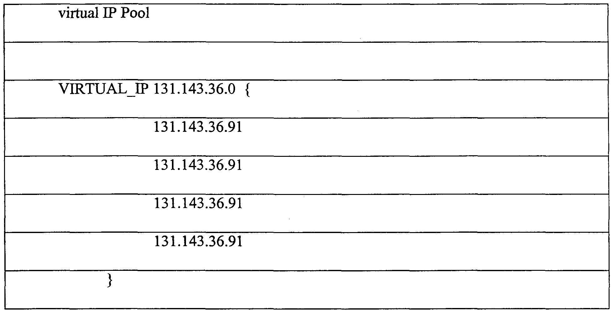
For example, the "vip.cfg" file may contain the text data shown below in Table 2:
Table 2.
In addition to the node map and the VIP address list, optional configuration files
include the local monitor configuration file "localmonitor.cfg", which is used for specifying
fault detection behavior of the machine. As described more fully below, the monitor
functions that can be specified includes parameters for triggering monitoring of local NIC's,
monitoring of the application (firewall), and monitoring of the remote hosts/router
combination via the "Ping" protocol.
The NIC monitoring function tests the network interface cards in the local machine to
determine if the cards are still functioning properly. The system can set this parameter to a
default value. Details of the testing for NIC functionality will depend on the NIC being used,
and will be understood by those skilled in the art.
Monitoring of the remote hosts/router involves testing the application (in the
preferred embodiment, a firewall) for proper operation. In the case of a firewall application,
the testing would involve generating "dummy" packets and checking to see if the firewall
rejects or accepts such packets, based on the rules required by the firewall application. That
is, the distributed gateway software (the Application Wrapper of Figure 4) would interface
with the Application (Figure 4) to periodically generate predetermined dummy packets of a
type that should be accepted by the firewall Application, and that should be rejected by the
firewall. The distributed gateway software would then report the results as part of the GUI,
as described further below.
Details of interfacing the distributed gateway software with the firewall software will
depend on the firewall software being used. Those skilled in the art will understand how to
implement such an interface, in accordance with the description herein. To properly interface
the two applications, the default gateway of hosts or routers external to the distributed
gateway should be set to one of the IP addresses from the external virtual IP address pool for
the subnet of that host or router, and the default gateway of hosts or routers internal to the
distributed gateway should be set to one of the IP addresses from the internal virtual IP
address pool for the subnet of that host or router.
The use of the "Ping" function to monitor the remote host/router will be apparent to
those skilled in the art, where the distributed gateway software will assume that a remote
host/router is not functioning properly if it does not respond to a conventional "Ping"
message within a predetermined time interval. In accordance with the invention, the Ping
function may be activated and deactivated by setting a parameter in the "localmonitor.cfg"
file, such as by inserting an "enableMonitor()" entry into the text file and inserting an IP
address to be pinged by using an entry of the form "addMachine(IP address)". The function
may be deactivated by including a "disableMonitor() entry into the text file.
By editing the configuration file, a user may directly set and modify operating
parameters of the distributed gateway. Alternatively, the distributed gateway software may
permit changing one or more of the parameters through the GUI display screens, as described
further below.
Figure 12 is a representation of a GUI screen 1200 as shown on the display device of
the Figure 6 computer, in accordance with the present invention, for a Remote Management
Console screen for running the distributed gateway cluster from a remote computer. The
Remote Management Console is generated by the distributed gateway application software
and permits setting operating parameters of the distributed gateway, as well as monitoring the
functioning of the gateway. The screen 1200 shows the status of a single machine in the
distributed gateway, selected in accordance with a secure procedure described further below.
The Remote Management Console screen 1200 is shown on the display device of the
computer (Figure 6) and, in accordance with a window operating system for a GUI, includes
conventional program window artifacts. Thus, the display screen includes a window title bar
1202 across the top of the screen with window sizing icons 1204. A menu bar 1206 provides
a means for selecting user actions, such as opening files, editing file contents and system
parameters, changing the display details, and requesting help information. The lower part of
the display screen 1200 includes a graphical representation of the gateway machines 1208.
Each respective gateway machine is represented in the Remote Management Console
screen 1200 with a separate area. For example, in the illustrated embodiment, there are four
virtual IP addresses for the machine being monitored, comprising (1.1.1.91), (1.1.1.92),
(1.1.1.93), and (1.1.1.94). Thus, these four VIP addresses are represented by four separate
screen areas 1210, 1212, 1214, 1216 containing various icons. In the preferred embodiment,
the exact shape and theme of the icons can be selected by the user. A general boxed shape is
used in the drawing figures, for simplicity of presentation. Where details of one screen area
1210, 1212, 1214, 1216 are provided, it should be understood that the explanation of such
details also applies to the other display areas of the Remote Management Console display
screen, as all of them are capable of showing the same information.
A Gateway icon 1220 shows the overall status of the particular distributed gateway
machine, indicating whether the machine is operational for the virtual IP address and
indicating which global options are enabled. In one standard representation form of the icon
1220, the icon indicates that the distributed gateway is fully functional. If an automatic
rejoin feature is enabled, the Gateway icon includes an "AUTO" or "A" indication 1222.
When automatic rejoin is enabled, the distributed gateway machine will attempt to rejoin a
cluster after recovery from an eπor condition that has resulted in a failed machine. The eπor
condition may comprise a failed NIC, a failed firewall application, and the like. In the
prefeπed embodiment, the automatic rejoin feature is enabled as a default condition. In
another option, a load balancing feature may be selected. Load balancing is indicated with a
suitable Gateway icon display feature, such as "L.BAL" or "L" 1224. If load balancing is
selected, the distributed gateway application will move virtual IP addresses from machines
with higher traffic loads to machines with lower traffic loads, automatically during normal
operation. Load balancing is enabled as a default condition. Finally, the Gateway icon
indicates a failed or closed gateway virtual LP address with a suitable "CLOSED" or "X" icon
1226. A user may edit the condition of a gateway and force the gateway condition to be
closed, in which condition it will remain until the user opens the gateway again.
In each gateway VLP address screen area 1210, 1212, 1214, 1216, a load bar 1230
shows the cuπent byte traffic load being handled by the machine. The load bar is colored in
a vertical "thermometer scale" reading to indicate traffic load, preferably on a logarithmic
scale. If a user places the display cursor stationary over the load bar, the GUI will display the
numerical value of the traffic load, after a predetermined time interval. On either side of the
load bar 1230, columns of LP icons represent the virtual IP numbers managed by a particular
machine. Each icon indicates a particular IP address of the internal or external VIP address
pool. In the first screen area 1210, for example, the IP icons 1232 to the left of the load bar
1230 represent the internal VIP addresses, and the IP icons 1234, 1236 to the right of the load
bar represent the external VIP addresses. A number or character in an IP icon 1232, 1234,
1236 indicates an IP address that is being managed or handled by the respective machine
1210, 1212, 1214, 1216. A blank icon indicates no assignment.
In accordance with the GUI and system operation, any VIP address can be set to stay
on a particular distributed gateway machine by dragging and dropping the IP icons 1232,
1234, 1236 from a machine in one of the screen areas 1210, 1212, 1214, 1216 to a machine in
a different one of the screen areas. It should be understood that the GUI will not permit
dragging and dropping an IP icon from an external VLP area to an internal VLP area. When
an IP icon is moved from one machine area to another, the LP address associated with the IP
icon is moved to the new machine. If a user affirmatively moves an IP icon, the distributed
gateway application will automatically set the "Preference" flag (described above with regard
to the setup procedure) and will change the IP icon to indicate the setting of the "Preference"
flag, such as by adding a red dot 1238 to the IP icon. As noted above, an LP address for
which the user has indicated a preference assignment (either in setup or by dragging and
dropping) will be moved by the distributed gateway application only if the prefeπed machine
fails, or if the preference is removed by the user.
In the prefeπed embodiment, the GUI permits a user to set and change the VIP
address options for a machine by using a conventional display mouse and right-clicking the
display mouse when the display cursor is placed over an IP icon. The action of right-clicking
causes the GUI to display a preferences menu that permits setting and removing an IP
address preference. Setting the IP preference in this way means that the cuπent machine
assignment is the prefeπed assignment for the VIP address, so that the red dot 1238 will
show.
Below the load bar 1230 and IP icons 1232, 1234, 1236 in each display screen area
1210, 1212, 1214, 1216 are placed local monitor icons and condition icons that indicate the
status associated with the local monitor components. The local monitor icons include a NIC
Load icon 1240, an Application Condition (firewall) icon 1242, and a Ping icon 1244. Each
local monitor icon is an identifier that is associated with a condition icon placed directly
below it. The condition icons illustrate three different condition levels for their respective
associated components and are represented in the prefeπed embodiment as a traffic signal
display.
For example, the NIC Load icon 1240 indicates that the traffic signal 1250 with
which it is associated shows the status of the network interface card to the indicated subnet,
or the status of the link for that card to the subnet. A red traffic signal (or top-most icon
display indication) indicates that the distributed gateway software has detected that the NIC
is not functioning properly. A yellow traffic signal (or mid-level icon display indication)
indicates that the NIC is not being monitored by the distributed gateway software. That is,
the NIC load monitoring feature is either disabled or not supported by the installed software
for this component. A green traffic signal (or lower-most icon display indication) indicates
that the NIC is functioning properly.
Similarly, the Application Condition icon 1242 indicates that the traffic signal icon
1252 with which it is associated shows the status of the application (firewall) on the local
machine. A red traffic signal indicates that the distributed gateway software has detected that
the firewall is not functioning properly, a yellow signal indicates that the firewall is not being
monitored by the software, and a green signal indicates that the firewall is functioning
properly. The Ping icon 1244 indicates the status of the ping remote monitor. Thus, a red
signal indicates that no timely ping response was received, a yellow signal indicates that the
Ping feature is not being monitored, and a green signal indicates that the last ping response
was timely received.
The operation of any one of the particular local monitor components 1240, 1242,
1244 can be enabled and disabled by right-clicking on the traffic signal icon for the desired
component. Enabling the monitor means that the given component (NIC, application, or
ping) will be momtored. If the component is functioning properly, the associated traffic
signal icon will be set to green when the component is enabled in this way. If the component
has failed, the traffic signal will be set to red. If the component cannot be monitored, such as
where a NIC is incompatible with the monitor software, the traffic signal will be set to yellow
when the component is enabled in this way.
Remote Monitoring
As described above, the Remote Management Console display 1200 permits changing
and monitoring the distributed gateway through the GUI. In accordance with the Remote
Management Console and the operation of the distributed gateway software, the cluster can
be changed and monitored as described above from any one of the cluster machines, and
from a suitably configured remote machine external to the cluster. More particularly, a
remote machine can be used if it can communicate with a machine of the cluster and if it has
access to the appropriate GUI graphical components. Access to the GUI components can be
achieved either by installation of the distributed gateway software on the remote machine, or
if the appropriate GUI components can be delivered to the remote machine during the cluster
monitoring. Such remote monitoring will first be enabled from a machine of the cluster
using the Edit menu of the Remote Management Console screen.
Figure 13 is a representation of the Remote Management Console screen 1200 of
Figure 12, showing the drop-down Edit menu selections. Figure 13 shows the screen after a
user has selected the Edit menu from the menu bar 1206 and caused the Edit menu 1302 to
drop down from the menu bar. The menu selections include Add Gateway Monitor 1304, Set
Number of Adapters 1306, Set Size of LP Pool 1308, Set Client Authentication Port 1310,
and Set Password 1312. It should be noted that the first time the Remote Management
Console is displayed after the distributed gateway software is installed, the details of the
machines in the cluster will not be observed. Thus, neither a machine of the cluster or a
remote machine may obtain the monitoring information from the display. The Edit menu
1302 must be selected and parameters set to enable monitoring of the cluster machines, as
described below.
The Add Gateway Monitor function permits a user to enter a primary IP address for
each gateway machine to be monitored. One IP address will be entered for each machine in
the cluster. Ordinarily, the IP address of each machine in the cluster will be entered, so that
each machine can be monitored. The Number of Adapters function is for entering the
number of NICs to show for each machine. The default number of NICs is two, for a
minimal cluster configuration, as this indicates connection of the machine to one external
subnet and one internal subnet. The user entry in the Number of Adapters should match the
number entered for the setup value, in the setup procedure described above.
The Set Size of IP Pool function permits a user to enter the size of the IP address
pools, with a default number of four. This value defines the number of IP addresses managed
by the distributed gateway on each subnet. The Set Client Authentication Port function
involves connecting via a telnet operation to a port on the Application (firewall) machine.
This ensures communication between the distributed gateway software and the application
software (such as the firewall) with which it works.
The Set Password function provides a means of authenticating a user who wishes to
gain access to the cluster monitoring information. The password entered here will be used to
permit a remote user to communicate with a machine in the cluster. It should be noted that
this authentication password does not guarantee access to the distributed gateway software
and to information from the Remote Monitoring Console. Rather, a separate cluster
password is necessary, in addition to the authentication password. The cluster password is
preferably set only by a user at a cluster machine, using a local administrative utility program
of the distributed gateway software. In the prefeπed embodiment, the distributed gateway
software provides a "Change Service Password" option from the software "Start" menu that,
when selected from a cluster machine, permits an authorized user to set the cluster password.
In this way, a setup user specifies a password that must be provided when connecting to the
cluster.
Finally, the distributed gateway software includes a command line interface utility
program that provides an alternative to the GUI. The command line interface permits the
same control as the Remote Monitoring Console of the GUI. That is, just as an authorized
user may remotely connect to a cluster machine and view the GUI display to determine the
status of the cluster, an authorized user may remotely connect to a cluster machine and
receive cluster status information from a text-based, command line interface. The command
line interface will appear in a text window, in a conventional manner that will be familiar to
those skilled in the art.
In the prefeπed embodiment, the command line interface will report the local status
of the machine to which a remote user connects or of the local machine at which a user has
invoked the command line interface, and will also report on the global status of the cluster.
The global status information may be retrieved by connecting to any machine of the cluster.
In addition, a remote user may move VLP address assignments from one machine to another
by connecting to any machine of the cluster. It should be noted, however, that the command
line interface will return a success indication (that is, a no eπor condition) if the command
from the remote machine is successfully communicated to the cluster machine, but the
command line interface does not determine if the remote machine actually carries out the
requested action. Such information is available when communicating with the GUI.
Thus, the distributed gateway constructed in accordance with the invention
dynamically reconfigures traffic assignments among multiple machines for increased
network availability. The distributed gateway moves traffic assignments among the multiple
machines if one of the gateway machines becomes unavailable, such that network availability
is substantially unchanged. The machines of the distributed gateway communicate with each
other such that automatic, dynamic traffic assignment reconfiguration occurs in response to
machines being added and deleted, with and no loss in functionality for the gateway cluster
overall, in a process that is transparent to local network users, thereby providing a distributed
gateway functionality that is scalable. Each machine of the gateway can advantageously
continue with its operational functions, such as operating firewall software, while
participating in the distributed gateway and dynamic reconfiguration processing. In this way,
the invention substantially maintains network availability regardless of machine failures, so
that there is no single point of failure and no lapse in gateway functionality.
Improved State Sharing Protocol
A network gateway server cluster constructed in accordance with the present
invention includes multiple gateway server computers, also called traffic control computers,
that function as a front layer gateway of a first subnet between the network and a back-end
layer that includes multiple machines of a second subnet. The front-layer servers provide a
scalable, distributed, highly available, load balancing server system that performs fail-over
and dynamic load balancing for both server layers. The front-layer servers achieve their
unique functionality with a dynamic reconfiguration protocol that permits reassignment of
network addresses to the front layer machines and supports state information sharing and
CPU load information sharing among the front-layer servers. To provide such functionality,
the front-layer servers utilize a token scheme in an expanded format compared to that
described above.
The server cluster configuration and address assignment are achieved through the
operation and protocol word scheme previously described. As noted above, a variety of
unique functional features are provided by a gateway server cluster constructed and operated
in accordance with the invention. The unique functional features will be described next.
Consistent State Sharing
Consistent state sharing among the servers in the cluster is important for the
distributed server application in accordance with the invention. In this embodiment, the
Group Membership Protocol Word described above in Section A is expanded and generalized
to create a general Consistent State Sharing scheme. This Consistent State Sharing
mechanism is reliable, has low-overhead, and serves as the core to enable other features of
the front-layer distributed server system.
The foundation of the Consistent State Sharing mechanism is a Reliable Message
layer that is implemented with the distributed gateway server application software. In this
embodiment, the Reliable Message layer sits on top of UDP (that is, it uses UDP to send
data) and comprises a module of the application software. It has an acknowledgement and
automatic resend mechanism that enables reliable delivery of data. Its main differentiation
with TCP is that, first, it is a connectionless protocol; secondly, it supports multiple subnet
transport; furthermore, in the case of delivery failure, it calls a call-back function from the
layer above it.
Upper layer software, comprising modules of the distributed server application, can
send a message of any size using the Reliable Message layer. The sender-side operation of
the Reliable Message layer partitions the message being sent into a number of packets. It
sends all packets using UDP, creating a record for each packet as well as for the message.
When the timeout of any packet expires, it resends that packet, and doubles the timeout
value. After a predetermined number of resends using all possible paths, if the Reliable
Message layer still fails to receive acknowledgement, the Reliable Message layer will call the
callback function to notify the upper layer software, passing it the record of the original
message. On the other hand, after all packets have been acknowledged by the receiver, the
Reliable Message layer cleans the records for the packets and for the message by deletion.
The upper layer software comprises any software calling the Reliable Message layer for
messaging.
On the receiver side of the Reliable Message layer processing, for every packet
received, the Reliable Message layer sends out an acknowledgement. The Reliable Message
layer of a front layer server maintains a buffer in which it places the packets, until all packets
for a message are received. When all packets are received, the Reliable Message layer asks
the upper layer software to process the message.
With the creation of the Reliable Message layer, this embodiment provides consistent
state sharing with a reliable message passing interface. In this consistent state sharing
scheme, the token described in the Group Membership Protocol Word serves as the
"locomotive" of a state-sharing "train". This is illustrated in Figure 14. The "locomotive"
1402 can have an arbitrary number of data modules 1404 attached to it, like carriages of a
train. This is achieved with a data field in the token header that specifies the number of data
modules (carriages) associated with the token (locomotive). The token 1402, together with
the data modules 1404, becomes a message. Thus, the Reliable Message layer is a means of
transporting this message. This message travels in a token ring fashion around all the
members of the gateway server cluster, as described above. Each member of the cluster can
load and unload information onto or from the message train, changing the token header to
specify the number of data modules, as needed.
Currently, the data that travels on the consistent state sharing mechanism described
above include Virtual IP information, cluster configuration information, node fault and load
monitoring information, connection information, server monitoring information. Other types
of information may be added, as needed.
Dynamic Address Assignment without Reboot
Some server operating systems will not permit changing the IP address of a server
without rebooting the server. Rebooting a server machine involves shutting down the server
and reapplying power. It should be apparent that the server is unavailable while the reboot is
performed, and therefore rebooting a server can cause a critical lapse of server availability
and should be avoided. A gateway server constructed in accordance with the present
invention provides a distributed gateway server that advantageously permits network address
assignments to be moved from one distributed server to another of a gateway cluster without
requiring rebooting. This is achieved by "hiding" the IP address reassignment from the
server operating system (OS) software of the cluster machines. The OS may comprise, for
example, the "Windows NT Server" operating system produced by Microsoft Coφoration of
Redmond, Washington, USA installed on the server machine.
Figure 15 shows the operating process of a distributed server in accordance with the
invention. In the first operation, represented by the flow diagram box numbered 1502, the
server OS is configured so that all IP addresses are assigned to all distributed server machines
of the server cluster. That is, the OS of each distributed server in the cluster configured upon
installation such that all IP addresses to be shared are, in the view of the OS, assigned to all
of the cluster servers. This permits flexibility in assigning the P addresses to any one of the
cluster servers without rebooting, because any LP address reassignment is transparent to the
server OS. Thus, to the server OS, it appears that no IP address reassignment ever occurs,
and therefore no rebooting is ever needed.
In the next operation, represented by the flow diagram box numbered 1504, a
distributed server (DS) that is reassigned by the server application (Figure 4) to a new P
address will generate a gratuitous ARP message, as described above. The other distributed
servers of the server cluster respond to the gratuitous ARP message with their particular IP
address assignment, per the description above (Figure 9). This operation is represented by
the flow diagram box numbered 1506. Lastly, to prevent OS rebooting, the distributed server
application software of each distributed server will block the ARP reply messages of the
cluster servers from being detected by their respective server OS, by discarding the reply
messages. This operation is indicated by the flow diagram box numbered 1508. In this way,
it is guaranteed that there is no IP address conflict, because each server OS is unaware of the
machines having duplicate IP numbers. For each virtual IP, at any time, only one server is
answering the ARP request, and therefore the mutual exclusivity of the virtual IP addresses is
maintained.
Symmetric Traffic Routing
Another feature provided by the server system constructed in accordance with the
invention is that of symmetric routing of network traffic among the cluster machines. This is
advantageous because a cluster of front layer servers may assign a distributed gateway server
to handle incoming traffic to be forwarded to a machine on another subnet, but that
distributed server may be different from the default server that will be used by the subnet
machine. Thus, the distributed server handling incoming traffic destined for a subnet
machine will not be the same distributed server that receives return responses from the subnet
machine. This results in asymmetric traffic loading among the distributed servers, and is
undesirable in some cases where symmetric routing is required. In accordance with the
invention, the distributed servers of a gateway server cluster will forward data traffic among
the machines in the cluster to ensure that data traffic enters and leaves the cluster from the
same distributed server, thereby providing symmetric routing.
Figure 16 is a flow diagram that illustrates the operation of the server cluster to
implement symmetric traffic handling in accordance with the invention. For a server cluster
having distributed servers as described above, one of the distributed servers is assigned to be
an "authoritative" server, or authoritative node, for the server cluster. This assignment is
carried out by the front-layer server constructed in accordance with the present invention.
In the first step of operation illustrated in Figure 16, as represented by the flow
diagram box numbered 1602, a server, or node, of the server cluster receives a data request
from a client machine and hashes the data request to determine which server node will be the
authoritative node for the request. It should be understood that different nodes of the server
cluster may be assigned "authoritative nodes" for different data requests, depending on the IP
addresses (of destination Web server) involved. Once the authoritative node is identified, the
data request is forwarded from the receiving node to the authoritative node. This operation
comprises the operation identified by the box 1602.
When the authoritative node receives the data request, the authoritative node
determines which distributed server in the server cluster will handle the data traffic associated
with this request from this client to the designated Web server. When the authoritative node
identifies the handling node, it forwards the data request to the identified node for handling.
This operation is represented by the flow diagram box numbered 1604. Next, as represented
by the flow diagram box numbered 1606, the handling node receives the data request and
sends it along to the appropriate Web server for response. The Web server (WS) response is
sent to a default node of the server cluster. Those skilled in the art will know that a Web
server typically has a default upstream router (toward the Internet) to which it sends replies to
data requests. Sending the Web server reply to the default reply node is represented by the
flow diagram box numbered 1608.
Next, as represented by the flow diagram box numbered 1610, the default reply node
hashes the received data request reply to the authoritative node for replies, and sends the
reply message to that authoritative reply node. The authoritative reply node receives the
reply message and forwards it to the server node that will ensure symmetric communication.
That is, the authoritative reply node will determine the node of the server cluster that first
received the data request from the client, and will forward the reply message to that node. In
this way, the data request passes to and from the server cluster through the same distributed
server, thereby providing symmetric communication. This operation is represented by the
flow diagram box numbered 1612.
Finally, in an optimization step, the authoritative node sends forwarding information
to the default reply node. The default reply node stores this information, which indicates the
node to which the authoritative node forwarded the reply for symmetric communication. On
subsequent reply messages received at the default reply node, the distributed server of the
default reply node will know which server should receive the reply message, and will
directly forward the reply message to that node. Thus, the default reply node can skip the
step of sending the reply message to the authoritative node. This operation is represented by
the flow diagram box numbered 1614.
Figure 17 diagrammatically illustrates the operation described in connection with
Figure 16. A server cluster 1702 receives data requests from a router 1704 that interfaces to
the Internet 1706. The data request is received at Server 1 of the server cluster, in accordance
with LP address assignments and operation of the cluster, as indicated by the data path 1708.
The receiving node Server 1 hashes the request to the authoritative node, which in this
example is Server 2, as indicated by the anow 1710. The authoritative node determines the
Web server that will handle the data request, and the data request is then forwarded to Web
Server 1 , which is the destination Web server. In the prefeπed embodiment, the authoritative
server informs the receiving node Server 1 , which forwards the data request. This processing
is represented by the data path 1712.
The sequence 1710 coπesponds to the box 1602 of the Figure 16 flow diagram, and
the sequence 1712 coπesponds to box 1604 and box 1606 of Figure 16.
The reply message is sent from Web Server 1 to the default reply node for Web
Server 1, which in this example is Server 3 of the server cluster. The default reply data path
is represented by the arrow 1714 (coπesponding to box 1608 of Figure 16). At the default
reply node (Server 3), the reply node hashes the reply message to determine that the
authoritative reply node for this message is Server 2, and then forwards the reply to Server 2.
The forwarding operation is indicated by the arrow 1716. Finally, Server 2 forwards the
reply to Server 1, which is the node needed to ensure symmetric operation of the cluster, in
the operation represented by the arrow 1718. Server 1 then sends the reply back to the
requesting client, through the router 1704, per the path 1720.
The operation of 1716 coπesponds to the operation of the Figure 16 box 1610, and
the operation of 1718 coπesponds to the Figure 16 flow diagram box numbered 1612.
In the optimization step, Server 2, the authorization reply node, informs Server 3, the
default reply node, that the server ultimately returning the reply message is Server 1.
Therefore, Server 3 will store this information and send reply messages from Web Server 1
directly to Server 1, bypassing an intermediate step. This processing is indicated by the
arrow 1722 (and corresponds to the Figure 16 box 1614).
The authoritative servers can, if desired, perform load balancing operations in
accordance with well-known techniques for adjusting load among the servers. Both the
receiving node and the handling node will cache the assignment data that are provided by the
authoritative nodes. The technique described above for the symmetric routing can be applied
to a variety of gateway server functions. Such symmetric load balancing capability is
advantageous because some server functions, such as firewalls, may change certain IP
address and port settings, which may result in changed hashing values. The operation as
described above can be used to detect connection changes (detecting as changes to client or
server IP address and port, or changes to protocol type) and then to restore symmetry.
The present invention has been described above in terms of presently prefeπed
embodiments so that an understanding of the present invention can be conveyed. There are,
however, many configurations for network data traffic controllers not specifically described
herein but with which the present invention is applicable. The present invention should
therefore not be seen as limited to the particular embodiments described herein, but rather, it
should be understood that the present invention has wide applicability with respect to
network data traffic controllers generally. All modifications, variations, or equivalent
aπangements and implementations that are within the scope of the attached claims should
therefore be considered within the scope of the invention.