WO1999061985A1 - Distributed computing environment using real-time scheduling logic and time deterministic architecture - Google Patents
Distributed computing environment using real-time scheduling logic and time deterministic architecture Download PDFInfo
- Publication number
- WO1999061985A1 WO1999061985A1 PCT/US1999/006634 US9906634W WO9961985A1 WO 1999061985 A1 WO1999061985 A1 WO 1999061985A1 US 9906634 W US9906634 W US 9906634W WO 9961985 A1 WO9961985 A1 WO 9961985A1
- Authority
- WO
- WIPO (PCT)
- Prior art keywords
- communication
- time
- computer
- node
- future
- Prior art date
Links
- 238000004891 communication Methods 0.000 claims abstract description 300
- 230000000977 initiatory effect Effects 0.000 claims abstract description 13
- 238000000034 method Methods 0.000 claims description 76
- 230000003993 interaction Effects 0.000 claims description 26
- 238000012545 processing Methods 0.000 claims description 18
- 230000001351 cycling effect Effects 0.000 claims description 6
- 230000004044 response Effects 0.000 claims description 2
- 230000010354 integration Effects 0.000 claims 1
- 238000013459 approach Methods 0.000 abstract description 11
- 230000008569 process Effects 0.000 description 45
- 238000004886 process control Methods 0.000 description 22
- 238000010586 diagram Methods 0.000 description 18
- 241000193690 San Angelo virus Species 0.000 description 15
- 238000005516 engineering process Methods 0.000 description 14
- 238000004590 computer program Methods 0.000 description 13
- 230000006870 function Effects 0.000 description 9
- 230000005540 biological transmission Effects 0.000 description 8
- 239000002131 composite material Substances 0.000 description 6
- 238000009826 distribution Methods 0.000 description 6
- 238000004519 manufacturing process Methods 0.000 description 6
- 230000008901 benefit Effects 0.000 description 5
- 230000000903 blocking effect Effects 0.000 description 5
- 230000001419 dependent effect Effects 0.000 description 4
- 230000007246 mechanism Effects 0.000 description 4
- 238000013461 design Methods 0.000 description 3
- 230000000694 effects Effects 0.000 description 3
- 239000000203 mixture Substances 0.000 description 3
- 230000006855 networking Effects 0.000 description 3
- 230000009286 beneficial effect Effects 0.000 description 2
- 238000012512 characterization method Methods 0.000 description 2
- 230000008570 general process Effects 0.000 description 2
- 238000010348 incorporation Methods 0.000 description 2
- 238000007726 management method Methods 0.000 description 2
- 238000005259 measurement Methods 0.000 description 2
- 238000012986 modification Methods 0.000 description 2
- 230000004048 modification Effects 0.000 description 2
- 238000011084 recovery Methods 0.000 description 2
- 230000003252 repetitive effect Effects 0.000 description 2
- 239000007787 solid Substances 0.000 description 2
- 239000000126 substance Substances 0.000 description 2
- 230000036962 time dependent Effects 0.000 description 2
- 238000012546 transfer Methods 0.000 description 2
- 241000196324 Embryophyta Species 0.000 description 1
- 241000282412 Homo Species 0.000 description 1
- 101100172132 Mus musculus Eif3a gene Proteins 0.000 description 1
- 230000004308 accommodation Effects 0.000 description 1
- 230000009471 action Effects 0.000 description 1
- 230000002730 additional effect Effects 0.000 description 1
- 238000004458 analytical method Methods 0.000 description 1
- 239000000969 carrier Substances 0.000 description 1
- 230000008859 change Effects 0.000 description 1
- 239000013078 crystal Substances 0.000 description 1
- 238000001514 detection method Methods 0.000 description 1
- 238000011161 development Methods 0.000 description 1
- 230000005611 electricity Effects 0.000 description 1
- 230000006872 improvement Effects 0.000 description 1
- 230000002452 interceptive effect Effects 0.000 description 1
- 230000003287 optical effect Effects 0.000 description 1
- 230000010355 oscillation Effects 0.000 description 1
- 230000036961 partial effect Effects 0.000 description 1
- 230000037361 pathway Effects 0.000 description 1
- 230000000737 periodic effect Effects 0.000 description 1
- 238000007639 printing Methods 0.000 description 1
- 238000012913 prioritisation Methods 0.000 description 1
- 230000000644 propagated effect Effects 0.000 description 1
- 230000000717 retained effect Effects 0.000 description 1
- 238000003860 storage Methods 0.000 description 1
- 230000001360 synchronised effect Effects 0.000 description 1
Classifications
-
- G—PHYSICS
- G06—COMPUTING; CALCULATING OR COUNTING
- G06F—ELECTRIC DIGITAL DATA PROCESSING
- G06F9/00—Arrangements for program control, e.g. control units
- G06F9/06—Arrangements for program control, e.g. control units using stored programs, i.e. using an internal store of processing equipment to receive or retain programs
- G06F9/46—Multiprogramming arrangements
- G06F9/48—Program initiating; Program switching, e.g. by interrupt
- G06F9/4806—Task transfer initiation or dispatching
- G06F9/4843—Task transfer initiation or dispatching by program, e.g. task dispatcher, supervisor, operating system
Definitions
- This invention is directed to the field of data processing control systems, particularly to integrated systems where a plurality of computers execute their logic in a coordinated manner within a network.
- the primary application of the system described in this specification is for computerized control of machines deployed on a large physical scale (for example a chemical manufacturing facility), although benefits to endeavors related to plural computer processors, parallel computer processors, and networked computer processors are also enabled.
- This invention describes a system and method for enabling a plurality of geographically dispersed computers to be networked for enabling time coordinated inter-activity. This resultant network enables task coordination and facilitates the implementation of other qualities beneficial to the task being performed by the system - qualities such as redundancy, security, and high throughput.
- Vector processors as discussed in sections 7.1 and 7.2 (“Vector Processors") of Computer Architecture A Quantitative Approach by John L. Hennessy and David A. Patterson (Morgan Kaufmann; San Mateo, California; 1990; pages 351 -363) are one manifestation of such systems, and processor-memory pair approaches such as the Cm * design discussed from pages 11 to 18 of "Parallel Processing - The Cm * Experience" by E. F. Gehringer, D. P. Siewiorek, and Z. Segall (Digital Press via Editorial Inc.; Rockport, Massachusetts; 1987) provide a second example of these types of approaches.
- Process control systems development is characterized by an ever-increasing incorporation and management of issues at large in the system being controlled, requiring that a comparably larger amount of logic on a comparably larger amount of data be executed in a time frame which is not permitted to expand. This can be achieved to some degree by hardware which processes logic more quickly and holds more data in an addressed physical store, but there are substantial costs in pursuing this solution. What is needed to resolve the ability of future systems to effectively expand their comprehensive treatment of the control situation is to truly provide a solution path for enabling a very large number of distributed computers to execute massive amounts of logic in a mutual manner which is time-synchronous across an entire network.
- the present invention provides such a method and system.
- the invention provides a computer implemented method for enabling a plurality of computer nodes in mutual data communication to execute logic in a coordinated manner by
- the described embodiment provides a computer network architecture, having a message carrier with a plurality of computers coupled to it; a clock system (accessible by all computers in the network) for maintaining time synchronism among the computers; and a scheduler for determining the sequence of communication between the computers by causing the message carrier to establish communication between selected computers based on time-deterministic tasks being performed by the computers.
- the described embodiment further provides a global time system for aligning the sense of time in the set of computers to a globally defined reference.
- the described embodiment further provides a computer implemented method for enabling a plurality of member nodes to execute logic in a coordinated manner.
- the described embodiment further provides for concurrency in communications between computers via the message carrier.
- the described embodiment further provides provides a computer implemented method for scheduling tasks for resource objects in a plurality of resource objects functioning as a collective group.
- the described embodiment further provides a method by which different computers can align their definition of time by adjusting their oscillator's rate of oscillation.
- the computer network architecture is enabled with a message carrier supporting multiple communication paths; a plurality of computers coupled to the message carrier, with each computer being programmed to perform time-deterministic tasks by cycling through a plurality of different operating states, including a communication state; a clock system accessible by all the computers for maintaining time synchronism among the computers; and a scheduler coupled to the message carrier for determining the sequence of communication between the computers by enabling the message carrier to establish communication between selected computers based on the time-deterministic tasks being performed by the computers.
- a computer node (element for computing with an independent central processing unit) in the plurality of computer nodes can execute logic in coordination with the other nodes by being connected to a message carrier along with the other computer nodes where there is also a provision for (a) master scheduling capability in one computer node to establish a master scheduler; (b) defining, in each computer node, a communication request list of each communication needed by the computer node with any other computer node respective to a future time period; (c) sending of the communication request list from each computer node to the master scheduler via the message carrier; (d) receiving of, in each computer node, a communication schedule from the master scheduler via the message carrier; and (e) defining, in each computer node, a local task schedule from the communication schedule.
- the above approach enables a plurality of member nodes in a system to execute a large amount of logic in a coordinated manner on a group of distributed platforms.
- the step of defining a reference moment time value is performed in one embodiment by the master scheduler.
- the step of defining a communication request list in each member node in one embodiment limits the communications to a maximum number in the future time period and each communication has an duration time attribute and the value of the duration time attribute is less than a fixed maximum value in order to achieve efficient operation.
- Use of a global time system in one embodiment enables a universal understanding of time across a large number of different computer nodes (member nodes) in an extended system.
- the method for scheduling involves a process of scheduling tasks for resource (member) objects in a plurality of resource objects functioning as a collective group; and this computer implemented process (called an "apparent critical resource” process) involves the steps of:
- the message carrier has a plurality of channels for permitting concurrency in the communication events, the step of scheduling being respective to the plurality of channels as a group wherein the earliest available time is respective to any channel in the message carrier.
- each member node has a variable speed oscillator for adjusting a local clock to align with a global clock on the network.
- Time alignment logic and oscillator rate adjustment logic for execution by the computer circuitry are also provided to achieve rapid time alignment of the particular member node (computer node).
- the message carrier used in the described embodiment is enabled with a network topology which can be manifested (in the preferred embodiment) with a crossbar switch, or, in an alternative embodiment, with a radio frequency communications system.
- Figure 1 presents a diagram of the data flows between the various elements in a distributed network.
- Figure 2 depicts a distributed network of computing elements which are resident in physically different locations throughout the world. This figure includes a network of computing elements, a master scheduler, and a common source of time.
- Figure 3 presents a diagram of a network in a bus structure.
- Figure 4 shows a distributed computing environment where the network is implemented in a ring topology.
- Figure 5 presents a diagram of a network in a switched star topology which is a preferred network architecture embodiment.
- Figure 6 presents a diagram of data structures communicated between the computing elements and a master scheduler.
- Figure 7 depicts a flowchart of the process implemented in the master scheduler in the scheduling of communications between two separate computing elements.
- FIG 8 presents a simplified diagram of the scheduling logic (software in execution by electrical circuitry) implemented in the master scheduler in the scheduling of communications between two separate computing elements.
- Figure 9 presents a detailed flowchart of the scheduling logic which is followed at the master scheduler.
- Figures 10 presents a bar chart depicting the first scheduled communications between two separate computing elements after the first connection is scheduled.
- Figure 11 presents a bar chart depicting the scheduled communications between computing elements after all connections are scheduled which can be scheduled in the first step.
- Figure 12 presents a bar chart depicting the scheduled communications between computing elements after all connections have been scheduled.
- Figure 13 provides a detailed composition of the Message Carrier, the Master Scheduler, the Clock, and the Member Nodes.
- Figure 14 shows the relationships between the technologies which have been combined in the preferred embodiment, with emphasis on those most critical to the application.
- Figure 15 presents a flowchart of the logic which executes in each of the computing elements in order to facilitate communication between the member nodes.
- Figure 16 depicts a diagram of the data flows between the various elements in a distributed network where communications are facilitated by radio frequency.
- the system and method of the present invention implement centralized scheduling of cooperatively performed tasks, time deterministic event operations, and effective real-time synchronization and alignment of oscillators respective to the plurality of computers (also referenced as "member nodes") on the network.
- the time deterministic network involves communicating between separate computing elements based on time rather than on some event (examples of events are the reception of a token or the detected availability of a particular bus).
- Centralized scheduling of cooperatively performed tasks, time deterministic event operations, and effective real-time synchronization and alignment of oscillators respective to the plurality of computers on the network requires that the computers share an essentially common view of the datalogical representation of an actual moment in real-time.
- the computers in a distributed computing network share an essentially common view of the datalogical representation of an actual moment in real-time, they can then be programmed to perform specific tasks based on time. Tasks which involve multiple computers can then be scheduled centrally and a basis is established for time-dependent activities to be invoked on geographically dispersed computers in a deterministic manner.
- determinism in real-time operations characterizes the occurrence of a predefined event at a predefined moment of real-time.
- active redundancy there are two or more computers which are each executing essentially identical logic, exchanging the results from these executions, optionally arbitrating the independently derived results to come to a commonly understood mutual conclusion for further use, and acting to concurrently effect the result. This process proceeds most effectively when data received by each computer is shared with the other computer(s) executing the same logic prior to arbitrating the results, so there must be some mechanism by which the time to begin the arbitration process is mutually determined.
- the mechanism for providing time synchronization between the redundant computers and to schedule the tasks related to a communication instance is (1 ) to provide an essentially identical datalogical representation of the moment in real-time time among the computers; (2) to use a scheduling approach to define in each computer the moment in time when the communication instance in that computer will occur; and (3) to then to implement the appropriate sending, receiving, and linkage tasks in each system involved in the communication instance at the time defined for the communication instance.
- the time at which the referenced arbitration task will be performed is pre-determined after the communications tasks have been scheduled (as opposed to the approach of waiting to determine the start time of the arbitration task after the communication tasks have actually executed).
- the scheduling approach is implemented by execution of scheduling logic.
- logic relates to software (a computer program) whose purpose is achieved in execution by an enabling system of electrical circuitry (usually denoted by the term "computer").
- the scheduling logic used for the scheduling of communications is based on analysis of demands for the resources (for example specific computers, data space within each computer, execution time in each computer, and specific circuits within each computer) which are being scheduled.
- This scheduling logic is used in the scheduling of network communications, but it has further applicability in the scheduling of any resources which require interaction among one another, and it is especially suited for real-time applications.
- the scheduling logic is further designed to be efficient respective to the resources it is responsible for scheduling and to be predictable as to the amount of time required to generate its output, a schedule, from the inputs (that is a collection of connection requests between any two computers on this network).
- the scheduling logic schedules the available resources with the highest demand for the time that the schedule is being created.
- Apparent Critical Resource, or ACR Apparent Critical Resource
- the scheduling logic is not iterative in the sense that, once a particular task is scheduled, it is NOT removed from the schedule in order to pursue an alternative to its placement in the schedule. It is this quality which enables the preferred ACR scheduling logic type of scheduling logic to be well-suited for real-time applications.
- Figure 1 presents a data flow diagram 130 of the general elements and associated data flows between the various general elements in a distributed network and shows a message carrier 100, a first member node 107 and a second member node 108, a master scheduler 106 for coordinating communications between member nodes 107, 108 via data communication path 101 and data communication path 102, clock alternatives (as clock 109 and alternative clock 110) for achieving synchronization between member nodes 107, 108 (via data communication path 104, data communication path 105, data communication path 101 , and data communication path 102), and the primary data tables and exchanges required to interact effectively in this distributed computing environment (via data communication path 118, data communication path 117, data communication path 119, data communication path 120, and data communication path 121 ).
- the clock 109 is distributed to the member nodes through the message carrier from the master scheduler (alternatively, the message carrier 100 could distribute an alternative local clock 110 to the member nodes 107, 108 and to the master scheduler 106). This permits all nodes attached to the message carrier to share a common view of time.
- clock 109 represents a global clock for use around the physical globe (for example in North America, in Europe, and in Asia) where the alternative clock 110 represents a clock which has been designated for the network referenced only by message carrier 100 and where a computer executing aspects of message carrier 100 arbitrarily defines time for its affiliated computers in the distributed network.
- Clock 109 or clock 110 periodically output a common clock signal via either linkage 104 or 105, respectively.
- Each member node 107, 108 is responsible for receiving the common clock signal; effectively "synchronizing" (aligning the definition of time in the node to a close tolerance with the definition of time respective to the common clock signal to create a system time base operating in synchronism with an established clock frequency and anchor point) to that common clock signal; receiving an appropriate local event table 114, 116 from the master scheduler 106; formulating a respective task execution list based on the received local event table 116, 114 and any additional tasks which are not described in the local event table 114,
- Each member node 107, 108 generates a connection request list 113, 115 based on the tasks required of the node 107, 108, and forwards these requests at a prescribed time through the message carrier 100 to the master scheduler 106.
- the master scheduler 106 combines the connection request lists 113, 115 from the member nodes into a composite request list 11 1 , which it uses to generate a communications schedule represented in the master event table 112.
- This master event table 112 is then broken apart into sections applicable to each of the member nodes 107, 108 and sent through the message carrier 100 (also at prescribed times) to the member nodes 107, 108 for storage in local event tables 1 14, 116.
- the local event tables 114, 116 are used in the member nodes 107, 108 to control timing for applicable time dependent tasks, including communications with other member nodes.
- Figure 2 depicts a distributed network 220 of computing elements which are resident in physically different locations throughout the world to show an instance of the situation abstracted in the data flow diagram 130 of Figure 1.
- This figure includes a network of computers 201 -214 and two sources of time in clock 203 and clock 214 representing time sources respective to the data flow diagram clocks 109, 110; in this regard, Figure 2 shows clock 203 as the basis for time definition for all systems in North America and Eurasia while clock 206 defines a basis for time definition for the less globally dispersed domain of computers 206, 207, 208, 209, and 214 in Africa.
- clock 203 then, "maps" to clock 109 in the data flow diagram context of Figure 1 and that clock 214 "maps" to clock 110 in the data flow diagram context of Figure 1.
- Figure 2 thereby depicts two possible configurations for distributed computing environments (facilitating the associated message carriers 100, master schedulers 106, and clocks 104, 105).
- a distributed computing environment can be located in a geographically limited area or dispersed throughout the world.
- the clock 203 is preferably a satellite timing distribution system such as the Global Positioning System.
- Figure 3 presents a diagram of a network in a bus structure 330.
- Figure 3 shows the fundamental components of Figure 1 except that the message carrier 100 is a bus 300 connecting the member nodes 107, 108, to the master scheduler 106.
- Figure 4 shows a distributed computing environment where the network is implemented in a ring topology 430.
- Figure 4 shows the fundamental components of Figure 1 except that the message carrier 100 is a ring enabled by ring segments 402, 403, 405, and 401 to effectively connect the member nodes 107, 108, to the master scheduler 106.
- Figure 5 presents a diagram of a network in a switched star topology 530 which is a preferred network architecture embodiment.
- Figure 5 also shows the fundamental components of Figure 1 except that the message carrier 100 is explicitly a switched network implemented in a star topology which connects the member nodes 107, 108 and the master scheduler 106, and that this master scheduler 106 is embedded into the network switch 501.
- This diagram shows the preferred embodiment as it could be used in a large manufacturing process (a manufacturing process referencing the effecting of goods manufacture in an apparatus whose movable components are modified in real-time using control signals from a computer control system executing logic reading measurements from the apparatus and outputting the control signals) through a large number of input/output processing devices and computing platforms in a potentially geographically distributed arrangement.
- the star topology network 530 enables the reading of measurements and outputting of control signals respective to the apparatus for manufacture through I/O (input signal/output signal) interface 510, I/O interface 511 , I/O interface 522, I/O interface 519, I/O interface 512, I/O interface 513, I/O interface 520, and I/O interface 521.
- I/O interface 510, I/O interface 511 , I/O interface 512, and I/O interface 513 are all joined via ring breakout 508 and ring breakout 509 to control computer 504 and historian computer 505 through local network 515.
- I/O interface 522, I/O interface 519, I/O interface 520, and I/O interface 521 are all joined via ring breakout 518 and ring breakout 517 to control computer 506 and historian computer 507 through local network 514.
- I/O interface 510, I/O interface 511 , I/O interface 512, I/O interface 513, ring breakout 508, ring breakout 509, control computer 504, historian computer 505, and local network 515 operate with local logical integrity and high real-time datalogical cohesion.
- I/O interface 522, I/O interface 519, I/O interface 520, I/O interface 521 , ring breakout 518, ring breakout 517, control computer 506, historian computer 507, and local network 514 operate with local logical integrity and high real-time datalogical cohesion. Cohesion between
- I/O interface 510 I/O interface 511 , I/O interface 512, I/O interface 513, ring breakout 508, ring breakout 509, control computer 504, historian computer 505, and local network 515
- I/O interface 522 I/O interface 519, I/O interface 520, I/O interface 521 , ring breakout 518, ring breakout 517, control computer 506, historian computer 507, and local network 514
- network switch 501 which implements (1) communications for provision of an essentially identical datalogical representation of the moment in real-time time among the computers; (2) master scheduler 106 processes to define for control computer 506, historian computer 507, control computer 504, historian computer 505, user interface 503, network support 502, and network switch 501 each moment in time when each communication instance between any two of computer 506, historian computer 507, control computer 504, historian computer 505, and user interface 503 VIA THE USE OF network switch 501 will occur; and (3) appropriate sending, receiving, and linkage tasks respective to components involved in the communication instance at the time defined for the communication instance.
- Network support 502 is also coordinated as a node into switched star topology 530 as a single source of information for defining acceptable communication partners in switched star topology 530 and also for accumulating and providing access to diagnostic information in switched star topology 530.
- Network switch 501 references network support 502 for a listing of acceptable communication partners in switched star topology 530 and confirms communication instance requests against this listing in defining sending, receiving, and linkage tasks.
- I/O interface 522, I/O interface 519, I/O interface 520, and I/O interface 521 are facilitated by a process control system such as is described in United States Patent 5,555,424 (24Sederlund, et. al.) issued on Sept. 10, 1996 and entitled "Extended Harvard architecture computer memory system with programmable variable address increment" to Sederlund, Edward R.; Lindesmith, Robert J.; Root, Larry A.; Dupree, Wayne P.; and Thomas, Lowell V.
- This patent is expressly incorporated herein by reference in the present application for showing a manner of making and using the present invention.
- I/O interface 522 I/O interface 519, I/O interface 520, and
- I/O interface 521 are facilitated via a redundant process control computer system in a general process control system using two process control computers (such as the process control computer described in 24Sederlund, et.) as is described in United States Patent
- Embodiments of systems providing real-time interpretation of application program code executing in the above systems are described (a) in United States Patent 5,491 ,625
- I/O interface 510, I/O interface 511 , I/O interface 522, I/O interface 519, I/O interface 512, I/O interface 513, I/O interface 520, I/O interface 521 , ring breakout 508, ring breakout 509, control computer 504, historian computer 505, ring breakout 518, ring breakout 517, control computer 506, historian computer 507, I/O interface 522, I/O interface 519, I/O interface 520, I/O interface 521 , ring breakout 518, ring breakout 517, control computer 506, network support 502, network switch 501 , and historian computer 507 are implemented using a dedicated context cycling computer as is described in US patent application number 08/797,967 which was filed on February 12, 1997 by Wayne Dupree, Jeffery Lucas, Larry Root, Gerrit Verniers, and Stephen Churchill entitled "A Dedicated Context-Cycling Computer" with the system of 69Glaser, et. al. facilitating interface
- the context cycling processor provides for a substantial number and variety of input and output circuits, with each of the specialized circuits having at least one dedicated register for retaining the process and configuration state of pertinent resources, attributes, or aspects associated with either the circuit or function while another context is active; with the combination of specialized circuit and dedicated register(s) establishing the electrical circuitry base for a context.
- Contexts also include affiliated logic specific for the circuitry. A plurality of contexts share common assets within the CPU.
- Network switch 501 also preferably uses a cross-bar (Xbar) switch 516 capable of implementing at least 99 parallel and simultaneous communication linkages.
- Xbar cross-bar
- the master scheduler 106 is implemented in network switch 501 to provide a common clock signal (as an access to either clock 109 or a manifestation of clock 110) and is further responsible for the distribution of the common clock signal; the collection of the requests from each of the member nodes 108, 107 (in this instance of network 530, control computer 506, historian computer 507, control computer 504, historian computer 505, user interface 503, network support 502, and network switch 501 are all instances of member nodes 107 and 108 in the data flow context of Figure 1 ); the scheduling of the communication tasks for each of the member nodes 108, 107; the transmission of the schedule to each of the member nodes 108, 107; and the implementing of the connections between the member nodes 108, 107.
- the purpose of distributing a common clock signal is so that each member node 108, 107 on the network 530 has the same understanding of time. This aspect of having the same understanding of time is crucial in this invention since the scheduling of tasks is done based on time.
- the common clock signal is used to effectively synchronize and time-align all member nodes 108, 107 to a common time.
- the master scheduler 106 in network switch 501 sends a message that is propagated to each of the member nodes 108, 107 to define the beginning of a time period.
- the collection of the requests from each member node 108, 107 occurs once each scheduling period.
- the master scheduler 106 in network switch 501 sets aside the time to receive requests from each member node 108, 107 (any one of control computer 506, historian computer 507, control computer 504, historian computer 505, user interface 503, network support 502, and network switch 501 ) each scheduling period. Requests originate from the member nodes 108, 107 which will need the communications requested.
- the master scheduler 106 in network switch 501 receives each of these requests and considers them in its scheduling logic. Each request contains information on the source, destination, and length of the communication.
- each request may contain a priority indicator as well as information needed to deliver its message to a particular application which is executing on the destination node.
- the result is collected into a composite request list 111. Note that it is also possible for entries in the composite request list 111 to originate inside of the master scheduler 106 in network switch 501 itself; it is also possible for particular connection requests to have a repetitive nature such that multiple connections in a set of future time periods are invoked from a single connection request.
- the master scheduler 106 in network switch 501 then schedules the communications which are to occur in the future.
- the method which is used in order to perform the scheduling of the communications is not critical in the functioning of the time deterministic network, although the Apparent Critical Resource approach discussed in this specification is the preferred approach.
- Logic implements to assign times to the requested communications.
- the determination of when to stop the scheduling process during the scheduling period can occur in one of three ways: first, all of the communication requests which can be scheduled are scheduled and therefore, there is no more scheduling work remaining; second, there is no more time remaining in which to perform the scheduling (the processor must stop the scheduling process in order to continue on with its next task); and third, there have been more connections requested than could be scheduled in the available scheduling window of time increment (an exhaustion of bandwidth), in which case the excess requests are retained as a queue for the next scheduling attempt.
- This master event table 112 contains the start time 621 of the scheduled communication in addition to some of the same information similar to that in the composite request list 111. Note that it is also possible that certain tasks are pre-loaded into the master event table 112 in order to bypass the scheduling process, such as is required to enforce certain timing requirements of a task.
- the master scheduler 106 in network switch 501 then communicates the local event table
- each member node 108, 107 (any one of control computer 506, historian computer 507, control computer 504, historian computer 505, user interface 503, network support 502, and network switch 501 ) which is involved in any communication receives its own local event table 114, 116.
- the master scheduler 106 in network switch 501 then implements the connections according to the times which are assigned and appear in the master event table 112.
- the processing of these connections when using the preferred embodiment of the non-blocking switch leads to the situation whereby there may be multiple connections which are implemented concurrently.
- the Composite Request List 111 residing in the master scheduler 106 in network switch 501 may contain both continuously repetitive connections to be implemented without contingencies, or dynamically requested connections (implemented when requested, usually initiated by one of the nodes on the network).
- This Connection Request List contains, at a minimum, a Source specifier, a Destination specifier, and a Duration specifier (see Figure 6 showing record details 600). Additional parameters pertinent to scheduling optionally include such specifiers as Priority 617.
- FIG. 6 shows the composition of the primary tables and messages 600 used in the scheduling and task coordination process.
- the connection request list 115 has Source 614, Destination 615, Length 616, and possibly Priority 617 fields 610 in both the member nodes 108, 107 and when combined into the composite request list 111 in the master scheduler 106 in network switch 501.
- the scheduler logic 611 in master scheduler 106 uses the data in these fields 610 to construct a schedule in the form of a master event table 112 with fields 612 for the Source 618, Destination 619, Length 620 and Start Time 621 for each of the connections. Note that the scheduler logic 611 takes the Source 614, Destination 615, and Length 616 from the connection request list 111 , while the Start Time 621 is a product of the scheduling process itself.
- the local event tables 114, 116 are simply subsets of the master event table 112, broken into those portions applicable to the respective member node 108, 107 (any one of control computer 506, historian computer 507, control computer 504, historian computer 505, user interface 503, network support 502, and network switch 501 ) - no manipulation of the fields 613 is required.
- Virtual paths 601 , 602, 603, 606, 607, and 608 show the flow of the information from the connection request list fields 610 to the local event table fields 613.
- Virtual path 604 shows the input of priority 617 to the scheduler; and virtual path 609 shows the start time 621 , 625 as communicated from scheduler logic 611.
- This data is then used by the scheduler logic 611 to derive a schedule for servicing the requested connections.
- the outcome of the scheduling process of the scheduler logic 611 is recorded in the Master Event Table 112, which is in turn parsed up into respective Local Event Tables 1 16 for distribution to the network nodes (see Figure 1 ).
- the Event Tables contain Source 622, Destination 623, Duration 624, and Start Time 625 fields 613.
- the Local Event Tables 114, 116 are merged together with the Local Task Lists and logic executes to ensure that all the necessary work can be completed and that all timing corresponds to (or doesn't conflict with) that specified by the scheduler logic 611.
- Figure 7 summarizes the general scheduling process 710. Connection requests are collected during a defined request acceptance period. After a defined period of time, the collection of connection requests must be processed. Additional connection requests are not prohibited, but a cutoff point must be established.
- Figure 7 shows the basic steps involved in the master scheduler 106 in network switch 501 node which are required in scheduling the connection requests. The first three steps 701-703 provide for aligned time definition in all nodes . In step 704, connection requests are received from all member nodes 107, 108 (the nodes sending their requests as a communication at predefined moments in their local task schedules from prior scheduling operations).
- step 705 the connection requesting process ends so that a schedule can be defined for the future as the scheduling process applies to those requests which were collected from the member nodes 108, 107 during a particular window of time increment which is about to conclude.
- Schedule connections requests step 706 can begin once the requests have been collected (more detail in Figure 8).
- the applicable portions of the schedule are extracted from the master event table 112 in the creation of the local event tables 114, 116, in step 707 which are then conveyed to the nodes 107, 108 in step 708 for later implementation in step 709.
- connections between nodes 107, 108 may be required at any time, meaning that connection requests may originate any time, and some service time must be tolerable in handling the connections.
- Table 2 shows the timing relationship between these four processes which, as stated, are always in progress.
- the logic used in the currently preferred embodiment has been designed with two objectives in mind: an efficient schedule must be the outcome, and the number of cycles required to generate that schedule must be bounded at a reasonable level.
- Efficient scheduling involves a simple process based on the premise that the efficiency of the resultant schedule is primarily a function of the efficiency to which the busiest resources have been utilized in the schedule. This amounts to making sure that, at all times in the scheduling process, scheduling precedence is given to the resources with the highest remaining demands.
- the logic was designed to schedule each request once and only once (trial and error logics deemed unacceptable), and with a moderate handling requirement for each connection request.
- step forward to the completion of the previously serviced requests thereby freeing up the applicable resources
- the flowchart of Figure 8 outlines the process used in the Apparent Critical Resource scheduling logic.
- the first step is to define the criteria by which resource usage is to be measured 800.
- transmit and receive channels are the resources which are scheduled, and the usage duration for each of these resources is the criteria chosen.
- step 802 the resources which are used most heavily to be scheduled in step 802 first.
- the scheduling window of time increment is advanced in step 803 until applicable resources become available. If there are more connection requests to be serviced and more time in the schedule to service these requests, this process is repeated after step 804 resolves the question respective to the need for another iteration through steps 801 to 803).
- the sub process 806 of the scheduler logic proceeds to step 805 to exit upon resolution by step 804 that the scheduling instance has been completed.
- Figure 9 presents a more detailed overview of the Apparent Critical Resource (ACR) preferred embodiment sub-process 950 of the scheduling logic.
- ACR Apparent Critical Resource
- Step 901 represents the initiation point for the preferred ACR process.
- step 902 the ACR table is constructed, and a determination is made in step 903 respecting the presence of unscheduled requests based on the values of the SAV in the ACR table (a rapid exit to step 918 is executed if the values indicates that no requests are in the ACR table).
- step 918 is executed if the values indicates that no requests are in the ACR table.
- the ACR sub-process 950 proceeds to calculate window size in step 904, look for a specific request in step 905, and check on the existence of the specific request and parties for the communication in step 906.
- step 912 the process proceeds to add the event to the event table in step 912 and modify the ACR path in step 913 before proceeding to the next request in step 914. If the high value is not zero in step 915, the process proceeds again to step 904. If the high value is zero in step 915, the definition of (future) time in the ACR is advanced in step 916, the bandwidth is checked in step 917 for sufficiency in time to enable further scheduling in this scheduling operation, and the process returns to step 914 for the next request. If in step 906, a receiver for the communication did not exist, an alternative receiver is defined in step 907 and evaluated in step 908.
- step 908 does not define an alternative receiver
- an alternative transmitter is selected in step 919 and evaluated in step 920; if acceptable (step 920), step 921 selects the receiver with the highest ACR value and returns the process to step 908; and, if not acceptable (step 920), the process advances to step 916.
- step 908 the process proceeds to schedule via steps 909, 910 and 91 1 to step 912.
- Table 3 Initial Request List
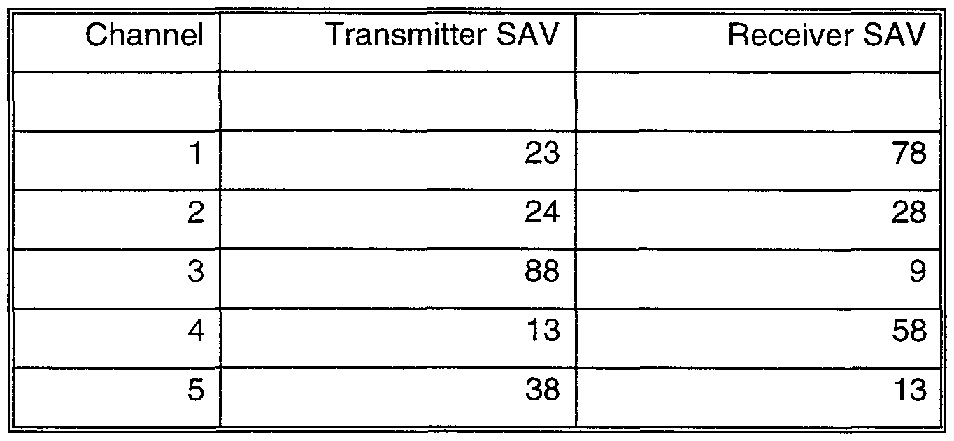
- the summed access values, or SAVs are simply the row or column totals for the transmitter (X-in the rows of the table) and receiver (R-in the columns of the table) interaction times and reflect the total demands on the particular resource, as measured in the arbitrary units of length.
- SAVs The summed access values, or SAVs, are simply the row or column totals for the transmitter (X-in the rows of the table) and receiver (R-in the columns of the table) interaction times and reflect the total demands on the particular resource, as measured in the arbitrary units of length.
- the resultant schedule regardless of the number or composition of the requests, applies to a future window of time increment of time with a duration of 150 units of time.
- the primary objective, judging by the SAVs, is to schedule some request involving Transmitter 3 and Receiver 1.
- the scheduler logic of the example finds a request involving Transmitter 3 and Receiver 1 which has a length of 16 units of time.
- Table 5 may be shown as schedule chart 1001 in Figure 10.
- Transmitter scheduled element 1002 and receiver scheduled element 1003 denote the scheduled tasks.
- the Request List must then somehow reflect the fact that this last request has been serviced. This modified Request List may now resemble that shown in Table 6.
- Event Table is effectively a (chronologically) sorted list of the scheduled requests from the Request List. For this reason, intermediate stages are not shown for each scheduling step.
- the scheduler logic of the example schedules a 1-to-2 communication instance request (that is a connection from Transmitter 1 to Receiver 2), and the tables are modified to Tables 11 and 12 as follows:
- the scheduler logic of the example next looks for a 2-to-5 communication instance request, but such a request was not made.
- Transmitter scheduled element 1002 and receiver scheduled element 1003 from Figure 10 have been denoted as scheduled elements 1102 and 1103, respectively, and have been joined by scheduled elements 1104 and 1105 (the 5-to-4 communication), 1106 and 1107 (the 1-to-2 communication), and 1108 and 1109 (the 4-to-5 communication).
- Advancing Time amounts to advancing to the next chronological finish.
- the Request List and SAV Table are now as shown in Tables 14 and 15.
- the scheduler logic of the example now looks for a 1-to-2 communication instance request, but the only 1-to-2 communication instance has already been scheduled, so the example look for a 1-to-5 communication instance request, which the example finds and schedules.
- the new SAV Table is then Table 17.
- the scheduler logic of the example looks for a 2-to-2 communication instance request, a 2-to-3 communication instance request, a 4-to-2 communication instance request and a 4- to-3 communication instance request before determining that it's time again to advance time.
- the example advances time from 15 to 16, at which time the SAV Table looks like Table 18.
- the tables, after the scheduler logic of the example advances time to Time 17, look like Tables 19, 20, and 21.
- the scheduler logic of the example now schedules a 5-to-3 communication instance, which is all that can be scheduled at this time. Time is then advanced to 27, then to 28, and the SAV Table looks like Table 25.
- the scheduler logic of the example schedules a 3-to-2 communication instance request and a 5-to-1 communication instance request, and advances time to 31 and then to 48, at which time the SAV Table becomes Table 26.
- Table 26 Intermediate Summed Access Value Table
- the scheduler logic of the example then schedules the 3-to-4 communication instance request and advances time to 49, giving Table 27 as a result.
- the scheduler logic of the example then books a 2-to-1 communication instance request and advances time to 67, giving Table 28.
- the scheduler logic of the example now books the 3-to-3 communication instance request and advances time to 73 as shown in Table 29.
- the scheduler logic of the example then books the 4-to-1 communication instance request, and advances time to 75, resulting in Table 30.
- the scheduler logic of the example now schedules the remaining 5-to-1 communication instance request, advances time to 91 , schedules the first 3-to-5 communication instance request, advances time to 94, then to 95, and schedules the final request, another 3-to-5 communication instance request.
- the resultant Event Table looks like Table 32.
- Transmitter scheduled element 1002 and receiver scheduled element 1003 from Figure 10 have been denoted as scheduled elements 1202 and 1203; scheduled elements 1104 and 1105, 1106 and 1107, and 1108 and 1109 from Figure 11 are denoted as scheduled elements 1204, 1205, 1206, 1207,1208, and 1209; and new elements 1216-1217 for the 1 -to-4 communication instance, 1214-1215 for the 5-to-2 communication instance, 1212-1213 for the 3-to-1 communication instance, 1220-1221 for the 3-to-2 communication instance, 1222- 1223 for the 5-to-1 communication instance, 1226-1227 for the 2-to-1 communication instance, 1224-1225 for the 3-to-4 communication instance, 1228-1229 for the 3-to-3 communication instance, 1230-1231 for the 4-to-1 communication instance, 1232-1233 for the 3-to-4 communication instance, 1234-1235 for the 5-to-1 communication instance, and 1238-1239 for the 3-to-5 communication instance are shown. Three of the interactions are shown without drawing element
- transmitter 3 the critical resource
- the scheduling process had applied to a 100 unit window of time increment of time rather than a 150 unit window of time increment , the very last request would have been precluded from being scheduled in this window of time increment , but would have been queued until the scheduling process was resumed for the next time window of time increment .
- the above example showed a list of requests where all of the requests had priority levels of 1. In one embodiment, four different priority levels are supported. All of the highest level requests are scheduled according to the logic before any of the other priority requests are even considered for scheduling.
- connection requests from the other three priorities are scheduled around the guaranteed requests already in the schedule.
- the process of calculating the window of time increment size is a little more complex, but the logic is essentially the same.
- the ACR value (or SAV) is still the predominant factor in deciding what gets scheduled when, connection requests between the same two concurrent resources are selected based on priority. This means, for example, that the ACR logic may elect to schedule a low priority 4- to-5 communication instance request before it schedules a medium priority 4-to-2 communication instance request, but never before it schedules a medium priority 4-to-5 communication instance request.
- the network scheduler in the preferred embodiment uses a minimum time increment of 256 units (with a scheduling window of time increment of over 25,000 units rather than the 150 unit window of time increment described above) to reduce the processing requirements. While this does have an obvious negative impact on scheduling efficiencies, there is also a less obvious positive impact. On the average, more resources are candidates for scheduling at each time increment as a result of having processed more finishes between increments. With more resources contending simultaneously, those resources with higher critical impact values are less likely to be preempted by some other resource which had simply finished earlier. The end result of this compromise is that compute cycles are saved, but bandwidth efficiencies aren't substantially impacted.
- requests greater than 1023 units are broken into 1000 unit "full” blocks and an optional "partial” block up to 1023 units in length.
- the Itineraries are themselves scheduled messages due to their varying, and potentially large, size.
- the Agendas (the messages used to collect the connection requests), however, are small and handled as fixed time connections (they are not literally scheduled).
- the scheduling pipeline used in the preferred embodiment involves collecting the agendas and scheduling the Itineraries in the first window of time increment, where the second, third, and fourth window of time increments are used as described (for scheduling the messages, conveying the schedule, and implementing the connections, respectively).
- FIG. 13 a more detailed representation of components respective to a member node 107, 108 is depicted. While Figure 13 reprises a number of elements of Figures 1 and 5, details of logic types are shown enabling concurrent transmission and receipt of messages respective to the other nodes.
- Transmit Logic 1301 and Receive Logic 1302 are shown for the Master Scheduler 106, with companion Transmit Logic 1319 and Receive Logic 1320 on member node 107 and further companion Transmit Logic 1321 and Receive Logic 1322 on member node 108.
- Pathways 1311 , 1305, and 1306 show vectored message paths outbound from message carrier 100 (with crossbar switch 516).
- Such messaging approaches are achievable with a context cycling computer such as has previously been discussed, enabling a particular node 107, 108, 106 to be engaged in highly interleaved transmission and receipt of messages. Further detail showing the local scheduler 1307, oscillator 1308, CPU 1309, and VCXO (Voltage Controlled Crystal Oscillator) 1309 is shown for node 107 along with the previously discussed local task list 1303 and local task schedule 1304 which have also been discussed in general.
- VCXO Voltage Controlled Crystal Oscillator
- FIG 14 focus is directed to three technologies which, when combined, illustrate a unique and valuable abstracted characterization of considerations in networking distributed, real-time computers to further put the nature of the present invention into full perspective.
- key technologies relate to Tight Synchronization between computers; Time Deterministic operation, including network communications; and Centralized Scheduling of distributed tasks, particularly those involving network communications.
- This diagram shows the interrelationships 1400 between the various technologies implemented in the preferred embodiment, with emphasis on those technologies considered critical to the implementation.
- the fundamental technologies which, when combined, provide an architecture amenable to real time computing in a distributed computing environment are (1 ) Time Deterministic Event Control 1422; (2) Tight
- Synchronization 1423 between systems and (3) Centralized Scheduling 1421 of the tasks critical to the operation of the real time systems in the distributed environment.
- the relationships between the technologies are shown using arrows, where the arrowheads point from the enabling technology to the enabled technology, and where the term "enabling" is loosely used here to describe an improvement in the utility of that technology, or in the simplicity of applying the technology. Note that many of the technologies are mutually beneficial, as depicted with a double headed arrow.
- the difficulty in achieving a desired level of synchronization is usually proportional to the extent that the communications are indeterminate.
- Time Determinism enables Time Determinism primarily in regards to failure recovery. It is difficult to manage the possible failure scenarios in the absence of redundancy, yet it is also difficult to manage failure recovery in a Time Deterministic system with passive redundancy. Time Determinism facilitates the use of Active Redundancy in that one of the biggest challenges to active redundancy is in assuring that all sides operate identically. Furthermore, with a Time Deterministic environment, a redundant element of a system can be diagnosed as dysfunctional simply by noting that the appropriate actions aren't occurring at the prescribed times.
- the time deterministic network involves communicating based on time between separate computing elements.
- the fact that the communications are scheduled based on time facilitates the employment of active redundancy.
- active redundancy there are two or more computers which are each executing identical logics via its own sequence of program instructions, exchanging the results of this execution, and then arbitrating to come to a result. Due to the fact that the data received by each computer must be shared with the other computer(s) executing the same logic prior to arbitrating this data, there must be some mechanism by which the time to begin the arbitration process in determined.
- the mechanism which has been chosen is to provide time synchronization between the redundant computers and schedule the tasks related to the communications based on time. In this way, there is known the time at which the arbitration task can begin.
- each member node 108, 107 is responsible for receiving the common clock signal; synchronizing to that common clock signal; receiving the local event table 114, 116 from the master scheduler 106 in network switch 501 ; formulating the task execution list based on the received local event table 1 14, 116 and merging in any additional tasks which are not described in the local event table 114, 116; executing the task execution list; generating the request list of communications; and transmitting the request list of communications to the master scheduler 106 in network switch 501.
- the clock signal is communicated as a message from the master scheduler 106 in network switch 501 to each of the member nodes 108, 107.
- the member node 108, 107 receives this clock signal in step 1501 , stamps the actual time of reception, and validates the integrity of this message.
- the validated message is used as an input to the process of synchronization and, in step 1502, the difference between the expected and actual times of time message receipt is optionally determined (optionally if the nature of the time message is a pulse instead of a data bearing message).
- Steps 1503 and 1504 - Each member node 108, 107 must now synchronize to the common clock signal.
- the process of performing this synchronization can be broken up into two separate tasks: first, in step 1503, the adjustment of a voltage controlled oscillator (1308) to a frequency which matches the source of the common clock signal and second, in step 1504, the alignment of the time such that the start of each time period which is defined by the common clock signal occurs at the same time in the member nodes 108, 107 as it does in the master scheduler 106 in network switch 501.
- Step 1505 Once the synchronization of a member node 108, 107 to the master scheduler 106 in network switch 501 is complete, the member node 108, 107 must receive the local event table 114, 116 from the master scheduler 106 in network switch 501.
- the local event table 114, 116 contains the schedule for the communications which are involving this member node. Note that the reception of the local event table 114, 116 itself is scheduled by the master scheduler 106 in network switch 501. Therefore, the first time that the node is to receive the local event table 114, 116 it must be available to receive that message at any possible time that the local event table 114, 116 might be received.
- Step 1506 - The next step for the member node 108, 107 is to formulate the task execution list.
- the task execution list is formulated from the local event table 114, 116 and the additional tasks which the member node 108, 107 must do which are not described in the local event table 114, 116.
- the local event table 114, 116 which is communicated from the master scheduler 106 in network switch 501 provides the timing associated with the transmission and reception tasks. In order to formulate the task execution list, the following sub-steps must be taken:
- Substep 1506A Adjust the start time received from the master scheduler 106 in network switch 501 to account for the propagation delay.
- the timing which is received from the master scheduler 106 in network switch 501 is relative to the master scheduler 106 in network switch 501.
- the member node 108, 107 is synchronized with the master scheduler 106 in network switch 501 , there is still an inherent delay in the propagation through the media being communicated. Either this delay must be accounted for by the master scheduler 106 in network switch 501 , the member node, or the communication window of time increment must be sufficiently large that the inherent delay is included as overhead in the time allotted to the connection. In the preferred embodiment, this delay is accounted for in the member node.
- Substep 1506B Schedule the tasks which are dependent on the communication tasks. There are tasks which must be scheduled prior to a transmission (for example, the transfer of the data to be transmitted from memory); there are also tasks which must be scheduled after a reception (for example, the arbitration of the data between the multiple, different sources in a redundant computing environment and the transfer of data to memory).
- the member node 108, 107 is responsible for the scheduling of these tasks.
- Substep 1506C Schedule the tasks which are neither described by the local event table 114, 116 nor are dependent on the communications. There are tasks which the member node 108, 107 must accomplish in addition to communication related tasks. These tasks may be for the operation of other I/O, localized display, etc.
- Step 1507 - The next step for the member node 108, 107 is to execute the task execution list.
- Each task in the list contains the task which is to be executed, the start time for the task, and any parameters which are necessary in order to successfully complete the task.
- Step 1508 - The member node 108, 107 can now formulate the communication request list, which is a list of the member nodes 108, 107 to which this member node 108, 107 is desiring to communicate.
- the information which is included in this communication request list is the source node identifier, destination node identifier, and the total length of the communication.
- Step 1509 This communication request list is communicated to the master scheduler 106 in network switch 501 for consideration in its scheduling. At this point, the member node 108, 107 has performed all of the necessary functions in a particular time period.
- the next step 1510 is to determine whether or not it is time to receive the next reference moment message. If it is, then the entire process repeats itself starting with the very first step 1501 of receiving the reference moment message. If it is not time to receive the next reference moment message, then the logic of the member node may forward to step 1505.
- Figure 16 presents the general data flow diagram 130 of Figure 1 as a data flow diagram 1600 where communications are effected via radio frequency means and transmissions 1601 , 1602, and 1603 are effected via radio frequency transmitters and receivers.
- the present invention is enabled through use of machines which are considered as a special purpose computers created in one embodiment by combining a computer with computer program code (alternatively termed, for example, software or logic, where logic denotes software in and for execution by an enabling system of electrical circuitry) directed to the particular function of process control so that, when connected to an electrical power source, powered by electricity, and activated to execute its computer program code (software), the special purpose computer executes the particular function related to the present invention pursuant to the instructions from the computer program code.
- computer program code alternatively termed, for example, software or logic, where logic denotes software in and for execution by an enabling system of electrical circuitry
- the computer has electrically activated components denoted as a central processing unit, at least one physical memory connected to the central processing unit, an optional input keyboard connected to the central processing unit, an optional output display (which can include, without limitation, a printer, printing terminal where output is printed on paper, cathode ray tube monitor, and/or flat panel monitor) connected to the central processing unit, a computer clock pulse generator, and a connection to electrical power for energizing all of the electrically activated components of the computer.
- a central processing unit at least one physical memory connected to the central processing unit
- an optional input keyboard connected to the central processing unit
- an optional output display which can include, without limitation, a printer, printing terminal where output is printed on paper, cathode ray tube monitor, and/or flat panel monitor
- a computer clock pulse generator which can include, without limitation, a printer, printing terminal where output is printed on paper, cathode ray tube monitor, and/or flat panel monitor
- the central processor further has a control bus and specific computer circuits for either temporarily holding data (for example, a register or an accumulator) or for executing a fundamental data processing operation (for example, an addition circuit); the specific computer circuits are connected in communication to the control bus through latching circuits which can individually be in either a conducting (communicating) or non-conducting (non-communicating) configuration; the collective configurations of all the latching circuits at a particular moment define a particular state of the central processor; and the state of the central processor is respectively modified and changed as the individual instructions of the computer program code are sequentially accessed by the central processing unit and output from the clock pulse generator is directed to the latches.
- data for example, a register or an accumulator
- a fundamental data processing operation for example, an addition circuit
- latching circuits which can individually be in either a conducting (communicating) or non-conducting (non-communicating) configuration
- the collective configurations of all the latching circuits at a particular moment define a
- the computer optionally also has computer program code in the form of a commercially available operating system which functions as a computer program code platform for enabling the execution of the special purpose computer program code directed to the particular function of the present invention.
- the present invention in this embodiment is implemented in the preferred embodiment by and through a plurality of computers which have been programmed to contribute to technology by performing the specifically useful purpose and practical application of the described system; each computer functions as a medium for realizing the functionality provided by the computer program code's functionality.
- some communication linkages within an extended form of the special purpose computer may be implemented by electrical, optical, or radio-frequency signal communication interfaces and communication media which collectively use electrically-powered transmitter and receiver components which are directly or indirectly linked to at least one central processing unit.
- the computer program code resident within a computer provides at least one component part of that machine.
- the computer program code may be in the form of, without limitation, inter-linked modules, routines and subroutines, program objects, and/or installed interactive processes.
- computer program code may be at least partially expressed in hardwired circuitry reminiscent of traditional hardwired gate arrangements which execute simplified logical scenarios without need for a clock pulse.
- ASIC application specific integrated circuitry
Abstract
Description


Claims
Priority Applications (5)
| Application Number | Priority Date | Filing Date | Title |
|---|---|---|---|
| EP99914169A EP1084470B1 (en) | 1998-05-26 | 1999-03-26 | Distributed computing environment using real-time scheduling logic and time deterministic architecture |
| DE69909791T DE69909791T2 (en) | 1998-05-26 | 1999-03-26 | DISTRIBUTED COMPUTER ENVIRONMENT WITH REAL-TIME SEQUENCE LOGIC AND TIME-DETERMINIST ARCHITECTURE |
| CA002331860A CA2331860A1 (en) | 1998-05-26 | 1999-03-26 | Distributed computing environment using real-time scheduling logic and time deterministic architecture |
| JP2000551319A JP2002517035A (en) | 1998-05-26 | 1999-03-26 | Distributed computing environment using real-time scheduling logic and time-deterministic architecture |
| AT99914169T ATE245833T1 (en) | 1998-05-26 | 1999-03-26 | DISTRIBUTED COMPUTING ENVIRONMENT WITH REAL-TIME SEQUENCE LOGIC AND TIME-DETERMINISTIC ARCHITECTURE |
Applications Claiming Priority (2)
| Application Number | Priority Date | Filing Date | Title |
|---|---|---|---|
| US8673798P | 1998-05-26 | 1998-05-26 | |
| US60/086,737 | 1998-05-26 |
Publications (1)
| Publication Number | Publication Date |
|---|---|
| WO1999061985A1 true WO1999061985A1 (en) | 1999-12-02 |
Family
ID=22200563
Family Applications (1)
| Application Number | Title | Priority Date | Filing Date |
|---|---|---|---|
| PCT/US1999/006634 WO1999061985A1 (en) | 1998-05-26 | 1999-03-26 | Distributed computing environment using real-time scheduling logic and time deterministic architecture |
Country Status (7)
| Country | Link |
|---|---|
| EP (1) | EP1084470B1 (en) |
| JP (1) | JP2002517035A (en) |
| CN (1) | CN1303497A (en) |
| AT (1) | ATE245833T1 (en) |
| CA (1) | CA2331860A1 (en) |
| DE (1) | DE69909791T2 (en) |
| WO (1) | WO1999061985A1 (en) |
Cited By (49)
| Publication number | Priority date | Publication date | Assignee | Title |
|---|---|---|---|---|
| EP1654614A2 (en) * | 2003-07-28 | 2006-05-10 | Sonos, Inc. | System and method for synchronizing operations among a plurality of independently clocked digital data processing devices |
| CN100362522C (en) * | 2006-03-31 | 2008-01-16 | 北京飞天诚信科技有限公司 | Real time clock correcting method in soft ware protecter |
| US7331048B2 (en) | 2003-04-04 | 2008-02-12 | International Business Machines Corporation | Backfill scheduling of applications based on data of the applications |
| US8588949B2 (en) | 2003-07-28 | 2013-11-19 | Sonos, Inc. | Method and apparatus for adjusting volume levels in a multi-zone system |
| US8775546B2 (en) | 2006-11-22 | 2014-07-08 | Sonos, Inc | Systems and methods for synchronizing operations among a plurality of independently clocked digital data processing devices that independently source digital data |
| US9207905B2 (en) | 2003-07-28 | 2015-12-08 | Sonos, Inc. | Method and apparatus for providing synchrony group status information |
| US9288596B2 (en) | 2013-09-30 | 2016-03-15 | Sonos, Inc. | Coordinator device for paired or consolidated players |
| US9300647B2 (en) | 2014-01-15 | 2016-03-29 | Sonos, Inc. | Software application and zones |
| US9313591B2 (en) | 2014-01-27 | 2016-04-12 | Sonos, Inc. | Audio synchronization among playback devices using offset information |
| US9374607B2 (en) | 2012-06-26 | 2016-06-21 | Sonos, Inc. | Media playback system with guest access |
| US9654545B2 (en) | 2013-09-30 | 2017-05-16 | Sonos, Inc. | Group coordinator device selection |
| US9679054B2 (en) | 2014-03-05 | 2017-06-13 | Sonos, Inc. | Webpage media playback |
| US9690540B2 (en) | 2014-09-24 | 2017-06-27 | Sonos, Inc. | Social media queue |
| US9723038B2 (en) | 2014-09-24 | 2017-08-01 | Sonos, Inc. | Social media connection recommendations based on playback information |
| US9720576B2 (en) | 2013-09-30 | 2017-08-01 | Sonos, Inc. | Controlling and displaying zones in a multi-zone system |
| US9729115B2 (en) | 2012-04-27 | 2017-08-08 | Sonos, Inc. | Intelligently increasing the sound level of player |
| US9749760B2 (en) | 2006-09-12 | 2017-08-29 | Sonos, Inc. | Updating zone configuration in a multi-zone media system |
| US9756424B2 (en) | 2006-09-12 | 2017-09-05 | Sonos, Inc. | Multi-channel pairing in a media system |
| US9766853B2 (en) | 2006-09-12 | 2017-09-19 | Sonos, Inc. | Pair volume control |
| US9781513B2 (en) | 2014-02-06 | 2017-10-03 | Sonos, Inc. | Audio output balancing |
| US9787550B2 (en) | 2004-06-05 | 2017-10-10 | Sonos, Inc. | Establishing a secure wireless network with a minimum human intervention |
| US9794707B2 (en) | 2014-02-06 | 2017-10-17 | Sonos, Inc. | Audio output balancing |
| US9860286B2 (en) | 2014-09-24 | 2018-01-02 | Sonos, Inc. | Associating a captured image with a media item |
| US9874997B2 (en) | 2014-08-08 | 2018-01-23 | Sonos, Inc. | Social playback queues |
| US9886234B2 (en) | 2016-01-28 | 2018-02-06 | Sonos, Inc. | Systems and methods of distributing audio to one or more playback devices |
| US9959087B2 (en) | 2014-09-24 | 2018-05-01 | Sonos, Inc. | Media item context from social media |
| US9961656B2 (en) | 2013-04-29 | 2018-05-01 | Google Technology Holdings LLC | Systems and methods for syncronizing multiple electronic devices |
| US9977561B2 (en) | 2004-04-01 | 2018-05-22 | Sonos, Inc. | Systems, methods, apparatus, and articles of manufacture to provide guest access |
| US10055003B2 (en) | 2013-09-30 | 2018-08-21 | Sonos, Inc. | Playback device operations based on battery level |
| US10097893B2 (en) | 2013-01-23 | 2018-10-09 | Sonos, Inc. | Media experience social interface |
| US10306364B2 (en) | 2012-09-28 | 2019-05-28 | Sonos, Inc. | Audio processing adjustments for playback devices based on determined characteristics of audio content |
| US10360290B2 (en) | 2014-02-05 | 2019-07-23 | Sonos, Inc. | Remote creation of a playback queue for a future event |
| US10587693B2 (en) | 2014-04-01 | 2020-03-10 | Sonos, Inc. | Mirrored queues |
| US10621310B2 (en) | 2014-05-12 | 2020-04-14 | Sonos, Inc. | Share restriction for curated playlists |
| US10620988B2 (en) | 2010-12-16 | 2020-04-14 | Et International, Inc. | Distributed computing architecture |
| US10645130B2 (en) | 2014-09-24 | 2020-05-05 | Sonos, Inc. | Playback updates |
| US10873612B2 (en) | 2014-09-24 | 2020-12-22 | Sonos, Inc. | Indicating an association between a social-media account and a media playback system |
| US11106424B2 (en) | 2003-07-28 | 2021-08-31 | Sonos, Inc. | Synchronizing operations among a plurality of independently clocked digital data processing devices |
| US11106425B2 (en) | 2003-07-28 | 2021-08-31 | Sonos, Inc. | Synchronizing operations among a plurality of independently clocked digital data processing devices |
| US11190564B2 (en) | 2014-06-05 | 2021-11-30 | Sonos, Inc. | Multimedia content distribution system and method |
| US11223661B2 (en) | 2014-09-24 | 2022-01-11 | Sonos, Inc. | Social media connection recommendations based on playback information |
| US11265652B2 (en) | 2011-01-25 | 2022-03-01 | Sonos, Inc. | Playback device pairing |
| US11294618B2 (en) | 2003-07-28 | 2022-04-05 | Sonos, Inc. | Media player system |
| US11403062B2 (en) | 2015-06-11 | 2022-08-02 | Sonos, Inc. | Multiple groupings in a playback system |
| US11429343B2 (en) | 2011-01-25 | 2022-08-30 | Sonos, Inc. | Stereo playback configuration and control |
| US11481182B2 (en) | 2016-10-17 | 2022-10-25 | Sonos, Inc. | Room association based on name |
| US11650784B2 (en) | 2003-07-28 | 2023-05-16 | Sonos, Inc. | Adjusting volume levels |
| US11894975B2 (en) | 2004-06-05 | 2024-02-06 | Sonos, Inc. | Playback device connection |
| US11960704B2 (en) | 2022-06-13 | 2024-04-16 | Sonos, Inc. | Social playback queues |
Families Citing this family (12)
| Publication number | Priority date | Publication date | Assignee | Title |
|---|---|---|---|---|
| KR100684191B1 (en) * | 2002-10-23 | 2007-02-22 | 샤프 가부시키가이샤 | Communication management method, central control station, communication station, communication management program, and computer-readable recording medium storing communication management program |
| US7483898B2 (en) * | 2004-06-14 | 2009-01-27 | Microsoft Corporation | System and method for auditing a network |
| US7496099B2 (en) * | 2004-07-30 | 2009-02-24 | Fisher-Rosemount Systems, Inc. | Communication controller for coordinating transmission of scheduled and unscheduled messages |
| CN101132270B (en) * | 2007-08-02 | 2010-09-08 | 北京航空航天大学 | Multi-node coordinated time consistency management method |
| CN102457370A (en) * | 2010-10-27 | 2012-05-16 | 金蝶软件(中国)有限公司 | Virtual cluster synchronization signal generating method, device and system |
| EP2657797B1 (en) | 2012-04-27 | 2017-01-18 | Siemens Aktiengesellschaft | Method for operating a redundant automation system |
| WO2014046642A1 (en) * | 2012-09-18 | 2014-03-27 | Siemens Aktiengesellschaft | Multiple programmable logic controller simulator |
| AT514444A2 (en) * | 2013-06-24 | 2015-01-15 | Fts Computertechnik Gmbh | Method and device for timely data transfer to the cyclic tasks in a distributed real-time system |
| CN103530742B (en) * | 2013-10-28 | 2019-01-29 | 金蝶软件(中国)有限公司 | Improve the method and device of scheduling arithmetic speed |
| CN107168790B (en) * | 2017-03-31 | 2020-04-03 | 北京奇艺世纪科技有限公司 | Job scheduling method and device |
| CN110535706B (en) * | 2019-09-02 | 2022-03-01 | 成都吉胜科技有限责任公司 | Automatic cooperative scheduling method based on local area network |
| CN112711235B (en) * | 2020-12-29 | 2022-05-10 | 浙江中控技术股份有限公司 | Method for self-adapting token scheduling time of industrial control system |
Citations (2)
| Publication number | Priority date | Publication date | Assignee | Title |
|---|---|---|---|---|
| EP0183877A1 (en) * | 1984-11-30 | 1986-06-11 | Inmos Limited | Microcomputer for time dependent processes |
| EP0250011A2 (en) * | 1982-11-26 | 1987-12-23 | Inmos Limited | Scheduling of concurrent processes in a microcomputer system |
-
1999
- 1999-03-26 WO PCT/US1999/006634 patent/WO1999061985A1/en active IP Right Grant
- 1999-03-26 DE DE69909791T patent/DE69909791T2/en not_active Expired - Fee Related
- 1999-03-26 JP JP2000551319A patent/JP2002517035A/en active Pending
- 1999-03-26 AT AT99914169T patent/ATE245833T1/en not_active IP Right Cessation
- 1999-03-26 EP EP99914169A patent/EP1084470B1/en not_active Expired - Lifetime
- 1999-03-26 CA CA002331860A patent/CA2331860A1/en not_active Abandoned
- 1999-03-26 CN CN99806614.1A patent/CN1303497A/en active Pending
Patent Citations (2)
| Publication number | Priority date | Publication date | Assignee | Title |
|---|---|---|---|---|
| EP0250011A2 (en) * | 1982-11-26 | 1987-12-23 | Inmos Limited | Scheduling of concurrent processes in a microcomputer system |
| EP0183877A1 (en) * | 1984-11-30 | 1986-06-11 | Inmos Limited | Microcomputer for time dependent processes |
Non-Patent Citations (2)
| Title |
|---|
| RAMAKRISHNAN K V: "AN EVENT SCHEDULER FOR CONTROL APPLICATIONS", EDN ELECTRICAL DESIGN NEWS, vol. 41, no. 12, 6 June 1996 (1996-06-06), pages 155 - 158, 160, 16, XP000622016, ISSN: 0012-7515 * |
| SHIN K G ET AL: "REAL-TIME COMPUTING: A NEW DISCIPLINE OF COMPUTER SCIENCE AND ENGINEERING", PROCEEDINGS OF THE IEEE, vol. 82, no. 1, 1 January 1994 (1994-01-01), pages 6 - 23, XP000435878, ISSN: 0018-9219 * |
Cited By (218)
| Publication number | Priority date | Publication date | Assignee | Title |
|---|---|---|---|---|
| US7331048B2 (en) | 2003-04-04 | 2008-02-12 | International Business Machines Corporation | Backfill scheduling of applications based on data of the applications |
| US8136115B2 (en) | 2003-04-04 | 2012-03-13 | International Business Machines Corporation | Backfill scheduling of applications based on data of the applications |
| US10228902B2 (en) | 2003-07-28 | 2019-03-12 | Sonos, Inc. | Playback device |
| US10747496B2 (en) | 2003-07-28 | 2020-08-18 | Sonos, Inc. | Playback device |
| US10754613B2 (en) | 2003-07-28 | 2020-08-25 | Sonos, Inc. | Audio master selection |
| US8234395B2 (en) | 2003-07-28 | 2012-07-31 | Sonos, Inc. | System and method for synchronizing operations among a plurality of independently clocked digital data processing devices |
| EP2648111A1 (en) * | 2003-07-28 | 2013-10-09 | Sonos, Inc. | System and method for synchronizing operations among a plurality of independently clocked digital data processing devices |
| US8588949B2 (en) | 2003-07-28 | 2013-11-19 | Sonos, Inc. | Method and apparatus for adjusting volume levels in a multi-zone system |
| US8689036B2 (en) | 2003-07-28 | 2014-04-01 | Sonos, Inc | Systems and methods for synchronizing operations among a plurality of independently clocked digital data processing devices without a voltage controlled crystal oscillator |
| EP2713281A1 (en) * | 2003-07-28 | 2014-04-02 | Sonos, Inc. | System and method for synchronizing operations among a plurality of independently clocked digital data processing devices |
| US10754612B2 (en) | 2003-07-28 | 2020-08-25 | Sonos, Inc. | Playback device volume control |
| US8938637B2 (en) | 2003-07-28 | 2015-01-20 | Sonos, Inc | Systems and methods for synchronizing operations among a plurality of independently clocked digital data processing devices without a voltage controlled crystal oscillator |
| EP2866152A1 (en) * | 2003-07-28 | 2015-04-29 | Sonos, Inc. | System and method for synchronizing operations among a plurality of independently clocked digital data processing devices |
| US9141645B2 (en) | 2003-07-28 | 2015-09-22 | Sonos, Inc. | User interfaces for controlling and manipulating groupings in a multi-zone media system |
| US9158327B2 (en) | 2003-07-28 | 2015-10-13 | Sonos, Inc. | Method and apparatus for skipping tracks in a multi-zone system |
| US9164533B2 (en) | 2003-07-28 | 2015-10-20 | Sonos, Inc. | Method and apparatus for obtaining audio content and providing the audio content to a plurality of audio devices in a multi-zone system |
| US9164532B2 (en) | 2003-07-28 | 2015-10-20 | Sonos, Inc. | Method and apparatus for displaying zones in a multi-zone system |
| US9164531B2 (en) | 2003-07-28 | 2015-10-20 | Sonos, Inc. | System and method for synchronizing operations among a plurality of independently clocked digital data processing devices |
| US9170600B2 (en) | 2003-07-28 | 2015-10-27 | Sonos, Inc. | Method and apparatus for providing synchrony group status information |
| US9176519B2 (en) | 2003-07-28 | 2015-11-03 | Sonos, Inc. | Method and apparatus for causing a device to join a synchrony group |
| US9176520B2 (en) | 2003-07-28 | 2015-11-03 | Sonos, Inc. | Obtaining and transmitting audio |
| US9182777B2 (en) | 2003-07-28 | 2015-11-10 | Sonos, Inc. | System and method for synchronizing operations among a plurality of independently clocked digital data processing devices |
| US9189010B2 (en) | 2003-07-28 | 2015-11-17 | Sonos, Inc. | Method and apparatus to receive, play, and provide audio content in a multi-zone system |
| US9189011B2 (en) | 2003-07-28 | 2015-11-17 | Sonos, Inc. | Method and apparatus for providing audio and playback timing information to a plurality of networked audio devices |
| US9195258B2 (en) | 2003-07-28 | 2015-11-24 | Sonos, Inc. | System and method for synchronizing operations among a plurality of independently clocked digital data processing devices |
| US9207905B2 (en) | 2003-07-28 | 2015-12-08 | Sonos, Inc. | Method and apparatus for providing synchrony group status information |
| US9213357B2 (en) | 2003-07-28 | 2015-12-15 | Sonos, Inc. | Obtaining content from remote source for playback |
| US10613817B2 (en) | 2003-07-28 | 2020-04-07 | Sonos, Inc. | Method and apparatus for displaying a list of tracks scheduled for playback by a synchrony group |
| US9218017B2 (en) | 2003-07-28 | 2015-12-22 | Sonos, Inc. | Systems and methods for controlling media players in a synchrony group |
| US11301207B1 (en) | 2003-07-28 | 2022-04-12 | Sonos, Inc. | Playback device |
| US10949163B2 (en) | 2003-07-28 | 2021-03-16 | Sonos, Inc. | Playback device |
| US10956119B2 (en) | 2003-07-28 | 2021-03-23 | Sonos, Inc. | Playback device |
| US9348354B2 (en) | 2003-07-28 | 2016-05-24 | Sonos, Inc. | Systems and methods for synchronizing operations among a plurality of independently clocked digital data processing devices without a voltage controlled crystal oscillator |
| US9354656B2 (en) | 2003-07-28 | 2016-05-31 | Sonos, Inc. | Method and apparatus for dynamic channelization device switching in a synchrony group |
| US10545723B2 (en) | 2003-07-28 | 2020-01-28 | Sonos, Inc. | Playback device |
| US10445054B2 (en) | 2003-07-28 | 2019-10-15 | Sonos, Inc. | Method and apparatus for switching between a directly connected and a networked audio source |
| US11650784B2 (en) | 2003-07-28 | 2023-05-16 | Sonos, Inc. | Adjusting volume levels |
| US11635935B2 (en) | 2003-07-28 | 2023-04-25 | Sonos, Inc. | Adjusting volume levels |
| US9658820B2 (en) | 2003-07-28 | 2017-05-23 | Sonos, Inc. | Resuming synchronous playback of content |
| US11625221B2 (en) | 2003-07-28 | 2023-04-11 | Sonos, Inc | Synchronizing playback by media playback devices |
| US11556305B2 (en) | 2003-07-28 | 2023-01-17 | Sonos, Inc. | Synchronizing playback by media playback devices |
| US11550536B2 (en) | 2003-07-28 | 2023-01-10 | Sonos, Inc. | Adjusting volume levels |
| US11550539B2 (en) | 2003-07-28 | 2023-01-10 | Sonos, Inc. | Playback device |
| US10387102B2 (en) | 2003-07-28 | 2019-08-20 | Sonos, Inc. | Playback device grouping |
| US9727304B2 (en) | 2003-07-28 | 2017-08-08 | Sonos, Inc. | Obtaining content from direct source and other source |
| US10365884B2 (en) | 2003-07-28 | 2019-07-30 | Sonos, Inc. | Group volume control |
| US9727302B2 (en) | 2003-07-28 | 2017-08-08 | Sonos, Inc. | Obtaining content from remote source for playback |
| US9727303B2 (en) | 2003-07-28 | 2017-08-08 | Sonos, Inc. | Resuming synchronous playback of content |
| US9733893B2 (en) | 2003-07-28 | 2017-08-15 | Sonos, Inc. | Obtaining and transmitting audio |
| US9733891B2 (en) | 2003-07-28 | 2017-08-15 | Sonos, Inc. | Obtaining content from local and remote sources for playback |
| US9734242B2 (en) | 2003-07-28 | 2017-08-15 | Sonos, Inc. | Systems and methods for synchronizing operations among a plurality of independently clocked digital data processing devices that independently source digital data |
| US9733892B2 (en) | 2003-07-28 | 2017-08-15 | Sonos, Inc. | Obtaining content based on control by multiple controllers |
| US9740453B2 (en) | 2003-07-28 | 2017-08-22 | Sonos, Inc. | Obtaining content from multiple remote sources for playback |
| US10359987B2 (en) | 2003-07-28 | 2019-07-23 | Sonos, Inc. | Adjusting volume levels |
| US10963215B2 (en) | 2003-07-28 | 2021-03-30 | Sonos, Inc. | Media playback device and system |
| US10970034B2 (en) | 2003-07-28 | 2021-04-06 | Sonos, Inc. | Audio distributor selection |
| US9778900B2 (en) | 2003-07-28 | 2017-10-03 | Sonos, Inc. | Causing a device to join a synchrony group |
| US9778898B2 (en) | 2003-07-28 | 2017-10-03 | Sonos, Inc. | Resynchronization of playback devices |
| US10324684B2 (en) | 2003-07-28 | 2019-06-18 | Sonos, Inc. | Playback device synchrony group states |
| US9778897B2 (en) | 2003-07-28 | 2017-10-03 | Sonos, Inc. | Ceasing playback among a plurality of playback devices |
| US10303431B2 (en) | 2003-07-28 | 2019-05-28 | Sonos, Inc. | Synchronizing operations among a plurality of independently clocked digital data processing devices |
| US10303432B2 (en) | 2003-07-28 | 2019-05-28 | Sonos, Inc | Playback device |
| US10296283B2 (en) | 2003-07-28 | 2019-05-21 | Sonos, Inc. | Directing synchronous playback between zone players |
| US10289380B2 (en) | 2003-07-28 | 2019-05-14 | Sonos, Inc. | Playback device |
| US10282164B2 (en) | 2003-07-28 | 2019-05-07 | Sonos, Inc. | Synchronizing operations among a plurality of independently clocked digital data processing devices |
| EP1654614A4 (en) * | 2003-07-28 | 2009-10-28 | Sonos Inc | System and method for synchronizing operations among a plurality of independently clocked digital data processing devices |
| EP1654614A2 (en) * | 2003-07-28 | 2006-05-10 | Sonos, Inc. | System and method for synchronizing operations among a plurality of independently clocked digital data processing devices |
| US9213356B2 (en) | 2003-07-28 | 2015-12-15 | Sonos, Inc. | Method and apparatus for synchrony group control via one or more independent controllers |
| US10216473B2 (en) | 2003-07-28 | 2019-02-26 | Sonos, Inc. | Playback device synchrony group states |
| US10209953B2 (en) | 2003-07-28 | 2019-02-19 | Sonos, Inc. | Playback device |
| US11294618B2 (en) | 2003-07-28 | 2022-04-05 | Sonos, Inc. | Media player system |
| US10185540B2 (en) | 2003-07-28 | 2019-01-22 | Sonos, Inc. | Playback device |
| US10185541B2 (en) | 2003-07-28 | 2019-01-22 | Sonos, Inc. | Playback device |
| US11200025B2 (en) | 2003-07-28 | 2021-12-14 | Sonos, Inc. | Playback device |
| US11132170B2 (en) | 2003-07-28 | 2021-09-28 | Sonos, Inc. | Adjusting volume levels |
| US10175930B2 (en) | 2003-07-28 | 2019-01-08 | Sonos, Inc. | Method and apparatus for playback by a synchrony group |
| US10175932B2 (en) | 2003-07-28 | 2019-01-08 | Sonos, Inc. | Obtaining content from direct source and remote source |
| US10031715B2 (en) | 2003-07-28 | 2018-07-24 | Sonos, Inc. | Method and apparatus for dynamic master device switching in a synchrony group |
| US11106425B2 (en) | 2003-07-28 | 2021-08-31 | Sonos, Inc. | Synchronizing operations among a plurality of independently clocked digital data processing devices |
| US10157033B2 (en) | 2003-07-28 | 2018-12-18 | Sonos, Inc. | Method and apparatus for switching between a directly connected and a networked audio source |
| US11106424B2 (en) | 2003-07-28 | 2021-08-31 | Sonos, Inc. | Synchronizing operations among a plurality of independently clocked digital data processing devices |
| US11080001B2 (en) | 2003-07-28 | 2021-08-03 | Sonos, Inc. | Concurrent transmission and playback of audio information |
| US10157035B2 (en) | 2003-07-28 | 2018-12-18 | Sonos, Inc. | Switching between a directly connected and a networked audio source |
| US10120638B2 (en) | 2003-07-28 | 2018-11-06 | Sonos, Inc. | Synchronizing operations among a plurality of independently clocked digital data processing devices |
| US10157034B2 (en) | 2003-07-28 | 2018-12-18 | Sonos, Inc. | Clock rate adjustment in a multi-zone system |
| US10133536B2 (en) | 2003-07-28 | 2018-11-20 | Sonos, Inc. | Method and apparatus for adjusting volume in a synchrony group |
| US10146498B2 (en) | 2003-07-28 | 2018-12-04 | Sonos, Inc. | Disengaging and engaging zone players |
| US10140085B2 (en) | 2003-07-28 | 2018-11-27 | Sonos, Inc. | Playback device operating states |
| US11907610B2 (en) | 2004-04-01 | 2024-02-20 | Sonos, Inc. | Guess access to a media playback system |
| US10983750B2 (en) | 2004-04-01 | 2021-04-20 | Sonos, Inc. | Guest access to a media playback system |
| US11467799B2 (en) | 2004-04-01 | 2022-10-11 | Sonos, Inc. | Guest access to a media playback system |
| US9977561B2 (en) | 2004-04-01 | 2018-05-22 | Sonos, Inc. | Systems, methods, apparatus, and articles of manufacture to provide guest access |
| US11894975B2 (en) | 2004-06-05 | 2024-02-06 | Sonos, Inc. | Playback device connection |
| US11909588B2 (en) | 2004-06-05 | 2024-02-20 | Sonos, Inc. | Wireless device connection |
| US10097423B2 (en) | 2004-06-05 | 2018-10-09 | Sonos, Inc. | Establishing a secure wireless network with minimum human intervention |
| US9960969B2 (en) | 2004-06-05 | 2018-05-01 | Sonos, Inc. | Playback device connection |
| US11456928B2 (en) | 2004-06-05 | 2022-09-27 | Sonos, Inc. | Playback device connection |
| US10965545B2 (en) | 2004-06-05 | 2021-03-30 | Sonos, Inc. | Playback device connection |
| US10541883B2 (en) | 2004-06-05 | 2020-01-21 | Sonos, Inc. | Playback device connection |
| US11025509B2 (en) | 2004-06-05 | 2021-06-01 | Sonos, Inc. | Playback device connection |
| US10439896B2 (en) | 2004-06-05 | 2019-10-08 | Sonos, Inc. | Playback device connection |
| US9866447B2 (en) | 2004-06-05 | 2018-01-09 | Sonos, Inc. | Indicator on a network device |
| US9787550B2 (en) | 2004-06-05 | 2017-10-10 | Sonos, Inc. | Establishing a secure wireless network with a minimum human intervention |
| US10979310B2 (en) | 2004-06-05 | 2021-04-13 | Sonos, Inc. | Playback device connection |
| CN100362522C (en) * | 2006-03-31 | 2008-01-16 | 北京飞天诚信科技有限公司 | Real time clock correcting method in soft ware protecter |
| US10228898B2 (en) | 2006-09-12 | 2019-03-12 | Sonos, Inc. | Identification of playback device and stereo pair names |
| US10469966B2 (en) | 2006-09-12 | 2019-11-05 | Sonos, Inc. | Zone scene management |
| US10136218B2 (en) | 2006-09-12 | 2018-11-20 | Sonos, Inc. | Playback device pairing |
| US10306365B2 (en) | 2006-09-12 | 2019-05-28 | Sonos, Inc. | Playback device pairing |
| US9860657B2 (en) | 2006-09-12 | 2018-01-02 | Sonos, Inc. | Zone configurations maintained by playback device |
| US11388532B2 (en) | 2006-09-12 | 2022-07-12 | Sonos, Inc. | Zone scene activation |
| US10848885B2 (en) | 2006-09-12 | 2020-11-24 | Sonos, Inc. | Zone scene management |
| US9756424B2 (en) | 2006-09-12 | 2017-09-05 | Sonos, Inc. | Multi-channel pairing in a media system |
| US9749760B2 (en) | 2006-09-12 | 2017-08-29 | Sonos, Inc. | Updating zone configuration in a multi-zone media system |
| US9766853B2 (en) | 2006-09-12 | 2017-09-19 | Sonos, Inc. | Pair volume control |
| US11540050B2 (en) | 2006-09-12 | 2022-12-27 | Sonos, Inc. | Playback device pairing |
| US11385858B2 (en) | 2006-09-12 | 2022-07-12 | Sonos, Inc. | Predefined multi-channel listening environment |
| US10448159B2 (en) | 2006-09-12 | 2019-10-15 | Sonos, Inc. | Playback device pairing |
| US11082770B2 (en) | 2006-09-12 | 2021-08-03 | Sonos, Inc. | Multi-channel pairing in a media system |
| US10966025B2 (en) | 2006-09-12 | 2021-03-30 | Sonos, Inc. | Playback device pairing |
| US9813827B2 (en) | 2006-09-12 | 2017-11-07 | Sonos, Inc. | Zone configuration based on playback selections |
| US10897679B2 (en) | 2006-09-12 | 2021-01-19 | Sonos, Inc. | Zone scene management |
| US10028056B2 (en) | 2006-09-12 | 2018-07-17 | Sonos, Inc. | Multi-channel pairing in a media system |
| US10555082B2 (en) | 2006-09-12 | 2020-02-04 | Sonos, Inc. | Playback device pairing |
| US9928026B2 (en) | 2006-09-12 | 2018-03-27 | Sonos, Inc. | Making and indicating a stereo pair |
| US8775546B2 (en) | 2006-11-22 | 2014-07-08 | Sonos, Inc | Systems and methods for synchronizing operations among a plurality of independently clocked digital data processing devices that independently source digital data |
| US10620988B2 (en) | 2010-12-16 | 2020-04-14 | Et International, Inc. | Distributed computing architecture |
| US11265652B2 (en) | 2011-01-25 | 2022-03-01 | Sonos, Inc. | Playback device pairing |
| US11758327B2 (en) | 2011-01-25 | 2023-09-12 | Sonos, Inc. | Playback device pairing |
| US11429343B2 (en) | 2011-01-25 | 2022-08-30 | Sonos, Inc. | Stereo playback configuration and control |
| US10063202B2 (en) | 2012-04-27 | 2018-08-28 | Sonos, Inc. | Intelligently modifying the gain parameter of a playback device |
| US9729115B2 (en) | 2012-04-27 | 2017-08-08 | Sonos, Inc. | Intelligently increasing the sound level of player |
| US10720896B2 (en) | 2012-04-27 | 2020-07-21 | Sonos, Inc. | Intelligently modifying the gain parameter of a playback device |
| US9374607B2 (en) | 2012-06-26 | 2016-06-21 | Sonos, Inc. | Media playback system with guest access |
| US10306364B2 (en) | 2012-09-28 | 2019-05-28 | Sonos, Inc. | Audio processing adjustments for playback devices based on determined characteristics of audio content |
| US10097893B2 (en) | 2013-01-23 | 2018-10-09 | Sonos, Inc. | Media experience social interface |
| US10587928B2 (en) | 2013-01-23 | 2020-03-10 | Sonos, Inc. | Multiple household management |
| US11889160B2 (en) | 2013-01-23 | 2024-01-30 | Sonos, Inc. | Multiple household management |
| US10341736B2 (en) | 2013-01-23 | 2019-07-02 | Sonos, Inc. | Multiple household management interface |
| US11032617B2 (en) | 2013-01-23 | 2021-06-08 | Sonos, Inc. | Multiple household management |
| US11445261B2 (en) | 2013-01-23 | 2022-09-13 | Sonos, Inc. | Multiple household management |
| US10743270B2 (en) | 2013-04-29 | 2020-08-11 | Google Technology Holdings LLC | Systems and methods for syncronizing multiple electronic devices |
| US10820289B2 (en) | 2013-04-29 | 2020-10-27 | Google Technology Holdings LLC | Systems and methods for syncronizing multiple electronic devices |
| US9961656B2 (en) | 2013-04-29 | 2018-05-01 | Google Technology Holdings LLC | Systems and methods for syncronizing multiple electronic devices |
| US9967848B2 (en) | 2013-04-29 | 2018-05-08 | Google Technology Holdings LLC | Systems and methods for synchronizing multiple electronic devices |
| US9967847B2 (en) | 2013-04-29 | 2018-05-08 | Google Technology Holdings LLC | Systems and methods for synchronizing multiple electronic devices |
| US10813066B2 (en) | 2013-04-29 | 2020-10-20 | Google Technology Holdings LLC | Systems and methods for synchronizing multiple electronic devices |
| US10952170B2 (en) | 2013-04-29 | 2021-03-16 | Google Technology Holdings LLC | Systems and methods for synchronizing multiple electronic devices |
| US11743849B2 (en) | 2013-04-29 | 2023-08-29 | Google Technology Holdings LLC | Systems and methods for syncronizing multiple electronic devices |
| US10582464B2 (en) | 2013-04-29 | 2020-03-03 | Google Technology Holdings LLC | Systems and methods for synchronizing multiple electronic devices |
| US10743271B2 (en) | 2013-04-29 | 2020-08-11 | Google Technology Holdings LLC | Systems and methods for syncronizing multiple electronic devices |
| US11543876B2 (en) | 2013-09-30 | 2023-01-03 | Sonos, Inc. | Synchronous playback with battery-powered playback device |
| US11818430B2 (en) | 2013-09-30 | 2023-11-14 | Sonos, Inc. | Group coordinator selection |
| US9288596B2 (en) | 2013-09-30 | 2016-03-15 | Sonos, Inc. | Coordinator device for paired or consolidated players |
| US11494063B2 (en) | 2013-09-30 | 2022-11-08 | Sonos, Inc. | Controlling and displaying zones in a multi-zone system |
| US9686351B2 (en) | 2013-09-30 | 2017-06-20 | Sonos, Inc. | Group coordinator selection based on communication parameters |
| US10775973B2 (en) | 2013-09-30 | 2020-09-15 | Sonos, Inc. | Controlling and displaying zones in a multi-zone system |
| US10320888B2 (en) | 2013-09-30 | 2019-06-11 | Sonos, Inc. | Group coordinator selection based on communication parameters |
| US9654545B2 (en) | 2013-09-30 | 2017-05-16 | Sonos, Inc. | Group coordinator device selection |
| US10142688B2 (en) | 2013-09-30 | 2018-11-27 | Sonos, Inc. | Group coordinator selection |
| US9720576B2 (en) | 2013-09-30 | 2017-08-01 | Sonos, Inc. | Controlling and displaying zones in a multi-zone system |
| US11740774B2 (en) | 2013-09-30 | 2023-08-29 | Sonos, Inc. | Controlling and displaying zones in a multi-zone system |
| US11057458B2 (en) | 2013-09-30 | 2021-07-06 | Sonos, Inc. | Group coordinator selection |
| US11317149B2 (en) | 2013-09-30 | 2022-04-26 | Sonos, Inc. | Group coordinator selection |
| US10871817B2 (en) | 2013-09-30 | 2020-12-22 | Sonos, Inc. | Synchronous playback with battery-powered playback device |
| US10091548B2 (en) | 2013-09-30 | 2018-10-02 | Sonos, Inc. | Group coordinator selection based on network performance metrics |
| US10055003B2 (en) | 2013-09-30 | 2018-08-21 | Sonos, Inc. | Playback device operations based on battery level |
| US10687110B2 (en) | 2013-09-30 | 2020-06-16 | Sonos, Inc. | Forwarding audio content based on network performance metrics |
| US11757980B2 (en) | 2013-09-30 | 2023-09-12 | Sonos, Inc. | Group coordinator selection |
| US11175805B2 (en) | 2013-09-30 | 2021-11-16 | Sonos, Inc. | Controlling and displaying zones in a multi-zone system |
| US11720319B2 (en) | 2014-01-15 | 2023-08-08 | Sonos, Inc. | Playback queue with software components |
| US10452342B2 (en) | 2014-01-15 | 2019-10-22 | Sonos, Inc. | Software application and zones |
| US9300647B2 (en) | 2014-01-15 | 2016-03-29 | Sonos, Inc. | Software application and zones |
| US11055058B2 (en) | 2014-01-15 | 2021-07-06 | Sonos, Inc. | Playback queue with software components |
| US9513868B2 (en) | 2014-01-15 | 2016-12-06 | Sonos, Inc. | Software application and zones |
| US9313591B2 (en) | 2014-01-27 | 2016-04-12 | Sonos, Inc. | Audio synchronization among playback devices using offset information |
| US9813829B2 (en) | 2014-01-27 | 2017-11-07 | Sonos, Inc. | Audio synchronization among playback devices using offset information |
| US9538300B2 (en) | 2014-01-27 | 2017-01-03 | Sonos, Inc. | Audio synchronization among playback devices using offset information |
| US11734494B2 (en) | 2014-02-05 | 2023-08-22 | Sonos, Inc. | Remote creation of a playback queue for an event |
| US11182534B2 (en) | 2014-02-05 | 2021-11-23 | Sonos, Inc. | Remote creation of a playback queue for an event |
| US10360290B2 (en) | 2014-02-05 | 2019-07-23 | Sonos, Inc. | Remote creation of a playback queue for a future event |
| US10872194B2 (en) | 2014-02-05 | 2020-12-22 | Sonos, Inc. | Remote creation of a playback queue for a future event |
| US9781513B2 (en) | 2014-02-06 | 2017-10-03 | Sonos, Inc. | Audio output balancing |
| US9794707B2 (en) | 2014-02-06 | 2017-10-17 | Sonos, Inc. | Audio output balancing |
| US9679054B2 (en) | 2014-03-05 | 2017-06-13 | Sonos, Inc. | Webpage media playback |
| US11782977B2 (en) | 2014-03-05 | 2023-10-10 | Sonos, Inc. | Webpage media playback |
| US10762129B2 (en) | 2014-03-05 | 2020-09-01 | Sonos, Inc. | Webpage media playback |
| US11431804B2 (en) | 2014-04-01 | 2022-08-30 | Sonos, Inc. | Mirrored queues |
| US11831721B2 (en) | 2014-04-01 | 2023-11-28 | Sonos, Inc. | Mirrored queues |
| US10587693B2 (en) | 2014-04-01 | 2020-03-10 | Sonos, Inc. | Mirrored queues |
| US11188621B2 (en) | 2014-05-12 | 2021-11-30 | Sonos, Inc. | Share restriction for curated playlists |
| US10621310B2 (en) | 2014-05-12 | 2020-04-14 | Sonos, Inc. | Share restriction for curated playlists |
| US11899708B2 (en) | 2014-06-05 | 2024-02-13 | Sonos, Inc. | Multimedia content distribution system and method |
| US11190564B2 (en) | 2014-06-05 | 2021-11-30 | Sonos, Inc. | Multimedia content distribution system and method |
| US10866698B2 (en) | 2014-08-08 | 2020-12-15 | Sonos, Inc. | Social playback queues |
| US9874997B2 (en) | 2014-08-08 | 2018-01-23 | Sonos, Inc. | Social playback queues |
| US10126916B2 (en) | 2014-08-08 | 2018-11-13 | Sonos, Inc. | Social playback queues |
| US11360643B2 (en) | 2014-08-08 | 2022-06-14 | Sonos, Inc. | Social playback queues |
| US10645130B2 (en) | 2014-09-24 | 2020-05-05 | Sonos, Inc. | Playback updates |
| US11134291B2 (en) | 2014-09-24 | 2021-09-28 | Sonos, Inc. | Social media queue |
| US11451597B2 (en) | 2014-09-24 | 2022-09-20 | Sonos, Inc. | Playback updates |
| US11431771B2 (en) | 2014-09-24 | 2022-08-30 | Sonos, Inc. | Indicating an association between a social-media account and a media playback system |
| US9860286B2 (en) | 2014-09-24 | 2018-01-02 | Sonos, Inc. | Associating a captured image with a media item |
| US9690540B2 (en) | 2014-09-24 | 2017-06-27 | Sonos, Inc. | Social media queue |
| US11539767B2 (en) | 2014-09-24 | 2022-12-27 | Sonos, Inc. | Social media connection recommendations based on playback information |
| US9723038B2 (en) | 2014-09-24 | 2017-08-01 | Sonos, Inc. | Social media connection recommendations based on playback information |
| US10873612B2 (en) | 2014-09-24 | 2020-12-22 | Sonos, Inc. | Indicating an association between a social-media account and a media playback system |
| US9959087B2 (en) | 2014-09-24 | 2018-05-01 | Sonos, Inc. | Media item context from social media |
| US11223661B2 (en) | 2014-09-24 | 2022-01-11 | Sonos, Inc. | Social media connection recommendations based on playback information |
| US10846046B2 (en) | 2014-09-24 | 2020-11-24 | Sonos, Inc. | Media item context in social media posts |
| US11403062B2 (en) | 2015-06-11 | 2022-08-02 | Sonos, Inc. | Multiple groupings in a playback system |
| US9886234B2 (en) | 2016-01-28 | 2018-02-06 | Sonos, Inc. | Systems and methods of distributing audio to one or more playback devices |
| US11194541B2 (en) | 2016-01-28 | 2021-12-07 | Sonos, Inc. | Systems and methods of distributing audio to one or more playback devices |
| US11526326B2 (en) | 2016-01-28 | 2022-12-13 | Sonos, Inc. | Systems and methods of distributing audio to one or more playback devices |
| US10296288B2 (en) | 2016-01-28 | 2019-05-21 | Sonos, Inc. | Systems and methods of distributing audio to one or more playback devices |
| US10592200B2 (en) | 2016-01-28 | 2020-03-17 | Sonos, Inc. | Systems and methods of distributing audio to one or more playback devices |
| US11481182B2 (en) | 2016-10-17 | 2022-10-25 | Sonos, Inc. | Room association based on name |
| US11960704B2 (en) | 2022-06-13 | 2024-04-16 | Sonos, Inc. | Social playback queues |
Also Published As
| Publication number | Publication date |
|---|---|
| CA2331860A1 (en) | 1999-12-02 |
| EP1084470B1 (en) | 2003-07-23 |
| JP2002517035A (en) | 2002-06-11 |
| EP1084470A1 (en) | 2001-03-21 |
| CN1303497A (en) | 2001-07-11 |
| DE69909791T2 (en) | 2004-04-22 |
| DE69909791D1 (en) | 2003-08-28 |
| ATE245833T1 (en) | 2003-08-15 |
Similar Documents
| Publication | Publication Date | Title |
|---|---|---|
| EP1084470B1 (en) | Distributed computing environment using real-time scheduling logic and time deterministic architecture | |
| US6748451B2 (en) | Distributed computing environment using real-time scheduling logic and time deterministic architecture | |
| Ramamritham et al. | Scheduling algorithms and operating systems support for real-time systems | |
| Arvind et al. | A local area network architecture for communication in distributed real-time systems | |
| CA2091993C (en) | Fault tolerant computer system | |
| CN111091429A (en) | Electronic bill identification distribution method and device and electronic bill generation system | |
| US6421701B1 (en) | Method and system for replication support in a remote method invocation system | |
| CN102081557A (en) | Resource management method and system in cloud computing operating system | |
| WO2023082992A1 (en) | Data processing method and system | |
| Pandey et al. | LIFT-A new linear two-phase commit protocol | |
| WO2013119905A1 (en) | Method for distributed caching and scheduling for shared nothing computer frameworks | |
| CN116954944A (en) | Distributed data stream processing method, device and equipment based on memory grid | |
| Fohler | Adaptive fault-tolerance with statically scheduled real-time systems | |
| Davidson et al. | A protocol for timed atomic commitment | |
| Fetzer et al. | Fail-aware failure detectors | |
| Holler | Chapter 13. Multiple copy update | |
| Fan et al. | Method of maintaining data consistency in microservice architecture | |
| MXPA00011694A (en) | Distributed computing environment using real-time scheduling logic and time deterministic architecture | |
| CN112182003A (en) | Data synchronization method and device | |
| Nguyen et al. | Design and analysis of semaphore precedence constraints: A model-based approach for deterministic communications | |
| Srinivasa et al. | Distributed Transaction Processing on an Ordering Network | |
| Balashov et al. | A tool system for automatic scheduling of data exchange in real-time distributed avionics systems | |
| CN112783613B (en) | Method and device for scheduling units | |
| Balogh et al. | Scheduling of embedded time-triggered systems | |
| Said et al. | The DLR-ORECOP real-time replication control protocol |
Legal Events
| Date | Code | Title | Description |
|---|---|---|---|
| WWE | Wipo information: entry into national phase |
Ref document number: 99806614.1 Country of ref document: CN |
|
| AK | Designated states |
Kind code of ref document: A1 Designated state(s): CA CN JP MX |
|
| AL | Designated countries for regional patents |
Kind code of ref document: A1 Designated state(s): AT BE CH CY DE DK ES FI FR GB GR IE IT LU MC NL PT SE |
|
| DFPE | Request for preliminary examination filed prior to expiration of 19th month from priority date (pct application filed before 20040101) | ||
| 121 | Ep: the epo has been informed by wipo that ep was designated in this application | ||
| WWE | Wipo information: entry into national phase |
Ref document number: 1999914169 Country of ref document: EP |
|
| ENP | Entry into the national phase |
Ref document number: 2331860 Country of ref document: CA |
|
| ENP | Entry into the national phase |
Ref document number: 2000 551319 Country of ref document: JP Kind code of ref document: A |
|
| WWE | Wipo information: entry into national phase |
Ref document number: PA/a/2000/011694 Country of ref document: MX |
|
| WWP | Wipo information: published in national office |
Ref document number: 1999914169 Country of ref document: EP |
|
| WWG | Wipo information: grant in national office |
Ref document number: 1999914169 Country of ref document: EP |