WO1998036335A2 - Process control system using a layered-hierarchy control strategy distributed into multiple control devices - Google Patents
Process control system using a layered-hierarchy control strategy distributed into multiple control devices Download PDFInfo
- Publication number
- WO1998036335A2 WO1998036335A2 PCT/US1998/001573 US9801573W WO9836335A2 WO 1998036335 A2 WO1998036335 A2 WO 1998036335A2 US 9801573 W US9801573 W US 9801573W WO 9836335 A2 WO9836335 A2 WO 9836335A2
- Authority
- WO
- WIPO (PCT)
- Prior art keywords
- conttol
- modules
- user
- routine
- conttoller
- Prior art date
Links
Classifications
-
- G—PHYSICS
- G06—COMPUTING; CALCULATING OR COUNTING
- G06F—ELECTRIC DIGITAL DATA PROCESSING
- G06F8/00—Arrangements for software engineering
- G06F8/60—Software deployment
- G06F8/61—Installation
-
- G—PHYSICS
- G05—CONTROLLING; REGULATING
- G05B—CONTROL OR REGULATING SYSTEMS IN GENERAL; FUNCTIONAL ELEMENTS OF SUCH SYSTEMS; MONITORING OR TESTING ARRANGEMENTS FOR SUCH SYSTEMS OR ELEMENTS
- G05B19/00—Programme-control systems
- G05B19/02—Programme-control systems electric
- G05B19/418—Total factory control, i.e. centrally controlling a plurality of machines, e.g. direct or distributed numerical control [DNC], flexible manufacturing systems [FMS], integrated manufacturing systems [IMS], computer integrated manufacturing [CIM]
- G05B19/41865—Total factory control, i.e. centrally controlling a plurality of machines, e.g. direct or distributed numerical control [DNC], flexible manufacturing systems [FMS], integrated manufacturing systems [IMS], computer integrated manufacturing [CIM] characterised by job scheduling, process planning, material flow
-
- G—PHYSICS
- G06—COMPUTING; CALCULATING OR COUNTING
- G06F—ELECTRIC DIGITAL DATA PROCESSING
- G06F8/00—Arrangements for software engineering
- G06F8/10—Requirements analysis; Specification techniques
-
- G—PHYSICS
- G06—COMPUTING; CALCULATING OR COUNTING
- G06F—ELECTRIC DIGITAL DATA PROCESSING
- G06F9/00—Arrangements for program control, e.g. control units
- G06F9/06—Arrangements for program control, e.g. control units using stored programs, i.e. using an internal store of processing equipment to receive or retain programs
- G06F9/44—Arrangements for executing specific programs
- G06F9/445—Program loading or initiating
- G06F9/44505—Configuring for program initiating, e.g. using registry, configuration files
-
- G—PHYSICS
- G05—CONTROLLING; REGULATING
- G05B—CONTROL OR REGULATING SYSTEMS IN GENERAL; FUNCTIONAL ELEMENTS OF SUCH SYSTEMS; MONITORING OR TESTING ARRANGEMENTS FOR SUCH SYSTEMS OR ELEMENTS
- G05B2219/00—Program-control systems
- G05B2219/30—Nc systems
- G05B2219/31—From computer integrated manufacturing till monitoring
- G05B2219/31474—Icon display for quick access of detailed information
-
- G—PHYSICS
- G05—CONTROLLING; REGULATING
- G05B—CONTROL OR REGULATING SYSTEMS IN GENERAL; FUNCTIONAL ELEMENTS OF SUCH SYSTEMS; MONITORING OR TESTING ARRANGEMENTS FOR SUCH SYSTEMS OR ELEMENTS
- G05B2219/00—Program-control systems
- G05B2219/30—Nc systems
- G05B2219/32—Operator till task planning
- G05B2219/32162—Tasks or control icons are linked to form a job
-
- G—PHYSICS
- G05—CONTROLLING; REGULATING
- G05B—CONTROL OR REGULATING SYSTEMS IN GENERAL; FUNCTIONAL ELEMENTS OF SUCH SYSTEMS; MONITORING OR TESTING ARRANGEMENTS FOR SUCH SYSTEMS OR ELEMENTS
- G05B2219/00—Program-control systems
- G05B2219/30—Nc systems
- G05B2219/36—Nc in input of data, input key till input tape
- G05B2219/36025—Link, connect icons together to form program
-
- G—PHYSICS
- G05—CONTROLLING; REGULATING
- G05B—CONTROL OR REGULATING SYSTEMS IN GENERAL; FUNCTIONAL ELEMENTS OF SUCH SYSTEMS; MONITORING OR TESTING ARRANGEMENTS FOR SUCH SYSTEMS OR ELEMENTS
- G05B2219/00—Program-control systems
- G05B2219/30—Nc systems
- G05B2219/36—Nc in input of data, input key till input tape
- G05B2219/36076—Select icon and display corresponding instructions
-
- G—PHYSICS
- G05—CONTROLLING; REGULATING
- G05B—CONTROL OR REGULATING SYSTEMS IN GENERAL; FUNCTIONAL ELEMENTS OF SUCH SYSTEMS; MONITORING OR TESTING ARRANGEMENTS FOR SUCH SYSTEMS OR ELEMENTS
- G05B2219/00—Program-control systems
- G05B2219/30—Nc systems
- G05B2219/36—Nc in input of data, input key till input tape
- G05B2219/36143—Use of icon to represent a function, part of program
-
- Y—GENERAL TAGGING OF NEW TECHNOLOGICAL DEVELOPMENTS; GENERAL TAGGING OF CROSS-SECTIONAL TECHNOLOGIES SPANNING OVER SEVERAL SECTIONS OF THE IPC; TECHNICAL SUBJECTS COVERED BY FORMER USPC CROSS-REFERENCE ART COLLECTIONS [XRACs] AND DIGESTS
- Y02—TECHNOLOGIES OR APPLICATIONS FOR MITIGATION OR ADAPTATION AGAINST CLIMATE CHANGE
- Y02P—CLIMATE CHANGE MITIGATION TECHNOLOGIES IN THE PRODUCTION OR PROCESSING OF GOODS
- Y02P90/00—Enabling technologies with a potential contribution to greenhouse gas [GHG] emissions mitigation
- Y02P90/02—Total factory control, e.g. smart factories, flexible manufacturing systems [FMS] or integrated manufacturing systems [IMS]
-
- Y—GENERAL TAGGING OF NEW TECHNOLOGICAL DEVELOPMENTS; GENERAL TAGGING OF CROSS-SECTIONAL TECHNOLOGIES SPANNING OVER SEVERAL SECTIONS OF THE IPC; TECHNICAL SUBJECTS COVERED BY FORMER USPC CROSS-REFERENCE ART COLLECTIONS [XRACs] AND DIGESTS
- Y02—TECHNOLOGIES OR APPLICATIONS FOR MITIGATION OR ADAPTATION AGAINST CLIMATE CHANGE
- Y02P—CLIMATE CHANGE MITIGATION TECHNOLOGIES IN THE PRODUCTION OR PROCESSING OF GOODS
- Y02P90/00—Enabling technologies with a potential contribution to greenhouse gas [GHG] emissions mitigation
- Y02P90/80—Management or planning
Definitions
- This invention relates to process control systems. More specifically, the present invention relates to a process control system which monitors and uniformly displays diagnostic information of devices of multiple different types.
- Present-day process control systems use instruments, control devices and communication systems to monitor and map ⁇ ruate control elements, such as valves and switches, to maintain at selected target values one or more process variables, mcluding temperature, pressure, flow and the like.
- the process variables are selected and controlled to achieve a desired process objective, such as attaining the safe and efficient operation of machines and equipment utilized in the process.
- Process control systems have widespread application in the automation of industrial processes such as the processes used in chemical, petroleum, and manufacturing industries, for example.
- Control of the process is often implemented using microprocessor-based controllers, computers or workstations which monitor the process by sending and receiving commands and data to hardware devices to control either a particular aspect of the process or the entire process as a whole.
- the specific process control functions that are implemented by software programs in these microprocessors, computers or workstations may be individually designed, modified or changed through programming while requiring no modifications to the hardware.
- an engineer might cause a program to be written to have the controller read a fluid level from a level sensor in a tank, compare the tank level with a predetermined desired level, and then open or close a feed valve based on whether the read level was lower or higher than the predetermined, desired level.
- the parameters are easily changed by displaying a selected view of the process and then by modifying the program using the selected view.
- the engineer typically would change parameters by displaying and modifying an engineer's view of the process.
- software programs In addition to executing control processes, software programs also monitor and display a view of the processes, providing feedback in the form of an operator's display or view regarding the status of particular processes.
- the monitoring software programs also signal an alarm when a problem occurs.
- Some programs display instructions or suggestions to an operator when a problem occurs.
- the operator who is responsible for the control process needs to view the process from his point of view.
- a display or console is typically provided as the interface between the microprocessor based controller or computer performing the process control function and the operator and also between the programmer or engineer and the microprocessor based controller or computer performing the process control function.
- Systems that perform, monitor, control, and feed back functions in process control environments are typically implemented by software written in high-level computer programming languages such as Basic, Fortran or C and executed on a computer or controller.
- a process control program might be written in Fortran and require two inputs, calculate the average of the inputs and produce an output value equal to the average of the two inputs.
- This program could be termed the AVERAGE function and may be invoked and referenced through a graphical display for the control engineers.
- a typical graphical display may consist of a rectangular block having two inputs, one output, and a label designating the block as AVERAGE.
- a different program may be used to create a graphical representation of this same function for an operator to view the average value.
- these software programs are placed into a library of predefined user selectable features. The programs are identified by function blocks.
- a user may then invoke a function and select the predefined graphical representations to create different views for the operator, engineer, etc. by selecting one of a plurality of function blocks from the library for use in defining a process control solution rather than having to develop a completely new program in Fortran, for example.
- a group of standardized functions, each designated by an associated function block, may be stored in a control library.
- a designer equipped with such a library can design process control solutions by interconnecting, on a computer display screen, various functions or elements selected with the function blocks to perform particular tasks.
- the microprocessor or computer associates each of the functions or elements defined by the function blocks with predefined templates stored in the library and relates each of the program functions or elements to each other according to the interconnections desired by the designer.
- a designer could design an entire process control program using graphical views of predefined functions without ever writing one line of code in Fortran or other high-level programming language.
- New process control functions are designed primarily by companies who sell design systems and not by the end users who may have a particular need for a function that is not a part of the standard set of functions supplied by the company.
- the standardized functions are contained within a control library furnished with the system to the end user.
- the end user must either utilize existing functions supplied with the design environment or rely on the company supplying the design environment to develop any desired particular customized function for them. If the designer is asked to modify the parameters of the engineer's view, then all other views using those parameters have to be rewritten and modified accordingly because the function program and view programs are often developed independently and are not part of an integrated development environment. Clearly, such procedure is very cumbersome, expensive, and time-consuming.
- process control systems are typically constrained to a particular size and difficult to adapt over time to arising needs.
- process control systems are inflexible in configuration, often requiring a complete software revision for the entire system when new devices are incorporated.
- the conventional process control systems tend to be expensive and usually perform on the functions initially identified by a user or a system designer that are only altered or reprogrammed to perform new functions by an expert who is familiar with the entire control system configuration and programming.
- What is needed is a uniform or universal design environment that can easily be used, not only by a designer or manufacturer but also a user, to customize an existing solution to meet his specific needs for developing process control functions.
- What is further needed is a personal computer-based process control system that is easily implemented within substantially any size process and which is updated by users, without the aid of the control system designer, to perform new and different control functions.
- Many process control systems include local field devices such as valves, motors, regulators and the like which are responsive to specific control protocols, such as Profibus, Fieldbus, CAN and the like, to implement various control function routines. Accordingly, these controllers are responsive to certain standard control protocols to implement control functionality in the field. The use of such standard control signal protocols can reduce the time and effort of developing a control system because a designer can use the same types of control signals from all devices responsive to the control protocol.
- control devices are not responsive to standard control protocols. These devices are often responsive to other types of control signals such as digital ON/OFF signals, analog current signals or analog voltage signals.
- a system designer either has to avoid using field devices that are nonresponsive to an installed protocol, or develop systems that operate under one or more protocols.
- present day processing systems disadvantageously lack a capability to utilize both standard protocol control devices and devices that do not respond to control signals defined under the standard protocols.
- a process control program might be written in Fortran and require two inputs, calculate the average of the inputs and produce an output value equal to the average of the two inputs.
- This program could be termed the AVERAGE function and may be invoked and referenced through a graphical display for the control engineers.
- a typical graphical display may consist of a rectangular block having two inputs, one output, and a label designating the block as AVERAGE.
- a different program may be used to create a graphical representation of this same function for an operator to view the average value.
- these software programs are placed into a library of predefined user selectable features. The programs are identified by function blocks.
- a user may then invoke a function and select the predefined graphical representations to create different views for the operator, engineer, etc. by selecting one of a plurality of function blocks from the library for use in defining a process control solution rather than having to develop a completely new program in Fortran, for example.
- a group of standardized functions, each designated by an associated function block, may be stored in a control library.
- a designer equipped with such a library can design process control solutions by interconnecting, on a computer display screen, various functions or elements selected with the function blocks to perform particular tasks.
- the microprocessor or computer associates each of the functions or elements defined by the function blocks with predefined templates stored in the library and relates each of the program functions or elements to each other according to the interconnections desired by the designer.
- a designer could design an entire process control program using graphical views of predefined functions without ever writing one line of code in Fortran or other high-level programming language.
- New process control functions are designed primarily by companies who sell design systems and not by the end users who may have a particular need for a function that is not a part of the standard set of functions supplied by the company.
- the standardized functions are contained within a control library furnished with the system to the end user.
- the end user must either utilize existing functions supplied with the design environment or rely on the company supplying the design environment to develop any desired particular customized function for them. If the designer is asked to modify the parameters of the engineer's view, then all other views using those parameters have to be rewritten and modified accordingly because the function program and view programs are often developed independently and are not part of an integrated development environment. Clearly, such procedure is very cumbersome, expensive, and time-consuming.
- process control systems are typically constrained to a particular size and difficult to adapt over time to arising needs.
- process control systems are inflexible in configuration, often requiring a complete software revision for the entire system when new devices are incorporated.
- the conventional process control systems tend to be expensive and usually perform on the functions initially identified by a user or a system designer that are only altered or reprogrammed to perform new functions by an expert who is familiar with the entire control system configuration and programming.
- a further problem with existing process control systems is that the physical implementation of different systems is highly variable, including control devices and field devices that have a wide range of "intelligence". For example, some field devices, such as valves, motors and regulators, may have no computational or control capability. Other field devices may have a high level of control autonomy. Still other devices may have some computational strength, but not a sufficient amount to accomplish a desired control task.
- What is needed is a uniform or universal design environment that can easily be used, not only by a designer or manufacturer but also a user, to customize a control process to the physical constraints of the process, utilizing control capabilities various controllers and devices, supplementing these control capabilities when desired and distributing control functionality flexibly throughout the process control system to meet specific needs for developing process control functions.
- What is further needed is a personal computer-based process control system that is easily implemented within substantially any size process and which is updated by users, without the aid of the control system designer, to perform new and different control functions by distributing these control functions throughout the control system including all central, intermediate and peripheral levels.
- Diagnostic information is one type of information that is useful to monitor and display in a process control system.
- diagnostic information is not generally monitored in a consistent manner from one device to the next.
- important diagnostic information typically relates to the interaction of multiple portions of the control system, for example, the combined operations of a controller and device or multiple devices and controllers.
- Diagnostic information relating to multiple circuits in a system is typically not handled by existing process control systems. Diagnostic information is most useful when related to the various control operations that are occurring when the diagnostic information is monitored.
- Conventional process control systems typically access and display diagnostic information with no relation to the control operations or control schemes that are functioning during diagnostic testing.
- One problem associated with the use of graphical views for diagnostic displays is that existing systems allow only the equipment manufacturer, not a user of this equipment, to define the diagnostic information to be monitored, along with associated graphical views, or modify the predefined diagnostic functions within the provided library.
- What is needed is a uniform or universal design environment that can easily be used, not only by a designer or manufacturer but also a user, to customize monitoring and display of diagnostic operations for a variable number and type of devices and components of a process control system.
- What is further needed is a personal computer-based process control system that includes a flexible diagnostic monitoring and display functionality that is easily implemented within substantially any size process and which is updated by users, without the aid of the control system designer, to monitor and display diagnostic information for various combinations of process field devices.
- the local field devices are typically configured in the field, often by individually programming the local field devices using a hand-held field programmer.
- Individual programming of the field devices is time consuming and inefficient and often leads to incompatibilities between the device configuration and the configuration of other devices and controllers in the process conttol system since a global view of the system is more difficult to sustain when individual devices are programmed independently. Usage of individual programming devices is inconvenient since multiple different programming devices typically must be used to program respective different field devices.
- What is needed is a process conttol system that allows individual field devices to be configured without local, independent programming. What is further needed is a process control system which allows configuration of the global system from a location remote from the local field devices so that a compatible global configuration is achieved while allowing peripheral elements which are configured in a suitable global manner, to operate independently to achieve control functionality.
- Configuration of the global system is based on parameters that describe the particular field devices that make up the system.
- the conttol protocols for communicating with the field devices may be insufficient to convey parameters that are sufficient to configure the system.
- the system management specification of the Fieldbus protocol defines three states for a device including an INITIALIZED state, an UNINITIALIZED state, and a system management operational (SM OPERATIONAL) state.
- the three defined states are sufficient to describe the behavior of a device from the perspective of the system management, but are not adequate for describing a device from the perspective of either the fieldbus interface or software engineering tools for analyzing, controlling, or displaying the status of a device.
- This insufficiency is highly notable when configuration involves the operation of commissioning a device that is attached to the Fieldbus link in an UNTNITIALIZED state.
- conttol languages have been developed under an IEC-1131 standard which assist a user in implementing a conttol sttategy.
- These control languages include function blocks, sequential function charts, ladder logic and structured text.
- Each of these languages is directed to a particular type of user, including conttol engineers, conttol system designers, technicians, operators and maintenance workers.
- conttol engineers include conttol engineers, conttol system designers, technicians, operators and maintenance workers.
- These users have widely different levels and areas of experience, training and expertise.
- Different users typically view control systems from greatly different perspectives and seek a solution to very different problems, expressed in different manners. For example, a conttol configuration view of a conttol system designer may be nonsense to a maintenance worker and vice-versa.
- What is needed is a user interface which flexibly presents a configuration in a manner that is most understandable and useful to a particular type of user.
- Alarm and event information is one type of information that is highly critical to monitor and display in a process conttol system.
- alarm information is not generally monitored in a useful manner. For example, very different urgencies may exist with respect to a particular alarm. Some alarm conditions may be indicative merely that some routine servicing should take place without urgency. Other alarm conditions require immediate attention. Certain devices in the process control system may measure highly critical conditions while other devices monitor much less urgent information.
- important some alarm conditions may relate to information the interaction of multiple portions of the conttol system, for example, the combined operations of a controller and device or multiple devices and controllers. Alarm conditions relating to multiple circuits and devices in a system are typically not handled by existing process conttol systems.
- Alarm and event information is most useful when related to the various conttol operations that are occurring when the conditions are monitored.
- Conventional process conttol systems typically access and display alarm information with no relation to the conttol operations or conttol schemes that are functioning during diagnostic testing.
- Conventional process conttol systems generally do not have a consistent system for setting priority of different alarm conditions and events.
- One problem associated with the use of graphical views for alarm and event displays is that existing systems allow only the equipment manufacturer, not a user of this equipment, to define the alarms and events to be monitored, along with associated graphical views, or modify predefined event priorities.
- Different types of users may need to visualize different aspects of the process conttol system. For example, some users have a capability to change only some operating aspects of the conttol system. These users should have access to condition information which they can control while for other events that may be controlled by another user, alarm information is not urgently needed.
- What is needed is a uriiform or universal design environment that can easily be used, not only by a designer or manufacturer but also a user, to prioritize display of alarm and event information.
- a process controller implements smart field device standards and other bus-based architecture standards so that communications and control among devices are performed so that the standard conttol operations are transparent to a user.
- the process controller allows attachment to a theoretically and substantially unlimited number and type of field devices including smart devices and conventional non-smart devices. Control and communication operations of the various numbers and types of devices are performed simultaneously and in parallel.
- the described design environment enables a process conttol designer or user to modify a standard process conttol function or create a unique customized process conttol function and create the graphical views to be associated with the modified or newly created process control function, all within a common environment.
- the design environment includes a common interface for both the creation of the function and for its associated engineers, operators, lab and maintenance personnel or other desired users such that when the engineer's function is modified or created, the modification or creation manifests itself in all other graphical views of the function.
- the design environment has a common database structure of attributes and methods and the graphics associated with the process conttol function to allow modified or created process conttol functions to be represented in whatever graphical methodology that is desired or required by the designer, whether by ladder logic, continuous function block or other design languages required by the various engineer, operator, lab, and maintenance personnel as other desired graphical views.
- conttol operations are dispersed throughout the conttol system, avoiding the inflexibility that arises from centralized conttol.
- the conttol system is personal-computer (PC) based and, therefore, inexpensive in comparison to mainframe based systems, easily upgraded as additional processes are added to the system, and conveniently operated by multiple users.
- the PC-based conttol is further advantageous in allowing user-friendly programming and display platforms such as Windows 95TM and Windows NTTM.
- a process controller implements and executes a standard set of function blocks or conttol functions defined by a standard protocol so that standard-type conttol is achieved with respect to non-standard-type devices.
- the process controller enables standard devices to implement the standard set of function blocks and conttol functions.
- the process controller implements an overall sttategy as if all connected devices are standard devices by usage of a function block as a fundamental building block for conttol structures. These function blocks are defined to create conttol structures for all types of devices.
- One advantage is that the system is highly uniform, whether attached devices are standard protocol devices or nonstandard devices, thereby improving system reliability.
- a further advantage is that system development costs are greatly reduced by handling various devices in a uniform manner.
- Another advantage is that a wide range of different field devices are supported so that intelligent devices utilize the intelligent capabilities and "dumb" devices are controlled by other controllers.
- An additional advantage is that a software routine performing a particular routine is highly re-usable, improving software reliability.
- a process controller implements an overall, user-developed conttol strategy in a process conttol network that includes distributed controller and field devices, such as Fieldbus and non-Fieldbus devices.
- a user defines the conttol sttategy by building a plurality of function blocks and control modules and downloading or installing user-specified portions of the conttol strategy into the Fieldbus devices and the non-Fieldbus devices. Thereafter, the Fieldbus devices automatically perform the downloaded portions of the overall strategy independently of other portions of the conttol sttategy.
- portions of the conttol sttategy downloaded or installed into the field devices operate independently of and in parallel with the control operations of the controllers and the workstations, while other conttol operations manage the Fieldbus devices and implement other portions of the control sttategy.
- the described process conttol system and operating method has many advantages.
- One advantage is that the system supplies a uniform, universal design environment for users of many various expertise, experience and training levels to customize a conttol process to the physical constraints of the process.
- a further advantage is that the described system uses conttol capabilities of various controllers and devices, supplementing these control capabilities when desired and distributing conttol functionality flexibly throughout the process conttol system as needed.
- Another advantage is that the process conttol system is easily based on a personal computer-based design which is easily implemented within substantially any size process and which is updated by users, without the aid of the conttol system designer, to perform new and different control functions. This flexibility is achieved by distributing conttol functions throughout the conttol system including all central, intermediate and peripheral levels.
- a process conttol system includes a diagnostic monitoring and display functionality for viewing, in a coherent manner, diagnostic information relating to a process that operates over multiple devices and system components.
- the process conttol system incorporates diagnostic information relating to all devices and presents this information to a system user in a uniform manner so that an operating conttol strategy and the diagnostic information are presented as though all conttol actions and diagnostic information were performed or generated at a single location.
- a user-defined diagnostic program is assembled as a set of function blocks and conttol modules and represented as a set of layers of interconnected conttol objects identified as modules which include informational structures accessed as attributes. Information is accessed using device hierarchy attribute addressing, supporting direct addressing of I/O signals from modules, bypassing the use of I/O function blocks and avoiding I/O function block behavior.
- One advantage is that the conttol scheme and the diagnostic monitoring are configured in the system in the same manner, saving system resources and improving system reliability. Another advantage is that configuration of the diagnostics is highly versatile, achieving a wide range of diagnostic behaviors. A further advantage is that the same display objects and procedures are used to display all types of information including configuration information, status information, diagnostics and virtually any other information generated or stored in the system.
- a digital conttol system automatically senses when a new controller is attached to a network and determines the number and types of I/O Ports that are attached to the new controller.
- the digital conttol system formats and displays the I/O Port information upon request by a user.
- the digital conttol system program also includes an automatic configuration program that responds to sensing of a new controller by automatically configuring the input/output (I/O) subsystem.
- the user adds a new controller without setting any physical switches or nodes.
- a user optionally supplies configuration information for a device into a database, prior to connection of a device. Upon connection of the device, the device is automatically sensed and configured using the database configuration information, without setting of physical switches on the devices.
- a method of automatically sensing a connection of a controller to a network and incorporating the controller into a network operating system includes the steps of connecting a controller to the network, sending a request from the controller to confirm a network address assignment, the request being accompanied by the controller media access conttol (MAC) address, a network configuration service receiving the request to confirm and responding.
- the network configuration service responds by performing the steps of searching a table of configured devices for a matching MAC address and, when the MAC address matches, generating device and network information.
- the device and network information includes a network address from a device table.
- network configuration service When the MAC address does not match, network configuration service generates device and network information including a network address from MAC address-based default information and adds the default information to the device table. When the MAC address does not match, the network configuration service further performs the step of assigning the connected controller under user conttol either as a new device added to the device table or as a device configuration previously existing in the device table.
- One advantage is that field devices are programmed from a remote location so that individual field setting of the devices, using a local setting device, is not necessary. Central programmability is highly useful to reduce system management costs and for reducing downtime of a process conttol system. A further advantage is that configuration of the entire system, rather setting of individual devices, leads to a system in which individual system settings are highly compatible.
- a conttol system controls one or more interconnected devices according to a defined conttol configuration.
- the conttol system automatically senses a device that is connected to the conttol system but not included in the control configuration definition.
- the conttol system supplies initial interconnect information to the connected device sufficient to upload configuration parameters from the device to the conttol system.
- a digital conttol system with a predetermined configuration automatically senses the connection to a network of a digital device that is not included in the predetermined configuration.
- the digital device is assigned temporary address information and placed in a temporary state, called a standby state, in which the digital device supplies information to the digital conttol system allowing a user to access the digital device including access of device information and configuration parameters.
- a user selectively commissions the digital device by assigning a physical device tag, and a device address, and installing a conttol strategy to the digital device, thereby placing the digital device in an operational state in communication with the digital conttol system.
- a user In the standby state, a user interrogates to determine the type of device that is attached, determines the role of the device in the context of the digital conttol system, assigns a physical device tag that assigns the determined role to the device, and verifies connection of the device to the network. Also in the standby state, the user initiates other applications applied to the device, including calibration of the device and configuring the device within the overall conttol scheme of the digital conttol system.
- a control system differentiates between Fieldbus device states beyond the states defined according to the Fieldbus standard specification.
- the conttol system sets a physical device tag equal to the device identification (ID) for the devices that do not have tags, while the device is autosensed.
- a device attached to the Fieldbus link with the physical device tag set equal to the device LD is controlled in the manner of an UNINTTIALIZED device.
- a process control system includes a user interface which supports multiple IEC-1131 standard control languages and user-selection from among the conttol languages. From a single application routine, a user selects a conttol language from among a plurality of conttol languages including, for example, Function Blocks, Sequential Function Charts, Ladder Logic and Structured Text, to implement a conttol strategy.
- a method for configuring a process control environment controlled by a computer system having a processor connected to a display device includes the step of providing a plurality of instructional sections.
- An instructional section sets forth information relating to configuring the process conttol environment.
- the method also includes the steps of selecting a conttol language editor for defining a process control environment configuration, displaying on the display device a sequence of configuration screen presentations relating to the instruction sections as directed in terms of the selected conttol language editor; and guiding a user through the configuration of the process control environment via the sequence of configuration screen presentations.
- One advantage is that many different users are supported by the system so that users having a wide range of expertise and experience can easily use the system. Furthermore, the system is highly useful for a single user to tailor various aspects of the system using a most appropriate language for a particular system aspect.
- a process control system includes an alarm and event monitoring and display system for which various users of the system can easily prioritize the alarm and event information that is displayed.
- the alarm and event configuration is highly flexible and is configured by a user to display particular events in a hierarchical manner, as directed by the user. The user sets a desired alarm priority, selecting high importance alarms for more urgent display and annunciation and rendering a lower display status to less urgent events.
- a particular system user is associated with a display configuration for displaying alarm and event information that is pertinent to that user and the process conttol system is automatically "primed" with current alarms and initiate process information about new alarm and event occurrences.
- One advantage is that alarm information is presented to a user who can best use that information in a manner directed by the user. Another advantage is that a user attains access to the appropriate information automatically, at log-on. A further advantage is that the information stream is "primed" when a user logs on so that pertinent alarm events begin immediate accumulation for that user.
- FIGURES 1A, IB and IC illustrate a screen display, a first schematic block diagram and a second schematic block diagram, respectively, process control systems in accordance with a generalized embodiment of the present invention which furnishes a capability to create a new conttol template and a capability to modify an existing control template for only one view, such as an engineering view.
- FIGURE 2 is a schematic block diagram showing the process conttol environment in a configuration implementation and a run-time implementation.
- FIGURE 3 is a block diagram illustrating a user interface for usage with both configuration and run-time models of the process control environment.
- FIGURE 4 is a schematic block diagram which depicts a hierarchical relationship among system objects of a configuration model in accordance with an embodiment of the present invention.
- FIGURE 5 is a schematic block diagram which depicts a configuration architecture that operates within the hierarchical relationship illustrated in FIGURE 4.
- FIGURE 6 is a block diagram illustrating an example of an elemental function block, which is one type of system object within the configuration model definition.
- FIGURE 7 is a block diagram depicting an example of a composite function block, which is another type of system object within the configuration model definition.
- FIGURE 8 is a block diagram illustrating an example of a conttol module, which is another type of system object within the configuration model definition.
- FIGURE 9 is a block diagram showing a module instance, specifically a control module instance, which is created in accordance with the control module definition depicted in FIGURE 8.
- FIGURE 10 is a flow chart which shows an example of execution of a conttol module at run-time.
- FIGURE 11 is a flow chart which shows an example of a module at a highest layer of a conttol structure.
- FIGURE 12 is a block diagram which illusttates an object-oriented method for installing a process I/O attribute block into a PIO device.
- FIGURE 13 is a block diagram depicting an object-oriented method for linking a conttol module input attribute to a PIO attribute.
- FIGURE 14 is a block diagram showing an object-oriented method for linking a conttol module output attribute to a PIO attribute.
- FIGURE 15 is a block diagram showing an object-oriented method for reading values of contained PIO attributes.
- FIGURE 16 is a block diagram which illusttates an organization of information for an instrument signal tag.
- FIGURE 17 is a flow chart illustrating a method for bootsttap loading a conttol system throughout a network in the process conttol environment.
- FIGURE 18 is an object communication diagram illustrating a method for creating a device connection for an active, originating side of the connection.
- FIGURE 19 is an object communication diagram illustrating a method for creating a device connection for a passive, listening side of the connection.
- FIGURE 20 is an object communication diagram illustrating a method for sending request response messages between devices.
- FIGURE 21 is an object communication diagram illustrating a method of downloading a network configuration.
- FIGURE 22 is a pictorial view of a front-of-screen display which illusttates a flowchart of the operations of a diagnostic display routine.
- FIGURE 23 is an object communication diagram illustrating a method for one device to check whether another device exists on a network.
- FIGURE 24 is an object communication diagram illustrating a method for requesting device communications diagnostics.
- FIGURE 25 is an object communication diagram illustrating a method for requesting device connection communications diagnostics.
- FIGURE 26 illustrates a method for automatically sensing and incorporating a controller/ multiplexer into a run-time system.
- FIGURE 27 is a flow chart illusttates steps of an automatic configuration routine for configuring a physical I/O device.
- FIGURE 28 is a pictorial view of a front-of-screen display for a graphical user interface (GUI) displaying a system configuration.
- GUI graphical user interface
- FIGURE 29 is a state transition diagram illustrating various states of a field device.
- FIGURE 30 is a flow chart illustrating a first operation of commissioning a new device.
- FIGURE 31 is a flow chart illustrating a second operation of commissioning an unbound.
- FIGURE 32 is a flow chart illustrating a third operation of decommissioning a device.
- FIGURE 33 is a flow chart illustrating a fourth operation of attaching a commissioned device without enablement of operational powerap.
- FIGURE 34 is a flow chart illustrating a fifth operation of replacing a device.
- FIGURE 35 is a flow chart illustrating a sixth operation of attaching an UNRECOGNIZED device.
- FIGURE 36 is a flow chart illustrating a seventh operation of decommissioning an unrecognized device.
- FIGURE 37 is a flow chart illustrating an eighth operation of placing a decommissioned device in a standby condition.
- FIGURE 38 is a schematic block diagram which illusttates a program structure of a process conttol configuration program for defining a process configuration using a plurality of conttol languages.
- FIGURES 39A through 39E are multiple screen presentations showing configuration, selection and choice screens that are invoked by a configuration program during operation of a configuration operation using a functional block conttol language and a sequential function chart control language.
- FIGURE 40 is an object model showing object relationships of various objects for handling alarm and event functions.
- FIGURE 41 is a state transition diagram which depicts alarm attribute states.
- FIGURE 42 is a context diagram showing a context for defining an alarm event with respect to a control module.
- FIGURE 43 is an object communication diagram illustrating a method for performing an attribute write operation that evokes an "in alarm” status.
- the system 1 includes a main processing device, such as personal computer 2, that is connected to a local area network (“LAN") 3 via a local area network card.
- LAN local area network
- a non-proprietary ethernet protocol is beneficial in many applications because it allows for communications with the local area network 3.
- the local area network 3 is dedicated to carrying control parameters, conttol data and other relevant information concerned in the process control system.
- the LAN 3 may be referred to as an area controlled network or ACN 3.
- the ACN 3 may be connected to other LANs for sharing information and data via a hub or gateway without affecting the dedicated nature of ACN 3.
- a plurality of physical devices may be connected to the ACN 3 at various "nodes.” Each physical device connected to the ACN 3 is connected at a node and each node is separately addressable according the LAN protocol used to implement ACN 3.
- ACN 3 may be desirable to construct ACN 3 from two or more ethernet systems such that the failure of a single ethernet or LAN system will not result in the failure of the entire system.
- redundant ethernets the failure of one ethernet LAN can be detected and an alternate ethernet LAN can be mapped in to provide for the desired functionality of ACN 3.
- the main personal computer (“PC") A forms a node on the ACN 3.
- the PC 2 may, for example, be a standard personal computer running a standard operating system such as Microsoft's Window NT system.
- Main PC 2 is configured to generate, in response to user input commands, various conttol routines that are provided via the ACN 3 to one or more local controllers identified as element 4 and 5 which implement the conttol strategy defined by the conttol routines selected and established in main PC 2.
- Main PC 2 may also be configured to implement direct conttol routines on field devices such as pumps, valves, motors and the like via transmission across the ACN 3, rather than through a local controller 4 or 5.
- Local conttollers 4 and 5 receive control routines and other configuration data through the ACN 3 from PC 2.
- the local conttollers then generate signals of various types to various field devices (such as pumps, motors, regulator valves, etc.) 6 through 15 which actually implement and perform physical steps in the field to implement the conttol system established by the routines provided by PC 2.
- field devices such as pumps, motors, regulator valves, etc.
- Two types of field devices may be connected to local conttoller 4 and 5 including field devices 6 through 10 which are responsive to specific conttol protocol such as FieldBus, Profibus and the like.
- conttol protocols e.g. FieldBus
- a protocol-friendly field devices e.g., a Fieldbus field devices
- field devices 6 through 11 receive protocol specific (e.g., FieldBus) conttol commands from either the local controllers 4 and 5 or the personal computer 2 to implement a field device- specific function.
- non-protocol field devices 12 through 15 are Also connected to local conttollers 4 and 5 are non-protocol field devices 12 through 15, which are referred to as non-protocol because they do not include any local processing power and can respond to direct conttol signals. Accordingly, field devices 12 through 15 are not capable of implementing functions that would be defined by specific conttol protocol such as the FieldBus conttol protocol.
- Protocol-friendly e.g., FieldBus specific
- this same functionality allows for the implementation of the protocol-specific conttol routines to be distributed between the local field devices 6 through 11, the local conttollers 4 and 5 and the personal computer 2.
- FIGURE IB refers to one portion of the system shown in FIGURE 1A, specifically the personal computer 2, the ethernet 3, local conttoller 4, a smart field device 6 and a dumb device 12, in greater detail.
- Personal computer 2 includes program software routines for implementing standard functional routines of a standard conttol protocol such as the FieldBus protocol. Accordingly, personal computer 2 is programmed to receive FieldBus commands and to implement all of the functional routines for which a local field device having Fieldbus capabilities could implement. The ability and steps required to program personal computer 2 to implement FieldBus block functionality will be clearly apparent to one of ordinary skill in the art.
- Local conttoller 4 includes a centtal processing unit connected to a random access memory which provides conttol signals to configure the central processing unit to implement appropriate operational functions.
- a read only memory is connected to the random access memory.
- the read only memory is programmed to include conttol routines which can configure the centtal processing unit to implement all of the functional routines of a standard conttol protocol such as FieldBus.
- Personal computer 2 sends signals through ethernet 3 to the local conttoller 4 which causes one, more or all of the programmer routines in the read only memory to be transferred to the random access memory to configure the CPU to implement one, more or all of the standard control protocol routines such as the FieldBus routines.
- the smart field device 6 includes a centtal processing unit which implements certain conttol functions. If the devices is, for example, a FieldBus device then the centtal processing unit associated with the field device 6 is capable of implementing all of the FieldBus functionality requirements.
- conttoller 4 operates so that non-protocol device 12 acts and is operated as a FieldBus device. For example, if a conttol routine is running either in personal computer 2 or on the CPU of local conttoller 4, that conttol routine can implement and provide FieldBus commands to FieldBus device 6 and non-protocol device 12, operating as a Fieldbus device. Since field device 6 is a FieldBus device, device 6 receives these commands and thereby implements the control functionality dictated by those commands. Non-protocol device 12, however, works in conjunction with the centtal processing unit of local conttoller 4 to implement the FieldBus requirements such that the local conttoller in combination with the field device implements and operates FieldBus commands.
- non-FieldBus device 12 In addition to allowing non-FieldBus device 12 to act and operate as a FieldBus device, the described aspect allows for distribution of FieldBus conttol routines throughout the system 1 shown in FIGURE 1A.
- the system 1 allows for conttol to be divided between the local controller 4 and the local conttoller 5 such that a portion of the FieldBus conttol routines are being implemented by local controller 5 and other FieldBus routines are implemented by the use of the FieldBus routines stored on local conttoller 4.
- the division of FieldBus routine implementation may allow for more sophisticated and faster control and more efficient utilization of the overall processing power of the system.
- the FieldBus routines are further distributed between the local conttoller 4 and the personal computer 2. In this manner, the system allows personal computer 2 to implement one or all of the FieldBus routines for a particular control algorithm.
- system allows for the implementation of FieldBus controls to a non-FieldBus device connected directly to the ethernet 3 through use of the FieldBus conttol routines stored on personal computer 2 in the same manner that FieldBus routines are implemented on non-FieldBus device 12 through use on the FieldBus routines stored on local conttoller 4.
- a process conttol environment 100 is shown in FIGURE IC and illustrates a conttol environment for implementing a digital conttol system, process conttoller or the like.
- the process conttol environment 100 includes an operator workstation 102, a laboratory workstation 104, and an engineering workstation 106 electrically interconnected by a local area network (“LAN") 108 for transferring and receiving data and conttol signals among the various workstations and a plurality of controller/multiplexers 110.
- the workstations 102, 104, 106 are shown connected by the LAN 108 to a plurality of the controller/multiplexers 110 that electrically interface between the workstations and a plurality of processes 112.
- the LAN 108 includes a single workstation connected directly to a controller/multiplexer 110 or alternatively includes a plurality of workstations, for example three workstations 102, 104, 106, and many controller/multiplexers 110 depending upon the purposes and requirements of the process control environment 100.
- a single process controller/multiplexer 110 controls several different processes 112 or alternatively controls a portion of a single process.
- a process conttol sttategy is developed by creating a software conttol solution on the engineering workstation 106, for example, and transferring the solution via the LAN 108 to the operator workstation 102, lab workstation 104, and to controller/multiplexer 110 for execution.
- the operator workstation 102 and lab workstation 104 supply interface displays to the control/monitor sttategy implemented in the controller/multiplexer 110 and communicates to one or more of the controller/multiplexers 110 to view the processes 112 and change conttol attribute values according to the requirements of the designed solution.
- the processes 112 are formed from one or more field devices, which may be smart field devices or conventional (non-smart) field devices.
- the process 112 is illustratively depicted as two Fieldbus devices 132, a HART (highway addressable remote transducer) device 134 and a conventional field device 136.
- the operator workstation 102 and lab workstation 104 communicate visual and audio feedback to the operator regarding the status and conditions of the controlled processes 112.
- the engineering workstation 106 includes a centtal processing unit (CPU) 116 and a display and input output or user-interface device 118 such as a keyboard, light pen and the like.
- the CPU 116 typically includes a dedicated memory 117.
- the dedicated memory 117 includes a digital conttol system program (not shown) that executes on the CPU 116 to implement conttol operations and functions of the process control environment 100 shown in FIGURE IC.
- the operator workstation 102, the lab workstation 104 and other workstations (not shown) within the process control environment 100 include at least one central processing unit (not shown) which is electrically connected to a display (not shown) and a user-interface device (not shown) to allow interaction between a user and the CPU.
- the process conttol environment 100 includes workstations implemented using a Motorola 68040 processor and a Motorola 68360 communications processor running in companion mode with the 68040 with primary and secondary ethernet ports driven by the 68360 processor (SCC1 and SCC3 respectively).
- the process conttol environment 100 also includes a template generator 124 and a conttol template library 123 which, in combination, form a control template system 120.
- a conttol template is defined as the grouping of attribute functions that are used to conttol a process and the methodology used for a particular process conttol function, the conttol attributes, variables, inputs, and outputs for the particular function and the graphical views of the function as needed such as an engineer view and an operator view.
- the control template system 120 includes the control template library 123 that communicates with the template generator 124.
- the conttol template library 123 contains data representing sets of predefined or existing conttol template functions for use in process conttol programs.
- the control template functions are the templates that generally come with the system from the system designer to the user.
- the template generator 124 is an interface that advantageously allows a user to create new conttol template functions or modify existing conttol template functions. The created and modified template functions are selectively stored in the conttol template library 123.
- the template generator 124 includes an attributes and methods language generator 126 and a graphics generator 128.
- the attributes and methods language generator 126 supplies display screens that allow the user to define a plurality of attribute functions associated with the creation of a new conttol template function or modification of a particular existing conttol template function, such as inputs, outputs, and other attributes, as well as providing display screens for enabling the user to select methods or programs that perform the new or modified function for the particular conttol template.
- the graphics generator 128 furnishes a user capability to design graphical views to be associated with particular conttol templates. A user utilizes the data stored by the attributes and methods language generator 126 and the graphics generator 128 to completely define the attributes, methods, and graphical views for a control template.
- the data representing the created conttol template function is generally stored in the conttol template library 123 and is subsequently available for selection and usage by an engineer for the design of process conttol solutions.
- the process conttol environment 100 is implemented using an object-oriented framework.
- An object-oriented framework uses object-oriented concepts such as class hierarchies, object states and object behavior. These concepts, which are briefly discussed below, are well known in the art. Additionally, an object-oriented framework may be written using object-oriented programming languages, such as the C++ programming language, which are well-known in the art, or may be written, as is the case with the preferred embodiment, using a non-object programming language such as C and implementing an object-oriented framework in that language.
- the building block of an object-oriented framework is an object.
- An object is defined by a state and a behavior.
- the state of an object is set forth by fields of the object.
- the behavior of an object is set forth by methods of the object.
- Each object is an instance of a class, which provides a template for the object.
- a class defines zero or more fields and zero or more methods.
- Fields are data structures which contain information defining a portion of the state of an object. Objects which are instances of the same class have the same fields. However, the particular information contained within the fields of the objects can vary from object to object. Each field can contain information that is direct, such as an integer value, or indirect, such as a reference to another object.
- a method is a collection of computer instructions which can be executed in CPU 116 by computer system software.
- the instructions of a method are executed, i.e., the method is performed, when software requests that the object for which the method is defined perform the method.
- a method can be performed by any object that is a member of the class that includes the method.
- the particular object performing the method is the responder or the responding object.
- the responder consumes one or more arguments, i.e., input data, and produces zero or one result, i.e., an object returned as output data.
- the methods for a particular object define the behavior of that object.
- Classes of an object-oriented framework are organized in a class hierarchy.
- a class inherits the fields and methods which are defined by the superclasses of that class.
- the fields and methods defined by a class are inherited by any subclasses of the class. I.e., an instance of a subclass includes the fields defined by the superclass and can perform the methods defined by the superclass. Accordingly, when a method of an object is called, the method that is accessed may be defined in the class of which the object is a member or in any one of the superclasses of the class of which the object is a member.
- process control environment 100 selects the method to run by examining the class of the object and, if necessary, any superclasses of the object.
- a subclass may override or supersede a method definition which is inherited from a superclass to enhance or change the behavior of the subclass.
- a subclass may not supersede the signature of the method.
- the signature of a method includes the method's identifier, the number and type of arguments, whether a result is returned, and, if so, the type of the result.
- the subclass supersedes an inherited method definition by redefining the computer instructions which are carried out in performance of the method.
- Classes which are capable of having instances are concrete classes. Classes which cannot have instances are abstract classes. Abstract classes may define fields and methods which are inherited by subclasses of the abstract classes. The subclasses of an abstract class may be other abstract classes; however, ultimately, within the class hierarchy, the subclasses are concrete classes.
- the process control environment 100 exists in a configuration model or configuration implementation 210 and a run-time model or run-time implementation 220 shown in FIGURE 2.
- the configuration implementation 210 the component devices, objects, interconnections and interrelationships within the process conttol environment 100 are defined.
- the run-time implementation 220 operations of the various component devices, objects, interconnections and interrelationships are performed.
- the configuration implementation 210 and the run-time implementation 220 are interconnected by downloading.
- the download language creates system objects according to definitions supplied by a user and creates instances from the supplied definitions. Specifically, a completely configured Device Table relating to each device is downloaded to all Workstations on startup and when the Device Table is changed.
- a downloaded Device Table only includes data for devices for which the controller/ multiplexer 110 is to initiate communications based on remote module data configured and used in the specific controller/ multiplexer 110.
- the Device Table is downloaded to the controller/ multiplexer 110 when other configuration data is downloaded.
- the download language also uploads instances and instance values.
- the configuration implementation 210 is activated to execute in the run-time implementation 220 using an installation procedure. Also, network communications parameters are downloaded to each device when configuration data are downloaded and when a value is changed.
- the process conttol environment 100 includes multiple subsystems with several of the subsystems having both a configuration and a run-time implementation.
- a process graphic subsystem 230 supplies user-defined views and operator interfacing to the architecture of the process control environment 100.
- the process graphic subsystem 230 has a process graphic editor 232, a part of the configuration implementation 210, and a process graphic viewer 234, a portion of the run-time implementation 220.
- the process graphic editor 232 is connected to the process graphic viewer 234 by an intersubsystem interface 236 in the download language.
- the process conttol environment 100 also includes a control subsystem 240 which configures and installs conttol modules and equipment modules in a definition and module editor 242 and which executes the conttol modules and the equipment modules in a run-time controller 244.
- the definition and module editor 242 operates within the configuration implementation 210 and the run-time conttoller 244 operates within the run-time implementation 220 to supply continuous and sequencing conttol functions.
- the definition and module editor 242 is connected to the run-time controller 244 by an intersubsystem interface 246 in the download language.
- the multiple subsystems are interconnected by a subsystem interface 250.
- the configuration implementation 210 and the run-time implementation 220 interface to a master database 260 to support access to common data structures.
- Various local (non-master) databases 262 interface to the master database 260, for example, to ttansfer configuration data from the master database 260 to the local databases 262 as directed by a user.
- Part of the master database 260 is a persistent database 270.
- the persistent database 270 is an object which transcends time so that the database continues to exist after the creator of the database no longer exists and transcends space so that the database is removable to an address space that is different from the address space at which the database was created.
- the entire configuration implementation 210 is stored in the persistent database 270.
- the master database 260 and local databases 262 are accessible so that documentation of configurations, statistics and diagnostics are available for documentation purposes.
- the run-time implementation 220 interfaces to the persistent database 270 and to local databases 262 to access data structures formed by the configuration implementation 210.
- the run-time implementation 220 fetches selected equipment modules, displays and the like from the local databases 262 and the persistent database 270.
- the run-time implementation 220 interfaces to other subsystems to install definitions, thereby installing objects that are used to create instances, when the definitions do not yet exist, instantiating run-time instances, and transferring information from various source to destination objects.
- Device Tables are elements of the configuration database that are local to devices and, in combination, define part of the configuration implementation 210.
- a Device Table contains information regarding a device in the process control environment 100.
- Information items in a Device Table include a device ID, a device name, a device type, a PCN network number, an ACN segment number, a simplex/ redundant communication flag, a conttoller MAC address, a comment field, a primary internet protocol (IP) address, a primary subnet mask, a secondary IP address and a secondary subnet mask.
- IP internet protocol
- a block diagram illusttates a user interface 300 for usage with both the configuration and run-time models of the process conttol environment 100.
- Part of the user interface 300 is the ExplorerTM 310, an interfacing program defined under the Windows NTTM operating system which features a device-based configuration approach.
- Another part of the user interface 300 is a module definition editor 320 for interfacing using a control-based configuration approach.
- the ExplorerTM 310 is operated by a user to select, construct and operate a configuration. In addition, the ExplorerTM 310 supplies an initial state for navigating across various tools and processors in a network. A user controls the ExplorerTM 310 to access libraries, areas, process control equipment and security operations.
- FIGURE 3 illusttates the relationship between various tools that may be accessed by a task operating within the process conttol environment 100 and the relationship between components of the process conttol environment 100 such as libraries, areas, process conttol equipment and security. For example, when a user selects a "show tags" function from within an area, a "tag list builder" is displayed, showing a list of conttol and I/O flags. From the tag list builder, the user can use an "add tag” function to add a module to a list, thereby invoking a "module editor”.
- a schematic block diagram illustrates a hierarchical relationship among system objects of a configuration model 400.
- the configuration model 400 includes many configuration aspects including conttol, I/O, process graphics, process equipment, alarms, history and events.
- the configuration model 400 also includes a device description and network topology layout.
- the configuration model hierarchy 400 is defined for usage by a particular set of users for visualizing system object relationships and locations and for communicating or navigating maintenance information among various system objects.
- one configuration model hierarchy 400 specifically a physical plant hierarchy, is defined for usage by maintenance engineers and technicians for visualizing physical plant relationships and locations and for communicating or navigating maintenance information among various instruments and equipment in a physical plant.
- An embodiment of a configuration model hierarchy 400 that forms a physical plant hierarchy supports a subset of the SP88 physical equipment standard hierarchy and includes a configuration model site 410, one or more physical plant areas 420, equipment modules 430 and control modules 440.
- the configuration model hierarchy 400 is defined for a single process site 410 which is divided into one or more named physical plant areas 420 that are defined within the configuration model hierarchy 400.
- the physical plant areas 420 optionally contain tagged modules, each of which is uniquely instantiated within the configuration model hierarchy 400.
- a physical plant area 420 optionally contains one or more equipment modules 430.
- An equipment module 430 optionally contains other equipment modules 430, control modules 440 and function blocks.
- An equipment module 430 includes and is controlled by a control template that is created according to one of a number of different graphical process conttol programming languages including continuous function block, ladder logic, or sequential function charting ("SFC").
- the configuration model hierarchy 400 optionally contains one or more control modules 440.
- a conttol module 440 is contained in an object such as a physical plant area 420, an equipment module 430 or another conttol module 440.
- a conttol module 440 optionally contains objects such as other conttol modules 440 or function blocks.
- the conttol module 440 is thus a container class, having instances which are collections of other objects.
- the conttol module 444 is encapsulated so that all of the contents and the implementation of the methods of the conttol module are hidden.
- a schematic block diagram shows a configuration architecture 500 that operates within the configuration model hierarchy 400 illustrated in FIGURE 4.
- the configuration architecture 500 includes a several objects and classes at multiple levels of absttaction.
- the configuration architecture 500 includes a site class 512 which contains "named" objects and classes within the configuration architecture 500.
- Named objects and classes are definitions, display components such as screens and graphics and other items.
- the named objects and classes include function blocks, user accounts, modules, plant areas, events, libraries and other site-wide information. Examples of named items are block definitions, equipment module definitions, conttol module definitions, plant area names and the like.
- the configuration architecture 500 includes primitives that define the interfaces to functions within the configuration architecture 500, including hard-coded functions such as "+".
- the primitive level of abstraction 520 includes the classes of functions 522 and parameters 524.
- Functions 522 are operational functions at the lowest level of absttaction in the configuration architecture 500. Functions 522 are typically coded in the C or C++ languages.
- the full set of implemented function blocks 522 are primitives.
- Objects and classes at the primitive level of abstraction 520 are defined throughout the site class 512.
- Parameters 524 are classes and objects at the lowest level of absttaction in the configuration architecture. Parameters 524 include integer numbers, real numbers, vectors, arrays and the like. Attribute values are mapped into parameters 524 for usage within a function block 522.
- function blocks 522 at the primitive level of absttaction 520 include the function block primitives listed in TABLE I, as follows:
- the configuration architecture 500 includes definitions 532 and usages.
- Definitions 532 and usages in combination, define the algorithm and the interface for objects including function blocks, control modules, equipment modules, links and attributes.
- the definitions 532 define algorithms and interfaces for function blocks, modules, links and attributes.
- Usages are objects and classes at the definition and usage level of absttaction 530 that represent the usage of one definition within another.
- the configuration architecture 500 includes instances, which are "tagged" items within the configuration.
- Plant areas 542, modules 544, attributes 546, and PIO blocks 548 are tagged instances. Instances are defined according to definitions 532.
- a plant area 542 represents a geographical or logical segmentation of a process site class 512. All objects and classes at the instance level of absttaction 540 are defined throughout the plant area level so that all module instances have a 0 or 1 association with a plant area 542. To be installed in a run-time system, the module instances must have a 1 association, meaning that the module is viewed as being "contained by" or “scoped” in this context of a plant area.
- a module instance 544 is an installable object that is associated to a specific object of plant equipment.
- An attribute instance 546 is a visible parameter in a module instance 544, a plant area instance 542 or other device.
- An attribute instance 546 may be used for an input signal, an output signal, data storage or the like.
- the configuration architecture 500 includes devices 552 such as controllers, smart devices and consoles, and input/output devices (10) 560 such as a PIO block, and the like, which represent physical process conttol equipment in the physical plant.
- a process input/output (PIO) block is an abstraction that represents various high density and low density conventional input/output devices including Hart, FieldBus and other input and output devices that are interfaced into the configuration architecture 500. High or low density relates to the number of channels on an I/O card. For example, 8 channels are typical on a low density card while a high density card may have 32 channels.
- Devices 552 are process conttol equipment in the configuration architecture 500 and include objects such as conttollers, input/output devices, consoles and the like.
- Input/output devices (IO) 560 are the physical process input and output devices in the configuration architecture 500.
- a smart device is a field device that is implemented to transmit and receive digital data pertaining to a device, including data relating to device calibration, configuration, diagnostics and maintenance. Typically, the smart device is also adapted to transmit a standard analog signal that is indicative of various information including. for example, a process value measured by a field device.
- smart field devices include field devices which follow a HART (highway addressable remote ttansducer) protocol, a Fieldbus protocol, a Modbus protocol and a device net protocol.
- Hierarchical relationships among system objects are implemented to facilitate navigation through the process control environment 100 shown in FIGURE IC by different users and to accomplish different tasks.
- Four different hierarchical relationships are defined including control, conttol system, operations and physical plant hierarchies.
- a specific system object may be implemented in multiple hierarchical systems.
- the control hierarchy is a subset of a standard SP88 hierarchy and has system objects including site, physical area, equipment module, conttol module and control element objects.
- the conttol hierarchy is used to organize conttol operations and to define the scope of named objects.
- a user interacts with the conttol hierarchy on the basis of a site instance, equipment module definitions, conttol module definitions, a plant area instance, equipment module instances, control module instances, display module instances, and process I/O module/block instances, having signal tags.
- the conttol system hierarchy includes operator/configuration stations, host computers, conttollers, I/O devices, smart devices, gateways and the like, which are associated using various network standards including area conttol network (ACN), process control network (PCN) and other I/O network standards.
- ACN area conttol network
- PCN process control network
- the ACN hardware includes standard 10-base-T ethernet communication ports and a workstation contains standard Ethernet 10-base-T interface cards and software drivers.
- a user interacts with the conttol system hierarchy on the basis of a defined site instance, a network definition, a defined network instance, devices, and subsystems such as files, cards, channels, conttollers, operation stations, and Fieldbus segments.
- the area conttol network includes communication functionality at two levels, a remote object communications (ROC) level and a low level communications level.
- ROC level controls the interface between the Programmed applications and the ACN communications system.
- the low level communications support the interface with the TCP/EP sockets and the actual transmission of messages.
- ROC Remote Object Communications
- the ROC communication level supports communications message services including request/response, unsolicited reporting, event/alarm reporting and broadcast message service.
- Unsolicited Reporting is a service for periodically sending updated data to a remote device. Unchanged data is not reported.
- Event Alarm Reporting is a guaranteed delivery message service which is used for the transmission of events, alarms and other vital information for delivery to a remote device.
- the broadcast message service is used to send messages to all Program application devices on the communications network.
- the ROC level also sets communications policies for the communications subsystem. This means that it is responsible for managing what message get sent and when as well as how incoming messages are processed. Commumcations flow conttol will also be the responsibility of the ROC portion.
- Low level communications support is included for device connection management, ACN redundancy and communications systems diagnostics.
- Device connection management establishes a communications connection between two devices and manages the transmission of messages between the two devices.
- ACN Redundancy handles the detection of communications link failures, controls the switch from one link to another and tracks the status of communication links between a host device and connected remote devices.
- Communications subsystem diagnostics tracks communication integrity and statistical information, responds to requests for communications diagnostic data.
- Device connection management in an ACN communications system supports both UDP and TCP type device connections.
- UDP connections are used for normal real time data transfers between devices.
- TCP connections are used for special applications using a streaming protocol such as file transfers, device flash downloads, and the like.
- Communications between devices is managed by a Device Connection Object.
- the Device Connection Object transmits data and maintains the status of the communications links between two communicating devices.
- a Device Connection Object starts the communications system by creating the communication socket associated with this UDP port as well as creating the queues needed for management of the device connection message traffic.
- the Device Connection Object receives all incoming messages on a Device Connection communications socket and routes messages to the proper device connection instance for processing.
- the Device Connection Object handles timing functions of device connections, including notifying device connection instances when messages time out waiting to be acknowledged, when communications link checks are due and when device connection resyncs have timed out.
- UDP type communications are used for the transfer of real-time data among devices.
- the remote object communications (ROC) subsystem passes messages to a UDP Device Connection for transmission to a destination device.
- a pool of message buffers is created on startup of each device. The message pool is used for all data transferred between devices, preventing the communications subsystem from exhausting memory and ensuring that no other task exhausts memory, thereby preventing the communication subsystem from running.
- Communication flow conttol is implemented in the Device Connection Object. If the number of message buffers in the communications buffer pool reaches a predefined low level, all remote devices are inhibited from sending messages until the low buffer problem is resolved in the affected device preventing loss of messages.
- TCP-type commumcations are used for applications using a streaming-type protocol such as file transfers and device flash downloads.
- TCP-type connections are temporary connections established for the duration of the applications needs and terminated once the application has completed a communications task.
- a TCP/EP protocol stack is employed.
- the TCP/IP stack supplies a connection-oriented, byte stream protocol (TCP) and a connectionless, message oriented protocol (UDP).
- TCP connection-oriented, byte stream protocol
- UDP connectionless, message oriented protocol
- the device connection supports request/response messages, unsolicited data, and event and alarm data between devices.
- the communication system maintains the device connection through one of two available communications links in the event of a single communications failure, typically a cable fault. Detection of a fault and switch to an alternate communications path transpires in a short, deterministic time span which is less than one second.
- the operations hierarchy is defined for a particular set of users, specifically operators and maintenance engineers, generally for the purpose of accessing displays, reports, and other informational items.
- a user interacts with the operations hierarchy on the basis of a site instance, User Group definitions, a plant area instance, equipment module instances, conttol module instances, display instances, and report instances.
- the physical plant hierarchy is defined for a particular set of users, specifically maintenance engineers and technicians, typically for the purpose of determining physical relationships among objects and navigating maintenance information about plant instruments and equipment.
- a user interacts with the physical plant hierarchy on the basis of a site instance, a maintenance area instance, a plant area instance, room instances, cabinet instances, node/device instances and display instances.
- the system objects that are implemented in the multiple hierarchical systems are arranged into a plurality of subsystems including conttol, process I/O, conttol system hardware, redundancy management, event/alarm management, history services, process graphics, diagnostics presentation, user environment, management organization and field management system (FMS) subsystems.
- the conttol subsystem includes routines for configuring, installing and executing control modules and equipment modules.
- the process I/O subsystem is a uniform interface to devices including HART, Fieldbus, conventional I O and other input/output systems.
- the conttol system hardware subsystem defines a conttol system topology, devices within the topology and capabilities and functions of the devices.
- the control system hardware subsystem also includes objects and data structures for accessing device level information indicative of status and diagnostics.
- the redundancy management subsystem establishes a redundant context between primary and secondary control applications and manages switching in context between the primary and secondary conttol applications.
- the redundancy management subsystem also maintains and monitors redundant context diagnostic information including state information and data latency information.
- Network redundancy is accomplished using two separate Ethernet communications links or networks.
- the primary communication link is the preferred communications path.
- the secondary link is only used if the primary has failed. Communications switchovers are performed on a per device basis. For example, if device A is communicating with devices B and C and the primary link to device C fails, device A continues to communicate with device B on the primary link but switches to the secondary link to communicate with device C.
- Each Ethernet link is a separate, dedicated network having a dedicated set of EP addresses and a subnet mask.
- the device connection object manages redundant communications including controlling when to switch to the secondary link and when to switch back to the primary link.
- Each device in the process control system tracks the communication status of all current links to remote devices by periodically sending link test messages when no other communications is occurring, to check the status of the communications links to each device. Redundancy switchovers are performed on a device connection basis.
- the event alarm management subsystem configures, monitors, and supplies notification of significant system states, acknowledgments and priority calculations.
- the history services subsystem stores and retrieves process and event information.
- the process graphics subsystem supplies user-defined views for display and operator interfacing onto the defined system architecture.
- the diagnostics presentation subsystem furnishes displays of diagnostic information, typically at the request of a user.
- the user environment subsystem supplies a user interface, allowing a user to enter commands to control operation of the process conttol environment 100 shown in FIGURE IC.
- the management organization subsystem sets an organizational structure of the process conttol environment 100 including specification of site, area, primitives, access to user libraries, and location of defined objects and instances.
- the FMS supplies user interfaces, views, and organization structure for the configuration, installation and monitoring of HART and Fieldbus devices.
- a Fieldbus device implements localized conttol of a process within the process, in contrast to a longer-used and more conventional approach of controlling device functions from a main or centralized digital conttol system.
- a Fieldbus device achieves localized conttol by including small, localized controller/ multiplexers 110 which are closely associated with field devices within the Fieldbus device.
- the small, localized controllers of a Fieldbus implement standardized conttol functions or control blocks which operate on the field devices within the Fieldbus device and which also operate on other smart field devices that are connected to the Fieldbus device.
- the process conttol environment 100 implements smart field device standards, such as the Fieldbus HI standard, Profibus standard, CAN standard and other bus-based architecture standards so that communications and conttol among devices, particularly Fieldbus devices, are performed so that Fieldbus- type conttol operations are transparent to a user.
- smart field device standards such as the Fieldbus HI standard, Profibus standard, CAN standard and other bus-based architecture standards so that communications and conttol among devices, particularly Fieldbus devices, are performed so that Fieldbus- type conttol operations are transparent to a user.
- the process conttol environment 100 allows attachment to a substantially unlimited number and type of field devices including smart devices, such as Fieldbus and HART devices, and conventional non- smart devices. Conttol and communication operations of the various numbers and types of devices are advantageously performed simultaneously and in parallel.
- the process conttol environment 100 implements and executes a standard set of function blocks or conttol functions defined by a standard Fieldbus protocol, such as the Fieldbus HI standard, so that smart- type conttol is achieved with respect to non-smart-type devices, such as a HART device 134 and a conventional device 136.
- the process control environment 100 enables Smart devices to implement the standard set of function blocks and conttol functions.
- the process control environment 100 implements an overall sttategy as if all connected devices are Smart devices. This implementation is achieved, in part, by the usage of a function block as a fundamental building block for conttol structures. These function blocks are defined to create control structures for all types of devices. Usage of function blocks as fundamental building blocks is described in FIGURES 6, 7, 8 and 9.
- the process control environment 100 implements an overall, user-developed conttol sttategy through the definition of function blocks and control modules by downloading or installing specific portions of the conttol sttategy into smart devices and non-smart devices. Thereafter, the smart devices automatically perform the downloaded portions of the overall sttategy independently of other conttol system operations. For example, the portions of the conttol strategy downloaded or installed into the devices operate independently of and in parallel with the control operations of the controller/ multiplexers 110 and the workstations, while other conttol operations manage the smart devices and implement other portions of the conttol strategy. In effect, the process conttol environment 100 implements a conttol sttategy using the controller/ multiplexers 110 within the smart devices.
- FIGURE 6 depicts an "elemental" function block definition 600 which is defined to contain only primitive objects.
- the elemental function block definition 600 defines a sum function and includes a "+" primitive 610, a first input attribute 612 which is a first parameter 614 applied to the primitive 610, and a second input attribute 622 which is a second parameter 624 applied to the primitive 610.
- the primitive 610 produces a result that is supplied as an output attribute 630.
- the elemental function block definition 600 is a block definition that is created and named SUM.
- FIGURE 7 depicts a "composite" function block definition 700 which is defined to contain one or more elemental function blocks 600 and, optionally, one or more primitive objects.
- the composite ftmction block definition 700 defines a composite sum function and includes a first SUM elemental function block 710 and a second SUM elemental function block 712, each of which is the same as the SUM elemental function block 600 illustrated in FIGURE 6.
- the composite function block 700 has a first input attribute 720 and a second input attribute 722 which are respective first and second parameters 724 and 726 applied to the first SUM elemental function block 710.
- the first elemental function block 710 produces a result that is applied to the second SUM elemental function block 712 as a first parameter 730.
- the composite function block 700 has a third input attribute 728 that is a second parameter 732 applied to the second SUM elemental function block 712.
- the second SUM elemental function block 712 produces a result that is supplied as an output attribute 734.
- the composite function block definition 700 is a block definition that is created and named SUM3.
- FIGURE 4 is illustrated in FIGURE 8.
- FIGURE 8 depicts a conttol module definition 800 which is defined and contains various input attributes 810, elemental function blocks 820, a first SUM3 composite function block 830 and a second SUM3 composite function block 832.
- the exemplary conttol module 440 includes five input attributes 810 which are connected to five respective elemental function blocks 820, three of which are parameters applied to the first SUM3 composite function block 830.
- the first SUM3 composite function block 830 produces a result that is supplied as a parameter to the second SUM3 composite function block 832 in combination with parameters supplied by the remaining two elemental function blocks 820.
- the second SUM3 composite function block 832 produces a result that is supplied as an output attribute 840.
- the conttol module 800 is a control module definition that is created and named CM1. Examples of block diagrams defining a module instance of the module instances 544 shown in FIGURE 5, specifically a control module instance, are shown in FIGURE 9. Conttol module instances 910 and 920 are created in accordance with the CM1 control module definition so that each conttol module instance 910 and 920 includes five input attributes 912 and 922, respectively, that correspond to the five input attributes 810 shown in FIGURE 8. Each control module instance 910 and 920 also includes one output attribute 914 and 924, respectively, that correspond to the output attribute 840 shown in FIGURE 8. In this example, the conttol module instances 910 and 920 are control module instances that are created and tagged CALCl and CALC2, respectively.
- a system user creates and names definitions, such as the SUM elemental function block definition, the SUM3 composite function block definition and the CM1 conttol module definition. Then, using a module editor, the system user creates and tags instances, such as the CALCl and CALC2 conttol module instances.
- a flow chart shows an example of conttol module execution at run-time.
- a run-time program includes a scheduler routine.
- Scheduler routines are well-known in the computing arts.
- the scheduler routine requests execution 1010 of a composite conttol module, for example the composite control module 440 with tag CM1 shown in FIGURE 8.
- the CM1 composite conttol module 440 initiates ttansfer 1012 of the input attributes 820, causing any associated links, or attribute associations, to transfer 1014.
- a database definition typically refers to "associations" while a runtime definition relates to "links".
- steps 1016 through 1056 the CM1 composite conttol module 440 requests each elemental function block 820, first SUM3 composite function block 830 and second SUM3 composite block 832 to execute in turn.
- the CM1 composite conttol module 440 requests each elemental function block 820 to execute.
- the elemental function blocks 820 initiate ttansfer 1018 of input attributes, for example first input attribute 612 shown in FIGURE 6.
- the input attributes of the elemental function blocks 820 request 1020 loading of values from the links ttansfe ⁇ ed in step 1014.
- the links copy 1022 values from source attributes to destination attributes.
- the elemental function blocks 820 execute block algorithms 1024.
- the elemental function blocks 820 Upon completion of block algorithm execution, the elemental function blocks 820 initiate ttansfer of output attributes 1026, for example output attribute 630 shown in FIGURE 6.
- step 1028 the CM1 composite conttol module 440 requests first SUM3 composite function block 830 to execute.
- First SUM3 composite function block 830 initiates ttansfer 1030 of input attributes, for example input attributes 722, 724 and 726 shown in FIGURE 7, from the elemental function blocks 820.
- first SUM3 composite function block 830 requests internal function blocks, for example, the first SUM elemental function block 710 and the second SUM elemental function block 712 shown in FIGURE 7, to execute in turn.
- First SUM elemental function block 710 reads input attributes, executes a block algorithm and sets an output attribute in step 1034.
- Second SUM elemental function block 712 reads input attributes, executes a block algorithm and sets an output attribute in step 1036.
- First SUM3 composite function block 830 initiates ttansfer of output attributes in step 1038. The output attribute of first SUM3 composite function block 830 requests an associated link to copy the value from the output attribute in step 1040.
- step 1042 the CM1 composite conttol module 440 requests second SUM3 composite function block 832 to execute.
- Second SUM3 composite function block 832 initiates ttansfer 1044 of input attributes from the links connected to the first SUM3 composite function block 830 output attributes.
- second SUM3 composite function block 832 requests internal function blocks, for example, the first SUM elemental function block 710 and the second SUM elemental function block 712 shown in FIGURE 7, to execute in turn.
- First SUM elemental function block 710 reads input attributes, executes a block algorithm and sets an output attribute in step 1048.
- Second SUM elemental function block 712 reads input attributes, executes a block algorithm and sets an output attribute in step 1050.
- Second SUM3 composite function block 832 initiates ttansfer of output attributes in step 1052.
- the output attribute of second SUM3 composite function block 832 requests an associated link to copy the value from the output attribute in step 1054.
- step 1056 the CM1 composite conttol module 440 initiates ttansfer of output attributes and output attribute 840 requests a link from second SUM3 composite function block 832 to copy the value of the second SUM3 composite function block 832 output attributes.
- output function blocks push output values to a user-configured PIO block attribute (not shown).
- PIO attributes are "pulled" by function blocks while output function blocks push output values to PIO Block attributes.
- input function blocks pull input attribute values from PIO Block attributes.
- a user defines a module conttol sttategy by specifying function blocks that make up conttol modules and determine the control sttategy.
- the user modifies or debugs a module control sttategy by adding, modifying and deleting function blocks, configuring parameters associated with the function blocks and creating a view to new attributes.
- a user-defined control sttategy, application program or diagnostic program is represented as a set of layers of interconnected control objects identified as modules.
- a layer of the conttol sttategy includes a set of modules which are interconnected in a user- specified manner.
- a module typically includes an algorithm for performing a specific function and display components which are used to display information to a user.
- a module is optionally represented to include a set of input and output connections for connecting to other modules.
- a module may be considered to be a "black box" which performs a specified function and is connected to other modules via specified input and output connections.
- a display screen serves as a flow chart which shows an example of a module or application program LOOPSIM 1060 at a highest layer of a conttol structure.
- the illusttated layer of the LOOPSIM 1060 application program includes an input attribute (AIN) module 1062 called AH, a deadtime module 1064, a proportional, integral, differential (PED) control module 1066, an output attribute (AOUT) module 1068 and a simulate module 1070.
- AIN input attribute
- PED proportional, integral, differential
- AOUT output attribute
- Each of the illustrative modules includes named input _ 3f ._
- connections and output connections which are connected to the other modules via lines.
- the set of modules, the input connections and the output connections of the set of modules, and the interconnections between modules define the operation of the LOOPSIM 1060 application.
- a module is a set of interconnected function blocks.
- a module is a set of interconnected submodules which, in turn, may include a further set of submodules.
- the PED conttol module 1066 is typically a set of interconnected submodules which perform the different functions included in a PED functionality.
- the input and output connections of the PED module 1066 are an input connection and an output connection of one or more of the submodules within a next lower layer of the PED module 1066.
- the submodules in the PED module 1066 optionally include other input and output connections sufficient to define the interconnections between the submodules.
- An application, a module or a submodule, at any module level, is optionally modified by a user to perform a slightly different function or to perform the same function in a different manner.
- a user optionally modifies the module, thereby modifying the conttol structure, in a desired manner.
- a user optionally adds input and output connections to modules and extends the input and output connections of a module to a higher level module so customize modules for various applications.
- a user optionally adds a new input connection or output connection to the PED module 1066 to the "edge" of the PED module 1066 which makes the input connection and output connection appear as input and output connections to the PID module 1066.
- the process conttol environment facilitates the definition and modification of the conttol structure by furnishing editing operations in a plurality of conttol languages including EEC-1131 standard languages such as Field Blocks, Sequential Function Charts (SFC), Ladder Logic and Structured Text. Accordingly, different types of users, from different conttol backgrounds use the different languages to write different modules for implementing the same or different applications.
- EEC-1131 standard languages such as Field Blocks, Sequential Function Charts (SFC), Ladder Logic and Structured Text.
- Conttol modules are specified to have several advantageous characteristics. Some conttol modules allow direct access to attributes. For example, some attributes, called “heavy" attributes, support direct
- (maximum performance) communications are advantageously used for connecting function blocks and Control Modules, supporting event/alarm detection, and high performance trending, for example.
- Some attributes are created automatically upon definition of a conttol module with a user having the option to promote or force a parameter to be exposed as an attribute of a Conttol Module.
- Other parameters are made accessible through a module, such as a Control Module, an Equipment Module, a PIO Block, or a Device, which contains the parameter but direct communications performance of the attributes does not warrant the overhead incu ⁇ ed in supplying this performance. These parameters are advantageously accessed to supply information relating to conttol system tuning, debugging and maintenance.
- a block diagram illusttates an object-oriented method for installing a process I/O attribute block into a PIO device through the operation ofthe conttol subsystem.
- a block of defined objects 1110 includes a site object 1112, a conttoller device 1114, a controller I/O subsystem 1116, a PIO interface device 1118 and a PIO device 1120.
- the controller I/O subsystem 1116 Prior to installation ofthe PIO device, the controller I/O subsystem 1116 is previously created.
- the PIO device 1120 is also previously created, either by installation or downloading.
- the block of defined objects 1110 directs a detail pointer 1122 to a list of block definitions 1124 to specify a particular type of object to be created by a create pointer 1126 directing the operation of a create block 1128.
- the block definitions 1124 includes a PIO input attributes (AIN) block definition either as hardwired or by previous installation. Attributes ofthe specified object are set by a user through the operation ofan editor 1130. Prior to installation ofthe PIO device, an input attribute (AIN) block 1132 does not exist.
- a user Prior to installing the AIN block 1132, a user creates the PIO device 1120 then sets up initial values for AEN block attributes using the editor 1130. The user also sets a period for view parameter acquisition. The AEN block 1132 is saved and then installed.
- a block diagram illusttates an object-oriented method for linking a
- Conttol Module input attribute to a process I/O attribute Prior to linking ofthe control module input attribute to the PIO attribute, the PIO block AIN 1220 is previously installed and the control module 1210 is also installed. The user specifies that a PIOEN attribute 1212 ofthe conttol module 1210 is connected to an attribute input process variable PV 1214 and requests that a link be made.
- a link 1216 is made as the control module finds the PIOIN attribute and returns a corresponding attribute index, locates PIO AIN in a plant area, find the process variable PV attribute and returns a corresponding attribute index, instructs the run-time linker 1216 to create a link with a source at the process variable (PV) 1214 and a destination at the PIOIN attribute 1212, creates the link and connects the link 1216.
- links are resolved by the linked objects.
- a block diagram shows an object-oriented method for linking a conttol module output attribute (AOUT) 1312 attribute to a PIO output attribute (PIOAOUT) 1320.
- a conttol module 1310 is previously installed and the conttol module output attribute (AOUT) 1312 is installed within the conttol module 1310. The user specifies that the conttol module output attribute (AOUT) 1312 is connected to the a PIO output attribute (PIOAOUT) 1320.
- the link is made as the run-time implementation ofthe conttol module 1310 is sent a message to form the connection, the control module 1310 finds the AOUT attribute, requests location ofthe PIOAOUT attribute 1320, creates a link 1322 and connects the AOUT attribute 1312 and the PIOAOUT attribute 1320 to the link 1322.
- a block diagram shows an object-oriented method for reading values of contained PIO attributes.
- a PIO block 1410 is previously installed and an output attribute (AOUT) 1412 is previously installed within the PIO block 1410.
- a user for example an engineer, requests a detailed view of the block in which all attribute values are displayed.
- the detailed display includes one or more sets of display groups, also called view definitions, associated with the PIO block 1410.
- a proxy is previously established for the PIO Block 1410.
- a user requests detail for the output attribute (AOUT) 1412.
- Attribute names and values for the AOUT block are presented by an application program requesting a proxy client routine to access a view, an AOUT proxy client setting a return view definition and creating an attribute proxy object, and the application program requesting the AOUT proxy client to read out values for attributes named with granted privileges.
- the application program formats and displays the data.
- Display group parameters are part ofan I/O block definition and are, therefore, not configurable.
- Display groups are defined for attributes. Information is advantageously updated while a PIO block is not linked since display groups and view groups conttol updating of non-linked PIO attributes associated with a block.
- the process control environment 100 shown in FIGURE IC implements an overall strategy as if all connected devices are Fieldbus devices not only by the usage of a function block as a fundamental building block for conttol structures, but also by implementing an input/output architecture that treats Fieldbus and nonFieldbus devices in the same manner.
- the fundamental character ofthe input/output arcMtecture is based on instrument signal tags (ISTs) that furnish user-configurable names for all I/O signals including Fieldbus and nonFieldbus I/O signals.
- an 1ST binds a user-defined name to a signal type, to a specific signal in the I/O subsystem, to a signal path including an attribute and to a set of signal property settings.
- ISTs are not installed in the manner of other system objects. Instead, signal properties inherent to the 1ST tag are combined with I/O Port and I/O Device properties that are made available when an I O Card is installed. The combination of 1ST, I/O Port and I/O Device properties furnish information for creating a PIO function block in the run-time system.
- the signal path from ISTs is included in the script that defines I/O Function Blocks during installation of a module.
- an I/O type Function Block uses an I/O reference definition.
- An 1ST satisfies the specification for an I/O reference.
- Conventional I/O devices such as MTL devices supplied by Measurement Technologies Limited ofthe United Kingdom, have an 1ST for each channel.
- Hart and Fieldbus I/O devices may include an 1ST for each distinct "I/O signal" on a Port or in a field Device.
- 1ST names have system-wide scope and share the name space of Modules, Devices, and Areas. In large systems, ISTs typically correspond to instrument signal names on instrumentation drawings. In small systems, formal instrument drawings may not exist so that no obvious 1ST names are inferred.
- ISTs are automatically generated as cards are configured based on a device hierarchy path representing a conttoller node, I/O subsystem, card and port so that arbitrary 1ST names are avoided.
- ISTs are created automatically when a new I/O card is defined.
- an 1ST is automatically created for only a single "primary signal”.
- a user may also create ISTs using an "Assign" menu available from the Explorer Node/IOsubsys/Port/Device tree with a Port or Device selected or using a "New" menu available from the Explorer 1ST tree.
- ISTs have a "signal type” property to ensure compatibility between the I/O signal and the I/O Function Block(s) that accesses the I/O signal.
- Signal type is one of: AIN, AOUT, DEN, DOUT, PCIN, PCOUT.
- ISTs have a set of "signal-related" attributes specific to the signal type (e.g. EUO and EUlOO for a AIN, MOMENTARY or LATCHED for a DOUT, etc.). All signal sources with the same signal type have the same set of "signal attributes”. All other properties ofthe I/O subsystem objects are held in card, port, or device attributes.
- Fully configured ISTs have a fully qualified path to a corresponding signal in the I/O system, e.g. "CONl/IOl/S01/C01/FEELD_VAL".
- An 1ST may be created without a defined path defined so that module configuration may be completed before I/O structure details are fully defined. Modules with I/O Function Blocks using ISTs with no defined path may be configured and installed but the run-time system must deal appropriately with missing I/O paths of missing ISTs on I/O Function blocks.
- a signal source has no more than one 1ST. Attempts to configure more than one 1ST with the same path are rejected.
- a user may delete an 1ST, thereby deleting associated signal properties and possibly leaving some unresolvable 1ST references in I/O Function Blocks.
- a deleted 1ST does not affect card/port/device properties with a normal display ofthe 1ST on the Port/Device in the Explorer tree indicating no associated 1ST.
- I/O-interface Function Blocks have at least one IST-Reference property.
- An IST-Reference property is either left blank to indicate that the function block does not connect to a 1ST, or is designated with a valid 1ST name.
- An IST-Reference property in an I/O Function Block is compatible with exactly one 1ST signal type. For example, the IST-Reference in the Al Function Block has an 1ST with a signal type "AIN" only.
- Several I/O Function Blocks are compatible with the same 1ST signal type.
- Fieldbus I/O Function Blocks For compatibility with Fieldbus I/O Function Block definitions, Fieldbus I/O Function Blocks have attributes such as XD SCALE, OUT SCALE which overlap with some ofthe signal properties in ISTs. When a valid IST-Reference is made, the configured values of these overlapped Function Block attributes are ignored in the Run-time system and the co ⁇ esponding properties from the 1ST are used instead.
- An engineer configuring Fieldbus I/O Function Blocks uses an indication of ignored attributes when a 1ST reference is in place. Such an indication is typically presented on a display as grayed out and non-editable text with values copied from the 1ST.
- the I/O Function Block holds a private setting for the ignored attributes which are typically downloaded and promptly overridden. If the IST-Reference is removed, the setting for these attributes retains utility.
- I/O Cards, Ports and Devices are inco ⁇ orated into a configuration by a user operating a user interface, either the ExplorerTM or the Module Definition Editor.
- the channels on conventional I/O cards are called "ports" and treated as an I/O Port so that special case terminology for conventional I/O is avoided.
- the user interface also allows a user to delete I/O Cards, Ports or Devices.
- Multiple I/O Card types are supported including, for example, 8-chan MTL Al, 8-chan MTL AO, 8-chan MTL DI, 8-chan MTL DO, 4- chan MTL Thermocouple/RTD, 8-chan HART input, 8-chan HART output, and 4-chanSolenoid.
- I/O Card types have a combination of I/O Port types on the same I/O Card. Deletion of an I/O Card deletes all subordinate Ports. Deletion of an I/O Port deletes all subordinate Devices. Deletion of I/O Ports or I/O Devices does not delete related instrument signal tags (ISTs), but the path ofthe 1ST path to the associated I/O signal no longer is operable. If another I/O Port or I/O Device is created which has the same path, the 1ST automatically rebinds to the I/O Port or I/O Device, so long as the signal type is compatible.
- ISTs instrument signal tags
- a user can initiate the Install of an I/O subsystem, which installs or reinstalls all I/O Cards defined in the Subsystem.
- the user can initiate the Install of a single I/O Card, which installs the card properties and all properties for subordinate I/O Ports and I/O Devices.
- the ExplorerTM and the Module Definition Editor configure the I/O subsystem by accessing current signal values, status, and selected properties that are directly addressable as Attributes in the I/O subsystem.
- the user displays a graphic indicative ofthe current status of cards, ports, devices, and signal values and status by accessing the respective cards, ports, devices and signal values and status using device hierarchy attribute path addressing (for example, "CONl/IOl/C01/P01/FIELD_VAL").
- I/O subsystem attributes are communicated using the physical device path (for example, CONl/IOl/COl/POl/DOl/FEELD VAL) for addressing in communications between devices.
- Communication of I/O subsystem attributes is advantageously used to transmit attributes from a controller/multiplexer 110 to a workstation 102, 104, 106 as shown in FIGURE IC for display and from a first to a second controller/multiplexer 110 for virtual I/O handling.
- An system 1ST table 1510 contains information relating to an 1ST including path information and pointers to a system object.
- a first pointer 1512 designates a signal type which points to an attribute signal table 1520.
- a second pointer 1514 designates an entry in the attribute signal table 1520.
- Device hierarchy attribute addressing advantageously allows system diagnostic displays to be designed and built for system integration checkout before Control Module work is complete.
- Device hierarchy attribute addressing also supports direct addressing of I/O signals from Modules, bypassing the use of I/O function blocks and avoiding I/O function block behavior.
- I/O Card, I/O Port and I/O Device identifiers are generally defined automatically according to slot position information and the like.
- a flow chart illusttates a method for bootsttap loading a conttol system throughout a network in the process control environment 100, including the operations of assigning the controller/ multiplexers 110 to a set of EP Addresses, a node name and other startup information that is not stored in flash ROMs of a controller/ multiplexer 110.
- a process 1600 for assigning internet protocol (EP) Addresses to a Conttoller upon its initial bootup includes the step of associating a MAC address in a Boot server, a Windows NTTM workstation, with a controller/ multiplexer name 1610. The MAC address alone designates the controller/ multiplexer identity.
- EP internet protocol
- step 1612 the name ofthe controller/multiplexer is assigned an arbittary device ID, and an ACN link number and a PCN network number that are determined by the cable attached to the controller/ multiplexer.
- step 1614 an EP address of a device is calculated from the device ID, the ACN link number and the PCN network number.
- step 1616 a UDP datagram, which designates default primary and secondary EP addresses that are reserved for booting nodes and includes the controller/ multiplexer MAC address in the UDP user data, is broadcast to a special UDP reserved boot port using the default primary LP address for the source address on the primary interface.
- the boot server matches the MAC address with the assigned name and EP addresses, and broadcasts the assigned name and EP addresses with an echo ofthe MAC address to the UDP boot port. By broadcasting, the problem of doing any routing or ARP static entry manipulation is avoided.
- the controller/ multiplexer receives the datagram, checks the MAC address, and if the MAC address matches, sets the EP addresses and saves the node name and device ED. If the datagram is not received, the procedure is repeated using the secondary interface through the operation of branch step 1622.
- the controller/ multiplexer using the new address, sends a message to the boot server saying indicating that the controller/ multiplexer is operational.
- step 1626 a user enters a Device Name, Device MAC Address, ACN Link Number and PCN Network Number.
- the device ED can be automatically assigned by configuration software.
- the communications subsystem calculates the devices three IP addresses from the configured ACN Link number, PCN Network Number and the assigned device ED.
- controller/ multiplexer or I/O card software is flash downloaded over the ACN network by passing messages and S-Record files between devices on the ACN.
- an object communication diagram shows a method for creating a device connection for the active, originating side of a connection.
- An application program in either a workstation or a controller/ multiplexer requests access to an attribute which is contained in another device.
- a UDP communications connection to the other device is established by the communication services so that the attribute can be accessed. Creation of a device connection spans two separate application programs. The application program which initiates the connection by requesting data located in another device and the
- ROC Services Remote Object Communications (ROC) Services application program that actually sends the messages to the other device. If no connection exists when the ROC Services process is ready to send a message to a device, the ROC services create a connection to that device.
- ROC Services Remote Object Communications
- a device to be connected Prior to creating the device connection, a device to be connected has a valid Device Table containing the source device, is operating and includes an object RtDeviceConnection which monitors messages on the device connection port. After the device connection is created, a connection is established between the two devices and an RtDeviceConnection instance is created in the active device to handle the connection.
- an application program sends a message getContainer to object RtSite which returns the object ID ofthe module found or created.
- object RtSite sends a Locate message to object RtPlantArea which locates the module and return its object ED.
- object RtSite sends a
- step 1716 assuming that a proxy for the remote device does not exist, object RtDevice sends a Create message to object RtDeviceProxy.
- object RtDeviceProxy creates an instance of object RtDeviceProxy using template RtNew.
- object RtDeviceProxy asks object RtDeviceConnection to GetDeviceConnectionlndex which returns the index ofthe device name in the device connection table managed by object RtDeviceConnection.
- object RtDeviceProxy registers the pointer to the RtDeviceProxy instance for the connected device by sending a RegisterPointer message to the object RtRegistry and returns the device proxy Object ED to object RtDevice.
- object RtPlantArea sends a Create message to object RtModuleProxyClient to create a proxy client for the remote module.
- object RtModuleProxyClient sends a Create message to object
- RtModuleProxyServer to create a proxy server for the module in the remote device.
- object RtModuleProxyServer builds a create proxy server message and asks object RtRocReqRespService to SendRequest to the remote device.
- object RtRocReqRespService Appends the message to the Outbound Message Queue for the ROC Communications Services process to send to the remote device.
- object RtRocReqRespService in the ROC Comm Services process issues a RemoveFirst command to the Outbound Message Queue and gets the create proxy server message.
- step 1734 the RtRocReqRespService sends the message by issuing a sendMsg command to the aRtDeviceProxy instance for the destination device.
- step 1736 the aRtDeviceProxy instance issues a GetDeviceConnection command to RtDeviceConnection to get the Object ED for the RtDeviceConnection instance for the destination device. Assuming that a device connection does not already exist, in step 1738, object
- RtDeviceConnection performs a createDeviceConnection.
- object RtDeviceConnection creates an instance of RtDeviceConnection using template RtNew.
- object RtDeviceConnection registers the pointer to the RtDeviceConnection instance by sending a RegisterPointer message to the object RtRegistry and returns the device connection Object ED to object RtDeviceConnection.
- object RtDeviceConnection sends a start ActiveConnection message to the aRtDeviceConnection instance.
- the aRtDeviceConnection instance performs the necessary steps to establish the connection to the other device.
- step 1746 the RtDeviceProxy instance issues a sendMsg to the aRtDeviceConnection instance to send the create server message to the remote device.
- step 1748 the aRtDeviceConnection instance sends the message to the remote device over the newly created connection.
- an object commumcation diagram shows a method for creating a device connection for the passive, listening side of a connection.
- a request to establish a device connection is received from another workstation or controller/ multiplexer.
- the commimications services establishes a UDP communications connection with the requesting device.
- a device to be connected to is operating and contains an object aRtDeviceConnection which is ready to establish a connection.
- Object RtDevice Connection exists in the device and is listening for input messages in the form of a sync request.
- a connection is established between the two devices and an RtDeviceConnection instance is created in the passive device to handle the connection.
- object RtDeviceConnection receives a sync request message from a remote device.
- object RtDeviceConnection sends a Create message to object RtDeviceConnection to create a connection to the requesting device. Assuming that a device connection does not already exist, object RtDeviceConnection performs a createDeviceConnection in step 1814.
- object RtDeviceConnection creates an instance of RtDeviceConnection using template RtNew.
- object RtDeviceConnection registers the pointer to the RtDeviceConnection instance by sending a RegisterPointer message to the RtRegistry and returns the device connection object ID to object RtDeviceConnection.
- object RtDeviceConnection sends a Create message to object
- RtDeviceProxy to create a device proxy for the requesting device.
- object RtDeviceProxy creates an instance of RtDeviceProxy using template RtNew.
- object RtDeviceProxy sends a GetDeviceConnectionlndex message to the object RtDeviceConnection to have the index ofthe device in the device connection table managed by RtDeviceConnection for later use.
- object RtDeviceProxy registers the pointer to the RtDeviceProxy instance by sending a RegisterPointer message to the RtRegistry and returns the device proxy object ID to RtDeviceConnection.
- object RtDeviceConnection passes the sync request message to the aRtDeviceConnection instance for processing via the handlelnboundMessagc method.
- object aRtDeviceConnection sends a sync response message back to the remote device to indicate successful completion ofthe Device Connection creation.
- an object communication diagram illusttates a method for sending request/ response messages between devices.
- the remote object communications (ROC) service in one device sends a request message to the ROC service in another device.
- the request message is processed and a response message is sent back to the originating device.
- ROC remote object communications
- a UDP device connection Prior to sending messages, a UDP device connection is established between devices. Following the sending of request/ response messages between devices, a response message from a remote device has been received and is ready for processing by ROC services.
- a read attribute request is issued by an application program to an aRtDeviceProxy instance associated with a remote device.
- the aRtDeviceProxy instance builds a request message to be sent to the remote device to read the attribute value and asks the RtRocReqRespService to send the message using the SendRequest method.
- object RtRocReqRespService sends the message to the instance of RtDeviceConnection associated with the connection to the remote device using the send_msg method.
- the instance of RtDeviceConnection then transmits the message to the remote device over the device connection.
- step 1918 the instance of RtDeviceConnection in the remote device receives the message and requests the RtRocRouter class to route the message to the correct inbound message service.
- object RtRocRouter determines that the message is a request/response message and requests object RtRocReqRespService to ProcessInboundReqResp.
- object RtRocRqstRespService sends the response message to the originating device using the SendResponse method.
- step 1924 the outbound message queue processing of RtRocReqRespService sends the response message to the instance of RtDeviceConnection associated with the connection to the source device using the send_msg method.
- step 1926 the instance of RtDeviceConnection then transmits the response message back to the original device.
- step 1928 the instance of RtDeviceConnection in the original device receives the message and requests the RtRocRouter class to route the message to the correct inbound message service.
- object RtRocRouter determines that the message is a request/response message and requests RtRocReqRespService to ProcessInboundReqResp.
- an object communication diagram illusttates a method downloading a network configuration.
- a user following completion ofthe device configuration for a system, initiates a download to a controller/ multiplexer.
- a device table configuration script is built by the configuration application.
- the configuration application establishes a device connection with the controller/ multiplexer to receive the download and sends a download script to the conttoller device.
- the controller/ multiplexer receives the download script messages and processes the device table.
- a configuration download application program builds remote object communications (ROC) script download messages containing the device table download script.
- ROC remote object communications
- step 2012 the Download application issues a GetDevice message to RtDevice to get the Object LD for the RtDeviceProxy for the remote device.
- step 2014 the RtDeviceProxy does not yet exist so a Create message is sent to RtDeviceProxyC to create the necessary device proxy object.
- step 2016, RtDeviceProxyC sends a GetDeviceConnlndex message to RtDeviceConnection to get the index ofthe device connection for the remote device in the device connection table.
- step 2018 the device connection does not yet exist so aRtDeviceConnection object is created to manage the connection to the remote device. A lookup is performed in the database to find the remote device entry.
- the device communications data (for example, ID and LP Addresses) is retrieved from the database and a new entry is added to the configuration devices connection table. This connection is marked permanent in the connection table since the device initiated the connection.
- a startActiveConnection message is sent to the aRtDeviceConnection object to establish a connection to the remote device.
- the aRtDeviceConnection sends an RtSyncMessage to the remote device.
- the remote device receives the RtSyncMessage and attempts to find an entry in the device connection table for the sending device.
- step 2026 no entry is found so a new entry is added to the device connection table for the sending device and aRtDeviceConnection object is created to handle the connection in the receiving device.
- step 2028 a RtSyncReplyMessage is created and sent back to the sending device containing the device connection index from the device table. The device connection is now established and ready to send and receive messages.
- step 2030 the RtDeviceProxyC sends a create RtDeviceProxyS message to the remote device.
- step 2032 the RtDeviceProxyS is created in the remote device.
- step 2034 the Download Application sends the download scripts to the remote device via
- RtRocReqRespServices using the SendMsg call receives the Device Table script and processes each device table item and stores the data in a database Registry used to hold configuration data. For controller/ multiplexers this processing is used to create RtDeviceConnection objects and add the objects to the device connection table, allowing the memory to be acquired on download rather than subsequently.
- the digital conttol system program 115 includes a diagnostic program and display routine for viewing diagnostic information relating to a process in a coherent manner, whether the diagnostic information is derived from a Fieldbus device or a nonFieldbus device.
- the digital conttol system program 115 advantageously incorporates diagnostic information relating to all devices within the process conttol environment 100 and presents this information to a user in a uniform manner using the diagnostic display routine so that the control sttategy and the diagnostic information are presented to a user as if all control actions and diagnostic information were performed or generated at a single location.
- a pictorial view of a front-of-screen display illusttates a flowchart ofthe operations of a diagnostic display routine 2200 including a communication diagnostics program 2210.
- a user graphically views the status and integrity of workstations, conttollers and network links within the process conttol environment 100 using easily-recognized icons.
- the diagnostic display routine 2200 also generates summary status information for a device or network link segment.
- the diagnostic display routine 2200 displays detailed internal integrity information concerning devices connected to the network, including packets sent and received, the number of connections and the like. Some diagnostic information is accessed via modem to implement remote diagnostics functionality.
- a workstation 102 or 104 and controller/ multiplexer 110 function in combination to supply detailed diagnostic information about the status ofthe communications subsystem in connected devices including detailed integrity information about the status ofthe ACN communications links, device connections, ethernet statistics, and communications stack diagnostic information.
- a diagnostic check of communication functionality is also supported.
- the communication diagnostics 2210 support three levels of diagnostics information including basic diagnostics for the entire network, diagnostic information for a single device and diagnostic information for a single device connection.
- the communication diagnostics 2210 gather information from all network devices and present the information to a user.
- the communication diagnostics 2210 collect information from remote controller/multiplexers 110 on demand or as a background task executing periodically.
- the communication diagnostics 2210 send network communications status requests to a diagnostic port of a particular device to determine integrity ofthe communications path to that device.
- a response to a network communications status request contains communications integrity information including device type information indicative of whether the device is a controller or workstation, and primary and secondary status summary information.
- the Connection Status Summary which is set to "Bad” if an error exists on the link, is added as an attribute to a Communications Subsystem Module, allowing a user to display these values on the operator interface upon request.
- the communication diagnostics 2210 request diagnostic information from each device connected into the process conttol environment 100 so that the status ofthe communications links between the device and a remote device are displayed.
- the communications diagnostics 2210 monitor and display diagnostic information for a single device to supply detailed diagnostic information about communications for a particular device, including link status information for device connections and the ethernet statistics for ethernet interfaces in the device.
- the communications diagnostics 2210 request the device commumcations status using an appropriate diagnostic remote object communications (ROC) message.
- the device communications status includes information such as a Device Table Index, a Device ID, a Device Connection State (Ready, Synching, ACK Pending, Closed), a Primary Device Address, a Secondary Device Address, a Link Status and diagnostic information for a single device connection.
- Ethernet statistical information is held in counters which start counting when the device is booted and are not reset until reboot ofthe device.
- the counts are implemented as attributes to the Communications subsystem module as part ofthe module attributes and include input error information including numbers of total input errors, input CRC errors and input overrun errors.
- Output error information includes numbers of total output errors, output late collisions, output collisions exceeding a preselected number, output overrun errors and output carrier lost errors.
- Other counts include the numbers of packets received, packets sent, bytes received, bytes sent, broadcast packets received, broadcast packets sent, unknown protocol messages received, transmit deferrals, single collision transmits and multiple collision transmits.
- the communications diagnostics 2210 also monitor and display detailed diagnostic information for a particular device connection in a particular device.
- the communications diagnostics 2210 designate a destination device ID for a connection.
- Device connection statistics contain link status information and statistical information for the designated device connection, including a Device Connection State (Ready, Synching, ACK Pending, Closed), a Remote Primary Address (Primary ACN IP Address for the destination device), a Remote Secondary Address (Secondary ACN EP Address for this device or 0), a Primary Link Status (Good/Bad), a Secondary Link Status (Good/Bad).
- the statistics also include counts of messages received on Primary Link, messages received on Secondary Link, messages sent on Primary Link, messages sent on Secondary Link, Synchs Sent, Synchs Received, ACK Time-outs on Primary Link, and ACK Time-outs on Secondary Link.
- the commumcations diagnostics 2210 support checking of a communications path between two devices in a network.
- a first device sends a message, such as an evoking message, over a specified communication link to a remote device.
- the remote device echoes the message back to the sender.
- a successful evoking message and echo are indicative that the communications subsystem is functional in the remote device. This interaction is different from a normal TCP/LP ping which is handled completely by an ethernet hardware driver.
- an object communication diagram illusttates a method for one device to check whether another device exists on a network.
- a diagnostic application program which is either part of the process conttol environment or a stand-alone application monitors to determine whether a remote device exists on an ACN network and, if so, whether the remote device is capable of communication.
- the diagnostic application program sends a message to the remote device and expects to receive the message echoed from the remote device or a time-out.
- a diagnostic application program sends a Ping message to object RtCommDiag requesting that a communication inquiry (ping) be performed to a specified device name or address.
- object RtCommDiag creates a communications socket to perform the inquiry.
- object RtCommDiag creates an RtEchoMessage to send to the remote device.
- object RtCommDiag sends the RtEchoMessage to the specified device using RtCommSendTo and waits for the message to be echoed back from the remote device.
- object RtDeviceConnection in the remote device receives the RtEchoMessage and processes the message using the HandleDiagnosticMessage method.
- object RtDeviceConnection immediately returns an RtEchoMessage with a diag code of echo response to object RtCommDiag in the source device using RtCommSentToMessage.
- object RtCommDiag receives the echo response message and returns a successful status to the diagnostic application. If no response is received from the remote device, in step 2324, object RtCommDiag returns a failed status to the diagnostic application. In step 2326, object RtCommDiag closes the socket created to perform the inquiry.
- an object communication diagram illusttates a method for requesting device commumcations diagnostics.
- a diagnostic application program requests, accesses and displays the status of all device connections in a remote device.
- the diagnostic application program sends a request for the required diagnostic information to the remote device and waits for a response. Once the response is received, all device connections and device status in the remote device are displayed to the user. This information may be communicated in multiple messages so that the diagnostic application program makes multiple requests for diagnostic data.
- a Diagnostic Application program sends a GetDeviceCommDiags request to object RtCommDiag to request communications diagnostics for the device connections in the remote device.
- object RtCommDiag sends a GetDeviceConnectionlndex message to object RtDeviceConnection to request the device connection table index for the remote device.
- object RtCommDiag issues a Create to object RtRocMessage to create a message to be used to request diagnostic information.
- object RtRocMessage creates a new instance of aRtRocMessage to be used for the diagnostic request.
- object RtCommDiag builds the message to be sent and issues a SendRequest to RtRocReqRespService to send the message to the remote device.
- object RtCommDiag issues a waitForResponse to the aRtRocMessage instance created for the diagnostic request message.
- object RtRocReqRespService performs a send_msg on the instance of aRtDeviceConnection associated with the remote device.
- the aRtDeviceConnection instance transmits the request message to the remote device.
- object RtDeviceConnection the remote device receives the message and issues a handlelnboundMessage to the aRtDeviceConnection instance associated with the sending device.
- the aRtDeviceConnection instance passes the message off to RtRocRouter via the Route method for processing.
- object RtRocRouter responds to the message by issuing a
- step 2432 the RtRocReqRespService determines the message type from the request message ID and issues a perform command on the RtRocDevConDiagListMsg message.
- step 2434 RtRocDevConDiagListMsg sends a GetDiagList message to object RtDeviceConnection to get the device connection diagnostic data for the device connections in this device.
- object RtDeviceConnection puts the diagnostic data into a data buffer using various fill routines provided by the utility class RtDevConDiagListData.
- step 2438 RtRocDevConDiagListMsg then performs a CreateResponse to create the response message containing the diagnostic data.
- step 2440 RtRocDevConDiagListMsg issues a storeOn message to RtDevConDiagListData to put the diagnostic data into the response message.
- step 2442 RtRocDevConDiagListMsg sends the response message back to the requesting device through
- RtRocReqRespService using the SendResponse method.
- RtRocReqRespService performs a send_msg to the aRtDeviceConnection instance associated with the requesting device.
- the aRtDeviceConnection instance transmits the response message back to the requesting device.
- the aRtDeviceConnection instance in the requesting device receives the response message from RtDeviceConnection via a handlelnboundMessage. The response message is then send to RtRocRouter using the Route method.
- RtRocRouter performs a ProcessInboundReqResp on RtRocReqRespService.
- RtRocReqRespService informs the aRtRocMessage instance that the response to the original request for diagnostic data is available.
- RtCommDiag issues a readFrom to RtDevConDiagListData to retrieve the diagnostic data from the response message.
- RtCommDiag passes the data back to the Diagnostic Application which issues getData messages to RtDevConDiagListData to retrieve the diagnostic data for display.
- the requesting device returns a buffer containing the general diagnostics for all device connections actively in place.
- an object communication diagram illusttates a method for requesting device connection commumcations diagnostics.
- a diagnostic application program requests, accesses and displays the detailed status of a single device connection existing in a remote device.
- the diagnostic application program sends a request for device connection statistics information to the remote device and waits for a response. Once the response is received, the device connection statistics for the device connection are displayed to the user.
- a Diagnostic Application program sends a GetDeviceConDiags request to RtCommDiag to get the device connection statistics for a specific device connection in the remote device.
- RtCommDiag sends a GetDeviceConnectionlndex message to RtDeviceConnection to get the device connection table index for the remote device.
- RtCommDiag issues a Create to RtRocMessage to create a message to be used to request the diagnostic information.
- step 2516
- RtRocMessage creates a new instance of aRtRocMessage to be used for the diagnostic request.
- RtCommDiag builds the message to be sent and issues a SendRequest to RtRocReqRespService to send the message to the remote device.
- RtCommDiag issues a waitForResponse to the aRtRocMessage instance created for the diagnostic request message.
- RtRocReqRespService performs a send msg on the instance of aRtDeviceConnection associated with the remote device.
- the aRtDeviceConnection instance transmits the request message to the remote device.
- step 2526 RtDeviceConnection in the remote device receives the message and issues a handlelnboundMessage to the aRtDeviceConnection instance associated with the sending device.
- step 2528 the aRtDeviceConnection instance passes the message to RtRocRouter via the Route method for processing.
- step 2530 RtRocRouter determines that the message is a request response type message and issues a
- step 2532 the RtRocReqRespService determines the message type from the request message ED and issues a perform command on the RtRocDevConDiagDetailMsg message.
- step 2534 RtRocDevConDiagDetailMsg sends a GetDiagDetail message to RtDeviceConnection to get the device connection statistics for the requested device connection.
- step 2536 RtDeviceConnection puts the diagnostic data into a data buffer using various fill routines provided by the utility class RtDevConDiagDetailData.
- RtRocDevConDiagDetailMsg performs a CreateResponse to create the response message containing the diagnostic data.
- RtRocDevConDiagDetailMsg issues a storeOn message to RtDevConDiagDetailData to put the diagnostic data into the response message.
- RtRocDevConDiagDetailMsg sends the response message back to the requesting device through
- RtRocReqRespService using the SendResponse method.
- RtRocReqRespService performs a send_msg to the aRtDeviceConnection instance associated with the requesting device.
- the aRtDeviceConnection instance transmits the response message back to the requesting device.
- the aRtDeviceConnection instance in the requesting device receives the response message from RtDeviceConnection via a handlelnboundMessage. The response message is sent to RtRocRouter using the Route method.
- RtRocRouter performs a ProcessInboundReqResp on RtRocReqRespService.
- step 2552 RtRocReqRespService informs the aRtRocMessage instance that the response to the original request for diagnostic data is available.
- step 2554 RtCommDiag issues a readFrom to RtDevConDiagDetailData to retrieve the diagnostic data from the response message.
- step 2556 RtCommDiag passes the data back to the Diagnostic Application which issues getData messages to RtDevConDiagDetailData to retrieve the diagnostic data for display.
- a controller/ multiplexer 110 is manually added to a network.
- a device is typically added to a network when a user selects the ACN Segment onto which the device is to be connected and issues a 'New Device' command. The user is prompted for the device type, either workstation or controller/ multiplexer, the device name and a comment field.
- a configuration system automatically assigns the next Device TD to the device and builds a default name based on the Device ID.
- the configuration system automatically generates primary and secondary EP addresses and subnet masks for the device based on PCN number and the previously assigned Device ID.
- a controller/ multiplexer is automatically sensed and inco ⁇ orated into a run-time system as shown in FIGURE 26.
- a controller/ multiplexer upon connection to the ACN and application of power, automatically sends a request for identification or verify IP address assignment.
- the request message includes the MAC address ofthe controller/ multiplexer.
- the request is handled by a "Plug&Play Network Configuration Service", which is known in the operating system art, at a master configuration controller/ multiplexer in step 2612.
- the "Plug&Play Network Configuration Service” receives the request from the network to assign/ verify an EP address, searches a table of configured devices for a MAC address match.
- step 2616 the "Plug&Play Network Configuration Service” responds with the Device Name, Device LD, EP Address Information, Subnet Mask Information, ACN Segment Number and other items included in the Device Table. If no match is found, in step 2618 the "Plug&Play Network Configuration Service” automatically generates a default name for the device based on the controller/ multiplexer MAC address (for example, Controller-000001). The new device is added to the database in a Device Scratch area in step 2620.
- the controller/ multiplexer MAC address for example, Controller-000001
- step 2622 using the ExplorerTM a user selects each unassigned controller/ multiplexer in the Device Scratch area, drags the selection to the appropriate ACN segment and, and either adds the selection to the system as a new device or drops the selection to a pre-existing device configuration. If the unassigned controller/ multiplexer is added as a new device, the configuration processing proceeds in the manner of manual inco ⁇ oration ofthe device.
- step 2624 a user is prompted for the real device name using the previously assigned name 'Conttoller-000001 ' as a default. If automatic address assignment is set, the new device is assigned the next Device ID and associated EP addresses and Subnet masks are automatically assigned in step 2626.
- the device is automatically assigned the next Device ED and the user is prompted to enter the EP Addresses and Subnet Masks in step 2628.
- the MAC address for the controller/ multiplexer is set to the MAC address ofthe 'Controller-OOOOOl' as dragged into the ACN segment.
- the new controller/ multiplexer Name, Device ED, LP Address, Subnet Masks and ACN number are added to the device table in the database.
- the next request by an unconfigured controller/ multiplexer is answered by the "Plug&Play Network Configuration Service". If a new controller/ multiplexer is dragged and dropped over an existing device, that device must be a controller/ multiplexer type device and have an unassigned MAC address.
- the MAC address ofthe previously entered controller/ multiplexer is set to the MAC address ofthe 'Conttoller-OOOOOl' device which was dropped.
- the new controller/ multiplexer Name, Device ID, IP Addresses, Subnet Masks and ACN number are available for sending to the requesting controller/ multiplexer by the "Plug&Play Network Configuration Service".
- the digital conttol system program 115 includes an auto-configure routine for automatically configuring the input/output (I/O) subsystem in response either to an "auto-configure" command by a user or in response to detection of a new controller/multiplexer.
- an auto-configure routine for automatically configuring the input/output (I/O) subsystem in response either to an "auto-configure" command by a user or in response to detection of a new controller/multiplexer.
- a flow chart illusttates steps of an automatic configuration routine for configuring a physical I/O device.
- An auto-configure command may be directed to a Controller/Multiplexer 110, causing each I/O subsystem in the Controller/Multiplexer 110 to auto-configure.
- An auto-configure command may be directed to an I O subsystem, causing each I/O Card in the I/O subsystem to auto- configure.
- An auto-configure command may also be directed to an I/O Card.
- the auto-configure operation for an I/O Card first inte ⁇ ogates the I/O Card at a particular card position to determine a Card Type in step 2710 and, implicitly for some I/O Cards, the number of I/O Ports in the I/O Card. If no I/O Card is previously created in the engineering database for that card position, an I/O Card ofthe appropriate type is defined and the appropriate number of I/O Ports are created in step 2712.
- the auto-configure operation If an I O Card does exist in the engineering database for that card position, but the Card Type in the engineering database does not match the Card Type sensed at the card position, the auto-configure operation generates a graphic notification ofthe mismatch in step 2714 and interrogates a user to determine whether the engineering database is to be changed to include the sensed Card Type.
- the Card Type in the engineering database is changed to the sensed Card Type in step 2716 if requested by the user.
- the auto-configuration program interrogates each I/O Port in accordance with the Card Type in step 2718 to determine the Port Type and, if information is available, the number of I/O Devices on the I/O Port. If no I/O Port is previously created in the engineering database for that port address, an I/O Port ofthe appropriate type is defined and the appropriate number of I/O Devices are created in step 2720. Ef an I/O Port exists in the engineering database for the Port address, but the Port Type does not match the type ofthe sensed I/O Port, the user is notified ofthe mismatch in step 2722, and asked whether the engineering database is to be changed to match the sensed I/O Port in step 2724. The Port Type in the engineering database is changed to the sensed Port Type in step 2726 if requested by the user.
- the auto-configuration program inte ⁇ ogates each I/O Device in accordance with the Port Type in step 2728 to determine the Device Type. Ef no I/O Device is previously created in the engineering database for that device address, an I/O Device ofthe appropriate type is defined in step 2730. If an I/O Device exists in the engineering database for the Device address, but the Device Type does not match the type ofthe sensed I/O Device, the user is notified ofthe mismatch in step 2732, and asked whether the engineering database is to be changed to match the sensed I/O Device in step 2734. The Device Type in the engineering database is changed to the sensed Device Type in step 2736 if requested by the user.
- instrument signal tags are automatically created for primary signal sources on the I/O Ports and I/O Devices, unless an 1ST already exists with the identical signal source path.
- a front-of-screen display also called a "screen" 2800, for a graphical user interface (GUI) depicts a display of a system configuration.
- the screen 2800 depicts navigation selections which are operated by a user to select, construct and operate a process control configuration.
- the navigation program supplies an initial state for navigating across various tools and processors in a network.
- a user controls the navigation program to access libraries, areas, process conttol equipment and security operations.
- the illustrative system configuration is described and controlled with respect to a conttol system setup 2802, conttol strategies 2804, and a physical setup 2806.
- the functions of automatically sensing and automatically configuring a conttol system relate to the physical setup 2806.
- the functions of automatically sensing and automatically configuring physical devices in a conttol system relate to the commission and activation of devices in the conttol network 2808, and the decommissioning of conttollers 2810.
- a process conttol system controls various devices attached to a process conttol network in accordance with a Fieldbus standard protocol.
- a Fieldbus protocol a standard user application is defined based on blocks.
- a block is a representation of various different types of application functions. Types of blocks include resource blocks, function blocks, and ttansducer blocks.
- a resource block describes characteristics of a fieldbus device such as a device name, manufacturer, and serial number.
- a device includes only a single resource block.
- a function block defines the conttol system behavior. Input and output parameters of function blocks may be linked over the fieldbus. The execution of each function block is precisely scheduled.
- a user application may include numerous function blocks. Examples of standard function blocks include analog input (Al), analog output (AO), bias (B), Conttol Selector (CS), Discrete Input (DI), Discrete Output (DO), Manual Loader (ML), Proportional Derivative (PD), Proportional/ Integral/ Derivative (PED) and ratio (RA).
- Function blocks are built into fieldbus devices to define a selected device functionality. In one example, a simple temperature transmitter may contain an Al function block.
- a conttol valve often includes a PED function block and an AO block.
- a ttansducer block decouples function blocks from local input and output functions for reading sensors and commanding output hardware. Transducer blocks contain information such as calibration data and sensor type. Typically a user application uses one ttansducer block for each input or output function block.
- Another object defined in the user application includes link objects for defining the links between function block inputs and outputs internal to the device and across the fieldbus network.
- Trend objects allow local trending of function block parameters for access by other devices.
- Alert objects are used to allow reporting of alarms and events on the fieldbus.
- View objects are predefined groupings of block parameter sets that are used in the human/ machine interface.
- the function block specification defines four views for each type of block.
- a state transition diagram illusttates the various states of a field device.
- the field device states include an offline state 2902, an unrecognized state 2904, a standby state 2906, a commissioned state 2908, and an unbound state 2910.
- the state of a field device is determined by several parameters including a system management state (SM-State), a physical device tag (PD-Tag), a device address, device revision information (Rev*), and a device identification (Device-ID).
- a device in the commissioned state 2908 is a Fieldbus device that is available for control sttategy configuration and installation.
- a decommissioned device is a device that has been removed from the commissioned state 2908.
- a state transition Tl is caused by the event in which a field device residing at a temporary address is queried with a system management identify service (SM-IDENTIFY) and the query determines that the device has a cleared physical device tag.
- the state transition Tl changes from a NULL state to an OFFLENE state by allocating a standby address for the field device.
- Executing logic typically in the form of firmware, software, or hardware, executes a set physical device tag service (SET-PD-TAG) to set the physical device tag identical to the device identification ofthe field device.
- Executing logic also uses a set device address service (SET-ADDRESS) to send a standby address to the field device.
- SET-PD-TAG set physical device tag service
- SET-ADDRESS set device address service
- a state transition T2 is caused by the event in which a field device residing at a temporary address is queried with a system management identify service (SM-EDENTIFY) and the query determines that the device has a physical device tag that is identical to the device identification ofthe device.
- the state transition T2 changes from a NULL state to an OFFLINE state by allocating a standby address for the field device.
- Executing logic uses a set device address service (SET-ADDRESS) to send a standby address to the field device.
- SET-ADDRESS set device address service
- a state transition T3 is caused by the event in which a field device residing at a temporary address is queried with a system management identify service (SM-EDENTIFY) and the query determines that the device has a physical device tag and a device identification configured for the cu ⁇ ent process conttol system network link.
- the state ttansition T3 changes from a NULL state to an OFFLINE state using executing logic that employs the set device address service (SET-ADDRESS) to send an assigned address to the field device.
- SET-ADDRESS set device address service
- a state ttansition T4 is caused by the event in which a field device residing at a temporary address is queried with a system management identify service (SM-IDENTIFY) and the query determines that the device has a physical device tag and a device identification not configured for the current process conttol system network link.
- SM-IDENTIFY system management identify service
- the state ttansition T4 changes from a NULL state to an UNRECOGNIZED state.
- a state ttansition T5 is caused by an event in which the device appears at a temporary address and the device is being commissioned by a user.
- the state ttansition T5 changes from an OFFLENE state to an OFFLINE state using executing logic, typically in the form of firmware, software, or hardware, that executes a set physical device tag service (SET-PD-TAG) to clear the physical device tag ofthe field device.
- SET-PD-TAG set physical device tag service
- Executing logic also executes a set physical device tag service (SET-PD-TAG) to send an assigned physical device tag to the field device.
- Executing logic further uses a set device address service (SET- ADDRESS) to send an assigned address to the field device.
- SET-PD-TAG set physical device tag service
- SET- ADDRESS set device address service
- a state ttansition T6 is caused by an event in which the device appears at a temporary address and the device is being decommissioned by a user.
- the state ttansition T6 changes from an OFFLINE state to an OFFLENE state using executing logic that executes a set physical device tag service (SET-PD-TAG) to clear the physical device tag ofthe field device.
- SET-PD-TAG set physical device tag service
- a state ttansition T7 is caused by an event in which a user requests to place a decommissioned device in standby.
- the state transition T7 changes from an OFFLINE state to an OFFLINE state by allocating a standby address for the field device.
- Executing logic executes a set physical device tag service (SET-PD- TAG) to set the physical device tag identical to the device identification ofthe field device.
- Executing logic also uses a set device address service (SET-ADDRESS) to send a standby address to the field device.
- SET-PD- TAG set physical device tag service
- SET-ADDRESS set device address service
- a state ttansition T8 is caused by an event in which the field device appears at the standby address.
- the state ttansition T8 changes from an OFFLINE state to a STANDBY state through executing logic that reads device revision information from the resource block.
- a state ttansition T9 is caused by an event in which the field device appears at the assigned address.
- the state ttansition T9 changes from an OFFLINE state to a COMMISSIONED.
- a state transition T10 is caused by a user requesting to commission a device in the STANDBY state.
- the state ttansition T10 changes from the STANDBY state to the OFFLINE state through executing logic that uses a clear address service (CLEAR-ADDRESS) to clear the device address.
- CLAR-ADDRESS clear address service
- a state ttansition Tl 1 is caused by a user requesting to decommission a device in the STANDBY state.
- the state ttansition Til changes from the STANDBY state to the OFFLINE state through executing logic that uses a clear address service (CLEAR-ADDRESS) to clear the device address.
- a state ttansition T12 is caused by a user requesting to decommission a device in the COMMISSIONED state.
- the state ttansition T12 changes from the COMMISSIONED state to the OFFLINE state through executing logic that uses a clear address service (CLEAR-ADDRESS) to clear the device address.
- a state ttansition T13 is caused by a user requesting to decommission a device in the INITIALIZED state ofthe Fieldbus system management states.
- the state ttansition T13 changes from the UNRECOGNIZED state to the OFFLENE state through executing logic that executes a set physical device tag service (SET-PD-TAG) to clear the physical device tag ofthe field device.
- SET-PD-TAG set physical device tag service
- a state transition T14 is caused by a user requesting to decommission a device in the SM- OPERATIONAL state ofthe Fieldbus system management states.
- the state ttansition T14 changes from the UNRECOGNIZED state to the OFFLINE state through executing logic that uses a clear address service (CLEAR-ADDRESS) to clear the device address.
- CLAR-ADDRESS clear address service
- a Fieldbus device has a unique device address (network address) and a unique physical device tag.
- Each device connected to the process conttol system network link has a unique node designator.
- a data link specification specifies a range of allowable values for node designators including a range for permanent devices, a range for temporary addresses, and a range for visitor devices.
- the temporary addresses are used by devices that are not presently in the SM- OPERATIONAL state.
- the Fieldbus interface maintains partitioning ofthe address space for permanent devices into three sets. One set, called "assigned addresses", includes addresses assigned to devices with a specific physical device tag, regardless of whether the device is present on the bus.
- the assigned addresses is assigned using a software engineering tool on the basis of information input by a user relating to Link- Active-Scheduler takeover preference.
- a second set termed “standby addresses”, describes devices in the SM-OPERATIONAL state but have no device addresses assigned.
- the standby addresses are managed by the Fieldbus interface.
- the third set of addresses are addresses outside the first and second sets and refer to unused addresses.
- Standby addresses are defined and utilized to support functionality ofthe autosensing and online address assignment operations.
- the assigned address set and the standby address set are defined to be equal to the number of potential devices connected to the process control system network link. For example, if sixteen devices may be potentially connected to the process conttol system network, then sixteen assigned addresses are defined and sixteen standby addresses are defined.
- the device revision information includes a manufacturer's identification (MANUF AC-ID), a device type (DEV-TYPE), a device revision (DEV-REV), and a device description revision (DD-REV).
- MANUF AC-ID manufacturer's identification
- DEV-TYPE device type
- DEV-REV device revision
- DD-REV device description revision
- a field device is recently attached to a process control system network or is in the process of being commissioned or decommissioned.
- the offline state 2902 includes device states having a plurality of parameter combinations.
- the system management state is UNINITIALIZED and the physical device tag is cleared.
- the system management state is INITIALEZED and the physical device tag is read from the physical device and displayable on a screen.
- the device address is a temporary address
- the revision information is not available, and the device identification is read from the device and displayable on the screen.
- the unrecognized state 2904 includes device states having a plurality of parameter combinations.
- the system management state is ENITIALLZED with a device address that is a temporary address.
- the system management state is SM- OPERATIONAL with a device address that is a standby address or an assigned address.
- the physical device tag is read from the device and displayable on the screen, the device revision is not available, and the device identification is read from the device and displayable on the screen.
- a Link-Active-Scheduler is a deterministic centralized bus scheduler that includes a list of transmit times for all data buffers in all devices that are to be cyclically transmitted. When a device is due to send a data buffer, the Link-Active-Scheduler issues a compel data (CD) message to the device.
- CD compel data
- the device Upon receipt ofthe CD message, the device broadcasts or "publishes" the data in the buffer to all devices on a field device bus and the broadcasting device is defined to be a "publisher". Any device that is configured to receive the data is defined to be a "subscriber”. Scheduled data transfers are typically used for the regular, cyclic ttansfer of conttol loop data between devices on the fieldbus.
- the system management state is SM-OPERATIONAL
- the physical device tag is equal to the device identification
- the device address is a standby address.
- the device revision information is read from the field device and displayable.
- the device identification is read from the device and displayable on the screen.
- the unbound state 2910 is a configuration placeholder for a field device that is to be physically attached subsequently.
- the unbound state 2910 supports configuration of conttol strategies utilizing the function blocks in a field device that is not yet connected.
- the system management state is not yet applicable but the physical device tag is specified by a user and the device address is assigned by the user.
- the device revision information set according to the most recent commission or configuration. The device identification is cleared.
- the field device is available for conttol strategy configuration and installation.
- the system management state is SM-OPERATIONAL
- the physical device tag is specified by a user
- the device address is assigned by the user.
- the device revision information is read from the field device and displayable on the screen.
- the device identification is read from the field device, stored in a field configuration database, and displayable on a display screen.
- a flow chart illustrates a first operation or "use case" which describes an operation of commissioning a new device 3000.
- the Fieldbus interface Prior to the commissioning ofthe new device, the Fieldbus interface is operational.
- a device Prior to the commissioning ofthe new device, the Fieldbus interface is operational.
- a device is connected to the process control system network. The device either has no physical device tag or has a physical device tag that is equal to the device identification.
- the operation of commissioning a new device 3000 results in a condition in which the device is assigned a new physical device tag and a device address, and the device is ready for function block configuration.
- the new field device is entered into the process control system network database with the device identification bound and the device revision information set.
- An engineering software tool that displays the process conttol system network status displays the new device as a COMMISSIONED device.
- a “live list” is a list of all devices that are properly responding to a pass token (PT) message. All devices on a fieldbus are allowed to send unscheduled messages between the transmission of scheduled messages.
- the Link- Active- Scheduler grants permission to a device to use the fieldbus by issuing a pass token (PT) message to the device.
- PT pass token
- the Link-Active- Scheduler accesses a CD schedule containing a list of actions that are set to occur on a cyclic basis.
- the Link-Active-Scheduler sends a compel data (CD) message to a specific data buffer in the fieldbus device.
- the device immediately broadcasts a message to all devices on the fieldbus.
- the Link- Active-Scheduler performs remaining operations between scheduled transfers.
- the Link-Active-Scheduler continually adds new devices to the field bus by periodically sending probe node (PN) messages to addresses that are not on the live list. If a device is present at the address and receives the PN, the device immediately returns a probe response (PR) message. If a device responds with the PR message, the Link- Active-Scheduler adds the device to the live list and confirms by sending the device a node activation (NA) message.
- PN probe node
- PR probe response
- a device remains on the live list so long as the device responds properly to PTs.
- the Link-Active-Scheduler broadcasts changes to the live list to all devices to allow each device to maintain a cu ⁇ ent copy of the live list.
- the interface queries the field device using a system management identify service (SM-EDENTEFY) and determines whether the field device is in the UNINITIALIZED state with no physical device tag set or in the INITIALIZED state having a physical device tag that is equal to the device identification. The interface then allocates 3006 a standby address for the field device.
- SM-EDENTEFY system management identify service
- a logical step 3008 directs that a previously UNINETEALLZED device, in step 3010, sets the physical device tag ofthe field device identical to the device identification using a set physical device tag service (SET-PD-TAG), thereby placing the field device in the INITIALIZED state.
- the standby address is sent to the field device 3012 using a set address service (SET-ADDRESS), advancing the field device from the INITIALIZED state to the SM-OPERATIONAL state. At this point the field device appears in the "live list" at a standby address 3014.
- Device revision information is read from the resource block 3016.
- an executing software engineering tool displays the field device as a STANDBY device.
- a new user assigns a new physical device tag to the field device.
- the physical device tag is constrained to be unique and not the same as the device identification.
- a device address is assigned to the field device using a software engineering tool and the Link-Active-Scheduler takeover preference is set to "selectable”.
- the device revision information is read from the field device and written to the process conttol system network database.
- the interface changes the state ofthe field device 3022 to the INITIALIZED state using a clear address service (CLEAR-ADDRESS).
- the field device appears in the "live list" at a temporary address 3024.
- the interface queries the field device using a system management identify service (SM-EDENTIFY) and recognizes the field device by the device identification.
- the interface uses the set physical device tag service (SET-PD-TAG) to clear the physical device tag 3028, thereby changing the field device state to the UNENITIALEZED state.
- the set physical device tag service (SET-PD-TAG) is then used to send the assigned physical device tag to the field device 3030, changing the field device state to the EN ⁇ TIALIZED state.
- the set address service (SET-ADDRESS) is called to send the assigned address to the field device 3032, placing the field device in the system management operational state (SM- OPERATIONAL).
- the field device appears in the "live list" at the assigned address 3034.
- the device identification is bound 3036 to the device.
- the software engineering tool displays the field device as a COMMISSIONED device.
- a flow chart illusttates a second operation or 'use case" which describes an operation of commissioning an unbound device 3100.
- the Fieldbus interface Prior to the commissioning of the unbound device, the Fieldbus interface is operational.
- a field device has been created in the process conttol system network database and a physical device tag and a device address are assigned to the field device. However, the field device is not bound to a device identification.
- the process conttol system network database has also been initialized to contain device revision information read from the field device.
- a software engineering tool displays the field device as an UNBOUND device.
- the UNBOUND device to be commissioned is either a field device with no physical device tag or a field device having a physical device tag that is identical to the device identification.
- the UNBOUND field device is commissioned to place the field device on the process conttol system network link.
- the operation of commissioning an UNBOUND device 3100 results in a condition in which the device is configured with a physical device tag and an assigned device address, and the device is ready for function block configuration.
- the new field device is entered into the process conttol system network database with the device identification bound.
- An engineering software tool that displays the process conttol system network status displays the device as a COMMISSIONED device.
- a first step 3102 the field device appears in the "live list" at a temporary address.
- the interface queries the field device using a system management identify service (SM-EDENTIFY) and determines whether the field device is in the UNINITIALIZED state with no physical device tag set or in the INITIALIZED state having a physical device tag that is equal to the device identification. The interface then allocates 3106 a standby address for the field device.
- SM-EDENTIFY system management identify service
- a logical step 3108 directs that a previously UNINITIALIZED device, in step 3110, sets the physical device tag ofthe field device identical to the device identification using a set physical device tag service
- SET-PD-TAG a set address service
- SET-ADDRESS set address service
- SM-OPERATIONAL state a set address service
- Device revision information is read from the resource block 3116.
- an executing software engineering tool displays the field device as a STANDBY device.
- a user assigns a physical device tag to the field device by associating the field device with the pre-configured device.
- the device revision information is read from the field device to ascertain that the information matches the device revision information in the process conttol system network database for the pre-configured device. If the device revision information ofthe device does not match the database, the user may override the database, reading the device revision information from the field device and writing the information to the process conttol system network database. Alternatively, the device revision information for an UNBOUND device may be made blank, allowing any physical device to be bound with the UNBOUND device.
- the interface changes the state ofthe field device 3122 to the INITIALIZED state using a clear address service (CLEAR-ADDRESS). The field device appears in the "live list" at a temporary address 3124.
- the interface queries the field device using a system management identify service
- the interface uses the set physical device tag service (SET-PD-TAG) to clear the physical device tag 3128, thereby changing the field device state to the UNINITIALIZED state.
- the set physical device tag service (SET-PD-TAG) is then used to send the assigned physical device tag to the field device 3130, changing the field device state to the INITIALIZED state.
- the set address service (SET-ADDRESS) is called to send the assigned address to the field device 3132, placing the field device in the system management operational state (SM- OPERATIONAL).
- the field device appears in the "live list" at the assigned address 3134.
- the device identification is bound 3136 to the device.
- the software engineering tool displays the field device as a COMMISSIONED device.
- a flow chart illusttates a third operation or "use case" which describes an operation of decommissioning a device 3200.
- a field device is decommissioned for several reasons. For example, when a Fieldbus device is obsolete, a user may wish to clear a network interconnection structure of nonfunctioning branches so that the process conttol system no longer expends resources on the obsolete device. Also, a user may suspect that a Fieldbus device is malfunctioning and degrading operations of a segment of a network interconnection structure. The user may diagnose the problem by having the process conttol system ignore the suspected Fieldbus device temporarily to determine whether the remaining devices in the segment operate properly.
- the Fieldbus interface and the field device Prior to the operation of decommissioning a device, the Fieldbus interface and the field device are operational and the field device appears in the live list at the assigned or standby address.
- a software engineering tool displays the field device as a COMMISSIONED or STANDBY device.
- the software engineering tool executes a routine that prepares the field device for decommissioning, for example by clearing function block tags and clearing an OPERATIONAL-POWERUP flag.
- the operation of decommissioning a device results in a condition in which the physical device tag of the field device is cleared and the field device is prepared to be removed from the process conttol system network link.
- the process conttol system network database entry for the field device designates the device identification as in an unbound condition.
- the software engineering tool displays the device identification as an UNBOUND device and displays the physical device as an OFFLINE device.
- the operation of decommissioning a device 3200 begins when a user selects a "Decommission" operation for the field device 3202.
- a graphic user interface includes a software engineering tool that issues a "Decommission" command to an appropriate conttoller within the process conttol system.
- the decommission command specifies a target I/O subsystem, card and port identifiers, and the device identification ofthe field device to be decommissioned.
- the device identification is specified since another device with the same physical device tag may be present in an UNRECOGNIZED state.
- the interface changes the state ofthe field device 3204 to the INITIALIZED state using a clear address service (CLEAR- ADDRESS).
- the field device appears in the "live list" at a temporary address 3206.
- the interface queries the field device using a system management identify service (SM-EDE lJh ' Y) and recognizes the field device by the physical device tag and the device identification.
- the interface uses the set physical device tag service (SET-PD-TAG) to clear the physical device tag 3210, thereby changing the field device state to the UNINITIALIZED state.
- the device identification is unbound and the software engineering tool displays the field device as an UNBOUND device 3212.
- the software engineering tool displays the field device as an OFFLINE device.
- a network interface card stores a designation that the field device has been decommissioned 3216 and does not move the field device to a STANDBY address unless directed by the user. If the decommissioned device is not move to a STANDBY address, the interface card tracks the field device until the field device advances off the live list.
- a flow chart illusttates a fourth operation or "use case" which describes an operation of attaching a commissioned device without enablement of operational powerup 3300.
- the Fieldbus interface Prior to the operation of attaching a commissioned device 3300, the Fieldbus interface is operational. The configuration ofthe Fieldbus interface includes the field device in an attached condition. The physical device tag and the device identification ofthe field device are matched. Following the operation of attaching a commissioned device 3300, the field device has an assigned address.
- the field device appears in the "live list" at a temporary address 3302.
- the interface queries the field device using a system management identify service (SM-fDENTEFY) and recognizes the field device by the physical device tag and the device identification as part ofthe Fieldbus interface configuration.
- the set address service (SET-ADDRESS) is called to send the assigned address to the field device 3306, placing the field device in the system management operational state (SM-OPERATIONAL).
- SM-OPERATIONAL system management operational state
- a flow chart illusttates a fifth operation or "use case" which describes an operation of replacing a device 3400.
- a device is replaced by decommissioning the cu ⁇ ent field device 3402 connected to the process conttol system network link, if possible, and commissiomng a replacement to the UNBOUND device 3404.
- the step of decommissioning the cu ⁇ ent field device 3402 is described in detail with reference to FIGURE 32.
- the step of commissioning a replacement to the UNBOUND device 3404 is described with reference to FIGURE 31.
- a flow chart illusttates a sixth operation or "use case" which describes an operation of attaching an UNRECOGNIZED device 3500.
- the Fieldbus interface Prior to the operation of attaching a commissioned device 3300, the Fieldbus interface is operational. A field device is attached which has a physical device tag and a device identification that is not configured for the cu ⁇ ent process conttol system network link. Following the operation of attaching an UNRECOGNIZED device 3500, the field device is identified and the software engineering tool displays the device as n UNRECOGNIZED device. The operation of attaching an UNRECOGNIZED device 3500 may be performed without use ofthe software engineering tool. The field device appears in the "live list" 3502. In a step 3504, the interface queries the field device using a system management identify service (SM-EDENTEFY) and determines that the physical device tag and the device identification do not match a field device in the present configuration.
- SM-EDENTEFY system management identify service
- a flow chart illusttates a seventh operation or "use case" which describes an operation of decommissioning an unrecognized device 3600.
- the Fieldbus interface Prior to the operation of decommissioning an unrecognized device, the Fieldbus interface is operational.
- the field device is identified which has a physical device tag and a device identification that are not configured for the present process conttol system network link.
- a software engineering tool displays the field device as an UNRECOGNIZED device.
- the operation of decommissioning an unrecognized device 3600 results in a condition in which the physical device tag ofthe field device is cleared and the field device is prepared to be removed from the process conttol system network link.
- the software engineering tool displays the field device as an OFFLINE device.
- the operation of decommissioning an unrecognized device 3600 begins when a user selects a "Decommission" operation for the field device 3602.
- a graphic user interface includes a software engineering tool that issues a "Decommission" command to an appropriate conttoller within the process conttol system.
- the decommission command specifies a target I/O subsystem, card and port identifiers, and the device identification ofthe field device to be decommissioned.
- logic step 3604 directs the decommissioning operation 3600 to a clear the physical device tag step 3612. Otherwise, the interface changes the state ofthe field device 3606 to the INITIALIZED state using a clear address service (CLEAR-ADDRESS). The field device appears in the "live list" at a temporary address 3608.
- the interface queries the field device using a system management identify service (SM-LDENTEFY) and recognizes the field device by the physical device tag and the device identification.
- the interface uses the set physical device tag service (SET-PD-TAG) to clear the physical device tag 3612, thereby changing the field device state to the UNINITIALIZED state.
- the software engineering tool displays the field device as an OFFLINE device.
- a network interface card stores a designation that the field device has been decommissioned 3616 and does not move the field device to a STANDBY address unless directed by the user. If the decommissioned device is not move to a STANDBY address, the interface card tracks the field device until the field device advances off the live list.
- FIGURE 37 a flow chart illustrates an eighth operation or "use case" which describes an operation of placing a decommissioned device in a standby condition 3700.
- the Fieldbus interface Prior to the operation of placing a decommissioned device in a standby condition 3700, the Fieldbus interface is operational. A field device is decommissioned and in the OFFLENE state.
- the operation of placing a decommissioned device in standby 3700 results in a condition in which the field device is placed at a standby address with the physical device tag ofthe field device set identical to the device identification.
- the software engineering tool displays the field device as a STANDBY device.
- the operation of placing a decommissioned device in standby 3700 begins when a user selects a "Place in Standby" operation for the field device 3702.
- a graphic user interface includes a software engineering tool that issues a "Place in Standby" command to an appropriate conttoller within the process conttol system 3704.
- the decommission command specifies a target I/O subsystem, card and port identifiers, and the device identification ofthe field device to be placed in standby.
- the interface allocates a standby address 3706 for the field device.
- the set physical device tag service (SET-PD-TAG) is then used to set the physical device tag identical to the device identification 3708, changing the field device state to the ENI ⁇ ALIZED state.
- the set address service (SET-ADDRESS) is called to send the standby address to the field device 3710, placing the field device in the system management operational state (SM-OPERATIONAL).
- the field device appears in the "live list" at the standby address
- step 3712 an executing software engineering tool displays the field device as a STANDBY device.
- a user may subsequently commission the field device 3718, either by creating a new device or binding the field device to an UNBOUND device in the process conttol system network database.
- the techniques for commissioning a device are described with respect to FIGURES 30 and 31.
- a schematic block diagram illusttates a program structure of a process conttol configuration program for defining a process configuration using a plurality of conttol languages.
- the module editor 3820 is a software program that executes on the CPU 116 within a workstation such as the engineering workstation 106. Using the module editor 3820, a user activates one language editor of multiple conttol language editors including an attribute editor program 3830, a Function Block Edit/View/Debug program 3840, a Sequential Function Chart program 3850, a Ladder Logic program 3870 and a Structured Text program 3890.
- the multiple conttol language editors operate with compatible databases and interfaces so that a common control strategy is defined using the different conttol language editors.
- the look and feel ofthe different conttol language editors is similar so that a user easily and efficiently may use different editors for different pu ⁇ oses to best take advantage of different aspects of the languages.
- the module editor 3820 is the fundamental routine for configuration entry and is used to create, edit, and re-use control and equipment module instances and library modules defined by the SP88 standard.
- the module editor 3820 supplies a graphical technique for configuring, visualizing, and navigating multiple modules that combine to form a conttol sttategy.
- the module editor 3820 is also used for module linking and defining module containment.
- the module editor 3820 supplies access to all aspects of configuration of a module including support for algorithm definition, as well as information gathering relating to alarms, events, history, condition, help, components and attributes.
- the module editor 3820 includes various features that facilitate navigation through a conttol system. For example, the module editor 3820 filters attributes on user-defined key words to supply a focused attribute configuration view. Furthermore, the module editor 3820 includes a fast install capability which defaults to performing the install to all devices affected by changes to the module.
- the conttol sttategy is transfe ⁇ ed from the editors into runtime engines using an install script. A plurality of conttol language execution engines execute the conttol strategy on one or more controller/ multiplexers 110.
- Off-line configuration supports 'work in progress' for an existing module's conttol sttategy.
- the new sttategy When the new sttategy is complete, it can be installed to the existing module. This 'work in progress' can be flagged to not allow it to be installed.
- the attribute editor program 3830 is a conttol program operated by a user to view and edit parameter values associated with a conttol module or conttol algorithm elements including function blocks, ladders, composites, and the like.
- the attribute editor program 3830 is used on-line to configure a conttol module.
- On-line the attribute editor program 3830 is used to view and edit data. Attributes are defined to furnish module-level access to parameters contained within a module.
- the attribute editor program 3830 is activated by the module editor 3820 and other conttol language editors.
- the attribute editor program 3830 presents a simple attribute configuration view using a graphical navigation tree pathway display to consolidate the parameters to be configured for a module.
- a user activates the attribute editor program 3830 and navigates through the graphical navigation tree to find a particular attribute.
- the attribute is displayed either using an application window or as a dialog depending on the context from which the display is evoked.
- the attribute editor program 3830 facilitates configuration by supporting copy, paste and bulk change of attributes using a drag and drop technique.
- the attribute editor program 3830 is used to define attribute parameter values but not to install attributes since attributes are installed when the module containing the attribute is installed.
- attribute editor program 3830 performs e ⁇ or checking.
- the attribute editor program 3830 allows a user to sort and view data with typical spreadsheet capabilities, including expansion and reduction ofthe number of columns, or by containment.
- the Function Block Edit/View/Debug program 3840 is a control program operated by a user to define a conttol sttategy by assembling function block elements designated under the Fieldbus Foundation and EEC 1131-3 standards.
- the function block program 3840 is implemented in a function block execution engine which operates in a controller/ multiplexer 110.
- the function block execution engine executes function block conttol algorithms using a Function Block Library 3842.
- the function block program 3840 supplies a graphical editor for creating, editing and reusing conttol strategies using function blocks stored within a Function Block Library 3802 and other defined conttol modules, for example conttol modules defined for usage by other application programs.
- a created conttol sttategy is saved as a reusable library component in the Function Block Library 3802 for subsequent usage or for usage by another application program.
- the function block program 3840 also creates, edits and reuses conttol structures for HART and FF timing field devices.
- the function block and module constituents of a conttol sttategy are not confined to a particular device, but are rather partitioned across multiple conttol devices, including HART and FF timing field devices.
- a function block or module includes attributes that are modified using the function block program
- the function block editor program 3840 supports an off-line creation and debug function for conttol strategies of modules and reusable library components. During off-line operation, a control device is not connected to the network. Offline operation is useful for initializing attributes and parameters before the control device is connected using an attribute editor 3842 ofthe function block editor program 3840 since, during off-line operation, multiple conttol strategies can be open, and configurations can be copied and pasted between strategies.
- the function block editor program 3840 also supports on-line graphical editing, viewing and debugging of functions blocks during operation, including display of block input and output values.
- Selective on-line edit and debug mode options include single step, forced inputs and breakpoint options, for example.
- One window is used for on-line editing and debugging so that the user may co ⁇ ect an inconsistent parameter value in place. Input values during on-line editing are checked for consistency with off-line editing values, and disallowed if inconsistent.
- Hardcopy output information generated by the function block editor program 3840 includes graphical representation and configuration information such as block attribute and parameter values.
- function block program 3840 facilitates user support including the creation of reusable library components, user conversation support, and input e ⁇ or checking.
- User conversation support within step actions allows a user to configure pop-up dialogs with responses.
- Reusable library components are developed to simplify engineering during configuration and execution so that a single Function Block Diagram (FBD) acts as a subroutine for multiple modules or FBDs during execution.
- BBD Function Block Diagram
- the Sequential Function Chart (SFC) Edit/View/Debug program 3850 is a conttol program operated by a user to define a conttol sttategy by assembling steps, step actions and transitions designated under IEC 1131-3 standards.
- the sequential function chart program 3850 is implemented in an SFC execution engine which operates in a controller/ multiplexer 110.
- the SFC execution engine executes sequential function chart conttol algorithms including steps, actions and transitions.
- the sequential function chart program 3850 supplies a graphical editor for creating, editing and reusing sequential conttol strategies using sequential function charts.
- the sequential function chart program 3850 supports execution of parallel logic paths. Executing sequential function charts are associated with a module, at least for the duration of SFC execution.
- a sequential function chart includes attributes that are modified using the sequential function chart program 3850. Any attribute in the system, unless security protected, is accessed from a step in a sequential function chart execution.
- the sequential function chart program 3850 supports an off-line creation and debug function for control strategies of modules. During off-line operation, a conttol device is not connected to the network. Offline operation is useful for initializing attributes and parameters before the conttol device is connected using an attribute editor 3842 ofthe sequential function chart program 3850 since, during off-line operation, multiple conttol strategies can be open, and configurations can be copied and pasted between strategies.
- the sequential function chart editor program 3850 also supports on-line graphical editing, viewing and debugging of sequential function charts during operation, including a "live" display of attribute values.
- Selective on-line edit and debug mode options include single step, forced inputs and breakpoint options, for example.
- On-line editing includes setting of a breakpoint for executing a control sttategy while changes are made in the sttategy.
- One window is used for on-line editing and debugging so that the user may co ⁇ ect an inconsistent parameter value in place.
- Input values during on-line editing are checked for consistency with off-line editing values, and disallowed if inconsistent.
- the sequential function chart program 3850 supports runtime view including a display of steps, actions, cu ⁇ ently-executing transactions and attribute values.
- Hardcopy output information generated by the sequential function chart program 3850 includes graphical representation and configuration information such as step actions.
- sequential function chart program 3850 facilitates user support including the creation of reusable library components, user conversation support, and input e ⁇ or checking.
- User conversation support within step actions allows a user to configure pop-up dialogs with responses.
- Reusable library components are developed to simplify engineering during configuration and execution so that a single Sequential Function Chart (SFC) acts as a subroutine for multiple modules or SFCs during execution.
- SFC Sequential Function Chart
- the Ladder Logic program 3870 is a conttol program operated by a user to define a conttol sttategy using ladder elements and function blocks in combination in a ladder logic diagram.
- the ladder logic program 3870 is implemented in a Ladder Logic engine which operates in a controller/ multiplexer 110.
- the ladder logic engine executes ladder conttol algorithms including coils, contacts, and several standard function blocks.
- the Ladder Logic program 3870 includes a basic discrete conttol ladder logic library 3872 which includes the components for solving basic discrete conttol operations. These operations are logical extensions of EEC 1131-3 standards including elements such as coils, contacts, timers, flip/flops, edge triggers and counters with one output connection defined per ladder rung.
- the Ladder Logic program 3870 also supports placement of user-defined blocks within a ladder logic diagram.
- a ladder logic diagram is applicable to a function block that supports power flow in which the state of execution is determined by whether "power" is flowing through a "rung” in the ladder. Power flow is somewhat analogous to data flow in a logic diagram.
- the applicable function blocks, alone, are displayed by the Ladder Logic program 3870 on a ladder logic palette.
- the Ladder Logic program 3870 may be exclusively used by a user to configure and debug a control strategy or a ladder diagram sheet may be used as a composite within another ladder logic sheet, a function block diagram sheet or an sequential function chart sheet.
- a ladder logic sheet can hold composite ladder logic diagrams, function block diagrams or sequential function chart sheets.
- a ladder logic element can read and write to attributes in other sheets and in other modules.
- Ladder logic diagrams support both on-line and off-line editing. User can switch from debug functionality to the edit mode on a specific ladder logic diagram to make structural changes in the conttol sttategy. The user may change any parameter from either the debug view or the edit view.
- the Ladder Logic program 3870 includes a debug functionality that includes a display of power flow, parameter values and energized or de-energized states.
- the ladder logic debug functionality is the substantially the same as the debug functionality ofthe Sequential Function Chart editor program 3850 in which the user forces input values, sets breakpoints and the like.
- the Ladder Logic program 3870 supports ladder logic simulation, historical data collection and mode, alarm and status report generation.
- a screen presentation of a configuration screen 3900 is depicted which is generated by a configuration program using the function block editor 3840.
- the configuration screen 3900 includes a navigation portion 3902 and a screen-specific portion 3904.
- the navigation portion 3902 includes navigation tabs 3910 which allow a user to access particular sections ofthe configuration program.
- the configuration program is awaiting a user entry of a configuration command.
- Navigation tabs 3910 indicate several primitive functions for the entry into a function block including a navigation tab 3912 for selecting a simple set dominant (SR) flip-flop, a navigation tab 3914 for selecting a simple subtract block, a navigation tab 3916 for selecting a simple timed pulse block, a navigation tab 3918 for selecting a simple ttansfer block, and a navigation tab 3920 for selecting a simple exclusive-OR (XOR) block.
- the navigation tabs 3910 also include a block assistant 3922 tab for inserting a function block .
- the screen-specific portion 3904 illustrates a function block 3924 that is to be configured, including configuration of attributes and connections with other function blocks.
- the block assistant 3922 tab is selected to insert a function block.
- a Selection screen 3930 is displayed in response to the selection ofan insert function block.
- the selection screen 3930 also includes a selection portion 3932 and a screen-specific portion 3934.
- the screen-specific portion 3934 includes an entry block 3936 for entering the name of a new block that is to be created.
- the selection portion 3932 includes a plurality of selection tabs 3938 including a function block 3940 tab, an embedded block 3942 tab, a linked composite 3944 tab and a module block 3946 tab.
- the selection portion 3932 also includes a variety of buttons which furnish navigation functions, including a Back button 3948, a Next button 3950 and a Cancel button 3952.
- the Back button 3948 takes the user to the previous screen presentation in strict historical order.
- the Next button 3950 takes the user to the screen presentation appropriate for the selections that are made on the cu ⁇ ent screen presentation.
- the cancel button 3952 terminates the selection.
- the embedded block 3942 tab is selected to insert an embedded block.
- a Choice screen 3960 is evoked to allow the user to select a conttol language editor for configuring the embedded block, either a function block editor using selection 3962 or a sequential function chart editor using selection 3964.
- the selection 3964 is chosen to utilize the sequential function chart editor.
- a screen presentation of a configuration screen 3970 is illusttated in which the function block 3924 is configured using the function editor 3840 and a newly created block 3972 is configured using the sequential function chart editor 3850.
- Editing of newly created block 3972 is selected so that the sequential function chart editor 3850 is invoked.
- FIGURE 39E details of a the newly created block 3972 are shown in the screen- specific portion 3934 ofthe configuration screen 3980 including attributes 3982 and a step 3984.
- the navigation portion 3986 ofthe configuration screen 3970 no longer lists navigation tabs relating to function blocks, but rather includes navigation tabs 3988 relating to a step 3990, a ttansition 3992, a termination 3994, and input terminal 3996 and an output terminal 3998 to define the steps and ttansitions of a sequential function.
- an object model shows object relationships of various objects for handling alarm and event functions.
- Various conditions are defined to be "events” including Alarms, Alarm acknowledgments, user changes (writing attributes, invoking methods, log-in/out), configuration changes to the "run-time” system (installations, de-installs, etc.), Sequential Function Chart (SFC) state changes,
- OARs Operator Attention Requests
- other miscellaneous Events non-alarm state ttansitions including equipment state changes.
- a common characteristic for all types of events is that the occurrence or state transition of an event can be recorded in a Event Journal. All events are associated with one (or more) plant areas. Event occurrence records (RtEventOccu ⁇ enceRecord 4040) are captured in the Event Journal, or Journals, (RtEventJournal 4020) designated for the associated plant area (RtPlantArea 4010).
- a user activates the Event Journal, typically using a workstation, by configuring one or more Plant
- Event Journal Areas within which the activated Event Journal captures events. On-line operation ofthe Event Journal is modified under user conttol by disabling or enabling specified classes of events to be recorded.
- the user configures an Alarm behavior by creating Alarm Atributes (RtAttribute 4032) in Conttol Modules or Equipment Modules (RtModule 4030).
- An Alarm Attribute furnishes reference to any boolean Attribute within the Control Module or Equipment Module containing the Attribute. Alarm Attributes are created only at the Module level. Alarm Attributes are not created in Composite Function Blocks.
- a state ttansition diagram illusttates alarm attribute states.
- a user either disables or enables an Alarm Attribute.
- the Alarm Attribute appears in a "normal” condition, called an "Inactive and Acknowledged” condition.
- the Disabled/Enabled condition of an Alarm Attribute is changed either on-line, by an Operator, or automatically by a control algorithm in the system.
- An enabled Alarm Attribute has either an Active condition 4116 or 4118 or an Inactive condition 4112 or 4114.
- the Alarm is Active ( "in alarm") when the referenced boolean Attribute is TRUE.
- the Alarm Attribute is optionally configured to invert the sense ofthe alarm state, so an Alarm Attribute with .INV characteristic TRUE operates is if the referenced Attribute's value of FALSE indicates an "in alarm" condition.
- the Active/Inactive condition is driven by the state ofthe referenced Attribute so that the Active/Inactive condition is not directly changed by the Operator or another control algorithm.
- an Alarm Attribute While Enabled, an Alarm Attribute has either an Acknowledged 4112 or 4116 or Unacknowledged state 4114 or 4118.
- the Alarm Attiibute is placed in the Unacknowledged condition only if the Alarm Attribute makes a transition from Inactive to Active state, unless automatically acknowledged.
- An Operator or another conttol algorithm may acknowledge the Alarm, changing the Alarm Attribute to the Acknowledged condition.
- An Alarm Attribute is either automatically acknowledged (AACK'd) or not automatically acknowledged.
- AACK is determined from the cu ⁇ ent Alarm priority.
- a user-configured, system-wide table determines AACK behavior. For example, the table may designate that all "LOW priority Alarms are automatcally acknowledged (AACK is TRUE), all "MEDIUM” and "HIGH” priority Alarms are not automatically acknowledged (AACK is FALSE). When AACK is TRUE, the alarm is never placed in an Unacknowledged condition.
- the combined operation ofthe Enable/Disabled, Active/Inactive, and Acknowledged/Unacknowledged conditions results in user-visible states for an Alarm Att ⁇ bute that are shown in FIGURE 41.
- An enabled Alarm Attribute initially goes to the Inactive/Ack'd State 4112, and may immediately ttansition to either Active/Unack'd 4114 or Active/ Ack'd 4116.
- the ttansition to Active/Ack'd 4116 is accompanied by a standard "ttansition" behavior for Alarms in which the transition is timestamped and the event is recorded in the event journal, for example.
- the Alarm Attribute has multiple fields that provide a user-visible interface.
- a CUALM "cu ⁇ ent alarm” field is "OK” when the Alarm Attribute is in the Disabled state 4110, the Inactive/Ack'd state 4112 or Inactive/Unack'd state 4114. Otherwise CUALM is the word/value associated with the configured Alarm Type.
- a DESC "desc ⁇ ption” field has an alarm description that is generated when the Alarm Attribute changes state. The DESC field is initialized to the empty st ⁇ ng.
- a LAALM "latched alarm” field is "OK” when the Alarm Attribute is m the Disabled state 4110 or the Inactive/Ack'd state 4112.
- LAALM field is the word value associated with the configured Alarm Type.
- the LAALM field presents "latched” alarm activations, enabling Acknowledgment even if the duration of being Active is very short.
- a NALM "unacknowledged alarm” field indicates the Acknowledged/Unacknowledged condition ofthe Alarm Attribute.
- the NALM field is used to determine when alarm summary entries can be removed.
- An ENAB “alarm enabled” field indicates the cu ⁇ ent Enabled condition for the Alarm Attribute.
- An EENAB “alarm initially enabled” field indicates the configured Enabled condition for the Alarm Attribute.
- An INV "inverted input” field indicates whether the value of an associated boolean Attribute is inverted before alarm processing
- the INV configurable characteristic permits an Alarm Att ⁇ bute reference normally TRUE boolean Att ⁇ butes, for example an Attribute holding a discrete input
- a PRI "alarm priority" field indicates cu ⁇ ent prio ⁇ ty (High/Medium/Low) of an Alarm Attribute.
- the process conttol system 100 consolidates many potential Active Alarm conditions into a short list of "highest priority" alarms.
- a selection criteria is used to select the highest priority alarms for consolidation.
- the selection criteria includes analysis, in order of decreasing preference, the Acknowledged condition with the Unacknowledged condition having precedence over the Acknowledged condition, the Alarm Priority in order of High then Medium then Low precedence, and the Time of Detection with the newest timestamp gaining precedence.
- Alarm Consolidation is available at the SP88 Module level and the Plant Area level.
- Alarm consolidation is accessed via a pre-defined Attribute name "ALARMS" available on SP88 Modules (Conttol & Equipment) and Plant Areas.
- ALARMS is an indexed Attribute, where the index selects the Nth highest priority alarm in the consolidation (e.g. ALARMS[1] accesses the highest priority Alarm, ALARMS[2] accesses the second highest priority Alarm, etc.)
- 'AREA1/FIC101/ALARMS[1]' references the highest priority Alarm in Module FIC101
- 'AREA1/ALARMS[2]' references the second highest priority Alarm in Plant Area AREAl .
- the maximum index supported on the ALARMS Attribute is 5.
- the Fields supported on the ALARMS [N] Attribute include the LAALM "latched alarm” field which indicates the Active Or Unacknowledged conditions ofthe Nth priority Alarm Attribute.
- the LAALM Field is in the alarm word, or alarm type value, of the Nth priority Alarm Attribute during the ACTIVE/UNACK'D, ACTIVE/ACK'D, or ENAC ⁇ VE/UNACK'D states.
- the NALM "unacknowledged alarm” field indicates the Acknowledged/Unacknowledged condition ofthe Nth priority Alarm Attribute.
- the PRI "alarm priority” field indicates the configured priority (High/Medium/Low) ofthe Nth priority Alarm Attribute.
- a TAG "alarm Tag” field returns a fully qualified Attribute reference string (excluding Field) for the Nth priority Alarm Attribute.
- a MODULE "alarm Module” field indicates the SP88 Module (tag) which has the Nth priority Alarm.
- the MODULE tag returns a Module reference string which can be used to access the "primary conttol display” attribute for that Module.
- Some Fields are supported on the ALARMS Att ⁇ bute only at the SP88 Module level. If an index value is applied for these fields, the index value is ignored.
- the SP88 Module level ALARMS Att ⁇ bute fields include an ENAB "alarm enabled" field which indicates the cu ⁇ ent Alarm Enabled condition for the Module.
- a PRIAD "prio ⁇ ty adjustment" field is a number (normally 0) which is added to the cu ⁇ ent Priority of each Alarm Attribute in the Module when determining the effective Priority of an Alarm
- the PRIAD Module-wide adjustment is used to decrease the Alarm Priorities of all the alarms in a Module, permitting diminished Alarm visibility.
- Alarm consolidation is supported for a "cu ⁇ ent user". Each user is granted authority over one or more Plant Areas.
- the "cu ⁇ ent user” alarm consolidation provides the ability to present the highest prio ⁇ ty alarms ofthe set of Plant Areas cu ⁇ ently in the user's span of conttol.
- a pre-defined "att ⁇ bute container” exists, named “THISUSER”, which supports the ALARMS [N] Attribute. Users optionally construct displays referencing 'TIIISUSER/ALARMS[N] field' to allow quick access to the highest priority alarms for the "cu ⁇ ent user".
- Each Alarm Attribute in the process control system includes a single Enable/Disable condition.
- Alarms are Enabled/Disabled for all users With the alarm privilege
- a user may Enable or Disable all alarms in a SP88 Module Alarm by writing to the .ENAB field ofthe ALARMS Attribute (e.g. writing TRUE to 'AREAl/FIClOl/ALARMS.ENAB'). Disabling Alarms at the Module level overrides, but does not overwrite, individual Alarm's .ENAB condition. When Alarms are Enabled at the Module level, Alarm processing determined by the individual Alarm's .ENAB condition is restored.
- Each SP88 Module in the system includes a single Enable/Disable condition. When one user changes state, all Alarms in that Module are Enabled Disabled for all users.
- a user having an operate privilege can Acknowledge Alarms. With the operate privilege, a user Acknowledges a single Alarm Attribute by writing FALSE to the .NALM field (e.g. writing FALSE to 'AREA1/FIC101/HIALM.NALM'). Attempts to write TRUE to the .NALM are ignored.
- Attribute in the process conttol system has a single Acknowledge condition.
- Alarms are Acknowledged for all users.
- a user may Acknowledge all alarms in a SP88 Module Alarm by writing FALSE to the .NALM field ofthe ALARMS Attribute (e.g. writing FALSE to 'AREAl/FIClOl/ALARMS.NALM'), an operation which has substantially the same effect as writing FALSE to the .NALM field of all Alarm Attributes in the Module. Attempts to write TRUE to the .NALM are ignored.
- a user having an alarm privilege can change alarm priority.
- a user may change PRI on a single Alarm Attribute by writing to the .PRI field (e.g. writing 0 to 'AREAl/FIClOl/HLALM.PRI' to make it a "HIGH" priority alarm). Since Auto Acknowledgment behavior is determined by Alarm Priority, changing Alarm Priority may cause an Alarm to change acknowledgment status. For example, changing from a priority with AutoAck FALSE to a priority with AutoAck TRUE should cause unacknowledged alarms to be acknowledge. Also, changing from a priority with AutoAck TRUE to a priority with AutoAck FALSE should cause acknowledged alarms to become unacknowledged.
- Each Alarm Attribute in the system has a single .PRI condition. When one user changes state, .PRI is changed for all users.
- a user may adjust the effective priority for all alarms in a SP88 Module Alarm by writing to the .PRIAD field ofthe ALARMS Attribute. For example, a user writing 1 to 'AREAl/FIClOl/ALARMS.PRIAD' increases the cu ⁇ ent Alarm Priority value, thereby diminishing the annuciation behavior, by one "step" so that HIGH priority becomes MEDIUM priority, and LOW priority becomes LOG.
- the user only sets PRIAD to positive numbers and therefore is only used to diminish normal annunciation behavior. Setting PRIAD to 0 reestablishes the "normal" priorities determined per Alarm Attribute. Effective alarm priorities are not adjusted "below” LOG.
- FIXTM Alarm Summary Link is the primary method to view filtered and sorted lists of Active Alarms. All capabilities ofthe Alarm Summary Link are supported, with the following exceptions or extensions.
- a "Tagname" column shows the process conttol system Attribute reference path, excluding the Field name, for the Alarm Attribute (e.g. 'AREAl/FIClOl/HJALRM').
- a "Description” contains a user-configured string that is constructed at the time the Alarm is detected so that an Alarm captures the value of up to two Attributes at the point the Alarm was first detected. Only one "Alarm” per "Tag” is possible so that multiple Alarms may be shown for each SP88 Module in the Alarm Summary.
- a "Time Last” entry contains the time ofthe last state ttansition for the Active Alarm, which could be the time of acknowledgement, or the time ofthe last ttansition between Active/Inactive for an unacknowledged alarm.
- a "Node” column entry which shows FIX SCADA Node source for the Alarm, is meaningless for process conttol system Alarms so that a by Area Filter and Sort feature are lost.
- All Alarms are mapped into one ofthe FEX Alarm types to achieve foreground color based on the Alarm Type.
- a user can access an Alarm State Transition Journaling record.
- Alarm state transitions are recorded in the Event Journal assigned to a Plant Area. All alarm state ttansitions shown in FIGURE 41 are recorded in the Event Journal, including ttansitions between the Inactive/Unack'd 4114 and the Active/Unack'd state 4118.
- ttansitions between the Inactive/Unack'd 4114 and the Active/Unack'd state 4118.
- Event journal entries for alarm state ttansitions include: (1) a timestamp ofthe alarm state ttansition as determined by the device (e.g. conttoller) detecting the alarm condition, (2) an "alarm" event type which distinguishes from other event journal entries, (3) a user-defined alarm category, (4) a current alarm priority, (5) an alarm word string as configured in the system Alarm Type table, (6) an new alarm state, (7) an attribute reference string or path for the alarmed attribute, and (8) a description string assembled from the description string configured in the Alarm Type table, with the configured (up to two) Attribute values inserted in the string.
- the Alarm Attributes are configured, thereby setting the Alarm behavior and presentation, using the described sequence of operations.
- Module “instances” are created based on Module Definitions that contain Alarms.
- a presentation of Alarm information is inserted into displays (pictures) via database links, dynamic color links, and Alarm Summary links.
- the "Alarm Type" table has several functions, including (1) acting as a system (Site) wide common resource which defines a common Alarm presentation behavior to speed the Alarm configuration process for each Alarm, (2) encouraging standard alarm messaging in Summaries and History Journals to improve query and analysis that information, (3) mapping alarms into FIX Alarm States.
- the "Alarm Types" Table contains columns including an Alarm Type, an Alarm Word, a category and a description string column.
- the Alarm Type column contains a brief description ofthe Alarm Type, which is used to select the appropriate Type when creating an Alarm Attribute.
- the Alarm Word column includes a string that is returned when reading the A CUALM or A LAALM Fields when the Alarm is Active.
- the category column describes a user defined word recorded in the Event Journal used to help filter/sort que ⁇ es The desc ⁇ ption st ⁇ ng appears in the Alarm Summary Link and contains up to two place holders for Att ⁇ bute value substitution at Alarm Detection time
- the "Alarm Annunciation" table is a system (Site) wide common resource which furnishes a common definition of Alarm annunciation behavior to speed the Alarm configuration process for each Alarm
- the "Alarm Types" Table contains the columns including an Alarm P ⁇ o ⁇ ty, an Auto Acknowledgement, a WAV file and a PC speaker frequency column
- the Alarm P ⁇ o ⁇ ty designates the
- the WAV file contains a filename of a NT compatible .WAV file which is played (looping) when an Alarm is detected (withm the scope ofthe cu ⁇ ent user) at a Workstation with a sound card Omitting this file name indicates that no .WAV file should be played for alarms with this priority.
- the PC Speaker frequency sets a value used to play a tone on the PC speaker when an Alarm is detected, within the scope ofthe cu ⁇ ent user, at a Workstation without a sound card.
- a value of 0 indicates that the PC speaker should not be used for alarms with this p ⁇ o ⁇ ty. Ef a .WAV file and a non 0 speaker frequency are specified for the same alarm priority, the PC speaker is used only if no sound card is present.
- a user attaches Alarm (behavior) to boolean Attributes by creating Alarm Attributes according to the SP88 Module Definition which reference another boolean Att ⁇ bute in the same Module.
- Attribute names are restricted to Att ⁇ butes in the same SP88 Module and are specified as "module relative” attribute references (e.g. "SP” and “PEDl/PV” rather than "FIC101/SP” or "FIClOl/PIDl/PV".
- the user also creates Module "instances" based on Module Definitions that contain Alarms.
- All Alarm behavior specified in the Module Definition applies to the Module instance.
- the .PRI and .ENAB fields may be overridden on Alarm'd Att ⁇ butes when the Module instance is created. For example, if for an Alarm Attribute named 'fflGHLIMETED', PRE is MEDIUM when the Module Definition is constructed, then when the Module instance is created, 'HIGHLIMITED.PRI' may be overridden to be LOW for this instance
- Alarms are supported for Device/Subsystem Attributes in Conttollers. Attributes are defined for devices and device subsystems to provide access to information about the operation ofthe conttol system and connections to other systems. The Att ⁇ butes are accessible via diagnostic tools and via pre-defined or user- _ ⁇
- Conttol Modules instances
- Device Alarm strategy for Conttollers and Subsystems, including processor, communications, I/O, redundancy, and the like.
- Device/Subsystem Attributes are accessed most efficiently in the same device, but also supported for other Conttollers and Workstations.
- Device and Subsystem Attributes are used as inputs to Function Blocks, which then can be configured to applying alarm limits on these Attributes, converting these values to boolean Attributes.
- AlarmAttributes then reference the boolean Attributes.
- the full algorithm definition capability ofthe Function Block system is used to build simple or complex Device Alarming schemes.
- Pre-defined Conttol Module Definitions are supplied providing fairly comprehensive Device Alarm "modules" for Conttollers, and each type of I/O system. Users optionally disable or extend these standard modules.
- Device Alarm modules may be placed in Plant Areas including a small-system sttategy, a "segregation" sttategy and a"partitioned responsibility" sttategy, for example.
- a small-system sttategy In the small system an "all in one" sttategy is imposed in which the Plant Area concept is not applied.
- One or more Device Alarm Modules in each Conttoller form an integrated presentation of Device and SP88 Module alarms.
- a separate Plant Area is designated which has all Device Alarm modules from all Conttollers.
- the segregation sttategy enables Area filtering/sorting on Alarm summaries, allowing Operators to focus on SP88 Module Alarms and Process/Maintenance Engineers to focus on Device Alarms.
- the partitioned responsibility sttategy is used when the system becomes large enough to control scope of responsibility by Plant Area. Device Alarm Modules are placed in the same Plant Area as the SP88 modules impacted by the Device Alarm Modules.
- the partitioned responsibility sttategy forms an integrated presentation of Device and SP88 Module alarms for Plant Areas within scope of responsibility.
- Alarms are supported for Device/Subsystem Attributes in Workstations.
- User-initiated applications such as Draw, View, engineering tools, and the like individually present information about abnormal conditions or e ⁇ ors encountered, in the appropriate context.
- Workstation Services which are activated on a workstation before a user logs on and continue to run through log-off/log-on cycles) implement a technique for drawing attention to problems, even for an unattended Workstation.
- Workstation Services are monitored by Device Alarm Modules executing in one or more Conttollers.
- the Services construct a set of status and integrity Attributes, which are accessed by Controller(s) running instances of Device Alarm Modules which conttol the user-defined Device Alarming sttategy.
- Pre-defined Conttol Module Definitions are supplied providing fairly comprehensive Device Alarm "modules" for Workstations, and each major Service (e.g. communications, history journal, etc.) Users may disable or extend these standard modules.
- LOG Alarms are not consolidated in ALARMS Attributes, do not appear in the Alarm Summary, do not provide audible annunciation of state changes, and appear in Event Journals as type "EVENT" rather than type "ALARM'.
- a LOG priority Alarm operates as HIGH/MEDIUM/LOW priority Alarm so that an event (1) is enabled disabled individually, (2) is disabled at the Module level with other alarms, (3) individual Alarms can be "turned into Events” by changing their priority to "LOG” (writing 3 to .PRI).
- LOG events also (4) may invert the input boolean, to reverse the sense ofthe OK event condition for usage to log changes in state of Discrete Inputs, (5) may add user defined "alarm words" to the Alarm Types table to give event conditions useful names, (6) record all state changes for a LOG priority alarm in the Event Journal.
- a user changing an Attribute or invoking a method on a System Object is considered an event and is recorded in the appropriate Event Journal.
- Changes to conttol hierarchy Conttol Module, Equipment Module, Plant Area, etc.
- Attributes are recorded in the Event Journal(s) designated for that Plant Area.
- Changes to Device/Subsystem Attributes are recorded in the Event Journal(s) for the "primary Plant Area” designated for that Device.
- CM Composite module
- a composite module (CM) instance 4210 includes a PID function block 4212, an output attribute 4214 and a high alarm attribute 4216.
- a user such as a configuration engineer, selects the composite module 4210 for editing and selects "add alarm” 4220 on Attribute "HEHI”. The user also selects the event priority definition named "Advisory" 4232 and the event type definition named “HIALARM” 4234. The user then saves the changes to the control module 4210.
- Alarms and user- defined “events” which are configured as LOG priority Alarms introduce multiple behaviors into the process conttol system.
- RtAttribute 4034 A special kind of RtAttribute, hereafter called RtAlarmAttribute 4034, has a distinct "data type" supporting Alarm specific fields such as CUALM, NALM, and the like which may be read and written. Read access to the fields allows presentation ofthe state of individual Alarms. Write access to selected fields gives an ability to Acknowledge Alarms, and change certain alarm behaviors.
- Alarm behavior such as Disabled and AUTOACK behavior
- Disabled and AUTOACK behavior may be overridden on-line at the SP88 Module level. Reverting to the individual Alarm conditions of Enabled/Disabled and NoAutoAck/AutoAck occurs when the Module level overrides are removed. The changing of Module level overrides should "immediately" impact individual Alarm states. Thus changes on the Module level override force re-evaluation of all Alarm states within the module under the new conditions.
- FIXTM Alarm Summary Links are used in FIXTM pictures (displays) to present a list of "cu ⁇ ent” alarms.
- the content for the Alarm Summary Link is maintained by the ALMSUM.EXE process (which shuts down when FIXTM shuts down, and FIXTM shuts down whenever an NT user logs off 3 , and NT users log off to allow a new user to "log in”.)
- ALMSUM.EXE process which shuts down when FIXTM shuts down, and FIXTM shuts down whenever an NT user logs off 3 , and NT users log off to allow a new user to "log in”.
- the system must both "prime” the ALMSUM process with all current alarms (subject to cu ⁇ ent user responsibility scope) to get it started when an new user logs-on, and it must feed the ALMSUM process information about new alarm occurrences, and ala ⁇ n acknowledgments so a up- to-date summary can be presented.
- All alarm state ttansitions are directed to the appropriate Event Journal(s) (RtEvenUournal 4020) for the Plant Area which "contains" the RtAlarmAttribute 4034. Multiple Event Journal targets are supported, so that a complete Event Journal can be reconstructed if one workstation running one ofthe Event Journals is offline for a period of time.
- Audible annunciation of Alarm entry state ttansitions executes on workstations doing Alarm Summarization (feeding the FIX ALMSUM.EXE process).
- Audible annunciation may consist of a continuous tone (user configured frequency) on the PC speaker, and/or a continuous (looping) .WAV file played on a compatible sound card installed in the PC.
- a program is executed to turn off both the speaker and the sound card, thus the sound may be turned off by any FIXTM (view button or keyboard) script, or an ICON in the program Group if FIX VIEW is not running.
- an object communication diagram illusttates a method for performing an attribute write operation that evokes an "in alarm” status.
- the "write Attribute” method causes the state of an Alarm Attribute to go into the alarm state.
- the alarm fields ofthe Ala ⁇ n Attribute are updated to reflect the new Alarm state.
- An event occu ⁇ ence record is constructed, and sent to the Module, Plant Area, and workstation applications (Alarm Summary, Event Journal), as needed.
- the cu ⁇ ent Ala ⁇ n state is "Active/Unacknowledged"
- the active alarm has been recorded by the Module
- the event occu ⁇ ence record has been constructed, and has been queued for transmission to devices monitoring this Plant Area in this Device.
- RtAlarmAttribute receives a writeAttribute, which causes a state ttansition in the boolean Attribute to enter the alarm state.
- RtAlarmAttribute gets alarmDisable status from the RtModule containing RtAlarmAttribute so that both Attribute and Module Alarm behavior are ENABLED.
- RtAlarmAttribute gets alarmAutoack status from the RtModule containing RtAlarmAttribute so that for both Attribute and Module Alarm AUTOACK is DISABLED.
- step 4316 RtAlarmAttribute computes a new alarm state, the "Active/Unacknowledged" state and reads the prototype event descriptor string from RtEventTypeDefinition using AlarmType as an index.
- step 4318 RtAlarmAttribute constructs the descriptionString for the RtEventOccurenceRecord, reading cu ⁇ ent attribute values from the containing RtModule, if necessary.
- step 4320 RtAlarmAttribute constructs a new RtEventOccurenceRecord. Since a new alarm is created,
- RtAlarmAttribute tells its containing RtModule to addEventOccurrence in step 4322.
- RtModule tells its RtActiveAlarmList to addEventOccurrence, adding a new entry to the list and returning a handle by which the entry can be accessed in the future. This handle is ultimately stored by RtAlarmAttribute.
- RtModule sends the RtEventOccurenceRecord to the RtPlantArea of RtModule via recordEventOccurrence.
- RtPlantArea tells its RtAreaEventLog to addEvent
- RtAreaEventLog sees that at least one workstation client has registered an interest in receiving EventLog records
- creates an RtEventLogRecord from the RtEventOccurenceRecord creates an RtEventLogRecord from the RtEventOccurenceRecord
- queues the RtEventLogRecord thereby destroying the RtEventOccurenceRecord.
- the object communication diagram is also applicable to Acknowledgement ofan Alarm, causing the cu ⁇ ent ala ⁇ n state to go to "Active/ Acknowledged".
- the new ala ⁇ n state for the existing alarm is recorded by the Module, a new event occu ⁇ ence record is constructed, and is been queued for transmission to devices monitoring this Plant Area in this Device.
- the method includes application ofthe "write Attribute” method (writing FALSE to the NALM Field) to cause the state of an Alarm Attribute to be acknowledged.
- Alarm fields of the Alarm Attribute are updated to reflect the new Alarm state.
- An event occurrence record is constructed, and sent to the Module, Plant Area, and workstation applications (Alarm Summary, Event Journal) as needed.
- RtAlarmAttribute receives a writeAttribute, causing the NALM Field to change state to FALSE.
- RtAlarmAttribute gets alarmDisable status from the RtModule containing RtAlarmAttribute so that both Attribute and Module Alarm behavior are ENABLED.
- RtAlarmAttribute computes a new alarm state, the "Active/Unacknowledged" state and reads the prototype event descriptor string from RtEventTypeDefinition using AlarmType as an index.
- RtAlarmAttribute constructs the descriptionString for the RtEventOccurenceRecord, reading cu ⁇ ent attribute values from the containing RtModule, if necessary.
- RtAlarmAttribute constructs a new RtEventOccurenceRecord. Since an existing alarm is updated, RtAlarmAttribute tells the RtModule containing RtAlarmAttribute to updateEventOccurrence, identifying RtModule by the handle returned when from updateEventOccurrence in step 4322.
- RtModule tells RtActiveAlarmList to updateEventOccurrence, thereby updating the existing entry in the list.
- RtModule sends the RtEventOccurenceRecord to the RtPlantArea of RtModule via recordEventOccurrence.
- RtPlantArea tells its RtAreaEventLog to addEvent, RtAreaEventLog sees that at least one workstation client has registered an interest in receiving EventLog records, creates an RtEventLogRecord from the RtEventOccurenceRecord, and queues the RtEventLogRecord, thereby destroying the RtEventOccurenceRecord.
- the object communication diagram is also applicable to aknowledgement of clearing ofan alarm condition, in which the "write Attribute" method causes the state of an Alarm Attribute to go out ofthe alarm state.
- the ala ⁇ n fields ofthe Ala ⁇ n Attribute are updated to reflect the new Alarm state and an event occu ⁇ ence record is constructed and sent to the Module, Plant Area, and workstation applications (Alarm Summary, Event Journal) as needed.
- the write Attribute method is complete, the cu ⁇ ent Alarm state is "Inactive/Acknowledged".
- the current alarm information for this ala ⁇ n has been removed by the Module.
- a new event occurrence record has been constructed and queued for transmission to devices monitoring this Plant Area in this Device.
- RtAlarmAttribute receives a writeAttribute, which causes a state ttansition in the boolean Attribute to go out ofthe alarm state.
- RtAlarmAttribute gets alarmDisable status from the RtModule containing RtAlarmAttribute so that both Attribute and Module Alarm behavior are
- RtAlarmAttribute computes a new alarm state, the "Active/Unacknowledged" state and reads the prototype event descriptor string from RtEventTypeDefinition using AlarmType as an index.
- RtAlarmAttribute constructs the descriptionString for the RtEventOccurenceRecord, reading cu ⁇ ent attribute values from the containing RtModule, if necessary.
- RtAlarmAttribute constructs a new RtEventOccurenceRecord.
- RtAlarmAttribute tells the RtModule containing RtAlarmAttribute to updateEventOccurrence, identifying RtModule by the handle returned when from updateEventOccurrence.
- RtModule tells RtActiveAlarmList to updateEventOccurrence, thereby updating the existing entry in the list.
- RtModule sends the RtEventOccurenceRecord to the RtPlantArea of RtModule via recordEventOccurrence.
- RtPlantArea tells its RtAreaEventLog to addEvent
- RtAreaEventLog sees that at least one workstation client has registered an interest in receiving EventLog records
- creates an RtEventLogRecord from the RtEventOccurenceRecord creates an RtEventLogRecord from the RtEventOccurenceRecord
- queues the RtEventLogRecord thereby destroying the RtEventOccurenceRecord.
- the object communication diagram is also applicable to disablement of an alarm by causing the ENAB Field of an Alarm Attribute to become FALSE.
- the alarm fields ofthe Ala ⁇ n Attribute are updated to reflect the new Alarm state and an event occu ⁇ ence record is constructed, and sent to the Module, Plant Area, and workstation applications (Alarm Summary, Event Journal), as needed.
- the cu ⁇ ent Ala ⁇ n state is "Inactive/ Acknowledged" and the ENAB field is FALSE.
- the cu ⁇ ent ala ⁇ n information for this alarm has been removed by the Module.
- a new event occu ⁇ ence record (alarm DISABLE) has been constructed and is queued for transmission to devices monitoring this Plant Area in this Device.
- step 4310 RtAlarmAttribute receives a writeAttribute, which causes the ENAB Field to become FALSE.
- step 4316 RtAlarmAttribute computes a new alarm state, the
- RtAlarmAttribute constructs the descriptionString for the RtEventOccurenceRecord, reading cu ⁇ ent attribute values from the containing RtModule, if necessary.
- RtAlarmAttribute constructs a new RtEventOccurenceRecord, identifying this event as an alarm disable event.
- RtAlarmAttribute tells the RtModule containing RtAlarmAttribute to clearEventOccurrence, identifying RtModule by the handle returned when from clearEventOccurrence.
- RtModule tells RtActiveAlarmList to clearEventOccurrence, thereby removing the existing entry from the list.
- RtModule sends the RtEventOccurenceRecord to the RtPlantArea of RtModule via recordEventOccurrence.
- RtPlantArea tells its RtAreaEventLog to addEvent
- RtAreaEventLog sees that at least one workstation client has registered an interest in receiving EventLog records
- creates an RtEventLogRecord from the RtEventOccurenceRecord and queues the RtEventLogRecord, thereby destroying the RtEventOccurenceRecord.
- the object communication diagram is also applicable to enablement of an alarm by causing the ENAB Field of an Ala ⁇ n Attribute to become TRUE.
- the cu ⁇ ent state ofthe boolean Attribute shows the alarm would be Active if Enabled, AutoAck is False at the Attribute and Module level.
- the alarm fields ofthe Alarm Attribute are updated to reflect the new Alarm state and an event occurrence record is constructed, and sent to the Module, Plant Area, and workstation applications (Alarm Summary, Event Journal), as needed.
- the cu ⁇ ent Ala ⁇ n state is "Active/Unacknowledged" and the ENAB field is TRUE.
- the current alarm information for this alarm is stored by the Module.
- a new event occu ⁇ ence record (alarm Active/Unacknowledged) has been constructed and is queued for transmission to devices monitoring this Plant Area in this Device.
- RtAlarmAttribute receives a writeAttribute, which causes the ENAB Field to become TRUE.
- RtAlarmAttribute gets alarmDisable status from the RtModule containing RtAlarmAttribute so that both Attribute and Module Alarm behavior are ENABLED.
- RtAlarmAttribute gets alarmAutoack status from the RtModule containing RtAlarmAttribute so that for both Attribute and Module Alarm AUTOACK is DISABLED.
- step 4316 RtAlarmAttribute computes a new alarm state, the "Active/Unacknowledged" state and reads the prototype event descriptor string from RtEventTypeDefinition using AlarmType as an index.
- step 4318 RtAlarmAttribute constructs the descriptionString for the RtEventOccurenceRecord, reading cu ⁇ ent attribute values from the containing RtModule, if necessary.
- step 4320 RtAlarmAttribute constructs a new RtEventOccurenceRecord.
- RtAlarmAttribute tells the RtModule containing RtAlarmAttribute to addEventOccurrence, identifying RtModule by the handle returned when from addEventOccurrence.
- RtModule tells RtActiveAlarmList to addEventOccurrence, thereby adding a new entry to the list.
- RtModule sends the RtEventOccurenceRecord to the RtPlantArea of RtModule via recordEventOccurrence.
- RtPlantArea tells its RtAreaEventLog to addEvent
- RtAreaEventLog sees that at least one workstation client has registered an interest in receiving EventLog records
- creates an RtEventLogRecord from the RtEventOccurenceRecord creates an RtEventLogRecord from the RtEventOccurenceRecord
- queues the RtEventLogRecord thereby destroying the RtEventOccurenceRecord.
Abstract
Description

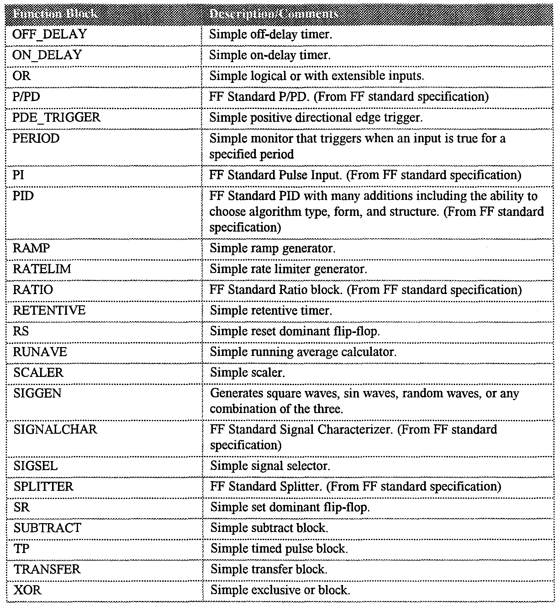


Claims
Priority Applications (4)
| Application Number | Priority Date | Filing Date | Title |
|---|---|---|---|
| JP53576498A JP2001512599A (en) | 1997-02-14 | 1998-02-06 | Process control system using hierarchical hierarchical control strategy distributed among multiple controllers |
| AU62521/98A AU6252198A (en) | 1997-02-14 | 1998-02-06 | Process control system using a layered-hierarchy control strategy distributed into multiple control devices |
| DE19882117T DE19882117T1 (en) | 1997-02-14 | 1998-02-06 | Process control system using a multi-tier hierarchy control strategy distributed in a variety of control devices |
| GB9918413A GB2336977B (en) | 1997-02-14 | 1998-02-06 | Process control system using a layered-hierarchy control strategy distributed into multiple control devices |
Applications Claiming Priority (2)
| Application Number | Priority Date | Filing Date | Title |
|---|---|---|---|
| US08/799,966 | 1997-02-14 | ||
| US08/799,966 US5980078A (en) | 1997-02-14 | 1997-02-14 | Process control system including automatic sensing and automatic configuration of devices |
Publications (3)
| Publication Number | Publication Date |
|---|---|
| WO1998036335A2 true WO1998036335A2 (en) | 1998-08-20 |
| WO1998036335A3 WO1998036335A3 (en) | 1999-01-14 |
| WO1998036335A9 WO1998036335A9 (en) | 1999-02-18 |
Family
ID=25177183
Family Applications (3)
| Application Number | Title | Priority Date | Filing Date |
|---|---|---|---|
| PCT/US1998/001573 WO1998036335A2 (en) | 1997-02-14 | 1998-02-06 | Process control system using a layered-hierarchy control strategy distributed into multiple control devices |
| PCT/US1998/001570 WO1998036353A1 (en) | 1997-02-14 | 1998-02-06 | System for configuring a process control environment with graphical elements |
| PCT/US1998/001571 WO1998036336A1 (en) | 1997-02-14 | 1998-02-06 | System for assisting configuring a process control environment |
Family Applications After (2)
| Application Number | Title | Priority Date | Filing Date |
|---|---|---|---|
| PCT/US1998/001570 WO1998036353A1 (en) | 1997-02-14 | 1998-02-06 | System for configuring a process control environment with graphical elements |
| PCT/US1998/001571 WO1998036336A1 (en) | 1997-02-14 | 1998-02-06 | System for assisting configuring a process control environment |
Country Status (6)
| Country | Link |
|---|---|
| US (2) | US5980078A (en) |
| JP (8) | JP2001512598A (en) |
| AU (3) | AU6252198A (en) |
| DE (3) | DE19882113T1 (en) |
| GB (3) | GB2336446B (en) |
| WO (3) | WO1998036335A2 (en) |
Cited By (45)
| Publication number | Priority date | Publication date | Assignee | Title |
|---|---|---|---|---|
| GB2334596A (en) * | 1998-02-23 | 1999-08-25 | Denno Co Ltd | Modular, hierarchical control system |
| WO2000069116A2 (en) * | 1999-05-10 | 2000-11-16 | Siemens Aktiengesellschaft | Network comprising a number of nodes and nodes for such a network |
| WO2000075738A1 (en) * | 1999-06-09 | 2000-12-14 | Panja, Inc. | System and method of device interface configuration for a control system |
| WO2001029632A2 (en) * | 1999-10-18 | 2001-04-26 | Rosemount Inc. | Improved interface for managing test definitions |
| GB2358559A (en) * | 1999-10-04 | 2001-07-25 | Fisher Rosemount Systems Inc | Process control configuration system for use with a Profibus system |
| WO2002003634A1 (en) * | 2000-07-05 | 2002-01-10 | Telefonaktiebolaget Lm Ericsson (Publ) | Resource saving device and coupling of a connection in a telecommunication system |
| JP2002152994A (en) * | 2000-09-21 | 2002-05-24 | Abb Power Automation Ag | Method of forming control system for electrical switch assembly |
| EP1227378A2 (en) * | 2001-01-16 | 2002-07-31 | Siemens Aktiengesellschaft | Process for operating an automatisation system |
| EP1248171A2 (en) * | 2001-04-03 | 2002-10-09 | Siemens Aktiengesellschaft | Method and implementation of process control |
| JP2002297465A (en) * | 2001-03-30 | 2002-10-11 | Canon Inc | Apparatus for information processing, method for device setting and recording medium |
| WO2003001366A1 (en) | 2001-06-22 | 2003-01-03 | Wonderware Corporation | Supervisory process control and manufacturing information system application having a layered architecture |
| FR2839794A1 (en) * | 2002-05-20 | 2003-11-21 | Ge Med Sys Global Tech Co Llc | TEXT-BASED GENERIC SCRIPT PROCESSING FOR DYNAMIC CONFIGURATION OF DISTRIBUTED SYSTEMS |
| EP1410228A2 (en) * | 2001-06-22 | 2004-04-21 | Wonderware Corporation | Remotely monitoring / diagnosing distributed components of a supervisory process control and manufacturing information application from a central location |
| GB2394630A (en) * | 1999-10-04 | 2004-04-28 | Fisher Rosemount Systems Inc | Process control configuration system for use with a Profibus device network |
| US6738388B1 (en) | 1998-09-10 | 2004-05-18 | Fisher-Rosemount Systems, Inc. | Shadow function block interface for use in a process control network |
| GB2403043A (en) * | 2003-06-18 | 2004-12-22 | Fisher Rosemount Systems Inc | Configuration of a wireless enabled field device |
| US7139622B2 (en) | 2001-02-20 | 2006-11-21 | Pilz Gmbh & Co. | Method and device for programming a failsafe control system |
| EP1906288A2 (en) | 2006-09-29 | 2008-04-02 | Rockwell Automation Technologies, Inc. | Dynamic messages |
| US7463943B2 (en) | 2002-09-30 | 2008-12-09 | Koenig & Bauer Aktiengesellschaft | Method and devices for automatically supplying material to a processing machine |
| JP2011100469A (en) * | 2010-12-02 | 2011-05-19 | Canon Inc | Information processing apparatus, control method for the same, and program |
| EP2357541A1 (en) * | 2010-02-12 | 2011-08-17 | Rockwell Automation Technologies, Inc. | Macro function block for encapsulating device-level embedded logic |
| WO2011107332A1 (en) * | 2010-03-01 | 2011-09-09 | Rittal Gmbh & Co. Kg | Control cabinet monitoring device |
| CN102193536A (en) * | 2010-02-12 | 2011-09-21 | 洛克威尔自动控制技术股份有限公司 | Marco functional block for packaging device-level embedded logic |
| US8046271B2 (en) | 2002-12-23 | 2011-10-25 | Cybersource Corporation | Method and apparatus for custom strategy specification in a hosted electronic transaction service system |
| AU2006287639B2 (en) * | 2005-09-07 | 2011-12-22 | Open Invention Network, Llc | Method and computer program for device configuration |
| WO2012038265A1 (en) * | 2010-09-21 | 2012-03-29 | Airbus Operations Limited | Remote data concentrator |
| US8160574B1 (en) | 2005-06-17 | 2012-04-17 | Fisher-Rosemount Systems, Inc. | Wireless architecture utilizing geo-referencing |
| WO2012155985A1 (en) * | 2011-05-19 | 2012-11-22 | Siemens Aktiengesellschaft | Process visualisation in an automation system |
| CN102890453A (en) * | 2011-06-30 | 2013-01-23 | 通用电气公司 | Systems and methods for function block instantiation |
| US20130066443A1 (en) * | 2011-09-09 | 2013-03-14 | General Electric Company | Fieldbus device control system |
| CN103064751A (en) * | 2012-12-27 | 2013-04-24 | 中航(苏州)雷达与电子技术有限公司 | Method for removing recommend standard (RS) serial port interference of avionic devices |
| US8458659B2 (en) | 2001-06-22 | 2013-06-04 | Robert M. Resnick | Supervisory process control and manufacturing information system application having an extensible component model |
| US8464227B2 (en) | 2001-06-22 | 2013-06-11 | Invensys Systems, Inc. | Process control script development and execution facility supporting multiple user-side programming languages |
| EP1906276B1 (en) | 2006-09-29 | 2015-05-27 | Rockwell Automation Technologies, Inc. | HMI views of modules for industrial control systems |
| CN105511434A (en) * | 2015-12-16 | 2016-04-20 | 浙江中烟工业有限责任公司 | Production platform monitoring system with alarm function |
| DE10049503B4 (en) * | 1999-10-18 | 2017-07-27 | Fisher-Rosemount Systems, Inc. | Accessing and updating a configuration database of distributed physical locations within a process control system |
| RU180923U1 (en) * | 2017-11-24 | 2018-06-29 | Акционерное Общество "Приборный Завод "Тензор" (Ао "Тензор") | DISCRETE SIGNAL INPUT MODULE |
| RU180915U1 (en) * | 2017-12-14 | 2018-06-29 | Акционерное Общество "Приборный Завод "Тензор" (Ао "Тензор") | CPU MODULE |
| RU193222U1 (en) * | 2017-11-24 | 2019-10-17 | Акционерное Общество "Приборный Завод "Тензор" (Ао "Тензор") | MODULE OF CONTROL AND MANAGEMENT OF TECHNOLOGICAL PROCESSES |
| CN112505246A (en) * | 2020-11-11 | 2021-03-16 | 山西科致成科技有限公司 | Digital mining gas sensor calibration and verification device and method |
| NL2025804B1 (en) * | 2019-12-24 | 2021-09-02 | Nat Institute Of Intelligent Robotics Shenyang Co Ltd | Realization Method of 4diac-Based Distributed Multi-Axis Motion Control System Technical Field |
| WO2021202145A1 (en) * | 2020-04-01 | 2021-10-07 | Honeywell International Inc. | Optimal method of processing batch manufacturing events with linear computational complexity |
| GB2600822A (en) * | 2020-10-22 | 2022-05-11 | Fisher Rosemount Systems Inc | Industrial process control system as a data center of an industrial process plant |
| US11899410B1 (en) | 2022-12-15 | 2024-02-13 | Halliburton Energy Services, Inc. | Monitoring a wellbore operation using distributed artificial intelligence |
| US11899438B1 (en) | 2022-12-15 | 2024-02-13 | Halliburton Energy Services, Inc. | Distributed control system with failover capabilities for physical well equipment |
Families Citing this family (326)
| Publication number | Priority date | Publication date | Assignee | Title |
|---|---|---|---|---|
| US6205497B1 (en) * | 1994-09-07 | 2001-03-20 | Hewlett-Packard Company | System for configuring and input/output board in a computer |
| EP0825506B1 (en) | 1996-08-20 | 2013-03-06 | Invensys Systems, Inc. | Methods and apparatus for remote process control |
| US6424872B1 (en) | 1996-08-23 | 2002-07-23 | Fieldbus Foundation | Block oriented control system |
| US7146230B2 (en) * | 1996-08-23 | 2006-12-05 | Fieldbus Foundation | Integrated fieldbus data server architecture |
| US20040194101A1 (en) * | 1997-08-21 | 2004-09-30 | Glanzer David A. | Flexible function blocks |
| JP2950262B2 (en) * | 1996-11-29 | 1999-09-20 | 日本電気株式会社 | How to set up a multi-integrated agent system |
| AU6143398A (en) | 1997-02-07 | 1998-09-09 | Peter G. Brown | System and method for simulation and modeling of biopharmaceutical batch processmanufacturing facilities |
| US6662061B1 (en) | 1997-02-07 | 2003-12-09 | Peter G. Brown | System and method for simulation and modeling of batch process manufacturing facilities using process time lines |
| TW360829B (en) * | 1997-02-10 | 1999-06-11 | Siemens Ag | Auditory active communication-subscriber, communication-method and communication system with auditory active communication-subscriber |
| US5980078A (en) * | 1997-02-14 | 1999-11-09 | Fisher-Rosemount Systems, Inc. | Process control system including automatic sensing and automatic configuration of devices |
| US6983229B2 (en) * | 1997-06-20 | 2006-01-03 | Brown Peter G | Method for scheduling solution preparation in biopharmaceutical batch process manufacturing |
| US7043414B2 (en) * | 1997-06-20 | 2006-05-09 | Brown Peter G | System and method for simulating, modeling and scheduling of solution preparation in batch process manufacturing facilities |
| US6311093B1 (en) | 1997-06-20 | 2001-10-30 | Peter G. Brown | System and method for simulation, modeling and scheduling of equipment maintenance and calibration in biopharmaceutical batch process manufacturing facilities |
| US6999824B2 (en) | 1997-08-21 | 2006-02-14 | Fieldbus Foundation | System and method for implementing safety instrumented systems in a fieldbus architecture |
| ATE434315T1 (en) * | 1997-12-15 | 2009-07-15 | Thomson Licensing | ARCHITECTURE FOR A POWER LINE COMMUNICATION PROTOCOL |
| US6175770B1 (en) * | 1997-12-31 | 2001-01-16 | Dana Corporation | Electronic controller having automatic self-configuration capabilities |
| SE520101C2 (en) * | 1998-05-13 | 2003-05-27 | Axis Ab | Integrated circuit and method to induce an integrated circuit to execute instructions |
| US6542928B1 (en) * | 1998-06-02 | 2003-04-01 | Micron Technology, Inc. | Automatic configuration of testers and hosts on a computer network |
| US6219700B1 (en) * | 1998-07-28 | 2001-04-17 | Sun Microsystems, Inc. | Method and apparatus for managing services in a computer network from a central console |
| JP3293779B2 (en) | 1998-08-25 | 2002-06-17 | キヤノン株式会社 | Signal processing device and control method thereof |
| US6430610B1 (en) * | 1998-09-02 | 2002-08-06 | Steeleye Technology, Inc. | TCP/IP address protection mechanism in a clustered server environment |
| US6198480B1 (en) * | 1998-10-07 | 2001-03-06 | Wonderware Corporation | Object-oriented tag browser |
| US7039688B2 (en) * | 1998-11-12 | 2006-05-02 | Ricoh Co., Ltd. | Method and apparatus for automatic network configuration |
| EP1022697B1 (en) * | 1999-01-22 | 2004-05-19 | Fuji Electric Co., Ltd. | Control apparatus for vending machine |
| EP1031898A3 (en) * | 1999-02-26 | 2007-11-07 | Matsushita Electric Industrial Co., Ltd. | Communication system with initialization apparatus and program storage medium |
| US6438433B1 (en) * | 1999-04-16 | 2002-08-20 | Ncr Corporation | Financial document processing system and method of operating a financial document processing system |
| US6754885B1 (en) | 1999-05-17 | 2004-06-22 | Invensys Systems, Inc. | Methods and apparatus for controlling object appearance in a process control configuration system |
| US7089530B1 (en) | 1999-05-17 | 2006-08-08 | Invensys Systems, Inc. | Process control configuration system with connection validation and configuration |
| AU5273100A (en) | 1999-05-17 | 2000-12-05 | Foxboro Company, The | Methods and apparatus for control configuration with versioning, security, composite blocks, edit selection, object swapping, formulaic values and other aspects |
| AU5274600A (en) * | 1999-06-01 | 2000-12-18 | Foxboro Company, The | Systems and methods for linking parameters for the configuration of control systems |
| US6788980B1 (en) | 1999-06-11 | 2004-09-07 | Invensys Systems, Inc. | Methods and apparatus for control using control devices that provide a virtual machine environment and that communicate via an IP network |
| US6515683B1 (en) * | 1999-06-22 | 2003-02-04 | Siemens Energy And Automation | Autoconfiguring graphic interface for controllers having dynamic database structures |
| US6728590B1 (en) | 1999-07-14 | 2004-04-27 | Nec Electronics, Inc. | Identifying wafer fabrication system impacts resulting from specified actions |
| US6766212B1 (en) * | 1999-07-14 | 2004-07-20 | Nec Electronics, Inc. | Identifying relationships among constituent parts of a wafer fabrication system |
| US6510352B1 (en) | 1999-07-29 | 2003-01-21 | The Foxboro Company | Methods and apparatus for object-based process control |
| AU6702500A (en) * | 1999-08-23 | 2001-03-19 | Pilz Gmbh And Co. | Method of configuring a safe station and a safe control system using the same |
| US6618745B2 (en) * | 1999-09-10 | 2003-09-09 | Fisher Rosemount Systems, Inc. | Linking device in a process control system that allows the formation of a control loop having function blocks in a controller and in field devices |
| US6446202B1 (en) * | 1999-10-04 | 2002-09-03 | Fisher-Rosemount Systems, Inc. | Process control configuration system for use with an AS-Interface device network |
| US6711629B1 (en) * | 1999-10-18 | 2004-03-23 | Fisher-Rosemount Systems, Inc. | Transparent support of remote I/O in a process control system |
| EP1096349A1 (en) * | 1999-11-01 | 2001-05-02 | Abb Research Ltd. | Configuration of a plant guidance sytem |
| ATE287101T1 (en) * | 1999-11-01 | 2005-01-15 | Abb Research Ltd | INTEGRATION OF A FIELD CONTROL DEVICE INTO A PLANT CONTROL SYSTEM |
| US6473660B1 (en) | 1999-12-03 | 2002-10-29 | The Foxboro Company | Process control system and method with automatic fault avoidance |
| US6445678B1 (en) * | 1999-12-07 | 2002-09-03 | Intel Corporation | Method and apparatus for implementing leaf node proxy in a network |
| US7474929B2 (en) | 2000-01-20 | 2009-01-06 | Fisher-Rosemount Systems, Inc. | Enhanced tool for managing a process control network |
| US6772017B1 (en) * | 2000-01-20 | 2004-08-03 | Fisher-Rosemount Systems, Inc. | Tool for configuring and managing a process control network including the use of spatial information |
| US6779179B1 (en) | 2000-03-20 | 2004-08-17 | Exent Technologies, Inc. | Registry emulation |
| WO2001067379A2 (en) * | 2000-03-09 | 2001-09-13 | Exent Technologies, Inc. | Registry emulation |
| US20010049562A1 (en) * | 2000-03-10 | 2001-12-06 | Takuo Takano | Control system and control method |
| WO2001080410A1 (en) * | 2000-04-13 | 2001-10-25 | Infineon Technologies Ag | Voltage transformer |
| US6701357B1 (en) * | 2000-04-19 | 2004-03-02 | Toshiba America Information Systems, Inc. | Server appliance |
| JP2001319267A (en) * | 2000-05-09 | 2001-11-16 | Sanden Corp | Control system for automatic vending machine |
| US7228186B2 (en) | 2000-05-12 | 2007-06-05 | Rosemount Inc. | Field-mounted process device with programmable digital/analog interface |
| US7844365B2 (en) * | 2000-05-12 | 2010-11-30 | Rosemount Inc. | Field-mounted process device |
| US6574515B1 (en) | 2000-05-12 | 2003-06-03 | Rosemount Inc. | Two-wire field-mounted process device |
| US6611863B1 (en) | 2000-06-05 | 2003-08-26 | Intel Corporation | Automatic device assignment through programmable device discovery for policy based network management |
| US20050240286A1 (en) * | 2000-06-21 | 2005-10-27 | Glanzer David A | Block-oriented control system on high speed ethernet |
| US6947389B1 (en) * | 2000-06-30 | 2005-09-20 | Fisher-Rosemount Systems, Inc. | Two-mode foundation fieldbus device configurator |
| GB2395803B (en) * | 2000-06-30 | 2004-10-27 | Fisher Rosemount Systems Inc | Two-mode foundation fieldbus device configurator |
| US6473706B1 (en) | 2000-07-06 | 2002-10-29 | International Business Machines Corporation | Self-configuring and self-calibrating automated system |
| US6982953B1 (en) * | 2000-07-11 | 2006-01-03 | Scorpion Controls, Inc. | Automatic determination of correct IP address for network-connected devices |
| DE10040438A1 (en) * | 2000-08-18 | 2002-03-07 | Siemens Ag | Address assignment procedure for at least one new bus device connected to a bus system |
| US6944681B1 (en) * | 2000-09-08 | 2005-09-13 | Fisher-Rosemount Systems, Inc. | Probing algorithm for foundation fieldbus protocol |
| US20020184348A1 (en) * | 2000-09-20 | 2002-12-05 | Lockheed Martin Corporation | Object oriented framework architecture for sensing and/or control environments |
| US20020059467A1 (en) * | 2000-09-20 | 2002-05-16 | Lockheed Martin Corporation | Object oriented framework architecture for sensing and/or control environments |
| US6446160B1 (en) | 2000-09-28 | 2002-09-03 | International Business Machines Corporation | Multi-drive data storage system with analysis and selected demounting of idle data storage media |
| US6604160B1 (en) | 2000-09-28 | 2003-08-05 | International Business Machines Corporation | Computing system arbitrating and selectively providing resource-seeking tasks with takeaway of non-shareable resources |
| US6434682B1 (en) | 2000-09-28 | 2002-08-13 | International Business Machines Corporation | Data management system with shortcut migration via efficient automatic reconnection to previously migrated copy |
| CA2429480A1 (en) * | 2000-11-22 | 2002-05-30 | Tomiya Mano | Ophthalmological preparations |
| EP1211582B1 (en) * | 2000-11-30 | 2003-05-21 | Siemens Building Technologies AG | Arrangement for the surveillance, control and regulation of a technical installation of a building automation system |
| US8219662B2 (en) | 2000-12-06 | 2012-07-10 | International Business Machines Corporation | Redirecting data generated by network devices |
| US7054946B2 (en) * | 2000-12-06 | 2006-05-30 | Intelliden | Dynamic configuration of network devices to enable data transfers |
| US6978301B2 (en) * | 2000-12-06 | 2005-12-20 | Intelliden | System and method for configuring a network device |
| US7249170B2 (en) | 2000-12-06 | 2007-07-24 | Intelliden | System and method for configuration, management and monitoring of network resources |
| US20020069271A1 (en) * | 2000-12-06 | 2002-06-06 | Glen Tindal | Event manager for network operating system |
| EP1342342B1 (en) * | 2000-12-14 | 2008-07-30 | Hirschmann Electronics GmbH & Co. KG | Automatic configuration of a network |
| US6917857B2 (en) * | 2000-12-15 | 2005-07-12 | American Standard International Inc. | Magnetically overridden flow control device |
| US6674533B2 (en) | 2000-12-21 | 2004-01-06 | Joseph K. Price | Anodizing system with a coating thickness monitor and an anodized product |
| US7274463B2 (en) * | 2003-12-30 | 2007-09-25 | Sensory Analytics | Anodizing system with a coating thickness monitor and an anodized product |
| US7365860B2 (en) * | 2000-12-21 | 2008-04-29 | Sensory Analytics | System capable of determining applied and anodized coating thickness of a coated-anodized product |
| IT1319716B1 (en) * | 2000-12-28 | 2003-11-03 | Abb Ricerca Spa | COMPUTERIZED SYSTEM TO PERFORM REMOTE EDIAGNOSTIC CONFIGURATION OPERATIONS ON A FIELD DEVICE |
| US7185083B2 (en) * | 2001-01-17 | 2007-02-27 | Fisher-Rosemount Systems, Inc. | Method and apparatus for identifying an I/O network in a process control system |
| FR2820222B1 (en) * | 2001-01-26 | 2003-03-21 | Schneider Automation | METHOD FOR PROGRAMMING AN AUTOMATION APPLICATION |
| EP1233318A1 (en) * | 2001-02-16 | 2002-08-21 | Abb Research Ltd. | Software coumpounds for a distributed control system |
| US7150037B2 (en) * | 2001-03-21 | 2006-12-12 | Intelliden, Inc. | Network configuration manager |
| US6687733B2 (en) * | 2001-06-01 | 2004-02-03 | Intergenix | Method and system for automatically configuring a client-server network |
| US8001594B2 (en) * | 2001-07-30 | 2011-08-16 | Ipass, Inc. | Monitoring computer network security enforcement |
| US6819960B1 (en) | 2001-08-13 | 2004-11-16 | Rockwell Software Inc. | Industrial controller automation interface |
| DE10140763A1 (en) * | 2001-08-20 | 2003-03-06 | Siemens Ag | Method and arrangement for the configuration of assemblies in a data processing system |
| US7200548B2 (en) * | 2001-08-29 | 2007-04-03 | Intelliden | System and method for modeling a network device's configuration |
| US8296400B2 (en) | 2001-08-29 | 2012-10-23 | International Business Machines Corporation | System and method for generating a configuration schema |
| JP3693337B2 (en) * | 2001-09-10 | 2005-09-07 | デンセイ・ラムダ株式会社 | Power system wiring diagram creation system, and power supply equipment and program used therefor |
| CA2357444A1 (en) * | 2001-09-13 | 2003-03-13 | Armadillo Networks Inc. | System and methods for automatic negotiation in distributed computing |
| FR2830152B1 (en) * | 2001-09-27 | 2004-08-20 | Airbus France | DETERMINIST FIELD BUS AND METHOD FOR MANAGING SUCH A BUS |
| DE10149147A1 (en) * | 2001-10-04 | 2003-04-17 | Heidenhain Gmbh Dr Johannes | Method and device for creating or changing NC programs |
| US20030079053A1 (en) * | 2001-10-23 | 2003-04-24 | Kevin Burns | System and method for evaluating effectiveness of network configuration management tools |
| US6567272B1 (en) * | 2001-11-09 | 2003-05-20 | Dell Products L.P. | System and method for utilizing system configurations in a modular computer system |
| KR100423969B1 (en) * | 2001-11-16 | 2004-03-22 | 삼성전자주식회사 | Field bus interface board and control method thereof |
| US7065562B2 (en) * | 2001-11-26 | 2006-06-20 | Intelliden, Inc. | System and method for generating a representation of a configuration schema |
| US7139839B2 (en) * | 2001-11-26 | 2006-11-21 | Schneider Automation Inc. | Method and apparatus for assigning a network node address |
| EP1489476B1 (en) * | 2001-12-06 | 2019-12-04 | Fisher-Rosemount Systems, Inc. | Intrinsically safe field maintenance tool |
| US7426452B2 (en) | 2001-12-06 | 2008-09-16 | Fisher-Rosemount Systems. Inc. | Dual protocol handheld field maintenance tool with radio-frequency communication |
| US20030204373A1 (en) * | 2001-12-06 | 2003-10-30 | Fisher-Rosemount Systems, Inc. | Wireless communication method between handheld field maintenance tools |
| US20030229472A1 (en) * | 2001-12-06 | 2003-12-11 | Kantzes Christopher P. | Field maintenance tool with improved device description communication and storage |
| EP1454202B1 (en) * | 2001-12-06 | 2005-11-02 | Fisher-Rosemount Systems, Inc. | Intrinsically safe field maintenance tool |
| JP4234342B2 (en) * | 2001-12-26 | 2009-03-04 | パナソニック株式会社 | Component mounting operation support system and method for component mounting apparatus |
| US7080093B2 (en) * | 2002-01-14 | 2006-07-18 | Sun Microsystems, Inc. | System and method for database design |
| US6973508B2 (en) * | 2002-02-12 | 2005-12-06 | Fisher-Rosemount Systems, Inc. | Highly versatile process control system controller |
| JP4150524B2 (en) | 2002-02-13 | 2008-09-17 | 株式会社リコー | Production management method and production management program |
| DE10207831A1 (en) * | 2002-02-25 | 2003-09-04 | Siemens Ag | Procedure for configuring and / or configuring a project |
| US7519729B2 (en) * | 2002-02-27 | 2009-04-14 | Ricoh Co. Ltd. | Method and apparatus for monitoring remote devices through a local monitoring station and communicating with a central station supporting multiple manufacturers |
| US7027952B2 (en) * | 2002-03-12 | 2006-04-11 | Fisher-Rosemount Systems, Inc. | Data transmission method for a multi-protocol handheld field maintenance tool |
| US7039744B2 (en) * | 2002-03-12 | 2006-05-02 | Fisher-Rosemount Systems, Inc. | Movable lead access member for handheld field maintenance tool |
| US20030174068A1 (en) * | 2002-03-15 | 2003-09-18 | Dobos Jeffrey A. | Apparatus for calibrating a digital field sensor |
| DE10212131A1 (en) * | 2002-03-19 | 2003-10-02 | Siemens Ag | Process for monitoring an automation system |
| KR20030075728A (en) * | 2002-03-20 | 2003-09-26 | 엘지전자 주식회사 | Method for confirming a home appliance connect state of home network system |
| US7565456B2 (en) * | 2002-04-12 | 2009-07-21 | Siemens Aktiengesellschaft | Method for reconfiguring an automation device |
| AU2003234106A1 (en) | 2002-04-15 | 2003-11-03 | Invensys Systems, Inc. | Methods and apparatus for process, factory-floor, environmental, computer aided manufacturing-based or other control system with real-time data distribution |
| US20030195952A1 (en) * | 2002-04-15 | 2003-10-16 | Henry Steven G. | Digital transmitter device configuration |
| US6907305B2 (en) * | 2002-04-30 | 2005-06-14 | Advanced Micro Devices, Inc. | Agent reactive scheduling in an automated manufacturing environment |
| US6959329B2 (en) * | 2002-05-15 | 2005-10-25 | Intelliden | System and method for transforming configuration commands |
| JP2003339729A (en) | 2002-05-22 | 2003-12-02 | Olympus Optical Co Ltd | Ultrasonic operation apparatus |
| US20030222903A1 (en) * | 2002-05-31 | 2003-12-04 | Wolfgang Herzog | Distributing customized computer settings to affected systems |
| US20040003067A1 (en) * | 2002-06-27 | 2004-01-01 | Daniel Ferrin | System and method for enabling a user interface with GUI meta data |
| CN100375086C (en) * | 2002-07-03 | 2008-03-12 | 东京电子株式会社 | Method and device for dynamic sensor configuration and runtime execution |
| US7464145B2 (en) | 2002-07-11 | 2008-12-09 | Intelliden, Inc. | Repository-independent system and method for asset management and reconciliation |
| US7366893B2 (en) * | 2002-08-07 | 2008-04-29 | Intelliden, Inc. | Method and apparatus for protecting a network from attack |
| US7461158B2 (en) | 2002-08-07 | 2008-12-02 | Intelliden, Inc. | System and method for controlling access rights to network resources |
| US7558847B2 (en) * | 2002-09-13 | 2009-07-07 | Intelliden, Inc. | System and method for mapping between and controlling different device abstractions |
| DE10246895B3 (en) * | 2002-10-08 | 2004-06-09 | Siemens Ag | Procedure for changing a parameter for the operation of a network and participants for performing the procedure |
| DE10348563B4 (en) * | 2002-10-22 | 2014-01-09 | Fisher-Rosemount Systems, Inc. | Integration of graphic display elements, process modules and control modules in process plants |
| US9983559B2 (en) | 2002-10-22 | 2018-05-29 | Fisher-Rosemount Systems, Inc. | Updating and utilizing dynamic process simulation in an operating process environment |
| US7146231B2 (en) | 2002-10-22 | 2006-12-05 | Fisher-Rosemount Systems, Inc.. | Smart process modules and objects in process plants |
| US10261506B2 (en) | 2002-12-05 | 2019-04-16 | Fisher-Rosemount Systems, Inc. | Method of adding software to a field maintenance tool |
| CN100388529C (en) | 2003-03-06 | 2008-05-14 | 费希尔-罗斯蒙德系统公司 | Heat flow regulating cover for an electrical storage cell |
| US7970006B1 (en) * | 2003-03-10 | 2011-06-28 | Ciena Corporation | Dynamic configuration for a modular interconnect |
| US7366651B1 (en) * | 2003-03-14 | 2008-04-29 | Xilinx, Inc. | Co-simulation interface |
| JP3963174B2 (en) * | 2003-03-14 | 2007-08-22 | オムロン株式会社 | Display / editing apparatus, display method, and program |
| AU2004231988B2 (en) | 2003-04-16 | 2010-04-15 | Drexel University | Acoustic blood analyzer for assessing blood properties |
| US7512521B2 (en) | 2003-04-30 | 2009-03-31 | Fisher-Rosemount Systems, Inc. | Intrinsically safe field maintenance tool with power islands |
| US7054695B2 (en) | 2003-05-15 | 2006-05-30 | Fisher-Rosemount Systems, Inc. | Field maintenance tool with enhanced scripts |
| US7036386B2 (en) * | 2003-05-16 | 2006-05-02 | Fisher-Rosemount Systems, Inc. | Multipurpose utility mounting assembly for handheld field maintenance tool |
| US7199784B2 (en) * | 2003-05-16 | 2007-04-03 | Fisher Rosemount Systems, Inc. | One-handed operation of a handheld field maintenance tool |
| US8874402B2 (en) | 2003-05-16 | 2014-10-28 | Fisher-Rosemount Systems, Inc. | Physical memory handling for handheld field maintenance tools |
| US6925419B2 (en) | 2003-05-16 | 2005-08-02 | Fisher-Rosemount Systems, Inc. | Intrinsically safe field maintenance tool with removable battery pack |
| US7526802B2 (en) | 2003-05-16 | 2009-04-28 | Fisher-Rosemount Systems, Inc. | Memory authentication for intrinsically safe field maintenance tools |
| US7197580B2 (en) * | 2003-05-29 | 2007-03-27 | Microsoft Corporation | Computer system and method for supporting network-enabled devices |
| WO2004107067A1 (en) * | 2003-06-02 | 2004-12-09 | Abb Research Ltd | A method and a tool for allocating computational resources in a distributed control system |
| JP2005025652A (en) * | 2003-07-01 | 2005-01-27 | System V:Kk | Information conversion device for device management |
| DE10343670A1 (en) * | 2003-09-18 | 2005-05-25 | Endress + Hauser Conducta Gesellschaft für Mess- und Regeltechnik mbH + Co. KG | Device driver for field devices of process automation technology |
| US7865907B2 (en) * | 2003-09-25 | 2011-01-04 | Fisher-Rosemount Systems, Inc. | Method and apparatus for providing automatic software updates |
| US7016741B2 (en) * | 2003-10-14 | 2006-03-21 | Rosemount Inc. | Process control loop signal converter |
| US20050092253A1 (en) * | 2003-11-04 | 2005-05-05 | Venkat Selvamanickam | Tape-manufacturing system having extended operational capabilites |
| CN100445905C (en) * | 2003-12-04 | 2008-12-24 | 霍尼韦尔国际公司 | System and method for the safe automatic detection of a field device communicating with current modulated signal |
| US7257498B2 (en) * | 2003-12-04 | 2007-08-14 | Honeywell International Inc. | System and method for the safe automatic detection of a field device communicating with current modulated signal |
| DE602004016210D1 (en) * | 2003-12-04 | 2008-10-09 | Honeywell Int Inc | SYSTEM AND METHOD FOR THE SAFE AUTOMATIC DETECTION OF A FIELD DEVICE COMMUNICATING WITH A CURRENT MODULATED SIGNAL |
| DE10357276B4 (en) * | 2003-12-05 | 2012-02-23 | Abb Research Ltd. | System and method for the directed provision and installation of device-specific functionalities and / or information for the field devices of a distributed system |
| US7146034B2 (en) | 2003-12-09 | 2006-12-05 | Superpower, Inc. | Tape manufacturing system |
| US7359317B1 (en) * | 2004-02-20 | 2008-04-15 | Excel Switching Corporation | Redundancy arrangement for telecommunications switch |
| US7761923B2 (en) | 2004-03-01 | 2010-07-20 | Invensys Systems, Inc. | Process control methods and apparatus for intrusion detection, protection and network hardening |
| US20050223983A1 (en) * | 2004-04-08 | 2005-10-13 | Venkat Selvamanickam | Chemical vapor deposition (CVD) apparatus usable in the manufacture of superconducting conductors |
| US20050223984A1 (en) * | 2004-04-08 | 2005-10-13 | Hee-Gyoun Lee | Chemical vapor deposition (CVD) apparatus usable in the manufacture of superconducting conductors |
| JP4381872B2 (en) * | 2004-04-09 | 2009-12-09 | 矢崎総業株式会社 | Wire crimping method |
| JP2005327263A (en) * | 2004-04-13 | 2005-11-24 | Omron Corp | Control system setting device |
| US8463879B2 (en) * | 2004-04-19 | 2013-06-11 | Hewlett-Packard Development Company, L.P. | Method and apparatus for automatic verification of a machine-readable map of networked devices |
| US20050267964A1 (en) * | 2004-04-28 | 2005-12-01 | Guenter Kech | Method for providing apparatus specific information and corresponding system |
| DE102004021089A1 (en) * | 2004-04-29 | 2005-11-24 | Bosch Rexroth Ag | Device for address assignment in a standardized fieldbus system |
| JP2007536634A (en) | 2004-05-04 | 2007-12-13 | フィッシャー−ローズマウント・システムズ・インコーポレーテッド | Service-oriented architecture for process control systems |
| US7729789B2 (en) | 2004-05-04 | 2010-06-01 | Fisher-Rosemount Systems, Inc. | Process plant monitoring based on multivariate statistical analysis and on-line process simulation |
| US20050268012A1 (en) * | 2004-05-05 | 2005-12-01 | Ralf Schaetzle | Method for automatic configuration of a process control system and corresponding process control system |
| GB0415144D0 (en) * | 2004-07-06 | 2004-08-11 | Attar Software Ltd | Method and system for detecting events in process operating data and identifying associations between related events |
| US7735063B2 (en) * | 2004-07-07 | 2010-06-08 | Sap Aktiengesellschaft | Providing customizable configuration data in computer systems |
| US7774369B2 (en) | 2004-07-07 | 2010-08-10 | Sap Aktiengesellschaft | Configuring computer systems with business configuration information |
| US7904488B2 (en) | 2004-07-21 | 2011-03-08 | Rockwell Automation Technologies, Inc. | Time stamp methods for unified plant model |
| DE102004037064A1 (en) * | 2004-07-30 | 2006-02-16 | Abb Patent Gmbh | Method and device for functional testing of a field device before its initial commissioning |
| DE102004040282A1 (en) * | 2004-08-19 | 2006-03-09 | Siemens Ag | Parameter identification for field devices in automation technology |
| US7387811B2 (en) * | 2004-09-21 | 2008-06-17 | Superpower, Inc. | Method for manufacturing high temperature superconducting conductors using chemical vapor deposition (CVD) |
| US7937549B2 (en) * | 2004-09-21 | 2011-05-03 | International Business Machines Corporation | Storage system and subsystem to automatically detect hardware configuration changes |
| US8756521B1 (en) | 2004-09-30 | 2014-06-17 | Rockwell Automation Technologies, Inc. | Systems and methods for automatic visualization configuration |
| WO2006099540A2 (en) | 2005-03-15 | 2006-09-21 | Trapeze Networks, Inc. | System and method for distributing keys in a wireless network |
| DE102005019970B4 (en) * | 2005-04-27 | 2007-04-26 | Phoenix Contact Gmbh & Co. Kg | Address assignment for secure bus users |
| US7676281B2 (en) | 2005-05-13 | 2010-03-09 | Rockwell Automation Technologies, Inc. | Distributed database in an industrial automation environment |
| US8799800B2 (en) | 2005-05-13 | 2014-08-05 | Rockwell Automation Technologies, Inc. | Automatic user interface generation |
| US7650405B2 (en) | 2005-05-13 | 2010-01-19 | Rockwell Automation Technologies, Inc. | Tracking and tracing across process boundaries in an industrial automation environment |
| US7672737B2 (en) | 2005-05-13 | 2010-03-02 | Rockwell Automation Technologies, Inc. | Hierarchically structured data model for utilization in industrial automation environments |
| US7809683B2 (en) | 2005-05-13 | 2010-10-05 | Rockwell Automation Technologies, Inc. | Library that includes modifiable industrial automation objects |
| US8332560B2 (en) * | 2005-07-11 | 2012-12-11 | Dell Products L.P. | System and method for identifying inoperable connection points in a storage enclosure |
| US7835295B2 (en) * | 2005-07-19 | 2010-11-16 | Rosemount Inc. | Interface module with power over Ethernet function |
| WO2007012074A1 (en) * | 2005-07-20 | 2007-01-25 | Rosemount Inc. | Field device with power over ethernet |
| DE102005034944B3 (en) * | 2005-07-22 | 2006-11-09 | Siemens Ag | Field bus system e.g. LIN bus system, configuration method for use in e.g. motor vehicle, involves checking whether bus subscriber still has standard address, and identifying subscriber and assigning clear subscriber address to subscriber |
| US7421526B2 (en) * | 2005-08-24 | 2008-09-02 | Honeywell International Inc. | Reconfigurable virtual backplane architecture |
| US7609713B2 (en) * | 2005-09-29 | 2009-10-27 | Fisher-Rosemount Systems, Inc. | Associating a signal measurement with a communication device on a network |
| US8132240B2 (en) * | 2005-09-29 | 2012-03-06 | Siemens Aktiengesellschaft | Electric field unit and method for executing a protected function of an electric field unit |
| US7881812B2 (en) | 2005-09-29 | 2011-02-01 | Rockwell Automation Technologies, Inc. | Editing and configuring device |
| US7548789B2 (en) | 2005-09-29 | 2009-06-16 | Rockwell Automation Technologies, Inc. | Editing lifecycle and deployment of objects in an industrial automation environment |
| US7801628B2 (en) | 2005-09-30 | 2010-09-21 | Rockwell Automation Technologies, Inc. | Industrial operator interfaces interacting with higher-level business workflow |
| US7660638B2 (en) | 2005-09-30 | 2010-02-09 | Rockwell Automation Technologies, Inc. | Business process execution engine |
| US7734590B2 (en) | 2005-09-30 | 2010-06-08 | Rockwell Automation Technologies, Inc. | Incremental association of metadata to production data |
| US8275680B2 (en) | 2005-09-30 | 2012-09-25 | Rockwell Automation Technologies, Inc. | Enabling transactional mechanisms in an automated controller system |
| US7526794B2 (en) | 2005-09-30 | 2009-04-28 | Rockwell Automation Technologies, Inc. | Data perspectives in controller system and production management systems |
| US8484250B2 (en) | 2005-09-30 | 2013-07-09 | Rockwell Automation Technologies, Inc. | Data federation with industrial control systems |
| US8527888B2 (en) * | 2006-04-11 | 2013-09-03 | Invensys Systems, Inc. | Method and supporting configuration user interfaces for streamlining installing replacement field devices |
| US8638762B2 (en) | 2005-10-13 | 2014-01-28 | Trapeze Networks, Inc. | System and method for network integrity |
| WO2007044986A2 (en) | 2005-10-13 | 2007-04-19 | Trapeze Networks, Inc. | System and method for remote monitoring in a wireless network |
| US7573859B2 (en) | 2005-10-13 | 2009-08-11 | Trapeze Networks, Inc. | System and method for remote monitoring in a wireless network |
| US7724703B2 (en) | 2005-10-13 | 2010-05-25 | Belden, Inc. | System and method for wireless network monitoring |
| US8250587B2 (en) | 2005-10-27 | 2012-08-21 | Trapeze Networks, Inc. | Non-persistent and persistent information setting method and system for inter-process communication |
| US20070106778A1 (en) * | 2005-10-27 | 2007-05-10 | Zeldin Paul E | Information and status and statistics messaging method and system for inter-process communication |
| EP1969429A2 (en) | 2005-12-05 | 2008-09-17 | Fisher-Rosemount Systems, Inc. | Multi-objective predictive process optimization with concurrent process simulation |
| US8676357B2 (en) | 2005-12-20 | 2014-03-18 | Fieldbus Foundation | System and method for implementing an extended safety instrumented system |
| US7489977B2 (en) * | 2005-12-20 | 2009-02-10 | Fieldbus Foundation | System and method for implementing time synchronization monitoring and detection in a safety instrumented system |
| DE102007003196A1 (en) * | 2006-01-23 | 2007-07-26 | Abb Patent Gmbh | communication system |
| WO2007103304A2 (en) * | 2006-03-07 | 2007-09-13 | Sensory Analytics | A mobile apparatus capable of surface measurements of a coating thickness |
| WO2007123753A2 (en) | 2006-03-30 | 2007-11-01 | Invensys Systems, Inc. | Digital data processing apparatus and methods for improving plant performance |
| US7558266B2 (en) | 2006-05-03 | 2009-07-07 | Trapeze Networks, Inc. | System and method for restricting network access using forwarding databases |
| US8966018B2 (en) | 2006-05-19 | 2015-02-24 | Trapeze Networks, Inc. | Automated network device configuration and network deployment |
| US20070268515A1 (en) * | 2006-05-19 | 2007-11-22 | Yun Freund | System and method for automatic configuration of remote network switch and connected access point devices |
| US7813817B2 (en) * | 2006-05-19 | 2010-10-12 | Westinghouse Electric Co Llc | Computerized procedures system |
| US9191799B2 (en) | 2006-06-09 | 2015-11-17 | Juniper Networks, Inc. | Sharing data between wireless switches system and method |
| US9258702B2 (en) | 2006-06-09 | 2016-02-09 | Trapeze Networks, Inc. | AP-local dynamic switching |
| US8818322B2 (en) | 2006-06-09 | 2014-08-26 | Trapeze Networks, Inc. | Untethered access point mesh system and method |
| US20080005344A1 (en) * | 2006-06-29 | 2008-01-03 | Ford Daniel E | Method and system for configuring a network device using a template |
| US8311650B2 (en) * | 2006-07-13 | 2012-11-13 | Mitsubishi Electric Corporation | Equipment management system, programmable controller and centralized controller |
| US7668608B2 (en) * | 2006-09-01 | 2010-02-23 | Fisher-Rosemount Systems, Inc. | Graphical programming language object editing and reporting tool |
| US7953713B2 (en) * | 2006-09-14 | 2011-05-31 | International Business Machines Corporation | System and method for representing and using tagged data in a management system |
| US8340110B2 (en) | 2006-09-15 | 2012-12-25 | Trapeze Networks, Inc. | Quality of service provisioning for wireless networks |
| US7873061B2 (en) | 2006-12-28 | 2011-01-18 | Trapeze Networks, Inc. | System and method for aggregation and queuing in a wireless network |
| US7684875B2 (en) * | 2007-02-02 | 2010-03-23 | Fisher-Rosemount Systems, Inc. | Methods and apparatus to configure process control system inputs and outputs |
| US7634322B2 (en) * | 2007-03-23 | 2009-12-15 | Honeywell International Inc. | Configuration of wireless field devices for process control plants |
| DE102007032810B3 (en) * | 2007-07-13 | 2008-11-27 | Siemens Ag | Method for allocation of physical position to slave module or for allocation of physical position to channel of slave module in decentralized, event-controlled bus system with serial data communication, involves selecting start-up mode |
| US8902904B2 (en) | 2007-09-07 | 2014-12-02 | Trapeze Networks, Inc. | Network assignment based on priority |
| DE102007043795A1 (en) * | 2007-09-13 | 2009-04-02 | Siemens Ag | Control system for a technical system and method for operating a process control system |
| KR20090034495A (en) * | 2007-10-04 | 2009-04-08 | 삼성전자주식회사 | Production management system and control method thereof |
| US8412922B2 (en) * | 2007-10-24 | 2013-04-02 | Sercomm Corporation | On-site configuration of a hardware device module of a security system |
| US9154379B2 (en) * | 2007-10-25 | 2015-10-06 | Sercomm Corporation | Remote configuration of a hardware device module of a security system |
| CN101150460A (en) * | 2007-11-14 | 2008-03-26 | 华为技术有限公司 | Method and system for automatic debugging and testing of network devices |
| US8238942B2 (en) | 2007-11-21 | 2012-08-07 | Trapeze Networks, Inc. | Wireless station location detection |
| DE102008010864A1 (en) * | 2008-02-25 | 2009-08-27 | Endress + Hauser Process Solutions Ag | Method for operating a field device |
| JP5092800B2 (en) * | 2008-03-03 | 2012-12-05 | 横河電機株式会社 | Field device management device |
| US8150357B2 (en) | 2008-03-28 | 2012-04-03 | Trapeze Networks, Inc. | Smoothing filter for irregular update intervals |
| EP2110725B1 (en) * | 2008-04-18 | 2012-10-31 | Siemens Aktiengesellschaft | System and method for allocating a device name |
| JP5030852B2 (en) * | 2008-04-26 | 2012-09-19 | 三菱電機株式会社 | Device management apparatus, device management method, and program |
| US8635313B2 (en) * | 2008-06-19 | 2014-01-21 | Microsoft Corporation | Network device installation |
| EP2304536A4 (en) | 2008-06-20 | 2012-08-15 | Invensys Sys Inc | Systems and methods for immersive interaction with actual and/or simulated facilities for process, environmental and industrial control |
| US8978105B2 (en) | 2008-07-25 | 2015-03-10 | Trapeze Networks, Inc. | Affirming network relationships and resource access via related networks |
| US8238298B2 (en) | 2008-08-29 | 2012-08-07 | Trapeze Networks, Inc. | Picking an optimal channel for an access point in a wireless network |
| US8825462B2 (en) * | 2008-09-17 | 2014-09-02 | Accenture Global Services Limited | Method and system for simulating a plurality of devices |
| US8229575B2 (en) | 2008-09-19 | 2012-07-24 | Rockwell Automation Technologies, Inc. | Automatically adjustable industrial control configuration |
| US8255497B2 (en) * | 2008-11-03 | 2012-08-28 | Lincoln Global, Inc. | Method of discovery and communication with industrial equipment |
| ATE513388T1 (en) * | 2008-11-12 | 2011-07-15 | Grieshaber Vega Kg | GENERATE A DEVICE DESCRIPTION FOR A MEASURING DEVICE |
| US10075558B2 (en) * | 2008-12-09 | 2018-09-11 | Philips Lighting Holding B.V. | System and method for automatically integrating a device in a networked system |
| US20100175012A1 (en) * | 2009-01-06 | 2010-07-08 | Allstrom Peter E | System and Method for Remote Monitoring and Control of Field Device |
| US8881039B2 (en) | 2009-03-13 | 2014-11-04 | Fisher-Rosemount Systems, Inc. | Scaling composite shapes for a graphical human-machine interface |
| EP2249217B1 (en) * | 2009-05-08 | 2013-04-24 | Siemens Aktiengesellschaft | Automation device and automation system |
| US8127060B2 (en) | 2009-05-29 | 2012-02-28 | Invensys Systems, Inc | Methods and apparatus for control configuration with control objects that are fieldbus protocol-aware |
| US8463964B2 (en) | 2009-05-29 | 2013-06-11 | Invensys Systems, Inc. | Methods and apparatus for control configuration with enhanced change-tracking |
| US20110004589A1 (en) * | 2009-07-06 | 2011-01-06 | Rockwell Automation Technologies, Inc. | Diagnostics in a distributed directory system |
| US8311778B2 (en) * | 2009-09-22 | 2012-11-13 | Rosemount Inc. | Industrial process control transmitter with multiple sensors |
| US8825183B2 (en) | 2010-03-22 | 2014-09-02 | Fisher-Rosemount Systems, Inc. | Methods for a data driven interface based on relationships between process control tags |
| US9392072B2 (en) | 2010-04-15 | 2016-07-12 | Rockwell Automation Technologies, Inc. | Systems and methods for conducting communications among components of multidomain industrial automation system |
| US8484401B2 (en) | 2010-04-15 | 2013-07-09 | Rockwell Automation Technologies, Inc. | Systems and methods for conducting communications among components of multidomain industrial automation system |
| US8984533B2 (en) | 2010-04-15 | 2015-03-17 | Rockwell Automation Technologies, Inc. | Systems and methods for conducting communications among components of multidomain industrial automation system |
| US8352641B2 (en) | 2010-04-21 | 2013-01-08 | General Electric Company | Systems and methods for identifying fieldbus devices in a control system |
| US20110265072A1 (en) * | 2010-04-27 | 2011-10-27 | Jack Matthew | Dynamic Installation of Files for Running Programs |
| US8745278B2 (en) | 2010-10-13 | 2014-06-03 | Rosemount Inc. | Field device with self description |
| JP5639909B2 (en) * | 2011-01-27 | 2014-12-10 | アズビル株式会社 | Drawing editor and drawing method |
| DE102011004802A1 (en) * | 2011-02-25 | 2012-08-30 | Interroll-Holding Ag | Method for setting up a conveying device |
| KR20120109665A (en) * | 2011-03-23 | 2012-10-08 | 삼성전자주식회사 | Method, apparatus and system for information push service based on wirless lan access point |
| US8983636B1 (en) * | 2011-10-28 | 2015-03-17 | Englobal Corporation | Client configuration tool |
| US8856415B2 (en) * | 2012-02-01 | 2014-10-07 | National Instruments Corporation | Bus arbitration for a real-time computer system |
| DE102012102187C5 (en) | 2012-03-15 | 2016-11-03 | Phoenix Contact Gmbh & Co. Kg | Control device for controlling safety-critical processes in an automated system and method for parameterizing the control device |
| US8745281B2 (en) * | 2012-04-23 | 2014-06-03 | General Electric Company | Automatic foundation fieldbus device commissioning |
| CN103558809B (en) * | 2012-05-09 | 2019-06-18 | 布里斯托尔D/B/A远程自动化解决方案公司 | The method and apparatus of configuration process control equipment |
| US20140025186A1 (en) * | 2012-07-19 | 2014-01-23 | General Electric Company | Systems and methods for device commissioning and decommissioning |
| US9052708B2 (en) * | 2012-09-05 | 2015-06-09 | General Electric Company | Systems and methods for improved device commissioning and decommissioning |
| JP6121706B2 (en) * | 2012-12-13 | 2017-04-26 | アズビル株式会社 | Programming method and apparatus |
| CN103092107A (en) * | 2012-12-26 | 2013-05-08 | 华东师范大学 | Portable digital experimental monitor terminal system |
| JP6263836B2 (en) * | 2013-01-15 | 2018-01-24 | オムロン株式会社 | Control apparatus and control method |
| JP6167532B2 (en) * | 2013-01-25 | 2017-07-26 | オムロン株式会社 | Control device and operation method of control device |
| KR102160250B1 (en) * | 2013-02-06 | 2020-09-25 | 삼성전자주식회사 | System and method for providing object for using service |
| US9665088B2 (en) | 2014-01-31 | 2017-05-30 | Fisher-Rosemount Systems, Inc. | Managing big data in process control systems |
| US10223327B2 (en) | 2013-03-14 | 2019-03-05 | Fisher-Rosemount Systems, Inc. | Collecting and delivering data to a big data machine in a process control system |
| US9397836B2 (en) | 2014-08-11 | 2016-07-19 | Fisher-Rosemount Systems, Inc. | Securing devices to process control systems |
| US10649449B2 (en) | 2013-03-04 | 2020-05-12 | Fisher-Rosemount Systems, Inc. | Distributed industrial performance monitoring and analytics |
| US10386827B2 (en) | 2013-03-04 | 2019-08-20 | Fisher-Rosemount Systems, Inc. | Distributed industrial performance monitoring and analytics platform |
| US9823626B2 (en) | 2014-10-06 | 2017-11-21 | Fisher-Rosemount Systems, Inc. | Regional big data in process control systems |
| US10282676B2 (en) | 2014-10-06 | 2019-05-07 | Fisher-Rosemount Systems, Inc. | Automatic signal processing-based learning in a process plant |
| US10866952B2 (en) | 2013-03-04 | 2020-12-15 | Fisher-Rosemount Systems, Inc. | Source-independent queries in distributed industrial system |
| US9804588B2 (en) | 2014-03-14 | 2017-10-31 | Fisher-Rosemount Systems, Inc. | Determining associations and alignments of process elements and measurements in a process |
| US10909137B2 (en) | 2014-10-06 | 2021-02-02 | Fisher-Rosemount Systems, Inc. | Streaming data for analytics in process control systems |
| US9558220B2 (en) | 2013-03-04 | 2017-01-31 | Fisher-Rosemount Systems, Inc. | Big data in process control systems |
| US10649424B2 (en) | 2013-03-04 | 2020-05-12 | Fisher-Rosemount Systems, Inc. | Distributed industrial performance monitoring and analytics |
| US10678225B2 (en) | 2013-03-04 | 2020-06-09 | Fisher-Rosemount Systems, Inc. | Data analytic services for distributed industrial performance monitoring |
| US9860135B2 (en) | 2013-03-14 | 2018-01-02 | Invensys Systems, Inc. | Bulk device preparation |
| EP2778413B1 (en) | 2013-03-15 | 2016-03-02 | Kaeser Kompressoren Se | R&I scheme input for a process for controlling and/or supervising a compressor system |
| CN107885494B (en) | 2013-03-15 | 2021-09-10 | 费希尔-罗斯蒙特系统公司 | Method and computer system for analyzing process control data |
| US11573672B2 (en) | 2013-03-15 | 2023-02-07 | Fisher-Rosemount Systems, Inc. | Method for initiating or resuming a mobile control session in a process plant |
| US9244453B2 (en) * | 2013-06-05 | 2016-01-26 | General Electric Company | Dynamic wizard execution |
| US9563188B2 (en) * | 2013-08-01 | 2017-02-07 | General Electric Company | Systems and methods for batch device commissioning and decommissioning |
| US9734470B2 (en) * | 2013-11-14 | 2017-08-15 | Honeywell International Inc. | Apparatus and method for providing customized viewing and control of field devices through custom groups and actions in a process control system |
| JP6394013B2 (en) * | 2014-03-14 | 2018-09-26 | オムロン株式会社 | Work process management system, individual controller used therefor, and access restriction method |
| US10261673B2 (en) | 2014-10-05 | 2019-04-16 | Splunk Inc. | Statistics value chart interface cell mode drill down |
| US11231840B1 (en) * | 2014-10-05 | 2022-01-25 | Splunk Inc. | Statistics chart row mode drill down |
| US10168691B2 (en) | 2014-10-06 | 2019-01-01 | Fisher-Rosemount Systems, Inc. | Data pipeline for process control system analytics |
| CN104614997B (en) * | 2014-12-12 | 2017-12-29 | 联想(北京)有限公司 | Control method, control device and electronic equipment |
| JP6461207B2 (en) * | 2015-02-13 | 2019-01-30 | 株式会社Fuji | Component mounting line management system and management method |
| CN105004922A (en) * | 2015-07-08 | 2015-10-28 | 中国电子科技集团公司第四十一研究所 | Application system of frequency spectrum analyzer |
| RU2690222C1 (en) * | 2015-09-21 | 2019-05-31 | Сименс Акциенгезелльшафт | Processing step resolution for processing object |
| US10250437B2 (en) * | 2015-10-29 | 2019-04-02 | Arista Networks, Inc. | Method and system for configuring network devices |
| US10503483B2 (en) | 2016-02-12 | 2019-12-10 | Fisher-Rosemount Systems, Inc. | Rule builder in a process control network |
| US10401836B2 (en) * | 2016-03-21 | 2019-09-03 | Fisher-Rosemount Systems, Inc. | Methods and apparatus to setup single-use equipment/processes |
| US10387392B2 (en) * | 2016-05-17 | 2019-08-20 | Rockwell Automation Technologies, Inc. | Method to automate historian configuration using controller based tag meta attribute |
| US10878140B2 (en) | 2016-07-27 | 2020-12-29 | Emerson Process Management Power & Water Solutions, Inc. | Plant builder system with integrated simulation and control system configuration |
| JP6623996B2 (en) * | 2016-09-26 | 2019-12-25 | 横河電機株式会社 | Processing device, network device, control method for processing device, control method for network device, control program for processing device, control program for network device, and recording medium |
| CN106528082A (en) * | 2016-09-27 | 2017-03-22 | 北京广利核系统工程有限公司 | FPGA (Field Programmable Gate Array)-based graphical configuration method and device |
| GB2601080B (en) * | 2016-10-24 | 2022-10-19 | Fisher Rosemount Systems Inc | Systems and methods for merging modular control systems into a process plant |
| US11385613B2 (en) | 2017-05-03 | 2022-07-12 | Siemens Aktiengesellschaft | Process image within controllers enabling visibility and accessibility of real world objects |
| WO2019021339A1 (en) | 2017-07-24 | 2019-01-31 | 三菱電機株式会社 | Display and display method |
| CN109491336B (en) * | 2017-09-13 | 2023-11-28 | 费希尔-罗斯蒙特系统公司 | Assistant application for modular control system |
| GB2568379B (en) * | 2017-10-02 | 2023-04-19 | Fisher Rosemount Systems Inc | Technology for assessing and presenting field device commissioning information associated with a process plant |
| US11704257B1 (en) | 2022-04-15 | 2023-07-18 | Graco Minnesota Inc. | System provisioning using virtual peripherals |
| EP3767922B1 (en) * | 2019-07-17 | 2023-11-08 | ABB Schweiz AG | Method of channel mapping in an industrial process control system |
| WO2021048921A1 (en) * | 2019-09-10 | 2021-03-18 | 株式会社Fuji | Line production facility |
| US11159203B2 (en) | 2019-09-13 | 2021-10-26 | Micro Motion, Inc. | Process control loop bridge |
| US11418969B2 (en) | 2021-01-15 | 2022-08-16 | Fisher-Rosemount Systems, Inc. | Suggestive device connectivity planning |
| CN114167825A (en) * | 2021-11-22 | 2022-03-11 | 成都飞机工业(集团)有限责任公司 | Control chart obtaining method and device of product, terminal equipment and storage medium |
| EP4312418A1 (en) * | 2022-07-29 | 2024-01-31 | Abb Schweiz Ag | Method for automatic selection of servers |
Citations (13)
| Publication number | Priority date | Publication date | Assignee | Title |
|---|---|---|---|---|
| US4689786A (en) * | 1985-03-21 | 1987-08-25 | Apple Computer, Inc. | Local area network with self assigned address method |
| GB2208553A (en) * | 1987-08-12 | 1989-04-05 | Renishaw Plc | Communications adaptor for automated factory system |
| US4916610A (en) * | 1988-10-05 | 1990-04-10 | Racal Data Communications Inc. | Multilanguage software integration through preprocessing |
| US5006992A (en) * | 1987-09-30 | 1991-04-09 | Du Pont De Nemours And Company | Process control system with reconfigurable expert rules and control modules |
| US5063523A (en) * | 1989-11-16 | 1991-11-05 | Racal Data Communications Inc. | Network management system with event rule handling |
| US5155842A (en) * | 1989-08-14 | 1992-10-13 | Microsoft Corporation | Logical event notification method and apparatus |
| EP0522590A1 (en) * | 1991-07-10 | 1993-01-13 | Mitsubishi Denki Kabushiki Kaisha | Communication device for factory automation network |
| US5293466A (en) * | 1990-08-03 | 1994-03-08 | Qms, Inc. | Method and apparatus for selecting interpreter for printer command language based upon sample of print job transmitted to printer |
| US5307346A (en) * | 1990-03-24 | 1994-04-26 | Reflex Manufacturing Systems Limited | Network-field interface for manufacturing systems |
| US5311562A (en) * | 1992-12-01 | 1994-05-10 | Westinghouse Electric Corp. | Plant maintenance with predictive diagnostics |
| US5371895A (en) * | 1985-10-08 | 1994-12-06 | The Foxboro Company | Local equipment controller for computerized process control applications utilizing language structure templates in a hierarchical organization and method of operating the same |
| US5519878A (en) * | 1992-03-18 | 1996-05-21 | Echelon Corporation | System for installing and configuring (grouping and node address assignment) household devices in an automated environment |
| US5524269A (en) * | 1991-04-30 | 1996-06-04 | Hewlett-Packard Company | System for activating and configuring an input/output board in a computer |
Family Cites Families (99)
| Publication number | Priority date | Publication date | Assignee | Title |
|---|---|---|---|---|
| DE522590C (en) * | 1931-04-18 | Arthur Korn Dr | Device for generating high-frequency currents for medical purposes | |
| US4302820A (en) * | 1979-08-20 | 1981-11-24 | Allen-Bradley Company | Dual language programmable controller |
| US4663704A (en) * | 1984-12-03 | 1987-05-05 | Westinghouse Electric Corp. | Universal process control device and method for developing a process control loop program |
| US4672530A (en) * | 1984-12-17 | 1987-06-09 | Combustion Engineering, Inc. | Distributed control with universal program |
| JPH0618002B2 (en) * | 1985-01-28 | 1994-03-09 | 株式会社東芝 | Distributed hierarchical computer system |
| US4679137A (en) * | 1985-04-30 | 1987-07-07 | Prometrix Corporation | Process control interface system for designer and operator |
| US5481741A (en) * | 1986-04-14 | 1996-01-02 | National Instruments Corporation | Method and apparatus for providing attribute nodes in a graphical data flow environment |
| US5021997A (en) * | 1986-09-29 | 1991-06-04 | At&T Bell Laboratories | Test automation system |
| JP2544927B2 (en) * | 1987-05-29 | 1996-10-16 | 三菱電機株式会社 | Plant operation support system |
| JPH0727056B2 (en) * | 1987-07-21 | 1995-03-29 | 株式会社日立製作所 | Instrumentation control system maintenance support system for nuclear power plants |
| JPS6464011A (en) * | 1987-09-03 | 1989-03-09 | Mitsubishi Electric Corp | Programmable controller |
| US5129087A (en) * | 1988-02-03 | 1992-07-07 | International Business Machines, Corp. | Computer system and a method of monitoring transient data structures in a computer system |
| JPH01211103A (en) * | 1988-02-19 | 1989-08-24 | Okuma Mach Works Ltd | Numerical controller for grinder |
| JPH07113845B2 (en) * | 1988-06-09 | 1995-12-06 | 富士電機株式会社 | System construction method for programmable controller |
| JP2607663B2 (en) * | 1989-01-31 | 1997-05-07 | 株式会社東芝 | Dialogue equipment for plant monitoring |
| JP2651245B2 (en) * | 1989-06-30 | 1997-09-10 | 株式会社日立製作所 | Production progress control device and semiconductor device manufacturing method |
| US5471190A (en) * | 1989-07-20 | 1995-11-28 | Timothy D. Schoechle | Method and apparatus for resource allocation in a communication network system |
| JPH0373257A (en) * | 1989-08-11 | 1991-03-28 | Nec Corp | Production scheduling device |
| US5513095A (en) * | 1989-08-16 | 1996-04-30 | Siemens Aktiengesellschaft | Flexible automation system for variable industrial processes |
| JP2566024B2 (en) * | 1990-01-11 | 1996-12-25 | 株式会社東芝 | Equipment information management device |
| DE69108900D1 (en) * | 1990-01-30 | 1995-05-18 | Johnson Service Co | NETWORKED RESOURCE MANAGEMENT SYSTEM. |
| US5134574A (en) * | 1990-02-27 | 1992-07-28 | The Foxboro Company | Performance control apparatus and method in a processing plant |
| US5251125A (en) * | 1990-04-30 | 1993-10-05 | Eaton Corporation | User interface for a process control device |
| US5168441A (en) * | 1990-05-30 | 1992-12-01 | Allen-Bradley Company, Inc. | Methods for set up and programming of machine and process controllers |
| JPH04137164A (en) * | 1990-09-28 | 1992-05-12 | Yokogawa Electric Corp | Engineering device |
| JPH04223849A (en) * | 1990-12-21 | 1992-08-13 | Yamatake Honeywell Co Ltd | Multikind and small quantity production system |
| JPH04222026A (en) * | 1990-12-21 | 1992-08-12 | Nec Corp | Program controller |
| JP2631423B2 (en) * | 1991-03-18 | 1997-07-16 | 三菱電機株式会社 | Operation monitoring device |
| JP3174863B2 (en) * | 1991-07-15 | 2001-06-11 | 株式会社ニコン | Exposure method and lithography system |
| JPH0575465A (en) * | 1991-09-12 | 1993-03-26 | Hitachi Ltd | A/d converter for field equipment |
| CA2073516A1 (en) * | 1991-11-27 | 1993-05-28 | Peter Michael Kogge | Dynamic multi-mode parallel processor array architecture computer system |
| JPH05165858A (en) * | 1991-12-12 | 1993-07-02 | Matsushita Electric Ind Co Ltd | Hospital communication equipment |
| JPH05216511A (en) * | 1992-02-04 | 1993-08-27 | Yaskawa Electric Corp | Data processor |
| JPH05313774A (en) * | 1992-05-12 | 1993-11-26 | Ricoh Co Ltd | Guidance display device |
| JPH0612250A (en) * | 1992-06-25 | 1994-01-21 | Mitsubishi Electric Corp | Visual programming method |
| DE4222043C1 (en) * | 1992-07-04 | 1993-07-22 | Kloeckner Moeller Gmbh | |
| US5432711A (en) * | 1992-10-16 | 1995-07-11 | Elcon Instruments, Inc. | Interface for use with a process instrumentation system |
| US5647056A (en) * | 1992-11-18 | 1997-07-08 | Canon Information Systems, Inc. | Method and apparatus for managing access to a networked peripheral |
| JPH076939A (en) * | 1992-12-02 | 1995-01-10 | Hitachi Ltd | Production control system |
| JPH06249678A (en) * | 1993-02-26 | 1994-09-09 | Bridgestone Corp | Method and device for monitoring production process |
| US5526489A (en) * | 1993-03-19 | 1996-06-11 | 3Com Corporation | System for reverse address resolution for remote network device independent of its physical address |
| JPH06295236A (en) * | 1993-04-07 | 1994-10-21 | Yokogawa Electric Corp | Engineering device |
| US5471461A (en) * | 1993-04-28 | 1995-11-28 | Allen-Bradley Company, Inc. | Digital communication network with a moderator station election process |
| JPH0713766A (en) * | 1993-06-14 | 1995-01-17 | Internatl Business Mach Corp <Ibm> | Object-oriented computer system and object class management method |
| JP3309932B2 (en) * | 1993-07-08 | 2002-07-29 | 理化工業株式会社 | Control device |
| KR100320360B1 (en) * | 1993-07-29 | 2002-04-22 | 페레고스 조지, 마이크 로스 | Program memory for remote reprogrammable microcontrollers |
| US5594858A (en) * | 1993-07-29 | 1997-01-14 | Fisher-Rosemount Systems, Inc. | Uniform control template generating system and method for process control programming |
| JPH0756606A (en) * | 1993-08-19 | 1995-03-03 | Fujitsu Ltd | Construction support device for measurement monitoring controller |
| US5530643A (en) * | 1993-08-24 | 1996-06-25 | Allen-Bradley Company, Inc. | Method of programming industrial controllers with highly distributed processing |
| US5549137A (en) * | 1993-08-25 | 1996-08-27 | Rosemount Inc. | Valve positioner with pressure feedback, dynamic correction and diagnostics |
| JPH0792900A (en) * | 1993-09-20 | 1995-04-07 | Omron Corp | Programmable controller |
| US5576946A (en) * | 1993-09-30 | 1996-11-19 | Fluid Air, Inc. | Icon based process design and control system |
| US5442639A (en) * | 1993-10-12 | 1995-08-15 | Ship Star Associates, Inc. | Method and apparatus for monitoring a communications network |
| US5504902A (en) * | 1993-12-01 | 1996-04-02 | Patriot Sensors And Controls Corporation | Multi-language generation of control program for an industrial controller |
| EP0656708A1 (en) * | 1993-12-03 | 1995-06-07 | International Business Machines Corporation | System and method for the transmission and validation of an updated encryption key between two users |
| EP1235177A3 (en) * | 1993-12-16 | 2003-10-08 | divine technology ventures | Digital active advertising |
| AU6814594A (en) * | 1993-12-21 | 1995-07-10 | Taligent, Inc. | Automatic hardware configuration |
| US5566346A (en) * | 1993-12-21 | 1996-10-15 | Taligent, Inc. | System for constructing hardware device interface software systems independent of operating systems including capability of installing and removing interrupt handlers |
| JPH07210394A (en) * | 1994-01-20 | 1995-08-11 | Hitachi Ltd | Program management method for distributed system |
| US5485620A (en) * | 1994-02-25 | 1996-01-16 | Automation System And Products, Inc. | Integrated control system for industrial automation applications |
| JPH07281713A (en) * | 1994-04-06 | 1995-10-27 | Hitachi Eng Co Ltd | Process control system |
| US5596723A (en) * | 1994-06-23 | 1997-01-21 | Dell Usa, Lp | Method and apparatus for automatically detecting the available network services in a network system |
| JPH0816213A (en) * | 1994-06-28 | 1996-01-19 | Mitsubishi Electric Corp | Plant controller |
| JPH10503040A (en) * | 1994-07-13 | 1998-03-17 | ユニシス・コーポレイション | General-purpose simultaneous configurator for building complex systems that work together |
| US5546301A (en) * | 1994-07-19 | 1996-08-13 | Honeywell Inc. | Advanced equipment control system |
| JP3503291B2 (en) * | 1994-09-06 | 2004-03-02 | 富士ゼロックス株式会社 | Output device, network system and terminal name changing method |
| JPH0887460A (en) * | 1994-09-19 | 1996-04-02 | Seiko Epson Corp | Installation system |
| US5718767A (en) * | 1994-10-05 | 1998-02-17 | Nordson Corporation | Distributed control system for powder coating system |
| US5623592A (en) * | 1994-10-18 | 1997-04-22 | Molecular Dynamics | Method and apparatus for constructing an iconic sequence to operate external devices |
| DE69529180T2 (en) * | 1994-10-24 | 2003-09-25 | Fisher Rosemount Systems Inc | Field devices for use in a distributed control system |
| CA2201311A1 (en) * | 1994-10-28 | 1996-05-09 | Christian Mayaud | Prescription management system |
| US5701411A (en) * | 1994-11-04 | 1997-12-23 | Canon Information Systems, Inc. | Automatic detection of network hardware connection |
| US5706007A (en) * | 1995-01-03 | 1998-01-06 | Smar Research Corporation | Analog current / digital bus protocol converter circuit |
| US5572438A (en) * | 1995-01-05 | 1996-11-05 | Teco Energy Management Services | Engery management and building automation system |
| EP0803152A4 (en) * | 1995-01-11 | 2001-03-07 | Momentum Microsystems | Wireless desktop area network system |
| US5491791A (en) * | 1995-01-13 | 1996-02-13 | International Business Machines Corporation | System and method for remote workstation monitoring within a distributed computing environment |
| JPH08220278A (en) * | 1995-02-10 | 1996-08-30 | Toshiba Eng Co Ltd | Plant monitor device and monitor method |
| GB9502819D0 (en) * | 1995-02-14 | 1995-04-05 | At & T Global Inf Solution | Control systems |
| JPH08249026A (en) * | 1995-03-10 | 1996-09-27 | Fanuc Ltd | Programming method for system including robot |
| US5617522A (en) * | 1995-04-03 | 1997-04-01 | Honeywell Inc. | Methods and apparatus for providing and/or customizing display screens and operator interfaces for process control and measurement instruments |
| JPH08278881A (en) * | 1995-04-06 | 1996-10-22 | Toshiba Syst Technol Kk | Supporting device for building interactive processing system |
| JPH08286730A (en) * | 1995-04-07 | 1996-11-01 | Toshiba Corp | Distributed plant monitor and control device |
| JP3299860B2 (en) * | 1995-05-30 | 2002-07-08 | 三菱電機株式会社 | Rolling mill thickness control method |
| JPH08331150A (en) * | 1995-06-05 | 1996-12-13 | Fujitsu Ltd | Communication system and method therefor |
| US5781710A (en) * | 1995-06-07 | 1998-07-14 | Xerox Corporation | Generic method for scheduling print engines using print engine capabilities |
| US5745886A (en) * | 1995-06-07 | 1998-04-28 | Citibank, N.A. | Trusted agents for open distribution of electronic money |
| JP3971465B2 (en) * | 1995-06-08 | 2007-09-05 | ソニー株式会社 | Camera setup method and system |
| JPH0934508A (en) * | 1995-07-24 | 1997-02-07 | Hitachi Ltd | Work information input method and means therefor, and work plan preparation means |
| US5694335A (en) * | 1996-03-12 | 1997-12-02 | Hollenberg; Dennis D. | Secure personal applications network |
| US5862052A (en) * | 1996-04-12 | 1999-01-19 | Fisher-Rosemount Systems, Inc. | Process control system using a control strategy implemented in a layered hierarchy of control modules |
| US5828851A (en) * | 1996-04-12 | 1998-10-27 | Fisher-Rosemount Systems, Inc. | Process control system using standard protocol control of standard devices and nonstandard devices |
| US5801942A (en) * | 1996-04-12 | 1998-09-01 | Fisher-Rosemount Systems, Inc. | Process control system user interface including selection of multiple control languages |
| US5768119A (en) * | 1996-04-12 | 1998-06-16 | Fisher-Rosemount Systems, Inc. | Process control system including alarm priority adjustment |
| US5909368A (en) * | 1996-04-12 | 1999-06-01 | Fisher-Rosemount Systems, Inc. | Process control system using a process control strategy distributed among multiple control elements |
| JPH1063312A (en) * | 1996-08-23 | 1998-03-06 | Toshiba Corp | Program managing device for controlling plant |
| US5980078A (en) * | 1997-02-14 | 1999-11-09 | Fisher-Rosemount Systems, Inc. | Process control system including automatic sensing and automatic configuration of devices |
| US6285932B1 (en) * | 1997-05-16 | 2001-09-04 | Snap-On Technologies, Inc. | Computerized automotive service system |
| US6006171A (en) * | 1997-07-28 | 1999-12-21 | Vines; Caroline J. | Dynamic maintenance management system |
| FR2770017B1 (en) * | 1997-10-17 | 1999-12-03 | Thomson Multimedia Sa | DOMESTIC EQUIPMENT CONTROL SYSTEM BY GRAPHIC DISPLAY ON SCREEN |
-
1997
- 1997-02-14 US US08/799,966 patent/US5980078A/en not_active Ceased
-
1998
- 1998-02-06 WO PCT/US1998/001573 patent/WO1998036335A2/en active Application Filing
- 1998-02-06 DE DE19882113T patent/DE19882113T1/en not_active Withdrawn
- 1998-02-06 WO PCT/US1998/001570 patent/WO1998036353A1/en active Application Filing
- 1998-02-06 AU AU62521/98A patent/AU6252198A/en not_active Abandoned
- 1998-02-06 AU AU60455/98A patent/AU6045598A/en not_active Abandoned
- 1998-02-06 DE DE1998182116 patent/DE19882116T5/en not_active Ceased
- 1998-02-06 JP JP53576298A patent/JP2001512598A/en active Pending
- 1998-02-06 JP JP53576498A patent/JP2001512599A/en active Pending
- 1998-02-06 JP JP53515398A patent/JP2001512593A/en active Pending
- 1998-02-06 DE DE19882117T patent/DE19882117T1/en not_active Ceased
- 1998-02-06 WO PCT/US1998/001571 patent/WO1998036336A1/en active Application Filing
- 1998-02-06 AU AU60454/98A patent/AU6045498A/en not_active Abandoned
- 1998-02-06 GB GB9918410A patent/GB2336446B/en not_active Expired - Lifetime
- 1998-02-06 GB GB9918414A patent/GB2336923B/en not_active Expired - Fee Related
- 1998-02-06 GB GB9918413A patent/GB2336977B/en not_active Expired - Lifetime
-
2001
- 2001-11-09 US US10/037,019 patent/USRE40817E1/en not_active Expired - Lifetime
-
2007
- 2007-04-11 JP JP2007103555A patent/JP4934482B2/en not_active Expired - Fee Related
-
2008
- 2008-06-02 JP JP2008144767A patent/JP2009009560A/en active Pending
-
2011
- 2011-11-22 JP JP2011255353A patent/JP5936180B2/en not_active Expired - Lifetime
-
2014
- 2014-01-17 JP JP2014007287A patent/JP6194252B2/en not_active Expired - Lifetime
-
2015
- 2015-01-14 JP JP2015004798A patent/JP2015092400A/en active Pending
Patent Citations (13)
| Publication number | Priority date | Publication date | Assignee | Title |
|---|---|---|---|---|
| US4689786A (en) * | 1985-03-21 | 1987-08-25 | Apple Computer, Inc. | Local area network with self assigned address method |
| US5371895A (en) * | 1985-10-08 | 1994-12-06 | The Foxboro Company | Local equipment controller for computerized process control applications utilizing language structure templates in a hierarchical organization and method of operating the same |
| GB2208553A (en) * | 1987-08-12 | 1989-04-05 | Renishaw Plc | Communications adaptor for automated factory system |
| US5006992A (en) * | 1987-09-30 | 1991-04-09 | Du Pont De Nemours And Company | Process control system with reconfigurable expert rules and control modules |
| US4916610A (en) * | 1988-10-05 | 1990-04-10 | Racal Data Communications Inc. | Multilanguage software integration through preprocessing |
| US5155842A (en) * | 1989-08-14 | 1992-10-13 | Microsoft Corporation | Logical event notification method and apparatus |
| US5063523A (en) * | 1989-11-16 | 1991-11-05 | Racal Data Communications Inc. | Network management system with event rule handling |
| US5307346A (en) * | 1990-03-24 | 1994-04-26 | Reflex Manufacturing Systems Limited | Network-field interface for manufacturing systems |
| US5293466A (en) * | 1990-08-03 | 1994-03-08 | Qms, Inc. | Method and apparatus for selecting interpreter for printer command language based upon sample of print job transmitted to printer |
| US5524269A (en) * | 1991-04-30 | 1996-06-04 | Hewlett-Packard Company | System for activating and configuring an input/output board in a computer |
| EP0522590A1 (en) * | 1991-07-10 | 1993-01-13 | Mitsubishi Denki Kabushiki Kaisha | Communication device for factory automation network |
| US5519878A (en) * | 1992-03-18 | 1996-05-21 | Echelon Corporation | System for installing and configuring (grouping and node address assignment) household devices in an automated environment |
| US5311562A (en) * | 1992-12-01 | 1994-05-10 | Westinghouse Electric Corp. | Plant maintenance with predictive diagnostics |
Cited By (90)
| Publication number | Priority date | Publication date | Assignee | Title |
|---|---|---|---|---|
| GB2334596B (en) * | 1998-02-23 | 2002-02-20 | Denno Co Ltd | Control system |
| US6591152B1 (en) | 1998-02-23 | 2003-07-08 | Denno Co., Ltd. | Control system |
| GB2334596A (en) * | 1998-02-23 | 1999-08-25 | Denno Co Ltd | Modular, hierarchical control system |
| US6738388B1 (en) | 1998-09-10 | 2004-05-18 | Fisher-Rosemount Systems, Inc. | Shadow function block interface for use in a process control network |
| US7519083B2 (en) | 1998-09-10 | 2009-04-14 | Fisher-Rosemount Systems, Inc. | Shadow function block interface for use in a process control network |
| WO2000069116A3 (en) * | 1999-05-10 | 2001-08-16 | Siemens Ag | Network comprising a number of nodes and nodes for such a network |
| WO2000069116A2 (en) * | 1999-05-10 | 2000-11-16 | Siemens Aktiengesellschaft | Network comprising a number of nodes and nodes for such a network |
| WO2000075738A1 (en) * | 1999-06-09 | 2000-12-14 | Panja, Inc. | System and method of device interface configuration for a control system |
| US6615088B1 (en) | 1999-06-09 | 2003-09-02 | Amx Corporation | System and method of device interface configuration for a control system |
| US6449715B1 (en) | 1999-10-04 | 2002-09-10 | Fisher-Rosemount Systems, Inc. | Process control configuration system for use with a profibus device network |
| GB2394630B (en) * | 1999-10-04 | 2004-06-09 | Fisher Rosemount Systems Inc | Process control configuration system for use with a Profibus device network |
| GB2358559A (en) * | 1999-10-04 | 2001-07-25 | Fisher Rosemount Systems Inc | Process control configuration system for use with a Profibus system |
| GB2394630A (en) * | 1999-10-04 | 2004-04-28 | Fisher Rosemount Systems Inc | Process control configuration system for use with a Profibus device network |
| GB2358559B (en) * | 1999-10-04 | 2004-03-31 | Fisher Rosemount Systems Inc | Process control configuration system for use with a Profibus device network |
| WO2001029632A2 (en) * | 1999-10-18 | 2001-04-26 | Rosemount Inc. | Improved interface for managing test definitions |
| US6434500B1 (en) | 1999-10-18 | 2002-08-13 | Rosemount Inc. | Interface for managing test definitions |
| WO2001029632A3 (en) * | 1999-10-18 | 2001-11-01 | Rosemount Inc | Improved interface for managing test definitions |
| DE10049503B4 (en) * | 1999-10-18 | 2017-07-27 | Fisher-Rosemount Systems, Inc. | Accessing and updating a configuration database of distributed physical locations within a process control system |
| DE10049503B8 (en) * | 1999-10-18 | 2017-11-23 | Fisher-Rosemount Systems, Inc. | Accessing and updating a configuration database of distributed physical locations within a process control system |
| WO2002003634A1 (en) * | 2000-07-05 | 2002-01-10 | Telefonaktiebolaget Lm Ericsson (Publ) | Resource saving device and coupling of a connection in a telecommunication system |
| JP2002152994A (en) * | 2000-09-21 | 2002-05-24 | Abb Power Automation Ag | Method of forming control system for electrical switch assembly |
| EP1227378A3 (en) * | 2001-01-16 | 2004-08-18 | Siemens Aktiengesellschaft | Process for operating an automatisation system |
| EP1227378A2 (en) * | 2001-01-16 | 2002-07-31 | Siemens Aktiengesellschaft | Process for operating an automatisation system |
| US7139622B2 (en) | 2001-02-20 | 2006-11-21 | Pilz Gmbh & Co. | Method and device for programming a failsafe control system |
| JP2002297465A (en) * | 2001-03-30 | 2002-10-11 | Canon Inc | Apparatus for information processing, method for device setting and recording medium |
| EP1248171A2 (en) * | 2001-04-03 | 2002-10-09 | Siemens Aktiengesellschaft | Method and implementation of process control |
| EP1248171A3 (en) * | 2001-04-03 | 2004-11-03 | Siemens Aktiengesellschaft | Method and implementation of process control |
| US8464227B2 (en) | 2001-06-22 | 2013-06-11 | Invensys Systems, Inc. | Process control script development and execution facility supporting multiple user-side programming languages |
| EP1410228A2 (en) * | 2001-06-22 | 2004-04-21 | Wonderware Corporation | Remotely monitoring / diagnosing distributed components of a supervisory process control and manufacturing information application from a central location |
| WO2003001366A1 (en) | 2001-06-22 | 2003-01-03 | Wonderware Corporation | Supervisory process control and manufacturing information system application having a layered architecture |
| EP1410173A4 (en) * | 2001-06-22 | 2008-04-09 | Wonderware Corp | Supervisory process control and manufacturing information system application having a layered architecture |
| US8458659B2 (en) | 2001-06-22 | 2013-06-04 | Robert M. Resnick | Supervisory process control and manufacturing information system application having an extensible component model |
| EP1410173A1 (en) * | 2001-06-22 | 2004-04-21 | Wonderware Corporation | Supervisory process control and manufacturing information system application having a layered architecture |
| EP1410228A4 (en) * | 2001-06-22 | 2009-12-23 | Wonderware Corp | Remotely monitoring / diagnosing distributed components of a supervisory process control and manufacturing information application from a central location |
| US8230443B2 (en) | 2001-06-22 | 2012-07-24 | Invensys Systems, Inc. | Supervisory process control and manufacturing information system application having a layered architecture |
| US7831410B2 (en) | 2001-06-22 | 2010-11-09 | Invensys Systems, Inc. | Remotely monitoring/diagnosing distributed components of a supervisory process control and manufacturing information application from a central location |
| EP2369469A3 (en) * | 2001-06-22 | 2012-02-29 | Wonderware Corporation | Supervisory process control and manufacturing information system application having a layered architecture |
| FR2839794A1 (en) * | 2002-05-20 | 2003-11-21 | Ge Med Sys Global Tech Co Llc | TEXT-BASED GENERIC SCRIPT PROCESSING FOR DYNAMIC CONFIGURATION OF DISTRIBUTED SYSTEMS |
| US7463943B2 (en) | 2002-09-30 | 2008-12-09 | Koenig & Bauer Aktiengesellschaft | Method and devices for automatically supplying material to a processing machine |
| US8046271B2 (en) | 2002-12-23 | 2011-10-25 | Cybersource Corporation | Method and apparatus for custom strategy specification in a hosted electronic transaction service system |
| US10282180B2 (en) | 2002-12-23 | 2019-05-07 | Cybersource Corporation | Method and apparatus for custom strategy specification in a hosted electronic transaction service system |
| US9378500B2 (en) | 2002-12-23 | 2016-06-28 | Cybersource Corporation | Method and apparatus for custom strategy specification in a hosted electronic transaction service system |
| US8417587B2 (en) | 2002-12-23 | 2013-04-09 | Cybersource Corporation | Method and apparatus for custom strategy specification in a hosted electronic transaction service system |
| US7933594B2 (en) | 2003-06-18 | 2011-04-26 | Fisher-Rosemount Systems, Inc. | Self-configuring communication networks for use with process control systems |
| GB2403043B (en) * | 2003-06-18 | 2006-11-01 | Fisher Rosemount Systems Inc | Configuration of a wireless enabled field device |
| GB2403043A (en) * | 2003-06-18 | 2004-12-22 | Fisher Rosemount Systems Inc | Configuration of a wireless enabled field device |
| US8144622B2 (en) | 2003-06-18 | 2012-03-27 | Fisher-Rosemount Systems, Inc. | Wireless architecture and support for process control systems |
| US7460865B2 (en) | 2003-06-18 | 2008-12-02 | Fisher-Rosemount Systems, Inc. | Self-configuring communication networks for use with process control systems |
| US9992726B2 (en) | 2003-06-18 | 2018-06-05 | Fisher-Rosemount Systems, Inc. | Wireless architecture and support for process control systems |
| US9264973B2 (en) | 2003-06-18 | 2016-02-16 | Fisher-Rosemount Systems, Inc. | Wireless architecture and support for process control systems |
| US8160574B1 (en) | 2005-06-17 | 2012-04-17 | Fisher-Rosemount Systems, Inc. | Wireless architecture utilizing geo-referencing |
| US10419297B1 (en) * | 2005-09-07 | 2019-09-17 | Open Invention Network, Llc | Method and computer program for device configuration |
| AU2006287639C1 (en) * | 2005-09-07 | 2012-06-28 | Open Invention Network, Llc | Method and computer program for device configuration |
| AU2006287639B2 (en) * | 2005-09-07 | 2011-12-22 | Open Invention Network, Llc | Method and computer program for device configuration |
| US9063739B2 (en) | 2005-09-07 | 2015-06-23 | Open Invention Network, Llc | Method and computer program for device configuration |
| EP1906288A3 (en) * | 2006-09-29 | 2010-08-25 | Rockwell Automation Technologies, Inc. | Dynamic messages |
| EP2940544A1 (en) * | 2006-09-29 | 2015-11-04 | Rockwell Automation Technologies, Inc. | Dynamic messages |
| EP1906288A2 (en) | 2006-09-29 | 2008-04-02 | Rockwell Automation Technologies, Inc. | Dynamic messages |
| EP1906276B1 (en) | 2006-09-29 | 2015-05-27 | Rockwell Automation Technologies, Inc. | HMI views of modules for industrial control systems |
| EP2357541A1 (en) * | 2010-02-12 | 2011-08-17 | Rockwell Automation Technologies, Inc. | Macro function block for encapsulating device-level embedded logic |
| CN102193536A (en) * | 2010-02-12 | 2011-09-21 | 洛克威尔自动控制技术股份有限公司 | Marco functional block for packaging device-level embedded logic |
| US9134720B2 (en) | 2010-02-12 | 2015-09-15 | Rockwell Automation Technologies, Inc. | Macro function block for encapsulating device-level embedded logic |
| RU2547223C2 (en) * | 2010-03-01 | 2015-04-10 | Ритталь Гмбх Унд Ко. Кг | Control device for distribution cabinet |
| US9323241B2 (en) | 2010-03-01 | 2016-04-26 | Rittal Gmbh & Co. Kg | Control cabinet monitoring device |
| CN102782595A (en) * | 2010-03-01 | 2012-11-14 | 利塔尔两合公司 | Control cabinet monitoring device |
| WO2011107332A1 (en) * | 2010-03-01 | 2011-09-09 | Rittal Gmbh & Co. Kg | Control cabinet monitoring device |
| US8996735B2 (en) | 2010-09-21 | 2015-03-31 | Airbus Operations Limited | Remote data concentrator |
| WO2012038265A1 (en) * | 2010-09-21 | 2012-03-29 | Airbus Operations Limited | Remote data concentrator |
| CN103119527B (en) * | 2010-09-21 | 2016-01-27 | 空中客车营运有限公司 | Remote data concentrator |
| JP2011100469A (en) * | 2010-12-02 | 2011-05-19 | Canon Inc | Information processing apparatus, control method for the same, and program |
| WO2012155985A1 (en) * | 2011-05-19 | 2012-11-22 | Siemens Aktiengesellschaft | Process visualisation in an automation system |
| US9772617B2 (en) | 2011-06-30 | 2017-09-26 | General Electric Company | Systems and methods for function block instantiation |
| CN102890453A (en) * | 2011-06-30 | 2013-01-23 | 通用电气公司 | Systems and methods for function block instantiation |
| US20130066443A1 (en) * | 2011-09-09 | 2013-03-14 | General Electric Company | Fieldbus device control system |
| US8543748B2 (en) * | 2011-09-09 | 2013-09-24 | General Electric Company | Fieldbus device control system |
| CN103064751B (en) * | 2012-12-27 | 2015-11-04 | 中航(苏州)雷达与电子技术有限公司 | A kind of method eliminating the interference of avionic device RS232 serial ports |
| CN103064751A (en) * | 2012-12-27 | 2013-04-24 | 中航(苏州)雷达与电子技术有限公司 | Method for removing recommend standard (RS) serial port interference of avionic devices |
| CN105511434B (en) * | 2015-12-16 | 2017-12-29 | 浙江中烟工业有限责任公司 | A kind of production platform monitoring system with warning function |
| CN105511434A (en) * | 2015-12-16 | 2016-04-20 | 浙江中烟工业有限责任公司 | Production platform monitoring system with alarm function |
| RU180923U1 (en) * | 2017-11-24 | 2018-06-29 | Акционерное Общество "Приборный Завод "Тензор" (Ао "Тензор") | DISCRETE SIGNAL INPUT MODULE |
| RU193222U1 (en) * | 2017-11-24 | 2019-10-17 | Акционерное Общество "Приборный Завод "Тензор" (Ао "Тензор") | MODULE OF CONTROL AND MANAGEMENT OF TECHNOLOGICAL PROCESSES |
| RU180915U1 (en) * | 2017-12-14 | 2018-06-29 | Акционерное Общество "Приборный Завод "Тензор" (Ао "Тензор") | CPU MODULE |
| NL2025804B1 (en) * | 2019-12-24 | 2021-09-02 | Nat Institute Of Intelligent Robotics Shenyang Co Ltd | Realization Method of 4diac-Based Distributed Multi-Axis Motion Control System Technical Field |
| WO2021202145A1 (en) * | 2020-04-01 | 2021-10-07 | Honeywell International Inc. | Optimal method of processing batch manufacturing events with linear computational complexity |
| GB2600822A (en) * | 2020-10-22 | 2022-05-11 | Fisher Rosemount Systems Inc | Industrial process control system as a data center of an industrial process plant |
| US11875236B2 (en) | 2020-10-22 | 2024-01-16 | Fisher-Rosemount Systems, Inc. | Industrial process control system as a data center of an industrial process plant |
| CN112505246A (en) * | 2020-11-11 | 2021-03-16 | 山西科致成科技有限公司 | Digital mining gas sensor calibration and verification device and method |
| CN112505246B (en) * | 2020-11-11 | 2023-05-02 | 山西科致成科技有限公司 | Digital mining gas sensor calibration and verification device and method |
| US11899410B1 (en) | 2022-12-15 | 2024-02-13 | Halliburton Energy Services, Inc. | Monitoring a wellbore operation using distributed artificial intelligence |
| US11899438B1 (en) | 2022-12-15 | 2024-02-13 | Halliburton Energy Services, Inc. | Distributed control system with failover capabilities for physical well equipment |
Also Published As
| Publication number | Publication date |
|---|---|
| JP2012084162A (en) | 2012-04-26 |
| GB2336446A (en) | 1999-10-20 |
| JP2001512593A (en) | 2001-08-21 |
| WO1998036353A1 (en) | 1998-08-20 |
| DE19882113T1 (en) | 2000-01-27 |
| JP4934482B2 (en) | 2012-05-16 |
| GB2336923A (en) | 1999-11-03 |
| JP5936180B2 (en) | 2016-06-15 |
| GB2336923B (en) | 2002-06-19 |
| DE19882117T1 (en) | 2000-01-27 |
| JP2007226825A (en) | 2007-09-06 |
| AU6045498A (en) | 1998-09-08 |
| WO1998036336A1 (en) | 1998-08-20 |
| JP2001512598A (en) | 2001-08-21 |
| GB2336446B (en) | 2001-01-17 |
| DE19882116T5 (en) | 2004-11-18 |
| JP2001512599A (en) | 2001-08-21 |
| GB9918410D0 (en) | 1999-10-06 |
| JP2015092400A (en) | 2015-05-14 |
| AU6045598A (en) | 1998-09-08 |
| JP6194252B2 (en) | 2017-09-06 |
| US5980078A (en) | 1999-11-09 |
| USRE40817E1 (en) | 2009-06-30 |
| GB9918413D0 (en) | 1999-10-06 |
| JP2009009560A (en) | 2009-01-15 |
| WO1998036335A3 (en) | 1999-01-14 |
| GB2336977A (en) | 1999-11-03 |
| GB9918414D0 (en) | 1999-10-06 |
| JP2014116027A (en) | 2014-06-26 |
| AU6252198A (en) | 1998-09-08 |
| GB2336977B (en) | 2002-06-19 |
Similar Documents
| Publication | Publication Date | Title |
|---|---|---|
| WO1998036335A2 (en) | Process control system using a layered-hierarchy control strategy distributed into multiple control devices | |
| WO1998036335A9 (en) | Process control system using a layered-hierarchy control strategy distributed into multiple control devices | |
| US5995916A (en) | Process control system for monitoring and displaying diagnostic information of multiple distributed devices | |
| US5801942A (en) | Process control system user interface including selection of multiple control languages | |
| US5768119A (en) | Process control system including alarm priority adjustment | |
| US6032208A (en) | Process control system for versatile control of multiple process devices of various device types | |
| US5909368A (en) | Process control system using a process control strategy distributed among multiple control elements | |
| US6098116A (en) | Process control system including a method and apparatus for automatically sensing the connection of devices to a network | |
| US5862052A (en) | Process control system using a control strategy implemented in a layered hierarchy of control modules | |
| US5828851A (en) | Process control system using standard protocol control of standard devices and nonstandard devices | |
| US6868538B1 (en) | Object-oriented programmable controller | |
| JP2014116027A5 (en) | ||
| JP2012084162A5 (en) | ||
| USRE43803E1 (en) | System and methods for object-oriented control of diverse electromechanical systems using a computer network | |
| US6772017B1 (en) | Tool for configuring and managing a process control network including the use of spatial information | |
| US7020532B2 (en) | Methods and apparatus for control using control devices that provide a virtual machine environment and that communicate via an IP network | |
| US5812394A (en) | Object-oriented computer program, system, and method for developing control schemes for facilities | |
| AU758278B2 (en) | System and methods for object-oriented control of diverse electromechanical systems using a computer network | |
| KR20050000345A (en) | Method and apparatus for self-configuring supervisory control and data acquisition(scada) system for distributed control | |
| US20080222662A1 (en) | Method for testing device descriptions for field devices of automation technology | |
| CN117930738A (en) | Two-bus equipment configuration modeling and graphical debugging method for PLC |
Legal Events
| Date | Code | Title | Description |
|---|---|---|---|
| AK | Designated states |
Kind code of ref document: A2 Designated state(s): AL AM AT AU AZ BA BB BG BR BY CA CH CN CU CZ DE DK EE ES FI GB GE GH GM GW HU ID IL IS JP KE KG KP KR KZ LC LK LR LS LT LU LV MD MG MK MN MW MX NO NZ PL PT RO RU SD SE SG SI SK SL TJ TM TR TT UA UG UZ VN YU ZW |
|
| AL | Designated countries for regional patents |
Kind code of ref document: A2 Designated state(s): GH GM KE LS MW SD SZ UG ZW AM AZ BY KG KZ MD RU TJ TM AT BE CH DE DK ES FI FR GB GR IE IT LU MC NL PT SE BF BJ CF CG CI CM GA GN ML MR NE SN TD TG |
|
| DFPE | Request for preliminary examination filed prior to expiration of 19th month from priority date (pct application filed before 20040101) | ||
| 121 | Ep: the epo has been informed by wipo that ep was designated in this application | ||
| AK | Designated states |
Kind code of ref document: A3 Designated state(s): AL AM AT AU AZ BA BB BG BR BY CA CH CN CU CZ DE DK EE ES FI GB GE GH GM GW HU ID IL IS JP KE KG KP KR KZ LC LK LR LS LT LU LV MD MG MK MN MW MX NO NZ PL PT RO RU SD SE SG SI SK SL TJ TM TR TT UA UG UZ VN YU ZW |
|
| AL | Designated countries for regional patents |
Kind code of ref document: A3 Designated state(s): GH GM KE LS MW SD SZ UG ZW AM AZ BY KG KZ MD RU TJ TM AT BE CH DE DK ES FI FR GB GR IE IT LU MC NL PT SE BF BJ CF CG CI CM GA GN ML MR NE SN TD TG |
|
| COP | Corrected version of pamphlet |
Free format text: PAGES 1/49-49/49, DRAWINGS, REPLACED BY NEW PAGES 1/55-55/55; DUE TO LATE TRANSMITTAL BY THE RECEIVING OFFICE |
|
| ENP | Entry into the national phase |
Ref document number: 9918413 Country of ref document: GB Kind code of ref document: A |
|
| ENP | Entry into the national phase |
Ref document number: 1998 535764 Country of ref document: JP Kind code of ref document: A |
|
| RET | De translation (de og part 6b) |
Ref document number: 19882117 Country of ref document: DE Date of ref document: 20000127 |
|
| WWE | Wipo information: entry into national phase |
Ref document number: 19882117 Country of ref document: DE |
|
| 122 | Ep: pct application non-entry in european phase |