US9749249B2 - Pseudowire protection using a standby pseudowire - Google Patents
Pseudowire protection using a standby pseudowire Download PDFInfo
- Publication number
- US9749249B2 US9749249B2 US14/050,078 US201314050078A US9749249B2 US 9749249 B2 US9749249 B2 US 9749249B2 US 201314050078 A US201314050078 A US 201314050078A US 9749249 B2 US9749249 B2 US 9749249B2
- Authority
- US
- United States
- Prior art keywords
- pseudowire
- standby
- priority
- data
- node device
- Prior art date
- Legal status (The legal status is an assumption and is not a legal conclusion. Google has not performed a legal analysis and makes no representation as to the accuracy of the status listed.)
- Active
Links
- 238000000034 method Methods 0.000 claims description 42
- 230000008569 process Effects 0.000 claims description 32
- 238000001514 detection method Methods 0.000 claims description 3
- 230000004044 response Effects 0.000 claims 12
- 230000000977 initiatory effect Effects 0.000 claims 7
- 230000007704 transition Effects 0.000 claims 3
- 239000003795 chemical substances by application Substances 0.000 description 6
- 238000010586 diagram Methods 0.000 description 6
- 238000012546 transfer Methods 0.000 description 4
- 238000013507 mapping Methods 0.000 description 3
- 239000000969 carrier Substances 0.000 description 2
- 238000004891 communication Methods 0.000 description 2
- 230000003287 optical effect Effects 0.000 description 2
- 230000001360 synchronised effect Effects 0.000 description 2
- 230000002776 aggregation Effects 0.000 description 1
- 238000004220 aggregation Methods 0.000 description 1
- 230000015572 biosynthetic process Effects 0.000 description 1
- 238000005538 encapsulation Methods 0.000 description 1
- 238000005755 formation reaction Methods 0.000 description 1
- 230000007246 mechanism Effects 0.000 description 1
- 238000012986 modification Methods 0.000 description 1
- 230000004048 modification Effects 0.000 description 1
- 230000006855 networking Effects 0.000 description 1
- 239000004557 technical material Substances 0.000 description 1
Images


Classifications
-
- H—ELECTRICITY
- H04—ELECTRIC COMMUNICATION TECHNIQUE
- H04L—TRANSMISSION OF DIGITAL INFORMATION, e.g. TELEGRAPHIC COMMUNICATION
- H04L47/00—Traffic control in data switching networks
- H04L47/10—Flow control; Congestion control
- H04L47/24—Traffic characterised by specific attributes, e.g. priority or QoS
- H04L47/245—Traffic characterised by specific attributes, e.g. priority or QoS using preemption
-
- H—ELECTRICITY
- H04—ELECTRIC COMMUNICATION TECHNIQUE
- H04L—TRANSMISSION OF DIGITAL INFORMATION, e.g. TELEGRAPHIC COMMUNICATION
- H04L41/00—Arrangements for maintenance, administration or management of data switching networks, e.g. of packet switching networks
- H04L41/06—Management of faults, events, alarms or notifications
- H04L41/0654—Management of faults, events, alarms or notifications using network fault recovery
- H04L41/0659—Management of faults, events, alarms or notifications using network fault recovery by isolating or reconfiguring faulty entities
-
- H—ELECTRICITY
- H04—ELECTRIC COMMUNICATION TECHNIQUE
- H04L—TRANSMISSION OF DIGITAL INFORMATION, e.g. TELEGRAPHIC COMMUNICATION
- H04L45/00—Routing or path finding of packets in data switching networks
- H04L45/22—Alternate routing
-
- H—ELECTRICITY
- H04—ELECTRIC COMMUNICATION TECHNIQUE
- H04L—TRANSMISSION OF DIGITAL INFORMATION, e.g. TELEGRAPHIC COMMUNICATION
- H04L45/00—Routing or path finding of packets in data switching networks
- H04L45/28—Routing or path finding of packets in data switching networks using route fault recovery
-
- H—ELECTRICITY
- H04—ELECTRIC COMMUNICATION TECHNIQUE
- H04L—TRANSMISSION OF DIGITAL INFORMATION, e.g. TELEGRAPHIC COMMUNICATION
- H04L45/00—Routing or path finding of packets in data switching networks
- H04L45/68—Pseudowire emulation, e.g. IETF WG PWE3
-
- H—ELECTRICITY
- H04—ELECTRIC COMMUNICATION TECHNIQUE
- H04J—MULTIPLEX COMMUNICATION
- H04J2203/00—Aspects of optical multiplex systems other than those covered by H04J14/05 and H04J14/07
- H04J2203/0001—Provisions for broadband connections in integrated services digital network using frames of the Optical Transport Network [OTN] or using synchronous transfer mode [STM], e.g. SONET, SDH
- H04J2203/0057—Operations, administration and maintenance [OAM]
- H04J2203/006—Fault tolerance and recovery
-
- H—ELECTRICITY
- H04—ELECTRIC COMMUNICATION TECHNIQUE
- H04L—TRANSMISSION OF DIGITAL INFORMATION, e.g. TELEGRAPHIC COMMUNICATION
- H04L45/00—Routing or path finding of packets in data switching networks
- H04L45/50—Routing or path finding of packets in data switching networks using label swapping, e.g. multi-protocol label switch [MPLS]
- H04L45/507—Label distribution
Definitions
- a Pseudowire refers to an emulation of a native service over a network.
- the native service include Asynchronous Transfer Mode (ATM), Frame Relay, Ethernet, Time Division Multiplexing (TOM), Synchronous Optical Network (SONET), Synchronous Digital Hierarchy (SOH), etc.
- Examples of the network include Multiprotocol Label Switching (MPLS), Internet Protocol (IP), etc.
- a network edge device such as an edge router may receive multiple Layer-2 flows (also referred to as Attachment Circuits (ACs)).
- ACs Attachment Circuits
- each AC is mapped to a Pseudowire.
- Ingress packets received mapped to a specific Pseudowire are labeled with an identifier associated with this Pseudowire, and are switched via the Pseudowire.
- a physical link may support one or more Pseudowires.
- the data flow in a Pseudowire should be protected. In other words, if an active Pseudowire fails, the data flow should be redirected to an alternative Pseudowire to avoid data loss.
- Pseudowires can operate over many physical media types.
- existing Pseudowire systems typically provide no protection or very limited protection.
- there is usually no data protection for Pseudowires on different physical media types since most network protection schemes, such as APS for SONET, Link Aggregation for Ethernet, do not apply over multiple physical media types.
- Some MPLS devices implement schemes such as MPLS Fast Reroute to provide limited data protection. These existing schemes, however, often do not provide adequate protection. Take the following scenario as an example: between two provider edges (PEs), a first tunnel comprising multiple Pseudowires is protected by a second tunnel. Due to network topology constraints, the two tunnels may have different bandwidth. This is a possible scenario in an MPLS Fast Reroute operation. In this example, the second tunnel may have lower bandwidth than that of the first one. If the first tunnel should fail, the amount of data that needs to be redirected through the second tunnel may exceed the capacity of the second tunnel. Furthermore, existing protocols typically do not provide a way of determining which data gets priority. Thus, certain mission critical data may be dropped while other less critical data may pass through.
- FIGS. 1A and 1B are block diagrams illustrating an embodiment of a single-hop Pseudowire system and an embodiment of a multi-hop Pseudowire system, respectively.
- FIG. 2 is a flowchart illustrating an embodiment of a process of providing data protection using Pseudowires.
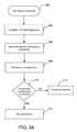
- FIG. 3A is a flowchart illustrating another embodiment of a process of providing data protection using Pseudowires.
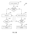
- FIG. 3B is a flowchart illustrating how the Pseudowire is used, according to some embodiments.
- FIG. 4 is a data structure diagram illustrating an embodiment of a Pseudowire protection configuration parameter that specifies several protection-related properties of the Pseudowire.
- FIG. 5 is a flowchart illustrating an example process of using the priorities during switchover.
- FIG. 6 is a diagram illustrating an example in which preemption takes place during a switchover process.
- the invention can be implemented in numerous ways, including as a process, an apparatus, a system, a composition of matter, a computer readable medium such as a computer readable storage medium or a computer network wherein program instructions are sent over optical or electronic communication links.
- these implementations, or any other form that the invention may take, may be referred to as techniques.
- a component such as a processor or a memory described as being configured to perform a task includes both a general component that is temporarily configured to perform the task at a given time or a specific component that is manufactured to perform the task.
- the order of the steps of disclosed processes may be altered within the scope of the invention.
- a Pseudowire protection configuration parameter is sent to a destination node.
- a Pseudowire configuration acknowledgment from the destination node is received. If a Pseudowire is allowed to be established according to the Pseudowire configuration acknowledgment, it is established based at least in part on the Pseudowire protection configuration parameter.
- the Pseudowire is established as a standby Pseudowire configured to protect one or more primary Pseudowires
- a primary Pseudowire fails to transfer network traffic for reasons such as network congestion, equipment failure, etc.
- network traffic that is originally designated to be transferred on the primary Pseudowire(s) is switched from the primary Pseudowire(s) to the standby Pseudowire.
- FIGS. 1A and 1B are block diagrams illustrating an embodiment of a single-hop Pseudowire system and an embodiment of a multi-hop Pseudowire system, respectively. Configuring and switching the Pseudowire will be discussed in more detail below.
- system 100 is a single-hop system where the nodes in the system all belong to the same carrier network.
- all network nodes and facility are under a common administrative control.
- a service provider company may own multiple carrier networks in different regions.
- a node refers to a networked device.
- the nodes in the system are provider edges (PEs) A, B, C, and D, which all belong to the same carrier network.
- Ingress data received by attachment circuits 112 of PE A designated for PE B may be sent via a label switched path (LSP) through PEs A, C, and B, or an LSP through PEs A, D, and B.
- LSP label switched path
- the first LSP comprises Pseudowires 102 , 104 and 106
- the second LSP comprises Pseudowires 108 and 110 .
- the Pseudowire connections between PEs are established using the Label Distribution Protocol (LDP).
- LDP Label Distribution Protocol
- the connections are based on LDP sessions.
- Each LDP session is to connect two local or remote nodes. There may be multiple paths interconnecting any two nodes in the network. Thus, for each LDP session, there may be multiple LDP Hello Adjacencies, one LDP Hello Adjacency per path.
- LDP is used as the communication protocol between nodes. Other appropriate protocols may also be used.
- system 150 is a multi-hop system since it includes multiple carrier networks.
- Carrier networks 1 - 6 form autonomous systems 16 , respectively.
- Each autonomous system includes one or more networks that are controlled by a carrier.
- three Pseudowires are shown in this example to transfer data between PE 1 A and PE 3 B: a first Pseudowire comprising a path via autonomous systems 1 , 2 , and 3 , a second Pseudowire comprising a path via autonomous systems 1 , 6 , and 3 , and a third Pseudowire comprising a path via autonomous systems 1 , 4 , 5 , and 3 .
- Other Pseudowire formations are possible.
- data packets to be sent via a particular Pseudowire are labeled with an identifier associated with the Pseudowire, forwarded on to the next provider edge on one Pseudowire segment, and forwarded again if necessary until the packets reach the destination node 3 B.
- FIG. 2 is a flowchart illustrating an embodiment of a process of providing data protection using Pseudowires.
- Process 200 may be implemented on a source node such as A or IA of systems 100 and 150 , or on an independent management agent that communicates with the source node. For purposes of illustration, the process is shown as implemented on a source node in the following example.
- the process initializes when a connection session is established between the source node and the destination node ( 202 ).
- a Pseudowire protection configuration parameter for configuring a Pseudowire based on the connection session is sent ( 204 ).
- the Pseudowire protection configuration parameter includes one or more fields that specify certain protection properties associated with the Pseudowire. It may be sent to the destination node or a management agent that communicates with the destination node. Details of the configuration parameter will be discussed further below.
- the destination node determines whether it will accept the Pseudowire protection configuration and allow a standby Pseudowire to be established. Depending on implementation, the destination node determines whether to accept the protection configuration based on factors such as traffic condition, number of existing Pseudowires, priority information, etc. The destination node may reject the protection request for a number of reasons. For example, the destination node does not support Pseudowire protection mechanism as described here. If a standby Pseudowire may be established, the destination node accepts it and configures the Pseudowire based at least in part on the configuration parameters.
- the destination node adds the Pseudowire to a table of Pseudowires.
- a corresponding Pseudowire configuration acknowledgment is generated, indicating whether the destination node has accepted the Pseudowire configuration.
- the Pseudowire configuration acknowledgment is sent to the source node.
- a MPLS label for the data packets traversing through the standby Pseudowire is assigned.
- the Pseudowire configuration acknowledgment is received ( 206 )
- it is examined to determine whether the Pseudowire configuration has been accepted ( 208 ). If, according to the Pseudowire configuration acknowledgment, the Pseudowire configuration has been accepted by the destination, a standby Pseudowire is established based at least in part on the Pseudowire protection configuration parameter and may be used as such ( 210 ). If, however, the Pseudowire configuration has not been accepted, the process performs appropriate exception handling, such as re-sending the Pseudowire protection configuration parameter ( 212 ).
- FIG. 3A is a flowchart illustrating another embodiment of a process of providing data protection using Pseudowires.
- Process 300 may be implemented on a PE, on an independent management agent, or the like. For purposes of illustration, in the following example, the process is initiated and carried out on a PE source node.
- Process 300 begins with the initialization of an LDP session ( 302 ).
- the source node exchanges messages with the destination node and establishes an LDP Hello Adjacency ( 304 ).
- a Pseudowire setup request that includes a Pseudowire protection configuration parameter is sent to the destination node (or its associated management agent), requesting that a standby Pseudowire be established over the LDP Hello Adjacency ( 306 ).
- multiple LDP Hello Adjacencies are available for Pseudowire setup, thus multiple setup requests are sent, and the destination node processes the requests and maps Pseudowires to appropriate LDP Hello Adjacencies.
- the source node dynamically determines which LDP Hello Adjacency among the available connections is to be configured as a standby Pseudowire, and directs its setup request accordingly.
- the dynamic determination may be based on, among other things, bandwidth availability on the adjacency path.
- the request is sent as a LDP Label Mapping Message.
- the configuration parameter is used to configure various properties of the Pseudowire, including protection type, protection scheme, priority, etc. Further details of the configuration parameters are discussed below.
- multiple LOP Hello Adjacencies are established and the source node sends multiple Pseudowire setup requests to configure Pseudowires over these LDP Hello Adjacencies.
- the destination node upon receiving a Pseudowire setup request, maps the request to the appropriate LDP Hello Adjacency. If the mapping is successful, the Pseudowire is established. Sometimes, however, the mapping and consequently the Pseudowire setup may fail for reasons such as network congestion, resource limitation, equipment failure, etc.
- the destination node sends a Pseudowire configuration acknowledgment to the source node.
- the Pseudowire configuration acknowledgment is an LDP acknowledgement indicating whether a particular Pseudowire has been successfully established.
- a standby Pseudowire is successfully established based at least in part on the Pseudowire protection configuration parameter, and the source and destination nodes can start using the standby Pseudowire to protect other Pseudowires ( 312 ). If, however, the acknowledgment indicates that the configuration has not been accepted and a Pseudowire has not been successfully established, appropriate exception handling measures such as resending the Pseudowire protection configuration parameter are taken ( 314 ).
- Process 300 is applicable to both single-hop and multi-hop systems.
- the source node and the destination node correspond to a source PE and a destination PE on the network and the process is used to configure a standby Pseudowire between the PEs.
- the process may be repeated by the PEs on various carrier networks to establish Pseudowire segments.
- PE 1 A can use process 300 to establish a Pseudowire segment with PE 6 A
- PE 6 A can use the same process to establish a Pseudowire segment with PE 6 B, which can use the same process to establish a Pseudowire segment with PE 3 B.
- FIG. 3B is a flowchart illustrating how the Pseudowire is used, according to some embodiments.
- Process 350 may be implemented on the source node, the destination node, or both.
- the designation of the Pseudowire is first determined ( 352 ). The designation may be configured by a system administrator, in an Pseudowire configuration process, or any other appropriate means. If the Pseudowire is designated as a primary Pseudowire, it is configured to carry network traffic ( 354 ).
- the nodes associated with the Pseudowire will attempt to switch the traffic over to the standby Pseudowire by sending a switchover request to the Pseudowire ( 358 ).
- a switchover request to the Pseudowire ( 358 ).
- whether the traffic on the primary Pseudowire can preempt the traffic on the standby Pseudowire and be switched over depends on priority configuration of the Pseudowires.
- the standby Pseudowire If it is designated as a standby Pseudowire, it is enters into standby mode to provide protection to one or more primary Pseudowires ( 360 ).
- the standby Pseudowire carries network traffic during normal operation. It is ready to take over traffic from the primary Pseudowire if necessary. If a switchover request is received from a primary Pseudowire ( 362 ), traffic on the primary Pseudowire is switched over to the standby Pseudowire. In some embodiments, the switchover only occurs if the priority comparison of the primary and standby Pseudowires indicates the switchover is allowed.
- the source node can send a withdraw request over the Pseudowire and the destination node disassociates the Pseudowire with the LDP Hello Adjacency to break the Pseudowire connection.
- FIG. 4 is a data structure diagram illustrating an embodiment of a Pseudowire protection configuration parameter that specifies several protection-related properties of the Pseudowire.
- Pseudowire protection configuration parameter 400 includes four fields: protection scheme, protection type, domain type, and priority.
- a field may have one or more subfields.
- the priority field is shown to include a holding priority and a setup priority.
- One or more of the fields and/or subfields may be used in various embodiments. Other appropriate fields may also be implemented.
- the fields are numerical values that map to appropriate property values.
- one of the following Pseudowire protection schemes is used to set up the Pseudowires: 1+1, 1:1, 1:N or M:N.
- the protection scheme field is used to indicate which protection scheme is used in the system setup.
- a specific protection scheme corresponds to a field value. For example, 1+1 maps to 0, 1:1 maps to 1, and so on.
- 1+1 maps to 0, 1:1 maps to 1, and so on.
- 1+1 protection scheme the same traffic is sent over two parallel Pseudowires and the receiver selects one traffic stream at a time.
- one Pseudowire is used is used to protect another Pseudowire.
- a 1:N system e.g. MPLS Facility Backup
- one Pseudowire is used to protect N other Pseudowires
- M Pseudowires are used to protect N other Pseudowires.
- the protection type field is used to configure the standby mode of the Pseudowire.
- cold, warm, and hot standby modes are supported. Other appropriate standby modes may be implemented in other embodiments.
- a standby Pseudowire in cold standby mode configuration, once network failure on a Pseudowire carrying network traffic is detected, a standby Pseudowire is selected from the remaining functional Pseudowires, and traffic is redirected to the standby Pseudowire.
- one or more standby Pseudowires are established before any network failure has occurred. These standby Pseudowires, however, are not maintained or used to transport data until a network failure is detected.
- the source or destination nodes Upon failure detection, the source or destination nodes will modify the data-plane and switch data traffic over to the standby Pseudowire(s).
- the standby Pseudowire(s) In some embodiments with hot standby mode configuration, one or more standby Pseudowires are pre-established and maintained at both control-plane and data-plane, so that once a network failure is detected, data traffic is directly switched over to the standby Pseudowire(s).
- the domain type field indicates whether the Pseudowire is configured in a single-hop environment where all the nodes of the Pseudowire belong to the same carrier network, or a multi-hop environment where the Pseudowire includes nodes on several carrier networks. This is because the intermediate may process single-hop and multi-hop Pseudowire differently.
- the priority field indicates the preference level of a Pseudowire in preempting other Pseudowires during switchover.
- the edge nodes will preferentially provide protection according to the priority setting of the Pseudowires.
- the priority field includes two subfields: a holding priority and a setup priority.
- the holding priority indicates the relative priority of a currently active Pseudowire with respect to other Pseudowires when the latter attempt to preempt the former's use of the data link. Stated another way, it determines how easily a currently active Pseudowire gives up its hold on a data link upon request.
- the setup priority indicates the relative priority of a Pseudowire during the setup process.
- FIG. 5 is a flowchart illustrating an example process of using the priorities during switchover.
- Process 500 may be implemented on an edge node, an independent management agent, or the like.
- process 500 initiates when a network failure has been detected ( 502 ). It is determined whether preemption is required ( 504 ). Preemption is required when the failed link carries more Pseudowire traffic than the available bandwidth on the standby link. If preemption is not required, the Pseudowire(s) may directly switchover ( 506 ). If, however, preemption is required, the setup priorities of the Pseudowires on the failed link are compared and the Pseudowire with the highest setup priority is selected ( 508 ).
- the setup priority of the selected Pseudowire is compared to the holding priority of the standby Pseudowire ( 510 ). If the setup priority is greater than the holding priority, traffic on the selected Pseudowire is switched over to the standby Pseudowire ( 506 ). If, however, the setup priority is no greater than the holding priority, no switchover takes place and the standby Pseudowire continues to transfer its own data and the data of the failed Pseudowires is lost ( 514 ).
- FIG. 6 is a diagram illustrating an example in which preemption takes place during a switchover operation.
- Pseudowires 600 , 602 and 604 are active, primary Pseudowires carrying traffic.
- Pseudowire 604 is used as the standby.
- Pseudowire 600 has a holding priority and a setup priority of 10 and 11, respectively, Pseudowire 602 has priorities of 11 and 12, and Pseudowire 604 has priorities of 9 and 9.
- the link on which Pseudowires 600 and 602 operate fails, the nodes will initiate switchover using Pseudowire 604 .
- a comparison of the setup priority of Pseudowires 600 and 602 indicates that Pseudowire 602 has a higher setup priority, thus 602 is given preference in the switchover.
- the setup priority of Pseudowire 602 is compared with the holding priority of Pseudowire 604 . Since 602 's setup priority is greater than 604 's holding priority, data on 602 preempts data on 604 and takes over the link.
- Pseudowire protection improves the reliability of Pseudowire services.
- Pseudowires are better controlled by appropriately configuring the properties of Pseudowires and without requiring significant changes to existing protocols and devices.
Abstract
Description
Claims (18)
Priority Applications (3)
| Application Number | Priority Date | Filing Date | Title |
|---|---|---|---|
| US14/050,078 US9749249B2 (en) | 2005-02-14 | 2013-10-09 | Pseudowire protection using a standby pseudowire |
| US15/687,633 US20170353388A1 (en) | 2005-02-14 | 2017-08-28 | Pseudowire protection using a standby pseudowire |
| US16/927,909 US20210176178A1 (en) | 2005-02-14 | 2020-07-13 | Pseudowire protection using a standby pseudowire |
Applications Claiming Priority (4)
| Application Number | Priority Date | Filing Date | Title |
|---|---|---|---|
| US65306505P | 2005-02-14 | 2005-02-14 | |
| US11/354,569 US7940652B1 (en) | 2005-02-14 | 2006-02-14 | Pseudowire protection using a standby pseudowire |
| US13/038,282 US8582427B2 (en) | 2005-02-14 | 2011-03-01 | Pseudowire protection using a standby Pseudowire |
| US14/050,078 US9749249B2 (en) | 2005-02-14 | 2013-10-09 | Pseudowire protection using a standby pseudowire |
Related Parent Applications (1)
| Application Number | Title | Priority Date | Filing Date |
|---|---|---|---|
| US13/038,282 Continuation US8582427B2 (en) | 2005-02-14 | 2011-03-01 | Pseudowire protection using a standby Pseudowire |
Related Child Applications (1)
| Application Number | Title | Priority Date | Filing Date |
|---|---|---|---|
| US15/687,633 Continuation US20170353388A1 (en) | 2005-02-14 | 2017-08-28 | Pseudowire protection using a standby pseudowire |
Publications (2)
| Publication Number | Publication Date |
|---|---|
| US20140105002A1 US20140105002A1 (en) | 2014-04-17 |
| US9749249B2 true US9749249B2 (en) | 2017-08-29 |
Family
ID=43928307
Family Applications (5)
| Application Number | Title | Priority Date | Filing Date |
|---|---|---|---|
| US11/354,569 Active 2028-06-24 US7940652B1 (en) | 2005-02-14 | 2006-02-14 | Pseudowire protection using a standby pseudowire |
| US13/038,282 Active 2026-12-15 US8582427B2 (en) | 2005-02-14 | 2011-03-01 | Pseudowire protection using a standby Pseudowire |
| US14/050,078 Active US9749249B2 (en) | 2005-02-14 | 2013-10-09 | Pseudowire protection using a standby pseudowire |
| US15/687,633 Abandoned US20170353388A1 (en) | 2005-02-14 | 2017-08-28 | Pseudowire protection using a standby pseudowire |
| US16/927,909 Abandoned US20210176178A1 (en) | 2005-02-14 | 2020-07-13 | Pseudowire protection using a standby pseudowire |
Family Applications Before (2)
| Application Number | Title | Priority Date | Filing Date |
|---|---|---|---|
| US11/354,569 Active 2028-06-24 US7940652B1 (en) | 2005-02-14 | 2006-02-14 | Pseudowire protection using a standby pseudowire |
| US13/038,282 Active 2026-12-15 US8582427B2 (en) | 2005-02-14 | 2011-03-01 | Pseudowire protection using a standby Pseudowire |
Family Applications After (2)
| Application Number | Title | Priority Date | Filing Date |
|---|---|---|---|
| US15/687,633 Abandoned US20170353388A1 (en) | 2005-02-14 | 2017-08-28 | Pseudowire protection using a standby pseudowire |
| US16/927,909 Abandoned US20210176178A1 (en) | 2005-02-14 | 2020-07-13 | Pseudowire protection using a standby pseudowire |
Country Status (1)
| Country | Link |
|---|---|
| US (5) | US7940652B1 (en) |
Cited By (1)
| Publication number | Priority date | Publication date | Assignee | Title |
|---|---|---|---|---|
| US10862743B2 (en) * | 2019-03-18 | 2020-12-08 | Ciena Corporation | Systems and methods to detect, locate, and switch based on signal degrade on multi-segment pseudowires |
Families Citing this family (13)
| Publication number | Priority date | Publication date | Assignee | Title |
|---|---|---|---|---|
| US7940652B1 (en) * | 2005-02-14 | 2011-05-10 | Brixham Solutions Ltd. | Pseudowire protection using a standby pseudowire |
| US9124486B2 (en) * | 2005-08-26 | 2015-09-01 | RPX Clearinghouse, LLC | Method for establishing multi segment pseudowire across domains having different pseudowire signaling protocol |
| US8724451B2 (en) * | 2008-06-27 | 2014-05-13 | France Telecom | Method for protecting a pseudo-wire |
| US8144575B2 (en) * | 2009-06-30 | 2012-03-27 | Juniper Networks, Inc. | Redundant pseudowires for border gateway patrol-based virtual private local area network service multi-homing environments |
| US8553533B2 (en) * | 2010-12-10 | 2013-10-08 | Cisco Technology, Inc. | System and method for providing improved failover performance for pseudowires |
| US9722916B2 (en) * | 2013-09-30 | 2017-08-01 | Cisco Technology, Inc. | Data-plane driven fast protection mechanism for MPLS pseudowire services |
| BR112016012417B1 (en) | 2013-12-18 | 2023-04-11 | Hfi Innovation Inc | METHOD AND APPARATUS FOR INITIALIZING AND MANAGING A PALETTE |
| CN106031171B (en) * | 2013-12-27 | 2019-08-30 | 联发科技股份有限公司 | Method and apparatus with the palette coding predicted across block |
| WO2015096808A1 (en) | 2013-12-27 | 2015-07-02 | Mediatek Inc. | Method and apparatus for syntax redundancy removal in palette coding |
| CN106063270A (en) | 2013-12-27 | 2016-10-26 | 寰发股份有限公司 | Method and apparatus for major color index map coding |
| US10484696B2 (en) | 2014-01-07 | 2019-11-19 | Mediatek Inc. | Method and apparatus for color index prediction |
| CN107846356B (en) * | 2016-09-19 | 2020-02-11 | 新华三技术有限公司 | Method and device for fast switching between main pseudo wire and standby pseudo wire |
| CN110071830B (en) * | 2019-04-15 | 2020-03-06 | 北京华三通信技术有限公司 | Pseudo wire back switching method and device |
Citations (50)
| Publication number | Priority date | Publication date | Assignee | Title |
|---|---|---|---|---|
| US5920705A (en) | 1996-01-31 | 1999-07-06 | Nokia Ip, Inc. | Method and apparatus for dynamically shifting between routing and switching packets in a transmission network |
| US6167051A (en) | 1996-07-11 | 2000-12-26 | Kabushiki Kaisha Toshiba | Network node and method of packet transfer |
| US20010021175A1 (en) | 2000-03-13 | 2001-09-13 | Henry Haverinen | Load balancing in telecommunications system supporting mobile IP |
| US20010023453A1 (en) | 2000-03-15 | 2001-09-20 | Telefonaktiebolaget Lm Ericsson (Publ) | Method and arrangement for flow control |
| US6347088B1 (en) | 1997-10-28 | 2002-02-12 | Fujitsu Limited | Apparatus for transmitting cells, with audio interwork function |
| US6430184B1 (en) | 1998-04-10 | 2002-08-06 | Top Layer Networks, Inc. | System and process for GHIH-speed pattern matching for application-level switching of data packets |
| US20020112072A1 (en) | 2001-02-12 | 2002-08-15 | Maple Optical Systems, Inc. | System and method for fast-rerouting of data in a data communication network |
| US20020141393A1 (en) | 2001-04-02 | 2002-10-03 | Eriksson Goran A.P. | Concurrent use of communication paths in a multi-path access link to an IP network |
| US20020146026A1 (en) | 2000-05-14 | 2002-10-10 | Brian Unitt | Data stream filtering apparatus & method |
| US20030002482A1 (en) | 1995-10-05 | 2003-01-02 | Kubler Joseph J. | Hierarchical data collection network supporting packetized voice communications among wireless terminals and telephones |
| US20030039237A1 (en) | 1997-09-25 | 2003-02-27 | Jan E Forslow | Common access between a mobile communications network and an external network with selectable packet-switched and circuit-switched services |
| US6546427B1 (en) | 1999-06-18 | 2003-04-08 | International Business Machines Corp. | Streaming multimedia network with automatically switchable content sources |
| US6574477B1 (en) | 1999-10-06 | 2003-06-03 | Lucent Technologies Inc. | Dynamic load balancing during message processing in a wireless communication service network |
| US20030117950A1 (en) | 2001-12-26 | 2003-06-26 | Huang Gail G | Link redial for mesh protection |
| US6621793B2 (en) | 2000-05-22 | 2003-09-16 | Telefonaktiebolaget Lm Ericsson (Publ) | Application influenced policy |
| US6665273B1 (en) | 2000-01-11 | 2003-12-16 | Cisco Technology, Inc. | Dynamically adjusting multiprotocol label switching (MPLS) traffic engineering tunnel bandwidth |
| US6680943B1 (en) | 1999-10-01 | 2004-01-20 | Nortel Networks Limited | Establishing bi-directional communication sessions across a communications network |
| US20040105459A1 (en) | 2002-11-30 | 2004-06-03 | Raghu Mannam | Method and a system to build efficient communications networks in which MPLS functionality is incorporated within the SONET/SDH/OTN transport equipment by performing it in the GFP layer |
| US6751684B2 (en) | 2000-12-21 | 2004-06-15 | Jonathan M. Owen | System and method of allocating bandwidth to a plurality of devices interconnected by a plurality of point-to-point communication links |
| US20040114595A1 (en) | 2001-04-19 | 2004-06-17 | Masami Doukai | Restoration and protection method and an apparatus thereof |
| US20040133692A1 (en) * | 2003-01-07 | 2004-07-08 | Hexago Inc. | Method and apparatus for connecting IPV6 devices through an IPv4 network and a network address translator (NAT) using a tunnel setup protocol |
| US20040156313A1 (en) * | 2003-02-03 | 2004-08-12 | Hofmeister Ralph Theodore | Method and apparatus for performing data flow ingress/egress admission control in a provider network |
| US20040174865A1 (en) | 2001-06-26 | 2004-09-09 | O'neill Alan | Messages and control methods for controlling resource allocation and flow admission control in a mobile communications system |
| US6813271B1 (en) | 1999-09-30 | 2004-11-02 | Nortel Networks Limited | Satellite communications system and method of supporting ATM cell transmissions in a DVB environment |
| US20040252717A1 (en) | 2003-06-13 | 2004-12-16 | Corrigent Systems Ltd. | Multiprotocol media conversion |
| US6845389B1 (en) | 2000-05-12 | 2005-01-18 | Nortel Networks Limited | System and method for broadband multi-user communication sessions |
| US20050018605A1 (en) | 2002-07-22 | 2005-01-27 | Richard Foote | Multiprotocol label switching (MPLS) edge service extraction |
| US20050044262A1 (en) | 2002-11-21 | 2005-02-24 | Cisco Technology, Inc. | System and method for interconnecting heterogeneous layer 2 VPN applications |
| US20050220148A1 (en) | 2004-04-05 | 2005-10-06 | Delregno Nick | System and method for transporting time-division multiplexed communications through a packet-switched access network |
| US20050237927A1 (en) | 2003-05-14 | 2005-10-27 | Shinya Kano | Transmission apparatus |
| US20060002423A1 (en) | 2004-06-30 | 2006-01-05 | Rembert James W | Methods, systems, and computer program products for direct interworking between pseudo wires associated with different services |
| US6985488B2 (en) | 2003-01-15 | 2006-01-10 | Ciena Corporation | Method and apparatus for transporting packet data over an optical network |
| US20060018252A1 (en) | 2004-07-20 | 2006-01-26 | Alcatel | Load balancing in a virtual private network |
| US20060047851A1 (en) | 2004-08-25 | 2006-03-02 | Cisco Technoloy, Inc. | Computer network with point-to-point pseudowire redundancy |
| US20060046658A1 (en) | 2002-09-05 | 2006-03-02 | Cruz Rene L | Scheduling methods for wireless networks |
| US20060090008A1 (en) | 2004-10-21 | 2006-04-27 | Jim Guichard | Pseudowire termination directly on a router |
| US7050396B1 (en) | 2000-11-30 | 2006-05-23 | Cisco Technology, Inc. | Method and apparatus for automatically establishing bi-directional differentiated services treatment of flows in a network |
| US20060146832A1 (en) | 2005-01-05 | 2006-07-06 | CISCO TECHNOLOGY, INC. A Corporation of the state of California | Method and system for transporting data using pseudowire circuits over a bridged network |
| US20060233167A1 (en) | 2005-04-19 | 2006-10-19 | Alcatel | Negotiation of datapath treatment for end-to-end interworked network traffic |
| US7180866B1 (en) * | 2002-07-11 | 2007-02-20 | Nortel Networks Limited | Rerouting in connection-oriented communication networks and communication systems |
| US20070053366A1 (en) | 2005-09-08 | 2007-03-08 | Booth Earl H Iii | Layer-two interworking applied to L2-L3 pseudowires |
| US7200104B2 (en) | 1999-01-15 | 2007-04-03 | Cisco Technology, Inc. | Method for restoring a virtual path in an optical network using 1+1 protection |
| US20070127479A1 (en) | 2005-12-05 | 2007-06-07 | David Sinicrope | A method and arrangement for distributed pseudo-wire signaling |
| US20070206607A1 (en) | 2006-03-06 | 2007-09-06 | Chapman John T | Resource reservation and admission control for IP network |
| US20080031129A1 (en) | 2006-08-07 | 2008-02-07 | Jim Arseneault | Smart Ethernet edge networking system |
| US7363534B1 (en) * | 2002-09-30 | 2008-04-22 | Cisco Technology, Inc. | Method and system for stateful switch-over in a high-availability point to point system |
| US7436782B2 (en) | 2004-03-25 | 2008-10-14 | Alcatel Lucent | Full mesh LSP and full mesh T-LDP provisioning between provider edge routers in support of Layer-2 and Layer-3 virtual private network services |
| US7697528B2 (en) | 2005-11-01 | 2010-04-13 | Nortel Networks Limited | Multilink trunking for encapsulated traffic |
| US7804767B1 (en) * | 1999-10-25 | 2010-09-28 | Tellabs Operations, Inc. | Protection/restoration of MPLS networks |
| US7940652B1 (en) * | 2005-02-14 | 2011-05-10 | Brixham Solutions Ltd. | Pseudowire protection using a standby pseudowire |
Family Cites Families (1)
| Publication number | Priority date | Publication date | Assignee | Title |
|---|---|---|---|---|
| US7733876B2 (en) * | 2005-02-11 | 2010-06-08 | Cisco Technology, Inc. | Inter-autonomous-system virtual private network with autodiscovery and connection signaling |
-
2006
- 2006-02-14 US US11/354,569 patent/US7940652B1/en active Active
-
2011
- 2011-03-01 US US13/038,282 patent/US8582427B2/en active Active
-
2013
- 2013-10-09 US US14/050,078 patent/US9749249B2/en active Active
-
2017
- 2017-08-28 US US15/687,633 patent/US20170353388A1/en not_active Abandoned
-
2020
- 2020-07-13 US US16/927,909 patent/US20210176178A1/en not_active Abandoned
Patent Citations (51)
| Publication number | Priority date | Publication date | Assignee | Title |
|---|---|---|---|---|
| US20030002482A1 (en) | 1995-10-05 | 2003-01-02 | Kubler Joseph J. | Hierarchical data collection network supporting packetized voice communications among wireless terminals and telephones |
| US5920705A (en) | 1996-01-31 | 1999-07-06 | Nokia Ip, Inc. | Method and apparatus for dynamically shifting between routing and switching packets in a transmission network |
| US6167051A (en) | 1996-07-11 | 2000-12-26 | Kabushiki Kaisha Toshiba | Network node and method of packet transfer |
| US20030039237A1 (en) | 1997-09-25 | 2003-02-27 | Jan E Forslow | Common access between a mobile communications network and an external network with selectable packet-switched and circuit-switched services |
| US6347088B1 (en) | 1997-10-28 | 2002-02-12 | Fujitsu Limited | Apparatus for transmitting cells, with audio interwork function |
| US6430184B1 (en) | 1998-04-10 | 2002-08-06 | Top Layer Networks, Inc. | System and process for GHIH-speed pattern matching for application-level switching of data packets |
| US7200104B2 (en) | 1999-01-15 | 2007-04-03 | Cisco Technology, Inc. | Method for restoring a virtual path in an optical network using 1+1 protection |
| US6546427B1 (en) | 1999-06-18 | 2003-04-08 | International Business Machines Corp. | Streaming multimedia network with automatically switchable content sources |
| US6813271B1 (en) | 1999-09-30 | 2004-11-02 | Nortel Networks Limited | Satellite communications system and method of supporting ATM cell transmissions in a DVB environment |
| US6680943B1 (en) | 1999-10-01 | 2004-01-20 | Nortel Networks Limited | Establishing bi-directional communication sessions across a communications network |
| US6574477B1 (en) | 1999-10-06 | 2003-06-03 | Lucent Technologies Inc. | Dynamic load balancing during message processing in a wireless communication service network |
| US7804767B1 (en) * | 1999-10-25 | 2010-09-28 | Tellabs Operations, Inc. | Protection/restoration of MPLS networks |
| US6665273B1 (en) | 2000-01-11 | 2003-12-16 | Cisco Technology, Inc. | Dynamically adjusting multiprotocol label switching (MPLS) traffic engineering tunnel bandwidth |
| US20010021175A1 (en) | 2000-03-13 | 2001-09-13 | Henry Haverinen | Load balancing in telecommunications system supporting mobile IP |
| US20010023453A1 (en) | 2000-03-15 | 2001-09-20 | Telefonaktiebolaget Lm Ericsson (Publ) | Method and arrangement for flow control |
| US6845389B1 (en) | 2000-05-12 | 2005-01-18 | Nortel Networks Limited | System and method for broadband multi-user communication sessions |
| US20020146026A1 (en) | 2000-05-14 | 2002-10-10 | Brian Unitt | Data stream filtering apparatus & method |
| US6621793B2 (en) | 2000-05-22 | 2003-09-16 | Telefonaktiebolaget Lm Ericsson (Publ) | Application influenced policy |
| US7050396B1 (en) | 2000-11-30 | 2006-05-23 | Cisco Technology, Inc. | Method and apparatus for automatically establishing bi-directional differentiated services treatment of flows in a network |
| US6751684B2 (en) | 2000-12-21 | 2004-06-15 | Jonathan M. Owen | System and method of allocating bandwidth to a plurality of devices interconnected by a plurality of point-to-point communication links |
| US20020112072A1 (en) | 2001-02-12 | 2002-08-15 | Maple Optical Systems, Inc. | System and method for fast-rerouting of data in a data communication network |
| US20020141393A1 (en) | 2001-04-02 | 2002-10-03 | Eriksson Goran A.P. | Concurrent use of communication paths in a multi-path access link to an IP network |
| US20040114595A1 (en) | 2001-04-19 | 2004-06-17 | Masami Doukai | Restoration and protection method and an apparatus thereof |
| US20040174865A1 (en) | 2001-06-26 | 2004-09-09 | O'neill Alan | Messages and control methods for controlling resource allocation and flow admission control in a mobile communications system |
| US20030117950A1 (en) | 2001-12-26 | 2003-06-26 | Huang Gail G | Link redial for mesh protection |
| US7180866B1 (en) * | 2002-07-11 | 2007-02-20 | Nortel Networks Limited | Rerouting in connection-oriented communication networks and communication systems |
| US20050018605A1 (en) | 2002-07-22 | 2005-01-27 | Richard Foote | Multiprotocol label switching (MPLS) edge service extraction |
| US20060046658A1 (en) | 2002-09-05 | 2006-03-02 | Cruz Rene L | Scheduling methods for wireless networks |
| US7363534B1 (en) * | 2002-09-30 | 2008-04-22 | Cisco Technology, Inc. | Method and system for stateful switch-over in a high-availability point to point system |
| US20050044262A1 (en) | 2002-11-21 | 2005-02-24 | Cisco Technology, Inc. | System and method for interconnecting heterogeneous layer 2 VPN applications |
| US20040105459A1 (en) | 2002-11-30 | 2004-06-03 | Raghu Mannam | Method and a system to build efficient communications networks in which MPLS functionality is incorporated within the SONET/SDH/OTN transport equipment by performing it in the GFP layer |
| US20040133692A1 (en) * | 2003-01-07 | 2004-07-08 | Hexago Inc. | Method and apparatus for connecting IPV6 devices through an IPv4 network and a network address translator (NAT) using a tunnel setup protocol |
| US6985488B2 (en) | 2003-01-15 | 2006-01-10 | Ciena Corporation | Method and apparatus for transporting packet data over an optical network |
| US20040156313A1 (en) * | 2003-02-03 | 2004-08-12 | Hofmeister Ralph Theodore | Method and apparatus for performing data flow ingress/egress admission control in a provider network |
| US20050237927A1 (en) | 2003-05-14 | 2005-10-27 | Shinya Kano | Transmission apparatus |
| US20040252717A1 (en) | 2003-06-13 | 2004-12-16 | Corrigent Systems Ltd. | Multiprotocol media conversion |
| US7436782B2 (en) | 2004-03-25 | 2008-10-14 | Alcatel Lucent | Full mesh LSP and full mesh T-LDP provisioning between provider edge routers in support of Layer-2 and Layer-3 virtual private network services |
| US20050220148A1 (en) | 2004-04-05 | 2005-10-06 | Delregno Nick | System and method for transporting time-division multiplexed communications through a packet-switched access network |
| US20060002423A1 (en) | 2004-06-30 | 2006-01-05 | Rembert James W | Methods, systems, and computer program products for direct interworking between pseudo wires associated with different services |
| US20060018252A1 (en) | 2004-07-20 | 2006-01-26 | Alcatel | Load balancing in a virtual private network |
| US20060047851A1 (en) | 2004-08-25 | 2006-03-02 | Cisco Technoloy, Inc. | Computer network with point-to-point pseudowire redundancy |
| US20060090008A1 (en) | 2004-10-21 | 2006-04-27 | Jim Guichard | Pseudowire termination directly on a router |
| US20060146832A1 (en) | 2005-01-05 | 2006-07-06 | CISCO TECHNOLOGY, INC. A Corporation of the state of California | Method and system for transporting data using pseudowire circuits over a bridged network |
| US7940652B1 (en) * | 2005-02-14 | 2011-05-10 | Brixham Solutions Ltd. | Pseudowire protection using a standby pseudowire |
| US8582427B2 (en) * | 2005-02-14 | 2013-11-12 | Brixham Solutions Ltd. | Pseudowire protection using a standby Pseudowire |
| US20060233167A1 (en) | 2005-04-19 | 2006-10-19 | Alcatel | Negotiation of datapath treatment for end-to-end interworked network traffic |
| US20070053366A1 (en) | 2005-09-08 | 2007-03-08 | Booth Earl H Iii | Layer-two interworking applied to L2-L3 pseudowires |
| US7697528B2 (en) | 2005-11-01 | 2010-04-13 | Nortel Networks Limited | Multilink trunking for encapsulated traffic |
| US20070127479A1 (en) | 2005-12-05 | 2007-06-07 | David Sinicrope | A method and arrangement for distributed pseudo-wire signaling |
| US20070206607A1 (en) | 2006-03-06 | 2007-09-06 | Chapman John T | Resource reservation and admission control for IP network |
| US20080031129A1 (en) | 2006-08-07 | 2008-02-07 | Jim Arseneault | Smart Ethernet edge networking system |
Non-Patent Citations (23)
| Title |
|---|
| Afferton, et al., Ethernet Transport Over Wide Area Netowrks, Packet-Aware Transport for Metro Networks, IEEE Communications Magazine, pp. 120-127, Mar. 2004. |
| Anderson, et al., LDP Specification, Network Working Group, Jan. 2001. |
| Blake, et al., "An Architecture for Differentiated Services," Network Working Group, Dec. 1998. |
| Braden, et al., "Integrated Services in the Internet Architecture: an overview", Network Working Group, Jun. 1994. |
| Bryant, et al., "Pseudo Wire Emulation Edge-to-Edge (PWE3) Archicture," Network Working Group, Mar. 2005. |
| Chen, "The LSP Protection/Restoration Mechanism in GMPLS" Internet Citation (online) Oct. 2002 (Oct. 1, 2002) XP00223. Retrieved from the internet URL: http://www.site.uottawa.ca/˜bochmann/dsrg/PublicDocuments/Master-theses/Chen, %20Ziying%20%20-%202002.pdf. |
| Harry Newton, "Newton's Telecom Dictionary", 23rd Updated and Expanded Edition, p. 825, p. 239, Flatiron Publishing, New York, Mar. 2007. |
| Martini, et al., "Pseudowire Setup and Maintenance Using LDP", Network Working Group, Mar. 2005. |
| Martini, et al., Dynamic Placement of Multi Segment Pseudo Wires, PWE3 Working Group, Jun. 2006. |
| Martini, et al., Encapsulation Methods for Transport of Ethernet Over MPLS Networks, Network Working Group, Apr. 2006. |
| Martini, et al., Encapsulation Methods for Transport of Frame Relay Over MPLS Networks, Network Working Group, Feb. 2006. |
| Martini, et al., Internet Draft, Segmented Pseudo Wire, Network Working Group, Jul. 2007. |
| Martini, et al., Pseudowire Setup and Maintenance using the Label Distribution Protocol (LDP), Network Working Group, Apr. 2006. |
| McPherson, et al., Pseudowire Wmulation Edge to Edge (PWE3) Jun. 13, 2007, http://www.ietf.org/html.charters/pwe3-carter.html. |
| Metz, et al., Pseudowire Attachment Identifiers for Aggregation and VPN Autodiscovery, PWE3 Working Group, Feb. 25, 2006. |
| Office Action dated Mar. 1, 2013 for U.S. Appl. No. 13/038,282, 12 pages. |
| Pan, et al., Internet Draft, Pseudo Wire Protection, Jul. 2006. |
| Pan, Internet Draft, Dry-Martini: Supporting Pseudo-wires in Sub-IP Access Networks, Network Working Group, Jul. 2005. |
| Rosen, et al., BGP-MPLS IP Virtual Private Networks (VPN), Network Working Group, Feb. 2006. |
| Rosen, et al., Internet Draft, PWE3 Congestion Control Framework, Network Working Group, Mar. 2004. |
| Shah, et al., Internet Draft, ARP Meditation for IP Interworking of Layer 2 VPN, L2VPN Working Group, Jul. 2007. |
| Theimer, et al., "Requirements for OAM Funcionality in MPLS", Oct. 1999, Watersprings. |
| Vasseur, et al., Path Computation Element (pce), May 9, 2007, http://www.ietf.org/html.charters/pce.charter.html. |
Cited By (1)
| Publication number | Priority date | Publication date | Assignee | Title |
|---|---|---|---|---|
| US10862743B2 (en) * | 2019-03-18 | 2020-12-08 | Ciena Corporation | Systems and methods to detect, locate, and switch based on signal degrade on multi-segment pseudowires |
Also Published As
| Publication number | Publication date |
|---|---|
| US7940652B1 (en) | 2011-05-10 |
| US8582427B2 (en) | 2013-11-12 |
| US20140105002A1 (en) | 2014-04-17 |
| US20210176178A1 (en) | 2021-06-10 |
| US20170353388A1 (en) | 2017-12-07 |
| US20110199896A1 (en) | 2011-08-18 |
Similar Documents
| Publication | Publication Date | Title |
|---|---|---|
| US20210176178A1 (en) | Pseudowire protection using a standby pseudowire | |
| US10432514B2 (en) | Multiprotocol label switching traffic engineering tunnel establishing method and device | |
| ES2363410T3 (en) | METHOD, DEVICE AND SYSTEM FOR TRAFFIC SWITCHING IN MULTIPROTOCOL SWITCHING TRAFFIC ENGINEERING BY LABEL. | |
| US7765306B2 (en) | Technique for enabling bidirectional forwarding detection between edge devices in a computer network | |
| US7693047B2 (en) | System and method for PE-node protection | |
| US8082340B2 (en) | Technique for distinguishing between link and node failure using bidirectional forwarding detection (BFD) | |
| US7869345B2 (en) | Loop prevention techniques using encapsulation manipulation of IP/MPLS field | |
| US9722916B2 (en) | Data-plane driven fast protection mechanism for MPLS pseudowire services | |
| EP2498454B1 (en) | Method, device and system for processing service traffic based on pseudo wires | |
| EP1111860B1 (en) | Automatic protection switching using link-level redundancy supporting multi-protocol label switching | |
| EP2364539B1 (en) | A system and method of implementing lightweight not-via ip fast reroutes in a telecommunications network | |
| US20020116669A1 (en) | System and method for fault notification in a data communication network | |
| US8576708B2 (en) | System and method for link protection using shared SRLG association | |
| US20100118732A1 (en) | Loop prevention technique for mpls using service labels | |
| US20080123651A1 (en) | Path diversity for customer-to-customer traffic | |
| US20110182185A1 (en) | Methods for establishing a traffic connection and an associated monitoring connection | |
| EP3687113B1 (en) | Method and apparatus for establishing hard pipe in a network | |
| WO2010007603A2 (en) | Establishing pseudowires in packet switching networks | |
| WO2008119277A1 (en) | A method and device for implementing mpls te on vlan interface | |
| EP3065364B1 (en) | Synchronization method and apparatus for interface parameters | |
| EP1601139A1 (en) | Method and apparatus for routing traffic through a communications network | |
| CN115499369A (en) | Path protection method and device |
Legal Events
| Date | Code | Title | Description |
|---|---|---|---|
| AS | Assignment |
Owner name: BRIXHAM SOLUTIONS LTD., VIRGIN ISLANDS, BRITISH Free format text: ASSIGNMENT OF ASSIGNORS INTEREST;ASSIGNOR:HAMMERHEAD SYSTEMS, INC.;REEL/FRAME:031933/0846 Effective date: 20100108 |
|
| STCF | Information on status: patent grant |
Free format text: PATENTED CASE |
|
| AS | Assignment |
Owner name: GLOBAL INNOVATION AGGREGATORS LLC., CALIFORNIA Free format text: ASSIGNMENT OF ASSIGNORS INTEREST;ASSIGNOR:BRIXHAM SOLUTIONS LTD.;REEL/FRAME:043312/0218 Effective date: 20170627 |
|
| AS | Assignment |
Owner name: K.MIZRA LLC, CALIFORNIA Free format text: ASSIGNMENT OF ASSIGNORS INTEREST;ASSIGNOR:GLOBAL INNOVATION AGGREGATORS, LLC;REEL/FRAME:051579/0773 Effective date: 20191224 |
|
| MAFP | Maintenance fee payment |
Free format text: PAYMENT OF MAINTENANCE FEE, 4TH YEAR, LARGE ENTITY (ORIGINAL EVENT CODE: M1551); ENTITY STATUS OF PATENT OWNER: LARGE ENTITY Year of fee payment: 4 |