US9720404B2 - Gateway offering logical model mapped to independent underlying networks - Google Patents
Gateway offering logical model mapped to independent underlying networks Download PDFInfo
- Publication number
- US9720404B2 US9720404B2 US14/269,903 US201414269903A US9720404B2 US 9720404 B2 US9720404 B2 US 9720404B2 US 201414269903 A US201414269903 A US 201414269903A US 9720404 B2 US9720404 B2 US 9720404B2
- Authority
- US
- United States
- Prior art keywords
- process control
- network
- interface
- legacy
- gateway
- Prior art date
- Legal status (The legal status is an assumption and is not a legal conclusion. Google has not performed a legal analysis and makes no representation as to the accuracy of the status listed.)
- Active, expires
Links
Images


Classifications
-
- G—PHYSICS
- G05—CONTROLLING; REGULATING
- G05B—CONTROL OR REGULATING SYSTEMS IN GENERAL; FUNCTIONAL ELEMENTS OF SUCH SYSTEMS; MONITORING OR TESTING ARRANGEMENTS FOR SUCH SYSTEMS OR ELEMENTS
- G05B19/00—Programme-control systems
- G05B19/02—Programme-control systems electric
- G05B19/418—Total factory control, i.e. centrally controlling a plurality of machines, e.g. direct or distributed numerical control [DNC], flexible manufacturing systems [FMS], integrated manufacturing systems [IMS], computer integrated manufacturing [CIM]
- G05B19/4185—Total factory control, i.e. centrally controlling a plurality of machines, e.g. direct or distributed numerical control [DNC], flexible manufacturing systems [FMS], integrated manufacturing systems [IMS], computer integrated manufacturing [CIM] characterised by the network communication
- G05B19/4186—Total factory control, i.e. centrally controlling a plurality of machines, e.g. direct or distributed numerical control [DNC], flexible manufacturing systems [FMS], integrated manufacturing systems [IMS], computer integrated manufacturing [CIM] characterised by the network communication by protocol, e.g. MAP, TOP
-
- G—PHYSICS
- G05—CONTROLLING; REGULATING
- G05B—CONTROL OR REGULATING SYSTEMS IN GENERAL; FUNCTIONAL ELEMENTS OF SUCH SYSTEMS; MONITORING OR TESTING ARRANGEMENTS FOR SUCH SYSTEMS OR ELEMENTS
- G05B19/00—Programme-control systems
- G05B19/02—Programme-control systems electric
- G05B19/418—Total factory control, i.e. centrally controlling a plurality of machines, e.g. direct or distributed numerical control [DNC], flexible manufacturing systems [FMS], integrated manufacturing systems [IMS], computer integrated manufacturing [CIM]
- G05B19/4185—Total factory control, i.e. centrally controlling a plurality of machines, e.g. direct or distributed numerical control [DNC], flexible manufacturing systems [FMS], integrated manufacturing systems [IMS], computer integrated manufacturing [CIM] characterised by the network communication
- G05B19/41855—Total factory control, i.e. centrally controlling a plurality of machines, e.g. direct or distributed numerical control [DNC], flexible manufacturing systems [FMS], integrated manufacturing systems [IMS], computer integrated manufacturing [CIM] characterised by the network communication by local area network [LAN], network structure
-
- H—ELECTRICITY
- H04—ELECTRIC COMMUNICATION TECHNIQUE
- H04L—TRANSMISSION OF DIGITAL INFORMATION, e.g. TELEGRAPHIC COMMUNICATION
- H04L67/00—Network arrangements or protocols for supporting network services or applications
- H04L67/01—Protocols
- H04L67/12—Protocols specially adapted for proprietary or special-purpose networking environments, e.g. medical networks, sensor networks, networks in vehicles or remote metering networks
-
- H—ELECTRICITY
- H04—ELECTRIC COMMUNICATION TECHNIQUE
- H04L—TRANSMISSION OF DIGITAL INFORMATION, e.g. TELEGRAPHIC COMMUNICATION
- H04L69/00—Network arrangements, protocols or services independent of the application payload and not provided for in the other groups of this subclass
- H04L69/18—Multiprotocol handlers, e.g. single devices capable of handling multiple protocols
-
- G—PHYSICS
- G05—CONTROLLING; REGULATING
- G05B—CONTROL OR REGULATING SYSTEMS IN GENERAL; FUNCTIONAL ELEMENTS OF SUCH SYSTEMS; MONITORING OR TESTING ARRANGEMENTS FOR SUCH SYSTEMS OR ELEMENTS
- G05B2219/00—Program-control systems
- G05B2219/30—Nc systems
- G05B2219/31—From computer integrated manufacturing till monitoring
- G05B2219/31115—Network controller
-
- G—PHYSICS
- G05—CONTROLLING; REGULATING
- G05B—CONTROL OR REGULATING SYSTEMS IN GENERAL; FUNCTIONAL ELEMENTS OF SUCH SYSTEMS; MONITORING OR TESTING ARRANGEMENTS FOR SUCH SYSTEMS OR ELEMENTS
- G05B2219/00—Program-control systems
- G05B2219/30—Nc systems
- G05B2219/31—From computer integrated manufacturing till monitoring
- G05B2219/31348—Gateway
-
- G—PHYSICS
- G05—CONTROLLING; REGULATING
- G05B—CONTROL OR REGULATING SYSTEMS IN GENERAL; FUNCTIONAL ELEMENTS OF SUCH SYSTEMS; MONITORING OR TESTING ARRANGEMENTS FOR SUCH SYSTEMS OR ELEMENTS
- G05B2219/00—Program-control systems
- G05B2219/30—Nc systems
- G05B2219/31—From computer integrated manufacturing till monitoring
- G05B2219/31369—Translation, conversion of protocol between two layers, networks
Definitions
- This disclosure relates generally to industrial process control and automation systems. More specifically, this disclosure relates to a gateway offering a logical model mapped to independent underlying networks.
- Industrial process control and automation systems are often used to automate large and complex industrial processes. These types of control and automation systems routinely include sensors, actuators, and controllers. The controllers typically receive measurements from the sensors and generate control signals for the actuators.
- One prior approach to switching controllers involves performing a cutover of one or more legacy devices connected to an old network to replacement devices connected to a new network.
- This approach requires an industrial facility (or a portion thereof) to be shut down for a period of time. It may also require replacement of custom-created user interfaces and control applications used with the legacy devices. This can impose significant monetary losses on the facility's operators.
- This disclosure provides a gateway offering a logical model mapped to independent underlying networks.
- an apparatus in a first embodiment, includes a first interface configured to communicate over a first industrial process control network using a first protocol.
- the apparatus also includes a second interface configured to communicate over a second industrial process control network using a second protocol.
- the apparatus further includes a third interface configured to communicate with at least one supervisory device over a third network.
- the apparatus includes at least one processing device configured to provide concurrent access for the at least one supervisory device to process control devices coupled to the first and second industrial process control networks during a migration of process control devices that use the first protocol to process control devices that use the second protocol.
- a method in a second embodiment, includes communicating over a first industrial process control network using a first protocol via a first interface. The method also includes communicating over a second industrial process control network using a second protocol via a second interface. The method further includes communicating with at least one supervisory device over a third network via a third interface. In addition, the method includes providing concurrent access for the at least one supervisory device to process control devices coupled to the first and second industrial process control networks during a migration of process control devices that use the first protocol to process control devices that use the second protocol.
- a non-transitory computer readable medium embodies a computer program.
- the computer program includes computer readable program code for initiating communication over a first industrial process control network using a first protocol via a first interface.
- the computer program also includes computer readable program code for initiating communication over a second industrial process control network using a second protocol via a second interface.
- the computer program further includes computer readable program code for initiating communication with at least one supervisory device over a third network via a third interface.
- the computer program includes computer readable program code for providing concurrent access for the at least one supervisory device to process control devices coupled to the first and second industrial process control networks during a migration of process control devices that use the first protocol to process control devices that use the second protocol.
- FIG. 1 illustrates an example migration from legacy devices to new devices in an industrial process control and automation system according to this disclosure
- FIGS. 2 through 4 illustrate an example gateway supporting migration from legacy devices to new devices and related details according to this disclosure
- FIGS. 5 and 6 illustrate example graphical user interfaces supporting migration from legacy devices to new devices according to this disclosure.
- FIGS. 7 through 10 illustrate example methods for supporting migration from legacy devices to new devices according to this disclosure.
- FIGS. 1 through 10 discussed below, and the various embodiments used to describe the principles of the present invention in this patent document are by way of illustration only and should not be construed in any way to limit the scope of the invention. Those skilled in the art will understand that the principles of the invention may be implemented in any type of suitably arranged device or system.
- a “legacy” device refers to a device being replaced by a more recent, more advanced, or other device.
- a “legacy” protocol refers to a protocol used by a legacy device
- a “legacy” interface refers to an interface that supports the use of a legacy protocol
- a “legacy” network refers to a network that supports the use of a legacy protocol.
- a “new” or “advanced” device refers to a device that is replacing a legacy device.
- an “advanced” protocol refers to a protocol used by a new or advanced device
- an “advanced” interface refers to an interface that supports the use of an advanced protocol
- an “advanced” network refers to a network that supports the use of an advanced protocol.
- migration” and “replacement” when used with reference to a legacy device, include both a physical replacement of the legacy device with a new or advanced device and an upgrade of the legacy device to have one or more features of a new or advanced device.
- the gateway is often described below as supporting the replacement of legacy process controllers with new or advanced process controllers in a process control and automation system, the gateway is not limited to use with just process controllers. Rather, the gateway can be used with any number(s) and type(s) of legacy devices being replaced with any number(s) and type(s) of new or advanced devices. Also, as a specific example of this functionality, the gateway is often described below as supporting the replacement of HIWAY-compliant devices with EXPERION-compliant devices, as well as the optional use of an emulated HIWAY protocol over a FAULT TOLERANT ETHERNET (FTE) network (HIWAY, EXPERION, and FAULT TOLERANT ETHERNET were developed by HONEYWELL INTERNATIONAL INC.
- FTE FAULT TOLERANT ETHERNET
- the gateway disclosed in this patent document generally supports the replacement of any suitable legacy devices with any suitable new or advanced devices. Moreover, the gateway disclosed in this patent document could optionally support the emulation of any suitable legacy protocol over an Internet Protocol (IP)-based network or other advanced network.
- IP Internet Protocol
- FIG. 1 illustrates an example migration from legacy devices to new devices in an industrial process control and automation system 100 according to this disclosure.
- the system 100 includes one or more legacy controllers 102 , which are often said to reside within or form a part of a “Level 1” controller network in a control and automation system.
- Each legacy controller 102 is capable of controlling one or more characteristics in an industrial process system.
- a process system generally represents any system or portion thereof configured to process one or more products or other materials in some manner.
- the legacy controllers 102 could receive measurements from one or more sensors and use the measurements to control one or more actuators.
- Each legacy controller 102 represents a controller to be replaced in the system 100 .
- the legacy controllers 102 communicate via a legacy network 103 with at least one legacy gateway 104 .
- the legacy network 103 represents one or more communication paths that support interactions with the legacy controllers 102 using a legacy protocol.
- the legacy network 103 could represent a coaxial network, such as a HIWAY network.
- the legacy network 103 could represent any other suitable legacy industrial process control network.
- the legacy controllers 102 communicate with higher-level devices and systems via the legacy gateway(s) 104 .
- each legacy gateway 104 facilitates communication between the legacy network 103 and a supervisory network 106 , such as a local control network (LCN).
- Each legacy gateway 104 includes any suitable structure facilitating communication with one or more legacy devices via a supervisory network.
- the supervisory network 106 represents a network facilitating communication among higher-level process control and automation devices and systems.
- the legacy controllers 102 represent HIWAY controllers and PROCESS INTERFACE UNIT (PIU) devices, such as TDC2000 devices from HONEYWELL INTERNATIONAL INC. These types of devices routinely communicate over a “data hiway,” which uses the HIWAY protocol supported by the legacy gateway 104 .
- the legacy gateway 104 converts between that protocol and the protocol used by the supervisory network 106 .
- At least one supervisory controller 114 and at least one server 116 provide higher-level control in the system 100 .
- the supervisory controller 114 and/or server 116 could perform more advanced planning or scheduling operations, execute higher-level control strategies, or perform other functions.
- At least one application processing platform 118 can be used to automate various procedures in the system 100 .
- At least one historian 120 can be used to collect and store data associated with operation of the system 100 over time. Various ones of these components are often said to reside within or form a part of a “Level 2” supervisory network in a control and automation system.
- Each operator console 112 includes any suitable structure for facilitating operator interactions, such as an EXPERION STATION TPS from HONEYWELL INTERNATIONAL INC.
- Each controller 114 includes any suitable structure for providing supervisory control, such as an APPLICATION CONTROL ENVIRONMENT-TPS (ACE-T) node from HONEYWELL INTERNATIONAL INC.
- Each server 116 represents any suitable computing device, such as an EXPERION SERVER TPS from HONEYWELL INTERNATIONAL INC. (or a redundant pair of such servers).
- Each application processing platform 118 includes any suitable structure for executing automated procedures, such as an APPLICATION MODULE (AM) from HONEYWELL INTERNATIONAL INC.
- Each historian 120 includes any suitable structure for storing data, such as a HISTORY MODULE (HM) from HONEYWELL INTERNATIONAL INC.
- HM HISTORY MODULE
- the legacy controllers 102 are being replaced with advanced controllers 102 ′. This could occur, for instance, when the legacy controllers 102 have reached their “end of life” and are no longer supported by a vendor or manufacturer.
- the legacy gateway 104 is being replaced with a junction gateway 104 ′, which (as described below) supports the migration from the legacy controllers 102 to the advanced controllers 102 ′.
- legacy controllers 102 are often managed using higher-level components, such as the application processing platform 118 that typically implements a large number of procedures involving the legacy controllers 102 . As a result, simply replacing the legacy controllers 102 would require large amounts of work to update the procedures executed by the application processing platform 118 or to migrate those procedures to a supervisory controller 114 . In addition, operators often interact with legacy controllers 102 via interfaces provided at the operator consoles 112 . The “rip and replace” technique typically requires updating or replacing the interfaces supported by the operator consoles 112 and may actually require replacement of the entire supervisory network 106 and all connected devices.
- the junction gateway 104 ′ supports an improved transition between the use of legacy controllers 102 and the use of advanced controllers 102 ′.
- the junction gateway 104 ′ can be connected to both the legacy controllers 102 (via the legacy network 103 ) and the advanced controllers 102 ′ (via the control network 110 ). This allows the legacy controllers 102 to remain online and operational while the advanced controllers 102 ′ are installed, commissioned, and brought online. Once the advanced controllers 102 ′ are ready for operation, control of a process system can be transferred from the legacy controllers 102 to the advanced controllers 102 ′. This helps to avoid shutting down part or all of a process system and allows operators to verify that the advanced controllers 102 ′ are operating correctly prior to placing them into active control operation.
- the junction gateway 104 ′ may also emulate or otherwise support at least one legacy protocol over the control network 110 .
- the junction gateway 104 ′ could be configured to emulate the HIWAY protocol used by legacy controllers 102 over an FTE or other advanced control network 110 .
- This allows some higher-level devices (such as the components 118 - 120 ) to interact with the advanced controllers 102 ′ via the gateway 104 ′ as if the advanced controllers 102 ′ support the legacy protocol(s) used by the legacy controllers 102 .
- This also allows other higher-level devices (such as the components 112 - 116 ) to interact with the advanced controllers 102 ′ via the network 110 without using the gateway 104 ′.
- the junction gateway 104 ′ can receive requests from higher-level devices, scatter the requests to the advanced controllers 102 ′, gather responses that are in a format compliant with a legacy protocol, and submit compiled responses to the higher-level devices.
- the junction gateway 104 ′ allows legacy controllers 102 to be replaced with advanced controllers 102 ′ without requiring a shutdown of part or all of an industrial process system. Moreover, the junction gateway 104 ′ allows the advanced controllers 102 ′ to be installed, commissioned, and tested without interfering with the control operations of the legacy controllers 102 , allowing the advanced controllers 102 ′ to be brought online without interrupting the control of the process system. Further, the junction gateway 104 ′ could allow the advanced controllers 102 ′ to be used with both higher-level components that still use the legacy protocol and higher-level components that use an advanced protocol. This could reduce or avoid the need to update or migrate procedures executed by the application processing platform 118 and the interfaces supported by the operator consoles 112 .
- Level 2 devices or systems can be replaced at the same time as or at a different time than the legacy controllers 102 .
- most or all Level 2 devices or systems can continue operations with the advanced controllers 102 ′ and can be replaced as fast or as slow as desired. This can help to reduce the cost of replacing the legacy controllers 102 and allow expenses to be distributed over a greater length of time.
- junction gateway 104 ′ Example details regarding the junction gateway 104 ′ are provided below. Note that the system 100 could include any number of junction gateways 104 ′ to support the migration of any number of legacy controllers 102 or other legacy devices to advanced controllers 102 ′ or other advanced devices.
- FIG. 1 illustrates one example of a migration from legacy devices to new devices in an industrial process control and automation system 100
- various changes may be made to FIG. 1 .
- various components in FIG. 1 could be combined, further subdivided, moved, or omitted and additional components could be added according to particular needs.
- the system 100 could include any number of each component shown in FIG. 1 .
- Control and automation systems come in a wide variety of configurations, and FIG. 1 does not limit the scope of this disclosure to any particular configuration.
- the components 112 - 120 shown in FIG. 1 are only examples of the types of higher-level components that might be present in a system and interact with legacy controllers 102 and advanced controllers 102 ′. Other or additional higher-level components could also be used.
- FIGS. 2 through 4 illustrate an example gateway 104 ′ supporting migration from legacy devices to new devices and related details according to this disclosure.
- the gateway 104 ′ in FIGS. 2 through 4 is described as being used in the system 100 of FIG. 1 .
- the gateway 104 ′ could be used in any other suitable system to support migration from any suitable legacy devices to any suitable advanced devices.
- the gateway 104 ′ includes a housing 202 .
- the housing 202 generally denotes a structure that protects, encases, or holds other components of the gateway 104 ′.
- the housing 202 includes any suitable structure in which other components of a gateway can be placed.
- the housing 202 could also be formed from any suitable material(s) and in any suitable manner.
- the housing 202 includes a chassis into which printed circuit board (PCB) cards can be inserted and coupled to a backplane or other structure.
- PCB printed circuit board
- the gateway 104 ′ also includes three interfaces 204 - 208 .
- the interface 204 supports communication over a supervisory network 106 .
- the interface 204 can receive data from and transmit data to various components 112 - 120 coupled to the supervisory network 106 using at least one standard or proprietary protocol.
- the interface 206 supports communication over a legacy communication link 210 , which could be coupled to the legacy network 103 .
- the legacy communication link 210 represents a communication link used to communicate with one or more legacy controllers 102 .
- the legacy communication link 210 supports communication with HIWAY controllers and PIU devices.
- the interface 208 supports communication over an advanced communication link 212 .
- the communication link 212 could represent a communication link used to communicate over the advanced control network 110 , and those communications can optionally be made via an emulation of the legacy protocol used by legacy controllers 102 (although this is not necessarily required).
- the communication link 212 supports communication using an emulated HIWAY protocol over an FTE or other IP-based network.
- the gateway 104 ′ can translate between the protocols used by the supervisory network 106 , the control network 110 , and the legacy network 103 . This allows the legacy controllers 102 to be used while the advanced controllers 102 ′ are being installed, commissioned, and brought online. This can optionally allow communications to and from the advanced controllers 102 ′ using the emulated protocol, so higher-level devices that still use or rely on the legacy protocol can continue to interact with the advanced controllers 102 ′.
- the gateway 104 ′ also includes at least one processing device 214 and at least one memory 216 .
- the processing device 214 controls the overall operation of the gateway 104 ′.
- the processing device 214 could control the operations of the interfaces 204 - 208 to thereby control the transmission and reception of data by the gateway 104 ′.
- the processing device 214 could also support any translations or other operations needed to support the flow of data between different interfaces 204 - 208 .
- the processing device 214 can determine how specific controllers are to be contacted and initiate communications to and from the controllers via the appropriate interfaces 206 - 208 .
- the processing device 214 can support the “scattering/gathering” of requests and responses, meaning the processing device 214 can transmit (scatter) requests to one or multiple devices (legacy and/or advanced devices), collect (gather) responses to the requests, and combine the responses into a suitable format for transmission over the supervisory network 106 .
- the processing device 214 includes any suitable structure for performing or controlling operations of a gateway, such as one or more processing or computing devices.
- the processing device 214 could include at least one microprocessor, microcontroller, digital signal processor, field programmable gate array, application specific integrated circuit, or discrete logic device.
- the memory 216 stores instructions or data used, generated, or collected by the gateway 104 ′.
- the memory 216 could store software or firmware instructions executed by the processing device 214 .
- the memory 216 could also store data received via one interface 204 - 208 that is to be transmitted over another interface 204 - 208 .
- the memory 216 includes any suitable volatile and/or non-volatile storage and retrieval device(s), such as at least one random access memory and at least one Flash or other read-only memory.
- the interface 204 could represent a K4LCN interface card from HONEYWELL INTERNATIONAL INC., with modifications made to the firmware of the card to support appropriate interactions over the supervisory network 106 .
- the processing device 214 and the memory 216 could reside on the K4LCN interface card.
- the interface 206 could represent a DATA HIGHWAY INTERFACE (DHI) card from HONEYWELL INTERNATIONAL INC.
- the interface 208 could represent an interface card with firmware designed to emulate the HIWAY protocol over an FTE or other IP-based network, which could be known as an ENHANCED HIWAY BRIDGE INTERFACE (EHBI).
- EHBI ENHANCED HIWAY BRIDGE INTERFACE
- a bus 218 supports communications between other components of the gateway 104 ′, such as the interfaces 204 - 208 , the processing device 214 , and the memory 216 .
- the bus 218 represents any suitable communication path(s) for transporting data or other signals in a gateway.
- the gateway 104 ′ is able to support communications over both a legacy network 103 and an advanced control network 110 . Moreover, by using the single interface 204 , the gateway 104 ′ is able to present itself as a single logical HIWAY device (or a device compliant with another legacy protocol) on the supervisory network 106 . Thus, the gateway 104 ′ enables communications with both legacy controllers 102 and advanced controllers 102 ′ while still appearing as an appropriate device on the supervisory network 106 to higher-level components.
- FIG. 3 illustrates one example usage of the gateway 104 ′.
- rectangles are used to denote subsystems of a control and automation system 100 .
- Solid lines indicate data/information flows between subsystems, and dashed lines indicate logical relationships between subsystems.
- Ovals represent example use cases, meaning example ways in which the gateway 104 ′ could be used.
- the legacy devices being replaced represent HIWAY devices
- the advanced devices represent C300 controllers
- the network 110 represents an FTE network. This is for illustration only, and other type(s) of controllers and networks could be used.
- an LCN data entity builder (DEB) 302 represents an application used to configure and manage legacy controllers 102 , such as to perform engineering configurations on the legacy controllers.
- Components 304 - 314 represent subsystems of the system 100 that can interact with the gateway 104 ′ over the supervisory network 106 .
- Applications 304 denote applications that could be executed on an APPLICATION MODULE or other application processing platform 118 .
- Native windows 306 , global user station (GUS) displays 308 , HMIWEB displays 310 , and notification displays 312 represent applications that present displays to operators via different types of operator consoles 112 .
- the displays 306 - 310 can be used by operators to make changes to certain variables associated with a process system, and the display 312 can be used by operators to acknowledge or respond to various notifications.
- Applications 314 denote applications that could be executed on an ACE-T node or other supervisory controller 114 .
- a control builder 316 can be used to configure and manage the advanced controllers 102 ′.
- the control builder 316 can be used, for example, by one or more applications engineers to translate HIWAY GATEWAY (HG) control points into suitable control execution environment (CEE) emulations.
- the control builder 316 can also be used by one or more systems engineers to configure the interface 208 in the gateway 104 ′ and the advanced controllers 102 ′.
- the gateway 104 ′ can exchange HIWAY messages with the legacy controllers 102 over the legacy network 103 .
- the gateway 104 ′ can also exchange emulated HIWAY messages with the advanced controllers 102 ′ over the network 110 .
- the gateway 104 ′ can further exchange gateway parameters, as well as event initiated processing (EIP) events, with the components 304 - 312 over the supervisory network 106 .
- EIP event initiated processing
- the gateway 104 ′ can exchange process alarms with the notification displays 312 and configuration data with the control builder 316 over the control network 110 .
- the advanced controllers 102 ′ can communicate events to the notification displays 312 and exchange configuration data with the control builder 316 over the control network 110 .
- one use of the gateway 104 ′ is to facilitate migration from the legacy controllers 102 to the advanced controllers 102 ′ without requiring a shutdown of part or all of an industrial process system. This can be accomplished using, among other things, concurrent access via the gateway 104 ′ to the legacy controllers 102 and the advanced controllers 102 ′. Moreover, the decoupling of the migration of Level 1 and Level 2 devices can be supported using, among other things, the emulation of a legacy protocol (such as a HIWAY protocol) by the gateway 104 ′ so that higher-level devices can continue operating under the assumption that the advanced controllers 102 ′ support the legacy protocol.
- a legacy protocol such as a HIWAY protocol
- Level 1 legacy devices such as legacy controllers 102
- advanced devices such as advanced controllers 102 ′
- the Level 2 components could be migrated at the same time as the Level 1 components, or any desired length(s) of time could elapse until the Level 2 components are migrated.
- the concurrent access to the legacy controllers 102 and the advanced controllers 102 ′ supports both fast and prolonged cutovers of the controllers.
- the use of the gateway 104 ′ allows the legacy controllers 102 to be used to control a process system while the advanced controllers 102 ′ are installed, commissioned, and tested. This can occur over a short period of time or a prolonged period of time depending on various factors.
- the advanced controllers 102 ′ can be placed into control operation while the legacy controllers 102 are placed into standby mode. If the advanced controllers 102 ′ perform as expected, the legacy controllers 102 can be decommissioned and removed from the system. If the advanced controllers 102 ′ do not perform as expected, the legacy controllers 102 can be brought back into active operation.
- legacy controllers 102 to advanced controllers 102 ′ it is possible for the migration of legacy controllers 102 to advanced controllers 102 ′ to occur incrementally, such as one legacy controller 102 or a subset of legacy controllers 102 at a time. Thus, there may be times when both legacy controllers 102 and advanced controllers 102 ′ are performing control actions in the system 100 .
- the gateway 104 ′ supports such incremental migration by helping to ensure that communications with both types of controllers can occur concurrently.
- the gateway 104 ′ supports the use of an emulated HIWAY protocol over an FTE control network 110 . This can be done, for example, to communicate with the C300 advanced controllers 102 ′ via the control network 110 . In this approach, the gateway 104 ′ emulates the use of the HIWAY protocol, but data is transported over the network 110 using IP-based data packets.
- the gateway 104 ′ supports the “scattering” of requests and the “gathering” of responses.
- the processing device 214 could receive a request via the interface 204 and identify the controller(s) to receive the request. The processing device 214 could then “scatter” the request to one or more controllers via one or more of the interfaces 206 - 208 .
- the exact interface(s) 206 - 208 used could depend on which controller(s) need to receive the request and what the “box network state” is of the controller(s) to receive the request.
- the box network state could indicate that a controller is either a HIWAY device (for a legacy controller) or an ETHERNET device (for an advanced controller).
- the processing device 214 can optionally emulate the legacy protocol using IP-based messages. In either case, the appropriate controller(s) 102 , 102 ′ can receive the request and respond, such as via a standard HIWAY response or via an IP-based response containing the contents of a standard HIWAY response. The processing device 214 can then “gather” the one or more responses from the appropriate controller(s) and place the responses into a suitable format for communication over the supervisory network 106 .
- FIG. 4 illustrates example details related to emulating or otherwise supporting a legacy protocol.
- FIG. 4 illustrates example control protocols 402 - 406 used by different devices.
- the first protocol 402 is used by HIWAY devices (such as legacy controllers 102 ).
- a “box” refers to a particular device, a “slot” defines a particular memory location, a “subslot” can define a particular part of a slot, and a “variable” defines the value stored in the slot.
- a “box slot” refers to the logical grouping of all data resident within a legacy controller that describes box-wide properties rather than algorithm specific properties, and an “algorithm slot” refers to a particular algorithm that can be executed by a legacy controller.
- the second protocol 404 is used by various supervisory devices.
- a “node” refers to a particular device, and a “point” and a “parameter” (often referred to as “point.parameter”) refer to a particular value in the identified device.
- the third protocol 406 is used by EXPERION devices.
- a “platform” refers to a particular device, and a “module,” a “block,” and a “parameter” refer to a particular value in the identified device.
- Advanced controllers 102 ′ or gateways 104 ′ support the use of these various protocols 402 - 406 .
- the protocol 402 can be used to communicate with legacy controllers 102
- the protocol 404 can be used to communicate with higher-level components such as the components 118 - 120
- the protocol 406 can be used to communicate with higher-level components such as the components 112 - 116 .
- HIWAY algorithms or other legacy algorithms can be created in an advanced controller 110 that present data and messaging consistent with original HIWAY or other legacy objects.
- HIWAY or other legacy algorithms can be ported to an advanced controller 110 , and the re-hosted algorithms can present their original data and messages just as they did on the legacy network.
- translation functionality can be supported by a junction gateway 104 ′ so that the gateway 104 ′ can receive data and messages native to the advanced controller 110 and present the data and messages in a format expected on the supervisory network 106 .
- a junction gateway 104 ′ is used over a controller whose migration includes changing its network interface from the legacy network to the advanced network without changing the controller or its algorithms at all.
- an application protocol used by the legacy controller is unchanged and can be wrapped by the protocol used in the advanced network.
- FIGS. 2 through 4 illustrate one example of a gateway 104 ′ supporting migration from legacy devices to new devices and related details
- the functional division shown in FIG. 2 is for illustration only.
- Various components in FIG. 2 could be combined, further subdivided, moved, or omitted and additional components could be added according to particular needs.
- the processing device 214 and memory 216 could be placed onto the same PCB card or other substrate as one, some, or all interfaces 204 - 208 .
- the specific protocols and use cases shown in FIGS. 3 and 4 are examples only.
- the gateway 104 ′ could support the use of other or additional protocols, and the gateway 104 ′ could be used in any other suitable manner.
- FIGS. 5 and 6 illustrate example graphical user interfaces supporting migration from legacy devices to new devices according to this disclosure.
- a graphical user interface 500 presents a list 502 of “boxes” coupled to a gateway 104 ′.
- the boxes here can include legacy devices, advanced devices, or a combination thereof.
- the interface 500 identifies the number, type, and status of that device.
- the interface 500 also uses an identifier 504 to distinguish between legacy devices and advanced devices.
- the identifier 504 can be used to represent the box network state described above.
- the identifier 504 here represents the letter “E”, which could indicate that a device is coupled to an “E”thernet network or uses an “E”mulated interface.
- any other suitable identifier could be used to distinguish legacy and advanced devices.
- mechanisms other than textual identifiers could be used to distinguish legacy and advanced devices, such as color codings.
- Controls 508 in the interface 500 can be used in various ways in the interface 500 . In this case, the controls 508 can be used to invoke particular commands from the list 506 and to control the display of information in the interface 500 .
- a graphical user interface 600 can be used during replacement of a legacy controller 102 with an advanced controller 102 ′.
- the interface 600 includes a listing 602 of control points associated with the legacy controller 102 . Each control point is associated with a process variable and various values associated with the process variable.
- the interface 600 also includes a listing 604 of emulated control points associated with the advanced controller 102 ′.
- the interface 600 can be presented to an operator during the time that wires and other data connections are being moved from the legacy controller 102 to the advanced controller 102 ′.
- the values in the listing 604 are identical or substantially identical to the values in the listing 602 . This indicates that the advanced controller 102 ′ is receiving the same data and operating to produce substantially the same outputs that the legacy controller 102 being replaced was receiving and producing.
- FIGS. 5 and 6 illustrate examples of graphical user interfaces supporting migration from legacy devices to new devices
- various changes may be made to FIGS. 5 and 6 .
- these interfaces are merely meant to illustrate different types of interfaces that could be supported by a gateway 104 ′. Any other or additional interfaces could also be used.
- FIGS. 7 through 10 illustrate example methods for supporting migration from legacy devices to new devices according to this disclosure.
- the methods in FIGS. 7 through 10 are described as being used with the gateway 104 ′ in the system 100 of FIG. 1 .
- the methods could be used by any suitable gateway and in any suitable system.
- FIG. 7 illustrates an example method 700 for migrating a legacy gateway 104 to a junction gateway 104 ′. This migration could occur so that a junction gateway 104 ′ is available in the system 100 prior to migrating from the legacy controllers 102 to the advanced controllers 102 ′.
- the legacy gateway 104 includes PCB cards that support the interface 204 to the supervisory network 106 and an interface 206 to the legacy network 103 . It is also assumed that legacy gateways 104 operate in redundant pairs, where one legacy gateway 104 operates as a primary gateway and another legacy gateway 104 operates as a backup or secondary gateway in case the primary gateway fails.
- the backup partner of a legacy gateway is shut down at step 702 .
- Needed hardware/software/firmware is installed on the backup partner of the legacy gateway at step 704 .
- This could further include personnel updating the processing device 214 to perform the desired operations of the gateway 104 ′.
- the backup partner of the legacy gateway is brought back online as a first junction gateway at step 706 . This could include, for example, bringing the upgraded gateway online as a first junction gateway 104 ′ that is operating in the secondary role.
- the primary and secondary gateways swap roles at step 708 . That is, a second legacy gateway 104 can begin operating in the secondary role, while the first junction gateway 104 ′ can begin operating in the primary role. This could occur at any suitable time, such as after operation of the first junction gateway 104 ′ is verified.
- the same general steps 710 - 714 can be used to convert the backup partner of the first junction gateway 104 ′ into a second junction gateway 104 ′.
- there are two junction gateways 104 ′ operating in the system 100 one in a primary mode and one in a secondary mode. Interfaces to an advanced network in the gateways are configured at step 716 . This could include, for example, personnel configuring EXPERION platform modules in the interfaces 208 of the junction gateways 104 ′.
- the replacement of legacy devices with advanced devices can occur as described below. Note that any length of time could elapse between (i) migration of the legacy gateways 104 to the junction gateways 104 ′ and (ii) migration of the legacy controllers 102 to the advanced controllers 102 ′. Also note that migration of the legacy devices to the advanced devices could occur using a single junction gateway 104 ′.
- FIG. 8 illustrates an example method 800 for performing a cutover from a legacy controller 102 to an advanced controller 102 ′.
- the method 800 can be used to perform a cutover from a legacy controller 102 to an advanced controller 102 ′ without requiring a shutdown of part or all of a process system.
- an advanced controller is installed in a facility at step 802 .
- Supervisory control and advanced process control (APC) functionality used in conjunction with a legacy controller is deactivated at step 804 .
- Appropriate cables are rewired to the advanced controller at step 806 , and a control loop is commissioned in the advanced controller at step 808 .
- This could include, for example, personnel decoupling wires or other communication paths previously used to communicate with industrial field devices from the legacy controller 102 and coupling the wires or other communication paths to the advanced controller 102 ′.
- the cables rewired here could represent the cables needed for the current control loop.
- This could also include personnel creating an appropriate control loop in the advanced controller 102 ′ for controlling one or more aspects of the industrial process system previously controlled by the legacy controller 102 . As part of this, personnel could set certain control modes or HG points to manual mode.
- an interface such as that shown in FIG. 6 could be presented to an operator.
- This interface 600 allows the operator to see if the advanced controller 102 ′ is receiving the same data and operating to produce substantially the same outputs that the legacy controller 102 being replaced was receiving and producing.
- FIG. 8 assumes the legacy controller 102 is disconnected from the field devices when cables are rewired to the advanced controller 102 ′, this need not be the case.
- the advanced controller 102 ′ could be wired in parallel to the field devices with the legacy controller 102 .
- the advanced controller 102 ′ could be configured to receive data from certain field devices and identify desired control signals for other field devices, but the advanced controller 102 ′ could be disabled from outputting those control signals until operation of the advanced controller 102 ′ is approved. At that point, the legacy controller 102 can be disabled from outputting control signals while the advanced controller 102 ′ is outputting control signals.
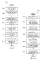
- FIG. 9 illustrates another example method 900 for performing a cutover from a legacy controller 102 to an advanced controller 102 ′.
- the method 900 can be used to perform a cutover from a legacy controller 102 to an advanced controller 102 ′ during a shutdown of part or all of a process system.
- an advanced controller is installed in a facility at step 902 .
- One or more control loops in a legacy controller are de-commissioned at step 904 . This could include, for example, personnel removing control loops from and deactivating a legacy controller 102 . There is no need in this case to maintain control of part or all of the process system, so the legacy controller 102 can be removed from operation before the advanced controller 102 ′ is brought online.
- Appropriate cables are rewired to the advanced controller at step 906 , the advanced controller is activated at step 908 , and one or more control loops are commissioned in the advanced controller at step 910 .
- the network state of the advanced controller is set to a suitable value in a junction gateway at step 912 .
- Supervisory control and APC functionality used in conjunction with the advanced controller are resumed at step 914 .
- a single legacy controller is being replaced during a partial or total shutdown of a process system.
- any number of legacy devices could be replaced during the shutdown.
- a subset of the legacy devices could be replaced during the shutdown, and one or more junction gateways 104 ′ can then be used to facilitate interactions with both legacy and advanced devices.
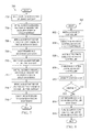
- FIG. 10 illustrates an example method 1000 that can be performed by the gateway 104 ′ to support interactions with legacy controllers 102 and/or advanced controllers 102 ′ during device migration or at other times.
- the gateway 104 ′ receives a request over a supervisory network at step 1002 .
- One or more controllers to receive the request are identified at step 1004 .
- the network status of each identified controller is identified at step 1006 .
- the request is transmitted (scattered) to the identified controller(s) at step 1008 .
- One or more responses to the request are received from the identified controller(s) at step 1010 .
- the responses can be in a format compliant with a legacy protocol.
- the gateway combines the response(s) into a suitable format (if necessary) at step 1012 and transmits the combined response(s) over the supervisory network at step 1014 .
- the junction gateway 104 ′ is able to effectively map multiple networks (the legacy network 103 and the advanced network 110 ) into the same logical representation expected by higher-level components. From the perspective of higher-level components, the gateway 104 ′ could appear as a standard gateway that supports the legacy protocol without any knowledge that the gateway 104 ′ also supports the use of an advanced protocol and is coupled to an advanced control network 110 .
- FIGS. 7 through 10 illustrate examples of methods for supporting migration from legacy devices to new devices
- various changes may be made to FIGS. 7 through 10 .
- each figure shows a series of steps
- various steps in each figure could overlap, occur in parallel, occur in a different order, or occur any number of times.
- the use of redundant gateways 104 ′ is optional, as is the use of protocol emulation over an advanced control network.
- various functions described above are implemented or supported by a computer program that is formed from computer readable program code and that is embodied in a computer readable medium.
- computer readable program code includes any type of computer code, including source code, object code, and executable code.
- computer readable medium includes any type of medium capable of being accessed by a computer, such as read only memory (ROM), random access memory (RAM), a hard disk drive, a compact disc (CD), a digital video disc (DVD), or any other type of memory.
- ROM read only memory
- RAM random access memory
- CD compact disc
- DVD digital video disc
- a “non-transitory” computer readable medium excludes wired, wireless, optical, or other communication links that transport transitory electrical or other signals.
- a non-transitory computer readable medium includes media where data can be permanently stored and media where data can be stored and later overwritten, such as a rewritable optical disc or an erasable memory device.
- application and “program” refer to one or more computer programs, software components, sets of instructions, procedures, functions, objects, classes, instances, related data, or a portion thereof adapted for implementation in a suitable computer code (including source code, object code, or executable code).
- program refers to one or more computer programs, software components, sets of instructions, procedures, functions, objects, classes, instances, related data, or a portion thereof adapted for implementation in a suitable computer code (including source code, object code, or executable code).
- communicate as well as derivatives thereof, encompasses both direct and indirect communication.
- the term “or” is inclusive, meaning and/or.
- phrases “associated with,” as well as derivatives thereof, may mean to include, be included within, interconnect with, contain, be contained within, connect to or with, couple to or with, be communicable with, cooperate with, interleave, juxtapose, be proximate to, be bound to or with, have, have a property of, have a relationship to or with, or the like.
- the phrase “at least one of,” when used with a list of items, means that different combinations of one or more of the listed items may be used, and only one item in the list may be needed. For example, “at least one of: A, B, and C” includes any of the following combinations: A, B, C, A and B, A and C, B and C, and A and B and C.
Abstract
An apparatus includes a first interface configured to communicate over a first industrial process control network using a first protocol. The apparatus also includes a second interface configured to communicate over a second industrial process control network using a second protocol. The apparatus further includes a third interface configured to communicate with at least one supervisory device over a third network. In addition, the apparatus includes at least one processing device configured to provide concurrent access for the at least one supervisory device to process control devices coupled to the first and second industrial process control networks during a migration of process control devices that use the first protocol to process control devices that use the second protocol.
Description
This disclosure relates generally to industrial process control and automation systems. More specifically, this disclosure relates to a gateway offering a logical model mapped to independent underlying networks.
Industrial process control and automation systems are often used to automate large and complex industrial processes. These types of control and automation systems routinely include sensors, actuators, and controllers. The controllers typically receive measurements from the sensors and generate control signals for the actuators.
If an existing legacy controller in a control and automation system is approaching its “end of life,” a new type of controller may need to be installed in the system. However, if the new type of controller is considerably different from the legacy controller being replaced, installing the new type of controller may require significant modifications to higher-level controllers, human-machine interfaces, or other components.
One prior approach to switching controllers involves performing a cutover of one or more legacy devices connected to an old network to replacement devices connected to a new network. This approach requires an industrial facility (or a portion thereof) to be shut down for a period of time. It may also require replacement of custom-created user interfaces and control applications used with the legacy devices. This can impose significant monetary losses on the facility's operators.
This disclosure provides a gateway offering a logical model mapped to independent underlying networks.
In a first embodiment, an apparatus includes a first interface configured to communicate over a first industrial process control network using a first protocol. The apparatus also includes a second interface configured to communicate over a second industrial process control network using a second protocol. The apparatus further includes a third interface configured to communicate with at least one supervisory device over a third network. In addition, the apparatus includes at least one processing device configured to provide concurrent access for the at least one supervisory device to process control devices coupled to the first and second industrial process control networks during a migration of process control devices that use the first protocol to process control devices that use the second protocol.
In a second embodiment, a method includes communicating over a first industrial process control network using a first protocol via a first interface. The method also includes communicating over a second industrial process control network using a second protocol via a second interface. The method further includes communicating with at least one supervisory device over a third network via a third interface. In addition, the method includes providing concurrent access for the at least one supervisory device to process control devices coupled to the first and second industrial process control networks during a migration of process control devices that use the first protocol to process control devices that use the second protocol.
In a third embodiment, a non-transitory computer readable medium embodies a computer program. The computer program includes computer readable program code for initiating communication over a first industrial process control network using a first protocol via a first interface. The computer program also includes computer readable program code for initiating communication over a second industrial process control network using a second protocol via a second interface. The computer program further includes computer readable program code for initiating communication with at least one supervisory device over a third network via a third interface. In addition, the computer program includes computer readable program code for providing concurrent access for the at least one supervisory device to process control devices coupled to the first and second industrial process control networks during a migration of process control devices that use the first protocol to process control devices that use the second protocol.
Other technical features may be readily apparent to one skilled in the art from the following figures, descriptions, and claims.
For a more complete understanding of this disclosure, reference is now made to the following description, taken in conjunction with the accompanying drawings, in which:
In the following description, a gateway supporting migration from legacy devices to new devices is described. A “legacy” device refers to a device being replaced by a more recent, more advanced, or other device. A “legacy” protocol refers to a protocol used by a legacy device, a “legacy” interface refers to an interface that supports the use of a legacy protocol, and a “legacy” network refers to a network that supports the use of a legacy protocol. A “new” or “advanced” device refers to a device that is replacing a legacy device. An “advanced” protocol refers to a protocol used by a new or advanced device, an “advanced” interface refers to an interface that supports the use of an advanced protocol, and an “advanced” network refers to a network that supports the use of an advanced protocol. Note that the terms “migration” and “replacement” (and their derivatives), when used with reference to a legacy device, include both a physical replacement of the legacy device with a new or advanced device and an upgrade of the legacy device to have one or more features of a new or advanced device.
Although the gateway is often described below as supporting the replacement of legacy process controllers with new or advanced process controllers in a process control and automation system, the gateway is not limited to use with just process controllers. Rather, the gateway can be used with any number(s) and type(s) of legacy devices being replaced with any number(s) and type(s) of new or advanced devices. Also, as a specific example of this functionality, the gateway is often described below as supporting the replacement of HIWAY-compliant devices with EXPERION-compliant devices, as well as the optional use of an emulated HIWAY protocol over a FAULT TOLERANT ETHERNET (FTE) network (HIWAY, EXPERION, and FAULT TOLERANT ETHERNET were developed by HONEYWELL INTERNATIONAL INC. or its subsidiaries). These specific protocols are examples only. The gateway disclosed in this patent document generally supports the replacement of any suitable legacy devices with any suitable new or advanced devices. Moreover, the gateway disclosed in this patent document could optionally support the emulation of any suitable legacy protocol over an Internet Protocol (IP)-based network or other advanced network.
The legacy controllers 102 communicate via a legacy network 103 with at least one legacy gateway 104. The legacy network 103 represents one or more communication paths that support interactions with the legacy controllers 102 using a legacy protocol. In some embodiments, the legacy network 103 could represent a coaxial network, such as a HIWAY network. However, the legacy network 103 could represent any other suitable legacy industrial process control network.
The legacy controllers 102 communicate with higher-level devices and systems via the legacy gateway(s) 104. In this example, each legacy gateway 104 facilitates communication between the legacy network 103 and a supervisory network 106, such as a local control network (LCN). Each legacy gateway 104 includes any suitable structure facilitating communication with one or more legacy devices via a supervisory network. The supervisory network 106 represents a network facilitating communication among higher-level process control and automation devices and systems.
In particular embodiments, the legacy controllers 102 represent HIWAY controllers and PROCESS INTERFACE UNIT (PIU) devices, such as TDC2000 devices from HONEYWELL INTERNATIONAL INC. These types of devices routinely communicate over a “data hiway,” which uses the HIWAY protocol supported by the legacy gateway 104. The legacy gateway 104 converts between that protocol and the protocol used by the supervisory network 106.
The system 100 also includes one or more advanced controllers 108 that communicate over an advanced control network 110. The advanced controllers 108 represent controllers that are newer, more technologically advanced, or more feature-rich that the legacy controllers 102. Similarly, the control network 110 could represent a newer, more technologically advanced, or more feature-rich network for transporting control information, such as an IP-based network. In particular embodiments, the advanced controllers 108 could represent C300 controllers from HONEYWELL INTERNATIONAL INC., and the control network 110 could represent an FTE or other redundant IP-based network.
Various other components in the system 100 support a wide range of process control and automation-related functions. For example, one or more operator consoles 112 can be used by operators to interact with the system 100. At least one supervisory controller 114 and at least one server 116 provide higher-level control in the system 100. For instance, the supervisory controller 114 and/or server 116 could perform more advanced planning or scheduling operations, execute higher-level control strategies, or perform other functions. At least one application processing platform 118 can be used to automate various procedures in the system 100. At least one historian 120 can be used to collect and store data associated with operation of the system 100 over time. Various ones of these components are often said to reside within or form a part of a “Level 2” supervisory network in a control and automation system.
Each operator console 112 includes any suitable structure for facilitating operator interactions, such as an EXPERION STATION TPS from HONEYWELL INTERNATIONAL INC. Each controller 114 includes any suitable structure for providing supervisory control, such as an APPLICATION CONTROL ENVIRONMENT-TPS (ACE-T) node from HONEYWELL INTERNATIONAL INC. Each server 116 represents any suitable computing device, such as an EXPERION SERVER TPS from HONEYWELL INTERNATIONAL INC. (or a redundant pair of such servers). Each application processing platform 118 includes any suitable structure for executing automated procedures, such as an APPLICATION MODULE (AM) from HONEYWELL INTERNATIONAL INC. Each historian 120 includes any suitable structure for storing data, such as a HISTORY MODULE (HM) from HONEYWELL INTERNATIONAL INC.
As shown in FIG. 1 , the legacy controllers 102 are being replaced with advanced controllers 102′. This could occur, for instance, when the legacy controllers 102 have reached their “end of life” and are no longer supported by a vendor or manufacturer. Moreover, the legacy gateway 104 is being replaced with a junction gateway 104′, which (as described below) supports the migration from the legacy controllers 102 to the advanced controllers 102′.
One conventional approach to replacing legacy controllers is “rip and replace,” where a facility or portion thereof is simply shut down and the legacy controllers are replaced with new controllers. However, this approach requires facility down time and associated monetary losses. Moreover, legacy controllers 102 are often managed using higher-level components, such as the application processing platform 118 that typically implements a large number of procedures involving the legacy controllers 102. As a result, simply replacing the legacy controllers 102 would require large amounts of work to update the procedures executed by the application processing platform 118 or to migrate those procedures to a supervisory controller 114. In addition, operators often interact with legacy controllers 102 via interfaces provided at the operator consoles 112. The “rip and replace” technique typically requires updating or replacing the interfaces supported by the operator consoles 112 and may actually require replacement of the entire supervisory network 106 and all connected devices.
In accordance with this disclosure, the junction gateway 104′ supports an improved transition between the use of legacy controllers 102 and the use of advanced controllers 102′. As described in more detail below, the junction gateway 104′ can be connected to both the legacy controllers 102 (via the legacy network 103) and the advanced controllers 102′ (via the control network 110). This allows the legacy controllers 102 to remain online and operational while the advanced controllers 102′ are installed, commissioned, and brought online. Once the advanced controllers 102′ are ready for operation, control of a process system can be transferred from the legacy controllers 102 to the advanced controllers 102′. This helps to avoid shutting down part or all of a process system and allows operators to verify that the advanced controllers 102′ are operating correctly prior to placing them into active control operation.
The junction gateway 104′ may also emulate or otherwise support at least one legacy protocol over the control network 110. For example, the junction gateway 104′ could be configured to emulate the HIWAY protocol used by legacy controllers 102 over an FTE or other advanced control network 110. This allows some higher-level devices (such as the components 118-120) to interact with the advanced controllers 102′ via the gateway 104′ as if the advanced controllers 102′ support the legacy protocol(s) used by the legacy controllers 102. This also allows other higher-level devices (such as the components 112-116) to interact with the advanced controllers 102′ via the network 110 without using the gateway 104′. As a particular example, the junction gateway 104′ can receive requests from higher-level devices, scatter the requests to the advanced controllers 102′, gather responses that are in a format compliant with a legacy protocol, and submit compiled responses to the higher-level devices.
Using these techniques, the junction gateway 104′ allows legacy controllers 102 to be replaced with advanced controllers 102′ without requiring a shutdown of part or all of an industrial process system. Moreover, the junction gateway 104′ allows the advanced controllers 102′ to be installed, commissioned, and tested without interfering with the control operations of the legacy controllers 102, allowing the advanced controllers 102′ to be brought online without interrupting the control of the process system. Further, the junction gateway 104′ could allow the advanced controllers 102′ to be used with both higher-level components that still use the legacy protocol and higher-level components that use an advanced protocol. This could reduce or avoid the need to update or migrate procedures executed by the application processing platform 118 and the interfaces supported by the operator consoles 112.
In addition, using these techniques, it is possible to “decouple” the replacement of the legacy controllers 102 from the replacement of components such as Level 2 devices or systems. As a result, the Level 2 devices or systems can be replaced at the same time as or at a different time than the legacy controllers 102. For example, most or all Level 2 devices or systems can continue operations with the advanced controllers 102′ and can be replaced as fast or as slow as desired. This can help to reduce the cost of replacing the legacy controllers 102 and allow expenses to be distributed over a greater length of time.
Example details regarding the junction gateway 104′ are provided below. Note that the system 100 could include any number of junction gateways 104′ to support the migration of any number of legacy controllers 102 or other legacy devices to advanced controllers 102′ or other advanced devices.
Although FIG. 1 illustrates one example of a migration from legacy devices to new devices in an industrial process control and automation system 100, various changes may be made to FIG. 1 . For example, various components in FIG. 1 could be combined, further subdivided, moved, or omitted and additional components could be added according to particular needs. Also, the system 100 could include any number of each component shown in FIG. 1 . Control and automation systems come in a wide variety of configurations, and FIG. 1 does not limit the scope of this disclosure to any particular configuration. In addition, the components 112-120 shown in FIG. 1 are only examples of the types of higher-level components that might be present in a system and interact with legacy controllers 102 and advanced controllers 102′. Other or additional higher-level components could also be used.
As shown in FIG. 2 , the gateway 104′ includes a housing 202. The housing 202 generally denotes a structure that protects, encases, or holds other components of the gateway 104′. The housing 202 includes any suitable structure in which other components of a gateway can be placed. The housing 202 could also be formed from any suitable material(s) and in any suitable manner. In particular embodiments, the housing 202 includes a chassis into which printed circuit board (PCB) cards can be inserted and coupled to a backplane or other structure.
The gateway 104′ also includes three interfaces 204-208. The interface 204 supports communication over a supervisory network 106. For example, the interface 204 can receive data from and transmit data to various components 112-120 coupled to the supervisory network 106 using at least one standard or proprietary protocol.
The interface 206 supports communication over a legacy communication link 210, which could be coupled to the legacy network 103. The legacy communication link 210 represents a communication link used to communicate with one or more legacy controllers 102. In particular embodiments, the legacy communication link 210 supports communication with HIWAY controllers and PIU devices.
The interface 208 supports communication over an advanced communication link 212. The communication link 212 could represent a communication link used to communicate over the advanced control network 110, and those communications can optionally be made via an emulation of the legacy protocol used by legacy controllers 102 (although this is not necessarily required). In particular embodiments, the communication link 212 supports communication using an emulated HIWAY protocol over an FTE or other IP-based network.
Among other things, the gateway 104′ can translate between the protocols used by the supervisory network 106, the control network 110, and the legacy network 103. This allows the legacy controllers 102 to be used while the advanced controllers 102′ are being installed, commissioned, and brought online. This can optionally allow communications to and from the advanced controllers 102′ using the emulated protocol, so higher-level devices that still use or rely on the legacy protocol can continue to interact with the advanced controllers 102′.
The gateway 104′ also includes at least one processing device 214 and at least one memory 216. The processing device 214 controls the overall operation of the gateway 104′. For example, the processing device 214 could control the operations of the interfaces 204-208 to thereby control the transmission and reception of data by the gateway 104′. The processing device 214 could also support any translations or other operations needed to support the flow of data between different interfaces 204-208. For instance, the processing device 214 can determine how specific controllers are to be contacted and initiate communications to and from the controllers via the appropriate interfaces 206-208. As a particular example, the processing device 214 can support the “scattering/gathering” of requests and responses, meaning the processing device 214 can transmit (scatter) requests to one or multiple devices (legacy and/or advanced devices), collect (gather) responses to the requests, and combine the responses into a suitable format for transmission over the supervisory network 106.
The processing device 214 includes any suitable structure for performing or controlling operations of a gateway, such as one or more processing or computing devices. As particular examples, the processing device 214 could include at least one microprocessor, microcontroller, digital signal processor, field programmable gate array, application specific integrated circuit, or discrete logic device.
The memory 216 stores instructions or data used, generated, or collected by the gateway 104′. For example, the memory 216 could store software or firmware instructions executed by the processing device 214. The memory 216 could also store data received via one interface 204-208 that is to be transmitted over another interface 204-208. The memory 216 includes any suitable volatile and/or non-volatile storage and retrieval device(s), such as at least one random access memory and at least one Flash or other read-only memory.
In particular embodiments, the interface 204 could represent a K4LCN interface card from HONEYWELL INTERNATIONAL INC., with modifications made to the firmware of the card to support appropriate interactions over the supervisory network 106. The processing device 214 and the memory 216 could reside on the K4LCN interface card. Also, in particular embodiments, the interface 206 could represent a DATA HIGHWAY INTERFACE (DHI) card from HONEYWELL INTERNATIONAL INC. Further, in particular embodiments, the interface 208 could represent an interface card with firmware designed to emulate the HIWAY protocol over an FTE or other IP-based network, which could be known as an ENHANCED HIWAY BRIDGE INTERFACE (EHBI).
A bus 218 supports communications between other components of the gateway 104′, such as the interfaces 204-208, the processing device 214, and the memory 216. The bus 218 represents any suitable communication path(s) for transporting data or other signals in a gateway.
By providing both the interfaces 206-208, the gateway 104′ is able to support communications over both a legacy network 103 and an advanced control network 110. Moreover, by using the single interface 204, the gateway 104′ is able to present itself as a single logical HIWAY device (or a device compliant with another legacy protocol) on the supervisory network 106. Thus, the gateway 104′ enables communications with both legacy controllers 102 and advanced controllers 102′ while still appearing as an appropriate device on the supervisory network 106 to higher-level components.
In FIG. 3 , an LCN data entity builder (DEB) 302 represents an application used to configure and manage legacy controllers 102, such as to perform engineering configurations on the legacy controllers. Components 304-314 represent subsystems of the system 100 that can interact with the gateway 104′ over the supervisory network 106. Applications 304 denote applications that could be executed on an APPLICATION MODULE or other application processing platform 118. Native windows 306, global user station (GUS) displays 308, HMIWEB displays 310, and notification displays 312 represent applications that present displays to operators via different types of operator consoles 112. The displays 306-310 can be used by operators to make changes to certain variables associated with a process system, and the display 312 can be used by operators to acknowledge or respond to various notifications. Applications 314 denote applications that could be executed on an ACE-T node or other supervisory controller 114.
A control builder 316 can be used to configure and manage the advanced controllers 102′. The control builder 316 can be used, for example, by one or more applications engineers to translate HIWAY GATEWAY (HG) control points into suitable control execution environment (CEE) emulations. The control builder 316 can also be used by one or more systems engineers to configure the interface 208 in the gateway 104′ and the advanced controllers 102′.
As shown in FIG. 3 , different types of information can be exchanged between the components of FIG. 3 over different types of networks. For example, the gateway 104′ can exchange HIWAY messages with the legacy controllers 102 over the legacy network 103. The gateway 104′ can also exchange emulated HIWAY messages with the advanced controllers 102′ over the network 110. The gateway 104′ can further exchange gateway parameters, as well as event initiated processing (EIP) events, with the components 304-312 over the supervisory network 106. In addition, the gateway 104′ can exchange process alarms with the notification displays 312 and configuration data with the control builder 316 over the control network 110. Moreover, the advanced controllers 102′ can communicate events to the notification displays 312 and exchange configuration data with the control builder 316 over the control network 110.
As described above, one use of the gateway 104′ is to facilitate migration from the legacy controllers 102 to the advanced controllers 102′ without requiring a shutdown of part or all of an industrial process system. This can be accomplished using, among other things, concurrent access via the gateway 104′ to the legacy controllers 102 and the advanced controllers 102′. Moreover, the decoupling of the migration of Level 1 and Level 2 devices can be supported using, among other things, the emulation of a legacy protocol (such as a HIWAY protocol) by the gateway 104′ so that higher-level devices can continue operating under the assumption that the advanced controllers 102′ support the legacy protocol. As a result, Level 1 legacy devices (such as legacy controllers 102) can be migrated to advanced devices (such as advanced controllers 102′) without requiring much if any modifications to Level 2 components. The Level 2 components could be migrated at the same time as the Level 1 components, or any desired length(s) of time could elapse until the Level 2 components are migrated.
Moreover, the concurrent access to the legacy controllers 102 and the advanced controllers 102′ supports both fast and prolonged cutovers of the controllers. The use of the gateway 104′ allows the legacy controllers 102 to be used to control a process system while the advanced controllers 102′ are installed, commissioned, and tested. This can occur over a short period of time or a prolonged period of time depending on various factors. Once operation of the advanced controllers 102′ is determined to be satisfactory, the advanced controllers 102′ can be placed into control operation while the legacy controllers 102 are placed into standby mode. If the advanced controllers 102′ perform as expected, the legacy controllers 102 can be decommissioned and removed from the system. If the advanced controllers 102′ do not perform as expected, the legacy controllers 102 can be brought back into active operation.
In addition, it is possible for the migration of legacy controllers 102 to advanced controllers 102′ to occur incrementally, such as one legacy controller 102 or a subset of legacy controllers 102 at a time. Thus, there may be times when both legacy controllers 102 and advanced controllers 102′ are performing control actions in the system 100. The gateway 104′ supports such incremental migration by helping to ensure that communications with both types of controllers can occur concurrently.
In this particular embodiment, the gateway 104′ supports the use of an emulated HIWAY protocol over an FTE control network 110. This can be done, for example, to communicate with the C300 advanced controllers 102′ via the control network 110. In this approach, the gateway 104′ emulates the use of the HIWAY protocol, but data is transported over the network 110 using IP-based data packets.
As noted above, the gateway 104′ supports the “scattering” of requests and the “gathering” of responses. For example, the processing device 214 could receive a request via the interface 204 and identify the controller(s) to receive the request. The processing device 214 could then “scatter” the request to one or more controllers via one or more of the interfaces 206-208. The exact interface(s) 206-208 used could depend on which controller(s) need to receive the request and what the “box network state” is of the controller(s) to receive the request. In some embodiments, the box network state could indicate that a controller is either a HIWAY device (for a legacy controller) or an ETHERNET device (for an advanced controller). If sent over the legacy network 103, the request could follow the standard legacy protocol. If sent over the control network 110, the processing device 214 can optionally emulate the legacy protocol using IP-based messages. In either case, the appropriate controller(s) 102, 102′ can receive the request and respond, such as via a standard HIWAY response or via an IP-based response containing the contents of a standard HIWAY response. The processing device 214 can then “gather” the one or more responses from the appropriate controller(s) and place the responses into a suitable format for communication over the supervisory network 106.
The second protocol 404 is used by various supervisory devices. A “node” refers to a particular device, and a “point” and a “parameter” (often referred to as “point.parameter”) refer to a particular value in the identified device. The third protocol 406 is used by EXPERION devices. A “platform” refers to a particular device, and a “module,” a “block,” and a “parameter” refer to a particular value in the identified device.
Note that there are a wide variety of ways in which these protocols can be used. For example, in a first approach, emulations of HIWAY algorithms or other legacy algorithms can be created in an advanced controller 110 that present data and messaging consistent with original HIWAY or other legacy objects. In a second approach, HIWAY or other legacy algorithms can be ported to an advanced controller 110, and the re-hosted algorithms can present their original data and messages just as they did on the legacy network. In a third approach, translation functionality can be supported by a junction gateway 104′ so that the gateway 104′ can receive data and messages native to the advanced controller 110 and present the data and messages in a format expected on the supervisory network 106. In a fourth approach, a junction gateway 104′ is used over a controller whose migration includes changing its network interface from the legacy network to the advanced network without changing the controller or its algorithms at all. In this fourth approach, an application protocol used by the legacy controller is unchanged and can be wrapped by the protocol used in the advanced network.
Although FIGS. 2 through 4 illustrate one example of a gateway 104′ supporting migration from legacy devices to new devices and related details, various changes may be made to FIGS. 2 through 4 . For example, the functional division shown in FIG. 2 is for illustration only. Various components in FIG. 2 could be combined, further subdivided, moved, or omitted and additional components could be added according to particular needs. As a particular example, the processing device 214 and memory 216 could be placed onto the same PCB card or other substrate as one, some, or all interfaces 204-208. Also, the specific protocols and use cases shown in FIGS. 3 and 4 are examples only. The gateway 104′ could support the use of other or additional protocols, and the gateway 104′ could be used in any other suitable manner.
In FIG. 5 , an operator has elected to show command options for the box numbered “12,” which causes the gateway 104′ to present a list 506 of commands in the interface. Controls 508 in the interface 500 can be used in various ways in the interface 500. In this case, the controls 508 can be used to invoke particular commands from the list 506 and to control the display of information in the interface 500.
In FIG. 6 , a graphical user interface 600 can be used during replacement of a legacy controller 102 with an advanced controller 102′. As shown in FIG. 6 , the interface 600 includes a listing 602 of control points associated with the legacy controller 102. Each control point is associated with a process variable and various values associated with the process variable. The interface 600 also includes a listing 604 of emulated control points associated with the advanced controller 102′.
The interface 600 can be presented to an operator during the time that wires and other data connections are being moved from the legacy controller 102 to the advanced controller 102′. As can be seen in FIG. 6 , the values in the listing 604 are identical or substantially identical to the values in the listing 602. This indicates that the advanced controller 102′ is receiving the same data and operating to produce substantially the same outputs that the legacy controller 102 being replaced was receiving and producing.
Although FIGS. 5 and 6 illustrate examples of graphical user interfaces supporting migration from legacy devices to new devices, various changes may be made to FIGS. 5 and 6 . For example, these interfaces are merely meant to illustrate different types of interfaces that could be supported by a gateway 104′. Any other or additional interfaces could also be used.
As shown in FIG. 7 , the backup partner of a legacy gateway is shut down at step 702. This could include, for example, personnel powering down the secondary legacy gateway 104, while the primary legacy gateway 104 can continue operating. Needed hardware/software/firmware is installed on the backup partner of the legacy gateway at step 704. This could include, for example, personnel installing a PCB card that supports the interface 208, which allows communication over an advanced network. This could also optionally include personnel programming the interface 208 to support an emulated protocol over the advanced network. This could further include personnel updating the processing device 214 to perform the desired operations of the gateway 104′. Once this is completed, the backup partner of the legacy gateway is brought back online as a first junction gateway at step 706. This could include, for example, bringing the upgraded gateway online as a first junction gateway 104′ that is operating in the secondary role.
The primary and secondary gateways swap roles at step 708. That is, a second legacy gateway 104 can begin operating in the secondary role, while the first junction gateway 104′ can begin operating in the primary role. This could occur at any suitable time, such as after operation of the first junction gateway 104′ is verified. At this point, the same general steps 710-714 can be used to convert the backup partner of the first junction gateway 104′ into a second junction gateway 104′. At the end of step 714, there are two junction gateways 104′ operating in the system 100, one in a primary mode and one in a secondary mode. Interfaces to an advanced network in the gateways are configured at step 716. This could include, for example, personnel configuring EXPERION platform modules in the interfaces 208 of the junction gateways 104′.
During these steps, there may be a continuous communication path from the supervisory network 106 through at least one gateway 104, 104′ to the legacy controllers 102. As a result, there may be no loss of communication or control during the migration from the legacy gateways 104 to the junction gateways 104′. Once the junction gateways 104′ are available in the system 100 (however obtained), the replacement of legacy devices with advanced devices can occur as described below. Note that any length of time could elapse between (i) migration of the legacy gateways 104 to the junction gateways 104′ and (ii) migration of the legacy controllers 102 to the advanced controllers 102′. Also note that migration of the legacy devices to the advanced devices could occur using a single junction gateway 104′.
As shown in FIG. 8 , an advanced controller is installed in a facility at step 802. Supervisory control and advanced process control (APC) functionality used in conjunction with a legacy controller is deactivated at step 804. This could include, for example, personnel deactivating these functions in higher-level components of a control and automation system 100, such as in one or more Level 2 components.
Appropriate cables are rewired to the advanced controller at step 806, and a control loop is commissioned in the advanced controller at step 808. This could include, for example, personnel decoupling wires or other communication paths previously used to communicate with industrial field devices from the legacy controller 102 and coupling the wires or other communication paths to the advanced controller 102′. The cables rewired here could represent the cables needed for the current control loop. This could also include personnel creating an appropriate control loop in the advanced controller 102′ for controlling one or more aspects of the industrial process system previously controlled by the legacy controller 102. As part of this, personnel could set certain control modes or HG points to manual mode. In some embodiments, this could further include personnel loading emulation logic into the advanced controller 102′ if the advanced controller 102′ is emulating a legacy protocol. As noted above, however, protocol emulation could be supported by the junction gateway 104′ or in other ways. Once the advanced controller's output is balanced with the process, the current control loop can be placed into operation at step 810.
A decision is made whether to continue loading control loops at step 812. If so, the process returns to step 806. If not, the network state of the advanced controller is set to a suitable value in a junction gateway at step 814. This could include, for example, an application engineer changing the box network state previously associated with the legacy controller 102 to a new value associated with the advanced controller 102′. Supervisory control and APC functionality used in conjunction with the advanced controller are re-activated at step 816.
Note that during the cutover from the legacy controller 102 to the advanced controller 102′, an interface such as that shown in FIG. 6 could be presented to an operator. This interface 600 allows the operator to see if the advanced controller 102′ is receiving the same data and operating to produce substantially the same outputs that the legacy controller 102 being replaced was receiving and producing. Also note that while FIG. 8 assumes the legacy controller 102 is disconnected from the field devices when cables are rewired to the advanced controller 102′, this need not be the case. For instance, the advanced controller 102′ could be wired in parallel to the field devices with the legacy controller 102. The advanced controller 102′ could be configured to receive data from certain field devices and identify desired control signals for other field devices, but the advanced controller 102′ could be disabled from outputting those control signals until operation of the advanced controller 102′ is approved. At that point, the legacy controller 102 can be disabled from outputting control signals while the advanced controller 102′ is outputting control signals.
As shown in FIG. 9 , an advanced controller is installed in a facility at step 902. One or more control loops in a legacy controller are de-commissioned at step 904. This could include, for example, personnel removing control loops from and deactivating a legacy controller 102. There is no need in this case to maintain control of part or all of the process system, so the legacy controller 102 can be removed from operation before the advanced controller 102′ is brought online.
Appropriate cables are rewired to the advanced controller at step 906, the advanced controller is activated at step 908, and one or more control loops are commissioned in the advanced controller at step 910. This could include, for example, personnel decoupling wires or other communication paths previously used to communicate with industrial field devices from the legacy controller 102 and coupling the wires or other communication paths to the advanced controller 102′. This could also include personnel creating appropriate control loops in the advanced controller 102′ for controlling all of the aspects of the industrial process system previously controlled by the legacy controller 102.
The network state of the advanced controller is set to a suitable value in a junction gateway at step 912. This could include, for example, an application engineer changing the box network state previously associated with the legacy controller 102 to a new value associated with the advanced controller 102′. Supervisory control and APC functionality used in conjunction with the advanced controller are resumed at step 914.
Note that in FIG. 9 , a single legacy controller is being replaced during a partial or total shutdown of a process system. However, any number of legacy devices could be replaced during the shutdown. Moreover, there is no requirement that all legacy devices be replaced during the shutdown. For instance, a subset of the legacy devices could be replaced during the shutdown, and one or more junction gateways 104′ can then be used to facilitate interactions with both legacy and advanced devices.
One or more controllers to receive the request are identified at step 1004. This could include, for example, the processing device 214 using the contents of the received request to identify which controller or controllers 102, 102′ are to receive the request. The network status of each identified controller is identified at step 1006. This could include, for example, the processing device 214 using the box network status of each identified controller to determine whether that identified controller is configured to communicate over a legacy network or an advanced control network. The request is transmitted (scattered) to the identified controller(s) at step 1008. This could include, for example, the processing device 214 initiating transmission of the request to any identified legacy controllers 102 via the interface 206 and transmission of the request to any identified advanced controllers 102′ via the interface 208.
One or more responses to the request are received from the identified controller(s) at step 1010. This could include, for example, the processing device 214 receiving a response from any identified legacy controllers 102 via the interface 206 and receiving a response from any identified advanced controllers 102′ via the interface 208. The responses can be in a format compliant with a legacy protocol. The gateway combines the response(s) into a suitable format (if necessary) at step 1012 and transmits the combined response(s) over the supervisory network at step 1014. This could include, for example, the processing device 214 combining any responses into a format compliant with the HIWAY protocol.
In this way, the junction gateway 104′ is able to effectively map multiple networks (the legacy network 103 and the advanced network 110) into the same logical representation expected by higher-level components. From the perspective of higher-level components, the gateway 104′ could appear as a standard gateway that supports the legacy protocol without any knowledge that the gateway 104′ also supports the use of an advanced protocol and is coupled to an advanced control network 110.
Although FIGS. 7 through 10 illustrate examples of methods for supporting migration from legacy devices to new devices, various changes may be made to FIGS. 7 through 10 . For example, while each figure shows a series of steps, various steps in each figure could overlap, occur in parallel, occur in a different order, or occur any number of times. Moreover, the use of redundant gateways 104′ is optional, as is the use of protocol emulation over an advanced control network.
In some embodiments, various functions described above are implemented or supported by a computer program that is formed from computer readable program code and that is embodied in a computer readable medium. The phrase “computer readable program code” includes any type of computer code, including source code, object code, and executable code. The phrase “computer readable medium” includes any type of medium capable of being accessed by a computer, such as read only memory (ROM), random access memory (RAM), a hard disk drive, a compact disc (CD), a digital video disc (DVD), or any other type of memory. A “non-transitory” computer readable medium excludes wired, wireless, optical, or other communication links that transport transitory electrical or other signals. A non-transitory computer readable medium includes media where data can be permanently stored and media where data can be stored and later overwritten, such as a rewritable optical disc or an erasable memory device.
It may be advantageous to set forth definitions of certain words and phrases used throughout this patent document. The terms “application” and “program” refer to one or more computer programs, software components, sets of instructions, procedures, functions, objects, classes, instances, related data, or a portion thereof adapted for implementation in a suitable computer code (including source code, object code, or executable code). The term “communicate,” as well as derivatives thereof, encompasses both direct and indirect communication. The terms “include” and “comprise,” as well as derivatives thereof, mean inclusion without limitation. The term “or” is inclusive, meaning and/or. The phrase “associated with,” as well as derivatives thereof, may mean to include, be included within, interconnect with, contain, be contained within, connect to or with, couple to or with, be communicable with, cooperate with, interleave, juxtapose, be proximate to, be bound to or with, have, have a property of, have a relationship to or with, or the like. The phrase “at least one of,” when used with a list of items, means that different combinations of one or more of the listed items may be used, and only one item in the list may be needed. For example, “at least one of: A, B, and C” includes any of the following combinations: A, B, C, A and B, A and C, B and C, and A and B and C.
While this disclosure has described certain embodiments and generally associated methods, alterations and permutations of these embodiments and methods will be apparent to those skilled in the art. Accordingly, the above description of example embodiments does not define or constrain this disclosure. Other changes, substitutions, and alterations are also possible without departing from the spirit and scope of this disclosure, as defined by the following claims.
Claims (20)
1. An apparatus comprising:
a gateway including:
a first interface configured to communicate over a first industrial process control network using a first protocol;
a second interface configured to communicate over a second industrial process control network using a second protocol;
a third interface configured to communicate with at least one supervisory device over a third network; and
at least one processing device configured to provide concurrent access for the at least one supervisory device to process control devices coupled to the first and second industrial process control networks during a migration of process control devices that use the first protocol to process control devices that use the second protocol.
2. The apparatus of claim 1 , wherein the second interface is configured to emulate the first protocol over the second industrial process control network.
3. The apparatus of claim 1 , wherein the at least one processing device is further configured to make all of the process control devices coupled to the first and second industrial process control networks appear to be devices coupled only to the first industrial process control network.
4. The apparatus of claim 1 , wherein the at least one processing device is further configured to provide substantially continuous access by the at least one supervisory device to at least one of the process control devices.
5. The apparatus of claim 4 , wherein the at least one processing device is configured to provide the substantially continuous access by using a network state to identify whether requests from the at least one supervisory device are transmitted to a specified process control device via the first interface or via the second interface.
6. The apparatus of claim 5 , wherein the at least one processing device is configured to track multiple network states as multiple process control devices coupled to the first industrial process control network are migrated to multiple process control devices coupled to the second industrial process control network.
7. The apparatus of claim 1 , wherein:
the first interface is configured to communicate over a coaxial network; and
the second interface is configured to communicate over a redundant Ethernet network.
8. A method comprising:
communicating over a first industrial process control network using a first protocol via a first interface of a gateway;
communicating over a second industrial process control network using a second protocol via a second interface of the gateway;
communicating with at least one supervisory device over a third network via a third interface of the gateway; and
providing concurrent access, by the gateway, for the at least one supervisory device to process control devices coupled to the first and second industrial process control networks during a migration of process control devices that use the first protocol to process control devices that use the second protocol.
9. The method of claim 8 , wherein the second interface emulates the first protocol over the second industrial process control network.
10. The method of claim 8 , further comprising:
making all of the process control devices coupled to the first and second industrial process control networks appear to be devices coupled only to the first industrial process control network.
11. The method of claim 8 , further comprising:
providing substantially continuous access by the at least one supervisory device to at least one of the process control devices.
12. The method of claim 11 , wherein providing the substantially continuous access comprises using a network state to identify whether requests from the at least one supervisory device are transmitted to a specified process control device via the first interface or via the second interface.
13. The method of claim 12 , further comprising:
tracking multiple network states as multiple process control devices coupled to the first industrial process control network are migrated to multiple process control devices coupled to the second industrial process control network.
14. The method of claim 13 , wherein:
the process control devices coupled to the first industrial process control network comprise legacy process controllers controlling one or more aspects of an industrial process system; and
the process control devices coupled to the second industrial process control network comprise advanced process controllers controlling the one or more aspects of the industrial process system.
15. The method of claim 8 , wherein:
the first and second industrial process control networks comprise Level 1 networks; and
the third network comprises a Level 2 network.
16. A non-transitory computer readable medium containing a computer program, the computer program comprising computer readable program code that when executed causes at least one processing device to:
initiate communication over a first industrial process control network using a first protocol via a first interface of a gateway;
initiate communication over a second industrial process control network using a second protocol via a second interface of the gateway;
initiate communication with at least one supervisory device over a third network via a third interface of the gateway; and
provide concurrent access, by the gateway, for the at least one supervisory device to process control devices coupled to the first and second industrial process control networks during a migration of process control devices that use the first protocol to process control devices that use the second protocol.
17. The non-transitory computer readable medium of claim 16 , wherein the computer program further comprises computer readable program code that when executed causes the at least one processing device to make all of the process control devices coupled to the first and second industrial process control networks appear to be devices coupled only to the first industrial process control network.
18. The non-transitory computer readable medium of claim 16 , wherein the computer program further comprises computer readable program code that when executed causes the at least one processing device to provide substantially continuous access by the at least one supervisory device to at least one of the process control devices.
19. The non-transitory computer readable medium of claim 18 , wherein the computer readable program code that when executed causes the at least one processing device to provide the substantially continuous access comprises:
computer readable program code that when executed causes at least one processing device to use a network state to identify whether requests from the at least one supervisory device are transmitted to a specified process control device via the first interface or via the second interface.
20. The non-transitory computer readable medium of claim 19 , wherein the computer program comprises computer readable program code that when executed causes the at least one processing device to track multiple network states as multiple process control devices coupled to the first industrial process control network are replaced with multiple process control devices coupled to the second industrial process control network.
Priority Applications (6)
| Application Number | Priority Date | Filing Date | Title |
|---|---|---|---|
| US14/269,903 US9720404B2 (en) | 2014-05-05 | 2014-05-05 | Gateway offering logical model mapped to independent underlying networks |
| PCT/US2015/026058 WO2015171281A1 (en) | 2014-05-05 | 2015-04-16 | Gateway offering logical model mapped to independent underlying networks |
| CN201580022972.3A CN106464575B (en) | 2014-05-05 | 2015-04-16 | Gateway providing logical model mapping to independent underlying network |
| AU2015256526A AU2015256526B2 (en) | 2014-05-05 | 2015-04-16 | Gateway offering logical model mapped to independent underlying networks |
| JP2016566949A JP6527173B2 (en) | 2014-05-05 | 2015-04-16 | Gateway providing logical model mapped to independent underlying network |
| EP15789317.3A EP3140963B1 (en) | 2014-05-05 | 2015-04-16 | Gateway offering logical model mapped to independent underlying networks |
Applications Claiming Priority (1)
| Application Number | Priority Date | Filing Date | Title |
|---|---|---|---|
| US14/269,903 US9720404B2 (en) | 2014-05-05 | 2014-05-05 | Gateway offering logical model mapped to independent underlying networks |
Publications (2)
| Publication Number | Publication Date |
|---|---|
| US20150316923A1 US20150316923A1 (en) | 2015-11-05 |
| US9720404B2 true US9720404B2 (en) | 2017-08-01 |
Family
ID=54355195
Family Applications (1)
| Application Number | Title | Priority Date | Filing Date |
|---|---|---|---|
| US14/269,903 Active 2036-02-10 US9720404B2 (en) | 2014-05-05 | 2014-05-05 | Gateway offering logical model mapped to independent underlying networks |
Country Status (6)
| Country | Link |
|---|---|
| US (1) | US9720404B2 (en) |
| EP (1) | EP3140963B1 (en) |
| JP (1) | JP6527173B2 (en) |
| CN (1) | CN106464575B (en) |
| AU (1) | AU2015256526B2 (en) |
| WO (1) | WO2015171281A1 (en) |
Families Citing this family (8)
| Publication number | Priority date | Publication date | Assignee | Title |
|---|---|---|---|---|
| US20160103431A1 (en) * | 2014-10-14 | 2016-04-14 | Honeywell International, Inc. | System and method for point by point hot cutover of controllers and ios |
| US20180129191A1 (en) * | 2016-11-04 | 2018-05-10 | Rockwell Automation Technologies, Inc. | Industrial automation system machine analytics for a connected enterprise |
| US10401816B2 (en) * | 2017-07-20 | 2019-09-03 | Honeywell International Inc. | Legacy control functions in newgen controllers alongside newgen control functions |
| US10878690B2 (en) | 2017-11-02 | 2020-12-29 | Honeywell International Inc. | Unified status and alarm management for operations, monitoring, and maintenance of legacy and modern control systems from common user interface |
| US11237550B2 (en) | 2018-03-28 | 2022-02-01 | Honeywell International Inc. | Ultrasonic flow meter prognostics with near real-time condition based uncertainty analysis |
| US10824810B2 (en) | 2018-06-07 | 2020-11-03 | Honeywell International Inc. | System and method for identifying correlated operator action events based on text analytics of operator actions |
| US11750715B2 (en) * | 2020-07-17 | 2023-09-05 | Rockwell Automation Technologies, Inc. | Industrial automation broker device |
| EP4198659A1 (en) * | 2021-12-14 | 2023-06-21 | Atos Worldgrid | Control system and method with high availability for an industrial process |
Citations (119)
| Publication number | Priority date | Publication date | Assignee | Title |
|---|---|---|---|---|
| US4679189A (en) | 1985-11-27 | 1987-07-07 | American Telephone And Telegraph Company | Alternate routing arrangement |
| DE4134207C1 (en) | 1991-10-16 | 1993-04-01 | Ant Nachrichtentechnik Gmbh, 7150 Backnang, De | Loading double-computer standby system - preparing passive computer for loading and taking new software from data source for entering into memory of active computer |
| US5537414A (en) | 1992-07-07 | 1996-07-16 | Hitachi, Ltd. | Method of wireless communication between base station and mobile station and multiple access communication system |
| US5566356A (en) | 1993-12-27 | 1996-10-15 | Nec Corporation | Mobile communication system and its multiple connection method enabling to perform concise and high quality multiplex communication |
| US5664195A (en) | 1993-04-07 | 1997-09-02 | Sequoia Systems, Inc. | Method and apparatus for dynamic installation of a driver on a computer system |
| US5749053A (en) | 1994-08-24 | 1998-05-05 | Hitachi, Ltd. | Mobile communication network and control method thereof |
| US5898826A (en) | 1995-11-22 | 1999-04-27 | Intel Corporation | Method and apparatus for deadlock-free routing around an unusable routing component in an N-dimensional network |
| US6141769A (en) | 1996-05-16 | 2000-10-31 | Resilience Corporation | Triple modular redundant computer system and associated method |
| US6192232B1 (en) | 1998-02-26 | 2001-02-20 | Fujitsu Limited | Emergency call control apparatus for mobile communication system |
| EP1081895A1 (en) | 1999-09-03 | 2001-03-07 | Intel Corporation | Secure wireless local area network |
| WO2001035190A2 (en) | 1999-11-12 | 2001-05-17 | Statsignal Systems, Inc. | System and method for monitoring and controlling remote devices |
| US6256297B1 (en) | 1995-12-19 | 2001-07-03 | Siemens Aktiengesellschaft | Method for transmitting information in a universal transmission network |
| US6292905B1 (en) | 1997-05-13 | 2001-09-18 | Micron Technology, Inc. | Method for providing a fault tolerant network using distributed server processes to remap clustered network resources to other servers during server failure |
| US6374352B1 (en) | 1998-08-26 | 2002-04-16 | Intel Corporation | Temporary configuration with fall-back |
| US20020072329A1 (en) | 2000-09-08 | 2002-06-13 | Nuno Bandeira | Scalable wireless network topology systems and methods |
| US6427071B1 (en) | 1998-12-08 | 2002-07-30 | At&T Wireless Services, Inc. | Apparatus and method for providing transporting for a control signal |
| US20020120671A1 (en) | 2001-02-26 | 2002-08-29 | Klaus-Josef Daffner | Apparatus and process for data communication, in particular for the parameterization and remote monitoring of heating installations |
| US20020122230A1 (en) | 2001-03-05 | 2002-09-05 | Hossein Izadpanah | Hybrid RF and optical wireless communication link and network structure incorporating it therein |
| US20020176396A1 (en) | 2001-04-18 | 2002-11-28 | Skypilot Network, Inc. | Network channel access protocol-interference and load adaptive |
| US20030003912A1 (en) | 2001-05-01 | 2003-01-02 | Diego Melpignano | Radio communication arrangements |
| US20030005149A1 (en) | 2001-04-25 | 2003-01-02 | Haas Zygmunt J. | Independent-tree ad hoc multicast routing |
| US20030046397A1 (en) | 2001-06-27 | 2003-03-06 | Trace Rob M. | Concurrent access to both a first and a second networking connection |
| US20030177150A1 (en) | 2002-02-22 | 2003-09-18 | Fung Priscilla C. | Method for highly available transaction recovery for transaction processing systems |
| WO2003079616A1 (en) | 2002-03-11 | 2003-09-25 | Oscar Somerlock | Multi-stream wireless router, gateway, communication system, and method therefor |
| US6631416B2 (en) | 2000-04-12 | 2003-10-07 | Openreach Inc. | Methods and systems for enabling a tunnel between two computers on a network |
| US20030212768A1 (en) | 2002-05-09 | 2003-11-13 | Gateway, Inc. | System and method for centralizing and synchronizing network configuration data |
| US20040010694A1 (en) | 2002-07-09 | 2004-01-15 | Kaleidescape | Parallel distribution and fingerprinting of digital content |
| US20040028023A1 (en) | 2002-04-18 | 2004-02-12 | Sarnoff Corporation | Method and apparatus for providing ad-hoc networked sensors and protocols |
| US20040029553A1 (en) | 2002-08-08 | 2004-02-12 | Harris Corporation | Multiple path reactive routing in a mobile ad hoc network |
| US6694447B1 (en) | 2000-09-29 | 2004-02-17 | Sun Microsystems, Inc. | Apparatus and method for increasing application availability during a disaster fail-back |
| US6701453B2 (en) | 1997-05-13 | 2004-03-02 | Micron Technology, Inc. | System for clustering software applications |
| EP1401171A2 (en) | 2002-09-20 | 2004-03-24 | Sick AG | Electronic apparatus for a bussystem |
| US20040083833A1 (en) | 2002-10-28 | 2004-05-06 | Hitt Dale K. | Wireless sensor probe |
| WO2004047385A2 (en) | 2002-11-20 | 2004-06-03 | Robert Bosch Gmbh | Gateway unit for connecting sub-networks in vehicles |
| US6751219B1 (en) | 2000-04-20 | 2004-06-15 | Aztech Partners, Inc. | Multicast packet duplication at random node or at egress port with frame synchronization |
| EP1439667A2 (en) | 2003-01-14 | 2004-07-21 | Samsung Electronics Co., Ltd. | Method for fast roaming in a wireless network |
| US20040174829A1 (en) | 2003-03-03 | 2004-09-09 | Sharp Laboratories Of America, Inc. | Centralized network organization and topology discovery in AD-HOC network with central controller |
| DE10314721A1 (en) | 2003-03-31 | 2004-11-11 | Endress + Hauser Gmbh + Co. Kg | Secure data transmission over field bus for process automation technology involves encoding data in field device and transferring key over field bus to field device |
| US20040230899A1 (en) | 2003-05-13 | 2004-11-18 | Pagnano Marco Aurelio De Oliveira | Arrangements, storage mediums and methods for associating an extensible stylesheet language device description file with a non- proprietary language device description file |
| US20040259533A1 (en) | 2003-06-18 | 2004-12-23 | Mark Nixon | Self-configuring communication networks for use with process control systems |
| US6847316B1 (en) | 2003-10-31 | 2005-01-25 | Ise Corporation | Self-contained, on-board, CAN-to-fieldbus converter and method of using the same |
| US6850486B2 (en) | 1999-01-15 | 2005-02-01 | Cisco Technology, Inc. | Method of reducing traffic during path restoration |
| US20050059379A1 (en) | 2003-09-16 | 2005-03-17 | Sampo Sovio | Method of initializing and using a security association for middleware based on physical proximity |
| US20050071708A1 (en) | 2003-09-29 | 2005-03-31 | International Business Machines (Ibm) Corporation | Method, system, and program for recovery from a failure in an asynchronous data copying system |
| US20050102562A1 (en) | 2003-11-12 | 2005-05-12 | Hitachi, Ltd. | Method and system for installing program in multiple system |
| US20050141553A1 (en) | 2003-12-26 | 2005-06-30 | Kim Jong-Won | UWB-based wireless bridge |
| US6917584B2 (en) | 2000-09-22 | 2005-07-12 | Fujitsu Limited | Channel reassignment method and circuit for implementing the same |
| US20050201349A1 (en) | 2004-03-15 | 2005-09-15 | Honeywell International Inc. | Redundant wireless node network with coordinated receiver diversity |
| US20050228509A1 (en) | 2004-04-07 | 2005-10-13 | Robert James | System, device, and method for adaptively providing a fieldbus link |
| US20050254653A1 (en) | 2004-05-14 | 2005-11-17 | Proxim Corporation | Pre-authentication of mobile clients by sharing a master key among secured authenticators |
| US20050281215A1 (en) | 2004-06-17 | 2005-12-22 | Budampati Ramakrishna S | Wireless communication system with channel hopping and redundant connectivity |
| US20050289553A1 (en) | 2004-06-23 | 2005-12-29 | Kenichi Miki | Storage system and storage system control method |
| US20060002368A1 (en) | 2004-07-01 | 2006-01-05 | Honeywell International Inc. | Latency controlled redundant routing |
| US20060015641A1 (en) | 2004-07-13 | 2006-01-19 | Teneros, Inc. | Autonomous service backup and migration |
| WO2006017994A1 (en) | 2004-08-19 | 2006-02-23 | Jiansheng Wang | An analgesic pharmaceutical composition |
| US20060039347A1 (en) | 2004-08-18 | 2006-02-23 | Fujitsu Limited | Synchronous transmission network system |
| US7031308B2 (en) | 2000-10-30 | 2006-04-18 | The Regents Of The University Of California | Tree-based ordered multicasting method |
| US20060083200A1 (en) | 2004-10-15 | 2006-04-20 | Emeott Stephen P | Method for performing authenticated handover in a wireless local area network |
| US20060104301A1 (en) | 1999-02-10 | 2006-05-18 | Beyer David A | Adaptive communication protocol for wireless networks |
| WO2006053041A1 (en) | 2004-11-12 | 2006-05-18 | Wayne-Dalton Corp. | Network bridge device and methods for programming and using the same |
| US7058848B2 (en) | 2000-03-30 | 2006-06-06 | Hewlett-Packard Development Company, L.P. | Controller-based remote copy system with logical unit grouping |
| US20060128349A1 (en) | 2004-12-09 | 2006-06-15 | Yoon Chang-June C | Energy-efficient medium access control protocol and system for sensor networks |
| US20060171344A1 (en) | 2005-01-28 | 2006-08-03 | Honeywell International Inc. | Wireless routing implementation |
| US20060171346A1 (en) | 2005-01-28 | 2006-08-03 | Honeywell International Inc. | Wireless routing systems and methods |
| US20060227729A1 (en) | 2005-04-12 | 2006-10-12 | Honeywell International Inc. | Wireless communication system with collision avoidance protocol |
| US7130701B1 (en) | 2000-05-24 | 2006-10-31 | Schneider Automation Inc. | System for remote configuration monitoring of an industrial control system |
| US20060256740A1 (en) | 2005-05-10 | 2006-11-16 | Harris Corporation, Corporation Of The State Of Delaware | Multicast data communication method and network |
| US20060274644A1 (en) | 2005-06-03 | 2006-12-07 | Budampati Ramakrishna S | Redundantly connected wireless sensor networking methods |
| US20060274671A1 (en) | 2005-06-03 | 2006-12-07 | Budampati Ramakrishna S | Redundantly connected wireless sensor networking methods |
| US20060282498A1 (en) | 2005-06-09 | 2006-12-14 | Hitach, Ltd. | Sensor network system, method for data processing of a sensor network system |
| GB2427329A (en) | 2005-06-17 | 2006-12-20 | Fisher Rosemount Systems Inc | Wireless architecture and support for process control systems |
| US20060287001A1 (en) | 2005-06-17 | 2006-12-21 | Honeywell International Inc. | Wireless application installation, configuration and management tool |
| US20070022317A1 (en) | 2003-11-20 | 2007-01-25 | International Business Machines Corporation | Method, system, and program for transmitting input/output requests from a first controller to a second controller |
| US20070030832A1 (en) | 2005-08-08 | 2007-02-08 | Honeywell International Inc. | Integrated infrastructure supporting multiple wireless devices |
| US20070030816A1 (en) | 2005-08-08 | 2007-02-08 | Honeywell International Inc. | Data compression and abnormal situation detection in a wireless sensor network |
| US7190961B2 (en) | 2001-10-18 | 2007-03-13 | Intel Corporation | Method for discovery and routing within mobile ad-hoc networks |
| US20070067458A1 (en) | 2005-09-20 | 2007-03-22 | Rockwell Software, Inc. | Proxy server for integration of industrial automation data over multiple networks |
| US20070073861A1 (en) | 2005-09-07 | 2007-03-29 | International Business Machines Corporation | Autonomic sensor network ecosystem |
| US20070077941A1 (en) | 2005-10-05 | 2007-04-05 | Honeywell International Inc. | Localization identification system for wireless devices |
| US20070076638A1 (en) | 2005-10-05 | 2007-04-05 | Honeywell International Inc. | Localization for low cost sensor network |
| US7203743B2 (en) | 2001-12-28 | 2007-04-10 | Nortel Networks Limited | Hierarchical tree-based protection scheme for mesh networks |
| US20070087763A1 (en) | 2005-10-18 | 2007-04-19 | Honeywell International Inc. | Location aware wireless security |
| US20070091824A1 (en) | 2005-10-21 | 2007-04-26 | Honeywell International Inc. | Wireless transmitter initiated communication systems |
| US20070091825A1 (en) | 2005-10-21 | 2007-04-26 | Honeywell International Inc. | Wireless transmitter initiated communication methods |
| US20070103303A1 (en) | 2005-11-07 | 2007-05-10 | Radiofy Llc, A California Limited Liability Company | Wireless RFID networking systems and methods |
| US7236987B1 (en) | 2003-02-28 | 2007-06-26 | Sun Microsystems Inc. | Systems and methods for providing a storage virtualization environment |
| US20070147294A1 (en) | 2002-11-15 | 2007-06-28 | Vanu, Inc., A Delaware Corporation | Communications system |
| US7240188B2 (en) | 2004-07-15 | 2007-07-03 | Hitachi, Ltd. | Storage system |
| US20070153789A1 (en) | 2006-01-03 | 2007-07-05 | Barker Charles R Jr | Apparatus and method for multicasting data in a communication network |
| US20070155423A1 (en) | 2005-12-30 | 2007-07-05 | Honeywell International Inc. | Multiprotocol wireless communication backbone |
| US20070153677A1 (en) | 2005-12-30 | 2007-07-05 | Honeywell International Inc. | Method and system for integration of wireless devices with a distributed control system |
| US7275157B2 (en) | 2003-05-27 | 2007-09-25 | Cisco Technology, Inc. | Facilitating 802.11 roaming by pre-establishing session keys |
| US20070237137A1 (en) | 2006-03-31 | 2007-10-11 | Honeywell International Inc. | Apparatus, system, and method for integration of wireless devices with a distributed control system |
| US20070261052A1 (en) | 2006-05-05 | 2007-11-08 | Honeywell International Inc. | Apparatus and method for allowing a fail-back to a prior software release in a process control system |
| US20070280178A1 (en) | 2006-05-31 | 2007-12-06 | Honeywell International Inc. | System and method for wireless communication between wired field devices and control system components |
| US20080043637A1 (en) | 2006-08-15 | 2008-02-21 | Rahman Shahriar I | Route tree building in a wireless mesh network |
| US7366114B2 (en) | 2002-08-28 | 2008-04-29 | Electronics And Telecommunications Research Institute | Method for providing QoS (quality of service)—guaranteeing multi-path and method for providing disjoint path using the same |
| US20080140844A1 (en) | 2002-02-21 | 2008-06-12 | Bea Systems, Inc. | Systems and methods for migratable services |
| US7440735B2 (en) | 2002-10-23 | 2008-10-21 | Rosemount Inc. | Virtual wireless transmitter |
| US20080267259A1 (en) | 2007-04-30 | 2008-10-30 | Honeywell International Inc. | Apparatus and method for intelligent frequency-hopping discovery and synchronization |
| US20080273547A1 (en) | 2007-05-01 | 2008-11-06 | Honeywell International, Inc. | Apparatus and method for acknowledging successful transmissions in a wireless communication system |
| US20090022121A1 (en) | 2007-07-19 | 2009-01-22 | Honeywell International Inc. | Apparatus and method for redundant connectivity and multi-channel operation of wireless devices |
| US20090034441A1 (en) | 2007-07-31 | 2009-02-05 | Honeywell International Inc. | Apparatus and method supporting a redundancy-managing interface between wireless and wired networks |
| US20090060192A1 (en) | 2007-09-04 | 2009-03-05 | Honeywell International Inc. | Method and apparatus for providing security in wireless communication networks |
| US20090086692A1 (en) * | 2007-09-28 | 2009-04-02 | Honeywell International Inc. | Apparatus and method supporting wireless access to multiple security layers in an industrial control and automation system or other system |
| US20090109889A1 (en) | 2007-10-30 | 2009-04-30 | Honeywell International Inc. | System and method for providing simultaneous connectivity between devices in an industrial control and automation or other system |
| US20090138541A1 (en) | 2001-05-25 | 2009-05-28 | Neverfail Group Limited | Fault-Tolerant Networks |
| US20100042869A1 (en) | 2008-08-18 | 2010-02-18 | F5 Networks, Inc. | Upgrading network traffic management devices while maintaining availability |
| US20100077254A1 (en) | 2006-12-06 | 2010-03-25 | Koninklijke Philips Electronics N.V. | Method and apparatus for replacing a device in a network |
| US7688802B2 (en) | 2008-05-23 | 2010-03-30 | Honeywell International Inc. | System and method for time synchronization in a wireless network |
| US20100128699A1 (en) | 2008-11-26 | 2010-05-27 | Via Technologies, Inc. | Simultaneous use of multiple phone numbers in mobile device by sharing hardware |
| US20100287548A1 (en) | 2009-05-06 | 2010-11-11 | Vmware, Inc. | Long Distance Virtual Machine Migration |
| WO2011019144A2 (en) | 2009-08-13 | 2011-02-17 | 삼성에스디에스 주식회사 | Electronic patch apparatus, network system, and operating method in a network system |
| US20110305206A1 (en) | 2010-06-15 | 2011-12-15 | Nokia Corporation | Method to request resources in tv white spaces type environment |
| US20120101663A1 (en) | 2009-03-11 | 2012-04-26 | AIRBUS OPERATIONS (inc as a Societe par Act Simpl) | Distributed flight control system implemented according to an integrated modular avionics architecture |
| US20120117416A1 (en) * | 2010-11-09 | 2012-05-10 | Honeywell International Inc. | Method and system for process control network migration |
| US8498201B2 (en) | 2010-08-26 | 2013-07-30 | Honeywell International Inc. | Apparatus and method for improving the reliability of industrial wireless networks that experience outages in backbone connectivity |
| WO2013157757A1 (en) | 2012-04-18 | 2013-10-24 | 현대인프라코어 주식회사 | Industrial controller apparatus capable of low error, ultra high-speed serial communication and method for driving same |
| US8756412B2 (en) | 2010-04-16 | 2014-06-17 | Honeywell International Inc. | Gateway supporting transparent redundancy in process control systems and other systems and related method |
Family Cites Families (8)
| Publication number | Priority date | Publication date | Assignee | Title |
|---|---|---|---|---|
| US6842454B2 (en) * | 2001-03-14 | 2005-01-11 | Schneider Automation Inc. | Method and system for device addressing on a computer network |
| JP2003316427A (en) * | 2002-04-23 | 2003-11-07 | Toshiba Corp | Replacement method of plant monitoring controller and data converter to be used for replacement |
| US20060168013A1 (en) * | 2004-11-26 | 2006-07-27 | Invensys Systems, Inc. | Message management facility for an industrial process control environment |
| JP5304331B2 (en) * | 2009-03-05 | 2013-10-02 | 東芝三菱電機産業システム株式会社 | Plant monitoring and control system transition device |
| US8046444B2 (en) * | 2009-03-30 | 2011-10-25 | Rockwell Automation Technologies, Inc. | Universal network adapter for industrial control networks |
| US9405285B2 (en) * | 2011-03-18 | 2016-08-02 | Honeywell International Inc. | Interface for local configuration and monitoring of an industrial field device with support for provisioning onto an industrial wireless network and related system and method |
| JP5660082B2 (en) * | 2012-07-03 | 2015-01-28 | 横河電機株式会社 | Process control apparatus and system |
| CN103475576A (en) * | 2013-09-10 | 2013-12-25 | 昆山奥德鲁自动化技术有限公司 | ARM processor based on Wifi |
-
2014
- 2014-05-05 US US14/269,903 patent/US9720404B2/en active Active
-
2015
- 2015-04-16 JP JP2016566949A patent/JP6527173B2/en active Active
- 2015-04-16 EP EP15789317.3A patent/EP3140963B1/en active Active
- 2015-04-16 CN CN201580022972.3A patent/CN106464575B/en active Active
- 2015-04-16 AU AU2015256526A patent/AU2015256526B2/en active Active
- 2015-04-16 WO PCT/US2015/026058 patent/WO2015171281A1/en active Application Filing
Patent Citations (131)
| Publication number | Priority date | Publication date | Assignee | Title |
|---|---|---|---|---|
| US4679189A (en) | 1985-11-27 | 1987-07-07 | American Telephone And Telegraph Company | Alternate routing arrangement |
| DE4134207C1 (en) | 1991-10-16 | 1993-04-01 | Ant Nachrichtentechnik Gmbh, 7150 Backnang, De | Loading double-computer standby system - preparing passive computer for loading and taking new software from data source for entering into memory of active computer |
| US5537414A (en) | 1992-07-07 | 1996-07-16 | Hitachi, Ltd. | Method of wireless communication between base station and mobile station and multiple access communication system |
| US5664195A (en) | 1993-04-07 | 1997-09-02 | Sequoia Systems, Inc. | Method and apparatus for dynamic installation of a driver on a computer system |
| US5566356A (en) | 1993-12-27 | 1996-10-15 | Nec Corporation | Mobile communication system and its multiple connection method enabling to perform concise and high quality multiplex communication |
| US5749053A (en) | 1994-08-24 | 1998-05-05 | Hitachi, Ltd. | Mobile communication network and control method thereof |
| US5898826A (en) | 1995-11-22 | 1999-04-27 | Intel Corporation | Method and apparatus for deadlock-free routing around an unusable routing component in an N-dimensional network |
| US6256297B1 (en) | 1995-12-19 | 2001-07-03 | Siemens Aktiengesellschaft | Method for transmitting information in a universal transmission network |
| US6141769A (en) | 1996-05-16 | 2000-10-31 | Resilience Corporation | Triple modular redundant computer system and associated method |
| US6292905B1 (en) | 1997-05-13 | 2001-09-18 | Micron Technology, Inc. | Method for providing a fault tolerant network using distributed server processes to remap clustered network resources to other servers during server failure |
| US6701453B2 (en) | 1997-05-13 | 2004-03-02 | Micron Technology, Inc. | System for clustering software applications |
| US6192232B1 (en) | 1998-02-26 | 2001-02-20 | Fujitsu Limited | Emergency call control apparatus for mobile communication system |
| US6437692B1 (en) | 1998-06-22 | 2002-08-20 | Statsignal Systems, Inc. | System and method for monitoring and controlling remote devices |
| US6374352B1 (en) | 1998-08-26 | 2002-04-16 | Intel Corporation | Temporary configuration with fall-back |
| US6427071B1 (en) | 1998-12-08 | 2002-07-30 | At&T Wireless Services, Inc. | Apparatus and method for providing transporting for a control signal |
| US6850486B2 (en) | 1999-01-15 | 2005-02-01 | Cisco Technology, Inc. | Method of reducing traffic during path restoration |
| US20060104301A1 (en) | 1999-02-10 | 2006-05-18 | Beyer David A | Adaptive communication protocol for wireless networks |
| EP1081895A1 (en) | 1999-09-03 | 2001-03-07 | Intel Corporation | Secure wireless local area network |
| WO2001035190A2 (en) | 1999-11-12 | 2001-05-17 | Statsignal Systems, Inc. | System and method for monitoring and controlling remote devices |
| US7058848B2 (en) | 2000-03-30 | 2006-06-06 | Hewlett-Packard Development Company, L.P. | Controller-based remote copy system with logical unit grouping |
| US6631416B2 (en) | 2000-04-12 | 2003-10-07 | Openreach Inc. | Methods and systems for enabling a tunnel between two computers on a network |
| US6751219B1 (en) | 2000-04-20 | 2004-06-15 | Aztech Partners, Inc. | Multicast packet duplication at random node or at egress port with frame synchronization |
| US7130701B1 (en) | 2000-05-24 | 2006-10-31 | Schneider Automation Inc. | System for remote configuration monitoring of an industrial control system |
| US20020072329A1 (en) | 2000-09-08 | 2002-06-13 | Nuno Bandeira | Scalable wireless network topology systems and methods |
| US6917584B2 (en) | 2000-09-22 | 2005-07-12 | Fujitsu Limited | Channel reassignment method and circuit for implementing the same |
| US6694447B1 (en) | 2000-09-29 | 2004-02-17 | Sun Microsystems, Inc. | Apparatus and method for increasing application availability during a disaster fail-back |
| US7031308B2 (en) | 2000-10-30 | 2006-04-18 | The Regents Of The University Of California | Tree-based ordered multicasting method |
| US20020120671A1 (en) | 2001-02-26 | 2002-08-29 | Klaus-Josef Daffner | Apparatus and process for data communication, in particular for the parameterization and remote monitoring of heating installations |
| US20020122230A1 (en) | 2001-03-05 | 2002-09-05 | Hossein Izadpanah | Hybrid RF and optical wireless communication link and network structure incorporating it therein |
| US20020176396A1 (en) | 2001-04-18 | 2002-11-28 | Skypilot Network, Inc. | Network channel access protocol-interference and load adaptive |
| US7035937B2 (en) | 2001-04-25 | 2006-04-25 | Cornell Research Foundation, Inc. | Independent-tree ad hoc multicast routing |
| US20030005149A1 (en) | 2001-04-25 | 2003-01-02 | Haas Zygmunt J. | Independent-tree ad hoc multicast routing |
| US20030003912A1 (en) | 2001-05-01 | 2003-01-02 | Diego Melpignano | Radio communication arrangements |
| US20090138541A1 (en) | 2001-05-25 | 2009-05-28 | Neverfail Group Limited | Fault-Tolerant Networks |
| US20030046397A1 (en) | 2001-06-27 | 2003-03-06 | Trace Rob M. | Concurrent access to both a first and a second networking connection |
| US7190961B2 (en) | 2001-10-18 | 2007-03-13 | Intel Corporation | Method for discovery and routing within mobile ad-hoc networks |
| US7203743B2 (en) | 2001-12-28 | 2007-04-10 | Nortel Networks Limited | Hierarchical tree-based protection scheme for mesh networks |
| US20080140844A1 (en) | 2002-02-21 | 2008-06-12 | Bea Systems, Inc. | Systems and methods for migratable services |
| US20060271814A1 (en) | 2002-02-22 | 2006-11-30 | Bea Systems, Inc. | Method for highly available transaction recovery for transaction processing systems |
| US20030177150A1 (en) | 2002-02-22 | 2003-09-18 | Fung Priscilla C. | Method for highly available transaction recovery for transaction processing systems |
| WO2003079616A1 (en) | 2002-03-11 | 2003-09-25 | Oscar Somerlock | Multi-stream wireless router, gateway, communication system, and method therefor |
| US20040028023A1 (en) | 2002-04-18 | 2004-02-12 | Sarnoff Corporation | Method and apparatus for providing ad-hoc networked sensors and protocols |
| US20030212768A1 (en) | 2002-05-09 | 2003-11-13 | Gateway, Inc. | System and method for centralizing and synchronizing network configuration data |
| US20040010694A1 (en) | 2002-07-09 | 2004-01-15 | Kaleidescape | Parallel distribution and fingerprinting of digital content |
| US20040029553A1 (en) | 2002-08-08 | 2004-02-12 | Harris Corporation | Multiple path reactive routing in a mobile ad hoc network |
| US7366114B2 (en) | 2002-08-28 | 2008-04-29 | Electronics And Telecommunications Research Institute | Method for providing QoS (quality of service)—guaranteeing multi-path and method for providing disjoint path using the same |
| EP1401171A2 (en) | 2002-09-20 | 2004-03-24 | Sick AG | Electronic apparatus for a bussystem |
| US6963781B2 (en) | 2002-09-20 | 2005-11-08 | Sick Ag | Electronic apparatus for a bus system |
| US7440735B2 (en) | 2002-10-23 | 2008-10-21 | Rosemount Inc. | Virtual wireless transmitter |
| US20040083833A1 (en) | 2002-10-28 | 2004-05-06 | Hitt Dale K. | Wireless sensor probe |
| US20070147294A1 (en) | 2002-11-15 | 2007-06-28 | Vanu, Inc., A Delaware Corporation | Communications system |
| WO2004047385A2 (en) | 2002-11-20 | 2004-06-03 | Robert Bosch Gmbh | Gateway unit for connecting sub-networks in vehicles |
| US7802016B2 (en) | 2002-11-20 | 2010-09-21 | Robert Bosch Gmbh | Gateway unit for connecting sub-networks, in particular in vehicles |
| EP1439667A2 (en) | 2003-01-14 | 2004-07-21 | Samsung Electronics Co., Ltd. | Method for fast roaming in a wireless network |
| US7236987B1 (en) | 2003-02-28 | 2007-06-26 | Sun Microsystems Inc. | Systems and methods for providing a storage virtualization environment |
| US20040174829A1 (en) | 2003-03-03 | 2004-09-09 | Sharp Laboratories Of America, Inc. | Centralized network organization and topology discovery in AD-HOC network with central controller |
| WO2004114621A1 (en) | 2003-03-31 | 2004-12-29 | Endress+Hauser Gmbh+Co. Kg | Method for the secure transmission of data via a field bus |
| DE10314721A1 (en) | 2003-03-31 | 2004-11-11 | Endress + Hauser Gmbh + Co. Kg | Secure data transmission over field bus for process automation technology involves encoding data in field device and transferring key over field bus to field device |
| US20040230899A1 (en) | 2003-05-13 | 2004-11-18 | Pagnano Marco Aurelio De Oliveira | Arrangements, storage mediums and methods for associating an extensible stylesheet language device description file with a non- proprietary language device description file |
| US7275157B2 (en) | 2003-05-27 | 2007-09-25 | Cisco Technology, Inc. | Facilitating 802.11 roaming by pre-establishing session keys |
| US20040259533A1 (en) | 2003-06-18 | 2004-12-23 | Mark Nixon | Self-configuring communication networks for use with process control systems |
| US7460865B2 (en) | 2003-06-18 | 2008-12-02 | Fisher-Rosemount Systems, Inc. | Self-configuring communication networks for use with process control systems |
| US20050059379A1 (en) | 2003-09-16 | 2005-03-17 | Sampo Sovio | Method of initializing and using a security association for middleware based on physical proximity |
| US20050071708A1 (en) | 2003-09-29 | 2005-03-31 | International Business Machines (Ibm) Corporation | Method, system, and program for recovery from a failure in an asynchronous data copying system |
| US6847316B1 (en) | 2003-10-31 | 2005-01-25 | Ise Corporation | Self-contained, on-board, CAN-to-fieldbus converter and method of using the same |
| US20050102562A1 (en) | 2003-11-12 | 2005-05-12 | Hitachi, Ltd. | Method and system for installing program in multiple system |
| US20070022317A1 (en) | 2003-11-20 | 2007-01-25 | International Business Machines Corporation | Method, system, and program for transmitting input/output requests from a first controller to a second controller |
| US20050141553A1 (en) | 2003-12-26 | 2005-06-30 | Kim Jong-Won | UWB-based wireless bridge |
| US20050201349A1 (en) | 2004-03-15 | 2005-09-15 | Honeywell International Inc. | Redundant wireless node network with coordinated receiver diversity |
| US20050228509A1 (en) | 2004-04-07 | 2005-10-13 | Robert James | System, device, and method for adaptively providing a fieldbus link |
| US20050254653A1 (en) | 2004-05-14 | 2005-11-17 | Proxim Corporation | Pre-authentication of mobile clients by sharing a master key among secured authenticators |
| US7620409B2 (en) | 2004-06-17 | 2009-11-17 | Honeywell International Inc. | Wireless communication system with channel hopping and redundant connectivity |
| US20050281215A1 (en) | 2004-06-17 | 2005-12-22 | Budampati Ramakrishna S | Wireless communication system with channel hopping and redundant connectivity |
| US20050289553A1 (en) | 2004-06-23 | 2005-12-29 | Kenichi Miki | Storage system and storage system control method |
| US20060002368A1 (en) | 2004-07-01 | 2006-01-05 | Honeywell International Inc. | Latency controlled redundant routing |
| US20060015641A1 (en) | 2004-07-13 | 2006-01-19 | Teneros, Inc. | Autonomous service backup and migration |
| US7240188B2 (en) | 2004-07-15 | 2007-07-03 | Hitachi, Ltd. | Storage system |
| US20060039347A1 (en) | 2004-08-18 | 2006-02-23 | Fujitsu Limited | Synchronous transmission network system |
| WO2006017994A1 (en) | 2004-08-19 | 2006-02-23 | Jiansheng Wang | An analgesic pharmaceutical composition |
| US20060083200A1 (en) | 2004-10-15 | 2006-04-20 | Emeott Stephen P | Method for performing authenticated handover in a wireless local area network |
| WO2006053041A1 (en) | 2004-11-12 | 2006-05-18 | Wayne-Dalton Corp. | Network bridge device and methods for programming and using the same |
| US20060128349A1 (en) | 2004-12-09 | 2006-06-15 | Yoon Chang-June C | Energy-efficient medium access control protocol and system for sensor networks |
| US20060171344A1 (en) | 2005-01-28 | 2006-08-03 | Honeywell International Inc. | Wireless routing implementation |
| US20060171346A1 (en) | 2005-01-28 | 2006-08-03 | Honeywell International Inc. | Wireless routing systems and methods |
| US20060227729A1 (en) | 2005-04-12 | 2006-10-12 | Honeywell International Inc. | Wireless communication system with collision avoidance protocol |
| US20060256740A1 (en) | 2005-05-10 | 2006-11-16 | Harris Corporation, Corporation Of The State Of Delaware | Multicast data communication method and network |
| US20060274644A1 (en) | 2005-06-03 | 2006-12-07 | Budampati Ramakrishna S | Redundantly connected wireless sensor networking methods |
| US20060274671A1 (en) | 2005-06-03 | 2006-12-07 | Budampati Ramakrishna S | Redundantly connected wireless sensor networking methods |
| US20060282498A1 (en) | 2005-06-09 | 2006-12-14 | Hitach, Ltd. | Sensor network system, method for data processing of a sensor network system |
| US20060287001A1 (en) | 2005-06-17 | 2006-12-21 | Honeywell International Inc. | Wireless application installation, configuration and management tool |
| GB2427329A (en) | 2005-06-17 | 2006-12-20 | Fisher Rosemount Systems Inc | Wireless architecture and support for process control systems |
| US20070030816A1 (en) | 2005-08-08 | 2007-02-08 | Honeywell International Inc. | Data compression and abnormal situation detection in a wireless sensor network |
| US20070030832A1 (en) | 2005-08-08 | 2007-02-08 | Honeywell International Inc. | Integrated infrastructure supporting multiple wireless devices |
| US20070073861A1 (en) | 2005-09-07 | 2007-03-29 | International Business Machines Corporation | Autonomic sensor network ecosystem |
| US20070067458A1 (en) | 2005-09-20 | 2007-03-22 | Rockwell Software, Inc. | Proxy server for integration of industrial automation data over multiple networks |
| US20070077941A1 (en) | 2005-10-05 | 2007-04-05 | Honeywell International Inc. | Localization identification system for wireless devices |
| US20070076638A1 (en) | 2005-10-05 | 2007-04-05 | Honeywell International Inc. | Localization for low cost sensor network |
| US20070087763A1 (en) | 2005-10-18 | 2007-04-19 | Honeywell International Inc. | Location aware wireless security |
| US20070091825A1 (en) | 2005-10-21 | 2007-04-26 | Honeywell International Inc. | Wireless transmitter initiated communication methods |
| US20070091824A1 (en) | 2005-10-21 | 2007-04-26 | Honeywell International Inc. | Wireless transmitter initiated communication systems |
| US20070103303A1 (en) | 2005-11-07 | 2007-05-10 | Radiofy Llc, A California Limited Liability Company | Wireless RFID networking systems and methods |
| US20070153677A1 (en) | 2005-12-30 | 2007-07-05 | Honeywell International Inc. | Method and system for integration of wireless devices with a distributed control system |
| US20070155423A1 (en) | 2005-12-30 | 2007-07-05 | Honeywell International Inc. | Multiprotocol wireless communication backbone |
| US20070153789A1 (en) | 2006-01-03 | 2007-07-05 | Barker Charles R Jr | Apparatus and method for multicasting data in a communication network |
| US20070237137A1 (en) | 2006-03-31 | 2007-10-11 | Honeywell International Inc. | Apparatus, system, and method for integration of wireless devices with a distributed control system |
| US20070261052A1 (en) | 2006-05-05 | 2007-11-08 | Honeywell International Inc. | Apparatus and method for allowing a fail-back to a prior software release in a process control system |
| US8108853B2 (en) | 2006-05-05 | 2012-01-31 | Honeywell International Inc. | Apparatus and method for allowing a fail-back to a prior software release in a process control system |
| US20070280178A1 (en) | 2006-05-31 | 2007-12-06 | Honeywell International Inc. | System and method for wireless communication between wired field devices and control system components |
| US20080043637A1 (en) | 2006-08-15 | 2008-02-21 | Rahman Shahriar I | Route tree building in a wireless mesh network |
| US20100077254A1 (en) | 2006-12-06 | 2010-03-25 | Koninklijke Philips Electronics N.V. | Method and apparatus for replacing a device in a network |
| US20080267259A1 (en) | 2007-04-30 | 2008-10-30 | Honeywell International Inc. | Apparatus and method for intelligent frequency-hopping discovery and synchronization |
| US20080273547A1 (en) | 2007-05-01 | 2008-11-06 | Honeywell International, Inc. | Apparatus and method for acknowledging successful transmissions in a wireless communication system |
| US20090022121A1 (en) | 2007-07-19 | 2009-01-22 | Honeywell International Inc. | Apparatus and method for redundant connectivity and multi-channel operation of wireless devices |
| US20090034441A1 (en) | 2007-07-31 | 2009-02-05 | Honeywell International Inc. | Apparatus and method supporting a redundancy-managing interface between wireless and wired networks |
| US20090060192A1 (en) | 2007-09-04 | 2009-03-05 | Honeywell International Inc. | Method and apparatus for providing security in wireless communication networks |
| US20090086692A1 (en) * | 2007-09-28 | 2009-04-02 | Honeywell International Inc. | Apparatus and method supporting wireless access to multiple security layers in an industrial control and automation system or other system |
| US20090109889A1 (en) | 2007-10-30 | 2009-04-30 | Honeywell International Inc. | System and method for providing simultaneous connectivity between devices in an industrial control and automation or other system |
| US7688802B2 (en) | 2008-05-23 | 2010-03-30 | Honeywell International Inc. | System and method for time synchronization in a wireless network |
| US20100042869A1 (en) | 2008-08-18 | 2010-02-18 | F5 Networks, Inc. | Upgrading network traffic management devices while maintaining availability |
| US20100128699A1 (en) | 2008-11-26 | 2010-05-27 | Via Technologies, Inc. | Simultaneous use of multiple phone numbers in mobile device by sharing hardware |
| US20120101663A1 (en) | 2009-03-11 | 2012-04-26 | AIRBUS OPERATIONS (inc as a Societe par Act Simpl) | Distributed flight control system implemented according to an integrated modular avionics architecture |
| US20100287548A1 (en) | 2009-05-06 | 2010-11-11 | Vmware, Inc. | Long Distance Virtual Machine Migration |
| EP2466800A2 (en) | 2009-08-13 | 2012-06-20 | Samsung SDS Co. Ltd. | Electronic patch apparatus, network system, and operating method in a network system |
| US20120127856A1 (en) | 2009-08-13 | 2012-05-24 | Samsung Sds Co., Ltd. | Electronic patch device, network system, and operation method in network system |
| WO2011019144A2 (en) | 2009-08-13 | 2011-02-17 | 삼성에스디에스 주식회사 | Electronic patch apparatus, network system, and operating method in a network system |
| US8756412B2 (en) | 2010-04-16 | 2014-06-17 | Honeywell International Inc. | Gateway supporting transparent redundancy in process control systems and other systems and related method |
| US20110305206A1 (en) | 2010-06-15 | 2011-12-15 | Nokia Corporation | Method to request resources in tv white spaces type environment |
| US8498201B2 (en) | 2010-08-26 | 2013-07-30 | Honeywell International Inc. | Apparatus and method for improving the reliability of industrial wireless networks that experience outages in backbone connectivity |
| US20120117416A1 (en) * | 2010-11-09 | 2012-05-10 | Honeywell International Inc. | Method and system for process control network migration |
| WO2013157757A1 (en) | 2012-04-18 | 2013-10-24 | 현대인프라코어 주식회사 | Industrial controller apparatus capable of low error, ultra high-speed serial communication and method for driving same |
| US9066162B2 (en) | 2012-04-18 | 2015-06-23 | Hyundai Infracore, Inc. | Industrial controller apparatus capable of low error, ultra high-speed serial communication and method for driving same |
Non-Patent Citations (18)
| Title |
|---|
| "XYR 5000 Wireless Transmitters, Honeywell Solutions for Wireless Data Acquisiton and Monitoring," www.acs.honeywell.com, Feb. 2006, 6 pages. |
| A. Aiello et al., "Wireless Distributed Measurement System by Using Mobile Devices," IEEE Workshop on Intelligent Data Acquisition and Advanced Computing Systems: Technology and Applications, Sep. 5-7, 2005, Sofia, Bulgaria, pp. 316-319. |
| Communication pursuant to Article 94(3) EPC dated Apr. 2, 2009 in connection with European Patent Application No. 07 761 784.3. |
| Dongyan Chen et al., "Dependability Enhancement for IEEE 802.11 Wireless LAN with Redundancy Techniques," Proceedings of the 2003 International Conference on Dependable Systems and Networks, 2003, 8 pages. |
| Dr. Soumitri Kolavennu, Presentation, "WNSIA MAC Layer", ISA SP100 meeting, Feb. 14, 2007, 24 pages, see esp. p. 17. |
| European Search Report dated Oct. 6, 2008 in connection with European Patent Application No. 08 16 1387. |
| International Search Report and Written Opinion of the International Searching Authority in PCT Application No. PCT/US2006/048334 dated Jul. 5, 2007. |
| International Search Report and Written Opinion of the International Searching Authority in PCT Application No. PCT/US2007/069614 dated Nov. 22, 2007. |
| International Search Report and Written Opinion of the International Searching Authority in PCT Application No. PCT/US2007/069705 dated Apr. 15, 2008. |
| International Search Report and Written Opinion of the International Searching Authority in PCT Application No. PCT/US2007/069710 dated Nov. 27, 2007. |
| International Search Report and Written Opinion of the International Searching Authority in PCT Application No. PCT/US2007/069717 dated Dec. 10, 2007. |
| International Search Report dated Jul. 21, 2015 in connection with International Application No. PCT/US2015/026058; 3 pages. |
| Pereira, J.M. Dias, "A Fieldbus Prototype for Educational Purposes", IEEE Instrumentation & Measurement Magazine, New York, NY vol. 7, No. 1, Mar. 2004, p. 24-31. |
| Salman Taherian, et al., "Event Dissemination in Mobile Wireless Sensor Networks", 2004 IEEE International Conference on Mobile Ad-Hoc and Sensor Systems, p. 573-575. |
| Sejun Song, "Fault Recovery Port-based Fast Spanning Tree Algorithm (FRP-FAST) for the Fault-Tolerant Ethernet on the Arbitrary Switched Network Topology", 2001 IEEE, p. 325-332. |
| Written Opinion of the International Searching Authority in connection with International Application No. PCT/US2015/026058; 5 pages. |
| Yau-Ming Sun, et al., "An Efficient Deadlock-Free Tree-Based Routing Algorithm for Irregular Wormhole-Routed Networks Based on the Turn Model", Proceedings of the 2004 International Conference on Parallel Processing (ICPP'04), 10 pages. |
| Ying Zhang, et al., "A Learning-based Adaptive Routing Tree for Wireless Sensor Networks", Journal of Communications, vol. 1, No. 2, May 2006, p. 12-21. |
Also Published As
| Publication number | Publication date |
|---|---|
| EP3140963A1 (en) | 2017-03-15 |
| AU2015256526B2 (en) | 2019-06-06 |
| EP3140963B1 (en) | 2021-06-02 |
| CN106464575A (en) | 2017-02-22 |
| JP6527173B2 (en) | 2019-06-05 |
| JP2017515418A (en) | 2017-06-08 |
| AU2015256526A1 (en) | 2016-11-03 |
| US20150316923A1 (en) | 2015-11-05 |
| WO2015171281A1 (en) | 2015-11-12 |
| CN106464575B (en) | 2020-12-25 |
| EP3140963A4 (en) | 2018-02-21 |
Similar Documents
| Publication | Publication Date | Title |
|---|---|---|
| US9720404B2 (en) | Gateway offering logical model mapped to independent underlying networks | |
| CN112068498B (en) | Industrial control system and method for real-time simulation and process control | |
| US20160103431A1 (en) | System and method for point by point hot cutover of controllers and ios | |
| US11726463B2 (en) | Industrial control system architecture for real-time simulation and process control | |
| WO2016036538A1 (en) | Apparatus and method for on-process migration of industrial control and automation system across disparate network types | |
| US11726464B2 (en) | Publish/subscribe protocol for real-time process control | |
| US10700924B2 (en) | Remote line integration | |
| US11366777B2 (en) | Process control device having modern architecture and legacy compatibility | |
| US20230376021A1 (en) | Virtualized real-time i/o in process control systems | |
| CN116157774A (en) | Method and system for providing engineering of industrial equipment in cloud computing environment | |
| US11960270B2 (en) | Automatic load balancing and performance leveling of virtual nodes running real-time control in process control systems | |
| US20230205190A1 (en) | Ease of node switchovers in process control systems | |
| US11880676B1 (en) | Containerized modeling of device updates or modifications via digital twins | |
| US20230124264A1 (en) | Automatic load balancing and performance leveling of virtual nodes running real-time control in process control systems |
Legal Events
| Date | Code | Title | Description |
|---|---|---|---|
| AS | Assignment |
Owner name: HONEYWELL INTERNATIONAL INC., NEW JERSEY Free format text: ASSIGNMENT OF ASSIGNORS INTEREST;ASSIGNORS:STRILICH, JAMES A.;MCLAUGHLIN, PAUL F.;MASSEY, W. RUSSELL;AND OTHERS;SIGNING DATES FROM 20140423 TO 20140502;REEL/FRAME:032823/0536 |
|
| STCF | Information on status: patent grant |
Free format text: PATENTED CASE |
|
| MAFP | Maintenance fee payment |
Free format text: PAYMENT OF MAINTENANCE FEE, 4TH YEAR, LARGE ENTITY (ORIGINAL EVENT CODE: M1551); ENTITY STATUS OF PATENT OWNER: LARGE ENTITY Year of fee payment: 4 |