US9717565B2 - Wirelessly detectable objects for use in medical procedures and methods of making same - Google Patents
Wirelessly detectable objects for use in medical procedures and methods of making same Download PDFInfo
- Publication number
- US9717565B2 US9717565B2 US15/003,515 US201615003515A US9717565B2 US 9717565 B2 US9717565 B2 US 9717565B2 US 201615003515 A US201615003515 A US 201615003515A US 9717565 B2 US9717565 B2 US 9717565B2
- Authority
- US
- United States
- Prior art keywords
- transponder
- wirelessly detectable
- detectable object
- antenna element
- wirelessly
- Prior art date
- Legal status (The legal status is an assumption and is not a legal conclusion. Google has not performed a legal analysis and makes no representation as to the accuracy of the status listed.)
- Active
Links
Images


Classifications
-
- A—HUMAN NECESSITIES
- A61—MEDICAL OR VETERINARY SCIENCE; HYGIENE
- A61F—FILTERS IMPLANTABLE INTO BLOOD VESSELS; PROSTHESES; DEVICES PROVIDING PATENCY TO, OR PREVENTING COLLAPSING OF, TUBULAR STRUCTURES OF THE BODY, e.g. STENTS; ORTHOPAEDIC, NURSING OR CONTRACEPTIVE DEVICES; FOMENTATION; TREATMENT OR PROTECTION OF EYES OR EARS; BANDAGES, DRESSINGS OR ABSORBENT PADS; FIRST-AID KITS
- A61F13/00—Bandages or dressings; Absorbent pads
- A61F13/15—Absorbent pads, e.g. sanitary towels, swabs or tampons for external or internal application to the body; Supporting or fastening means therefor; Tampon applicators
- A61F13/44—Absorbent pads, e.g. sanitary towels, swabs or tampons for external or internal application to the body; Supporting or fastening means therefor; Tampon applicators with radio-opaque material or signalling means for residual material
-
- A—HUMAN NECESSITIES
- A61—MEDICAL OR VETERINARY SCIENCE; HYGIENE
- A61B—DIAGNOSIS; SURGERY; IDENTIFICATION
- A61B90/00—Instruments, implements or accessories specially adapted for surgery or diagnosis and not covered by any of the groups A61B1/00 - A61B50/00, e.g. for luxation treatment or for protecting wound edges
- A61B90/90—Identification means for patients or instruments, e.g. tags
- A61B90/98—Identification means for patients or instruments, e.g. tags using electromagnetic means, e.g. transponders
-
- A—HUMAN NECESSITIES
- A61—MEDICAL OR VETERINARY SCIENCE; HYGIENE
- A61B—DIAGNOSIS; SURGERY; IDENTIFICATION
- A61B34/00—Computer-aided surgery; Manipulators or robots specially adapted for use in surgery
- A61B34/20—Surgical navigation systems; Devices for tracking or guiding surgical instruments, e.g. for frameless stereotaxis
-
- G—PHYSICS
- G06—COMPUTING; CALCULATING OR COUNTING
- G06K—GRAPHICAL DATA READING; PRESENTATION OF DATA; RECORD CARRIERS; HANDLING RECORD CARRIERS
- G06K7/00—Methods or arrangements for sensing record carriers, e.g. for reading patterns
- G06K7/10—Methods or arrangements for sensing record carriers, e.g. for reading patterns by electromagnetic radiation, e.g. optical sensing; by corpuscular radiation
- G06K7/10009—Methods or arrangements for sensing record carriers, e.g. for reading patterns by electromagnetic radiation, e.g. optical sensing; by corpuscular radiation sensing by radiation using wavelengths larger than 0.1 mm, e.g. radio-waves or microwaves
- G06K7/10366—Methods or arrangements for sensing record carriers, e.g. for reading patterns by electromagnetic radiation, e.g. optical sensing; by corpuscular radiation sensing by radiation using wavelengths larger than 0.1 mm, e.g. radio-waves or microwaves the interrogation device being adapted for miscellaneous applications
-
- A—HUMAN NECESSITIES
- A61—MEDICAL OR VETERINARY SCIENCE; HYGIENE
- A61B—DIAGNOSIS; SURGERY; IDENTIFICATION
- A61B34/00—Computer-aided surgery; Manipulators or robots specially adapted for use in surgery
- A61B34/20—Surgical navigation systems; Devices for tracking or guiding surgical instruments, e.g. for frameless stereotaxis
- A61B2034/2046—Tracking techniques
- A61B2034/2051—Electromagnetic tracking systems
-
- A—HUMAN NECESSITIES
- A61—MEDICAL OR VETERINARY SCIENCE; HYGIENE
- A61B—DIAGNOSIS; SURGERY; IDENTIFICATION
- A61B50/00—Containers, covers, furniture or holders specially adapted for surgical or diagnostic appliances or instruments, e.g. sterile covers
- A61B50/30—Containers specially adapted for packaging, protecting, dispensing, collecting or disposing of surgical or diagnostic appliances or instruments
- A61B50/36—Containers specially adapted for packaging, protecting, dispensing, collecting or disposing of surgical or diagnostic appliances or instruments for collecting or disposing of used articles
- A61B50/37—Containers specially adapted for packaging, protecting, dispensing, collecting or disposing of surgical or diagnostic appliances or instruments for collecting or disposing of used articles for absorbent articles, e.g. bandages, garments, swabs or towels
-
- A—HUMAN NECESSITIES
- A61—MEDICAL OR VETERINARY SCIENCE; HYGIENE
- A61B—DIAGNOSIS; SURGERY; IDENTIFICATION
- A61B90/00—Instruments, implements or accessories specially adapted for surgery or diagnosis and not covered by any of the groups A61B1/00 - A61B50/00, e.g. for luxation treatment or for protecting wound edges
- A61B90/90—Identification means for patients or instruments, e.g. tags
Definitions
- the present disclosure generally relates to detection of presence, or absence, and identification of objects tagged with wirelessly detectable objects, which may, for example, allow detection and identification of surgical objects (e.g., sponges, instruments, etc.) during or after surgery, or for inventorying of objects, for instance surgical objects.
- surgical objects e.g., sponges, instruments, etc.
- the objects may take a variety of forms.
- the objects may take the form of instruments, for instance scalpels, scissors, forceps, hemostats, and/or clamps.
- the objects may take the form of related accessories and/or disposable objects, for instance surgical sponges, gauzes, and/or pads. Failure to locate an object before closing the patient may require additional surgery, and in some instances may have serious adverse medical consequences.
- Another approach employs transponders and a wireless interrogation and detection system.
- the interrogation and detection system includes a transmitter that emits pulsed wideband wireless signals (e.g., radio or microwave frequency) and a detector for detecting wireless signals returned by the transponders in response to the emitted pulsed wideband signals.
- pulsed wideband wireless signals e.g., radio or microwave frequency
- detector for detecting wireless signals returned by the transponders in response to the emitted pulsed wideband signals e.g., radio or microwave frequency
- Such an automated system may advantageously increase accuracy while reducing the amount of time required of highly trained and highly compensated personnel. Examples of such an approach are discussed in U.S. Pat. No. 6,026,818, issued Feb. 22, 2000, and U.S. Patent Publication No. US 2004/0250819, published Dec. 16, 2004.
- a medical provider may be able to detect a transponder at longer ranges while still being able to receive an identifier from the transponder to uniquely identify the object. For example, upon detecting that an object is present in a proximity of the surgical site, particularly inside the body of the patient, it may be useful to wirelessly determine an identity of the object. Further, upon completion of surgery, it may useful to scan the objects that were used during surgery and are currently present, to identify them and determine whether all of the objects that were present before surgery are present after surgery outside the patient's body without requiring a manual count of the objects by highly trained and highly compensated personnel.
- identification of the object can also be useful in counting a number of packaged objects at completion of a manufacturing process to ensure that an appropriate number of objects are included in a shipping tote or other package. Identification of the object may also be useful in determining use history of an object, or the duration of time lapsed from a reference point in time relating to the object, such as a last maintenance time of the object.
- tools such as those listed above, can have a limited shelf life after being disinfected and before being used or reused.
- some tools have a total life cycle after which they need to be replaced or go through maintenance before being reused.
- Conventional manual tracking of an object's life cycle, maintenance cycle, shelf life or any other parameter, even when assisted by computers, can be costly and time-consuming.
- a wirelessly detectable object to use in medical procedures may be summarized as including: a radio frequency identification (RFID) transponder that wirelessly receives a first interrogation signal and wirelessly returns a first response signal that contains identification information associated with the wirelessly detectable object; a presence transponder that wirelessly receives a second interrogation signal and wirelessly returns a second response signal that does not contain identification information; a piece of absorbent material; and a pouch comprising at least a first flexible layer that forms an interior cavity, the presence transponder received and freely movable within the interior cavity, the presence transponder independently movable with respect to the RFID transponder, the pouch physically coupled to at least a portion of the piece of absorbent material.
- RFID radio frequency identification
- the presence transponder may be not directly physically attached to the RFID transponder.
- the RFID transponder may be received within the interior cavity.
- the RFID transponder may be received and freely movable within the interior cavity.
- the RFID transponder may form at least a portion of the first flexible layer, may be embedded within the first flexible layer, or may be adhered to the first flexible layer.
- the RFID transponder may include an RFID chip and an antenna trace. Either or both of the RFID chip and the antenna trace may be embedded within the first flexible layer.
- the antenna trace of the RFID transponder may include an active antenna element, the wirelessly detectable object may further include a passive antenna element, and the active antenna element and the passive antenna element together may form a directional antenna.
- the passive antenna element may be embedded in the first flexible layer.
- the first flexible layer may be physically coupled to the piece of absorbent material to form the interior cavity therebetween and at least the active antenna element of the RFID transponder may be received within the interior cavity and adhered to the piece of absorbent material.
- the pouch may further include a second flexible layer physically coupled to the first flexible layer to form the interior cavity therebetween, the second flexible layer different than the piece of absorbent material.
- the RFID transponder may form at least a portion of the second flexible layer, may be embedded within the second flexible layer, or may be adhered to the second flexible layer.
- the wirelessly detectable object may further include: a passive antenna element embedded in or adhered to the first flexible layer, the passive antenna element and the RFID transponder together forming a directional antenna.
- the pouch may further include a radio frequency (RF) weld that extends around a perimeter of the interior cavity, may physically couple the first flexible layer to the second flexible layer, and may seal the presence transponder within the interior cavity.
- the RF weld may include a first RF weld and wherein the first RF weld or a second RF weld may further physically couple the pouch to the piece of absorbent material.
- One or both of the first flexible layer and second flexible layer may be a fabric laminate.
- the pouch may further include a radio frequency (RF) weld that extends around a perimeter of the interior cavity, may physically couple the first flexible layer to the piece of absorbent material, and may seal the presence transponder within the interior cavity.
- the first flexible layer may be formed of a fabric laminate.
- the fabric laminate may include thermoplastic polyurethane and nylon fabric or polyvinyl chloride (PVC) impregnated fabric.
- a wirelessly detectable object to use in medical procedures may be summarized as including: a piece of absorbent material; a first substrate physically coupled to the piece of absorbent material; a radio frequency identification (RFID) transponder to wirelessly receive a first interrogation signal and wirelessly return a first response signal that contains identification information associated with the wirelessly detectable object, the RFID transponder comprising an active antenna element; and a passive antenna element; wherein the passive antenna element and the active antenna element together operate as a directional antenna and the first substrate carries at least one of the active antenna element and the passive antenna element.
- RFID radio frequency identification
- the first substrate may include a layer of fabric laminate.
- the fabric laminate may be physically coupled to the piece of absorbent material to form an interior cavity therebetween and the wirelessly detectable object may further include a presence transponder received and freely movable within the interior cavity, the presence transponder to wirelessly return a second response signal that does not contain identification information.
- the RFID transponder may be embedded in or adhered to the layer of fabric laminate or may be received within the interior cavity and adhered to the piece of absorbent material.
- the passive antenna element may be located between the piece of absorbent material and the layer of fabric laminate and the active antenna element may be embedded in, adhered to, or forms a portion of the layer of fabric laminate.
- the active antenna element may be located between the piece of absorbent material and the layer of fabric laminate and the passive antenna element may be embedded in, adhered to, or forms a portion of the layer of fabric laminate.
- the layer of fabric laminate may be carried at least in part by one or more of the passive antenna element and the active antenna element.
- the wirelessly detectable object may further include: a second layer of fabric laminate located between the passive antenna element and the piece of absorbent material.
- the wirelessly detectable object may further include: a presence transponder physically coupled to the piece of absorbent material, the presence transponder to wirelessly return a second response signal that does not contain identification information.
- the directional antenna may include a Yagi antenna.
- One or both of the active antenna element and the passive antenna element may include conductive traces embedded within or carried on the first substrate.
- a method to account for surgical objects used in medical procedures may be summarized as including: providing a plurality of surgical objects that have a plurality of wirelessly detectable objects respectively physically coupled thereto, each wirelessly detectable object comprising a radio frequency identification (RFID) transponder and a presence transponder; interrogating the RFID transponder of each surgical object introduced into a surgical field; receiving, from the interrogated RFID transponder of each surgical object introduced into the surgical field, a first response signal that contains identification information stored by such RFID transponder; generating a first manifest of surgical objects introduced into the surgical field based at least in part on the identification information included in each first response signal; prior to completion of a medical procedure, scanning the surgical field to interrogate any presence transponders that remain within the surgical field; determining whether any surgical objects remain within the surgical field based at least in part on whether one or more second response signals are respectively received from one or more presence transponders responsive to the scanning, wherein the one or more second response signals do not contain identification information; interrogating the RFID transponder of
- Determining whether any surgical objects remain within the surgical field may include determining whether any surgical objects remain within the surgical field based at least in part on whether one or more second response signals are respectively received at a second physical distance from one or more presence transponders responsive to the scanning, the second physical distance greater than the first physical distance.
- the method to account for surgical objects may further include comparing the first manifest to the second manifest to determine whether one or more surgical objects remain within the surgical field.
- FIG. 1A is a schematic diagram illustrating a surgical environment where a medical provider uses an interrogation and detection system to detect an object tagged with a wirelessly detectable object in a patient, according to one illustrated embodiment.
- FIG. 1B is an isometric view of a surgical object tagged with a wirelessly detectable object, according to one illustrated embodiment.
- FIG. 2A is a front view of a pouch that includes a presence transponder, according to one illustrated embodiment.
- FIG. 2B is a front view of another pouch that includes a presence transponder, according to one illustrated embodiment.
- FIG. 3 is a front view of a piece of absorbent material with a wirelessly detectable object physically coupled thereto, according to one illustrated embodiment.
- FIG. 4 is a front view of a pouch that includes a presence transponder freely movable within an interior cavity and an RFID transponder, according to one illustrated embodiment.
- FIG. 5A is a top view of a pouch, according to one illustrated embodiment.
- FIG. 5B is an exploded isometric view of a pouch that includes a presence transponder freely movable within an interior cavity and an RFID transponder adhered to a second layer of the pouch, according to one illustrated embodiment.
- FIG. 5C is first and second exploded side views of a pouch that includes a presence transponder freely movable within an interior cavity and an RFID transponder adhered to a second layer of the pouch, according to one illustrated embodiment.
- FIG. 6A is a top view of a pouch, according to one illustrated embodiment.
- FIG. 6B is an exploded isometric view of a pouch that includes a presence transponder and an RFID transponder freely movable within an interior cavity, according to one illustrated embodiment.
- FIG. 6C is first and second exploded side views of a pouch that includes a presence transponder and an RFID transponder freely movable within an interior cavity, according to one illustrated embodiment.
- FIG. 7 is a cross-sectional diagram of a wirelessly detectable object that includes a directional antenna formed on or within a pouch, according to one illustrated embodiment.
- FIG. 8 is a cross-sectional diagram of a wirelessly detectable object that includes a directional antenna carried at least in part by a first substrate, according to one illustrated embodiment.
- FIG. 9 is a cross-sectional diagram of a wirelessly detectable object that includes a directional antenna carried at least in part by each of a first and second substrate, according to one illustrated embodiment.
- FIG. 10 is a schematic diagram of a method for manufacturing wirelessly detectable objects using RF welding, according to one illustrated embodiment.
- FIG. 11 shows flexible layers usable to manufacture a plurality of pouches, according to one illustrated embodiment.
- FIG. 12 shows manufacture of a plurality of pouches using an RF welding technique, according to one illustrated embodiment.
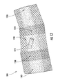
- FIG. 13 is a front view of a plurality of pouches manufactured using an RF welding technique, according to one illustrated embodiment.
- a surgical environment will be used as an example environment for detecting objects but such should not be considered limiting.
- FIG. 1A shows a surgical environment 100 in which medical procedures are performed, for example a surgical environment, clinician's office, examination room, patient room or other environments in which medical procedures may be performed.
- a medical provider 102 operates an identification and detection system 104 to ascertain the presence or absence of objects 106 in, or on, a patient 108 , for example in or on a surgical site or area or cavity 105 , and/or an identity of such objects 106 .
- the object 106 may take a variety of forms, for example instruments, accessories and/or disposable objects useful in performing surgical procedures.
- the object 106 may take the form of scalpels, scissors, forceps, hemostats, dilators, needles, a drill bit, and/or clamps or other surgically useful objects.
- the objects 106 may take the form of surgical sponges, gauze and/or padding.
- the surgical sponges, gauze and/or padding may be, as examples, 2 inches by 2 inches, 4 inches by 4 inches, 12 inches by 12 inches, or other sizes. Such dimensions may refer to the surgical sponges, gauze and/or padding as folded or otherwise packaged.
- the object 106 is tagged, carrying, attached or otherwise coupled to a wirelessly detectable object 118 .
- a wirelessly detectable object 118 is physically coupled to or otherwise physically associated with each object 106 used within the surgical environment 100 .
- the wirelessly detectable object 118 includes one or more transponders that receive and respond to wireless signals.
- the wirelessly detectable object 118 includes a radio frequency identification (RFID) transponder 120 that, when interrogated, wirelessly returns a first response signal that contains identification information associated with the wirelessly detectable object 118 .
- the wirelessly detectable object 118 includes a presence transponder 122 that, when interrogated, wirelessly returns a second response signal that does not contain identification information.
- RFID radio frequency identification
- the medical provider 102 can operate the identification and detection system 104 to determine the presence or absence of wirelessly detectable object 118 through wireless interrogation of the presence transponder 122 and/or to obtain identification information through wireless interrogation of the RFID transponder 120 .
- respective interrogation of and response by the presence transponder 122 and the RFID transponder 120 can occur in two different frequency ranges.
- the frequency range associated with interrogation of and response by the presence transponder 122 can include lower frequencies than the frequency range associated with interrogation of and response by the RFID transponder 120 . Such lower frequencies may enable superior transmission of signals through bodily tissues or other obstacles including membranes, skin, flesh, etc.
- interrogation of and response by the presence transponder 122 is possible at larger physical distances than interrogation of and response by the RFID transponder 120 .
- the RFID transponder 120 includes an integrated circuit electrically coupled to an antenna.
- the RFID transponder 120 may be relatively small, such as, for example, approximately 12 millimeters in diagonal.
- the antenna can include an inductive winding such as a conductive wire wound about a core.
- the core can be fabricated from a ferrite rod.
- the inductive winding is electrically coupled to an integrated circuit.
- the antenna includes a conductive trace or other structures.
- the RFID transponder 120 may be an active device that includes a local power source such as a battery or may be a passive device that relies on energy in the interrogation signal to power the transponder 120 .
- the RFID transponder 120 takes the form of any one of various commercially-available RFID devices that include an RFID integrated circuit and/or front end.
- the RFID transponder 120 is operable to transmit (e.g., via active radiation of the antenna) a first response signal that contains identification information, in response to receiving an interrogation signal in a first frequency range.
- the first response signal encodes the identification information stored by the integrated circuit.
- the RFID transponder 122 may be denominated as a “smart” transponder.
- the identification information included in the first response signal may be a unique identifier (i.e., unique over a set of all otherwise identical RFID transponders 120 ).
- the identifier may not be unique, for example, a set of RFID transponders 120 may each have the same identifier.
- some portion of the identification information or some other identification information may not be unique, for example, a portion representing a manufacturer, a lot, or a type, may be shared between transponders 120 from the same manufacturer, lot or of the same type.
- the identification information can be associated with a type of the object 106 or an attribute thereof.
- the identification information can be linked to the type or attribute using a database, lookup table, or other data structure that cross-references unique identifiers with the type or attribute.
- the identification information can include the desired attribute, pre-stored or written onto the integrated circuit, and directly convey the pre-stored attribute via the first response signal.
- the RFID transponder 120 is a printable and/or ultra-low-cost RFID transponder 120 that is not necessarily intended to maintain functionality when the object 106 is used within the surgical environment 100 .
- the RFID transponder 120 is interrogated at a conclusion of or during a manufacturing process, for example, to ensure that an appropriate number of objects 106 are included in a shipping tote or other package. After such use, the RFID transponder 120 may not be expected to provide further use and may allowably degrade or otherwise experience damage if the object 106 is used within the surgical environment 100 (e.g., in vivo). Such may permit inclusion of low-cost RFID transponders 120 for use in manufacturing without requiring a hardened or rugged encapsulant or transponder body to protect the transponders 120 during surgical procedures.
- the presence transponder 122 may be constructed in various manners.
- the presence transponder 122 may include a ferrite rod with a conductive coil wrapped about an exterior surface thereof to form an inductor, and a capacitor coupled to the conductive coil to form a series circuit.
- the conductive coil may, for example, take the form of a spiral wound conductive wire with an electrically insulative sheath or sleeve.
- the inductive coil and capacitor may together form an inductive/capacitance (L/C) tank circuit. Additional details about types of transponders may be found in U.S. Provisional Patent Application Ser. No. 60/811,376 filed Jun. 6, 2006 and U.S. Provisional Patent Application Ser. No. 60/892,208, filed Feb. 28, 2007, both of which are incorporated herein by reference.
- the presence transponder 122 is operable to transmit (e.g., via radiation of the inductive coil) a second response signal, in response to receiving an interrogation signal in a second frequency range.
- the second response signal does not include any unique identifying information and, therefore, indicates only that the presence transponder 122 is present.
- the presence transponder 122 may be denominated as a “dumb” transponder.
- presence transponder 122 provides superior response strength through bodily tissue relative to the RFID transponder 120 .
- the presence transponder 122 may be relatively small, for example approximately 5-10 millimeters long with a diameter of about 1-4 millimeters.
- an encapsulant advantageously protects the transponder from the ambient environment, for instance from forces, pressure and/or fluids, such as bodily fluids.
- the presence transponder 122 includes a dumbbell-shaped ferrite rod having broad end portions and a narrow intermediate portion. The broad end portions may provide capacitive functionality. In other implementations, the presence transponder 122 may be shaped as a fusiform-shaped object, with truncated ends.
- the wirelessly detectable object 118 includes at least one directional antenna.
- an active antenna element of the RFID transponder 120 forms at least a portion of the directional antenna.
- the wirelessly detectable object does not include the presence transponder 122 . Particular example structures and arrangements of the wirelessly detectable object 118 are discussed further below with reference to the Figures that follow.
- FIG. 1B depicts the wirelessly detectable object 118 as physically coupled to and visible upon an external surface of the object 106 , such depiction is provided for ease of illustration and description only.
- the piece of absorbent material 106 may be folded or otherwise manipulated such that the wirelessly detectable object 118 is no longer carried on an external surface of the piece of absorbent material 106 and/or externally visible.
- the piece of absorbent material 106 may be folded into quadrants to provide, for example, a folded sponge, gauze, or padding that has four discernable layers.
- the wirelessly detectable object 118 may be internally carried between layers of the piece of absorbent material 106 and visible only upon unfolding of the piece of absorbent material 106 .
- the identification and detection system 104 includes a controller 110 , and an interrogation device or assembly, such as an antenna 112 coupled to the controller 110 by one or more communication paths, for example a coaxial cable 114 .
- the antenna 112 may take the form of a hand-held wand 116 .
- the antenna 112 is sized to fit at least partially in the cavity 105 .
- the controller 110 is configured to cause the antenna 112 to emit one or more wireless interrogation signals in one or more frequency bands, to receive responses to such interrogation signals from one or more wirelessly detectable objects 118 , and to determine the presence or absence and/or identity of the wirelessly detectable objects 118 or associated objects 106 based on the received response signals, if any.
- the wand 116 can be configured to emit a first interrogation signal in a first frequency range and can include an integrated circuit tag reader, such as an RFID reader as is known, to receive the first response signal from the RFID transponder 120 and decode the identifier.
- the wand 116 can further be configured to emit a second interrogation signal in a second frequency, to receive the second response signal from the presence transponder 122 , and to provide an indication of presence of the object 106 when the second response signal is received.
- Components configured for emission of the interrogation signals and for receiving the first and second response signals can be selected from any suitable scanning technology, including, but not limited to, the detection device disclosed in U.S. Pat. No. 6,026,818, to Blair et al., and that disclosed in U.S. Pat. No. 7,696,877, to Barnes et al., both of which are incorporated herein by reference.
- the controller 110 of the interrogation device or assembly includes an interface that displays the name of the objects 106 as the wand 116 scans the objects 106 after surgery.
- the interface may display an accounting or inventory of sponges, gauzes, padding, hemostats, clamps, forceps, scissors, scalpels, or other surgical tools or accessories, or any other objects 106 , for an expedient accounting of the objects 106 .
- a user such as the medical provider 102 can scan the patient 108 to detect presence or absence of wirelessly detectable objects 118 and their corresponding objects 106 within the patient 108 through wireless interrogation of one or more presence transponders 122 .
- interrogation of the presence transponders 122 can occur at a first physical distance.
- the medical provider 102 can immediately scan the region of detection to wirelessly interrogate one or more RFID transponders 120 and thereby identify the one or more objects 106 that remain.
- such interrogation of the RFID transponders 120 can occur at a second physical distance that is less than the first physical distance.
- the medical provider 102 can make informed decisions with respect to handing of the object 106 .
- the medical provider 102 can remove object prior to closing patent.
- the medical provider 102 can scan the present objects 106 to ensure that all the objects 106 that were present before surgery, are now present and outside of the body of the patient 108 after surgery. For example, the medical provider can interrogate the RFID transponder 120 of each wirelessly detectable object 118 to identify all present objects 106 . The presently identified objects 106 can be compared to a list of objects 106 identified and logged prior to use within the surgical environment to detect any discrepancies (i.e., missing objects).
- one or more RFID transponders 120 for one or more objects 106 may be interrogated at a conclusion of or during a manufacturing process, for example, to ensure that an appropriate number of objects 106 are included in a shipping tote or other package.
- the RFID transponders 120 may or may not degrade.
- the medical provider 102 may still interrogate one or more presence transponders 122 to advantageously detect presence or absence of wirelessly detectable objects 118 and their corresponding objects 106 within the patient 108 .
- the wirelessly detectable objects 118 of the present disclosure provide the capability to efficiently detect objects 106 that may be present in or on the body of the patient 108 , and the capability to conduct an inventory of present objects 106 after surgery to ensure all objects 106 used during surgery are present, without the use of multiple separately affixed optically-readable tags and without the need to conduct a manual count of the objects by highly trained and highly paid personnel.
- interrogation and detection system 104 may similarly be used on animals or inanimate subjects.
- FIG. 2A is a front view 200 of a pouch 202 that includes a presence transponder 206 , according to one illustrated embodiment.
- the wirelessly detectable object 118 includes a pouch 202 that holds or otherwise retains a presence transponder 206 within an interior cavity of the pouch 202 .
- the pouch 202 is physically coupleable to an object 106 such as a piece of absorbent material.
- the presence transponder 206 is freely movable within the interior cavity of the pouch 202 . Such may advantageously allow folding, stretching, compression, twisting, or other physical manipulation of the piece of absorbent material or other object 106 without causing damage to the presence transponder 206 .
- the presence transponder 206 freely moves within the pouch 202 to an advantageous position experiencing reduced forces.
- the free-floating presence transponder 206 does not inhibit folding, stretching, compression, twisting, or other physical manipulation of the piece of absorbent material or other object 106 which may be necessary for the surgical procedure.
- the pouch 202 includes at least a first flexible layer 208 that forms the interior cavity.
- the first flexible layer 208 can be physically coupled to a surface of an object 106 such as a piece of absorbent material to form the interior cavity therebetween.
- the pouch 202 includes a second flexible layer 210 opposite the first flexible layer 208 and physically coupled to the first flexible layer 208 to form the interior cavity therebetween.
- a radio frequency (RF) weld 204 physically couples the first flexible layer 208 to the second flexible layer 210 .
- the RF weld 204 extends around a perimeter of the interior cavity and seals the presence transponder 206 within the pouch 202 .
- a width of the RF weld 204 can be varied to balance various objectives such as a strength of weld 204 and a size of the pouch 202 .
- adhesives, stitching, clamping, fasteners, or other securing means can physically couple the first flexible layer 208 to the object 106 or the second flexible layer 210 .
- the first and/or second flexible layers 208 and 210 may be fabric laminates or other materials.
- the first and/or second flexible layers 208 and 210 may be one or more of thermoplastic polyurethane (TPU) and nylon fabric; polyvinyl chloride (PVC) impregnated fabric; layer(s) of PVC, TPU, PET, PETG, LDPE, EVA, open celled polyurethanes, or nylon; other fabrics (e.g., cotton); other plastics; or combinations thereof.
- TPU thermoplastic polyurethane
- PVC polyvinyl chloride
- the flexible layers 208 and 210 are typically relatively thin and may be absorbent or non-absorbent.
- the flexible layers are of material suitable to prevent entry of fluids into the interior cavity of the pouch 202 (e.g., due to a water-proof or water-resistant coating).
- the first and/or second flexible layers 208 and 210 may be soft, pliable, and resistant to ripping or tearing.
- the first flexible layer 208 includes a first layer of TPU and a first layer of nylon fabric.
- the second flexible layer 210 includes a second layer of TPU and a second layer of nylon fabric.
- the first and second layers of TPU may respectively be located interior relative to the first and second layers of nylon fabric.
- the first and second layers of TPU may contact each other and may form an interior surface of the interior cavity of the pouch 202 while the first and second layers of nylon fabric are respectively carried by respective exterior surfaces of the first and second layers of TPU that are opposite to the interior cavity.
- the first and second layers of nylon fabric may be located interior relative to the first and second layers of TPU or may be embedded within the first and second layers of TPU.
- FIG. 2B is another front view 250 of a pouch 252 that includes a presence transponder 256 , according to one illustrated embodiment.
- pouch 252 includes a first flexible layer 258 physically coupled to a second flexible layer 260 by an RF weld 254 .
- the presence transponder 256 is received and freely movable within an interior cavity formed between the first and second flexible layers 258 and 260 .
- the RF weld 254 extends around a perimeter of the interior cavity and seals the presence transponder 256 within the interior cavity of the pouch 252 .
- the pouch 252 is physically coupleable to an object 106 such as a piece of absorbent material.
- FIG. 3 is a front view 300 of a piece of absorbent material 302 with a wirelessly detectable object physically coupled thereto, according to one illustrated embodiment.
- an RFID transponder 306 and a presence transponder 312 are physically associated with the piece of absorbent material 302 .
- a pouch 304 is physically coupled to the piece of absorbent material 302 .
- the pouch 304 includes a first flexible layer physically coupled to a second flexible layer to form an interior cavity therebetween.
- the flexible layers may the same as or similar to layers 208 and 210 discussed with reference to FIG. 2A .
- a presence transponder 312 is retained and freely movable within the interior cavity of the pouch 304 .
- An RF weld 310 physically couples the first flexible layer to the second flexible layer.
- the RF weld 310 further physically couples the pouch 304 to the piece of absorbent material 302 .
- an additional RF weld or other securing means physically couples the pouch 304 to the piece of absorbent material.
- the RFID transponder 306 is physically coupled to the piece of absorbent material 302 separately from the pouch 304 .
- Adhesives, stitching, clamping, fasteners, heat sealing, RF welding, or other securing means physically couple the RFID transponder 306 the piece of absorbent material 302 .
- a radiopaque thread or object 308 is woven into or otherwise physically coupled to the piece of absorbent material 302 , as well.
- FIG. 3 depicts pouch 304 and RFID transponder 306 as physically coupled to and visible upon an external surface of the object piece of absorbent material 302
- the piece of absorbent material 306 is be folded or otherwise manipulated such that the pouch 304 and RFID transponder 306 are internally carried between layers of the piece of absorbent material 302 .
- FIG. 4 is a front view 400 of a pouch 402 that includes a presence transponder 408 freely movable within an interior cavity and an RFID transponder 410 with an antenna trace 412 , according to one illustrated embodiment.
- the pouch 402 includes a first flexible layer 404 physically coupled to a second flexible layer 405 to form an interior cavity therebetween.
- the flexible layers 404 and 405 may the same as or similar to layers 208 and 210 discussed with reference to FIG. 2A .
- the presence transponder 408 is retained and freely movable within the interior cavity of the pouch 402 .
- an RF weld 406 physically couples the first flexible layer 404 to the second flexible layer 405 and seals the presence transponder 408 within the interior cavity.
- the RFID transponder 410 includes an antenna trace 412 electrically coupled to a chip 414 .
- An integrated circuit that stores identification information can form all or a portion of the chip 414 .
- All or a portion of the RFID transponder 410 can be embedded in and/or adhered to the first flexible layer 404 .
- the chip 414 is adhered to the first flexible layer 404 (e.g., adhered to a surface of the first layer 404 that faces the interior cavity) while the antenna trace 412 is embedded within the first flexible layer 404 .
- the antenna trace 412 is printed or traced onto the first flexible layer 404 (e.g., onto an interior surface that faces the interior cavity).
- all or a portion of the RFID transponder 410 is embedded in and/or adhered to the second flexible layer 405 .
- At least a portion of the first flexible layer 404 and/or the second flexible layer 405 is a material that is absorbent but remains electrically insulative, thereby contributing to an absorbency of an attached piece of absorbent material without interfering with an ability of the antenna trace 412 to transmit a signal.
- the presence transponder 408 is freely movable within the interior cavity of the pouch 402 and the RFID transponder 410 is embedded in and/or adhered to the first flexible layer 404 , the presence transponder 408 is independently movable with respect to the RFID transponder 410 . Furthermore, as shown in FIG. 4 , in some implementations, care is taken to prevent the RF weld 406 from welding over and potentially damaging the antenna trace 412 .
- FIG. 5A is a top view of a pouch 502 , according to one illustrated embodiment.
- FIG. 5B is an exploded isometric view of the pouch 502 that includes a presence transponder 508 b freely movable within an interior cavity formed between a first flexible layer 504 b and a substrate 506 b of the pouch, according to one illustrated embodiment.
- An RFID transponder 512 b is adhered to the substrate 506 b .
- An encapsulant 510 encapsulates the presence transponder 508 b .
- the substrate 506 b can be a second flexible layer, a surgical object such as a piece of absorbent material, or other substrates.
- first flexible layer 504 b and the substrate 506 b may the same as or similar to layers 208 and 210 discussed with reference to FIG. 2A .
- an RF weld physically couples the first flexible layer 504 b to the substrate 506 b.
- FIG. 5C is first and second exploded side views of the pouch 502 that includes the presence transponder 508 c freely movable within the interior cavity formed between the first flexible layer 504 c and the substrate 506 c of the pouch, according to one illustrated embodiment.
- the RFID transponder 512 c is adhered to the substrate 506 c of the pouch 502 .
- some or all of the RFID transponder 512 c e.g., a chip portion
- some or all of the RFID transponder 512 c e.g., an antenna portion
- FIG. 6A is a top view of a pouch 602 , according to one illustrated embodiment.
- FIG. 6B is an exploded isometric view of the pouch 602 that includes a presence transponder 608 b and an RFID transponder 612 b freely movable within an interior cavity formed between a first flexible layer 604 b and a substrate 606 b of the pouch, according to one illustrated embodiment.
- An encapsulant 610 encapsulates the presence transponder 608 b .
- the substrate 606 b can be a second flexible layer, a surgical object such as a piece of absorbent material, or other substrates.
- the first flexible layer 604 b and the substrate 606 b may the same as or similar to layers 208 and 210 discussed with reference to FIG. 2A .
- an RF weld physically couples the first flexible layer 604 b to the substrate 606 b.
- FIG. 6C is first and second exploded side views of the pouch 602 that includes the presence transponder 608 c and the RFID transponder 612 c freely movable within the interior cavity formed between the first flexible layer 604 c and the substrate 606 c of the pouch, according to one illustrated embodiment.
- FIG. 7 is a cross-sectional diagram of a wirelessly detectable object 700 that includes a directional antenna formed on or within a pouch 701 , according to one illustrated embodiment.
- the pouch 701 includes a first flexible layer 702 physically coupled to a substrate 704 to form an interior cavity 706 therebetween.
- a presence transponder 708 is received and freely movable within the interior cavity 706 .
- the substrate 704 can be a second flexible layer, a surgical object such as a piece of absorbent material, or other substrates.
- the first flexible layer 702 and the substrate 704 may the same as or similar to layers 208 and 210 discussed with reference to FIG. 2A .
- the wirelessly detectable object further includes an RFID transponder 710 that includes at least one active antenna element 712 and an integrated circuit 714 .
- the integrated circuit 714 can actively drive or energize the active antenna element 712 of the RFID transponder 710 to transmit a signal.
- the wirelessly detectable object 700 further includes at least one passive antenna element 716 that, together with the active antenna element 712 , operates as a directional antenna.
- the passive antenna element 716 and the active antenna element 712 may together operate as a Yagi antenna.
- the passive antenna element 716 can be a separate structure from the active antenna element 712 of the RFID transponder 710 .
- the passive antenna element 716 and the active antenna element 712 may be included within a single integral structure.
- two or more passive antenna elements 716 act as a reflector element and a director element, respectively.
- the passive antenna element 716 is adhered to or traced upon an interior surface of the first flexible layer 702 that faces the interior cavity 706 .
- the passive antenna element 716 may be at least partially embedded in the first flexible layer 702 or adhered to or traced upon an exterior surface of the first flexible layer 702 .
- the active antenna element 712 is adhered to or traced upon an interior surface of the substrate 704 that faces the interior cavity 706 .
- the active antenna element 712 may be at least partially embedded within the substrate 704 or adhered to or traced upon an exterior surface of the substrate 704 .
- the respective positions of the active antenna element 712 and the passive antenna element 716 may be opposite to those depicted in FIG. 7 . That is, the passive antenna element 716 may be adhered to or embedded within the substrate 704 while the active antenna element 712 is adhered to or embedded within the first flexible layer 702 .
- FIG. 8 is a cross-sectional diagram of a wirelessly detectable object 800 that includes a directional antenna carried at least in part by a first substrate 802 , according to one illustrated embodiment.
- the wirelessly detectable object 800 further includes an RFID transponder 806 and a presence transponder 812 physically coupled to the first substrate 802 .
- the wirelessly detectable object 800 is physically coupled to a piece of absorbent material 804 .
- the first substrate 802 may be a first flexible layer.
- the first substrate 802 may be the same as or similar to layers 208 and 210 discussed with reference to FIG. 2A .
- the RFID transponder 806 includes an active antenna element 808 and an integrated circuit 810 .
- the integrated circuit 810 may selectively actively energize or otherwise cause the active antenna element 808 to radiate to transmit a signal.
- the wirelessly detectable object 800 further includes at least one passive antenna element 814 that, together with the active antenna element 808 , operates as a directional antenna.
- the passive antenna element 814 and the active antenna element 808 may together operate as a Yagi antenna.
- the passive antenna element 814 is positioned between the first substrate 802 and the piece of absorbent material 804 .
- the passive antenna element 814 can be adhered to, traced onto, or otherwise carried by one or both of the first substrate 802 and/or the piece of absorbent material 804 .
- at least a portion of the passive antenna element 814 is embedded within or forms a portion of the first substrate 802 or the piece of absorbent material 804 .
- the respective positions of the active antenna element 808 and the passive antenna element 814 may be opposite to those depicted in FIG. 8 . That is, the passive antenna element 814 may be adhered to or carried by a surface of the first substrate 802 that is opposite the piece of absorbent material 804 while the active antenna element 808 is positioned between the first substrate 802 and the piece of absorbent material 804 .
- FIG. 8 depicts first substrate 802 as not contacting the piece of absorbent material 804
- the first substrate 802 is physically coupled to (e.g., by an RF weld) the piece of absorbent material 804 .
- the wirelessly detectable object 800 does not include the presence transponder 812 .
- FIG. 9 is a cross-sectional diagram of a wirelessly detectable object 900 that includes a directional antenna carried at least in part by a first substrate 902 , according to one illustrated embodiment.
- the wirelessly detectable object 900 is physically coupled to a piece of absorbent material 916 .
- the wirelessly detectable object 900 includes an RFID transponder 906 and a presence transponder 910 physically coupled to the first substrate 902 .
- the wirelessly detectable object 900 further includes a second substrate 904 .
- the first substrate 902 and/or the second substrate 904 may be flexible layers.
- the first substrate 902 and/or the second substrate 904 may be the same as or similar to layers 208 and 210 discussed with reference to FIG. 2A .
- the RFID transponder 906 includes an active antenna element 908 and an integrated circuit 910 .
- the integrated circuit 910 may selectively actively energize or otherwise cause the active antenna element 908 to radiate to transmit a signal.
- the wirelessly detectable object 900 further includes at least one passive antenna element 914 that, together with the active antenna element 908 , operates as a directional antenna.
- the passive antenna element 914 and the active antenna element 908 may together operate as a Yagi antenna.
- the passive antenna element 914 is positioned between the first substrate 902 and the second substrate 904 .
- the passive antenna element 914 can be adhered to, traced onto, or otherwise carried by one or both of the first substrate 902 and/or the second substrate 904 .
- at least a portion of the passive antenna element 914 is embedded within or forms a portion of the first substrate 902 or the second substrate 904 .
- the respective positions of the active antenna element 908 and the passive antenna element 914 may be opposite to those depicted in FIG. 9 . That is, the passive antenna element 914 may be adhered to or carried by a surface of the first substrate 902 that is opposite the second substrate 904 while the active antenna element 908 is positioned between the first substrate 902 and the second substrate 904 . Further, in some implementations, one or more RF welds or other securing means physically couple one or both of the first and second substrates 902 and 904 to the piece of absorbent material 916 .
- FIG. 9 depicts first substrate 802 as not contacting the second substrate 904
- the first substrate 902 is physically coupled to (e.g., by an RF weld) the second substrate 904 .
- an RF weld may physically couple the second substrate 904 to the piece of absorbent material.
- the wirelessly detectable object 900 does not include the presence transponder 910 .
- FIG. 10 is a schematic diagram 1000 of a method for manufacturing wirelessly detectable objects using RF welding, according to one illustrated embodiment.
- the method may include providing a first flexible layer 1002 and a second flexible layer 1004 .
- first flexible layer 1002 and the second flexible layer 1004 may be the same as or similar to layers 208 and 210 discussed with reference to FIG. 2A .
- the first and/or second flexible layers 1002 and 1004 may be provided as rolls or sheets of flexible layers.
- the method may further include RF welding the first flexible layer 1002 to the second flexible layer 1004 to form a plurality of pouches (e.g., pouches 1012 a and 1012 b ).
- Each of the plurality of pouches can be formed by a set of RF welds.
- an RF welding machine 1008 can be used to create a plurality of RF welds that physically couple the first flexible layer 1002 to the second flexible layer 1004 and create the plurality of pouches 1012 a and 1012 b .
- Each set of RF welds can take the form of a hollowed rectangle, circle, oval, or other shape to form an interior cavity within a perimeter of the hollowed area.
- One or more transponders can be sealed within the interior cavity of each pouch 1012 .
- the first and second flexible layers 1002 and 1004 are transformed into a sheet or roll of pouches 1010 , with each pouch 1012 retaining one or more transponders.
- the pouches 1012 may come as a roll of pouches 1010 each containing one or more respective transponders. Having the pouches 1012 come in a roll 1010 enhances the efficiency in the manufacturing process, as all that remains to be done is cutting or separating the pouches 1012 from the roll 1010 and attaching each of the pouches 1012 to a respective surgical object.
- FIG. 11 shows flexible layers usable to manufacture a plurality of pouches, according to one illustrated embodiment.
- FIG. 11 shows a first flexible layer 1102 of thermoplastic polyurethane and a second flexible layer 1104 of nylon.
- the above noted materials are provided as examples only.
- the flexible layers 1102 and 1104 may be the same as or similar to layers 208 and 210 discussed with reference to FIG. 2A .
- FIG. 12 shows manufacture of a plurality of pouches using an RF welding technique, according to one illustrated embodiment.
- FIG. 12 shows the first flexible layer 1102 of thermoplastic polyurethane and the second flexible layer 1104 of nylon.
- An RF welding machine 1210 is used to generate a plurality of RF welds to physically couple layer 1102 to layer 1104 and form a plurality of pouches.
- an RF weld 1214 forms at least a portion of a perimeter of an interior cavity of an unfinished pouch 1212 .
- One or more transponders may be positioned between layers 1102 and 1104 and then sealed within the pouch 1212 by an additional RF weld.
- the pouches may be made by RF welding the first layer 1102 to the second layer 1104 where a series of cavities for receiving one or more corresponding transponders are made by providing bulges in the first layer 1102 and/or the second layer 1104 .
- the bulges may be formed by bunching or stretching the material of the first layer 1102 and/or the second layer 1104 .
- FIG. 13 is a front view 1300 of a plurality of pouches 1302 , 1304 , and 1306 manufactured using the RF welding technique illustrated in FIGS. 10 and 12 , according to one illustrated embodiment.
- a plurality of RF welds form each of pouches 1302 , 1304 , and 1306 .
- RF welds 1308 and 1310 form at least a portion of a perimeter of an interior cavity of pouch 1304 .
- a presence transponder 1312 is received and freely movable within the interior cavity of pouch 1304 .
- Pouches 1302 and 1306 are bisected for the purposes of illustration.
- the pouches 1302 , 1304 , and 1306 may be physically separated (e.g., cut apart) and then respectively physically coupled to surgical objects to act as wirelessly detectable objects.
- the transponder device may be used to mark objects anytime detection of the presence of marked objects is desirable in a confined area, not just during surgery. For example, it may be used to make sure marked objects are not left inside a machine (e.g., vehicle, copy machine) after maintenance is performed.
- the transponder housing may be utilized to mark objects to determine the removal of a marked object from a confined area, such as a cover-all garment from a clean room of a semiconductor fabrication plant.
- an interrogation device for example, may be placed proximate to a door of the confined area.
- a transponder housing or cover may be manufactured and distributed for tagging objects without a transponder currently attached.
- the housing can then be used to place a transponder compatible with a particular detection and interrogation system at a subsequent time, including by the end-user.
Abstract
Description
Claims (34)
Priority Applications (1)
| Application Number | Priority Date | Filing Date | Title |
|---|---|---|---|
| US15/003,515 US9717565B2 (en) | 2015-01-21 | 2016-01-21 | Wirelessly detectable objects for use in medical procedures and methods of making same |
Applications Claiming Priority (2)
| Application Number | Priority Date | Filing Date | Title |
|---|---|---|---|
| US201562106052P | 2015-01-21 | 2015-01-21 | |
| US15/003,515 US9717565B2 (en) | 2015-01-21 | 2016-01-21 | Wirelessly detectable objects for use in medical procedures and methods of making same |
Publications (2)
| Publication Number | Publication Date |
|---|---|
| US20160206399A1 US20160206399A1 (en) | 2016-07-21 |
| US9717565B2 true US9717565B2 (en) | 2017-08-01 |
Family
ID=55701669
Family Applications (1)
| Application Number | Title | Priority Date | Filing Date |
|---|---|---|---|
| US15/003,515 Active US9717565B2 (en) | 2015-01-21 | 2016-01-21 | Wirelessly detectable objects for use in medical procedures and methods of making same |
Country Status (5)
| Country | Link |
|---|---|
| US (1) | US9717565B2 (en) |
| EP (2) | EP3235463B1 (en) |
| CN (1) | CN105796182B (en) |
| AU (1) | AU2016200113B2 (en) |
| ES (1) | ES2639262T3 (en) |
Cited By (28)
| Publication number | Priority date | Publication date | Assignee | Title |
|---|---|---|---|---|
| US10595958B2 (en) | 2008-10-28 | 2020-03-24 | Covidien Lp | Wirelessly detectable objects for use in medical procedures and methods of making same |
| US10660726B2 (en) | 2015-01-21 | 2020-05-26 | Covidien Lp | Sterilizable wirelessly detectable objects for use in medical procedures and methods of making same |
| US10709521B2 (en) | 2016-07-11 | 2020-07-14 | Covidien Lp | Method and apparatus to account for transponder tagged objects used during clinical procedures, employing a shielded receptacle |
| US10716641B2 (en) | 2018-03-27 | 2020-07-21 | Covidien Lp | Method and apparatus to account for transponder tagged objects used during clinical procedures, employing a trocar |
| US10770178B2 (en) | 2016-07-11 | 2020-09-08 | Covidien Lp | Method and apparatus to account for transponder tagged objects used during clinical procedures employing a shielded receptacle with antenna |
| US10784920B2 (en) | 2018-10-04 | 2020-09-22 | Covidien Lp | Wirelessly detectable object that emits a variable-frequency response signal, and method and system for detecting and locating same |
| US10835348B2 (en) | 2016-07-11 | 2020-11-17 | Covidien Lp | Method and apparatus to account for transponder tagged objects used during clinical procedures, for example including count in and/or count out and presence detection |
| US10849713B2 (en) | 2018-03-27 | 2020-12-01 | Covidien Lp | Method and apparatus to account for transponder tagged objects used during clinical procedures, employing a trocar |
| US10874560B2 (en) | 2015-01-21 | 2020-12-29 | Covidien Lp | Detectable sponges for use in medical procedures and methods of making, packaging, and accounting for same |
| US10888394B2 (en) | 2015-02-26 | 2021-01-12 | Covidien Lp | Apparatuses to physically couple transponder to objects, such as surgical objects, and methods of using same |
| US11000226B2 (en) * | 2018-11-09 | 2021-05-11 | DePuy Synthes Products, Inc. | Methods and apparatus for alignment of sensor communication devices with implanted bone healing sensors |
| US11065080B2 (en) | 2016-07-11 | 2021-07-20 | Covidien Lp | Method and apparatus to account for transponder tagged objects used during clinical procedures, employing a trocar |
| US11076997B2 (en) | 2017-07-25 | 2021-08-03 | Smith & Nephew Plc | Restriction of sensor-monitored region for sensor-enabled wound dressings |
| US11324424B2 (en) | 2017-03-09 | 2022-05-10 | Smith & Nephew Plc | Apparatus and method for imaging blood in a target region of tissue |
| US11559438B2 (en) | 2017-11-15 | 2023-01-24 | Smith & Nephew Plc | Integrated sensor enabled wound monitoring and/or therapy dressings and systems |
| US11596553B2 (en) | 2017-09-27 | 2023-03-07 | Smith & Nephew Plc | Ph sensing for sensor enabled negative pressure wound monitoring and therapy apparatuses |
| US11633153B2 (en) | 2017-06-23 | 2023-04-25 | Smith & Nephew Plc | Positioning of sensors for sensor enabled wound monitoring or therapy |
| US11633147B2 (en) | 2017-09-10 | 2023-04-25 | Smith & Nephew Plc | Sensor enabled wound therapy dressings and systems implementing cybersecurity |
| US11638664B2 (en) | 2017-07-25 | 2023-05-02 | Smith & Nephew Plc | Biocompatible encapsulation and component stress relief for sensor enabled negative pressure wound therapy dressings |
| US11690570B2 (en) | 2017-03-09 | 2023-07-04 | Smith & Nephew Plc | Wound dressing, patch member and method of sensing one or more wound parameters |
| US11717447B2 (en) | 2016-05-13 | 2023-08-08 | Smith & Nephew Plc | Sensor enabled wound monitoring and therapy apparatus |
| US11759144B2 (en) | 2017-09-10 | 2023-09-19 | Smith & Nephew Plc | Systems and methods for inspection of encapsulation and components in sensor equipped wound dressings |
| US11791030B2 (en) | 2017-05-15 | 2023-10-17 | Smith & Nephew Plc | Wound analysis device and method |
| US11839464B2 (en) | 2017-09-28 | 2023-12-12 | Smith & Nephew, Plc | Neurostimulation and monitoring using sensor enabled wound monitoring and therapy apparatus |
| US11883262B2 (en) | 2017-04-11 | 2024-01-30 | Smith & Nephew Plc | Component positioning and stress relief for sensor enabled wound dressings |
| US11925735B2 (en) | 2017-08-10 | 2024-03-12 | Smith & Nephew Plc | Positioning of sensors for sensor enabled wound monitoring or therapy |
| US11931165B2 (en) | 2017-09-10 | 2024-03-19 | Smith & Nephew Plc | Electrostatic discharge protection for sensors in wound therapy |
| US11944418B2 (en) | 2018-09-12 | 2024-04-02 | Smith & Nephew Plc | Device, apparatus and method of determining skin perfusion pressure |
Families Citing this family (11)
| Publication number | Priority date | Publication date | Assignee | Title |
|---|---|---|---|---|
| US8600478B2 (en) | 2007-02-19 | 2013-12-03 | Medtronic Navigation, Inc. | Automatic identification of instruments used with a surgical navigation system |
| US8264342B2 (en) | 2008-10-28 | 2012-09-11 | RF Surgical Systems, Inc | Method and apparatus to detect transponder tagged objects, for example during medical procedures |
| US9792408B2 (en) | 2009-07-02 | 2017-10-17 | Covidien Lp | Method and apparatus to detect transponder tagged objects and to communicate with medical telemetry devices, for example during medical procedures |
| US9226686B2 (en) | 2009-11-23 | 2016-01-05 | Rf Surgical Systems, Inc. | Method and apparatus to account for transponder tagged objects used during medical procedures |
| US9872732B2 (en) | 2013-10-24 | 2018-01-23 | Covidien Lp | Surgical sponge distribution systems and methods |
| CN110680516A (en) | 2014-03-31 | 2020-01-14 | 柯惠Lp公司 | Transponder detection device |
| AU2016200113B2 (en) | 2015-01-21 | 2019-10-31 | Covidien Lp | Wirelessly detectable objects for use in medical procedures and methods of making same |
| US9690963B2 (en) | 2015-03-02 | 2017-06-27 | Covidien Lp | Hand-held dual spherical antenna system |
| ES1233247Y (en) * | 2019-02-11 | 2019-10-23 | Sanchez Ernesto Sanchez | Radiofrequency surgical dressing detection device |
| US11620464B2 (en) | 2020-03-31 | 2023-04-04 | Covidien Lp | In-vivo introducible antenna for detection of RF tags |
| US20230060843A1 (en) * | 2021-08-25 | 2023-03-02 | Covidien Lp | Inventory systems and methods for detecting and counting potentially retained surgical items |
Citations (212)
| Publication number | Priority date | Publication date | Assignee | Title |
|---|---|---|---|---|
| US2740405A (en) | 1948-08-04 | 1956-04-03 | Howard C Riordan | Surgical sponge with radioactive tracer |
| US3422816A (en) | 1964-12-09 | 1969-01-21 | Johnson & Johnson | Surgical dressing |
| US4114601A (en) | 1976-08-09 | 1978-09-19 | Micro Tec Instrumentation, Inc. | Medical and surgical implement detection system |
| US4193405A (en) | 1976-08-09 | 1980-03-18 | Micro Tec Instrumentation Inc. | Detectable medical and surgical implements |
| US4477256A (en) | 1982-02-11 | 1984-10-16 | Win Hirsch | Surgical sponge |
| WO1986002539A1 (en) | 1984-11-01 | 1986-05-09 | Pekka Johannes Nyberg | Device for localizing metal objects in a human or animal body |
| US4626251A (en) | 1985-02-22 | 1986-12-02 | Albert Shen | Surgical sponge |
| US4681111A (en) | 1985-04-05 | 1987-07-21 | Siemens-Pacesetter, Inc. | Analog and digital telemetry system for an implantable device |
| US4893118A (en) | 1986-11-25 | 1990-01-09 | Societe Fontaine | Device for identification by proximity |
| US4917694A (en) | 1982-05-19 | 1990-04-17 | The Kendall Company | Surgical sponge |
| US4935019A (en) | 1986-12-22 | 1990-06-19 | Johnson & Johnson Medical, Inc. | Radiopaque polymeric composition |
| US4938901A (en) | 1986-12-02 | 1990-07-03 | Firma Carl Freudenberg | Process of making a surgical sponge containing an x-ray contrast agent |
| US4992675A (en) | 1989-03-30 | 1991-02-12 | Motorola, Inc. | Adaptive threshold control circuit |
| US5049219A (en) | 1990-03-06 | 1991-09-17 | Deroyal Industries, Inc. | Method and apparatus for manufacturing surgical sponges |
| US5057095A (en) | 1989-11-16 | 1991-10-15 | Fabian Carl E | Surgical implement detector utilizing a resonant marker |
| US5090410A (en) | 1989-06-28 | 1992-02-25 | Datascope Investment Corp. | Fastener for attaching sensor to the body |
| US5105829A (en) | 1989-11-16 | 1992-04-21 | Fabian Carl E | Surgical implement detector utilizing capacitive coupling |
| US5107862A (en) | 1991-05-06 | 1992-04-28 | Fabian Carl E | Surgical implement detector utilizing a powered marker |
| US5112325A (en) | 1989-02-17 | 1992-05-12 | Deroyal Industries, Inc. | Surgical sponge with plurality of radiopaque monofilaments |
| US5188126A (en) | 1989-11-16 | 1993-02-23 | Fabian Carl E | Surgical implement detector utilizing capacitive coupling |
| US5190059A (en) | 1989-11-16 | 1993-03-02 | Fabian Carl E | Surgical implement detector utilizing a powered marker |
| US5224593A (en) | 1992-01-13 | 1993-07-06 | Allergan, Inc. | Lens shipper/lens case |
| US5231273A (en) | 1991-04-09 | 1993-07-27 | Comtec Industries | Inventory management system |
| US5235326A (en) | 1991-08-15 | 1993-08-10 | Avid Corporation | Multi-mode identification system |
| US5329944A (en) | 1989-11-16 | 1994-07-19 | Fabian Carl E | Surgical implement detector utilizing an acoustic marker |
| USD353343S (en) | 1992-03-17 | 1994-12-13 | Indala Corporation | Identification transponder tag for fabric-type articles |
| US5446447A (en) | 1994-02-16 | 1995-08-29 | Motorola, Inc. | RF tagging system including RF tags with variable frequency resonant circuits |
| US5456718A (en) | 1992-11-17 | 1995-10-10 | Szymaitis; Dennis W. | Apparatus for detecting surgical objects within the human body |
| US5650596A (en) | 1994-08-05 | 1997-07-22 | Surgical Resources, L.L.C. | Automatic surgical sponge counter and blood loss determination system |
| US5664582A (en) | 1992-11-17 | 1997-09-09 | Szymaitis; Dennis W. | Method for detecting, distinguishing and counting objects |
| US5923001A (en) | 1994-08-05 | 1999-07-13 | Surgical Resources, L.L.C. | Automatic surgical sponge counter and blood loss determination system |
| US5931824A (en) | 1996-09-04 | 1999-08-03 | Stewart; William W. | Identification and accountability system for surgical sponges |
| US5963132A (en) | 1996-10-11 | 1999-10-05 | Avid Indentification Systems, Inc. | Encapsulated implantable transponder |
| US6026818A (en) | 1998-03-02 | 2000-02-22 | Blair Port Ltd. | Tag and detection device |
| US6093869A (en) | 1998-06-29 | 2000-07-25 | The Procter & Gamble Company | Disposable article having a responsive system including a feedback control loop |
| US6201469B1 (en) | 1999-02-12 | 2001-03-13 | Sensormatic Electronics Corporation | Wireless synchronization of pulsed magnetic EAS systems |
| US6211666B1 (en) | 1996-02-27 | 2001-04-03 | Biosense, Inc. | Object location system and method using field actuation sequences having different field strengths |
| US6232878B1 (en) | 1999-05-20 | 2001-05-15 | Checkpoint Systems, Inc. | Resonant circuit detection, measurement and deactivation system employing a numerically controlled oscillator |
| US6276033B1 (en) | 1997-05-05 | 2001-08-21 | Lenscrafters, Inc. | Security tag housing |
| US6317027B1 (en) | 1999-01-12 | 2001-11-13 | Randy Watkins | Auto-tunning scanning proximity reader |
| US20020011932A1 (en) | 1998-06-02 | 2002-01-31 | Rf Code, Inc. | Object identification system with adaptive transceivers and methods of operation |
| US6349234B2 (en) | 1998-06-12 | 2002-02-19 | Intermedics Inc. | Implantable device with optical telemetry |
| US6353406B1 (en) | 1996-10-17 | 2002-03-05 | R.F. Technologies, Inc. | Dual mode tracking system |
| US6354493B1 (en) | 1999-12-23 | 2002-03-12 | Sensormatic Electronics Corporation | System and method for finding a specific RFID tagged article located in a plurality of RFID tagged articles |
| US20020032435A1 (en) | 2000-06-20 | 2002-03-14 | Levin Bruce H. | Tracking surgical implements with integrated circuits |
| US6366206B1 (en) | 1999-06-02 | 2002-04-02 | Ball Semiconductor, Inc. | Method and apparatus for attaching tags to medical and non-medical devices |
| US6384296B1 (en) | 1998-06-29 | 2002-05-07 | The Procter & Gamble Company | Disposable article having a responsive system including an electrical actuator |
| WO2002039917A1 (en) | 1998-05-14 | 2002-05-23 | Calypso Medical, Inc. | Systems and methods for locating and defining a target location within a human body |
| US6401722B1 (en) | 1998-06-12 | 2002-06-11 | Calypso Medical Technologies, Inc. | Method for stabilizing and removing tissue |
| US20020070863A1 (en) | 1999-03-16 | 2002-06-13 | Brooking Timothy John | Tagging system and method |
| US6441741B1 (en) | 1999-05-17 | 2002-08-27 | Avid Identification Systems, Inc. | Overmolded transponder |
| US20020143320A1 (en) | 2001-03-30 | 2002-10-03 | Levin Bruce H. | Tracking medical products with integrated circuits |
| US20020188259A1 (en) | 2001-05-21 | 2002-12-12 | Scott Laboratories, Inc. | Smart supplies, components and capital equipment |
| US20030004411A1 (en) | 1999-03-11 | 2003-01-02 | Assaf Govari | Invasive medical device with position sensing and display |
| US20030052788A1 (en) | 2001-09-19 | 2003-03-20 | Kevin Kwong-Tai Chung | Medical assistance and tracking system and method employing smart tags |
| US6557752B1 (en) | 1996-06-12 | 2003-05-06 | Q-International, Inc. | Smart card for recording identification, and operational, service and maintenance transactions |
| US6566997B1 (en) | 1999-12-03 | 2003-05-20 | Hid Corporation | Interference control method for RFID systems |
| US20030105394A1 (en) | 2001-12-03 | 2003-06-05 | Fabian Carl R. | Portable surgical implement detector |
| US20030111592A1 (en) | 1999-08-26 | 2003-06-19 | Ammar Al-Ali | Systems and methods for indicating an amount of use of a sensor |
| US6588661B2 (en) | 2001-03-23 | 2003-07-08 | Em Microelectronic-Marin Sa | System and method for wireless communication between several transceivers, arranged respectively in several delimited spaces, and portable electronic units |
| WO2003073934A1 (en) | 2002-03-06 | 2003-09-12 | Imperial College Innovations Limited | Detection system |
| US6632216B2 (en) | 1999-12-21 | 2003-10-14 | Phaeton Research Ltd. | Ingestible device |
| US6641039B2 (en) | 2002-03-21 | 2003-11-04 | Alcon, Inc. | Surgical procedure identification system |
| US6650143B1 (en) | 2002-07-08 | 2003-11-18 | Kilopass Technologies, Inc. | Field programmable gate array based upon transistor gate oxide breakdown |
| US6650240B2 (en) | 2002-01-18 | 2003-11-18 | Techtalion Limited | Apparatus and method for tracking articles during travel |
| US6667902B2 (en) | 2001-09-18 | 2003-12-23 | Kilopass Technologies, Inc. | Semiconductor memory cell and memory array using a breakdown phenomena in an ultra-thin dielectric |
| US6671040B2 (en) | 2001-09-18 | 2003-12-30 | Kilopass Technologies, Inc. | Programming methods and circuits for semiconductor memory cell and memory array using a breakdown phenomena in an ultra-thin dielectric |
| US20040008123A1 (en) | 2002-07-15 | 2004-01-15 | Battelle Memorial Institute | System and method for tracking medical devices |
| US6696954B2 (en) | 2000-10-16 | 2004-02-24 | Amerasia International Technology, Inc. | Antenna array for smart RFID tags |
| US6700151B2 (en) | 2001-10-17 | 2004-03-02 | Kilopass Technologies, Inc. | Reprogrammable non-volatile memory using a breakdown phenomena in an ultra-thin dielectric |
| US6734795B2 (en) | 2000-08-14 | 2004-05-11 | William Raymond Price | Location of lost dentures using RF transponders |
| US6753783B2 (en) | 2001-03-30 | 2004-06-22 | Augmentech, Inc. | Patient positioning monitoring apparatus and method of use thereof |
| WO2004054801A1 (en) | 2002-12-12 | 2004-07-01 | Ahlstrom Windsor Locks Llc | Ethylene oxide sterilizable, low cost nonwoven laminates with high wet peel strength and improved barrier properties |
| US20040137844A1 (en) | 2002-09-02 | 2004-07-15 | Em Microelectronic - Marin Sa | Adjustment of the detection, transmission and/or reception parameters of an RFID reader as a function of ambient electromagnetic noise |
| US6766960B2 (en) | 2001-10-17 | 2004-07-27 | Kilopass Technologies, Inc. | Smart card having memory using a breakdown phenomena in an ultra-thin dielectric |
| US6777757B2 (en) | 2002-04-26 | 2004-08-17 | Kilopass Technologies, Inc. | High density semiconductor memory cell and memory array using a single transistor |
| US6777623B2 (en) | 2002-04-17 | 2004-08-17 | M. Daniel Ballard | System and method of tracking surgical sponges |
| US6786405B2 (en) | 2002-02-28 | 2004-09-07 | Curt Wiedenhoefer | Tissue and implant product supply system and method |
| US6791891B1 (en) | 2003-04-02 | 2004-09-14 | Kilopass Technologies, Inc. | Method of testing the thin oxide of a semiconductor memory cell that uses breakdown voltage |
| WO2004086997A1 (en) | 2003-03-27 | 2004-10-14 | Blair William A | Apparatus and method for detecting objects using tags and wideband detection device |
| US6812842B2 (en) | 2001-12-20 | 2004-11-02 | Calypso Medical Technologies, Inc. | System for excitation of a leadless miniature marker |
| US6812824B1 (en) | 1996-10-17 | 2004-11-02 | Rf Technologies, Inc. | Method and apparatus combining a tracking system and a wireless communication system |
| US6822570B2 (en) | 2001-12-20 | 2004-11-23 | Calypso Medical Technologies, Inc. | System for spatially adjustable excitation of leadless miniature marker |
| US6838990B2 (en) | 2001-12-20 | 2005-01-04 | Calypso Medical Technologies, Inc. | System for excitation leadless miniature marker |
| USD502419S1 (en) | 2003-04-04 | 2005-03-01 | Alpha Security Products, Inc. | Theft deterrent device |
| US20050049564A1 (en) | 2003-08-28 | 2005-03-03 | Fabian Carl E. | Attachment of electronic tags to surgical sponges and implements |
| US6875199B2 (en) | 2001-08-28 | 2005-04-05 | Sda Product, Inc. | Protective shield for implanted and/or transdermal medical devices |
| US6879300B2 (en) | 2000-02-08 | 2005-04-12 | Cms Partners, Inc. | Wireless boundary proximity determining and animal containment system and method |
| US6898116B2 (en) | 2002-04-26 | 2005-05-24 | Kilopass Technologies, Inc. | High density semiconductor memory cell and memory array using a single transistor having a buried N+ connection |
| US6909366B1 (en) | 1998-03-04 | 2005-06-21 | Trolley Scan (Proprietary) Limited | Multi-dimensional electronic identification of articles |
| US6940751B2 (en) | 2002-04-26 | 2005-09-06 | Kilopass Technologies, Inc. | High density semiconductor memory cell and memory array using a single transistor and having variable gate oxide breakdown |
| US20050203470A1 (en) * | 2002-04-17 | 2005-09-15 | Ballard Marlin D. | Radiographically detectable object assemblies and surgical articles comprising same |
| US20050212673A1 (en) | 2004-03-24 | 2005-09-29 | Forster Ian J | System and method for selectively reading RFID devices |
| US20050249036A1 (en) | 2002-09-20 | 2005-11-10 | Qinetiq Limited | Underwater location apparatus |
| US20050267550A1 (en) | 2004-05-28 | 2005-12-01 | Medtronic Minimed, Inc. | System and method for medical communication device and communication protocol for same |
| US6972986B2 (en) | 2004-02-03 | 2005-12-06 | Kilopass Technologies, Inc. | Combination field programmable gate array allowing dynamic reprogrammability and non-votatile programmability based upon transistor gate oxide breakdown |
| US6977504B2 (en) | 2003-12-31 | 2005-12-20 | Calypso Medical Technologies, Inc. | Receiver used in marker localization sensing system using coherent detection |
| EP1612554A1 (en) | 2004-06-29 | 2006-01-04 | Lifescan, Inc. | A method of preventing reuse of a test strip |
| US6992925B2 (en) | 2002-04-26 | 2006-01-31 | Kilopass Technologies, Inc. | High density semiconductor memory cell and memory array using a single transistor and having counter-doped poly and buried diffusion wordline |
| US6998541B2 (en) | 1994-08-05 | 2006-02-14 | Clearcount Medical Solutions, Inc. | Automatic surgical sponge counter and blood loss determination system |
| US20060054107A1 (en) | 2004-09-14 | 2006-03-16 | Baker Sandra L | Leash-attachable pouch for carrying dog waste, with plastic-stiffened fabric walls |
| US7019650B2 (en) | 2003-03-03 | 2006-03-28 | Caducys, L.L.C. | Interrogator and interrogation system employing the same |
| US7026924B2 (en) | 2001-03-08 | 2006-04-11 | Em Microelectronic - Marin Sa | System for detecting individuals or objects passing through an entrance-exit of a defined space |
| US7031209B2 (en) | 2002-09-26 | 2006-04-18 | Kilopass Technology, Inc. | Methods and circuits for testing programmability of a semiconductor memory cell and memory array using a breakdown phenomenon in an ultra-thin dielectric |
| US20060084934A1 (en) | 2004-10-18 | 2006-04-20 | Milton Frank | Transponder assembly and method for making same |
| US7042722B2 (en) | 2003-05-29 | 2006-05-09 | Hitachi, Ltd. | Electronic equipment |
| US20060106368A1 (en) | 2004-11-15 | 2006-05-18 | Smart Technologies, Llc | Smart Surgical Device Operating System With Radio Frequency Identification |
| WO2006060781A1 (en) | 2004-12-02 | 2006-06-08 | Smith & Nephew, Inc. | Radio frequency identification for medical devices |
| USD526586S1 (en) | 2005-01-18 | 2006-08-15 | Mccaghren Patrick M | Locator device |
| US20060187044A1 (en) | 2005-02-10 | 2006-08-24 | Carl E.Fabian | Surgical implement detector |
| US7098793B2 (en) | 2000-10-11 | 2006-08-29 | Avante International Technology, Inc. | Tracking system and method employing plural smart tags |
| US7118029B2 (en) | 2004-08-27 | 2006-10-10 | Sdgi Holdings, Inc. | Smart instrument tray RFID reader |
| US20060235488A1 (en) | 2005-04-18 | 2006-10-19 | Sdgi Holdings, Inc. | Systems and methods for RFID-based medical implant identification |
| US20060232407A1 (en) | 2005-04-14 | 2006-10-19 | Ballard Marlin D | Radio frequency detectable assemblies and detectable surgical articles comprising same |
| US20060241396A1 (en) | 2005-02-10 | 2006-10-26 | Fabian Carl E | Multi-modal detection of surgical sponges and implements |
| US20060241399A1 (en) | 2005-02-10 | 2006-10-26 | Fabian Carl E | Multiplex system for the detection of surgical implements within the wound cavity |
| US20060244597A1 (en) | 2005-04-28 | 2006-11-02 | Sdgi Holdings, Inc. | Surgical instrument tray RFID tag |
| US7135978B2 (en) | 2001-09-14 | 2006-11-14 | Calypso Medical Technologies, Inc. | Miniature resonating marker assembly |
| US7135973B2 (en) | 2004-02-13 | 2006-11-14 | Avery Dennison Corporation | Tamper monitoring article, system and method |
| US7142118B2 (en) | 2004-06-22 | 2006-11-28 | Sri/Surgical Express, Inc. | Management and distribution of surgical supplies within an RFID enabled network |
| US20060270933A1 (en) | 2005-05-25 | 2006-11-30 | Benson Randall J | Apparatus and method for tagging and detecting surgical implements |
| USD534448S1 (en) | 2005-11-30 | 2007-01-02 | Rsa Security Inc. | Authentication device |
| US7158754B2 (en) | 2003-07-01 | 2007-01-02 | Ge Medical Systems Global Technology Company, Llc | Electromagnetic tracking system and method using a single-coil transmitter |
| US7160258B2 (en) | 2001-06-26 | 2007-01-09 | Entrack, Inc. | Capsule and method for treating or diagnosing the intestinal tract |
| US7183914B2 (en) | 2005-02-28 | 2007-02-27 | B & G Plastics, Inc. | Hang tag with swivel attachment |
| US7183927B2 (en) | 2003-11-24 | 2007-02-27 | B&G Plastics, Inc. | Electronic article surveillance marker assembly |
| US20070051473A1 (en) | 2003-05-20 | 2007-03-08 | Textilma Ag | Lable made of polyester fibers, and installation for production thereof |
| US20070069866A1 (en) | 2005-09-29 | 2007-03-29 | Symbol Technologies, Inc. | Truncation, compression, and encryption of RFID tag communications |
| US20070109099A1 (en) | 2002-05-16 | 2007-05-17 | Ruth Raphaeli | Method and system for distance determination of rf tags |
| US7227469B2 (en) | 2004-11-22 | 2007-06-05 | Sdgi Holdings, Inc. | Surgical instrument tray shipping tote identification system and methods of using same |
| US20070125392A1 (en) | 2005-12-01 | 2007-06-07 | Sdgi Holdings, Inc. | Systems and methods of accounting for surgical instruments and disposables |
| US20070152823A1 (en) | 2005-12-28 | 2007-07-05 | Edwin Hirahara | Tracking radio frequency indentification tags |
| US7256695B2 (en) | 2002-09-23 | 2007-08-14 | Microstrain, Inc. | Remotely powered and remotely interrogated wireless digital sensor telemetry system |
| US7269047B1 (en) | 2006-03-06 | 2007-09-11 | Kilopass Technology, Inc. | Memory transistor gate oxide stress release and improved reliability |
| US7268684B2 (en) | 2004-12-08 | 2007-09-11 | Sdgi Holdings, Inc. | Workstation RFID reader for surgical instruments and surgical instrument trays and methods of using same |
| US20070209957A1 (en) | 2006-03-09 | 2007-09-13 | Sdgi Holdings, Inc. | Packaging system for medical devices |
| US20070219516A1 (en) | 2006-03-14 | 2007-09-20 | Tyco Healthcare Group Lp | X-ray detectable element for association with surgical absorbent substrates and method of making |
| US20070238982A1 (en) | 2006-03-29 | 2007-10-11 | Caylor Edward J Iii | System and method for monitoring kinematic motion of a patient |
| US20070239289A1 (en) | 2006-04-11 | 2007-10-11 | Sdgi Holdings, Inc. | System and software for processing containers having tools with associated transmitters |
| WO2007120736A2 (en) | 2006-04-11 | 2007-10-25 | Medical D-Tect-Or Llc | Retained foreign object detection system |
| US20070265690A1 (en) | 2006-05-12 | 2007-11-15 | Yoav Lichtenstein | Position tracking of passive resonance-based transponders |
| US20070270660A1 (en) | 2006-03-29 | 2007-11-22 | Caylor Edward J Iii | System and method for determining a location of an orthopaedic medical device |
| US7307530B2 (en) | 2005-02-10 | 2007-12-11 | Fabian Carl E | Surgical implement detector utilizing a radio-frequency identification marker |
| WO2007146091A2 (en) | 2006-06-06 | 2007-12-21 | Rf Surgical Systems, Inc. | Method, apparatus and article for detection of transponder tagged objects, for example during surgery |
| US20080001760A1 (en) | 2006-06-27 | 2008-01-03 | Tcm Rfid Pte Ltd | RFID Antenna System For A Storage Shelf |
| US7319397B2 (en) | 2004-08-26 | 2008-01-15 | Avante International Technology, Inc. | RFID device for object monitoring, locating, and tracking |
| US7319396B2 (en) | 2004-08-16 | 2008-01-15 | Abr, Llc | RFID transducer alignment system |
| WO2008008449A2 (en) | 2006-07-13 | 2008-01-17 | Lucent Technologies Inc. | Method of switching modes of uplink transmission in a wireless communication system |
| US20080020189A1 (en) | 2003-12-08 | 2008-01-24 | Schreiner Group Gmbh & Co. Kg | Textile Label and Method for the Production Thereof |
| US20080024277A1 (en) * | 2003-03-03 | 2008-01-31 | Volpi John P | Interrogator and Interrogation System Employing the Same |
| US7325723B2 (en) | 2001-05-14 | 2008-02-05 | Em Microelectronic-Marin Sa | System and method for detecting persons or objects in definite areas provided each with at least an entrance |
| US20080051746A1 (en) | 2006-08-23 | 2008-02-28 | Jane Shen-Gunther | Surgical sponge incorporating rfid technology and method of use |
| US7342497B2 (en) | 2004-08-26 | 2008-03-11 | Avante International Technology, Inc | Object monitoring, locating, and tracking system employing RFID devices |
| US20080086771A1 (en) | 2006-10-04 | 2008-04-10 | Kang Li | Apparatus, system, and method for authenticating users of digital communication devices |
| US7362228B2 (en) | 2005-04-28 | 2008-04-22 | Warsaw Orthepedic, Inc. | Smart instrument tray RFID reader |
| USD568186S1 (en) | 2007-03-12 | 2008-05-06 | Rf Surgical Systems, Inc. | Transponder housing |
| US20080132860A1 (en) | 2006-12-01 | 2008-06-05 | William Smith | Apparatus, system and method for detecting surgical sponges in surgical patients and surgical drapes |
| US7397364B2 (en) | 2003-11-11 | 2008-07-08 | Biosense Webster, Inc. | Digital wireless position sensor |
| WO2008106552A1 (en) | 2007-02-28 | 2008-09-04 | Rf Surgical Systems, Inc. | Method, apparatus and article for detection of transponder tagged objects, for example during surgery |
| US7423535B2 (en) | 2004-08-26 | 2008-09-09 | Avante International Technology, Inc. | Object monitoring, locating, and tracking method employing RFID devices |
| WO2008112709A1 (en) | 2007-03-12 | 2008-09-18 | Rf Surgical Systems, Inc. | Transponder housing and device to mark implements |
| WO2008133634A1 (en) | 2007-05-01 | 2008-11-06 | Rf Surgical Systems, Inc. | Method and apparatus for detection of transponder tagged objects |
| US7449614B2 (en) | 2006-08-29 | 2008-11-11 | Kimberly-Clark Worldwide, Inc. | Absorbent articles including a monitoring system powered by ambient energy |
| US20080281190A1 (en) | 2006-01-25 | 2008-11-13 | Health Beacons, Inc. | Surgical procedures |
| US20080296373A1 (en) | 2006-11-24 | 2008-12-04 | Mems-Id Pty Ltd | Tagging methods and apparatus |
| US7465847B2 (en) | 2003-08-29 | 2008-12-16 | Fabian Carl E | Radiopaque marker for a surgical sponge |
| US7464713B2 (en) | 2002-11-26 | 2008-12-16 | Fabian Carl E | Miniature magnetomechanical tag for detecting surgical sponges and implements |
| US7474222B2 (en) | 2003-05-06 | 2009-01-06 | Xiao Hui Yang | Disposable, single use security tag |
| US7492261B2 (en) | 2004-11-22 | 2009-02-17 | Warsaw Orthopedic, Inc. | Control system for an RFID-based system for assembling and verifying outbound surgical equipment corresponding to a particular surgery |
| US7492257B2 (en) | 2004-11-22 | 2009-02-17 | Warsaw Orthopedic, Inc. | Systems and methods for processing surgical instrument tray shipping totes |
| US7492263B2 (en) | 2004-12-22 | 2009-02-17 | Checkpoint Systems, Inc. | Bottle security device |
| US20090051485A1 (en) | 2004-03-10 | 2009-02-26 | Advanced Analysis And Integration Limited | Methods and Apparatus for Product Authentication |
| US7508308B2 (en) | 2000-10-16 | 2009-03-24 | Avante International Technology, Inc. | Tracking apparatus and method, as for an exhibition |
| US7513425B2 (en) | 2000-10-11 | 2009-04-07 | Avante International Technology, Inc. | Article tracking system and method |
| US7557710B2 (en) | 2006-03-17 | 2009-07-07 | Med Wave, Llc | System for tracking surgical items in an operating room environment |
| US7596850B2 (en) | 2003-04-14 | 2009-10-06 | Cpfilms Inc. | Method for temporarily inactivating a wireless communication device |
| US7609538B1 (en) | 2000-06-28 | 2009-10-27 | Marvell International Ltd. | Logic process DRAM |
| US20090267765A1 (en) | 2008-04-29 | 2009-10-29 | Jack Greene | Rfid to prevent reprocessing |
| WO2009151946A2 (en) | 2008-05-27 | 2009-12-17 | Rf Surgical Systems, Inc. | Multi-modal transponder and method and apparatus to detect same |
| WO2009154987A2 (en) | 2008-05-28 | 2009-12-23 | Rf Surgical Systems, Inc. | Method, apparatus and article for detection of transponder tagged objects, for example during surgery |
| US7644016B2 (en) | 2004-08-25 | 2010-01-05 | Warsaw Orthopedic, Inc. | Automated pass-through surgical instrument tray reader |
| US20100033309A1 (en) | 2008-08-06 | 2010-02-11 | Blair William A | Transponder device to mark implements, such as surgical implements, and method of manufacturing and using same |
| US7696877B2 (en) | 2007-05-01 | 2010-04-13 | Rf Surgical Systems, Inc. | Method, apparatus and article for detection of transponder tagged objects, for example during surgery |
| US7703674B2 (en) | 2005-10-11 | 2010-04-27 | Patient Safety Technologies, Inc. | Systems and methods for counting surgical implements |
| US20100109848A1 (en) | 2008-10-28 | 2010-05-06 | Blair William A | Method and apparatus to detect transponder tagged objects, for example during medical procedures |
| US7769422B2 (en) | 2006-09-29 | 2010-08-03 | Depuy Products, Inc. | Apparatus and method for monitoring the position of an orthopaedic prosthesis |
| US7837694B2 (en) | 2005-04-28 | 2010-11-23 | Warsaw Orthopedic, Inc. | Method and apparatus for surgical instrument identification |
| US7855656B2 (en) | 2007-04-20 | 2010-12-21 | Siemens Aktiengesellschaft | Method for monitoring movement with a medical installation and associated medical installation |
| US7876097B2 (en) | 2007-11-09 | 2011-01-25 | Siemens Aktiengesellschaft | Local coil arrangement with magnetic field sensor and magnetic resonance system with such a local coil arrangement |
| US20110181394A1 (en) | 2009-11-23 | 2011-07-28 | William Blair | Method and apparatus to account for transponder tagged objects used during medical procedures |
| US20110277359A1 (en) | 2010-05-12 | 2011-11-17 | Haldor Advanced Technologies L.T.D. | Device and method for attaching a tag to a tool |
| US20120031547A1 (en) | 2010-08-09 | 2012-02-09 | HALDOR Advanced Technologies L.T.D | Apparatus and method for attaching an rf tag to a sponge item |
| US8181860B2 (en) * | 2006-09-13 | 2012-05-22 | Clearcount Medical Solutions, Inc. | Apparatus and methods for monitoring objects in a surgical field |
| US8193938B2 (en) | 2009-02-12 | 2012-06-05 | Haldor Advanced Technologies Ltd. | Apparatus for identifying and tracking multiple tools and disposables |
| US8259518B2 (en) | 2010-06-08 | 2012-09-04 | Sichuan Kiloway Electronics Inc. | Low voltage and low power memory cell based on nano current voltage divider controlled low voltage sense MOSFET |
| US8477076B1 (en) | 2012-01-25 | 2013-07-02 | Clearcount Medical Solutions, Inc. | Antenna coupler mechanism |
| US20130199720A1 (en) | 2010-08-09 | 2013-08-08 | Reuven HALBERTHAL | Apparatus and method for attaching an rf tag to a sponge item |
| US8624721B2 (en) | 2006-04-17 | 2014-01-07 | Warsaw Orthopedic, Inc. | Method and apparatus for embedding a transmitter into a tool, and a system for monitoring the tool |
| US8726911B2 (en) | 2008-10-28 | 2014-05-20 | Rf Surgical Systems, Inc. | Wirelessly detectable objects for use in medical procedures and methods of making same |
| US8780660B2 (en) | 2010-06-08 | 2014-07-15 | Chengdu Kiloway Electronics Inc. | Spurious induced charge cleanup for one time programmable (OTP) memory |
| US20140243770A1 (en) | 2013-02-27 | 2014-08-28 | Patient Safety Technologies, Inc. | Surgical sponge having radiopaque element and method of manufacture |
| US8872662B2 (en) | 2009-02-12 | 2014-10-28 | Haldor Advanced Technologies Ltd. | Antenna, apparatus and method for identifying and tracking multiple items |
| US8994358B2 (en) | 2010-06-10 | 2015-03-31 | Stryker Combo L.L.C. | Method and apparatus for automating the counting of sharps using RFID tags |
| US9041479B2 (en) | 2010-12-06 | 2015-05-26 | Stryker Combo, L.L.C. | Systems and methods for providing modulation of switchmode RF power amplifiers |
| US20150216610A1 (en) | 2014-02-06 | 2015-08-06 | Augustine Biomedical And Design, Llc | System, apparatus and methods for counting and detecting surgical sponges |
| US20150272688A1 (en) | 2014-03-31 | 2015-10-01 | Rf Surgical Systems, Inc. | Method, apparatus and article for detection of transponder tagged objects, for example during surgery |
| US9168104B2 (en) | 2008-06-23 | 2015-10-27 | John Richard Dein | Intra-operative system for identifying and tracking surgical sharp objects, instruments, and sponges |
| US20150317555A1 (en) | 2014-05-04 | 2015-11-05 | Haldor Advanced Technologies Ltd | Identification tag and attachment |
| US20160210548A1 (en) | 2015-01-21 | 2016-07-21 | Covidien Lp | Wirelessly detectable objects for use in medical procedures and methods of making same |
| US20160206399A1 (en) | 2015-01-21 | 2016-07-21 | Covidien Lp | Wirelessly detectable objects for use in medical procedures and methods of making same |
| US20160250000A1 (en) | 2015-02-26 | 2016-09-01 | Covidien Lp | Apparatuses to physically couple transponder to objects, such as surgical objects, and methods of using same |
| US20160259954A1 (en) | 2015-03-02 | 2016-09-08 | Covidien Lp | Hand-held dual spherical antenna system |
Family Cites Families (3)
| Publication number | Priority date | Publication date | Assignee | Title |
|---|---|---|---|---|
| KR101517390B1 (en) * | 2008-11-03 | 2015-05-04 | 삼성전자주식회사 | Vertical type semiconductor device and method for manufacturing the same |
| US8939914B2 (en) * | 2009-02-27 | 2015-01-27 | Thermimage, Inc. | Radiometers and related devices and methods |
| JP6977590B2 (en) | 2018-02-01 | 2021-12-08 | トヨタ自動車株式会社 | In-vehicle internal combustion engine |
-
2016
- 2016-01-08 AU AU2016200113A patent/AU2016200113B2/en not_active Ceased
- 2016-01-14 EP EP17174120.0A patent/EP3235463B1/en active Active
- 2016-01-14 EP EP16151390.8A patent/EP3047815B1/en active Active
- 2016-01-14 ES ES16151390.8T patent/ES2639262T3/en active Active
- 2016-01-20 CN CN201610035395.8A patent/CN105796182B/en active Active
- 2016-01-21 US US15/003,515 patent/US9717565B2/en active Active
Patent Citations (264)
| Publication number | Priority date | Publication date | Assignee | Title |
|---|---|---|---|---|
| US2740405A (en) | 1948-08-04 | 1956-04-03 | Howard C Riordan | Surgical sponge with radioactive tracer |
| US3422816A (en) | 1964-12-09 | 1969-01-21 | Johnson & Johnson | Surgical dressing |
| US4114601A (en) | 1976-08-09 | 1978-09-19 | Micro Tec Instrumentation, Inc. | Medical and surgical implement detection system |
| US4193405A (en) | 1976-08-09 | 1980-03-18 | Micro Tec Instrumentation Inc. | Detectable medical and surgical implements |
| US4477256A (en) | 1982-02-11 | 1984-10-16 | Win Hirsch | Surgical sponge |
| US4917694A (en) | 1982-05-19 | 1990-04-17 | The Kendall Company | Surgical sponge |
| WO1986002539A1 (en) | 1984-11-01 | 1986-05-09 | Pekka Johannes Nyberg | Device for localizing metal objects in a human or animal body |
| US4626251A (en) | 1985-02-22 | 1986-12-02 | Albert Shen | Surgical sponge |
| US4681111A (en) | 1985-04-05 | 1987-07-21 | Siemens-Pacesetter, Inc. | Analog and digital telemetry system for an implantable device |
| US4893118A (en) | 1986-11-25 | 1990-01-09 | Societe Fontaine | Device for identification by proximity |
| US4938901A (en) | 1986-12-02 | 1990-07-03 | Firma Carl Freudenberg | Process of making a surgical sponge containing an x-ray contrast agent |
| US4935019A (en) | 1986-12-22 | 1990-06-19 | Johnson & Johnson Medical, Inc. | Radiopaque polymeric composition |
| US5112325A (en) | 1989-02-17 | 1992-05-12 | Deroyal Industries, Inc. | Surgical sponge with plurality of radiopaque monofilaments |
| US4992675A (en) | 1989-03-30 | 1991-02-12 | Motorola, Inc. | Adaptive threshold control circuit |
| US5090410A (en) | 1989-06-28 | 1992-02-25 | Datascope Investment Corp. | Fastener for attaching sensor to the body |
| US5057095A (en) | 1989-11-16 | 1991-10-15 | Fabian Carl E | Surgical implement detector utilizing a resonant marker |
| US5105829A (en) | 1989-11-16 | 1992-04-21 | Fabian Carl E | Surgical implement detector utilizing capacitive coupling |
| US5329944A (en) | 1989-11-16 | 1994-07-19 | Fabian Carl E | Surgical implement detector utilizing an acoustic marker |
| US5188126A (en) | 1989-11-16 | 1993-02-23 | Fabian Carl E | Surgical implement detector utilizing capacitive coupling |
| US5190059A (en) | 1989-11-16 | 1993-03-02 | Fabian Carl E | Surgical implement detector utilizing a powered marker |
| US5049219A (en) | 1990-03-06 | 1991-09-17 | Deroyal Industries, Inc. | Method and apparatus for manufacturing surgical sponges |
| US5231273A (en) | 1991-04-09 | 1993-07-27 | Comtec Industries | Inventory management system |
| US5107862A (en) | 1991-05-06 | 1992-04-28 | Fabian Carl E | Surgical implement detector utilizing a powered marker |
| US5235326A (en) | 1991-08-15 | 1993-08-10 | Avid Corporation | Multi-mode identification system |
| US5224593A (en) | 1992-01-13 | 1993-07-06 | Allergan, Inc. | Lens shipper/lens case |
| USD353343S (en) | 1992-03-17 | 1994-12-13 | Indala Corporation | Identification transponder tag for fabric-type articles |
| US5664582A (en) | 1992-11-17 | 1997-09-09 | Szymaitis; Dennis W. | Method for detecting, distinguishing and counting objects |
| US5456718A (en) | 1992-11-17 | 1995-10-10 | Szymaitis; Dennis W. | Apparatus for detecting surgical objects within the human body |
| US5446447A (en) | 1994-02-16 | 1995-08-29 | Motorola, Inc. | RF tagging system including RF tags with variable frequency resonant circuits |
| US8279068B2 (en) | 1994-08-05 | 2012-10-02 | Clearcount Medical Solutions, Inc. | Automatic surgical sponge counter and blood loss determination system |
| US8105296B2 (en) | 1994-08-05 | 2012-01-31 | Clearcount Medical Solutions, Inc. | Automatic surgical sponge counter and blood loss determination system |
| US6998541B2 (en) | 1994-08-05 | 2006-02-14 | Clearcount Medical Solutions, Inc. | Automatic surgical sponge counter and blood loss determination system |
| US8576076B2 (en) | 1994-08-05 | 2013-11-05 | Clearcount Medical Solutions, Inc. | Automatic surgical sponge counter and blood loss determination system |
| US5923001A (en) | 1994-08-05 | 1999-07-13 | Surgical Resources, L.L.C. | Automatic surgical sponge counter and blood loss determination system |
| US5650596A (en) | 1994-08-05 | 1997-07-22 | Surgical Resources, L.L.C. | Automatic surgical sponge counter and blood loss determination system |
| US6211666B1 (en) | 1996-02-27 | 2001-04-03 | Biosense, Inc. | Object location system and method using field actuation sequences having different field strengths |
| US6557752B1 (en) | 1996-06-12 | 2003-05-06 | Q-International, Inc. | Smart card for recording identification, and operational, service and maintenance transactions |
| US5931824A (en) | 1996-09-04 | 1999-08-03 | Stewart; William W. | Identification and accountability system for surgical sponges |
| US5963132A (en) | 1996-10-11 | 1999-10-05 | Avid Indentification Systems, Inc. | Encapsulated implantable transponder |
| US6353406B1 (en) | 1996-10-17 | 2002-03-05 | R.F. Technologies, Inc. | Dual mode tracking system |
| US6812824B1 (en) | 1996-10-17 | 2004-11-02 | Rf Technologies, Inc. | Method and apparatus combining a tracking system and a wireless communication system |
| US6276033B1 (en) | 1997-05-05 | 2001-08-21 | Lenscrafters, Inc. | Security tag housing |
| US6026818A (en) | 1998-03-02 | 2000-02-22 | Blair Port Ltd. | Tag and detection device |
| US6909366B1 (en) | 1998-03-04 | 2005-06-21 | Trolley Scan (Proprietary) Limited | Multi-dimensional electronic identification of articles |
| WO2002039917A1 (en) | 1998-05-14 | 2002-05-23 | Calypso Medical, Inc. | Systems and methods for locating and defining a target location within a human body |
| US20020011932A1 (en) | 1998-06-02 | 2002-01-31 | Rf Code, Inc. | Object identification system with adaptive transceivers and methods of operation |
| US6349234B2 (en) | 1998-06-12 | 2002-02-19 | Intermedics Inc. | Implantable device with optical telemetry |
| US6401722B1 (en) | 1998-06-12 | 2002-06-11 | Calypso Medical Technologies, Inc. | Method for stabilizing and removing tissue |
| US6384296B1 (en) | 1998-06-29 | 2002-05-07 | The Procter & Gamble Company | Disposable article having a responsive system including an electrical actuator |
| US6093869A (en) | 1998-06-29 | 2000-07-25 | The Procter & Gamble Company | Disposable article having a responsive system including a feedback control loop |
| US6317027B1 (en) | 1999-01-12 | 2001-11-13 | Randy Watkins | Auto-tunning scanning proximity reader |
| US6201469B1 (en) | 1999-02-12 | 2001-03-13 | Sensormatic Electronics Corporation | Wireless synchronization of pulsed magnetic EAS systems |
| US20030004411A1 (en) | 1999-03-11 | 2003-01-02 | Assaf Govari | Invasive medical device with position sensing and display |
| US20020070863A1 (en) | 1999-03-16 | 2002-06-13 | Brooking Timothy John | Tagging system and method |
| US6778089B2 (en) | 1999-05-17 | 2004-08-17 | Avid Identification Systems, Inc. | Overmolded transponder |
| US6441741B1 (en) | 1999-05-17 | 2002-08-27 | Avid Identification Systems, Inc. | Overmolded transponder |
| US6232878B1 (en) | 1999-05-20 | 2001-05-15 | Checkpoint Systems, Inc. | Resonant circuit detection, measurement and deactivation system employing a numerically controlled oscillator |
| US6359562B2 (en) | 1999-05-20 | 2002-03-19 | Checkpoint Systems, Inc. | Resonant circuit detection measurement and deactivation system employing a numerically controlled oscillator |
| US6366206B1 (en) | 1999-06-02 | 2002-04-02 | Ball Semiconductor, Inc. | Method and apparatus for attaching tags to medical and non-medical devices |
| US6861639B2 (en) | 1999-08-26 | 2005-03-01 | Masimo Corporation | Systems and methods for indicating an amount of use of a sensor |
| US20030111592A1 (en) | 1999-08-26 | 2003-06-19 | Ammar Al-Ali | Systems and methods for indicating an amount of use of a sensor |
| US6566997B1 (en) | 1999-12-03 | 2003-05-20 | Hid Corporation | Interference control method for RFID systems |
| US6632216B2 (en) | 1999-12-21 | 2003-10-14 | Phaeton Research Ltd. | Ingestible device |
| US6354493B1 (en) | 1999-12-23 | 2002-03-12 | Sensormatic Electronics Corporation | System and method for finding a specific RFID tagged article located in a plurality of RFID tagged articles |
| US6879300B2 (en) | 2000-02-08 | 2005-04-12 | Cms Partners, Inc. | Wireless boundary proximity determining and animal containment system and method |
| US20020032435A1 (en) | 2000-06-20 | 2002-03-14 | Levin Bruce H. | Tracking surgical implements with integrated circuits |
| US7609538B1 (en) | 2000-06-28 | 2009-10-27 | Marvell International Ltd. | Logic process DRAM |
| US6734795B2 (en) | 2000-08-14 | 2004-05-11 | William Raymond Price | Location of lost dentures using RF transponders |
| US7513425B2 (en) | 2000-10-11 | 2009-04-07 | Avante International Technology, Inc. | Article tracking system and method |
| US7098793B2 (en) | 2000-10-11 | 2006-08-29 | Avante International Technology, Inc. | Tracking system and method employing plural smart tags |
| US7508308B2 (en) | 2000-10-16 | 2009-03-24 | Avante International Technology, Inc. | Tracking apparatus and method, as for an exhibition |
| US6696954B2 (en) | 2000-10-16 | 2004-02-24 | Amerasia International Technology, Inc. | Antenna array for smart RFID tags |
| US7026924B2 (en) | 2001-03-08 | 2006-04-11 | Em Microelectronic - Marin Sa | System for detecting individuals or objects passing through an entrance-exit of a defined space |
| US6588661B2 (en) | 2001-03-23 | 2003-07-08 | Em Microelectronic-Marin Sa | System and method for wireless communication between several transceivers, arranged respectively in several delimited spaces, and portable electronic units |
| US20080007411A1 (en) | 2001-03-30 | 2008-01-10 | Levin Bruce H | Tracking surgical implements with integrated circuits |
| US20050131397A1 (en) | 2001-03-30 | 2005-06-16 | Levin Bruce H. | Tracking surgical implements with integrated circuits |
| US6753783B2 (en) | 2001-03-30 | 2004-06-22 | Augmentech, Inc. | Patient positioning monitoring apparatus and method of use thereof |
| US6774800B2 (en) | 2001-03-30 | 2004-08-10 | Augmentech, Inc. | Patient incontinence monitoring apparatus and method of use thereof |
| US7256696B2 (en) | 2001-03-30 | 2007-08-14 | Bruce Levin | Tracking surgical implements with integrated circuits |
| US20020143320A1 (en) | 2001-03-30 | 2002-10-03 | Levin Bruce H. | Tracking medical products with integrated circuits |
| US6861954B2 (en) | 2001-03-30 | 2005-03-01 | Bruce H. Levin | Tracking medical products with integrated circuits |
| US20080231452A1 (en) | 2001-03-30 | 2008-09-25 | Bruce Levin | Tracking surgical implements with integrated circuits |
| US7325723B2 (en) | 2001-05-14 | 2008-02-05 | Em Microelectronic-Marin Sa | System and method for detecting persons or objects in definite areas provided each with at least an entrance |
| US20020188259A1 (en) | 2001-05-21 | 2002-12-12 | Scott Laboratories, Inc. | Smart supplies, components and capital equipment |
| US7299981B2 (en) | 2001-05-21 | 2007-11-27 | Scott Laboratories, Inc. | Smart supplies, components and capital equipment |
| US7160258B2 (en) | 2001-06-26 | 2007-01-09 | Entrack, Inc. | Capsule and method for treating or diagnosing the intestinal tract |
| US6875199B2 (en) | 2001-08-28 | 2005-04-05 | Sda Product, Inc. | Protective shield for implanted and/or transdermal medical devices |
| US7135978B2 (en) | 2001-09-14 | 2006-11-14 | Calypso Medical Technologies, Inc. | Miniature resonating marker assembly |
| US6798693B2 (en) | 2001-09-18 | 2004-09-28 | Kilopass Technologies, Inc. | Semiconductor memory cell and memory array using a breakdown phenomena in an ultra-thin dielectric |
| US6667902B2 (en) | 2001-09-18 | 2003-12-23 | Kilopass Technologies, Inc. | Semiconductor memory cell and memory array using a breakdown phenomena in an ultra-thin dielectric |
| US6822888B2 (en) | 2001-09-18 | 2004-11-23 | Kilopass Technologies, Inc. | Semiconductor memory cell and memory array using a breakdown phenomena in an ultra-thin dielectric |
| US6671040B2 (en) | 2001-09-18 | 2003-12-30 | Kilopass Technologies, Inc. | Programming methods and circuits for semiconductor memory cell and memory array using a breakdown phenomena in an ultra-thin dielectric |
| US7158030B2 (en) | 2001-09-19 | 2007-01-02 | Avante International Technology | Medical assistance and tracking system and method employing smart tags |
| US20030052788A1 (en) | 2001-09-19 | 2003-03-20 | Kevin Kwong-Tai Chung | Medical assistance and tracking system and method employing smart tags |
| US7382255B2 (en) | 2001-09-19 | 2008-06-03 | Avante International Technology, Inc. | Medical assistance and tracking method employing smart tags |
| US20050110640A1 (en) | 2001-09-19 | 2005-05-26 | Chung Kevin K. | Medical assistance and tracking method employing smart tags |
| US6766960B2 (en) | 2001-10-17 | 2004-07-27 | Kilopass Technologies, Inc. | Smart card having memory using a breakdown phenomena in an ultra-thin dielectric |
| US6956258B2 (en) | 2001-10-17 | 2005-10-18 | Kilopass Technologies, Inc. | Reprogrammable non-volatile memory using a breakdown phenomena in an ultra-thin dielectric |
| US6700151B2 (en) | 2001-10-17 | 2004-03-02 | Kilopass Technologies, Inc. | Reprogrammable non-volatile memory using a breakdown phenomena in an ultra-thin dielectric |
| US20030105394A1 (en) | 2001-12-03 | 2003-06-05 | Fabian Carl R. | Portable surgical implement detector |
| US6812842B2 (en) | 2001-12-20 | 2004-11-02 | Calypso Medical Technologies, Inc. | System for excitation of a leadless miniature marker |
| US6838990B2 (en) | 2001-12-20 | 2005-01-04 | Calypso Medical Technologies, Inc. | System for excitation leadless miniature marker |
| US6822570B2 (en) | 2001-12-20 | 2004-11-23 | Calypso Medical Technologies, Inc. | System for spatially adjustable excitation of leadless miniature marker |
| US7176798B2 (en) | 2001-12-20 | 2007-02-13 | Calypso Medical Technologies, Inc. | System for spatially adjustable excitation of leadless miniature marker |
| US6650240B2 (en) | 2002-01-18 | 2003-11-18 | Techtalion Limited | Apparatus and method for tracking articles during travel |
| US6786405B2 (en) | 2002-02-28 | 2004-09-07 | Curt Wiedenhoefer | Tissue and implant product supply system and method |
| WO2003073934A1 (en) | 2002-03-06 | 2003-09-12 | Imperial College Innovations Limited | Detection system |
| US6641039B2 (en) | 2002-03-21 | 2003-11-04 | Alcon, Inc. | Surgical procedure identification system |
| US6648223B2 (en) | 2002-03-21 | 2003-11-18 | Alcon, Inc. | Surgical system |
| US20050203470A1 (en) * | 2002-04-17 | 2005-09-15 | Ballard Marlin D. | Radiographically detectable object assemblies and surgical articles comprising same |
| US7001366B2 (en) | 2002-04-17 | 2006-02-21 | Ballard M Daniel | Radiologically trackable surgical sponges |
| US6777623B2 (en) | 2002-04-17 | 2004-08-17 | M. Daniel Ballard | System and method of tracking surgical sponges |
| US6992925B2 (en) | 2002-04-26 | 2006-01-31 | Kilopass Technologies, Inc. | High density semiconductor memory cell and memory array using a single transistor and having counter-doped poly and buried diffusion wordline |
| US6940751B2 (en) | 2002-04-26 | 2005-09-06 | Kilopass Technologies, Inc. | High density semiconductor memory cell and memory array using a single transistor and having variable gate oxide breakdown |
| US6898116B2 (en) | 2002-04-26 | 2005-05-24 | Kilopass Technologies, Inc. | High density semiconductor memory cell and memory array using a single transistor having a buried N+ connection |
| US6777757B2 (en) | 2002-04-26 | 2004-08-17 | Kilopass Technologies, Inc. | High density semiconductor memory cell and memory array using a single transistor |
| US6856540B2 (en) | 2002-04-26 | 2005-02-15 | Kilopass Technologies, Inc. | High density semiconductor memory cell and memory array using a single transistor |
| US20070109099A1 (en) | 2002-05-16 | 2007-05-17 | Ruth Raphaeli | Method and system for distance determination of rf tags |
| US6650143B1 (en) | 2002-07-08 | 2003-11-18 | Kilopass Technologies, Inc. | Field programmable gate array based upon transistor gate oxide breakdown |
| US20040008123A1 (en) | 2002-07-15 | 2004-01-15 | Battelle Memorial Institute | System and method for tracking medical devices |
| WO2004008387A1 (en) | 2002-07-15 | 2004-01-22 | Battelle Memorial Institute | System for tracking medical devices |
| AU2003249257A1 (en) | 2002-07-15 | 2004-02-02 | Battelle Memorial Institute | System for tracking medical devices |
| US20040137844A1 (en) | 2002-09-02 | 2004-07-15 | Em Microelectronic - Marin Sa | Adjustment of the detection, transmission and/or reception parameters of an RFID reader as a function of ambient electromagnetic noise |
| US7142815B2 (en) | 2002-09-02 | 2006-11-28 | Em Microelectronics-Marin Sa | Adjustment of the detection, transmission and/or reception parameters of an RFID reader as a function of ambient electromagnetic noise |
| US20050249036A1 (en) | 2002-09-20 | 2005-11-10 | Qinetiq Limited | Underwater location apparatus |
| US7256695B2 (en) | 2002-09-23 | 2007-08-14 | Microstrain, Inc. | Remotely powered and remotely interrogated wireless digital sensor telemetry system |
| US7031209B2 (en) | 2002-09-26 | 2006-04-18 | Kilopass Technology, Inc. | Methods and circuits for testing programmability of a semiconductor memory cell and memory array using a breakdown phenomenon in an ultra-thin dielectric |
| US7464713B2 (en) | 2002-11-26 | 2008-12-16 | Fabian Carl E | Miniature magnetomechanical tag for detecting surgical sponges and implements |
| WO2004054801A1 (en) | 2002-12-12 | 2004-07-01 | Ahlstrom Windsor Locks Llc | Ethylene oxide sterilizable, low cost nonwoven laminates with high wet peel strength and improved barrier properties |
| US20080024277A1 (en) * | 2003-03-03 | 2008-01-31 | Volpi John P | Interrogator and Interrogation System Employing the Same |
| US20060202827A1 (en) | 2003-03-03 | 2006-09-14 | Volpi John P | Interrogator and interrogation system employing the same |
| US7019650B2 (en) | 2003-03-03 | 2006-03-28 | Caducys, L.L.C. | Interrogator and interrogation system employing the same |
| US20040250819A1 (en) | 2003-03-27 | 2004-12-16 | Blair William A. | Apparatus and method for detecting objects using tags and wideband detection device |
| WO2004086997A1 (en) | 2003-03-27 | 2004-10-14 | Blair William A | Apparatus and method for detecting objects using tags and wideband detection device |
| US6791891B1 (en) | 2003-04-02 | 2004-09-14 | Kilopass Technologies, Inc. | Method of testing the thin oxide of a semiconductor memory cell that uses breakdown voltage |
| USD502419S1 (en) | 2003-04-04 | 2005-03-01 | Alpha Security Products, Inc. | Theft deterrent device |
| US7596850B2 (en) | 2003-04-14 | 2009-10-06 | Cpfilms Inc. | Method for temporarily inactivating a wireless communication device |
| US7474222B2 (en) | 2003-05-06 | 2009-01-06 | Xiao Hui Yang | Disposable, single use security tag |
| US20070051473A1 (en) | 2003-05-20 | 2007-03-08 | Textilma Ag | Lable made of polyester fibers, and installation for production thereof |
| US7042722B2 (en) | 2003-05-29 | 2006-05-09 | Hitachi, Ltd. | Electronic equipment |
| US7158754B2 (en) | 2003-07-01 | 2007-01-02 | Ge Medical Systems Global Technology Company, Llc | Electromagnetic tracking system and method using a single-coil transmitter |
| US20050049564A1 (en) | 2003-08-28 | 2005-03-03 | Fabian Carl E. | Attachment of electronic tags to surgical sponges and implements |
| US7399899B2 (en) | 2003-08-28 | 2008-07-15 | Fabian Carl E | Attachment of electronic tags to surgical sponges and implements |
| US7465847B2 (en) | 2003-08-29 | 2008-12-16 | Fabian Carl E | Radiopaque marker for a surgical sponge |
| US7397364B2 (en) | 2003-11-11 | 2008-07-08 | Biosense Webster, Inc. | Digital wireless position sensor |
| US7183927B2 (en) | 2003-11-24 | 2007-02-27 | B&G Plastics, Inc. | Electronic article surveillance marker assembly |
| US20080020189A1 (en) | 2003-12-08 | 2008-01-24 | Schreiner Group Gmbh & Co. Kg | Textile Label and Method for the Production Thereof |
| US6977504B2 (en) | 2003-12-31 | 2005-12-20 | Calypso Medical Technologies, Inc. | Receiver used in marker localization sensing system using coherent detection |
| US6972986B2 (en) | 2004-02-03 | 2005-12-06 | Kilopass Technologies, Inc. | Combination field programmable gate array allowing dynamic reprogrammability and non-votatile programmability based upon transistor gate oxide breakdown |
| US7135973B2 (en) | 2004-02-13 | 2006-11-14 | Avery Dennison Corporation | Tamper monitoring article, system and method |
| US20090051485A1 (en) | 2004-03-10 | 2009-02-26 | Advanced Analysis And Integration Limited | Methods and Apparatus for Product Authentication |
| US20050212673A1 (en) | 2004-03-24 | 2005-09-29 | Forster Ian J | System and method for selectively reading RFID devices |
| US20050267550A1 (en) | 2004-05-28 | 2005-12-01 | Medtronic Minimed, Inc. | System and method for medical communication device and communication protocol for same |
| US7142118B2 (en) | 2004-06-22 | 2006-11-28 | Sri/Surgical Express, Inc. | Management and distribution of surgical supplies within an RFID enabled network |
| EP1612554A1 (en) | 2004-06-29 | 2006-01-04 | Lifescan, Inc. | A method of preventing reuse of a test strip |
| US7319396B2 (en) | 2004-08-16 | 2008-01-15 | Abr, Llc | RFID transducer alignment system |
| US8082192B2 (en) | 2004-08-25 | 2011-12-20 | Warsaw Orthopedic, Inc. | Automated pass-through surgical instrument tray reader |
| US7644016B2 (en) | 2004-08-25 | 2010-01-05 | Warsaw Orthopedic, Inc. | Automated pass-through surgical instrument tray reader |
| US7423535B2 (en) | 2004-08-26 | 2008-09-09 | Avante International Technology, Inc. | Object monitoring, locating, and tracking method employing RFID devices |
| US7342497B2 (en) | 2004-08-26 | 2008-03-11 | Avante International Technology, Inc | Object monitoring, locating, and tracking system employing RFID devices |
| US7319397B2 (en) | 2004-08-26 | 2008-01-15 | Avante International Technology, Inc. | RFID device for object monitoring, locating, and tracking |
| US7118029B2 (en) | 2004-08-27 | 2006-10-10 | Sdgi Holdings, Inc. | Smart instrument tray RFID reader |
| US20060054107A1 (en) | 2004-09-14 | 2006-03-16 | Baker Sandra L | Leash-attachable pouch for carrying dog waste, with plastic-stiffened fabric walls |
| US20070216062A1 (en) | 2004-10-18 | 2007-09-20 | Milton Frank | Transponder assembly and method for making same |
| US20060084934A1 (en) | 2004-10-18 | 2006-04-20 | Milton Frank | Transponder assembly and method for making same |
| US20060106368A1 (en) | 2004-11-15 | 2006-05-18 | Smart Technologies, Llc | Smart Surgical Device Operating System With Radio Frequency Identification |
| US7492261B2 (en) | 2004-11-22 | 2009-02-17 | Warsaw Orthopedic, Inc. | Control system for an RFID-based system for assembling and verifying outbound surgical equipment corresponding to a particular surgery |
| US7227469B2 (en) | 2004-11-22 | 2007-06-05 | Sdgi Holdings, Inc. | Surgical instrument tray shipping tote identification system and methods of using same |
| US7492257B2 (en) | 2004-11-22 | 2009-02-17 | Warsaw Orthopedic, Inc. | Systems and methods for processing surgical instrument tray shipping totes |
| WO2006060781A1 (en) | 2004-12-02 | 2006-06-08 | Smith & Nephew, Inc. | Radio frequency identification for medical devices |
| US7268684B2 (en) | 2004-12-08 | 2007-09-11 | Sdgi Holdings, Inc. | Workstation RFID reader for surgical instruments and surgical instrument trays and methods of using same |
| US7492263B2 (en) | 2004-12-22 | 2009-02-17 | Checkpoint Systems, Inc. | Bottle security device |
| USD526586S1 (en) | 2005-01-18 | 2006-08-15 | Mccaghren Patrick M | Locator device |
| US20060187044A1 (en) | 2005-02-10 | 2006-08-24 | Carl E.Fabian | Surgical implement detector |
| US7307530B2 (en) | 2005-02-10 | 2007-12-11 | Fabian Carl E | Surgical implement detector utilizing a radio-frequency identification marker |
| US20060241396A1 (en) | 2005-02-10 | 2006-10-26 | Fabian Carl E | Multi-modal detection of surgical sponges and implements |
| US20060241399A1 (en) | 2005-02-10 | 2006-10-26 | Fabian Carl E | Multiplex system for the detection of surgical implements within the wound cavity |
| US7420468B2 (en) | 2005-02-10 | 2008-09-02 | Fabian Carl E | Surgical implement detector |
| US7183914B2 (en) | 2005-02-28 | 2007-02-27 | B & G Plastics, Inc. | Hang tag with swivel attachment |
| US20060232407A1 (en) | 2005-04-14 | 2006-10-19 | Ballard Marlin D | Radio frequency detectable assemblies and detectable surgical articles comprising same |
| US20060235488A1 (en) | 2005-04-18 | 2006-10-19 | Sdgi Holdings, Inc. | Systems and methods for RFID-based medical implant identification |
| US7837694B2 (en) | 2005-04-28 | 2010-11-23 | Warsaw Orthopedic, Inc. | Method and apparatus for surgical instrument identification |
| US7362228B2 (en) | 2005-04-28 | 2008-04-22 | Warsaw Orthepedic, Inc. | Smart instrument tray RFID reader |
| US8454613B2 (en) | 2005-04-28 | 2013-06-04 | Warsaw Orthopedic, Inc. | Method and apparatus for surgical instrument identification |
| US20060244597A1 (en) | 2005-04-28 | 2006-11-02 | Sdgi Holdings, Inc. | Surgical instrument tray RFID tag |
| US20060270933A1 (en) | 2005-05-25 | 2006-11-30 | Benson Randall J | Apparatus and method for tagging and detecting surgical implements |
| US20070069866A1 (en) | 2005-09-29 | 2007-03-29 | Symbol Technologies, Inc. | Truncation, compression, and encryption of RFID tag communications |
| US7795491B2 (en) | 2005-10-11 | 2010-09-14 | Patient Safety Technologies, Inc. | Systems and methods for counting surgical implements |
| US7703674B2 (en) | 2005-10-11 | 2010-04-27 | Patient Safety Technologies, Inc. | Systems and methods for counting surgical implements |
| USD534448S1 (en) | 2005-11-30 | 2007-01-02 | Rsa Security Inc. | Authentication device |
| US20070125392A1 (en) | 2005-12-01 | 2007-06-07 | Sdgi Holdings, Inc. | Systems and methods of accounting for surgical instruments and disposables |
| US20070152823A1 (en) | 2005-12-28 | 2007-07-05 | Edwin Hirahara | Tracking radio frequency indentification tags |
| US20080281190A1 (en) | 2006-01-25 | 2008-11-13 | Health Beacons, Inc. | Surgical procedures |
| US7471541B2 (en) | 2006-03-06 | 2008-12-30 | Kilopass Technology, Inc. | Memory transistor gate oxide stress release and improved reliability |
| US7269047B1 (en) | 2006-03-06 | 2007-09-11 | Kilopass Technology, Inc. | Memory transistor gate oxide stress release and improved reliability |
| US20070209957A1 (en) | 2006-03-09 | 2007-09-13 | Sdgi Holdings, Inc. | Packaging system for medical devices |
| US20070219516A1 (en) | 2006-03-14 | 2007-09-20 | Tyco Healthcare Group Lp | X-ray detectable element for association with surgical absorbent substrates and method of making |
| US7557710B2 (en) | 2006-03-17 | 2009-07-07 | Med Wave, Llc | System for tracking surgical items in an operating room environment |
| US20070238982A1 (en) | 2006-03-29 | 2007-10-11 | Caylor Edward J Iii | System and method for monitoring kinematic motion of a patient |
| US20070270660A1 (en) | 2006-03-29 | 2007-11-22 | Caylor Edward J Iii | System and method for determining a location of an orthopaedic medical device |
| US20070239289A1 (en) | 2006-04-11 | 2007-10-11 | Sdgi Holdings, Inc. | System and software for processing containers having tools with associated transmitters |
| WO2007120736A2 (en) | 2006-04-11 | 2007-10-25 | Medical D-Tect-Or Llc | Retained foreign object detection system |
| US8624721B2 (en) | 2006-04-17 | 2014-01-07 | Warsaw Orthopedic, Inc. | Method and apparatus for embedding a transmitter into a tool, and a system for monitoring the tool |
| US20070265690A1 (en) | 2006-05-12 | 2007-11-15 | Yoav Lichtenstein | Position tracking of passive resonance-based transponders |
| WO2007146091A2 (en) | 2006-06-06 | 2007-12-21 | Rf Surgical Systems, Inc. | Method, apparatus and article for detection of transponder tagged objects, for example during surgery |
| JP2009539478A (en) | 2006-06-06 | 2009-11-19 | アールエフ・サージカル・システムズ・インコーポレーテッド | Method, apparatus and article for detecting an object labeled by a trussponder during surgery |
| CN101460096A (en) | 2006-06-06 | 2009-06-17 | Rf外科系统公司 | Method, apparatus and article for detection of transponder tagged objects, for example during surgery |
| US20080001760A1 (en) | 2006-06-27 | 2008-01-03 | Tcm Rfid Pte Ltd | RFID Antenna System For A Storage Shelf |
| WO2008008449A2 (en) | 2006-07-13 | 2008-01-17 | Lucent Technologies Inc. | Method of switching modes of uplink transmission in a wireless communication system |
| US20080051746A1 (en) | 2006-08-23 | 2008-02-28 | Jane Shen-Gunther | Surgical sponge incorporating rfid technology and method of use |
| WO2008024921A2 (en) | 2006-08-23 | 2008-02-28 | Jane Shen-Gunther | Surgical sponge incorporating rfid technology and method of use |
| US7449614B2 (en) | 2006-08-29 | 2008-11-11 | Kimberly-Clark Worldwide, Inc. | Absorbent articles including a monitoring system powered by ambient energy |
| US8479989B2 (en) | 2006-09-13 | 2013-07-09 | Clearcount Medical Solutions, Inc. | Apparatus and methods for monitoring objects in a surgical field |
| US8985446B2 (en) | 2006-09-13 | 2015-03-24 | Stryker Combo L.L.C. | Apparatus and methods for monitoring objects in a surgical field |
| US8181860B2 (en) * | 2006-09-13 | 2012-05-22 | Clearcount Medical Solutions, Inc. | Apparatus and methods for monitoring objects in a surgical field |
| US9414973B2 (en) | 2006-09-13 | 2016-08-16 | Stryker Combo L.L.C. | Apparatus and methods for monitoring objects in a surgical field |
| US8256674B2 (en) | 2006-09-13 | 2012-09-04 | Clearcount Medical Solutions, Inc. | Apparatus and methods for monitoring objects in a surgical field |
| US20150164603A1 (en) | 2006-09-13 | 2015-06-18 | Stryker Combo L.L.C. | Methods for Monitoring Objects in a Surgical Field |
| US7769422B2 (en) | 2006-09-29 | 2010-08-03 | Depuy Products, Inc. | Apparatus and method for monitoring the position of an orthopaedic prosthesis |
| US20080086771A1 (en) | 2006-10-04 | 2008-04-10 | Kang Li | Apparatus, system, and method for authenticating users of digital communication devices |
| US20080296373A1 (en) | 2006-11-24 | 2008-12-04 | Mems-Id Pty Ltd | Tagging methods and apparatus |
| US20080132860A1 (en) | 2006-12-01 | 2008-06-05 | William Smith | Apparatus, system and method for detecting surgical sponges in surgical patients and surgical drapes |
| WO2008106552A1 (en) | 2007-02-28 | 2008-09-04 | Rf Surgical Systems, Inc. | Method, apparatus and article for detection of transponder tagged objects, for example during surgery |
| US8710957B2 (en) | 2007-02-28 | 2014-04-29 | Rf Surgical Systems, Inc. | Method, apparatus and article for detection of transponder tagged objects, for example during surgery |
| USD568186S1 (en) | 2007-03-12 | 2008-05-06 | Rf Surgical Systems, Inc. | Transponder housing |
| US7898420B2 (en) | 2007-03-12 | 2011-03-01 | Rf Surgical Systems, Inc. | Transponder housing and device to mark implements, such as surgical implements, and method of using same |
| EP2087850A2 (en) | 2007-03-12 | 2009-08-12 | Rf Surgical Systems, Inc. | Transponder housing and device to mark implements |
| WO2008112709A1 (en) | 2007-03-12 | 2008-09-18 | Rf Surgical Systems, Inc. | Transponder housing and device to mark implements |
| US7855656B2 (en) | 2007-04-20 | 2010-12-21 | Siemens Aktiengesellschaft | Method for monitoring movement with a medical installation and associated medical installation |
| WO2008133634A1 (en) | 2007-05-01 | 2008-11-06 | Rf Surgical Systems, Inc. | Method and apparatus for detection of transponder tagged objects |
| US7696877B2 (en) | 2007-05-01 | 2010-04-13 | Rf Surgical Systems, Inc. | Method, apparatus and article for detection of transponder tagged objects, for example during surgery |
| US7876097B2 (en) | 2007-11-09 | 2011-01-25 | Siemens Aktiengesellschaft | Local coil arrangement with magnetic field sensor and magnetic resonance system with such a local coil arrangement |
| US20090267765A1 (en) | 2008-04-29 | 2009-10-29 | Jack Greene | Rfid to prevent reprocessing |
| US8358212B2 (en) | 2008-05-27 | 2013-01-22 | Rf Surgical Systems, Inc. | Multi-modal transponder and method and apparatus to detect same |
| WO2009151946A2 (en) | 2008-05-27 | 2009-12-17 | Rf Surgical Systems, Inc. | Multi-modal transponder and method and apparatus to detect same |
| US20090322485A1 (en) | 2008-05-28 | 2009-12-31 | Barnes Bruce E | Method, apparatus and article for detection of transponder tagged objects, for example during surgery |
| WO2009154987A2 (en) | 2008-05-28 | 2009-12-23 | Rf Surgical Systems, Inc. | Method, apparatus and article for detection of transponder tagged objects, for example during surgery |
| US9168104B2 (en) | 2008-06-23 | 2015-10-27 | John Richard Dein | Intra-operative system for identifying and tracking surgical sharp objects, instruments, and sponges |
| US20100033309A1 (en) | 2008-08-06 | 2010-02-11 | Blair William A | Transponder device to mark implements, such as surgical implements, and method of manufacturing and using same |
| US20150054625A1 (en) | 2008-10-28 | 2015-02-26 | Rf Surgical Systems, Inc. | Method and apparatus to detect transponder tagged objects, for example during medical procedures |
| US20140303580A1 (en) | 2008-10-28 | 2014-10-09 | Rf Surgical Systems, Inc. | Wirelessly detectable objects for use in medical procedures and methods of making same |
| US20100109848A1 (en) | 2008-10-28 | 2010-05-06 | Blair William A | Method and apparatus to detect transponder tagged objects, for example during medical procedures |
| US8726911B2 (en) | 2008-10-28 | 2014-05-20 | Rf Surgical Systems, Inc. | Wirelessly detectable objects for use in medical procedures and methods of making same |
| US8193938B2 (en) | 2009-02-12 | 2012-06-05 | Haldor Advanced Technologies Ltd. | Apparatus for identifying and tracking multiple tools and disposables |
| US8872662B2 (en) | 2009-02-12 | 2014-10-28 | Haldor Advanced Technologies Ltd. | Antenna, apparatus and method for identifying and tracking multiple items |
| US20160157957A1 (en) | 2009-11-23 | 2016-06-09 | Rf Surgical Systems, Inc. | Method and apparatus to account for transponder tagged objects used during medical procedures |
| US20110181394A1 (en) | 2009-11-23 | 2011-07-28 | William Blair | Method and apparatus to account for transponder tagged objects used during medical procedures |
| US20140068915A1 (en) | 2010-05-12 | 2014-03-13 | Haldor Advanced Technologies Ltd | Device and method for attaching a tag to a tool |
| US20110277359A1 (en) | 2010-05-12 | 2011-11-17 | Haldor Advanced Technologies L.T.D. | Device and method for attaching a tag to a tool |
| US8780660B2 (en) | 2010-06-08 | 2014-07-15 | Chengdu Kiloway Electronics Inc. | Spurious induced charge cleanup for one time programmable (OTP) memory |
| US8259518B2 (en) | 2010-06-08 | 2012-09-04 | Sichuan Kiloway Electronics Inc. | Low voltage and low power memory cell based on nano current voltage divider controlled low voltage sense MOSFET |
| US8994358B2 (en) | 2010-06-10 | 2015-03-31 | Stryker Combo L.L.C. | Method and apparatus for automating the counting of sharps using RFID tags |
| US20120031547A1 (en) | 2010-08-09 | 2012-02-09 | HALDOR Advanced Technologies L.T.D | Apparatus and method for attaching an rf tag to a sponge item |
| US20130199720A1 (en) | 2010-08-09 | 2013-08-08 | Reuven HALBERTHAL | Apparatus and method for attaching an rf tag to a sponge item |
| US9041479B2 (en) | 2010-12-06 | 2015-05-26 | Stryker Combo, L.L.C. | Systems and methods for providing modulation of switchmode RF power amplifiers |
| US8477076B1 (en) | 2012-01-25 | 2013-07-02 | Clearcount Medical Solutions, Inc. | Antenna coupler mechanism |
| US20140243770A1 (en) | 2013-02-27 | 2014-08-28 | Patient Safety Technologies, Inc. | Surgical sponge having radiopaque element and method of manufacture |
| US20150216610A1 (en) | 2014-02-06 | 2015-08-06 | Augustine Biomedical And Design, Llc | System, apparatus and methods for counting and detecting surgical sponges |
| US20150272688A1 (en) | 2014-03-31 | 2015-10-01 | Rf Surgical Systems, Inc. | Method, apparatus and article for detection of transponder tagged objects, for example during surgery |
| US20150317555A1 (en) | 2014-05-04 | 2015-11-05 | Haldor Advanced Technologies Ltd | Identification tag and attachment |
| US20160210548A1 (en) | 2015-01-21 | 2016-07-21 | Covidien Lp | Wirelessly detectable objects for use in medical procedures and methods of making same |
| US20160206399A1 (en) | 2015-01-21 | 2016-07-21 | Covidien Lp | Wirelessly detectable objects for use in medical procedures and methods of making same |
| US20160250000A1 (en) | 2015-02-26 | 2016-09-01 | Covidien Lp | Apparatuses to physically couple transponder to objects, such as surgical objects, and methods of using same |
| US20160259954A1 (en) | 2015-03-02 | 2016-09-08 | Covidien Lp | Hand-held dual spherical antenna system |
Non-Patent Citations (33)
Cited By (31)
| Publication number | Priority date | Publication date | Assignee | Title |
|---|---|---|---|---|
| US10595958B2 (en) | 2008-10-28 | 2020-03-24 | Covidien Lp | Wirelessly detectable objects for use in medical procedures and methods of making same |
| US10660726B2 (en) | 2015-01-21 | 2020-05-26 | Covidien Lp | Sterilizable wirelessly detectable objects for use in medical procedures and methods of making same |
| US10874560B2 (en) | 2015-01-21 | 2020-12-29 | Covidien Lp | Detectable sponges for use in medical procedures and methods of making, packaging, and accounting for same |
| US11065081B2 (en) | 2015-01-21 | 2021-07-20 | Covidien Lp | Sterilizable wirelessly detectable objects for use in medical procedures and methods of making same |
| US10888394B2 (en) | 2015-02-26 | 2021-01-12 | Covidien Lp | Apparatuses to physically couple transponder to objects, such as surgical objects, and methods of using same |
| US11717447B2 (en) | 2016-05-13 | 2023-08-08 | Smith & Nephew Plc | Sensor enabled wound monitoring and therapy apparatus |
| US11065080B2 (en) | 2016-07-11 | 2021-07-20 | Covidien Lp | Method and apparatus to account for transponder tagged objects used during clinical procedures, employing a trocar |
| US10709521B2 (en) | 2016-07-11 | 2020-07-14 | Covidien Lp | Method and apparatus to account for transponder tagged objects used during clinical procedures, employing a shielded receptacle |
| US11872094B2 (en) | 2016-07-11 | 2024-01-16 | Covidien Lp | Method and apparatus to account for transponder tagged objects used during clinical procedures, employing a trocar |
| US10770178B2 (en) | 2016-07-11 | 2020-09-08 | Covidien Lp | Method and apparatus to account for transponder tagged objects used during clinical procedures employing a shielded receptacle with antenna |
| US10835348B2 (en) | 2016-07-11 | 2020-11-17 | Covidien Lp | Method and apparatus to account for transponder tagged objects used during clinical procedures, for example including count in and/or count out and presence detection |
| US11289190B2 (en) | 2016-07-11 | 2022-03-29 | Covidien Lp | Method and apparatus to account for transponder tagged objects used during clinical procedures employing a shielded receptacle with antenna |
| US11690570B2 (en) | 2017-03-09 | 2023-07-04 | Smith & Nephew Plc | Wound dressing, patch member and method of sensing one or more wound parameters |
| US11324424B2 (en) | 2017-03-09 | 2022-05-10 | Smith & Nephew Plc | Apparatus and method for imaging blood in a target region of tissue |
| US11883262B2 (en) | 2017-04-11 | 2024-01-30 | Smith & Nephew Plc | Component positioning and stress relief for sensor enabled wound dressings |
| US11791030B2 (en) | 2017-05-15 | 2023-10-17 | Smith & Nephew Plc | Wound analysis device and method |
| US11633153B2 (en) | 2017-06-23 | 2023-04-25 | Smith & Nephew Plc | Positioning of sensors for sensor enabled wound monitoring or therapy |
| US11638664B2 (en) | 2017-07-25 | 2023-05-02 | Smith & Nephew Plc | Biocompatible encapsulation and component stress relief for sensor enabled negative pressure wound therapy dressings |
| US11076997B2 (en) | 2017-07-25 | 2021-08-03 | Smith & Nephew Plc | Restriction of sensor-monitored region for sensor-enabled wound dressings |
| US11925735B2 (en) | 2017-08-10 | 2024-03-12 | Smith & Nephew Plc | Positioning of sensors for sensor enabled wound monitoring or therapy |
| US11931165B2 (en) | 2017-09-10 | 2024-03-19 | Smith & Nephew Plc | Electrostatic discharge protection for sensors in wound therapy |
| US11633147B2 (en) | 2017-09-10 | 2023-04-25 | Smith & Nephew Plc | Sensor enabled wound therapy dressings and systems implementing cybersecurity |
| US11759144B2 (en) | 2017-09-10 | 2023-09-19 | Smith & Nephew Plc | Systems and methods for inspection of encapsulation and components in sensor equipped wound dressings |
| US11596553B2 (en) | 2017-09-27 | 2023-03-07 | Smith & Nephew Plc | Ph sensing for sensor enabled negative pressure wound monitoring and therapy apparatuses |
| US11839464B2 (en) | 2017-09-28 | 2023-12-12 | Smith & Nephew, Plc | Neurostimulation and monitoring using sensor enabled wound monitoring and therapy apparatus |
| US11559438B2 (en) | 2017-11-15 | 2023-01-24 | Smith & Nephew Plc | Integrated sensor enabled wound monitoring and/or therapy dressings and systems |
| US10716641B2 (en) | 2018-03-27 | 2020-07-21 | Covidien Lp | Method and apparatus to account for transponder tagged objects used during clinical procedures, employing a trocar |
| US10849713B2 (en) | 2018-03-27 | 2020-12-01 | Covidien Lp | Method and apparatus to account for transponder tagged objects used during clinical procedures, employing a trocar |
| US11944418B2 (en) | 2018-09-12 | 2024-04-02 | Smith & Nephew Plc | Device, apparatus and method of determining skin perfusion pressure |
| US10784920B2 (en) | 2018-10-04 | 2020-09-22 | Covidien Lp | Wirelessly detectable object that emits a variable-frequency response signal, and method and system for detecting and locating same |
| US11000226B2 (en) * | 2018-11-09 | 2021-05-11 | DePuy Synthes Products, Inc. | Methods and apparatus for alignment of sensor communication devices with implanted bone healing sensors |
Also Published As
| Publication number | Publication date |
|---|---|
| CN105796182A (en) | 2016-07-27 |
| ES2639262T3 (en) | 2017-10-25 |
| EP3047815A1 (en) | 2016-07-27 |
| CN105796182B (en) | 2019-11-29 |
| AU2016200113A1 (en) | 2016-08-04 |
| EP3235463A1 (en) | 2017-10-25 |
| EP3235463B1 (en) | 2018-12-19 |
| US20160206399A1 (en) | 2016-07-21 |
| AU2016200113B2 (en) | 2019-10-31 |
| EP3047815B1 (en) | 2017-08-02 |
Similar Documents
| Publication | Publication Date | Title |
|---|---|---|
| US9717565B2 (en) | Wirelessly detectable objects for use in medical procedures and methods of making same | |
| AU2016200173B2 (en) | Wirelessly detectable objects for use in medical procedures and methods of making same | |
| US11065081B2 (en) | Sterilizable wirelessly detectable objects for use in medical procedures and methods of making same | |
| US10595958B2 (en) | Wirelessly detectable objects for use in medical procedures and methods of making same | |
| US10874560B2 (en) | Detectable sponges for use in medical procedures and methods of making, packaging, and accounting for same | |
| US10019665B2 (en) | UHF RFID wristband with a long read range | |
| US9690963B2 (en) | Hand-held dual spherical antenna system | |
| US9370401B2 (en) | Millimeter-sized recognition signal badge and identification system for accurately discerning and sorting among similar kinds, shapes, and sizes of surgical instruments | |
| US20070125392A1 (en) | Systems and methods of accounting for surgical instruments and disposables | |
| WO2009151946A2 (en) | Multi-modal transponder and method and apparatus to detect same | |
| US20230082692A1 (en) | Surgical Article And Method For Managing Surgical Articles During A Surgical Procedure | |
| CA3144477A1 (en) | System and method for managing surgical articles during a surgical procedure | |
| EP2362960B1 (en) | A passive transponder and an item with a passive transponder | |
| US20190321239A1 (en) | Method and apparatus related to wirelessly detectable sponges having a wireless transponder |
Legal Events
| Date | Code | Title | Description |
|---|---|---|---|
| AS | Assignment |
Owner name: COVIDIEN LP, MASSACHUSETTS Free format text: ASSIGNMENT OF ASSIGNORS INTEREST;ASSIGNOR:RF SURGICAL SYSTEMS LLC;REEL/FRAME:038102/0126 Effective date: 20151112 Owner name: RF SURGICAL SYSTEMS, INC., CALIFORNIA Free format text: ASSIGNMENT OF ASSIGNORS INTEREST;ASSIGNOR:BLAIR, WILLIAM;REEL/FRAME:038101/0976 Effective date: 20150514 Owner name: RF SURGICAL SYSTEMS LLC, MINNESOTA Free format text: CHANGE OF NAME;ASSIGNOR:RF SURGICAL SYSTEMS, INC;REEL/FRAME:038262/0255 Effective date: 20151030 |
|
| STCF | Information on status: patent grant |
Free format text: PATENTED CASE |
|
| MAFP | Maintenance fee payment |
Free format text: PAYMENT OF MAINTENANCE FEE, 4TH YEAR, LARGE ENTITY (ORIGINAL EVENT CODE: M1551); ENTITY STATUS OF PATENT OWNER: LARGE ENTITY Year of fee payment: 4 |