US9632554B2 - Calculating power consumption in wireless power delivery systems - Google Patents
Calculating power consumption in wireless power delivery systems Download PDFInfo
- Publication number
- US9632554B2 US9632554B2 US15/094,952 US201615094952A US9632554B2 US 9632554 B2 US9632554 B2 US 9632554B2 US 201615094952 A US201615094952 A US 201615094952A US 9632554 B2 US9632554 B2 US 9632554B2
- Authority
- US
- United States
- Prior art keywords
- portable device
- power
- information
- battery
- wireless
- Prior art date
- Legal status (The legal status is an assumption and is not a legal conclusion. Google has not performed a legal analysis and makes no representation as to the accuracy of the status listed.)
- Active
Links
- 238000000034 method Methods 0.000 claims abstract description 67
- 238000012545 processing Methods 0.000 claims description 46
- 238000004891 communication Methods 0.000 claims description 26
- 230000005540 biological transmission Effects 0.000 claims description 11
- 230000008569 process Effects 0.000 description 35
- 230000015654 memory Effects 0.000 description 25
- 238000010586 diagram Methods 0.000 description 16
- 238000005516 engineering process Methods 0.000 description 11
- 238000007726 management method Methods 0.000 description 7
- 230000005855 radiation Effects 0.000 description 5
- 238000004364 calculation method Methods 0.000 description 4
- 230000001427 coherent effect Effects 0.000 description 4
- 230000008878 coupling Effects 0.000 description 4
- 238000010168 coupling process Methods 0.000 description 4
- 238000005859 coupling reaction Methods 0.000 description 4
- 230000007246 mechanism Effects 0.000 description 4
- 230000000737 periodic effect Effects 0.000 description 4
- 230000001413 cellular effect Effects 0.000 description 3
- 230000003287 optical effect Effects 0.000 description 3
- 230000009471 action Effects 0.000 description 2
- 238000011161 development Methods 0.000 description 2
- 230000000694 effects Effects 0.000 description 2
- 230000006870 function Effects 0.000 description 2
- 101150012579 ADSL gene Proteins 0.000 description 1
- 102100020775 Adenylosuccinate lyase Human genes 0.000 description 1
- 108700040193 Adenylosuccinate lyases Proteins 0.000 description 1
- UGFAIRIUMAVXCW-UHFFFAOYSA-N Carbon monoxide Chemical compound [O+]#[C-] UGFAIRIUMAVXCW-UHFFFAOYSA-N 0.000 description 1
- 230000009286 beneficial effect Effects 0.000 description 1
- 230000033228 biological regulation Effects 0.000 description 1
- 230000000903 blocking effect Effects 0.000 description 1
- 229910002091 carbon monoxide Inorganic materials 0.000 description 1
- 230000015556 catabolic process Effects 0.000 description 1
- 230000008859 change Effects 0.000 description 1
- 230000000593 degrading effect Effects 0.000 description 1
- 230000003111 delayed effect Effects 0.000 description 1
- 238000001514 detection method Methods 0.000 description 1
- 230000005670 electromagnetic radiation Effects 0.000 description 1
- 230000005284 excitation Effects 0.000 description 1
- 239000000835 fiber Substances 0.000 description 1
- 238000001914 filtration Methods 0.000 description 1
- 230000007274 generation of a signal involved in cell-cell signaling Effects 0.000 description 1
- 238000003384 imaging method Methods 0.000 description 1
- 230000008676 import Effects 0.000 description 1
- 239000004973 liquid crystal related substance Substances 0.000 description 1
- 230000007774 longterm Effects 0.000 description 1
- 238000012423 maintenance Methods 0.000 description 1
- 238000005259 measurement Methods 0.000 description 1
- 238000010295 mobile communication Methods 0.000 description 1
- 238000012986 modification Methods 0.000 description 1
- 230000004048 modification Effects 0.000 description 1
- 230000002093 peripheral effect Effects 0.000 description 1
- 230000010287 polarization Effects 0.000 description 1
- 238000001228 spectrum Methods 0.000 description 1
- 230000003068 static effect Effects 0.000 description 1
- 239000000126 substance Substances 0.000 description 1
- 230000001502 supplementing effect Effects 0.000 description 1
- 238000002604 ultrasonography Methods 0.000 description 1
- 230000000007 visual effect Effects 0.000 description 1
Images


Classifications
-
- G—PHYSICS
- G06—COMPUTING; CALCULATING OR COUNTING
- G06F—ELECTRIC DIGITAL DATA PROCESSING
- G06F1/00—Details not covered by groups G06F3/00 - G06F13/00 and G06F21/00
- G06F1/26—Power supply means, e.g. regulation thereof
- G06F1/28—Supervision thereof, e.g. detecting power-supply failure by out of limits supervision
-
- G—PHYSICS
- G06—COMPUTING; CALCULATING OR COUNTING
- G06F—ELECTRIC DIGITAL DATA PROCESSING
- G06F1/00—Details not covered by groups G06F3/00 - G06F13/00 and G06F21/00
- G06F1/26—Power supply means, e.g. regulation thereof
- G06F1/266—Arrangements to supply power to external peripherals either directly from the computer or under computer control, e.g. supply of power through the communication port, computer controlled power-strips
-
- H—ELECTRICITY
- H02—GENERATION; CONVERSION OR DISTRIBUTION OF ELECTRIC POWER
- H02J—CIRCUIT ARRANGEMENTS OR SYSTEMS FOR SUPPLYING OR DISTRIBUTING ELECTRIC POWER; SYSTEMS FOR STORING ELECTRIC ENERGY
- H02J50/00—Circuit arrangements or systems for wireless supply or distribution of electric power
- H02J50/10—Circuit arrangements or systems for wireless supply or distribution of electric power using inductive coupling
-
- H—ELECTRICITY
- H02—GENERATION; CONVERSION OR DISTRIBUTION OF ELECTRIC POWER
- H02J—CIRCUIT ARRANGEMENTS OR SYSTEMS FOR SUPPLYING OR DISTRIBUTING ELECTRIC POWER; SYSTEMS FOR STORING ELECTRIC ENERGY
- H02J50/00—Circuit arrangements or systems for wireless supply or distribution of electric power
- H02J50/80—Circuit arrangements or systems for wireless supply or distribution of electric power involving the exchange of data, concerning supply or distribution of electric power, between transmitting devices and receiving devices
-
- H02J7/025—
-
- H—ELECTRICITY
- H04—ELECTRIC COMMUNICATION TECHNIQUE
- H04W—WIRELESS COMMUNICATION NETWORKS
- H04W24/00—Supervisory, monitoring or testing arrangements
- H04W24/08—Testing, supervising or monitoring using real traffic
-
- H—ELECTRICITY
- H04—ELECTRIC COMMUNICATION TECHNIQUE
- H04W—WIRELESS COMMUNICATION NETWORKS
- H04W52/00—Power management, e.g. TPC [Transmission Power Control], power saving or power classes
- H04W52/02—Power saving arrangements
- H04W52/0209—Power saving arrangements in terminal devices
- H04W52/0225—Power saving arrangements in terminal devices using monitoring of external events, e.g. the presence of a signal
- H04W52/0229—Power saving arrangements in terminal devices using monitoring of external events, e.g. the presence of a signal where the received signal is a wanted signal
-
- H—ELECTRICITY
- H04—ELECTRIC COMMUNICATION TECHNIQUE
- H04W—WIRELESS COMMUNICATION NETWORKS
- H04W52/00—Power management, e.g. TPC [Transmission Power Control], power saving or power classes
- H04W52/02—Power saving arrangements
- H04W52/0209—Power saving arrangements in terminal devices
- H04W52/0251—Power saving arrangements in terminal devices using monitoring of local events, e.g. events related to user activity
Definitions
- the technology described herein relates generally to the field of wireless communication and power transmission, such as wireless power delivery systems and clients for receiving wireless power.
- FIG. 1 is a diagram illustrating an example wireless power delivery environment depicting wireless power delivery from one or more wireless transmitters to various wireless devices within the wireless power delivery environment.
- FIG. 2 is a sequence diagram illustrating example operations between a wireless transmitter and a power receiver client for commencing wireless power delivery.
- FIG. 3 is a block diagram illustrating an example wireless power receiver (client) in accordance with an embodiment.
- FIG. 4 is a system overview diagram illustrating various components of the various embodiments described herein.
- FIG. 5 is a diagram illustrating an example environment including a cloud processing system configured to calculate power consumption of wireless devices in power distribution areas, according to various embodiments.
- FIG. 6 is a diagram illustrating an example of an admin interface of a cloud processing system, according to various embodiments.
- FIGS. 7A and 7B are flow diagrams illustrating example processes facilitating calculation of power consumption of wireless devices, according to various embodiments.
- FIG. 8 is a diagrammatic representation of a machine in the example form of a computer system within which a set of instructions, for causing the machine to perform any one or more of the methodologies discussed herein, may be executed.
- FIG. 9 is a diagrammatic representation of a machine in the example form of a computer system within which a set of instructions, for causing the machine to perform any one or more of the methodologies discussed herein, may be executed.
- Embodiments of the present disclosure describe various techniques for wirelessly charging and/or wireless power delivery from one or more chargers to one or more wireless devices (also referred to herein as “devices” or “target devices”) having embedded, attached, and/or integrated power receiver clients (also referred to herein as “wireless power receivers” or “clients”).
- wireless devices also referred to herein as “devices” or “target devices”
- embedded, attached, and/or integrated power receiver clients also referred to herein as “wireless power receivers” or “clients”.
- power, data, or both may be delivered simultaneously as a continuous complex waveform, as a pulsed waveform, as multiple overlapping waveforms, or combinations or variations thereof.
- the power and data may be delivered using the same or different wireless technologies.
- the wireless technologies described herein may apply to not only electromagnetic (EM) waves, but also to sound waves, and/or other forms of periodic excitations (e.g., phonons).
- EM waves may include radio waves, microwaves, infrared radiation, visible light, ultraviolet radiation, X-rays, and/or gamma rays.
- Sound waves may include infrasound waves, acoustic waves, and/or ultrasound waves.
- the techniques described herein may simultaneously utilize multiple wireless technologies and/or multiple frequency spectrums within a wireless technology to deliver the power, data or both.
- the wireless technologies may include dedicated hardware components to deliver power and/or data.
- the dedicated hardware components may be modified based on the wireless technology, or combination of wireless technologies, being utilized. For example, when applied to sound waves, the system employs microphones and speakers rather than antennas.
- FIG. 1 is a diagram illustrating an example wireless communication/power delivery environment 100 depicting wireless power delivery from one or more wireless transmitters 101 to various wireless devices 102 within the wireless communication/power delivery environment. More specifically, FIG. 1 illustrates an example wireless power delivery environment 100 in which wireless power and/or data can be delivered to available wireless devices 102 . 1 - 102 . n having one or more power receiver clients 103 . 1 - 103 . n (also referred to herein as “wireless power receivers” or “wireless power clients”). The wireless power receivers are configured to receive wireless power from one or more wireless transmitters 101 .
- the wireless devices 102 . 1 - 102 . n are mobile phone devices 102 . 2 and 102 . n , respectively, and a wireless game controller 102 . 1 , although the wireless devices 102 . 1 - 102 . n can be any (smart or dumb) wireless device or system that needs power and is capable of receiving wireless power via one or more integrated power receiver clients 103 . 1 - 103 . n .
- Smart devices are electronic devices that can communicate (e.g., using WiFi) and transmit beacon signals.
- Dumb devices are electronic device are passive devices that may not communication (e.g., no Bluetooth or Wifi capability) and may not transmit a beacon signal.
- the one or more integrated power receiver clients or “wireless power receivers” receive and process power from one or more transmitters/transmitters 101 . a - 101 . n and provide the power to the wireless devices 102 . 1 - 102 . n for operation thereof.
- Each transmitter 101 (also referred to herein as a “charger”, “array of antennas” or “antenna array system”) can include multiple antennas 104 , e.g., an antenna array including hundreds or thousands of spaced-apart antennas, that are each capable of delivering wireless power to wireless devices 102 .
- Each transmitter 101 may also deliver wireless communication signals to wireless devices 102 .
- the wireless power and wireless communication signals may be delivered as a combined power/communication signal. Indeed, while the detailed description provided herein focuses on wirelessly transmitting power, aspects of the invention are equally applicable to wirelessly transmitting data.
- the antennas are adaptively-phased radio frequency antennas and the transmitter 101 utilizes a novel phase shifting algorithm as described in one or more of U.S. Pat. Nos. 8,558,661, 8,159,364, 8,410,953, 8,446,248, 8,854,176, U.S. patent application Ser. Nos. 14/461,332 and 14/815,893.
- the transmitter 101 is capable of determining the appropriate phases to deliver a coherent power transmission signal to the power receiver clients 103 .
- the array is configured to emit a signal (e.g., continuous wave or pulsed power transmission signal) from multiple antennas at a specific phase relative to each other.
- the transmitter 101 may include a time delayed retro directive radio frequency (RF) holographic array that delivers wireless RF power that matches the client antenna patterns in three dimensional (3D) space (polarization, shape & power levels of each lobe).
- RF radio frequency
- array does not necessarily limit the antenna array to any specific array structure. That is, the antenna array does not need to be structured in a specific “array” form or geometry.
- array or array system may be used include related and peripheral circuitry for signal generation, reception and transmission, such as radios, digital logic and modems.
- the wireless devices 102 can include one or more power receiver clients 103 (also known as a “wireless power receiver”). As illustrated in the example of FIG. 1 , power delivery antennas 104 a and data communication antennas 104 b are shown. The power delivery antennas 104 a are configured to provide delivery of wireless radio frequency power in the wireless power delivery environment. The data communication antennas are configured to send data communications to, and receive data communications from, the power receiver clients 103 . 1 - 103 and/or the wireless devices 102 . 1 - 102 . n . In some embodiments, the data communication antennas can communicate via BluetoothTM, WiFi, ZigBeeTM or other wireless communication protocols.
- Each power receiver client 103 . 1 - 103 . n includes one or more antennas (not shown) for receiving signals from the transmitters 101 .
- each transmitter 101 . a - 101 . n includes an antenna array having one or more antennas and/or sets of antennas capable of emitting continuous wave signals at specific phases relative to each other.
- each array is capable of determining the appropriate phases for delivering coherent signals to the power receiver clients 102 . 1 - 102 . n .
- coherent signals can be determined by computing the complex conjugate of a received beacon signal at each antenna of the array such that the coherent signal is properly phased for the particular power receiver client that transmitted the beacon signal.
- the beacon signal which is primarily referred to herein as a continuous waveform, can alternatively or additionally take the form of a modulated signal.
- each component of the environment can include control and synchronization mechanisms, such as a data communication synchronization module.
- the transmitters 101 . a - 101 . n are connected to a power source such as, for example, a power outlet or source connecting the transmitters to a standard or primary alternating current (AC) power supply in a building.
- a power source such as, for example, a power outlet or source connecting the transmitters to a standard or primary alternating current (AC) power supply in a building.
- AC alternating current
- one or more of the transmitters 101 . a - 101 . n can be powered by a battery or via other power providing mechanism.
- the power receiver clients 102 . 1 - 102 . n and/or the transmitters 101 . a - 101 . n utilize or encounter reflective objects 106 such as, for example, walls or other RE reflective obstructions within range to beacon and deliver and/or receive wireless power and/or data within the wireless power delivery environment.
- the reflective objects 106 can be utilized for multi-directional signal communication regardless of whether a blocking object is in the line of sight between the transmitter and the power receiver client.
- each wireless device 102 . 1 - 102 . n can be any system and/or device, and/or any combination of devices/systems that can establish a connection with another device, a server and/or other systems within the example environment 100 .
- the wireless devices 102 . 1 - 102 . n include displays or other output functionalities to present data to a user and/or input functionalities to receive data from the user.
- a wireless device 102 can be, but is not limited to, a video game controller, a server desktop, a desktop computer, a computer duster, a mobile computing device such as a notebook, a laptop computer, a handheld computer, a mobile phone, a smart phone, a battery or component coupled to a battery, a PDA etc.
- the wireless device 102 can also be any wearable device such as watches, necklaces, rings or even devices embedded on or within the customer.
- Other examples of a wireless device 102 include, but are not limited to, safety sensors (e.g., fire or carbon monoxide), electric toothbrushes, electronic door locks/handles, electric light switch controllers, electric shavers, etc.
- the transmitter 101 and the power receiver clients 103 . 1 - 103 . n can each include a data communication module for communication via a data channel.
- the power receiver clients 103 . 1 - 103 . n can direct the wireless devices 102 . 1 - 102 . n to communicate with the transmitter via existing data communications modules.
- FIG. 2 is a sequence diagram 200 illustrating example operations between a wireless transmitter 101 and a power receiver client 103 for commencing wireless power delivery, according to an embodiment.
- communication is established between the transmitter 101 and the power receiver client 103 , such as communicate via BluetoothTM, WiFi, ZigBeeTM, or other wireless communication protocols.
- the transmitter 101 subsequently sends a beaconing schedule to the power receiver client 103 to arrange beacon broadcasting and RF power/data delivery schedules with this and any other power receiver clients.
- the power receiver client 103 broadcasts the beacon.
- the transmitter 101 receives the beacon from the power receiver client 103 and detects the phase (or direction) at which the beacon signal was received.
- the transmitter 101 then delivers wireless power and/or data to the power receiver client 103 based the phase (or direction) of the received beacon. That is, the transmitter 101 determines the complex conjugate of the phase and uses the complex conjugate to deliver power to the power receiver client 103 in the same direction in which the beacon signal was received from the power receiver client 103 .
- the transmitter 101 includes many antennas; one or more of which are used to deliver power to the power receiver client 103 .
- the transmitter 101 can detect phases of the beacon signals that are received at each antenna. The large number of antennas may result in different beacon signals being received at each antenna of the transmitter 101 .
- the transmitter may then utilize the algorithm or process described in one or more of U.S. Pat. Nos. 8,558,661, 8,159,364, 8,410,953, 8,446,248, 8,854,176, and U.S. Provisional Patent Application Nos. 62/146,233 and 62/163,964.
- the algorithm or process determines how to emit signals from one or more antennas that takes into account the effects of the large number of antennas in the transmitter 101 . In other words, the algorithm determines how to emit signals from one or more antennas in such a way as to create an aggregate signal from the transmitter 101 that approximately recreates the waveform of the beacon, but in the opposite direction.
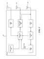
- FIG. 3 is a block diagram illustrating an example receiver 300 in accordance with an embodiment.
- the receiver 300 includes various components including control logic 310 , battery 320 , communication block 330 and associated antenna 370 , power meter 340 , rectifier 350 , beacon signal generator 360 and an associated antenna 380 , and switch 365 connecting the rectifier 350 or the beacon signal generator 360 to an associated antenna 390 .
- Some or all of the components can be omitted in some embodiments. Additional or fewer components are also possible.
- the rectifier 350 receives (via one or more client antennas) the power transmission signal from the power transmitter, which is fed through the power meter 340 to the battery 320 for charging.
- the power meter 340 measures the total received power signal strength and provides the control logic 310 with this measurement.
- the control logic 310 also may receive the battery power level from the battery 320 itself or receive battery power data from, e.g. an API of an operating system running on the receiver 300 .
- the control logic 310 may also transmit/receive via the communication block 330 a data signal on a data carrier frequency, such as the base signal clock for clock synchronization.
- the beacon signal generator 360 transmits the beacon signal, or calibration signal, using either the antenna 380 or 390 .
- the receiver may also receive its power directly from the rectifier 350 . This may be in addition to the rectifier 350 providing charging current to the battery 320 , or in lieu of providing charging. Also, it may be noted that the use of multiple antennas is one example of implementation and the structure may be reduced to one shared antenna, where the receiver multiplexes signal reception/transmission.
- An optional motion sensor 395 detects motion and signals the control logic 310 .
- a device when a device is receiving power at high frequencies above 500 MHz, its location may become a hotspot of (incoming) radiation. So when the device is on a person, the level of radiation may exceed a regulation or exceed acceptable radiation levels set by medical/industrial authorities.
- the device may integrate motion detection mechanisms such as accelerometers, assisted GPS, or other mechanisms. Once the device detects that it is in motion, the disclosed system assumes that it is being handled by a user, and signals the power transmitting array either to stop transmitting power to it, or to lower the received power to an acceptable fraction of the power. In cases where the device is used in a moving environment like a car, train or plane, the power might only be transmitted intermittently or at a reduced level unless the device is close to losing all available power.
- FIG. 4 is a system overview diagram illustrating various embodiments and components possible, though other combinations and variations are possible.
- the wireless power receiver can be in a form of an application specific integrated circuit (ASIC) chip, a mobile phone case, in a display device (e.g. computer monitor or television, which in turn may relay power to a nearby receiver 103 ), packaged within a standard battery form factor (e.g. AA battery), etc.
- ASIC application specific integrated circuit
- Techniques for calculating power consumption in wireless power delivery systems are disclosed herein. More specifically, techniques for calculating power consumption of devices, operating systems and applications are disclosed. For example, if multiple mobile phones having different operating systems are being charged via a wireless power delivery system, then the system can record power consumption of each individual mobile phone, the power consumption of each operating system running on each mobile phone, and the power consumption of each specific application running on each mobile phone. For example, a map application may consume more power if it is using GPS and a constant data connection to a website (versus an application that does not). Also, sometimes users may notice that their mobile phone runs out of charge more quickly than before but they would not know why. The techniques described herein may make it easier to pinpoint the cause, as well as provide other benefits.
- FIG. 5 is a diagram illustrating an example environment 500 including a cloud processing system 550 configured to calculate power consumption of wireless devices in power distribution areas 520 , according to various embodiments.
- the example environment 500 includes the cloud processing system 550 , a network 560 , multiple power distribution areas 520 , and multiple third party data consumers 510 .
- Each power distribution area 520 includes one or more wireless power transmitters or “chargers” 501 in communication with the network 560 and an administrator device (either locally or via network 560 ).
- the chargers 501 provide wireless power to various wireless devices as described herein.
- the cloud processing system 550 includes multiple servers 540 and data repositories 530 . Any number of servers 540 and/or data repositories 530 may be included with cloud processing system 550 .
- the cloud processing system 550 is configured to calculate power usage of wireless devices in each power distribution area 520 .
- the wireless devices can provide information to the chargers 501 through the use of software on the wireless devices that access APIs on the devices to gather the information.
- a charger 501 may transmit a periodic “Client Query” message to a client. This message requests the client to return a variety of information to the charger 501 .
- the Client Query message may be a ZigBee message.
- the wireless device may automatically transmit the information to the charger 501 periodically, or based on a trigger (e.g., when the battery level is below a threshold value, or when a rate of power consumption exceeds a threshold value).
- the information sent to the charger 501 may include a device manufacturer name or ID, device model, battery type/model, hardware, operating system, etc.
- the information may also include periodic updates on or status of applications currently running on the device, present battery status, device location, RF power received since last request, coulombs in or out of the battery since last request, device temperature, or other information related to power usage.
- the charger 501 receives this information and passes it along via network 560 to the cloud processing system 550 .
- the charger 501 includes local processing capabilities.
- the cloud processing system 550 or charger 501 then calculates power usage of the wireless devices based on the received information, including power usage based on particular hardware, operating system, application usage, etc.
- the cloud processing system 550 or charger 501 may utilize the wireless device's battery status (e.g., voltage and/or coulombs in/out) to calculate the power usage of the particular hardware.
- the cloud processing system 550 or charger 501 includes a database of types of batteries used in wireless devices, and their associated discharge/charge curves.
- the cloud processing system 550 or charger 501 may identify a particular discharge/charge curve from the information received from the wireless device (e.g., device ID, manufacturer/model number, etc.). The cloud processing system 550 or charger 501 may then identify where on the discharge/charge curve the device's present battery status falls, and from that calculate the time to charge or the time to die for that particular battery. The cloud processing system 550 or charger 501 may also track the percentage of time spent sending power to each wireless device, and from that calculate the amount of power that should be delivered to each wireless device.
- the cloud processing system 550 provides various information and alerts to a user and/or to a charger 501 . For example, if the power consumption of particular devices exceed a threshold, this might trigger an alert.
- the cloud processing system 550 can also provide recommendations regarding power consumption to a user and/or charger 501 , and/or the wireless device. For example, if the charger 501 scheduled a particular wireless device (“client 1”) to receive 75% of the available charge cycles over the last minute, but client 1 reports that more power was discharged from its battery than delivered into the battery, the cloud processing system 550 could report to the user to “move client 1 closer to the charger,” At the same time, charger 501 may dedicate more charging cycles to other wireless devices that may have a more effective power delivery.
- the third party data consumers 510 may be any entity that can utilize the collected wireless device information.
- the third party data consumers 510 can include telecommunications service providers, security service providers, home automation systems, energy companies, application developers (e.g., to optimize development across platforms, device manufacturers, etc.).
- the third party data consumers 510 can purchase and/or otherwise obtain rights to aggregated data from the cloud processing system 550 .
- a security service provider may utilize phase data included in the wireless device information to determine if there is motion in the power distribution area 520 (e.g., in lieu of access to motion sensor data).
- a home automation system may utilize temperature data included in the wireless device information to control a home thermostat.
- the network 560 may be any type of cellular, IP-based or converged telecommunications network, including but not limited to Global System for Mobile Communications (GSM), Time Division Multiple Access (TDMA), Code Division Multiple Access (CDMA), Orthogonal Frequency Division Multiple Access (OFDM), General Packet Radio Service (GPRS), Enhanced Data GSM Environment (EDGE), Advanced Mobile Phone System (AMPS), Worldwide Interoperability for Microwave Access (WiMAX), Universal Mobile Telecommunications System (UMTS), Evolution-Data Optimized (EVDO), Long Term Evolution (LTE), Ultra Mobile Broadband (UMB), Voice over Internet Protocol (VoIP), Unlicensed Mobile Access (UMA), etc.
- GSM Global System for Mobile Communications
- TDMA Time Division Multiple Access
- CDMA Code Division Multiple Access
- OFDM Orthogonal Frequency Division Multiple Access
- GPRS General Packet Radio Service
- EDGE Enhanced Data GSM Environment
- AMPS Advanced Mobile Phone System
- WiMAX Worldwide Interoperability for Microwave Access
- the network 560 can be any collection of distinct networks operating wholly or partially in conjunction to provide connectivity to the cloud processing system 550 , chargers 501 and third party data consumers 510 .
- communications to and from the cloud processing system 550 , chargers 501 and third party data consumers 510 can be achieved by an open network, such as the Internet, or a private network, such as an intranet and/or the extranet.
- the cloud processing system 550 , chargers 501 and third party data consumers 510 can be coupled to the network 560 (e.g., Internet) via a dial-up connection, a digital subscriber loop (DSL, ADSL), cable modem, wireless connections, direct fiber connections and/or any other types of connection.
- the network 560 e.g., Internet
- DSL digital subscriber loop
- ADSL digital subscriber loop
- wireless connections e.g., direct fiber connections and/or any other types of connection.
- the databases 530 can be implemented via object-oriented technology and/or via text files, and can be managed by any database management system. As shown, the databases 530 are coupled to (or otherwise included within cloud processing system 550 ). However, it is appreciated that in some embodiments, the databases 530 may be alternatively or additionally directly coupled to network 560 and/or distributed across multiple systems.
- the wireless device has installed a simple client application on its operating system (iOS, Android, etc.).
- the wireless device initially reports the device hardware information, the operating system device information, and/or the battery status to the charger 501 .
- the wireless device may receive a ZigBee message requesting the information, and may then return the information to the charger 501 .
- the wireless device may automatically provide the information to the charger 501 periodically or based on a trigger (e.g., when the battery level is below a threshold value, or when a rate of power consumption exceeds a threshold value).
- the wireless device may periodically update relevant information such as running applications, battery status, and location to the charger 501 .
- the charger 501 reports this information collected from the client to an admin interface of the cloud processing system 550 .
- An example of the admin interface of the cloud processing system 550 is shown in FIG. 6 .
- the admin interface 600 includes general charging details 615 for a selected wireless device.
- the general charging details include the selected wireless devices charging status (e.g., not charging, charging, fully charged) and the battery level of the selected wireless device.
- the admin interface 600 further includes voltage information 620 for a selected wireless device.
- the voltage information 620 includes RF voltage, the present battery voltage, and the net voltage. The voltage information 620 may plotted over time to show changes in the wireless device's voltage.
- the cloud processing system 550 sends information and alerts if power level consumption exceeds a threshold or usual/average value.
- the cloud processing system 550 may send the alerts to the wireless device, to the charger 501 , and/or as a notification in the admin interface.
- the alerts may be a visual notification on a display (e.g., a pop-up window), an audio notification (e.g., an alarm), or other type of notification.
- the cloud processing system 550 also can send recommendations regarding power usage based on previously collected information to the wireless device through the charger 501 .
- the wireless device user or the administrator may monitor the calculated power usage based on hardware, operating system, running apps, or other characteristics of the wireless device. This information may also be beneficial to 3rd party data consumers, such as telecommunication companies, energy companies, and application developers. For example, an application developer may utilize the power usage information to optimize application development across hardware platforms and operating systems.
- the techniques described herein solve the problem of enabling a charger system to calculate the power consumption requirements for hardware, operating systems and applications consistently across devices that are based on different platforms.
- operating systems such as iOS
- the techniques described herein are based on the operating system and client device itself, and not a centralized service, Thus, the techniques described herein provide the power usage information across different hardware, operating systems and applications.
- the cloud processing system 550 or charger 501 may calculate the power usage information for devices, operating systems, and/or applications.
- this power usage information is useful for owners of the charger 501 and for owners of the wireless devices so they are aware of the cost incurred and the battery life length for the wireless devices.
- This power usage information could also be useful for other providers and software developers as a way to optimize hardware and software energy consumption.
- measuring power consumption and application usage at such a granular level and at such a global scale may be leveraged to uncover trends. For example, if power consumption increases across many wireless devices at one time, this could be an indication of a specific event many user are experiencing. For example, if the power consumption for a specific application (e.g., a weather application) increases for many wireless devices, this could mean that users are experiencing an issue with that application (e.g., a major weather issue).
- a specific application e.g., a weather application
- the same power usage information is useful for understanding usage habits of users which allows for customizing services and providing more targeted advertising. For example, if a user's battery performance starts degrading, it is possible to notify them that it is time to change the battery and to recommend a battery that meets his or her needs.
- FIGS. 7A and 7B are flow diagrams illustrating example processes 700 A and 700 B, respectively, facilitating calculation of power consumption of wireless devices, according to various embodiments.
- An application and/or software module having instructions included therein can be executed by one or more processors of the wireless device to cause the wireless device, in conjunction with a power receiver client such as, for example, client 103 of FIG. 1 , to perform the example process 700 A.
- the wireless device can be any wireless device such as, for example, wireless device 102 of FIG. 1 .
- An application and/or software module having instructions included therein can be executed by one or more processors of a cloud processing system such as, for example, cloud processing system 550 of FIG. 5 , directing the cloud processing system to perform the example process 700 B.
- process 700 A illustrates a flow diagram showing an example process 700 A facilitating calculation of power consumption of a wireless device in a wireless power delivery environment, according to an embodiment.
- the wireless device accesses one or more Application Program Interfaces (APIs) on the wireless device to gather information related to the wireless device.
- APIs Application Program Interfaces
- the information can include a device manufacturer name or ID, device model, battery type/model, hardware, operating system, attached devices (e.g., wirelessly connected keyboard/mouse), etc.
- the information can also include periodic updates on applications currently running or executing on the wireless device, current battery level of the primary battery of the wireless device, the wireless device's current/past locations, etc.
- the wireless device monitors the applications executing on the wireless device (e.g., those applications that are running or have a footprint in RAM).
- the wireless device determines if a trigger is detected.
- the trigger can be configured to occur periodically. Alternatively or additionally, the trigger can occur if, for example, a threshold level of power is crossed (either the power dips below low power threshold or power increases to or above upper power threshold).
- the wireless device gathers power information about the wireless device and, at process 718 A, provides the power information to a charger.
- process 700 B illustrates a flow diagram showing an example process 700 B facilitating calculation of power consumption of a wireless device in a wireless power delivery environment, according to an embodiment.
- a wireless charger receives power information from a wireless device and transfers the information to a cloud processing system.
- a cloud processing system As discussed above, some or all of the processes or steps discussed can alternatively or additionally be performed by a charger in other embodiments.
- the cloud processing system receives the information associated with the wireless device.
- the cloud processing system calculates power usage of the client based on the information. The power usage may be calculated based on a discharge/charge curve for the particular battery in the wireless device, as described above.
- the cloud processing system determines if a trigger has been detected.
- the trigger can be configured to occur periodically. Alternatively or additionally, the trigger can occur if, for example, a threshold level of power is crossed (either the power dips below low power threshold or power increases to or above upper power threshold).
- the cloud processing system responsively provides power usage information corresponding to the wireless device to an administer and, at process 718 B, to the charger.
- the administrator may use the power usage information to detect problems with the charging of wireless devices. For example, if power delivery from a charger to all its associated wireless devices drops over time, the administrator may be able to determine whether something is wrong with that particular charger, or whether something in the charger's environment has changed.
- the process may also branch at process 712 B to process 720 E where the cloud processing system aggregates data received from multiple devices and, at process 722 B, processes the data to identify various trends across geographies, chargers, environments, devices, etc.
- the cloud processing system provides the aggregated data and or the trend data to a data consumer such as, for example, a 3rd party data consumer 510 .
- the data consumer may provide use the aggregated data to provide additional services for the administrator or the users of the wireless devices. For example, if the aggregated data indicates that 100% allocation of power delivery cycles can't keep up with the charge needs of the wireless devices, the data consumer may offer a larger or second charger to the administrator of the charger.
- FIG. 8 depicts a block diagram illustrating example components of a representative client (e.g., mobile device, tablet computer, category controller, maintenance controller, etc.) 800 in the form of a mobile (or smart) phone or tablet computer device.
- a representative client e.g., mobile device, tablet computer, category controller, maintenance controller, etc.
- FIG. 8 depicts a block diagram illustrating example components of a representative client (e.g., mobile device, tablet computer, category controller, maintenance controller, etc.) 800 in the form of a mobile (or smart) phone or tablet computer device.
- Various interfaces and modules are shown with reference to FIG. 8 , however, the mobile device or tablet computer does not require all of modules or functions for performing the functionality described herein.
- various components are not included and/or necessary for operation of the category controller.
- components such as GPS radios, cellular radios, and accelerometers may not be included in the controllers to reduce costs and/or complexity.
- components such as ZigBeeTM radios and RFID transceivers
- FIG. 9 depicts a diagrammatic representation of a machine, in the example form, of a computer system 900 within which a set of instructions, for causing the machine to perform any one or more of the methodologies discussed herein, may be executed.
- the computer system 900 can be representative of any computer system, server, etc., described herein.
- the computer system 900 includes a processor (CPU), memory, non-volatile memory, and an interface device. Various common components (e.g., cache memory) are omitted for illustrative simplicity.
- the computer system 900 is intended to illustrate a hardware device on which any of the components depicted in the example of FIG. 1 (and any other components described in this specification) can be implemented.
- the computer system 900 can be of any applicable known or convenient type.
- the components of the computer system 900 can be coupled together via a bus or through some other known or convenient device.
- the processor may be, for example, a conventional microprocessor such as an Intel x86-based microprocessor.
- Intel x86-based microprocessor an Intel x86-based microprocessor.
- machine-readable (storage) medium or “computer-readable (storage) medium” includes any type of device that is accessible by the processor.
- the memory is coupled to the processor by, for example, a bus.
- the memory can include, by way of example but not limitation, random access memory (RAM), such as dynamic RAM (DRAM), static RAM (SRAM), flash RAM, etc.
- RAM random access memory
- DRAM dynamic RAM
- SRAM static RAM
- flash RAM etc.
- the memory can be local, remote, or distributed.
- the bus also couples the processor to the non-volatile memory and drive unit.
- the non-volatile memory is often a magnetic floppy or hard disk, a magnetic-optical disk, an optical disk, a read-only memory (ROM), such as a CD-ROM, EPROM, or EEPROM, a magnetic or optical card, or another form of storage for large amounts of data. Some of this data is often written, by a direct memory access process, into memory during execution of software in the computer 13 .
- the non-volatile storage can be local, remote, or distributed.
- the non-volatile memory is optional because systems can be created with all applicable data available in memory.
- a typical computer system will usually include at least a processor, memory, and a device (e.g., a bus) coupling the memory to the processor.
- Software is typically stored in the non-volatile memory and/or the drive unit. Indeed, for large programs, it may not even be possible to store the entire program in the memory. Nevertheless, it should be understood that for software to run, if necessary, it is moved to a computer readable location appropriate for processing, and for illustrative purposes, that location is referred to as the memory herein. Even when software is moved to the memory for execution, the processor will typically make use of hardware registers to store values associated with the software, and local cache that, ideally, serves to speed up execution.
- a software program is assumed to be stored at any known or convenient location (from non-volatile storage to hardware registers) when the software program is referred to as “implemented in a computer-readable medium.”
- a processor is considered to be “configured to execute a program” when at least one value associated with the program is stored in a register readable by the processor.
- the bus also couples the processor to the network interface device.
- the interface can include one or more of a modem or network interface. It will be appreciated that a modem or network interface can be considered to be part of the computer system.
- the interface can include an analog modem, ISDN modem, cable modem, token ring interface, satellite transmission interface (e.g. “direct PC”), or other interfaces for coupling a computer system to other computer systems.
- the interface can include one or more input and/or output devices.
- the I/O devices can include, by way of example but not limitation, a keyboard, a mouse or other pointing device, disk drives, printers, a scanner, and other input and/or output devices, including a display device.
- the display device can include, by way of example but not limitation, a liquid crystal display (LCD), OLED, or some other applicable known or convenient display device. For simplicity, it is assumed that controllers of any devices not depicted reside in the interface.
- the computer system 1300 can be controlled by operating system software that includes a file management system, such as a disk operating system.
- operating system software with associated file management system software is the family of operating systems known as Windows® from Microsoft Corporation of Redmond, Wash., and their associated file management systems.
- Windows® from Microsoft Corporation of Redmond, Wash.
- Windows® is the family of operating systems known as Windows® from Microsoft Corporation of Redmond, Wash.
- Linux operating system is the Linux operating system and its associated file management system.
- the file management system is typically stored in the non-volatile memory and/or drive unit and causes the processor to execute the various acts required by the operating system to input and output data and to store data in the memory, including storing files on the non-volatile memory and/or drive unit.
- the machine operates as a standalone device or may be connected (e.g., networked) to other machines.
- the machine may operate in the capacity of a server or a client machine in a client-server network environment or as a peer machine in a peer-to-peer (or distributed) network environment).
- the machine may be a server computer, a client computer, a personal computer (PC), a tablet PC, a laptop computer, a set-top box (STB), a personal digital assistant (PDA), a cellular telephone, a smart phone a processor, a telephone, a web appliance, a network router, switch or bridge, or any machine capable of executing a set of instructions (sequential or otherwise) that specify actions to be taken by that machine.
- PC personal computer
- PDA personal digital assistant
- machine-readable medium or machine-readable storage medium is shown in an exemplary embodiment to be a single medium, the term “machine-readable medium” and “machine-readable storage medium” should be taken to include a single medium or multiple media (e.g., a centralized or distributed database, and/or associated caches and servers) that store the one or more sets of instructions.
- the term “machine-readable medium” and “machine-readable storage medium” shall also be taken to include any medium that is capable of storing, encoding or carrying a set of instructions for execution by the machine and that cause the machine to perform any one or more of the methodologies of the presently disclosed technique and innovation.
- machine-readable storage media machine-readable media, or computer-readable (storage) media
- recordable type media such as volatile and non-volatile memory devices, floppy and other removable disks, hard disk drives, optical disks (e.g., Compact Disk Read-Only Memory (CD ROMS), Digital Versatile Disks, (DVDs), etc.), among others, and transmission type media such as digital and analog communication links.
- CD ROMS Compact Disk Read-Only Memory
- DVDs Digital Versatile Disks
- transmission type media such as digital and analog communication links.
- the words “comprise,” “comprising,” and the like are to be construed in an inclusive sense, as opposed to an exclusive or exhaustive sense; that is to say, in the sense of “including, but not limited to.”
- the terms “connected,” “coupled,” or any variant thereof means any connection or coupling, either direct or indirect, between two or more elements; the coupling of connection between the elements can be physical, logical, or a combination thereof.
- the words “herein,” “above,” “below,” and words of similar import when used in this application, shall refer to this application as a whole and not to any particular portions of this application.
- words in the above Detailed Description using the singular or plural number may also include the plural or singular number respectively.
- the word “or,” in reference to a list of two or more items, covers all of the following interpretations of the word: any of the items in the list, all of the items in the list, and any combination of the items in the list.
Abstract
Description
Claims (20)
Priority Applications (4)
| Application Number | Priority Date | Filing Date | Title |
|---|---|---|---|
| US15/094,952 US9632554B2 (en) | 2015-04-10 | 2016-04-08 | Calculating power consumption in wireless power delivery systems |
| US15/094,963 US9620996B2 (en) | 2015-04-10 | 2016-04-08 | Wireless charging with multiple power receiving facilities on a wireless device |
| US15/461,121 US20170187249A1 (en) | 2015-04-10 | 2017-03-16 | Wireless Charging With Multiple Power Receiving Facilities On A Wireless Device |
| US15/461,080 US10574081B2 (en) | 2015-04-10 | 2017-03-16 | Calculating power consumption in wireless power delivery systems |
Applications Claiming Priority (16)
| Application Number | Priority Date | Filing Date | Title |
|---|---|---|---|
| US201562146233P | 2015-04-10 | 2015-04-10 | |
| US201562163964P | 2015-05-19 | 2015-05-19 | |
| US14/926,014 US9490875B2 (en) | 2014-10-31 | 2015-10-29 | Techniques for filtering multi-component signals |
| US201562256694P | 2015-11-17 | 2015-11-17 | |
| US14/945,741 US9971015B2 (en) | 2015-04-10 | 2015-11-19 | Techniques for imaging wireless power delivery environments and tracking objects therein |
| US14/945,783 US10825417B2 (en) | 2015-04-10 | 2015-11-19 | Wirelessly powered electronic display apparatuses |
| US14/956,673 US9961705B2 (en) | 2014-12-02 | 2015-12-02 | Techniques for encoding beacon signals in wireless power delivery environments |
| US15/048,982 US10559971B2 (en) | 2015-04-10 | 2016-02-19 | Wirelessly chargeable battery apparatus |
| US15/048,984 US10079494B2 (en) | 2015-04-10 | 2016-02-19 | Removably attachable portable device apparatus with integrated wireless power receiving facilities |
| US15/092,026 US10193397B2 (en) | 2015-04-10 | 2016-04-06 | Establishing connections with chargers in multi-charger wireless power delivery environments |
| US15/091,986 US10177607B2 (en) | 2015-04-10 | 2016-04-06 | Techniques for delivering retrodirective wireless power |
| US15/093,023 US10223999B2 (en) | 2015-04-10 | 2016-04-07 | Techniques for statically tuning retro-directive wireless power transmission systems |
| US15/094,952 US9632554B2 (en) | 2015-04-10 | 2016-04-08 | Calculating power consumption in wireless power delivery systems |
| US15/094,079 US10256670B2 (en) | 2015-04-10 | 2016-04-08 | Wireless power transceivers for supplementing wireless power delivery and extending range |
| US15/094,963 US9620996B2 (en) | 2015-04-10 | 2016-04-08 | Wireless charging with multiple power receiving facilities on a wireless device |
| US15/093,868 US10037743B2 (en) | 2015-04-10 | 2016-04-08 | Inferring battery status of an electronic device in a wireless power delivery environment |
Related Child Applications (1)
| Application Number | Title | Priority Date | Filing Date |
|---|---|---|---|
| US15/461,080 Continuation US10574081B2 (en) | 2015-04-10 | 2017-03-16 | Calculating power consumption in wireless power delivery systems |
Publications (2)
| Publication Number | Publication Date |
|---|---|
| US20160299549A1 US20160299549A1 (en) | 2016-10-13 |
| US9632554B2 true US9632554B2 (en) | 2017-04-25 |
Family
ID=57111745
Family Applications (2)
| Application Number | Title | Priority Date | Filing Date |
|---|---|---|---|
| US15/094,952 Active US9632554B2 (en) | 2015-04-10 | 2016-04-08 | Calculating power consumption in wireless power delivery systems |
| US15/461,080 Active US10574081B2 (en) | 2015-04-10 | 2017-03-16 | Calculating power consumption in wireless power delivery systems |
Family Applications After (1)
| Application Number | Title | Priority Date | Filing Date |
|---|---|---|---|
| US15/461,080 Active US10574081B2 (en) | 2015-04-10 | 2017-03-16 | Calculating power consumption in wireless power delivery systems |
Country Status (1)
| Country | Link |
|---|---|
| US (2) | US9632554B2 (en) |
Cited By (4)
| Publication number | Priority date | Publication date | Assignee | Title |
|---|---|---|---|---|
| US20160020637A1 (en) * | 2014-07-15 | 2016-01-21 | Rf Micro Devices, Inc. | Wireless charging circuit |
| US20160079799A1 (en) * | 2014-09-16 | 2016-03-17 | Rf Micro Devices, Inc. | Method for wireless charging power control |
| US20170373522A1 (en) * | 2016-06-23 | 2017-12-28 | Apple Inc. | Charging System |
| CN109600771A (en) * | 2018-11-26 | 2019-04-09 | 清华大学 | A kind of across the protocol communication method and device of WiFi equipment to ZigBee equipment |
Families Citing this family (11)
| Publication number | Priority date | Publication date | Assignee | Title |
|---|---|---|---|---|
| US10708842B2 (en) * | 2016-01-13 | 2020-07-07 | Locus Control LLC | Low power communications system |
| TWI679826B (en) | 2016-06-10 | 2019-12-11 | 美商歐西亞股份有限公司 | Method and apparatus for wireless power transmission for near and far field applications |
| US10277078B2 (en) | 2017-02-01 | 2019-04-30 | Ossia Inc. | Central controller board enhancements for wireless power battery charging systems |
| US10425131B2 (en) | 2017-04-06 | 2019-09-24 | Ossia Inc. | Beacon localization for a client device in wireless environment applications |
| US9942788B1 (en) | 2017-05-19 | 2018-04-10 | Ossia Inc. | Systems and methods for determining operational status of functional components of a wireless signal transmission environment |
| US11188095B1 (en) * | 2017-07-31 | 2021-11-30 | AI Incorporated | Systems and methods for sending scheduling information to a robotic device |
| US10554796B2 (en) * | 2017-11-01 | 2020-02-04 | Western Digital Technologies, Inc. | Memory station for automatically backing up data and charging mobile devices |
| KR20230145212A (en) * | 2017-11-08 | 2023-10-17 | 오시아 인크. | Anytime beaconing in a wireless power transmission system |
| EP3711374B1 (en) * | 2017-11-17 | 2021-12-01 | Telit Communications S.P.A. | Fast energy counter for wireless communication transceiver |
| CN110913504B (en) * | 2019-11-07 | 2022-03-08 | Oppo(重庆)智能科技有限公司 | Network connection method, terminal device and storage medium |
| JP2023112458A (en) | 2022-02-01 | 2023-08-14 | 豊田合成株式会社 | Power transmission device |
Citations (73)
| Publication number | Priority date | Publication date | Assignee | Title |
|---|---|---|---|---|
| US3989994A (en) | 1974-08-09 | 1976-11-02 | Raytheon Company | Space oriented microwave power transmission system |
| US4257050A (en) | 1978-02-16 | 1981-03-17 | George Ploussios | Large element antenna array with grouped overlapped apertures |
| US4361892A (en) | 1980-11-03 | 1982-11-30 | Bell Telephone Laboratories, Incorporated | Adaptive equalizer |
| US4685047A (en) | 1986-07-16 | 1987-08-04 | Phillips Raymond P Sr | Apparatus for converting radio frequency energy to direct current |
| US4779097A (en) | 1985-09-30 | 1988-10-18 | The Boeing Company | Segmented phased array antenna system with mechanically movable segments |
| US5000037A (en) | 1989-11-30 | 1991-03-19 | The Boeing Company | Gauging apparatus and method |
| US5218374A (en) | 1988-09-01 | 1993-06-08 | Apti, Inc. | Power beaming system with printer circuit radiating elements having resonating cavities |
| US5223781A (en) | 1983-07-13 | 1993-06-29 | Criswell David R | Power collection and transmission system and method |
| US5400037A (en) | 1991-05-31 | 1995-03-21 | East; Thomas W. R. | Self-focusing antenna array |
| JPH07236204A (en) | 1994-02-22 | 1995-09-05 | Hitachi Ltd | Method and system for charging electric automobile |
| US5486833A (en) | 1993-04-02 | 1996-01-23 | Barrett; Terence W. | Active signalling systems |
| JPH0837743A (en) | 1994-07-22 | 1996-02-06 | Nissan Motor Co Ltd | Microwave transmitting device |
| US5503350A (en) | 1993-10-28 | 1996-04-02 | Skysat Communications Network Corporation | Microwave-powered aircraft |
| JPH08103039A (en) | 1994-09-30 | 1996-04-16 | Mitsubishi Electric Corp | Radio wave feeder apparatus |
| JPH08130840A (en) | 1994-11-01 | 1996-05-21 | Mitsubishi Electric Corp | Radio wave feeder device |
| US5733313A (en) | 1996-08-01 | 1998-03-31 | Exonix Corporation | RF coupled, implantable medical device with rechargeable back-up power source |
| US6114834A (en) | 1997-05-09 | 2000-09-05 | Parise; Ronald J. | Remote charging system for a vehicle |
| US6127799A (en) | 1999-05-14 | 2000-10-03 | Gte Internetworking Incorporated | Method and apparatus for wireless powering and recharging |
| WO2001003438A2 (en) | 1999-07-02 | 2001-01-11 | The Trustees Of Columbia University In The City Ofnew York | Mobile and hand-held broadcast video earth station terminals and methods for communicating with earth terminals via satellites |
| JP2002084685A (en) | 2000-09-07 | 2002-03-22 | Univ Kyoto | Rectenna and method for increasing rectenna power |
| US20020057219A1 (en) | 2000-06-16 | 2002-05-16 | Shuichi Obayashi | Adaptive array antenna |
| JP2002152995A (en) | 2000-11-10 | 2002-05-24 | Toyota Motor Corp | Electrical power receiving and supplying system |
| US6474341B1 (en) | 1999-10-28 | 2002-11-05 | Surgical Navigation Technologies, Inc. | Surgical communication and power system |
| US6615074B2 (en) | 1998-12-22 | 2003-09-02 | University Of Pittsburgh Of The Commonwealth System Of Higher Education | Apparatus for energizing a remote station and related method |
| US6621470B1 (en) | 2001-03-23 | 2003-09-16 | Northrop Grumman Corporation | Tiled phased array antenna |
| US6690324B2 (en) | 2000-12-12 | 2004-02-10 | Harris Corporation | Phased array antenna having reduced beam settling times and related methods |
| US6700538B1 (en) | 2000-03-29 | 2004-03-02 | Time Domain Corporation | System and method for estimating separation distance between impulse radios using impulse signal amplitude |
| US6721159B2 (en) | 2000-09-04 | 2004-04-13 | Tsubakimoto Chain Co. | Power feeding apparatus, transporter and transport system |
| US6738017B2 (en) | 2002-08-06 | 2004-05-18 | Lockheed Martin Corporation | Modular phased array with improved beam-to-beam isolation |
| US20040140929A1 (en) | 2002-12-27 | 2004-07-22 | Takeshi Toda | Adaptive array antenna controller |
| JP2004229427A (en) | 2003-01-23 | 2004-08-12 | Toyota Motor Corp | Transportation system using energy |
| US6856291B2 (en) | 2002-08-15 | 2005-02-15 | University Of Pittsburgh- Of The Commonwealth System Of Higher Education | Energy harvesting circuits and associated methods |
| US6882128B1 (en) | 2000-09-27 | 2005-04-19 | Science Applications International Corporation | Method and system for energy reclamation and reuse |
| JP2005261187A (en) | 2004-02-12 | 2005-09-22 | Kansai Tlo Kk | Wireless power supply system |
| KR20050096068A (en) | 2004-03-29 | 2005-10-05 | 주식회사 한림포스텍 | Non-contact battery charging system possible multi-charging and core block design method for it |
| US6967462B1 (en) | 2003-06-05 | 2005-11-22 | Nasa Glenn Research Center | Charging of devices by microwave power beaming |
| US7068991B2 (en) | 1997-05-09 | 2006-06-27 | Parise Ronald J | Remote power recharge for electronic equipment |
| US7084605B2 (en) | 2003-10-29 | 2006-08-01 | University Of Pittsburgh | Energy harvesting circuit |
| US20060224489A1 (en) | 2005-03-30 | 2006-10-05 | Pantelis Thomas L | Method and system for providing displays of securities trading information |
| KR100654623B1 (en) | 2005-10-12 | 2006-12-08 | 인하대학교 산학협력단 | Poality-averaged dipole rectennas array system for improving microwave power coupling performance in wireless electrical power transmission |
| JP2007022382A (en) | 2005-07-19 | 2007-02-01 | Mitsubishi Electric Corp | Feeding system to flying object, power transmission device to flying object used therefor, and flying object |
| KR20070055086A (en) | 2005-11-25 | 2007-05-30 | 엘에스전선 주식회사 | Apparatus for wireless charging having multi-charge cell and method for controlling the same |
| US20070142061A1 (en) | 2005-12-20 | 2007-06-21 | Taubenheim David B | Method and apparatus for determining the location of a node in a wireless network |
| US20080014897A1 (en) | 2006-01-18 | 2008-01-17 | Cook Nigel P | Method and apparatus for delivering energy to an electrical or electronic device via a wireless link |
| US20080028239A1 (en) * | 2006-07-31 | 2008-01-31 | Motorola, Inc. | System for managing the power source life between multiple individually powered devices in a wired system and method of using same |
| US20080042847A1 (en) | 2006-08-14 | 2008-02-21 | Allen Hollister | Method for reading RFID tags using directional antennas |
| US20080122297A1 (en) | 2006-11-24 | 2008-05-29 | Semiconductor Energy Laboratory Co., Ltd. | Wireless Power Supply System and Wireless Power Supply Method |
| US20080217551A1 (en) * | 2007-03-08 | 2008-09-11 | Chong Zhang | Real time radiation monitoring system and portable telepositional radiation dosimeter |
| US20080227478A1 (en) | 2007-03-15 | 2008-09-18 | Greene Charles E | Multiple frequency transmitter, receiver, and systems thereof |
| US20080311961A1 (en) * | 2004-12-24 | 2008-12-18 | Telecom Italia S.P.A. | Network Call Management in Case of Low Battery Condition of Mobile Communications Terminals |
| WO2008156571A2 (en) | 2007-06-14 | 2008-12-24 | Hatem Zeine | Wireless power transmission system |
| US20090284220A1 (en) | 2008-05-13 | 2009-11-19 | Qualcomm Incorporated | Method and apparatus for adaptive tuning of wireless power transfer |
| US20100033021A1 (en) | 2008-08-05 | 2010-02-11 | Broadcom Corporation | Phased array wireless resonant power delivery system |
| US20100133920A1 (en) | 2005-07-12 | 2010-06-03 | Joannopoulos John D | Wireless energy transfer across a distance to a moving device |
| US20100142509A1 (en) | 2008-12-08 | 2010-06-10 | Samsung Electronics Co., Ltd. | Method and system for integrated wireless power and data communication |
| US7744032B2 (en) | 2007-04-27 | 2010-06-29 | Lockheed Martin Corporation | Power and imaging system for an airship |
| US20100222010A1 (en) | 2009-02-13 | 2010-09-02 | Qualcomm Incorporated | Antenna sharing for wirelessly powered devices |
| US20100315045A1 (en) | 2007-06-14 | 2010-12-16 | Omnilectric, Inc. | Wireless power transmission system |
| US20110156640A1 (en) | 2009-12-25 | 2011-06-30 | Mehran Moshfeghi | Method and apparatus for wirelessly transferring power and communicating with one or more slave devices |
| KR20110088100A (en) | 2010-01-28 | 2011-08-03 | 주식회사 팬택 | System, mobile station, management server and wireless power transfer for transmitting/receiving wireless power |
| US20110225073A1 (en) * | 2010-03-12 | 2011-09-15 | Samsung Electronics Co., Ltd. | Apparatus and method for performing wireless charging |
| US20120176227A1 (en) | 2011-01-12 | 2012-07-12 | Intermec Ip Corp. | Method and apparatus to mitigate multipath in rfid |
| US20120220350A1 (en) | 2009-02-26 | 2012-08-30 | Research In Motion Limited | Method and Apparatus for Dynamic Battery Management Control in a Mobile Communication Device |
| US20130201316A1 (en) * | 2012-01-09 | 2013-08-08 | May Patents Ltd. | System and method for server based control |
| US20140004912A1 (en) | 2012-06-28 | 2014-01-02 | Broadcom Corporation | Coordinated Wireless Communication and Power Delivery |
| US20140009108A1 (en) | 2012-07-06 | 2014-01-09 | DvineWave Inc. | Transmitters for wireless power transmission |
| US20140171107A1 (en) | 2012-12-19 | 2014-06-19 | Industrial Technology Research Institute | System and method for wireless indoor localization based on inertial measurement unit and map information |
| US20140266034A1 (en) | 2013-03-14 | 2014-09-18 | Robert Bosch Gmbh | Short Distance Wireless Device Charging System having a Shared Antenna |
| US20140368053A1 (en) * | 2012-01-25 | 2014-12-18 | Lg Electronics Inc. | Method and apparatus for setting frequency of wireless power transmission |
| US20150038079A1 (en) | 2013-07-30 | 2015-02-05 | Samsung Electro-Mechanics Co., Ltd. | Device for wireless communication and method for wireless communication |
| US20150042526A1 (en) | 2013-02-04 | 2015-02-12 | Ossia, Inc. | High dielectric antenna array |
| JP2015050719A (en) | 2013-09-03 | 2015-03-16 | Kddi株式会社 | Portable type information apparatus for reading out predetermined information from charger, system, program, and method |
| WO2016019362A1 (en) | 2014-07-31 | 2016-02-04 | Ossia, Inc. | Techniques for determining distance between radiating objects in multipath wireless power delivery environments |
Family Cites Families (13)
| Publication number | Priority date | Publication date | Assignee | Title |
|---|---|---|---|---|
| CN2666013Y (en) | 2003-10-31 | 2004-12-22 | 宏碁股份有限公司 | Non-contact inductive charger for hand-held device |
| US8111042B2 (en) | 2008-08-05 | 2012-02-07 | Broadcom Corporation | Integrated wireless resonant power charging and communication channel |
| US8760113B2 (en) | 2009-02-24 | 2014-06-24 | Qualcomm Incorporated | Wireless power charging timing and charging control |
| KR101428901B1 (en) | 2010-04-13 | 2014-08-08 | 후지쯔 가부시끼가이샤 | Power supply system, power transmitter, and power receiver |
| CN102347640B (en) | 2011-06-09 | 2013-09-18 | 东南大学 | Wireless energy transmission device |
| JP2013026813A (en) | 2011-07-21 | 2013-02-04 | Sharp Corp | Apparatus information acquisition system |
| KR101253670B1 (en) | 2011-09-05 | 2013-04-11 | 엘에스전선 주식회사 | Apparatus for wireless power transmission using multi antenna and Method for controlling thereof |
| US9363754B2 (en) | 2012-08-17 | 2016-06-07 | Apple Inc. | Managing power consumption in mobile devices |
| JP6126373B2 (en) | 2012-12-13 | 2017-05-10 | パナソニック株式会社 | Wireless module and wireless communication device |
| CA2902796C (en) | 2013-02-28 | 2022-08-16 | Powermat Technologies Ltd. | Systems and methods for managing a distributed wireless power transfer network for electrical devices |
| JP6172263B2 (en) | 2013-03-26 | 2017-08-02 | 富士通株式会社 | Wireless power transmission system and wireless power transmission method |
| EP3033817B1 (en) | 2013-08-15 | 2019-10-09 | Humavox Ltd. | Wireless charging device |
| CN104360270A (en) | 2014-10-22 | 2015-02-18 | 成都西可科技有限公司 | Battery charging curve acquiring device and method of portable electronic equipment |
-
2016
- 2016-04-08 US US15/094,952 patent/US9632554B2/en active Active
-
2017
- 2017-03-16 US US15/461,080 patent/US10574081B2/en active Active
Patent Citations (84)
| Publication number | Priority date | Publication date | Assignee | Title |
|---|---|---|---|---|
| US3989994A (en) | 1974-08-09 | 1976-11-02 | Raytheon Company | Space oriented microwave power transmission system |
| US4257050A (en) | 1978-02-16 | 1981-03-17 | George Ploussios | Large element antenna array with grouped overlapped apertures |
| US4361892A (en) | 1980-11-03 | 1982-11-30 | Bell Telephone Laboratories, Incorporated | Adaptive equalizer |
| US5223781A (en) | 1983-07-13 | 1993-06-29 | Criswell David R | Power collection and transmission system and method |
| US4779097A (en) | 1985-09-30 | 1988-10-18 | The Boeing Company | Segmented phased array antenna system with mechanically movable segments |
| US4685047A (en) | 1986-07-16 | 1987-08-04 | Phillips Raymond P Sr | Apparatus for converting radio frequency energy to direct current |
| US5218374A (en) | 1988-09-01 | 1993-06-08 | Apti, Inc. | Power beaming system with printer circuit radiating elements having resonating cavities |
| US5000037A (en) | 1989-11-30 | 1991-03-19 | The Boeing Company | Gauging apparatus and method |
| US5400037A (en) | 1991-05-31 | 1995-03-21 | East; Thomas W. R. | Self-focusing antenna array |
| US5486833A (en) | 1993-04-02 | 1996-01-23 | Barrett; Terence W. | Active signalling systems |
| US5503350A (en) | 1993-10-28 | 1996-04-02 | Skysat Communications Network Corporation | Microwave-powered aircraft |
| JPH07236204A (en) | 1994-02-22 | 1995-09-05 | Hitachi Ltd | Method and system for charging electric automobile |
| JPH0837743A (en) | 1994-07-22 | 1996-02-06 | Nissan Motor Co Ltd | Microwave transmitting device |
| JPH08103039A (en) | 1994-09-30 | 1996-04-16 | Mitsubishi Electric Corp | Radio wave feeder apparatus |
| JPH08130840A (en) | 1994-11-01 | 1996-05-21 | Mitsubishi Electric Corp | Radio wave feeder device |
| US5733313A (en) | 1996-08-01 | 1998-03-31 | Exonix Corporation | RF coupled, implantable medical device with rechargeable back-up power source |
| US6114834A (en) | 1997-05-09 | 2000-09-05 | Parise; Ronald J. | Remote charging system for a vehicle |
| US7068991B2 (en) | 1997-05-09 | 2006-06-27 | Parise Ronald J | Remote power recharge for electronic equipment |
| US6615074B2 (en) | 1998-12-22 | 2003-09-02 | University Of Pittsburgh Of The Commonwealth System Of Higher Education | Apparatus for energizing a remote station and related method |
| US6127799A (en) | 1999-05-14 | 2000-10-03 | Gte Internetworking Incorporated | Method and apparatus for wireless powering and recharging |
| WO2001003438A2 (en) | 1999-07-02 | 2001-01-11 | The Trustees Of Columbia University In The City Ofnew York | Mobile and hand-held broadcast video earth station terminals and methods for communicating with earth terminals via satellites |
| US6474341B1 (en) | 1999-10-28 | 2002-11-05 | Surgical Navigation Technologies, Inc. | Surgical communication and power system |
| US6700538B1 (en) | 2000-03-29 | 2004-03-02 | Time Domain Corporation | System and method for estimating separation distance between impulse radios using impulse signal amplitude |
| US20020057219A1 (en) | 2000-06-16 | 2002-05-16 | Shuichi Obayashi | Adaptive array antenna |
| US6721159B2 (en) | 2000-09-04 | 2004-04-13 | Tsubakimoto Chain Co. | Power feeding apparatus, transporter and transport system |
| JP2002084685A (en) | 2000-09-07 | 2002-03-22 | Univ Kyoto | Rectenna and method for increasing rectenna power |
| US6882128B1 (en) | 2000-09-27 | 2005-04-19 | Science Applications International Corporation | Method and system for energy reclamation and reuse |
| JP2002152995A (en) | 2000-11-10 | 2002-05-24 | Toyota Motor Corp | Electrical power receiving and supplying system |
| US6690324B2 (en) | 2000-12-12 | 2004-02-10 | Harris Corporation | Phased array antenna having reduced beam settling times and related methods |
| US6621470B1 (en) | 2001-03-23 | 2003-09-16 | Northrop Grumman Corporation | Tiled phased array antenna |
| US6738017B2 (en) | 2002-08-06 | 2004-05-18 | Lockheed Martin Corporation | Modular phased array with improved beam-to-beam isolation |
| US6856291B2 (en) | 2002-08-15 | 2005-02-15 | University Of Pittsburgh- Of The Commonwealth System Of Higher Education | Energy harvesting circuits and associated methods |
| US20040140929A1 (en) | 2002-12-27 | 2004-07-22 | Takeshi Toda | Adaptive array antenna controller |
| JP2004229427A (en) | 2003-01-23 | 2004-08-12 | Toyota Motor Corp | Transportation system using energy |
| US6967462B1 (en) | 2003-06-05 | 2005-11-22 | Nasa Glenn Research Center | Charging of devices by microwave power beaming |
| US7084605B2 (en) | 2003-10-29 | 2006-08-01 | University Of Pittsburgh | Energy harvesting circuit |
| JP2005261187A (en) | 2004-02-12 | 2005-09-22 | Kansai Tlo Kk | Wireless power supply system |
| KR20050096068A (en) | 2004-03-29 | 2005-10-05 | 주식회사 한림포스텍 | Non-contact battery charging system possible multi-charging and core block design method for it |
| US20080311961A1 (en) * | 2004-12-24 | 2008-12-18 | Telecom Italia S.P.A. | Network Call Management in Case of Low Battery Condition of Mobile Communications Terminals |
| US20060224489A1 (en) | 2005-03-30 | 2006-10-05 | Pantelis Thomas L | Method and system for providing displays of securities trading information |
| US20100133920A1 (en) | 2005-07-12 | 2010-06-03 | Joannopoulos John D | Wireless energy transfer across a distance to a moving device |
| JP2007022382A (en) | 2005-07-19 | 2007-02-01 | Mitsubishi Electric Corp | Feeding system to flying object, power transmission device to flying object used therefor, and flying object |
| KR100654623B1 (en) | 2005-10-12 | 2006-12-08 | 인하대학교 산학협력단 | Poality-averaged dipole rectennas array system for improving microwave power coupling performance in wireless electrical power transmission |
| KR20070055086A (en) | 2005-11-25 | 2007-05-30 | 엘에스전선 주식회사 | Apparatus for wireless charging having multi-charge cell and method for controlling the same |
| US20070142061A1 (en) | 2005-12-20 | 2007-06-21 | Taubenheim David B | Method and apparatus for determining the location of a node in a wireless network |
| US20080014897A1 (en) | 2006-01-18 | 2008-01-17 | Cook Nigel P | Method and apparatus for delivering energy to an electrical or electronic device via a wireless link |
| US20080028239A1 (en) * | 2006-07-31 | 2008-01-31 | Motorola, Inc. | System for managing the power source life between multiple individually powered devices in a wired system and method of using same |
| US20080042847A1 (en) | 2006-08-14 | 2008-02-21 | Allen Hollister | Method for reading RFID tags using directional antennas |
| US20080122297A1 (en) | 2006-11-24 | 2008-05-29 | Semiconductor Energy Laboratory Co., Ltd. | Wireless Power Supply System and Wireless Power Supply Method |
| US20080217551A1 (en) * | 2007-03-08 | 2008-09-11 | Chong Zhang | Real time radiation monitoring system and portable telepositional radiation dosimeter |
| US20080227478A1 (en) | 2007-03-15 | 2008-09-18 | Greene Charles E | Multiple frequency transmitter, receiver, and systems thereof |
| US7744032B2 (en) | 2007-04-27 | 2010-06-29 | Lockheed Martin Corporation | Power and imaging system for an airship |
| US8159364B2 (en) | 2007-06-14 | 2012-04-17 | Omnilectric, Inc. | Wireless power transmission system |
| US9142973B2 (en) | 2007-06-14 | 2015-09-22 | Ossia, Inc. | Wireless power transmission system |
| US8446248B2 (en) | 2007-06-14 | 2013-05-21 | Omnilectric, Inc. | Wireless power transmission system |
| US8410953B2 (en) | 2007-06-14 | 2013-04-02 | Omnilectric, Inc. | Wireless power transmission system |
| US8558661B2 (en) | 2007-06-14 | 2013-10-15 | Omnilectric, Inc. | Wireless power transmission system |
| US8854176B2 (en) | 2007-06-14 | 2014-10-07 | Ossia, Inc. | Wireless power transmission system |
| US20100315045A1 (en) | 2007-06-14 | 2010-12-16 | Omnilectric, Inc. | Wireless power transmission system |
| WO2008156571A2 (en) | 2007-06-14 | 2008-12-24 | Hatem Zeine | Wireless power transmission system |
| EP2160814A2 (en) | 2007-06-14 | 2010-03-10 | Hatem Zeine | Wireless power transmission system |
| US20160013685A1 (en) | 2007-06-14 | 2016-01-14 | Ossia, Inc. | Wireless power transmission system |
| US20090284220A1 (en) | 2008-05-13 | 2009-11-19 | Qualcomm Incorporated | Method and apparatus for adaptive tuning of wireless power transfer |
| US20100033021A1 (en) | 2008-08-05 | 2010-02-11 | Broadcom Corporation | Phased array wireless resonant power delivery system |
| US20100142509A1 (en) | 2008-12-08 | 2010-06-10 | Samsung Electronics Co., Ltd. | Method and system for integrated wireless power and data communication |
| US20100222010A1 (en) | 2009-02-13 | 2010-09-02 | Qualcomm Incorporated | Antenna sharing for wirelessly powered devices |
| US20120220350A1 (en) | 2009-02-26 | 2012-08-30 | Research In Motion Limited | Method and Apparatus for Dynamic Battery Management Control in a Mobile Communication Device |
| US20110156640A1 (en) | 2009-12-25 | 2011-06-30 | Mehran Moshfeghi | Method and apparatus for wirelessly transferring power and communicating with one or more slave devices |
| KR20110088100A (en) | 2010-01-28 | 2011-08-03 | 주식회사 팬택 | System, mobile station, management server and wireless power transfer for transmitting/receiving wireless power |
| US20110225073A1 (en) * | 2010-03-12 | 2011-09-15 | Samsung Electronics Co., Ltd. | Apparatus and method for performing wireless charging |
| EP2609670A1 (en) | 2010-08-23 | 2013-07-03 | Omnilectric, Inc. | Wireless power transmission system |
| WO2012027166A1 (en) | 2010-08-23 | 2012-03-01 | Omnilectric, Inc. | Wireless power transmission system |
| US20120176227A1 (en) | 2011-01-12 | 2012-07-12 | Intermec Ip Corp. | Method and apparatus to mitigate multipath in rfid |
| US20130201316A1 (en) * | 2012-01-09 | 2013-08-08 | May Patents Ltd. | System and method for server based control |
| US20140368053A1 (en) * | 2012-01-25 | 2014-12-18 | Lg Electronics Inc. | Method and apparatus for setting frequency of wireless power transmission |
| US20140004912A1 (en) | 2012-06-28 | 2014-01-02 | Broadcom Corporation | Coordinated Wireless Communication and Power Delivery |
| US20140009108A1 (en) | 2012-07-06 | 2014-01-09 | DvineWave Inc. | Transmitters for wireless power transmission |
| US20140171107A1 (en) | 2012-12-19 | 2014-06-19 | Industrial Technology Research Institute | System and method for wireless indoor localization based on inertial measurement unit and map information |
| US20150042526A1 (en) | 2013-02-04 | 2015-02-12 | Ossia, Inc. | High dielectric antenna array |
| US20140266034A1 (en) | 2013-03-14 | 2014-09-18 | Robert Bosch Gmbh | Short Distance Wireless Device Charging System having a Shared Antenna |
| US20150038079A1 (en) | 2013-07-30 | 2015-02-05 | Samsung Electro-Mechanics Co., Ltd. | Device for wireless communication and method for wireless communication |
| JP2015050719A (en) | 2013-09-03 | 2015-03-16 | Kddi株式会社 | Portable type information apparatus for reading out predetermined information from charger, system, program, and method |
| WO2016019362A1 (en) | 2014-07-31 | 2016-02-04 | Ossia, Inc. | Techniques for determining distance between radiating objects in multipath wireless power delivery environments |
| US20160033254A1 (en) | 2014-07-31 | 2016-02-04 | Ossia, Inc. | Techniques for determining distance between radiating objects in multipath wireless power delivery environments |
Non-Patent Citations (5)
| Title |
|---|
| Erictric, "Wireless Charging? Nokia's Newest Prototype Phone Has It," (Jun. 17, 2009) available at http://erictric.com/2009/06/17/wireless-charging-nokias-newest-prototype-phone-has-it/. |
| Goldoni, E. et al., "Experimental analysis of RSSI-based indoor localization with IEEE 802.15.4." In: Wireless Conference (EW), 2010 European Lucca: IEEE, Apr. 12-15, 2010, pp. 71-77. |
| International Searching Authority: Korean Intellectual Property Office, PCT Application No. PCT/US2016/026819, Applicant: Ossia Inc.; International Search Report and Written Opinion, Mailed: Jul. 25, 2016, 11 pages. |
| International Searching Authority: Korean Intellectual Property Office, PCT Application No. PCT/US2016/026824, Applicant: Ossia Inc., International Search Report and Written Opinion, Mailed: Jul. 22, 2016, 14 pages. |
| Smart Antennas for Wireless Mobile Communication, http://www.antennasonline.com/ast.sub.--newsletter2.sub.--10-04.htm. |
Cited By (6)
| Publication number | Priority date | Publication date | Assignee | Title |
|---|---|---|---|---|
| US20160020637A1 (en) * | 2014-07-15 | 2016-01-21 | Rf Micro Devices, Inc. | Wireless charging circuit |
| US10566843B2 (en) * | 2014-07-15 | 2020-02-18 | Qorvo Us, Inc. | Wireless charging circuit |
| US20160079799A1 (en) * | 2014-09-16 | 2016-03-17 | Rf Micro Devices, Inc. | Method for wireless charging power control |
| US10559970B2 (en) * | 2014-09-16 | 2020-02-11 | Qorvo Us, Inc. | Method for wireless charging power control |
| US20170373522A1 (en) * | 2016-06-23 | 2017-12-28 | Apple Inc. | Charging System |
| CN109600771A (en) * | 2018-11-26 | 2019-04-09 | 清华大学 | A kind of across the protocol communication method and device of WiFi equipment to ZigBee equipment |
Also Published As
| Publication number | Publication date |
|---|---|
| US10574081B2 (en) | 2020-02-25 |
| US20160299549A1 (en) | 2016-10-13 |
| US20170187231A1 (en) | 2017-06-29 |
Similar Documents
| Publication | Publication Date | Title |
|---|---|---|
| US10574081B2 (en) | Calculating power consumption in wireless power delivery systems | |
| US10587154B2 (en) | Techniques for scheduling delivery of wireless power in wireless power delivery environments | |
| WO2016164846A1 (en) | Calculating power consumption in wireless power delivery systems | |
| US10559275B2 (en) | Inferring battery status of an electronic device in a wireless power delivery environment | |
| US11831172B2 (en) | Techniques for facilitating beacon sampling efficiencies in wireless power delivery environments | |
| US9620996B2 (en) | Wireless charging with multiple power receiving facilities on a wireless device | |
| US10566852B2 (en) | Establishing connections with chargers in multi-charger wireless power delivery environments | |
| US10256670B2 (en) | Wireless power transceivers for supplementing wireless power delivery and extending range | |
| US10079494B2 (en) | Removably attachable portable device apparatus with integrated wireless power receiving facilities | |
| CA3111441A1 (en) | Wireless power enabled electronic shelf label | |
| US20230369897A1 (en) | Wireless Power Transmission System Operations In Multi-Signal Environments |
Legal Events
| Date | Code | Title | Description |
|---|---|---|---|
| AS | Assignment |
Owner name: OSSIA INC., WASHINGTON Free format text: ASSIGNMENT OF ASSIGNORS INTEREST;ASSIGNORS:ZEINE, HATEM;ALFARRA, ANAS;MAYES, DALE;AND OTHERS;SIGNING DATES FROM 20170210 TO 20170222;REEL/FRAME:041365/0579 |
|
| STCF | Information on status: patent grant |
Free format text: PATENTED CASE |
|
| CC | Certificate of correction | ||
| FEPP | Fee payment procedure |
Free format text: ENTITY STATUS SET TO UNDISCOUNTED (ORIGINAL EVENT CODE: BIG.) Free format text: PETITION RELATED TO MAINTENANCE FEES GRANTED (ORIGINAL EVENT CODE: PTGR) |
|
| FEPP | Fee payment procedure |
Free format text: MAINTENANCE FEE REMINDER MAILED (ORIGINAL EVENT CODE: REM.); ENTITY STATUS OF PATENT OWNER: LARGE ENTITY |
|
| FEPP | Fee payment procedure |
Free format text: SURCHARGE FOR LATE PAYMENT, LARGE ENTITY (ORIGINAL EVENT CODE: M1554); ENTITY STATUS OF PATENT OWNER: LARGE ENTITY |
|
| MAFP | Maintenance fee payment |
Free format text: PAYMENT OF MAINTENANCE FEE, 4TH YEAR, LARGE ENTITY (ORIGINAL EVENT CODE: M1551); ENTITY STATUS OF PATENT OWNER: LARGE ENTITY Year of fee payment: 4 |
|
| AS | Assignment |
Owner name: NERVE INVESTMENT SPV LTD, UNITED ARAB EMIRATES Free format text: NOTICE OF GRANT OF SECURITY INTEREST IN PATENTS;ASSIGNOR:OSSIA INC.;REEL/FRAME:062336/0628 Effective date: 20230106 Owner name: FARAH CAPITAL LMITED, BAHAMAS Free format text: NOTICE OF GRANT OF SECURITY INTEREST IN PATENTS;ASSIGNOR:OSSIA INC.;REEL/FRAME:062336/0628 Effective date: 20230106 |
|
| AS | Assignment |
Owner name: NERVE INVESTMENT SPV LTD, UNITED ARAB EMIRATES Free format text: CORRECTIVE ASSIGNMENT TO CORRECT THE ASSIGNEE NAME AND ZIP CODE OF CORRESPONDENCE ADDRESS PREVIOUSLY RECORDED AT REEL: 062336 FRAME: 0628. ASSIGNOR(S) HEREBY CONFIRMS THE ASSIGNMENT;ASSIGNOR:OSSIA INC.;REEL/FRAME:062926/0332 Effective date: 20230106 Owner name: FARAH CAPITAL LIMITED, BAHAMAS Free format text: CORRECTIVE ASSIGNMENT TO CORRECT THE ASSIGNEE NAME AND ZIP CODE OF CORRESPONDENCE ADDRESS PREVIOUSLY RECORDED AT REEL: 062336 FRAME: 0628. ASSIGNOR(S) HEREBY CONFIRMS THE ASSIGNMENT;ASSIGNOR:OSSIA INC.;REEL/FRAME:062926/0332 Effective date: 20230106 |