US9542292B2 - Designing operations interface to enhance situational awareness - Google Patents
Designing operations interface to enhance situational awareness Download PDFInfo
- Publication number
- US9542292B2 US9542292B2 US13/429,043 US201213429043A US9542292B2 US 9542292 B2 US9542292 B2 US 9542292B2 US 201213429043 A US201213429043 A US 201213429043A US 9542292 B2 US9542292 B2 US 9542292B2
- Authority
- US
- United States
- Prior art keywords
- events
- displaying
- event
- computer
- priority
- Prior art date
- Legal status (The legal status is an assumption and is not a legal conclusion. Google has not performed a legal analysis and makes no representation as to the accuracy of the status listed.)
- Active, expires
Links
Images


Classifications
-
- G—PHYSICS
- G06—COMPUTING; CALCULATING OR COUNTING
- G06F—ELECTRIC DIGITAL DATA PROCESSING
- G06F11/00—Error detection; Error correction; Monitoring
- G06F11/30—Monitoring
- G06F11/3065—Monitoring arrangements determined by the means or processing involved in reporting the monitored data
- G06F11/3072—Monitoring arrangements determined by the means or processing involved in reporting the monitored data where the reporting involves data filtering, e.g. pattern matching, time or event triggered, adaptive or policy-based reporting
- G06F11/3075—Monitoring arrangements determined by the means or processing involved in reporting the monitored data where the reporting involves data filtering, e.g. pattern matching, time or event triggered, adaptive or policy-based reporting the data filtering being achieved in order to maintain consistency among the monitored data, e.g. ensuring that the monitored data belong to the same timeframe, to the same system or component
-
- G—PHYSICS
- G06—COMPUTING; CALCULATING OR COUNTING
- G06F—ELECTRIC DIGITAL DATA PROCESSING
- G06F11/00—Error detection; Error correction; Monitoring
- G06F11/30—Monitoring
- G06F11/32—Monitoring with visual or acoustical indication of the functioning of the machine
- G06F11/321—Display for diagnostics, e.g. diagnostic result display, self-test user interface
-
- G—PHYSICS
- G06—COMPUTING; CALCULATING OR COUNTING
- G06F—ELECTRIC DIGITAL DATA PROCESSING
- G06F3/00—Input arrangements for transferring data to be processed into a form capable of being handled by the computer; Output arrangements for transferring data from processing unit to output unit, e.g. interface arrangements
- G06F3/01—Input arrangements or combined input and output arrangements for interaction between user and computer
- G06F3/048—Interaction techniques based on graphical user interfaces [GUI]
- G06F3/0484—Interaction techniques based on graphical user interfaces [GUI] for the control of specific functions or operations, e.g. selecting or manipulating an object, an image or a displayed text element, setting a parameter value or selecting a range
- G06F3/04847—Interaction techniques to control parameter settings, e.g. interaction with sliders or dials
-
- G—PHYSICS
- G06—COMPUTING; CALCULATING OR COUNTING
- G06F—ELECTRIC DIGITAL DATA PROCESSING
- G06F2201/00—Indexing scheme relating to error detection, to error correction, and to monitoring
- G06F2201/86—Event-based monitoring
-
- G—PHYSICS
- G06—COMPUTING; CALCULATING OR COUNTING
- G06F—ELECTRIC DIGITAL DATA PROCESSING
- G06F2203/00—Indexing scheme relating to G06F3/00 - G06F3/048
- G06F2203/048—Indexing scheme relating to G06F3/048
- G06F2203/04803—Split screen, i.e. subdividing the display area or the window area into separate subareas
Definitions
- the invention disclosed broadly relates to the field of information technology, and more particularly relates to the field of application.
- SA Situation awareness, or SA, is the perception of environmental elements with respect to time and/or space, the comprehension of their meaning, and the projection of their status after some variable has changed, such as time. It is also concerned with perception of the environment critical to decision-makers in complex, dynamic areas from aviation, air traffic control, power plant operations, military command and control, and emergency services such as fire fighting and policing; to more ordinary but nevertheless complex tasks such as driving an automobile or bicycle.
- FIG. 1 shows a simplified illustration of the state of the art in managing IT operations.
- a continuous flow of network events arrives in an event stream 110 .
- This stream is catalogued into an event list 120 .
- This event list 120 is what the IT operator 180 references in monitoring network operations using, for example, Simple Network Management Protocol (SNMP).
- SNMP is an Internet-standard protocol for managing devices on IP networks.
- SNMP is widely used as part of an operations interface/cockpit for monitoring networked devices.
- the operator 180 must perform multiple functions 130 with this information to generate new data which he/she inputs into information tools 140 . These multiple functions include: placing the event in context, determining state, determining correlation of events, analysis of this correlation, and taking appropriate action.
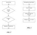
- FIG. 2 shows a high-level flowchart of operations control, according to the known art.
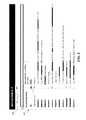
- FIG. 3 shows the steps taken to respond to an incident, according to the known art.
- a method for enhancing situational awareness in operations management includes using a processor device for performing steps or acts of: generating a user interface incorporating multiple display interfaces; receiving event data for a plurality of events monitored by an operator viewing the multiple display interfaces; receiving context data for the plurality of events, wherein the context data is received from multiple sources; matching the plurality of the events with the context data; determining the events which the operator must handle as priority events; displaying the priority events; and reducing saliency of any events and tasks that are not associated with the priority events.
- a system for enhancing situational awareness in operations management includes a memory with computer-executable instructions and a processor device operably configured to the memory for executing the instructions.
- a computer-readable storage medium has instructions stored therein for enhancing situational awareness in operations management.
- the instructions are executed by a computer and includes steps or acts of: generating a user interface incorporating multiple display interfaces; receiving event data for a plurality of events monitored by an operator viewing the multiple display interfaces; receiving context data for the plurality of events, wherein the context data is received from multiple sources; matching the plurality of the events with the context data; determining the events which the operator must handle as priority events; displaying the priority events; and reducing saliency of any events and tasks that are not associated with the priority events.
- FIG. 1 is a simplified illustration of an operator scenario, according to the known art
- FIG. 2 shows a high-level flowchart of operations control, according to the known art
- FIG. 3 shows a high-level flowchart of incident response, according to the known art
- FIG. 4 shows a flowchart of the method according to an embodiment of the present invention
- FIG. 5 shows a simplified illustration of a dual-screen display cockpit system, according to an embodiment of the present invention
- FIG. 6 is a simplified illustration of an operator scenario, according to an embodiment of the present invention.
- FIG. 7 is a high level block diagram showing an information processing system configured to operate according to an embodiment of the present invention.
- FIG. 8 is a screenshot of an exemplary situational display with an incoming alert stream, according to an embodiment of the present invention.
- FIG. 9 is a screenshot of an exemplary context display, according to an embodiment of the present invention.
- FIG. 10 shows a screenshot of an exemplary sidekick-buddy checklist, according to an embodiment of the present invention.
- FIG. 11 shows a screenshot with an event selected, according to an embodiment of the present invention.
- FIG. 12 shows a screenshot of the context view of the selected event, according to an embodiment of the present invention.
- SA situation awareness
- a situation describes the condition of the complete environment and can entail multiple incidents. For example, we could have a situation where multiple Internet services are experiencing issues caused by independent (or related) incidents.
- step 410 we receive the event data 110 .
- An exemplary event is a server running low on memory space.
- Once we receive the events 110 we perform some data mining to gather context data that is relevant to the events in step 420 .
- This data can range from a description of what to do to prevent running out of memory, to a projection of what possible effects will present when the event is serviced.
- sources 425 both internal and external sources
- step 440 we prioritize the events because, according to our saliency prerequisite, we emphasize the higher-priority events and de-emphasize the lower-priority events.
- step 450 we arrange and configure the screens/windows 455 in step 450 so that the higher-priority events are given more “real-estate” on a screen/window and so that event context (gathered in step 420 ) is presented in association with the event in the same or a different screen/window. In one embodiment this can mean presenting the list of prioritized events on one screen, and their associated event context on another screen. The operator selects the event by clicking on the event, or using a mouse-over or roll-over to bring up the context on an adjacent screen or an adjacent window within the same screen.
- FIG. 5 shows an exemplary dual-screen display cockpit system 500 enabling situational awareness for IT operators, according to an embodiment of the present invention.
- Browser Window 1 510 with information about a situation (alerts, messages)
- Browser Window 2 520 with the situational context for the events.
- the browser windows here can represent windows, screens, terminals, dialog boxes, and the like.
- the latter browser window 520 contains the information automatically assembled, aggregated and rendered by the Mashup and Knowledge Engine 550 .
- the diagram also shows events that are being tracked within and between browser windows, and between browser windows 510 , 520 and the engine 550 .
- the SA system 500 can support more than two browser windows (terminals, screens, monitors) within the spirit and scope of the invention.
- the Mashup Engine 550 in operative communication with a database 560 or data store housing the page composition data, templates, applications, and so forth required to configure the data for display in the browser windows.
- the database 560 provides the page composition data.
- the Mashup Engine 550 receives the event data from existing external data sources/tools 580 for operations management.
- the Mashup Engine 550 configures the interface 465 using the events as components that interact with each other and the server following user interaction with the Dashboard 465 .
- Internet Relay Chat is a protocol for real-time Internet text messaging (chat).
- Saliency refers to the state or quality of an item that makes it stand out relative to its neighboring items. In simpler terms, saliency is what catches the eye.
- FIGS. 8 through 12 are screenshots providing examples of the above features.
- FIG. 8 shows a situational display with an incoming alert stream 415 .
- the user is able to switch between “alert view” 830 and “incident view” 840 tabs.
- the list of alerts and incidents auto-refreshes. Clicking a row causes the context view (shown in FIG. 9 ) to update. In this example, the operator has clicked on the first row.
- FIG. 9 shows a context display 900 with the relevant situational context in plain view.
- the page widgets 930 , 940 , 950 , and 960 receive click events from the alert view 830 and perform data lookup/command execution automatically.
- a widget is an app that can be easily installed and executed from within a web page.
- the operator 180 can select from a variety of additional views via the tab control 920 .
- the two widgets 930 and 940 indicate the results of automatically executed commands against the selected node; whereas widgets 950 and 960 are data display widgets that display data resulting from queries of various data stores for information about the node. Note that this screenshot has been cropped to focus on the relevant sections
- FIG. 10 shows a context display with the ‘Runbooks’ tab selected, showing Sidekick buddy checklists 1010 .
- the checklist 1010 is a page listing the detailed steps for handling various reported error conditions.
- FIGS. 11 and 12 are two screenshots that illustrate the automatic field value propagation.
- FIG. 11 shows the Event/Incident view, which is automatically updated as new events occur in the system.
- the name of the alerting node is propagated (shown by arrows) to the context view shown in FIG. 12 (this is a partial view due to size) and causes the components in that view to auto-populate with the relevant information.
- FIG. 6 shows a data flow diagram representing IT operations management using situational awareness according to an embodiment of the present invention.
- the event stream 110 , and the procedures 130 originally performed by the IT operator 180 , and the informational tools 140 remain the same as those shown in FIG. 1 .
- the primary difference here is that much of the work that was manually done by the operator 180 in FIG. 1 is now taken care of by the SA cockpit system 620 .
- the system 620 incorporates an integrated user interface 630 displaying a situation, and an integrated user interface 640 displaying the context related to the situation (event).
- This dual user interface setup provides benefits of: a) automated organization of operator display to allocate screen real-estate to wider and narrower contexts, reinforcing mental separation of display data scopes; b) reduced context switching overhead when moving from one incident to another; c) easier handover of incident state elapsed time to another operator (whether for workload or for shift change); d) reduction of visual overload of incident eclipsing situational awareness, leading to lack of attention to new higher priority incidents, or correlation of this incident to others; e) increased potential for overview of team activities, training by screen shadowing and other additional values.
- the dual-screen display including interfaces 630 and 640 provides automated linkages between multiple screen elements based on context, even when they are from widely different tools. With the dual-screen cockpit we facilitate the arrangement of tasks into those that support situational awareness onto one screen, and those that are about this particular incident on another screen. We also provide placement of these screens to align with brain-handedness of the operator 180 .
- a mashup and knowledge engine 650 provides automated organization by performing user interface composition, user interface serving, messaging, and data feed processing.
- the mashup engine 650 receives data feeds 670 from the informational tools 140 used by the system 620 .
- the mashup engine 650 also receives action messages (via clicks) from the situational user interface 630 .
- the mashup engine 650 employs a page composition data and data feed repository 660 to provide support for templating display so that it can be consistent among operators. This enables linking of a situation to the incident by selection in the situational display leading to re-population of the entire incident display.
- the mashup engine 650 further provides support for storing and restoring the state of the visual display for each incident.
- the mashup engine 650 provides user interface refresh messages 655 to the user interface providing context 640 .
- This in turn produces the situational awareness 690 enabling the operator 180 to make more informed decisions and provides: a) faster resolution of incidents; b) higher number of simultaneous incidents handled by one operator 180 ; c) fewer higher priority incidents missed; d) easier training for operators 180 ; and e) easier handoff of incidents among team members.
- the present invention may be embodied as a system, method or computer program product. Accordingly, the present invention may take the form of an entirely hardware embodiment, an entirely software embodiment (including firmware, resident software, micro-code, etc.) or an embodiment combining software and hardware aspects that may all generally be referred to herein as a “circuit,” “module” or “system.” Furthermore, the present invention may take the form of a computer program product embodied in any tangible medium of expression having computer-usable program code embodied in the medium.
- computer system 700 may represent any type of computer, information processing system or other programmable electronic device, including a client computer, a server computer, a portable computer, an embedded controller, a personal digital assistant, and so on.
- the computer system 700 may be a stand-alone device or networked into a larger system.
- Computer system 700 illustrated for exemplary purposes as a networked computing device, is in communication with other networked computing devices (not shown) via network 710 .
- network 710 may be embodied using conventional networking technologies and may include one or more of the following: local area networks, wide area networks, intranets, public Internet and the like.
- aspects of the invention may be distributed amongst one or more networked computing devices which interact with computer system 700 via one or more data networks such as, for example, network 710 .
- network 710 data networks
- aspects of the invention have been embodied in a single computing device—computer system 700 .
- Computer system 700 includes processing device 702 which communicates with an input/output subsystem 706 , memory 704 , storage 710 and network 710 .
- the processor device 702 is operably coupled with a communication infrastructure 722 (e.g., a communications bus, cross-over bar, or network).
- the processor device 702 may be a general or special purpose microprocessor operating under control of computer program instructions executed from memory 104 on program data 734 .
- the program data 734 includes the objects and their metadata.
- the processor 702 may include a number of special purpose sub-processors such as the mashup engine 650 , each sub-processor for executing particular portions of the computer program instructions. Each sub-processor may be a separate circuit able to operate substantially in parallel with the other sub-processors.
- the memory 704 may be partitioned or otherwise mapped to reflect the boundaries of the various memory subcomponents.
- Memory 704 may include both volatile and persistent memory for the storage of: operational instructions 732 for execution by CPU 702 , data registers, application storage and the like.
- Memory 704 preferably includes a combination of random access memory (RAM), read only memory (ROM) and persistent memory such as that provided by a hard disk drive 718 .
- RAM random access memory
- ROM read only memory
- persistent memory such as that provided by a hard disk drive 718 .
- the computer instructions/applications that are stored in memory 704 are executed by processor 702 .
- the computer instructions/applications 732 and program data 734 can also be stored in hard disk drive 718 for execution by processor device 702 .
- the I/O subsystem 706 may comprise various end user interfaces such as the dual cockpit displays.
- the I/O subsystem 706 may further comprise a connection to a network 790 such as a local-area network (LAN) or wide-area network (WAN) such as the Internet.
- LAN local-area network
- WAN wide-area network
- the computer system 700 may also include a removable storage drive 710 , representing a floppy disk drive, a magnetic tape drive, an optical disk drive, etc.
- the removable storage drive 710 reads from and/or writes to a removable storage unit 720 in a manner well known to those having ordinary skill in the art.
- Removable storage unit 720 represents a floppy disk, a compact disc, magnetic tape, optical disk, CD-ROM, DVD-ROM, etc. which is read by and written to by removable storage drive 710 .
- the removable storage unit 720 includes a non-transitory computer readable medium having stored therein computer software and/or data.
- the computer system 700 may also include a communications interface 712 .
- Communications interface 712 allows software and data to be transferred between the computer system and external devices.
- Examples of communications interface 712 may include a modem, a network interface (such as an Ethernet card), a communications port, a PCMCIA slot and card, etc.
- Software and data transferred via communications interface 712 are in the form of signals which may be, for example, electronic, electromagnetic, optical, or other signals capable of being received by communications interface 712 .
- computer program medium “computer usable medium,” and “computer readable medium” are used to generally refer to both transitory and non-transitory media such as main memory 704 , removable storage drive 720 , a hard disk installed in hard disk drive 718 , and signals. These computer program products are means for providing software to the computer system 700 .
- the computer readable medium 720 allows the computer system 700 to read data, instructions, messages or message packets, and other computer readable information from the computer readable medium 720 .
Abstract
Description
Claims (20)
Priority Applications (1)
| Application Number | Priority Date | Filing Date | Title |
|---|---|---|---|
| US13/429,043 US9542292B2 (en) | 2012-03-23 | 2012-03-23 | Designing operations interface to enhance situational awareness |
Applications Claiming Priority (1)
| Application Number | Priority Date | Filing Date | Title |
|---|---|---|---|
| US13/429,043 US9542292B2 (en) | 2012-03-23 | 2012-03-23 | Designing operations interface to enhance situational awareness |
Publications (2)
| Publication Number | Publication Date |
|---|---|
| US20130254711A1 US20130254711A1 (en) | 2013-09-26 |
| US9542292B2 true US9542292B2 (en) | 2017-01-10 |
Family
ID=49213535
Family Applications (1)
| Application Number | Title | Priority Date | Filing Date |
|---|---|---|---|
| US13/429,043 Active 2032-03-30 US9542292B2 (en) | 2012-03-23 | 2012-03-23 | Designing operations interface to enhance situational awareness |
Country Status (1)
| Country | Link |
|---|---|
| US (1) | US9542292B2 (en) |
Cited By (2)
| Publication number | Priority date | Publication date | Assignee | Title |
|---|---|---|---|---|
| US10120552B2 (en) * | 2015-09-25 | 2018-11-06 | International Business Machines Corporation | Annotating collaborative content to facilitate mining key content as a runbook |
| US10681054B2 (en) | 2015-09-25 | 2020-06-09 | International Business Machines Corporation | Enabling a multi-dimensional collaborative effort system |
Families Citing this family (6)
| Publication number | Priority date | Publication date | Assignee | Title |
|---|---|---|---|---|
| US9223494B1 (en) * | 2012-07-27 | 2015-12-29 | Rockwell Collins, Inc. | User interfaces for wearable computers |
| US9069604B2 (en) * | 2013-03-04 | 2015-06-30 | Yagi Corp. | Activity interruption management |
| US9525604B2 (en) * | 2014-03-18 | 2016-12-20 | International Business Machines Corporation | Automated synchronization of distributed dashboards |
| US9959545B2 (en) | 2014-11-12 | 2018-05-01 | Sap Se | Monitoring of events and key figures |
| EP3065093A1 (en) * | 2015-03-06 | 2016-09-07 | Amadeus S.A.S. | Generating a setting recommendation for a revenue management system |
| US20230315601A1 (en) * | 2022-04-04 | 2023-10-05 | Palantir Technologies Inc. | Approaches of incident monitoring and resolution |
Citations (17)
| Publication number | Priority date | Publication date | Assignee | Title |
|---|---|---|---|---|
| US20040098462A1 (en) * | 2000-03-16 | 2004-05-20 | Horvitz Eric J. | Positioning and rendering notification heralds based on user's focus of attention and activity |
| US20050022189A1 (en) * | 2003-04-15 | 2005-01-27 | Alcatel | Centralized internet protocol/multi-protocol label switching connectivity verification in a communications network management context |
| US20050228763A1 (en) * | 2004-04-03 | 2005-10-13 | Altusys Corp | Method and Apparatus for Situation-Based Management |
| US20060085367A1 (en) * | 2000-02-23 | 2006-04-20 | Genovese James A | System and method for hazardous incident decision support and training |
| US7089278B1 (en) * | 1999-09-07 | 2006-08-08 | Fuji Xerox Co., Ltd. | Anchored conversations: adhesive, in-context, virtual discussion forums |
| US20070192128A1 (en) * | 2006-02-16 | 2007-08-16 | Shoplogix Inc. | System and method for managing manufacturing information |
| US20070233854A1 (en) * | 2006-03-31 | 2007-10-04 | Microsoft Corporation | Management status summaries |
| US20080016569A1 (en) * | 2000-10-10 | 2008-01-17 | Internet Security Systems, Inc. | Method and System for Creating a Record for One or More Computer Security Incidents |
| US20080155008A1 (en) * | 2006-05-09 | 2008-06-26 | Lockheed Martin Corporation | Track sort and select system |
| US7467192B1 (en) * | 2000-06-07 | 2008-12-16 | Cisco Technology, Inc. | Online standardized contract configuration for service level agreement monitoring |
| US20110035326A1 (en) * | 2008-04-25 | 2011-02-10 | Sholl Jeffrey J | System And Method Of Providing Product Quality And Safety |
| US20110134797A1 (en) * | 2009-11-05 | 2011-06-09 | Kevin Banks | Wireless communication systems and methods |
| US20120209925A1 (en) * | 2011-02-11 | 2012-08-16 | Acer Incorporated | Intelligent data management methods and systems, and computer program products thereof |
| US20130150686A1 (en) * | 2011-12-07 | 2013-06-13 | PnP INNOVATIONS, INC | Human Care Sentry System |
| US20130151421A1 (en) * | 2011-12-08 | 2013-06-13 | Oracle International Corporation | Real-time project progress entry: applying project team member-entered progress immediately to the project plan |
| US20130238356A1 (en) * | 2010-11-05 | 2013-09-12 | Georgetown University | System and method for detecting, collecting, analyzing, and communicating emerging event- related information |
| US20140245439A1 (en) * | 2011-02-17 | 2014-08-28 | Christopher Wayne Day | Systems and Methods for Detection and Suppression of Abnormal Conditions Within a Networked Environment |
-
2012
- 2012-03-23 US US13/429,043 patent/US9542292B2/en active Active
Patent Citations (17)
| Publication number | Priority date | Publication date | Assignee | Title |
|---|---|---|---|---|
| US7089278B1 (en) * | 1999-09-07 | 2006-08-08 | Fuji Xerox Co., Ltd. | Anchored conversations: adhesive, in-context, virtual discussion forums |
| US20060085367A1 (en) * | 2000-02-23 | 2006-04-20 | Genovese James A | System and method for hazardous incident decision support and training |
| US20040098462A1 (en) * | 2000-03-16 | 2004-05-20 | Horvitz Eric J. | Positioning and rendering notification heralds based on user's focus of attention and activity |
| US7467192B1 (en) * | 2000-06-07 | 2008-12-16 | Cisco Technology, Inc. | Online standardized contract configuration for service level agreement monitoring |
| US20080016569A1 (en) * | 2000-10-10 | 2008-01-17 | Internet Security Systems, Inc. | Method and System for Creating a Record for One or More Computer Security Incidents |
| US20050022189A1 (en) * | 2003-04-15 | 2005-01-27 | Alcatel | Centralized internet protocol/multi-protocol label switching connectivity verification in a communications network management context |
| US20050228763A1 (en) * | 2004-04-03 | 2005-10-13 | Altusys Corp | Method and Apparatus for Situation-Based Management |
| US20070192128A1 (en) * | 2006-02-16 | 2007-08-16 | Shoplogix Inc. | System and method for managing manufacturing information |
| US20070233854A1 (en) * | 2006-03-31 | 2007-10-04 | Microsoft Corporation | Management status summaries |
| US20080155008A1 (en) * | 2006-05-09 | 2008-06-26 | Lockheed Martin Corporation | Track sort and select system |
| US20110035326A1 (en) * | 2008-04-25 | 2011-02-10 | Sholl Jeffrey J | System And Method Of Providing Product Quality And Safety |
| US20110134797A1 (en) * | 2009-11-05 | 2011-06-09 | Kevin Banks | Wireless communication systems and methods |
| US20130238356A1 (en) * | 2010-11-05 | 2013-09-12 | Georgetown University | System and method for detecting, collecting, analyzing, and communicating emerging event- related information |
| US20120209925A1 (en) * | 2011-02-11 | 2012-08-16 | Acer Incorporated | Intelligent data management methods and systems, and computer program products thereof |
| US20140245439A1 (en) * | 2011-02-17 | 2014-08-28 | Christopher Wayne Day | Systems and Methods for Detection and Suppression of Abnormal Conditions Within a Networked Environment |
| US20130150686A1 (en) * | 2011-12-07 | 2013-06-13 | PnP INNOVATIONS, INC | Human Care Sentry System |
| US20130151421A1 (en) * | 2011-12-08 | 2013-06-13 | Oracle International Corporation | Real-time project progress entry: applying project team member-entered progress immediately to the project plan |
Cited By (3)
| Publication number | Priority date | Publication date | Assignee | Title |
|---|---|---|---|---|
| US10120552B2 (en) * | 2015-09-25 | 2018-11-06 | International Business Machines Corporation | Annotating collaborative content to facilitate mining key content as a runbook |
| US10671263B2 (en) | 2015-09-25 | 2020-06-02 | International Business Machines Corporation | Annotating collaborative content to facilitate mining key content as a runbook |
| US10681054B2 (en) | 2015-09-25 | 2020-06-09 | International Business Machines Corporation | Enabling a multi-dimensional collaborative effort system |
Also Published As
| Publication number | Publication date |
|---|---|
| US20130254711A1 (en) | 2013-09-26 |
Similar Documents
| Publication | Publication Date | Title |
|---|---|---|
| US9542292B2 (en) | Designing operations interface to enhance situational awareness | |
| US9716613B2 (en) | Automated alert management | |
| US9135093B2 (en) | Event-driven approach for collecting monitoring data of messaging systems | |
| US8966392B2 (en) | Event management apparatus, systems, and methods | |
| EP2561444B1 (en) | Automated recovery and escalation in complex distributed applications | |
| US11132109B2 (en) | Timeline visualization and investigation systems and methods for time lasting events | |
| US8775529B2 (en) | Bridging communications between communication services using different protocols | |
| US20110032260A1 (en) | Enhancing visualization of relationships and temporal proximity between events | |
| US7804766B2 (en) | Devices, systems, and/or methods regarding virtual routing forwarding | |
| CN106301823B (en) | Fault warning method and device for key component and big data management system | |
| EP3187991A1 (en) | Method and system for integrated application notifications | |
| US20030135382A1 (en) | Self-monitoring service system for providing historical and current operating status | |
| US10515323B2 (en) | Operations command console | |
| CN109450693B (en) | Hybrid cloud monitoring system and monitoring method using same | |
| US9092329B2 (en) | Process integration alerting for business process management | |
| US20120290705A1 (en) | Component Independent Process Integration Message Monitoring | |
| US20150269856A1 (en) | Virtual classroom management system and interface | |
| US11743155B2 (en) | Systems and methods of monitoring and controlling remote assets | |
| US9756552B1 (en) | Reducing distractions caused by user devices in group settings | |
| US20150348513A1 (en) | Gaze based notification placement | |
| US20160321099A1 (en) | Executable process-management engines | |
| CN104579840A (en) | ZABBIX-based network monitoring system | |
| US20100179992A1 (en) | Generatiing Context Aware Data And Conversation's Mood Level To Determine The Best Method Of Communication | |
| US20120030572A1 (en) | Network visualization system | |
| CN112491858B (en) | Method, device, equipment and storage medium for detecting abnormal information |
Legal Events
| Date | Code | Title | Description |
|---|---|---|---|
| AS | Assignment |
Owner name: YAHOO! INC., CALIFORNIA Free format text: ASSIGNMENT OF ASSIGNORS INTEREST;ASSIGNORS:SIEVERT, STEFAN;RICHARDS, ADAM JOHN;REEL/FRAME:027920/0845 Effective date: 20120320 |
|
| STCF | Information on status: patent grant |
Free format text: PATENTED CASE |
|
| AS | Assignment |
Owner name: YAHOO HOLDINGS, INC., CALIFORNIA Free format text: ASSIGNMENT OF ASSIGNORS INTEREST;ASSIGNOR:YAHOO! INC.;REEL/FRAME:042963/0211 Effective date: 20170613 |
|
| AS | Assignment |
Owner name: OATH INC., NEW YORK Free format text: ASSIGNMENT OF ASSIGNORS INTEREST;ASSIGNOR:YAHOO HOLDINGS, INC.;REEL/FRAME:045240/0310 Effective date: 20171231 |
|
| MAFP | Maintenance fee payment |
Free format text: PAYMENT OF MAINTENANCE FEE, 4TH YEAR, LARGE ENTITY (ORIGINAL EVENT CODE: M1551); ENTITY STATUS OF PATENT OWNER: LARGE ENTITY Year of fee payment: 4 |
|
| AS | Assignment |
Owner name: VERIZON MEDIA INC., NEW YORK Free format text: ASSIGNMENT OF ASSIGNORS INTEREST;ASSIGNOR:OATH INC.;REEL/FRAME:054258/0635 Effective date: 20201005 |
|
| AS | Assignment |
Owner name: YAHOO ASSETS LLC, VIRGINIA Free format text: ASSIGNMENT OF ASSIGNORS INTEREST;ASSIGNOR:YAHOO AD TECH LLC (FORMERLY VERIZON MEDIA INC.);REEL/FRAME:058982/0282 Effective date: 20211117 |
|
| AS | Assignment |
Owner name: ROYAL BANK OF CANADA, AS COLLATERAL AGENT, CANADA Free format text: PATENT SECURITY AGREEMENT (FIRST LIEN);ASSIGNOR:YAHOO ASSETS LLC;REEL/FRAME:061571/0773 Effective date: 20220928 |