US9516451B2 - Opportunistic system scanning - Google Patents
Opportunistic system scanning Download PDFInfo
- Publication number
- US9516451B2 US9516451B2 US13/443,729 US201213443729A US9516451B2 US 9516451 B2 US9516451 B2 US 9516451B2 US 201213443729 A US201213443729 A US 201213443729A US 9516451 B2 US9516451 B2 US 9516451B2
- Authority
- US
- United States
- Prior art keywords
- scan
- computing device
- network
- detected
- engine
- Prior art date
- Legal status (The legal status is an assumption and is not a legal conclusion. Google has not performed a legal analysis and makes no representation as to the accuracy of the status listed.)
- Active
Links
Images


Classifications
-
- H04W4/008—
-
- H04W4/006—
-
- H—ELECTRICITY
- H04—ELECTRIC COMMUNICATION TECHNIQUE
- H04W—WIRELESS COMMUNICATION NETWORKS
- H04W4/00—Services specially adapted for wireless communication networks; Facilities therefor
- H04W4/30—Services specially adapted for particular environments, situations or purposes
- H04W4/38—Services specially adapted for particular environments, situations or purposes for collecting sensor information
-
- H—ELECTRICITY
- H04—ELECTRIC COMMUNICATION TECHNIQUE
- H04W—WIRELESS COMMUNICATION NETWORKS
- H04W4/00—Services specially adapted for wireless communication networks; Facilities therefor
- H04W4/80—Services using short range communication, e.g. near-field communication [NFC], radio-frequency identification [RFID] or low energy communication
Definitions
- This disclosure relates in general to the field of computing security and, more particularly, to security scanning.
- Various tools have been used by network administrators, government, security consultants, and hackers to test the vulnerabilities of target networks, such as, for example, whether any computers on a network can be accessed and controlled remotely without authorization.
- Some network security tools can test network paths for possible intrusion. From a testing point, simple commands such as traceroute and ping can be used to manually map a network topography, and determine roughly what network addresses are “alive” and which computers are “awake” on the network (i.e., determine which computers are on and are responding to network packets).
- a tool such as a port scanner can be used to test an individual target computer on the target network to determine what network ports are open. If open ports are found, these ports may provide access for possible intrusion, and potentially represent a vulnerability that can be exploited by a malicious hacker.
- Network security tools can perform various tests and scans of computers in a network, performing the scans on all or a portion of the computing environment, for instance, according to a particular scanning session.
- FIG. 1 is a simplified schematic diagram of an example computing system including an example asset management system in accordance with at least one embodiment
- FIG. 2 is a simplified block diagram of an example computing system including an example asset management system, example asset detection tools, and example scan engines in accordance with at least one embodiment;
- FIG. 3 is a simplified block diagram illustrating deployment of asset detection engines and scan engines in two or more networks of an example computing environment in accordance with at least one embodiment
- FIGS. 4A-4D are simplified block diagrams illustrating example operations of an example asset management system and example asset detection tools in accordance with at least one embodiment
- FIGS. 5A-5E are simplified block diagrams illustrating example operations of an example asset management system and example scan engines in accordance with at least one embodiment
- FIG. 6 is a simplified flowchart illustrating example techniques for scanning portions of a computing environment in accordance with at least one embodiment.
- one aspect of the subject matter described in this specification can be embodied in methods that include the actions of identifying, using at least one processing device, a detection of a particular computing device on a network of a computing environment. At least one scan to be performed on the detected particular computing device can be identified and a particular scan engine, in a plurality of scan engines, can be identified that is adapted to perform the at least one scan. The at least one scan can be caused to be performed on the detected particular computing device while the detected particular computing device is on the network using the particular scan engine.
- the asset manager can be adapted, when executed by the at least one processor device, to receive a request to identify a detection of a particular computing device on a network of a computing environment, identify at least one scan to be performed on the detected particular computing device, identify a particular scan engine in a plurality of scan engines adapted to perform the at least one scan, and cause the at least one scan to be performed on the detected computing device while the detected computing device is on the network using the particular scan engine.
- the systems can include an asset detection engine adapted to detect activity of computing devices within the network and obtain identifications of the detected computing devices, as well as, in some instance, the plurality of scan engines.
- the particular scan engine can be remote from the detected particular computing device.
- the particular scan engine can be adapted to perform network-based scans of remote computing devices. Scan results of the performed at least one scan can be received.
- the particular computing device can be a mobile computing device.
- the particular computing device can be detected by an asset detection tool on the network and detection of the particular computing device can be identified from a message from the asset detection tool.
- the asset detection tool can be a passive detection tool.
- the particular computing device can be detected from data collected by a service in the network in connection with an event identified by the service.
- the particular computing device can also be detected from address information corresponding to the particular computing device included in traffic communicated in the network.
- the particular computing device can be detected from address information added to a data store of a service within the network.
- the particular scan engine can be identified as associated with the asset detection tool detecting the particular computing device and the asset detection tool can be one of a plurality of asset detection tools in the computing environment. Identifying the particular scan engine as associated with the asset detection tool can include querying a mapping of scan engines to asset detection tools.
- the asset detection tool can be an active detection tool adapted to probe computing devices and detect whether computing devices are present on the network based on the probing.
- Causing the at least one scan to be performed can include sending a scan request to the identified particular scan engine.
- the scan request can include a scan script that, when executed by the particular scan engine, causes the particular scan engine to perform the at least one scan.
- a plurality of scans can be identified to be performed on the detected particular computing device. At least two different scan engines can be identified to perform respective scans in the plurality of scans and two or more of the plurality of scans can be caused to be performed.
- the identified particular computing device is designated as a device to be scanned using the at least one scan in response to detection of the particular computing device within networks of the computing environment.
- detection of a second computing device on the network of the computing environment can be identified and at least one second scan to be performed on the detected second computing device can be identified.
- a scan engine in the plurality of scan engines can be identified that is adapted to perform the at least one second scan and the at least one second scan can be caused to be performed on the detected second computing device while the detected second computing device is on the network.
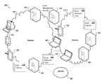
- FIG. 1 is a simplified block diagram illustrating an example implementation of a computing environment 100 including an asset management system 105 managing assets of the computing environment 100 including one or more networks (e.g., 110 , 115 ) and computing devices (e.g., 120 , 125 , 130 , 140 , 145 , 150 , 155 , 160 , 165 ) within the networks 110 , 115 .
- Such computing devices can include user computing devices (e.g., 120 , 125 , 130 , 140 , 150 , 155 ), server devices serving various services, data, applications, and other resources within the computing environment (e.g., 135 , 145 , 160 , 165 ), and other host devices.
- the computing environment 100 can additionally include scan engines 170 , 175 deployed in the networks 110 , 115 adapted to probe, test, attempt to access, and otherwise scan the devices (e.g., 120 , 125 , 130 , 140 , 150 , 155 ) in the computing environment according to one or more of a variety of scans.
- Some scan engines 170 , 175 can include functionality for performing multiple different types of scans while other scan engines can be specialized scan engines adapted to perform a particular type of scan, scan particular types of devices on the computing environment, etc.
- scan engines 170 , 175 can attempt to obtain information regarding attributes of the various elements of the computing environment 100 , its respective host devices (e.g., 110 , 115 , 120 , 125 , 130 , 135 , 140 ), applications and services hosted by the devices, and networks (e.g., 145 ) within the computing environment 100 , as well as individual network elements, such as routers, switches, firewalls, etc.
- attributes can include the type of host, the operating system of the host, hardware profile of the host, applications of the host (and attributes of these applications), ports used by the host, vulnerabilities possessed by the host, the location of the host, the user of the host, etc.
- scan engines 170 , 175 can scan host devices to additionally obtain information describing attributes of various users/persons using the computing environment 100 (e.g., through the scanned host), as well as behavioral tendencies of the users/persons. Data generated, discovered, and/or collected by scan engines 170 , 175 through various scans of the computing environment can be sent to an at least partially centralized asset management system 105 for aggregating, synthesizing, and otherwise processing the result data as it is generated in connection with security-related assessments of the computing environment 100 .
- scan engines can be run according to particular schedules, on a periodic basis, according to an administrator request, etc.
- a particular scan of a scan engine can be attempted to be run against a number of host devices within the computing environment at substantially the same time (e.g., at a time when scanning is believed to be the least disruptive, etc.), for instance, during a defined scan window.
- scans can be run under the assumption that most targeted hosts are present on a network of the computing environment 100 at the time of the scan. In practice, however, this is not always true. For instance, particularly as computing devices become more mobile, computing devices may move on and off networks of the computing environment.
- a scan of at least a portion of the computing environment may miss certain targeted host devices that are not on the network at the time of the scan.
- such realities are sometimes addressed by staggering or randomizing the scheduling of scans, based on the assumption that eventually host devices missed in a previous scan will be on the network during a future scan.
- This is a less than optimal solution, particular in instances where an urgent scan is to be performed or where particular host devices (e.g., by virtue of their user's use behavior) are off the networks 110 , 115 more often than they are on.
- increasing the frequency or randomizing the scheduling of scans can additionally result in redundant scanning of some host devices in the computing environment in attempts to catch certain hosts missed in previous scans, among other examples and difficulties.
- an example asset management system 105 can at least partially centralize control of scans performed by scan engines 170 , 175 as well as the processing of scan result data obtained from the scans so as to perform on-demand scanning of devices in response to detection of the devices.
- asset detection tools e.g., 180 , 185
- asset management system 105 can additionally be provided and communicate with asset management system 105 in connection with the management of scans of scan engines 170 , 175 within the computing environment 100 .
- Such asset detection tools can be provided with functionality to actively and passively collect data and communications within the computing environment to detect the presence of various computing devices within networks 110 , 115 of the computing environment. Such detections can be communicated to the asset management system 105 to provide the asset management system 105 with the opportunity to trigger an attempted on-demand scan of the detected computing device, among other examples.
- system administrators can invest much time and resources into securing a computing environment (e.g., 100 ) from various threats that exploit particular vulnerabilities of systems in the computing environment. Further, at least portions of the computing environment 100 can be beholden to or governed by particular policies, and monitoring or auditing compliance with these policies can be burdensome endeavor for administrators and the tools they employ in the management of their systems.
- endpoint or user devices, network elements, host devices, and other computing devices included in a computing environment 100 can communicate with and/or facilitate communication between other devices, including devices outside the computing environment (e.g., over one or more public networks (e.g., 190 )). Vulnerabilities and threats can materialize from devices' participation in computing transactions and communications both inside and outside the computing environment 100 .
- the presence of various vulnerabilities within a system can open the door to the computing environment 100 being harmed by threats exploiting the vulnerabilities, including computer viruses, compromised data, unauthorized system, data, or network access, data theft, worms, malware, hacks, and other threats. Such vulnerabilities and threats can pose risks to one or more devices, sub-networks, or the computing environment itself. Additionally, various policies under which the computing environment is governed can additionally mandate particular compliance with one or more policies by the computing environment. Efficiently and accurately scanning devices and networks within the computing environment 100 can assist in ensuring various security standards and policies are upheld, and that the security and health of the overall computing environment 100 and its constituent elements are maintained.
- servers can include electronic computing devices operable to receive, transmit, process, store, or manage data and information associated with the computing environment 100 .
- computer can include processors operable to receive, transmit, process, store, or manage data and information associated with the computing environment 100 .
- processor processor device
- processing device is intended to encompass any suitable processing device.
- elements shown as single devices within the computing environment 100 may be implemented using a plurality of devices, such as server pools including multiple server computers.
- any, all, or some of the computing devices may be adapted to execute any operating system, including Linux, UNIX, Microsoft Windows, Apple OS, Apple iOS, Google Android, Windows Server, etc., as well as virtual machines adapted to virtualize execution of a particular operating system, including customized and proprietary operating systems.
- any operating system including Linux, UNIX, Microsoft Windows, Apple OS, Apple iOS, Google Android, Windows Server, etc.
- virtual machines adapted to virtualize execution of a particular operating system, including customized and proprietary operating systems.
- servers, clients, network elements, systems, and computing devices can each include one or more processors, computer-readable memory, and one or more interfaces, among other features and hardware.
- Servers can include any suitable software component or module, or computing device(s) capable of hosting and/or serving software applications and services (e.g., the asset management system 105 , scan engines 170 , 175 , asset detection tools 180 , 185 , security enforcement tools, and other services, applications, and other programs including distributed, enterprise, or cloud-based software applications, data, and services.
- servers can be configured to host, serve, or otherwise manage data structures, models, data sets, software services and applications interfacing, coordinating with, or dependent on or used by other services and devices.
- a server, system, subsystem, or computing device can be implemented as some combination of devices that can be hosted on a common computing system, server, server pool, or cloud computing environment and share computing resources, including shared memory, processors, and interfaces.
- User, endpoint, or client computing devices can include traditional and mobile computing devices, including personal computers, laptop computers, tablet computers, smartphones, personal digital assistants, feature phones, handheld video game consoles, desktop computers, internet-enabled televisions, and other devices designed to interface with human users and capable of communicating with other devices over one or more networks (e.g., 110 , 115 , 190 ). Attributes of user computing devices, and computing devices generally, can vary widely from device to device, including the respective operating systems and collections of software programs loaded, installed, executed, operated, or otherwise accessible to each device.
- computing devices can run, execute, have installed, or otherwise include various sets of programs, including various combinations of operating systems, applications, plug-ins, applets, virtual machines, machine images, drivers, executable files, and other software-based programs capable of being run, executed, or otherwise used by the respective devices.
- Some computing devices can further include at least one graphical display device and user interfaces allowing a user to view and interact with graphical user interfaces of applications and other programs provided in computing environment 100 , including user interfaces and graphical representations of programs interacting with applications hosted within the computing devices as well as graphical user interfaces associated with an asset management system 105 , or one or more scan engines 170 , 175 ).
- user computing devices may be described in terms of being used by one user, this disclosure contemplates that many users may use one computer or that one user may use multiple computers.
- FIG. 1 is described as containing or being associated with a plurality of elements, not all elements illustrated within computing environment 100 of FIG. 1 may be utilized in each alternative implementation of the present disclosure. Additionally, one or more of the elements described in connection with the examples of FIG. 1 may be located external to computing environment 100 , while in other instances, certain elements may be included within or as a portion of one or more of the other described elements, as well as other elements not described in the illustrated implementation. Further, certain elements illustrated in FIG. 1 may be combined with other components, as well as used for alternative or additional purposes in addition to those purposes described herein.
- FIG. 2 is a simplified block diagram 200 illustrating an example system including an example asset management system 205 operating cooperatively with one or more scan engines (e.g., 215 ) hosted by one or more hosts (e.g., 210 ) within the computing environment.
- Asset management system 205 can further communicate with, and in some cases, manage one or more asset detection engines (e.g., 220 ) also hosted by devices in the computing environment and tasked with discovering computing devices (e.g., typed as “system-type system entities”) (e.g., 228 , 230 , 235 , 240 ) within the network 225 , together with addresses and attributes of the discovered devices.
- asset detection engines e.g., 220
- discovering computing devices e.g., typed as “system-type system entities”
- the detection of devices within the network by asset detection engines 220 can be communicated to the asset management system for use by the asset management system in dynamically identifying one or more scans to be performed on a discovered device while it remains (potentially temporarily) on the network and within reach of a scan engine adapted to perform the identified scans.
- the scanning of devices in the network 215 can permit the discovery of further attributes of the devices including vulnerabilities and policy violations present on or through the device that the asset management system 205 can attempt to counter utilizing one or more security tools, including network-based security tools 245 remote from the detected device (e.g., 230 ) as well as locally-executed (or host-based) security tools, such as tools provided by an agent (e.g., 244 ) present on the device (e.g., 230 ), among other examples.
- security tools including network-based security tools 245 remote from the detected device (e.g., 230 ) as well as locally-executed (or host-based) security tools, such as tools provided by an agent (e.g., 244 ) present on the device (e.g., 230 ), among other examples.
- An example asset management system 205 can include one or more processors devices 250 and memory elements 252 used to execute functionality included, in some implementations, in one or more components of the asset management system 205 .
- a scan controller 255 can be provided in one example implementation of an asset management system 205 .
- An example scan controller 260 can include functionality for interfacing with one or more scan engines (e.g., 220 , 225 ) and managing scan sets and individual scans performed by the scan engines. In this way, asset management system 205 can centrally manage scans as well as the information obtained through the scans of the computing environment, including scans across multiple networks within the computing environment.
- asset management system 205 can orchestrate scans involving many scans (i.e., a set of scans) by multiple different scan engines, including both network- and host-based scan engines, and can adapt scan scripts used by the scan engines based on scan results received during one or more portions of the scan set. Further, the result data obtained or generated using one or more different scan engines can be centrally reported to asset management system for aggregation, synthesis, and analysis by the asset management system.
- policies can be associated with one or more components of a computing environment, such as the entire environment, a network, one or more subnets, one or more devices, one or more applications, one or more users, etc.
- policies can include user-centric policies (e.g., applied against a particular user's use of devices and networks of the computing environment), device-centric policies (e.g., applied against particular devices within the computing environment), organization-specific policies (e.g., policies set by an organization governing uses and configurations within a particular organization's computing environment), and regulatory policies (e.g., policies set by industry, government, or other entities setting system requirements and guidelines of computing systems used within particular contexts governed by the entity (e.g., Sarbanes-Oxley system compliance policies, Payment Card Industry (PCI) policies, Health Insurance Portability and Accountability Act (HIPAA) policies, etc.)), among other examples.
- PCI Payment Card Industry
- HIPAA Health Insurance Portability and Accountability Act
- a scan controller 255 can be adapted to generate particular scans (or identify pre-developed scans, including third-party scans), including sets of scans that involve a sequence of a scans, performed, in some cases, by a plurality of different scan engines, addressing compliance with a particular policy (e.g., 275 ).
- a variety of scan scripts 272 can be generated and maintained using scan controller 260 for use in performing scans in connection with one or more policies 275 .
- Scan scripts 272 can be pushed by a scan controller 255 to one or more particular scan engines 215 , for use by the scan engines in performing corresponding scan tasks.
- a scan script 272 can include executable instructions that, when read or executed by the scan engine, identify particular scan targets, the scans to be performed, as well as, in some instances, the type of computing language to be used by the scan engine in performing the scan task. Execution of a scan script can cause a scan engine to perform one or more scan tasks.
- a scan can involve the collection of data from a particular device or application within the computing environment.
- a scan can include an attempt (authorized or unauthorized from the perspective of the target) to access particular resources of a target computing device or application.
- a scan can include monitoring the response of a particular device or application within the computing environment to particular stimuli or data sent to the computing device or application.
- a scan can include the generation of data by a scan engine to be provided as inputs to, communicated to, or otherwise sent to a target of the scan, the scan engine further monitoring the response of the scan target to the sent data.
- data, sent by the scan engine 2105 can be based on a particular scan script 272 received from the scan controller 255 and be in the computing language(s) in which the data is to be generated and sent within the scan.
- data returned from a target can be interpreted using one or more language interpreters of the scan engine 215 to generate scan result data describing the responses of the target and other results of the scan.
- a scan controller 255 can further interface with scan engines (e.g., 215 ) to obtain scan result data returned from scan tasks performed by the scan engines. Further, a scan controller 255 , in some implementations, can organize and aggregate scan result data (e.g., 274 ) in accordance with particular goals of the scan (e.g., measuring compliance with a particular security policy upon which the scan(s) is based, checking for a particular vulnerability, etc.). Further, a scan controller 255 can process scan result data to determine that desired information has been obtained from the scan or to determine that a particular type of scan was unsuccessful in obtaining particular information desired for a particular scan or set of scans, such as information for determining compliance with a particular security policy upon which the scans are based, among other examples.
- scan engines e.g., 215
- a scan controller 255 can organize and aggregate scan result data (e.g., 274 ) in accordance with particular goals of the scan (e.g., measuring compliance with a particular security policy upon which the
- a scan controller 255 can adapt a scan by cancelling a scan prematurely, replacing a scan script with another scan script, sending supplemental scan scripts to a scan engine, invoking another scan on another scan engine, among other examples to control the progress of the scan, among other examples.
- scan controllers 255 can also identify particular scan engines adapted to perform particular scans. For instance, some scan engines may be particularly adapted to perform particular scans. For example, a scan engine can be specialized in its ability to scan and communicate with particular devices, services, and applications within the network 225 . In other instances, some scan engines available on the network can be capable of performing a variety of different scans. Scan engines can include both host-based scan engines locally hosted on target devices (e.g., via an agent installed on the target device) or network-based scan engines remote from the target device, capable of externally probing a target device over the network 225 .
- a scan controller 255 may additionally determine whether a particular network-based scan engine (e.g., 215 ) is capable of communicating with and thereby scanning a particular remote scan target (e.g., computing devices 228 , 230 , 235 , 240 ). Such a determination could include determining whether the particular scan engine is on the same network as the scan target or is otherwise able to interface with the remote scan target. For instance, in some implementations, a scan controller 255 can identify from a mapping of scan targets to scan engines (i.e., identifying which scan controllers are capable of communicating with which scan targets) that a particular network-based scan engine is adapted to communicate with the scan target.
- a mapping of scan targets to scan engines i.e., identifying which scan controllers are capable of communicating with which scan targets
- the scan controller 255 can forward the scan engine (e.g., 215 ) a scan script (e.g., 272 ) for use by the scan engine in scanning the scan target (e.g., computing device 240 ) over one or more networks (e.g., 225 ).
- the scan engine e.g., 215
- a scan script e.g., 272
- a mapping of scan engines to scan targets can be maintained in connection with an asset repository 270 cataloguing system assets within the computing environment.
- System assets can include networks, applications and other programs, individual devices or sub-systems within the computing environment, particular users or persons identified as using the computing environment, etc.
- the asset repository 270 can further catalogue identified attributes of the various system assets, for instance, to assist in identifying vulnerabilities of the system entities.
- Information included in the asset repository 270 can also be accessed by scan controller 255 to inform how to perform particular scans on particular scan targets (i.e., system assets to be scanned), which scan targets to scan, which scan engines to invoke to scan particular scan targets, attributes of the scan target to consider, etc. Additionally, scanning of particular system assets can result in the discovery of additional information and attributes of the system asset.
- an asset repository manager 255 can include functionality for building, updating, and otherwise maintaining an asset repository 270 including records describing system assets discovered within the computing environment.
- a detection interface module 260 can further be provided on asset management system that can allow the asset management system 205 to interface with asset detection engines 220 deployed within the computing environment and obtain results from the asset detection engines identifying host devices discovered on the network 225 or elsewhere in the computing environment, as well as attributes detected for the detected devices, such as address data and other information.
- Asset detection engines e.g., 220
- deployed throughout a network e.g., 225
- An asset detection engine 220 can push alerts, notifications, or other messages to asset management system 205 to indicate that a particular detected computing device may be available for scanning (e.g., using scan engine 215 ).
- example asset management systems 205 can further include a policy administrator 268 that can be used to define and apply security policies to system assets identified and catalogued in asset repository 270 .
- a library of security policies 275 can be maintained and accessed using policy administrator 268 .
- security policies 275 can include standard security policies (e.g., generally applicable across computing environments), as well as environment-specific security policies.
- policy administrator 268 can include functionality allowing administrator users to define and generate new, customized security policies for their respective computing environments.
- a policy administrator 268 can associate, either from user-entered associations or automated associations (e.g., rule-based policy assignments based on attributes of a respective system asset recorded in asset repository 270 ) which policies 275 apply to which system entities. Such associations can also be considered by scan controller 255 to identify the portion of the computing environment (e.g., particular scan target devices, a particular sub-network, etc.) to be scanned in a scan or scan set corresponding to enforcement or auditing of a particular policy 275 , identify particular scans for particular identified scan targets, among other examples.
- automated associations e.g., rule-based policy assignments based on attributes of a respective system asset recorded in asset repository 270
- Such associations can also be considered by scan controller 255 to identify the portion of the computing environment (e.g., particular scan target devices, a particular sub-network, etc.) to be scanned in a scan or scan set corresponding to enforcement or auditing of a particular policy 275 , identify particular scans for particular identified scan targets, among other examples
- Security tools 245 can be deployed remote from system assets (e.g., 228 , 230 , 235 , 240 ) allowing for policy enforcement to take place remote from and behalf of the target (i.e., target of a security enforcement action by one or more of security tools 245 ), allowing security enforcement without the policy (or enforcement tool) being pushed to the target itself.
- system assets e.g., 228 , 230 , 235 , 240
- Such network-based security tools 245 can include, for example, firewalls, web gateways, mail gateways, host intrusion protection (HIP) tools, network intrusion protection (NIP) tools, anti-malware tools, data loss prevention (DLP) tools, system vulnerability managers, system policy compliance managers, asset criticality tools, intrusion detection systems (IDS), intrusion protection systems (IPS), and/or a security information management (SIM) tool, among other examples.
- HIP host intrusion protection
- NIP network intrusion protection
- DLP data loss prevention
- IDS intrusion detection systems
- IPS intrusion protection systems
- SIM security information management
- agents e.g., 244
- other tools running, loaded, or otherwise interfacing directly with a target device (e.g., 230 ) and providing asset management system 205 with an interface for enforcing policy directly at the target device, among other examples.
- Scan engines can be deployed on hosts devices (e.g., 210 ) within a network 225 .
- Scan engines can be embodied in software and/or hardware and include at least one processor and one memory device.
- Scan engines can include functionality for performing one or more scan tasks, including scan tasks making use of one or more different computing languages.
- a scan engine can scan devices according to a particular computing language to elicit a response to a particular service, application, or device making use of that computing language.
- the scan task and scan language used by a scan engine in a particular scan or set of scans can be based on scan scripts and other instructions received from an asset management system in a scan request.
- scan engines can include network-based scan engine and host-based scan engines.
- a network-based scan engine can execute a scan script that causes the scan engine 210 to imitate another device, service, or user on the network 225 (including malicious devices, services, and users) to test how a scan target reacts to interactions with the imitated device, service, or user, among other examples.
- the scan engine can additionally capture the responses, gain access to the target device and attempt to obtain data stored on the target, and perform other actions through its interactions (i.e., scan) of the device. Attributes and information discovered from the scan can then be reported to the asset management system 205 .
- Each host device in a computing environment can have fundamental characteristics that are atomic to it. For instance, characteristics, or attributes, can include an IP address (or IP addresses), corresponding media access control (MAC) address(es), fully qualified domain name (FQDN), operating system(s), etc. Knowing such characteristics can be used in risk analysis and security enforcement within the computing environment, for instance in the identification and communication with the device in connection with a scan and the reconciling of results of a scan of the device with results of previous scans of the device.
- Detecting devices in the network 225 and identifying attributes, including address information of the device can involve a variety of techniques. For instance, agents can be deployed on the devices in the network to harvest entity attributes directly from the system entities. While accurate and convenient, not all host device may be “managed,” in that they have or able to have an agent (e.g., 244 ).
- An asset detection engine (e.g., 220 ) can include functionality that allows the existence or presence of devices on the network to be ascertained. Examples of such tools are ping sweepers, dynamic host configuration protocol (DHCP) monitors, address resolution protocol (ARP) cache farmers, etc. These tools can include active or passive tools, or sensors, that either actively or passively monitor the environment searching for new assets. Once a new asset is identified, the tool can notify the asset management system 205 permitting further asset attribute identification processes to begin (or continue).
- DHCP dynamic host configuration protocol
- ARP address resolution protocol
- An example asset detection engine 220 can be a network-attached device or software system deployed to automatically detect live network devices on networks 225 of the computing environment using one or more of a plurality of detection techniques, and thereafter communicate the detection of devices to trigger additional activities (e.g., using asset management system 205 ), including attempting to scan the detected devices using one or more scan engines (e.g., 210 ).
- An asset detection engine 220 can include at least one processor 280 and one or more memory elements 282 .
- an asset detection engine 220 can include a sensor framework 285 including one or more detection sensors including active and/or passive sensor enabling various active and passive detection techniques. The asset detection engine can use a sensor of sensor framework 285 to perform a particular type of detection task and detect devices in the computing environment.
- one or more asset detection engines can possess functionality that passively monitors a network 225 for various activities which includes the communication or identification of one or more device addresses.
- the identified addresses can then be extracted from the monitored information to identify a corresponding device in the network 225 . This can be accomplished, for instance, by comparing (e.g., at asset detection engine 220 or asset management system 205 ) a detected address with a mapping of addresses to devices in the network (e.g., asset repository 270 ).
- address information can be further used to ping, probe, and otherwise scan or communicate with the detected device at the identified address (e.g., using asset management system 205 and/or scan engine 215 ).
- an example asset detection engine 210 can be deployed within a network to perform multiple different detection tasks associated with the detection of devices and addresses of devices within the network.
- an example asset detection engine 220 can be deployed, at least in part, as a hardware device that plugs into the network in-line (e.g., at a switch or router), in parallel (e.g., off a router span port), or, at least in part, as software that can be deployed throughout a subnet, such as on particular or arbitrary hosts within the network, on specialized hosts such as a network DHCP server, or in other deployments.
- the asset detection engine 220 can, in some cases, include a plurality of sensors on sensor framework 285 , including pluggable sensor components, that can be configured to allow a single asset detection deployment (e.g., 220 ) to perform multiple different detection functions.
- the sensor framework 285 can provide for combinations of both active sensors and passive sensors.
- Active sensors can include sensors that involve directly sending traffic to devices and addresses in the network and testing responses to the traffic.
- Such active sensors can include hardware- and/or software-based sensor components with functionality adapted to perform multicast queries, ping-sweeps, address sweeps, and other detection activities.
- Passive sensors on the other hand, can include sensor components with functionality that attempt to obtain address information for and identify devices within the network outside of communications with the devices or corresponding to the addresses themselves.
- Passive sensors can include passive detection type sensors, event-based detection type sensors, and indirect detection type sensors.
- Sensor framework 285 can include active sensors and passive sensors of one or more types. Indeed, in some implementations, multiple sensors of the same type can be provided on a single sensor framework 285 .
- active sensors can include sensors adapted to discover devices within a network utilizing IP multicasting.
- Multicast addressing in the context of IP networks, is a technique for one-to-many communications where the sending of a message to a group of destination systems simultaneously results in routers creating copies of those packets for optimal distribution.
- Example multicast queries for detecting (or newly discovering) devices on the network 225 can include queries utilizing a link-local scope all-nodes multicast address (e.g., “FF02::1” prefix).
- an example active sensor can send a DHCPv6 UDP probe to port 547 at the multicast address FF02:0:0:0:0:1:2 to discover all DHCP servers and relay agents.
- an example active sensor can send an ICMP query to the “all nodes” multicast address FF02::1 to discover systems on the local network.
- an example active sensor can send an ICMP query to the “all routers” multicast address FF02::2 to discover routers on the network, among other examples.
- one or more active sensors included in sensor framework 285 can include sensors adapted to perform targeted pinging, brute force address, or ping, sweeping to discover devices on a network.
- an active detection sensor can attempt to detect whether a particular device corresponding to a particular address is currently present on network 225 by pinging the address.
- Pinging and ping-sweeping can utilize traditional ICMP ping-sweeping techniques, whereby one or more packets are sent to a potentially live address, among other techniques. If a response of a particular type is received, then the target address is considered present and live.
- Ping sweeping can include ICMP ping sweeping (for several packet types), sweeping for open sockets against known TCP ports, sweeping for half-open sockets against known TCP ports, and sending “nudge” packets to specific, known UDP ports, among other examples.
- active detection sensors can also continuously sweep address ranges to both detect known devices, discover newly active addresses (e.g., indicating that the device in on the network 22%), and to verify that previously active addresses are still active or have become inactive, firing off events to asset management system 205 or directly to scan engines (e.g., 215 ) to perform scans and other useful work in near real-time when state changes are detected.
- target-based address sweep detection e.g., targeting specific, known IP addresses or IP address range previously identified or selected based on passive detection tasks of one or more asset detection engines 210
- active detection sensors can also continuously sweep address ranges to both detect known devices, discover newly active addresses (e.g., indicating that the device in on the network 22%), and to verify that previously active addresses are still active or have become inactive, firing off events to asset management system 205 or directly to scan engines (e.g., 215 ) to perform scans and other useful work in near real-time when state changes are detected.
- Passive sensors on sensor framework 285 can also discover newly active and detected devices on a network 225 .
- Passive sensors can include latent detection sensors, event-based detection sensors, and indirect detection sensors.
- Latent detection sensors can include sensors adapted to latently monitor the network for various activities which include the communication or identification of device address information and extract the address information without direct contact with the host systems (i.e., corresponding to the address).
- Latent detection sensors can include sensors adapted, for example, to monitor NetBIOS broadcast packets, monitor internet control message protocol (ICMP) traffic, sniffing general network traffic, sniffing traffic via switch port mirroring (such as through a switch port analyzer (or “SPAN port”)), among other examples.
- ICMP internet control message protocol
- a latent detection sensor adapted to intercept NetBIOS broadcast packets can determine address information, among other system entity attributes, of devices on a network.
- Many systems including those based, for example, on Microsoft's WindowsTM operating systems, can broadcast datagram packets to their local network, for instance, in connection with NetBIOS datagram distribution service for connectionless communication on UDP port 138 , among other examples.
- NetBIOS datagram broadcast packets can identify the IP address and MAC address of the sending device from which the intercepted NetBIOS packets originate and can further include data that, when processed, reveals the sending device's operating system among other information.
- a latent detection sensor adapted to intercept NetBIOS broadcast packets can identify sending devices, their respective address data, and operating systems of the sending devices.
- another (or the same) latent detection sensor can be adapted to monitor ICMP traffic. Significant amounts of traffic can be generated and sent by devices within a network via the ICMP protocol. Properly adapted latent detection sensors can listen for particular types of multicast ICMP traffic, such as neighbor solicitation packets and neighbor advertisement packets, to identify the addresses (i.e., MAC address and IP addresses) of one or more devices identified in the traffic, among other examples.
- a latent detection sensor can be adapted to sniff general network traffic for address information that can be used to identify previously unknown devices in the network, or addresses previously unknown as used by previously identified devices in the network. IP packets include source and destination address information, as well as source and destination ports and the respective MAC addresses of the source and destination.
- sniffing all network traffic can allow the discovery of new address data, and thereby also, new devices communicating over the monitored network.
- new device addresses can be discovered whenever such devices communicate over the network.
- Sniffing general traffic can be problematic in some networks, however, as many contemporary networks are “switched,” whereby network devices, and perhaps also the deployed asset detection engine 220 , only receive broadcast packets, multicast packets, and packets directly addressed to the device hosting the asset detection engine.
- port mirroring can be leveraged to identify previously known device addresses within a network.
- Some network routers and switches can be configured to forward or “mirror” all traffic on specific device ports, or even entire virtual local area networks (VLAN's), to another port on the switch, such as the Switched Port Analyzer (SPAN) on Cisco devices and Roving Analysis Port (RAP) on 3Com switches, among other examples.
- Switched Port Analyzer SBA
- RAP Roving Analysis Port
- Some implementations of a latent detection sensor useable in a sensor framework 275 can be adapted to sniff traffic on a configured SPAN port (or other traffic-mirroring port) of a network switch, thereby allowing the sensor to monitor all network traffic mirrored over the port including traffic directed at other devices in a switched network, without requiring the sensor to be physically connected to the mirroring port.
- Event-based detection sensors can register or otherwise interface with a network service to receive notification when one or more particular pre-identified types of event occur.
- the reporting or detection of such events can include the identification of device addressing information of interest to the asset management system 205 , such as IP addresses and DNS names.
- Such events can include, for instance, DHCP server events, Microsoft Active DirectoryTM audit events, and firewall and intrusion prevention system (IPS) events, among other examples.
- Event-based detection sensors can interface with the respective devices and systems recording such events and identify those particular events and event records that can be mined for address data for use in building or supplementing records of the asset repository 250 .
- an event-based detection sensor can include a sensor adapted to interface with one or more DHCP servers in a DHCP network environment.
- a sensor adapted to interface with one or more DHCP servers in a DHCP network environment.
- the nearest server then generally allocates an address lease and informs the target (requesting) system what its address should be. Further, once the system's lease expires, it is removed from the DHCP server's list of active addresses.
- DHCP servers monitor and/or participate in this address leasing process
- an event-based detection sensor can include functionality for interfacing with the DHCP server(s) and query records of the DHCP server, receive alerts and other messages from the DHCP server, or otherwise acquire information from the DHCP server regarding recent lease events involving devices in the network.
- DHCP servers provide APIs to other devices and services (such as Microsoft DHCP Server's “DHCP Server Callout API”) and log files (such as the Unix/Linux DHCP Server “dhcpd” logging leasing events), among other examples and implementations.
- information obtained by the sensor from a DHCP server can be used, in turn, to identify potentially new or previously unknown devices in the network.
- an example event-based detection sensor can be adapted to interface with a Microsoft Windows Active Directory server to obtain records of particular types of events recorded or identified by an Active Directory server. For instance, in an organization, when a user performs a login or logout of a system joined to an Active Directory domain, events can be created in the event log of the Active Directory server. Some particular events, and the logging of these events, can include the identification of IP address and DNS name information of one or more devices in the network. The event-based detection sensor can extract this address data for use by the asset management system 205 .
- firewalls are devices which allow or deny network transmissions, based on a set of user specified rules.
- IPSs Intrusion Prevention Systems
- IPSs are devices which do a deep packet inspection and generate events when specific traffic patterns are noted. IPSs can also modify or prevent such traffic. Both firewalls and IPSs can serve to notify network administrators in the event of a network attack, or help to actually prevent break-ins, the spread of viruses, worms, etc.
- an IPS or firewall can be additionally configured to generate an event relating to particular types or patterns of network traffic and generated events can include the creation of a record or message listing source and destination addresses, DNS names, and open ports involved in the traffic monitored in connection with the event. Further, firewalls and IPSs can be configured to interface with an event-based detection sensor and report, as events, the detection of particular types of packets including address information, such as DHCP address requests, DNS name queries, among other examples.
- Indirect detection type sensors can also be included among passive sensors on example asset detection engines 220 .
- Indirect detection type sensors can be adapted to interface with and query various network services that record and maintain device address information to extract those addresses without direct contact with the corresponding hosts.
- target network services and devices can include, for example, simple network management protocol (SNMP) servers (e.g., SNMP management information base 2 (MIB2)), hosts' neighbor databases (e.g., via a netstat command), DHCP databases, and router-maintained neighbor information databases, among other examples.
- SNMP simple network management protocol
- MIB2 SNMP management information base 2
- hosts' neighbor databases e.g., via a netstat command
- DHCP databases e.g., via a netstat command
- router-maintained neighbor information databases e.g., router-maintained neighbor information databases
- an indirect detection type sensor can be adapted to query a management information base (MIB) of an SNMP server (including MIB2). From a MIB2, a wealth of information can be obtained that can be used to further build up an asset repository 270 .
- MIB21 can be queried to obtain the SNMP server's ARP table and thereby also a listing of devices that the SNMP server/device has been in contact with over the local network, including the address information of the devices.
- a connection table can be obtained listing systems, their IP addresses, and ports that the SNMP server/device is connected to or has sent or received data.
- a route table can also be accessed together with details of how packets are routed from the device to others on the network, including IP addresses of other devices involved in the routing. Additional example data can also be obtained from SNMP devices and other SNMP queries can also reveal address information and other useful data of devices in the network within which the SNMP device communicates.
- an indirect detection sensor can be adapted to obtain a command shell on a remote device in the network and issue a netstat command to obtain a list of systems in the network, by IP address, with which the remote device has connected to or exchanged data together with port information of the other systems.
- Other indirect detection sensors can be adapted to interface with DHCP servers and query databases kept by one or more DHCP servers to obtain address information of devices on the network.
- an indirect detection sensor can be adapted to identify DHCP systems on the network and use a remote API to query a DHCP server database (e.g., using DhcpEnumServers, DhcpEnumSubnets, DhcpEnumSubnetClientsV5, etc.) or access a DHCP lease list (e.g., flat text file least lists maintained in Linux systems) using, for instance, a remote command shell, among other examples.
- some indirect detection sensors can also query routers for device address information, for instance, by querying an “ipv6 neighbors information database” of various routers within the network.
- Such a database can maintain listings of IP addresses and MAC addresses known to the respective router (e.g., of all devices which have generated network traffic since the router was last initialized), which can be harvested using a corresponding indirect detection sensor.
- a sensor can be adapted to maintain and utilize specific connectors for each individual router or network device to be supported, as well as, in some instances, records of router credentials, type, and address.
- asset detection engines can identify that particular devices have participated in communications, event, and transactions within networks of the computing environment. Detection of evidence of a device's presence on the network can be used as a basis for triggering a scan of the particular detected device(s). Further, in some instances, additional detection activities can be performed in response to identifying evidence of a device's presence on the network. For instance, prior to requesting a scan and dedicating resources of a scan engine host to a scan of a detected device, in some instances, asset management system 205 can request asset detection engines to prompt further tasks to confirm the presence of the detected device, such as an active detection ping of the device at an address detected in a previous detection activity.
- an identified scan for the detected device can be immediately triggered by the asset management system 205 upon being notified of the detection of the target device.
- asset management system 205 can attempt to opportunistically scan particular devices within a computing environment.
- Asset detection engines 220 can return data identifying unmanageably large numbers of instances of device detections within a computing environment including, potentially hundreds or thousands of distinct devices.
- a limited subset of devices can be identified by asset management system 205 for which detection of the device (e.g., using one or more asset detection engines) would prompt a scan of the device in response. For instance, a listing of devices can be maintained of devices that were not scanned in a recent particular scan.
- asset management system 205 can determine that the detected device corresponds to one of the unscanned devices and trigger the corresponding scanning of the device by an appropriate scan engine. In still other examples, only a particular subset of scans (e.g., of particular importance) can include the maintenance of listings (by asset management system 205 ) of unscanned devices.
- devices of particular importance within a system devices identified as mobile devices (i.e., devices that are more likely to periodically be off-network), and devices identified as having a history of sporadic presence on networks of the computing environment (e.g., a mobile computing device of a particular user, such as an executive, salesperson, telecommuting employee often traveling or otherwise away from the office) can be included in a listing of devices for which opportunistic scanning should be attempted in response to detecting the device within the network, among other examples.
- a mobile computing device of a particular user such as an executive, salesperson, telecommuting employee often traveling or otherwise away from the office
- a computing environment can include multiple networks and sub-networks (e.g., 305 , 310 ) managed by an asset management system 205 .
- Each network 305 , 310 can have one or more asset detection engines 315 , 320 , but also one or more scan engines 325 , 330 adapted to perform tasks on discovered devices, such as particularized, post-detection scans to determine the operating system, hardware, ports, applications, vulnerabilities, users, and other information that can be used, for instance, in the identification of other system entities in the computing environment, including application-type entities and person-type entities.
- Such information can also be used in the assignment of security policies to particular networks, devices, applications, and persons within the computing environment.
- each networks 305 , 310 can include multiple asset detection engines (e.g., 315 , 320 ). Further, as noted above and elsewhere herein, detection of a device and corresponding address information by an asset detection engine (e.g., using one or more sensors included on the asset detection engine) can be used by other services and devices, such as other asset detection engines and/or scan engines (e.g., 325 , 330 ). Address information alone, in some instances however, can be insufficient to direct or trigger tasks by other asset detection engines or scan engines targeting a particular device.
- an asset management system 205 may utilize additional information to identify the proper scan engine or asset detection engine included in the network corresponding to the particular instance of an address associated with a detected device.
- host devices are provided in each of networks 305 , 310 .
- a host device 335 hosting a website 340 can be included in network 305 .
- a host device 345 hosting a database 350 can be included in network 305 .
- a printer device 355 can be included in network 305 .
- a router 360 , host device 365 , and mobile computing device 370 can be included in network 310 in this particular example.
- host 335 and host 365 can possess the same IP address.
- asset management system 205 can maintain a mapping or other association of asset detection engines to scan engines.
- asset management system 205 can map an asset detection engine in asset detection engines 315 to a scan engine in scan engines 515 and an asset detection in asset detection engines 320 to a scan engine in scan engines 330 , to thereby also identify the proper scan engines (or other asset detection engines) for hosts or other devices detected by a particular asset detection engine.
- asset detection engine 320 can identify the IP address of host 365 and report the discovered address information to asset management system 205 as having been detected.
- Asset management system 205 can elect to perform a scan of the device (e.g., host 365 ) corresponding to the detected IP address. To accomplish this, asset management system 205 can identify that the IP address for host 365 was returned from asset detection engine 320 and consult a mapping to identify one or more scan engines 330 located in the same network 310 as and adapted to perform the desired scan. Indeed, in some instances, an asset detection engine (e.g., in 320 ) itself can query or otherwise access the mapping to identify and directly invoke an associated scan engine (e.g., in 330 ).
- a mapping of associated asset detection engines 315 , 320 and scan engines 325 , 330 can be built using a variety of techniques.
- asset detection engines can be manually and explicitly associated with scan engines (e.g., by a user administrator).
- asset detection engines and scan engines can be strictly associated (i.e., one asset detection engine to one scan engine, and vice versa) such as by deploying an asset detection engine in tandem with a scan engine, for instance, on the same host device.
- mapping can be automated.
- asset detection engines 315 , 320 and scan engines 325 , 330 can each be identified in and mapped to one or more particular networks 305 , 310 and an asset management system 205 can identify that particular address information (e.g., corresponding to a particular device, e.g., 360 , 365 , 370 ) is collected from a particular asset detection engine (e.g., in 320 ) within a particular network (e.g., 310 ).
- particular asset detection engines 315 , 320 can be mapped directly to particular scan engines 325 , 330 .
- a scan engine can find or identify an associated asset detection engine, while in other instances, an asset detection engine can find or identify an associated scan engine. In either instance, a scan engine and/or asset detection engine can report the discovery of an associated asset detection engine/scan engine so as to map the scan engine to the associated asset detection engine (and vice versa).
- address information collected by asset detection engines 315 , 320 can be used to associate asset detection engines 315 , 320 and scan engines 325 , 330 (and/or to identify that an asset detection engine is in the same network as one or more scan engines, etc.).
- asset management system 205 can use the returned address information to confirm that a particular asset detection engine (e.g., 315 ) is on the same network (e.g., 305 ) with the corresponding, particular scan engine (e.g., 325 ) and that the particular scan engine would consider address information of scan targets as corresponding to the network (e.g., 305 ), rather than confuse the scan target with another on a different network (e.g., 310 ), among other examples.
- a particular asset detection engine e.g., 315
- asset management system 205 can use the returned address information to confirm that a particular asset detection engine (e.g., 315 ) is on the same network (e.g., 305 ) with the corresponding, particular scan engine (e.g., 325 ) and that the particular scan engine would consider address information of scan targets as corresponding to the network (e.g., 305 ), rather than confuse the scan target with another on a different network (e.g., 310 ), among other
- scan engines and/or detection engines can identify traffic or behavior that resembles that of an asset detection engine or scan engine and thereby identify that they are each in the same network, or that the particular scan engine 325 is otherwise able to reach a particular target device corresponding to address information discovered by an associated asset detection engine.
- FIGS. 4A-4D simplified block diagrams 400 a - d are shown illustrating example detection operations utilizing one or more example asset detection engines (e.g., 425 a - d ).
- a plurality of host devices 410 , 415 , 420 are shown that are or have been on a particular network 405 and that can be detected using one or more various asset detections engines when the devices appear on the network 405 .
- an event-based detection sensor on the asset detection engine 425 a can be used to identify one or more devices on the network.
- an event involving device 410 can be identified on the network by one or more network services, such as an Active Directory server, IDS, firewall, or other tool or service (e.g., event management server 430 ).
- An event management server 430 can detect, register, and record events on the network including address identifiers of devices (e.g., 410 ) involved in the detected event.
- an event-based detection sensor can be alerted of and/or forwarded event data for new events detected by an event management server 430 .
- event management server 430 can forward particular events to an event-based detection sensor that have been previously identified as likely including address information of devices in the network.
- an event-based detection sensor can interface with the event management server 430 and query event records of the event management server 430 to identify new event data and extract device address data from the event data. Such event data can then be processed by the asset detection engine 425 a and sent to the asset management system 205 . From the event data, it can be determined that device 410 is/was on the network 405 .
- asset detection engine 425 b can include a SPAN port sensor, or other sensor, capable of listening to port mirroring at one or more switches, routers, or other network elements with a network 405 .
- sensors of asset detection engine 425 b can identify traffic across a switch 450 including the addresses of a source and destination of a particular network communication 455 through port mirroring (e.g., 465 ) on the switch 450 .
- the destination IP address discovered by asset detection engine can correspond to host device 410 .
- the IP addresses discovered by asset detection 425 b using a sensor capturing port mirroring data (e.g., at a SPAN port of switch 450 ) can then be communicated to asset management system 205 , as shown in FIG. 4B .
- an example asset detection engine 425 c can be adapted to perform additional detection tasks, including using indirect detection techniques.
- an indirect-type sensor can query records of other network elements, services, and computing devices on a network (e.g., 405 ) to identify previously unidentified address information of known and unknown devices on the network 405 .
- a network e.g., 405
- an indirect-type sensor can be employed to query data structures, such as databases, routing tables, etc.
- a network device 470 such as a router table of a router 470 , or other hosts of one or more network services, such as a DHCP server, intrusion detection system (IDS) system, or other server that, in the course of its operation, records address information of devices within the network 405 .
- address information can be returned from the data structures for use in identifying that particular devices (e.g., 410 , 415 , 420 ) are or were on the network 405 .
- An indirect-type sensor can query a source network management server (e.g., or network element (e.g., 470 ) to obtain the entirety or a subset of the data structures containing the address information collected by the address data source (e.g., 470 ). For instance, in some examples, an unfiltered set of data can be returned to a sensor of the asset detection engine 425 c in response to a query (e.g., at 475 ) and processed by the asset detection engine 425 c and/or asset management system 205 to identify address information of interest to the asset management system 205 (e.g., the identification of new, different, or recent address information).
- a source network management server e.g., or network element (e.g., 470 )
- an unfiltered set of data can be returned to a sensor of the asset detection engine 425 c in response to a query (e.g., at 475 ) and processed by the asset detection engine 425 c and/or asset management system 205 to identify address information of
- an indirect detection sensor of an asset detection engine 425 c can perform a filtered query of a network address data source (e.g., 470 ), for instance, to return only a subset of data from the data source, such as the data most-recently collected by the data source, data collected during a particular period of time, etc.
- a network address data source e.g., 470
- an asset detection engine 425 d can utilize active detection sensors to perform active detection of devices (e.g., 410 , 415 , 420 ) on the network 405 .
- an active detection sensor may not be able to perform its detection task without having a particular identification of a target device or range of targets (e.g., one or more target IP addresses).
- Asset management system 205 can identify particular target devices to an asset detection engine 425 d and an active detection sensor of the asset detection engine 425 d can probe and monitor responses (e.g., 480 , 485 , 490 ) of target devices and communicate the results, including indications of which devices were “live” (e.g., responded to a ping or other scan communications), or otherwise detected, to the asset management system 205 .
- responses e.g., 480 , 485 , 490
- FIGS. 5A-5E simplified block diagrams 500 a - e are shown illustrating example operations including an example asset management system 205 and a plurality of scan engines (e.g., scan engines 510 , 515 ).
- a host device e.g., 410
- an asset detection engine e.g., 425
- the asset detection engine can send a detection message 505 to an asset management system 205 for use by the asset management system 205 in connection with its management of security-, risk-, and policy-related scans within the computing environment.
- the detection message 505 can include an identification of address information of the detected device, the time at which the address information was detected, how the address was detected, the asset detection engine 425 that was used to detect the address information, the source of the address information, among other examples.
- asset management system 205 can determine whether to prompt a scan in response to the detected asset (e.g., 410 ). For instance, asset management system 205 can assess whether scanning of a particular detected host 410 is desired based on a variety of factors, such as the likelihood that the host is still on the network 405 (e.g., based on how long ago the detection occurred), whether scan engines exist or are available (e.g., not busy with other scans) to scan the particular host device, whether the identified host device is included in a listing of unscanned, critical, mobile, or other target devices, etc.
- the asset management system 205 can further identify one or more scans that should be performed on a particular detected host device 410 , as well as identify particular scan engines capable of performing the identified scans. Identifying capable scan engines can include identifying corresponding scan engines mapped to either or both of the detected host device 410 and the asset detection engine (e.g., 425 ) that detected the device. Identifying scan engines can further include identifying scan engines possessing the functionality to perform the identified scans as well as determining whether the scan engines presently have availability to perform the scans, among other examples.
- the asset management system 205 can trigger the identified scans by sending scan requests 520 to the identified scan agents (e.g., 510 ).
- the scan request 520 can include one or more scan scripts and other instructions directing the scanning activities of the scan engine (e.g., 510 ) during the requested scan.
- the scan request 520 can request multiple scans of the detected host device 410 and/or multiple detected devices (e.g., device not illustrated in addition to host device 410 ), among other examples.
- the scan engine 510 can execute a scan script or perform scan tasks (e.g., 525 ) according to other instructions received in scan request 520 and attempt to perform the requested scan 525 of the detected device 410 and return results 530 of the scan to the asset management system.
- the attempt to scan the detected device 410 will fail, for instance, because the host device is no longer on the network or because the scan engine is otherwise unable to complete the scan of the detected device.
- scan results 530 can describe conditions of the failed scan which, in some cases, can be used by the asset management system 205 , for instance, to update corresponding asset repository records, prioritize future efforts to detect and scan the particular device, develop scans for the particular device, etc.
- scan results 530 can communicate attributes of the scanned device obtained in the scan 525 .
- the scan results can inform the asset management system 205 of the progress or outcomes of the scan 525 as well as other scans on the detected device or other devices in the network.
- the asset management system 205 can add, change, skip, or otherwise modify originally planned and future scans or scan sets. For instance, a scan result from a network-based scan of one or a plurality of hosts within a computing environment can affect (e.g., trigger, add, cancel, modify) another network-based scan of the same or other remote hosts.
- a scan result from a network-based scan can also be used to affect (e.g., trigger, add, cancel, modify) a host-based scan related (e.g., in the same scan set) managed by the asset management system 205 , among other examples.
- a second scan in addition to a scan 525 being identified for host device 410 in response to its detection by asset detection engine 425 , a second scan, utilizing a second scan engine 515 can be identified. Accordingly, a scan request 535 can be sent to scan engine 515 providing instructions for performing the second scan 540 on detected host 410 (as shown in FIG. 5E ).
- the second scan can be a scan conditioned, at least in part, on the results 530 of scan 525 .
- the type and substance of the second scan, as well as whether the second scan 540 is at all performed can be based, at least in part, on the results 530 of another scan 525 .
- asset management system 205 can identify multiple scans for a detected device and invoke multiple scan engines to complete the scans, causing scan requests 520 , 535 to be sent to scan engines 510 , 515 substantially concurrently and causing the corresponding scans to be carried out substantially in parallel.
- the scan results 530 , 545 of all scans 525 , 540 requested by the asset management system 205 in response to the detection of a particular target host device (e.g., 410 ).
- asset management system can delegate certain functionality to other components, including scan engines, asset detection engines, or systems hosting the scan engines and asset detection engines.
- an asset detection engine may, in certain circumstances, be equipped with logic (and authorization) to trigger certain scans of certain host devices detected using the asset detection engine, among other examples.
- a computing environment can include hundreds to thousands of various potential scan targets of a myriad of different types and configurations.
- a correspondingly diverse array of scans can be developed and maintained by an at least partially centralized asset management system for use by various scan engines in scanning all or a portion of the computing environment, including even a single component of the computing environment.
- a diverse and expandable set of asset detection techniques can be employed, among other examples.
- FIG. 6 a simplified flowchart 600 is shown illustrating example techniques relating to the opportunistic scanning of devices in a network based on the dynamic detection of the device on the network.
- the detection of a particular computing device in a plurality of computing devices on a network can be identified 605 , for instance, from detection messages received by one or more asset detection tools on the network.
- a scan can be identified 610 for the detected device, for instance, in an attempt to perform one or more scans on the detected device while the device remains on the network and can be scanned by one or more scan engines in the network.
- scan engines adapted to perform the identified scans can be identified 615 that are able to perform the identified scan on the detected device.
- the identified scan engine can be caused 620 to perform the identified scan, for instance, through the sending of a scan request to the identified scan engine.
- the scan request can include one or more scan scripts that, when executed by the identified scan engine, cause the scan engine to perform the requested scan.
- identification of scans, scan engines for performing the scan, and performance of the scan can be carried out substantially immediately upon the detection of the device, for instance, based on a prior identification of the device as one for which is the scan is a priority. Scan results can be generated from the scans and these scan results can be received 625 from the scan engine performing the scan.
- an at least partially centralized manager can identify 605 the detection of the device (e.g., as communicated by an asset detection tool), identify 610 the scan and the scan engine (e.g., at 615 ) and send a scan request to the scan engine, and further receive 625 and process results of the scan.
- a manager can include an asset management system interfacing with asset detection engines detecting devices within the network and further interfacing and managing scan engines performing scans of devices within the network.
- the removable storage device can lack a user interface but possess wireless access functionality for connecting to cooperating computing devices over a short-range network, such as Bluetooth, and sharing authentication data with the cooperating computing devices over the short-range network to authenticate the holder of the wireless, portable storage device to one or more cooperating computing devices, allowing the user to both gain access to (and secure) the cooperating computing device through the wireless storage device as well as access, consume, and modify data stored on the hard drive using the authenticated-to cooperating computing device.
- a short-range network such as Bluetooth
- Other systems and tools can also make use of principles of this disclosure. Additionally, diverse user interface layouts and functionality can be supported. Other variations are within the scope of the following claims.
- Embodiments of the subject matter and the operations described in this specification can be implemented in digital electronic circuitry, or in computer software, firmware, or hardware, including the structures disclosed in this specification and their structural equivalents, or in combinations of one or more of them.
- Embodiments of the subject matter described in this specification can be implemented as one or more computer programs, i.e., one or more modules of computer program instructions, encoded on computer storage medium for execution by, or to control the operation of, data processing apparatus.
- the program instructions can be encoded on an artificially generated propagated signal, e.g., a machine-generated electrical, optical, or electromagnetic signal that is generated to encode information for transmission to suitable receiver apparatus for execution by a data processing apparatus.
- a computer storage medium can be, or be included in, a computer-readable storage device, a computer-readable storage substrate, a random or serial access memory array or device, or a combination of one or more of them.
- a computer storage medium is not a propagated signal per se, a computer storage medium can be a source or destination of computer program instructions encoded in an artificially generated propagated signal.
- the computer storage medium can also be, or be included in, one or more separate physical components or media (e.g., multiple CDs, disks, or other storage devices), including a distributed software environment or cloud computing environment.
- Networks including core and access networks, including wireless access networks, can include one or more network elements.
- Network elements can encompass various types of routers, switches, gateways, bridges, loadbalancers, firewalls, servers, inline service nodes, proxies, processors, modules, or any other suitable device, component, element, or object operable to exchange information in a network environment.
- a network element may include appropriate processors, memory elements, hardware and/or software to support (or otherwise execute) the activities associated with using a processor for screen management functionalities, as outlined herein.
- the network element may include any suitable components, modules, interfaces, or objects that facilitate the operations thereof. This may be inclusive of appropriate algorithms and communication protocols that allow for the effective exchange of data or information.
- the operations described in this specification can be implemented as operations performed by a data processing apparatus on data stored on one or more computer-readable storage devices or received from other sources.
- data processing apparatus processor
- processing device computing device
- the terms “data processing apparatus,” “processor,” “processing device,” and “computing device” can encompass all kinds of apparatus, devices, and machines for processing data, including by way of example a programmable processor, a computer, a system on a chip, or multiple ones, or combinations, of the foregoing.
- the apparatus can include general or special purpose logic circuitry, e.g., a central processing unit (CPU), a blade, an application specific integrated circuit (ASIC), or a field-programmable gate array (FPGA), among other suitable options.
- CPU central processing unit
- ASIC application specific integrated circuit
- FPGA field-programmable gate array
- processors and computing devices have been described and/or illustrated as a single processor, multiple processors may be used according to the particular needs of the associated server. References to a single processor are meant to include multiple processors where applicable.
- the processor executes instructions and manipulates data to perform certain operations.
- An apparatus can also include, in addition to hardware, code that creates an execution environment for the computer program in question, e.g., code that constitutes processor firmware, a protocol stack, a database management system, an operating system, a cross-platform runtime environment, a virtual machine, or a combination of one or more of them.
- the apparatus and execution environment can realize various different computing model infrastructures, such as web services, distributed computing and grid computing infrastructures.
- a computer program (also known as a program, software, software application, script, module, (software) tools, (software) engines, or code) can be written in any form of programming language, including compiled or interpreted languages, declarative or procedural languages, and it can be deployed in any form, including as a standalone program or as a module, component, subroutine, object, or other unit suitable for use in a computing environment.
- a computer program may include computer-readable instructions, firmware, wired or programmed hardware, or any combination thereof on a tangible medium operable when executed to perform at least the processes and operations described herein.
- a computer program may, but need not, correspond to a file in a file system.
- a program can be stored in a portion of a file that holds other programs or data (e.g., one or more scripts stored in a markup language document), in a single file dedicated to the program in question, or in multiple coordinated files (e.g., files that store one or more modules, sub programs, or portions of code).
- a computer program can be deployed to be executed on one computer or on multiple computers that are located at one site or distributed across multiple sites and interconnected by a communication network.
- Programs can be implemented as individual modules that implement the various features and functionality through various objects, methods, or other processes, or may instead include a number of sub-modules, third party services, components, libraries, and such, as appropriate. Conversely, the features and functionality of various components can be combined into single components as appropriate.
- programs and software systems may be implemented as a composite hosted application. For example, portions of the composite application may be implemented as Enterprise Java Beans (EJBs) or design-time components may have the ability to generate run-time implementations into different platforms, such as J2EE (Java 2 Platform, Enterprise Edition), ABAP (Advanced Business Application Programming) objects, or Microsoft's .NET, among others.
- EJBs Enterprise Java Beans
- design-time components may have the ability to generate run-time implementations into different platforms, such as J2EE (Java 2 Platform, Enterprise Edition), ABAP (Advanced Business Application Programming) objects, or Microsoft's .NET, among others.
- applications may represent web-based applications accessed and executed via a network (e.g., through the Internet).
- one or more processes associated with a particular hosted application or service may be stored, referenced, or executed remotely.
- a portion of a particular hosted application or service may be a web service associated with the application that is remotely called, while another portion of the hosted application may be an interface object or agent bundled for processing at a remote client.
- any or all of the hosted applications and software service may be a child or sub-module of another software module or enterprise application (not illustrated) without departing from the scope of this disclosure.
- portions of a hosted application can be executed by a user working directly at a server hosting the application, as well as remotely at a client.
- the processes and logic flows described in this specification can be performed by one or more programmable processors executing one or more computer programs to perform actions by operating on input data and generating output.
- the processes and logic flows can also be performed by, and apparatus can also be implemented as, special purpose logic circuitry, e.g., an FPGA (field programmable gate array) or an ASIC (application specific integrated circuit).
- processors suitable for the execution of a computer program include, by way of example, both general and special purpose microprocessors, and any one or more processors of any kind of digital computer.
- a processor will receive instructions and data from a read only memory or a random access memory or both.
- the essential elements of a computer are a processor for performing actions in accordance with instructions and one or more memory devices for storing instructions and data.
- a computer will also include, or be operatively coupled to receive data from or transfer data to, or both, one or more mass storage devices for storing data, e.g., magnetic, magneto optical disks, or optical disks.
- mass storage devices for storing data, e.g., magnetic, magneto optical disks, or optical disks.
- a computer need not have such devices.
- a computer can be embedded in another device, e.g., a mobile telephone, a personal digital assistant (PDA), tablet computer, a mobile audio or video player, a game console, a Global Positioning System (GPS) receiver, or a portable storage device (e.g., a universal serial bus (USB) flash drive), to name just a few.
- Devices suitable for storing computer program instructions and data include all forms of non-volatile memory, media and memory devices, including by way of example semiconductor memory devices, e.g., EPROM, EEPROM, and flash memory devices; magnetic disks, e.g., internal hard disks or removable disks; magneto optical disks; and CD ROM and DVD-ROM disks.
- the processor and the memory can be supplemented by, or incorporated in, special purpose logic circuitry.
- a computer having a display device, e.g., a CRT (cathode ray tube) or LCD (liquid crystal display) monitor, for displaying information to the user and a keyboard and a pointing device, e.g., a mouse or a trackball, by which the user can provide input to the computer.
- a display device e.g., a CRT (cathode ray tube) or LCD (liquid crystal display) monitor
- keyboard and a pointing device e.g., a mouse or a trackball
- Other kinds of devices can be used to provide for interaction with a user as well; for example, feedback provided to the user can be any form of sensory feedback, e.g., visual feedback, auditory feedback, or tactile feedback; and input from the user can be received in any form, including acoustic, speech, or tactile input.
- a computer can interact with a user by sending documents to and receiving documents from a device, including remote devices, which are used by the user.
- Embodiments of the subject matter described in this specification can be implemented in a computing system that includes a back end component, e.g., as a data server, or that includes a middleware component, e.g., an application server, or that includes a front end component, e.g., a client computer having a graphical user interface or a Web browser through which a user can interact with an implementation of the subject matter described in this specification, or any combination of one or more such back end, middleware, or front end components.
- the components of the system can be interconnected by any form or medium of digital data communication, e.g., a communication network.
- Examples of communication networks include any internal or external network, networks, sub-network, or combination thereof operable to facilitate communications between various computing components in a system.
- a network may communicate, for example, Internet Protocol (IP) packets, Frame Relay frames, Asynchronous Transfer Mode (ATM) cells, voice, video, data, and other suitable information between network addresses.
- IP Internet Protocol
- ATM Asynchronous Transfer Mode
- the network may also include one or more local area networks (LANs), radio access networks (RANs), metropolitan area networks (MANs), wide area networks (WANs), all or a portion of the Internet, peer-to-peer networks (e.g., ad hoc peer-to-peer networks), and/or any other communication system or systems at one or more locations.
- LANs local area networks
- RANs radio access networks
- MANs metropolitan area networks
- WANs wide area networks
- peer-to-peer networks e.g., ad hoc peer-to-peer networks
- the computing system can include clients and servers.
- a client and server are generally remote from each other and typically interact through a communication network. The relationship of client and server arises by virtue of computer programs running on the respective computers and having a client-server relationship to each other.
- a server transmits data (e.g., an HTML page) to a client device (e.g., for purposes of displaying data to and receiving user input from a user interacting with the client device).
- client device e.g., for purposes of displaying data to and receiving user input from a user interacting with the client device.
- Data generated at the client device e.g., a result of the user interaction
Abstract
Description
Claims (19)
Priority Applications (4)
| Application Number | Priority Date | Filing Date | Title |
|---|---|---|---|
| US13/443,729 US9516451B2 (en) | 2012-04-10 | 2012-04-10 | Opportunistic system scanning |
| EP13774977.6A EP2836954B1 (en) | 2012-04-10 | 2013-04-10 | Opportunistic system scanning |
| CN201380017187.XA CN104169937B (en) | 2012-04-10 | 2013-04-10 | Chance system scans |
| PCT/US2013/036050 WO2013155236A1 (en) | 2012-04-10 | 2013-04-10 | Opportunistic system scanning |
Applications Claiming Priority (1)
| Application Number | Priority Date | Filing Date | Title |
|---|---|---|---|
| US13/443,729 US9516451B2 (en) | 2012-04-10 | 2012-04-10 | Opportunistic system scanning |
Publications (2)
| Publication Number | Publication Date |
|---|---|
| US20130268652A1 US20130268652A1 (en) | 2013-10-10 |
| US9516451B2 true US9516451B2 (en) | 2016-12-06 |
Family
ID=49293208
Family Applications (1)
| Application Number | Title | Priority Date | Filing Date |
|---|---|---|---|
| US13/443,729 Active US9516451B2 (en) | 2012-04-10 | 2012-04-10 | Opportunistic system scanning |
Country Status (4)
| Country | Link |
|---|---|
| US (1) | US9516451B2 (en) |
| EP (1) | EP2836954B1 (en) |
| CN (1) | CN104169937B (en) |
| WO (1) | WO2013155236A1 (en) |
Cited By (1)
| Publication number | Priority date | Publication date | Assignee | Title |
|---|---|---|---|---|
| US20190138334A1 (en) * | 2017-11-07 | 2019-05-09 | International Business Machines Corporation | Batch Processing of Computing Elements |
Families Citing this family (15)
| Publication number | Priority date | Publication date | Assignee | Title |
|---|---|---|---|---|
| US9516451B2 (en) | 2012-04-10 | 2016-12-06 | Mcafee, Inc. | Opportunistic system scanning |
| US8954573B2 (en) * | 2012-04-11 | 2015-02-10 | Mcafee Inc. | Network address repository management |
| US20140137190A1 (en) * | 2012-11-09 | 2014-05-15 | Rapid7, Inc. | Methods and systems for passively detecting security levels in client devices |
| US10355962B2 (en) * | 2013-02-11 | 2019-07-16 | Riverbed Technology, Inc. | Network topology generation using traceroute data |
| US9525750B2 (en) * | 2013-02-13 | 2016-12-20 | Viavi Solutions Inc. | Method of collecting information about test devices in a network |
| US9733917B2 (en) * | 2013-02-20 | 2017-08-15 | Crimson Corporation | Predicting whether a party will purchase a product |
| CN103220299B (en) * | 2013-04-27 | 2016-02-10 | 上海海事大学 | The recognition methods of a kind of high in the clouds " cooperating type " malice detecting and alarm |
| US20150365227A1 (en) * | 2014-06-11 | 2015-12-17 | International Business Machines Corporation | Shared security utility appliance for secure application and data processing |
| US10666544B1 (en) * | 2014-09-26 | 2020-05-26 | Lumeta Corporation | Method and apparatus for providing situational awareness |
| JP6333498B1 (en) * | 2017-03-31 | 2018-05-30 | 三菱電機株式会社 | Information processing apparatus and information processing method |
| US10456673B1 (en) * | 2017-11-17 | 2019-10-29 | Amazon Technologies, Inc. | Resource selection for hosted game sessions |
| WO2019134322A1 (en) * | 2018-05-10 | 2019-07-11 | 深圳晶泰科技有限公司 | Gromacs cloud computing process control method |
| US11122071B2 (en) | 2018-06-29 | 2021-09-14 | Forescout Technologies, Inc. | Visibility and scanning of a variety of entities |
| WO2020232667A1 (en) * | 2019-05-22 | 2020-11-26 | Abb Schweiz Ag | Network topology discovery in substation |
| CN112583875B (en) * | 2019-09-30 | 2023-04-07 | 浙江宇视科技有限公司 | Asset scanning method and device |
Citations (72)
| Publication number | Priority date | Publication date | Assignee | Title |
|---|---|---|---|---|
| US5987610A (en) | 1998-02-12 | 1999-11-16 | Ameritech Corporation | Computer virus screening methods and systems |
| US6073142A (en) | 1997-06-23 | 2000-06-06 | Park City Group | Automated post office based rule analysis of e-mail messages and other data objects for controlled distribution in network environments |
| KR20020043994A (en) | 2000-12-05 | 2002-06-14 | 김상배 | Intelligent security system for network based on agent |
| US20020104014A1 (en) | 2001-01-31 | 2002-08-01 | Internet Security Systems, Inc. | Method and system for configuring and scheduling security audits of a computer network |
| US20020126642A1 (en) | 2001-03-05 | 2002-09-12 | Kazuhiro Shitama | Communication processing system, communication processing method, communication terminal device, and program |
| US6460050B1 (en) | 1999-12-22 | 2002-10-01 | Mark Raymond Pace | Distributed content identification system |
| US20020172207A1 (en) | 2001-03-13 | 2002-11-21 | Shin Saito | Communication processing system, communication processing method, communication terminal, data transfer controller, and program |
| US20030018694A1 (en) | 2000-09-01 | 2003-01-23 | Shuang Chen | System, method, uses, products, program products, and business methods for distributed internet and distributed network services over multi-tiered networks |
| US20030028803A1 (en) | 2001-05-18 | 2003-02-06 | Bunker Nelson Waldo | Network vulnerability assessment system and method |
| US20030033536A1 (en) | 2001-08-01 | 2003-02-13 | Pak Michael C. | Virus scanning on thin client devices using programmable assembly language |
| US6574737B1 (en) * | 1998-12-23 | 2003-06-03 | Symantec Corporation | System for penetrating computer or computer network |
| US20040015728A1 (en) * | 2002-01-15 | 2004-01-22 | Cole David M. | System and method for network vulnerability detection and reporting |
| US20040093408A1 (en) | 2002-11-08 | 2004-05-13 | Hirani Harikrishin W. | IT asset tracking system |
| KR20040041775A (en) | 2002-11-11 | 2004-05-20 | 한국전자통신연구원 | Method and system for diagnosing and curing network virus |
| US20040128374A1 (en) | 2002-12-30 | 2004-07-01 | Hodges Donna K. | Systems and methods for the detection and management of network assets |
| US20040139187A1 (en) | 2002-11-27 | 2004-07-15 | Samsung Electronics Co., Ltd. | Method of identifying devices using IPv6 address |
| WO2004075006A2 (en) | 2003-02-14 | 2004-09-02 | Preventsys, Inc. | Network audit policy assurance system |
| US20040193918A1 (en) | 2003-03-28 | 2004-09-30 | Kenneth Green | Apparatus and method for network vulnerability detection and compliance assessment |
| US20040193449A1 (en) | 2002-09-27 | 2004-09-30 | Wildman Timothy D. | Universal communications, monitoring, tracking, and control system for a healthcare facility |
| US20040264465A1 (en) | 2002-11-27 | 2004-12-30 | Dunk Craig A. | Data transfer from a host server via a tunnel server to a wireless device, and associating a temporary ipv6 address with a temporary ipv4 address for communicating in an ipv4 wireless network with the device |
| US20050010821A1 (en) | 2003-04-29 | 2005-01-13 | Geoffrey Cooper | Policy-based vulnerability assessment |
| US20050097199A1 (en) | 2003-10-10 | 2005-05-05 | Keith Woodard | Method and system for scanning network devices |
| EP0991227B1 (en) | 1998-09-30 | 2005-12-28 | Hewlett-Packard Company, A Delaware Corporation | Network scan server support method using a web browser |
| US7003560B1 (en) | 1999-11-03 | 2006-02-21 | Accenture Llp | Data warehouse computing system |
| US20060085852A1 (en) | 2004-10-20 | 2006-04-20 | Caleb Sima | Enterprise assessment management |
| US20060161444A1 (en) | 2005-01-18 | 2006-07-20 | Microsoft Corporation | Methods for standards management |
| US20060164296A1 (en) | 2005-01-24 | 2006-07-27 | Daniel Measurement And Control, Inc. | Method and system of determining a hierarchical structure |
| US7152105B2 (en) | 2002-01-15 | 2006-12-19 | Mcafee, Inc. | System and method for network vulnerability detection and reporting |
| US20070113287A1 (en) | 2004-11-17 | 2007-05-17 | Steven Blumenau | Systems and Methods for Defining Digital Asset Tag Attributes |
| US20070171842A1 (en) | 2006-01-23 | 2007-07-26 | Microsoft Corporation | Discovery Of Network Nodes And Routable Addresses |
| US20070177550A1 (en) | 2005-07-12 | 2007-08-02 | Hyeok Chan Kwon | Method for providing virtual private network services to mobile node in IPv6 network and gateway using the same |
| US20070180490A1 (en) | 2004-05-20 | 2007-08-02 | Renzi Silvio J | System and method for policy management |
| US20070253431A1 (en) | 2006-04-28 | 2007-11-01 | Samsung Electronics Co., Ltd. | Method and apparatus for generating ipv6 unique local address |
| US7299504B1 (en) | 2002-03-08 | 2007-11-20 | Lucent Technologies Inc. | System and method for implementing security management using a database-modeled security policy |
| US20080005784A1 (en) | 2003-07-25 | 2008-01-03 | Gary Miliefsky | Proactive network security systems to protect against hackers |
| US20080008179A1 (en) | 2006-07-07 | 2008-01-10 | Liren Chen | Geolocation-based addressing method for IPv6 addresses |
| US20080049644A1 (en) * | 2006-08-22 | 2008-02-28 | Wal-Mart Stores, Inc. | Network device inventory system |
| US20080092237A1 (en) | 2006-10-13 | 2008-04-17 | Jun Yoon | System and method for network vulnerability analysis using multiple heterogeneous vulnerability scanners |
| US20080133486A1 (en) | 2006-10-17 | 2008-06-05 | Manageiq, Inc. | Methods and apparatus for using tags to control and manage assets |
| US20080165738A1 (en) * | 2006-12-20 | 2008-07-10 | Futurewei Technologies, Inc. | Method and system for network discovery and selection in wireless network systems |
| US20080228908A1 (en) | 2004-07-07 | 2008-09-18 | Link David F | Management techniques for non-traditional network and information system topologies |
| US20080235801A1 (en) | 2007-03-20 | 2008-09-25 | Microsoft Corporation | Combining assessment models and client targeting to identify network security vulnerabilities |
| US20080284569A1 (en) | 2007-05-17 | 2008-11-20 | Oracle International Corporation | Guaranteed RFID Event Delivery |
| US7502939B2 (en) | 2001-04-19 | 2009-03-10 | Cybersoft, Inc. | Software virus detection methods and apparatus |
| US7506155B1 (en) | 2000-06-22 | 2009-03-17 | Gatekeeper Llc | E-mail virus protection system and method |
| US20090106844A1 (en) | 2007-10-19 | 2009-04-23 | Jun Yoon | System and method for vulnerability assessment of network based on business model |
| EP2053530A1 (en) | 2007-10-05 | 2009-04-29 | Research In Motion Limited | Method and system for multifaceted scanning |
| US20090138583A1 (en) | 2007-11-28 | 2009-05-28 | Childress Rhonda L | Method and apparatus for generating statistics on information technology service management problems among assets |
| US7543056B2 (en) | 2002-01-15 | 2009-06-02 | Mcafee, Inc. | System and method for network vulnerability detection and reporting |
| US20090187992A1 (en) | 2006-06-30 | 2009-07-23 | Poston Robert J | Method and system for classification of software using characteristics and combinations of such characteristics |
| US20090328033A1 (en) | 2006-01-17 | 2009-12-31 | Kidaro (Israel) Ltd. | Seamless integration of multiple computing environments |
| US20100043066A1 (en) | 2008-05-21 | 2010-02-18 | Miliefsky Gary S | Multiple security layers for time-based network admission control |
| US20100064362A1 (en) | 2008-09-05 | 2010-03-11 | VolPshield Systems Inc. | Systems and methods for voip network security |
| US20100083381A1 (en) | 2008-09-30 | 2010-04-01 | Khosravi Hormuzd M | Hardware-based anti-virus scan service |
| US20100131547A1 (en) | 2005-04-06 | 2010-05-27 | Getty Images, Inc. | Digital asset management system, including customizable metadata model for asset cataloging and permissioning of digital assets, such as for use with digital images and songs |
| US20100165947A1 (en) | 2004-11-05 | 2010-07-01 | Toshiba America Reserch, Inc. | Network Discovery Mechanisms |
| CN101803329A (en) | 2007-07-10 | 2010-08-11 | 松下电器产业株式会社 | Detection of mobility functions implemented in a mobile node |
| US20100260066A1 (en) | 2009-04-14 | 2010-10-14 | August Jared P | Network discovery and data transfer using snmp in an electric power transmission or distribution system |
| US20100303006A1 (en) | 2008-06-02 | 2010-12-02 | Media Patents, S.L. | Methods and apparatus for sending data packets to and from mobile nodes in a data network |
| US20100305990A1 (en) * | 2009-05-29 | 2010-12-02 | Verizon Patent And Licensing Inc. | Device classification system |
| US20110055374A1 (en) | 2009-08-31 | 2011-03-03 | International Business Machines Corporation | Computer implemented dns server ip address lookup mechanism |
| US20120030241A1 (en) | 2003-10-30 | 2012-02-02 | Peter Lupoli | Method and system for storing, retrieving, and managing data for tags |
| US20120030757A1 (en) | 2010-07-28 | 2012-02-02 | Bank Of America Corporation | Login initiated scanning of computing devices |
| US20120192273A1 (en) * | 2011-01-21 | 2012-07-26 | F-Secure Corporation | Malware detection |
| US20120233330A1 (en) | 2009-03-16 | 2012-09-13 | International Business Machines Corporation | Discovering and identifying manageable information technology resources |
| US20130111065A1 (en) | 2011-10-31 | 2013-05-02 | Cable Television Laboratories, Inc. | Internet protocol (ip) address translation |
| US20130269028A1 (en) | 2012-04-10 | 2013-10-10 | Mcafee,Inc. | Unified scan management |
| US20130269029A1 (en) | 2012-04-10 | 2013-10-10 | Mcafee, Inc. | Unified scan engine |
| US20130275574A1 (en) | 2012-04-11 | 2013-10-17 | Mcafee, Inc. | Asset detection system |
| US20130276053A1 (en) | 2012-04-11 | 2013-10-17 | Mcafee, Inc. | System asset repository management |
| WO2013155236A1 (en) | 2012-04-10 | 2013-10-17 | Mcafee, Inc. | Opportunistic system scanning |
| WO2013155357A1 (en) | 2012-04-11 | 2013-10-17 | Mcafee, Inc. | Network address repository management |
-
2012
- 2012-04-10 US US13/443,729 patent/US9516451B2/en active Active
-
2013
- 2013-04-10 CN CN201380017187.XA patent/CN104169937B/en active Active
- 2013-04-10 WO PCT/US2013/036050 patent/WO2013155236A1/en active Application Filing
- 2013-04-10 EP EP13774977.6A patent/EP2836954B1/en active Active
Patent Citations (86)
| Publication number | Priority date | Publication date | Assignee | Title |
|---|---|---|---|---|
| US6073142A (en) | 1997-06-23 | 2000-06-06 | Park City Group | Automated post office based rule analysis of e-mail messages and other data objects for controlled distribution in network environments |
| US5987610A (en) | 1998-02-12 | 1999-11-16 | Ameritech Corporation | Computer virus screening methods and systems |
| EP0991227B1 (en) | 1998-09-30 | 2005-12-28 | Hewlett-Packard Company, A Delaware Corporation | Network scan server support method using a web browser |
| US6574737B1 (en) * | 1998-12-23 | 2003-06-03 | Symantec Corporation | System for penetrating computer or computer network |
| US7003560B1 (en) | 1999-11-03 | 2006-02-21 | Accenture Llp | Data warehouse computing system |
| US6460050B1 (en) | 1999-12-22 | 2002-10-01 | Mark Raymond Pace | Distributed content identification system |
| US7506155B1 (en) | 2000-06-22 | 2009-03-17 | Gatekeeper Llc | E-mail virus protection system and method |
| US20030018694A1 (en) | 2000-09-01 | 2003-01-23 | Shuang Chen | System, method, uses, products, program products, and business methods for distributed internet and distributed network services over multi-tiered networks |
| KR20020043994A (en) | 2000-12-05 | 2002-06-14 | 김상배 | Intelligent security system for network based on agent |
| US20020104014A1 (en) | 2001-01-31 | 2002-08-01 | Internet Security Systems, Inc. | Method and system for configuring and scheduling security audits of a computer network |
| US20070250935A1 (en) | 2001-01-31 | 2007-10-25 | Zobel Robert D | Method and system for configuring and scheduling security audits of a computer network |
| US7712138B2 (en) | 2001-01-31 | 2010-05-04 | International Business Machines Corporation | Method and system for configuring and scheduling security audits of a computer network |
| US20020126642A1 (en) | 2001-03-05 | 2002-09-12 | Kazuhiro Shitama | Communication processing system, communication processing method, communication terminal device, and program |
| US20020172207A1 (en) | 2001-03-13 | 2002-11-21 | Shin Saito | Communication processing system, communication processing method, communication terminal, data transfer controller, and program |
| US7502939B2 (en) | 2001-04-19 | 2009-03-10 | Cybersoft, Inc. | Software virus detection methods and apparatus |
| US20030028803A1 (en) | 2001-05-18 | 2003-02-06 | Bunker Nelson Waldo | Network vulnerability assessment system and method |
| US6792543B2 (en) | 2001-08-01 | 2004-09-14 | Networks Associates Technology, Inc. | Virus scanning on thin client devices using programmable assembly language |
| US20030033536A1 (en) | 2001-08-01 | 2003-02-13 | Pak Michael C. | Virus scanning on thin client devices using programmable assembly language |
| US20070283441A1 (en) | 2002-01-15 | 2007-12-06 | Cole David M | System And Method For Network Vulnerability Detection And Reporting |
| US7543056B2 (en) | 2002-01-15 | 2009-06-02 | Mcafee, Inc. | System and method for network vulnerability detection and reporting |
| US20040015728A1 (en) * | 2002-01-15 | 2004-01-22 | Cole David M. | System and method for network vulnerability detection and reporting |
| US7152105B2 (en) | 2002-01-15 | 2006-12-19 | Mcafee, Inc. | System and method for network vulnerability detection and reporting |
| US7299504B1 (en) | 2002-03-08 | 2007-11-20 | Lucent Technologies Inc. | System and method for implementing security management using a database-modeled security policy |
| US20040193449A1 (en) | 2002-09-27 | 2004-09-30 | Wildman Timothy D. | Universal communications, monitoring, tracking, and control system for a healthcare facility |
| US20040093408A1 (en) | 2002-11-08 | 2004-05-13 | Hirani Harikrishin W. | IT asset tracking system |
| KR20040041775A (en) | 2002-11-11 | 2004-05-20 | 한국전자통신연구원 | Method and system for diagnosing and curing network virus |
| US20040264465A1 (en) | 2002-11-27 | 2004-12-30 | Dunk Craig A. | Data transfer from a host server via a tunnel server to a wireless device, and associating a temporary ipv6 address with a temporary ipv4 address for communicating in an ipv4 wireless network with the device |
| US20040139187A1 (en) | 2002-11-27 | 2004-07-15 | Samsung Electronics Co., Ltd. | Method of identifying devices using IPv6 address |
| US20040128374A1 (en) | 2002-12-30 | 2004-07-01 | Hodges Donna K. | Systems and methods for the detection and management of network assets |
| WO2004075006A2 (en) | 2003-02-14 | 2004-09-02 | Preventsys, Inc. | Network audit policy assurance system |
| US20040193918A1 (en) | 2003-03-28 | 2004-09-30 | Kenneth Green | Apparatus and method for network vulnerability detection and compliance assessment |
| US20050010821A1 (en) | 2003-04-29 | 2005-01-13 | Geoffrey Cooper | Policy-based vulnerability assessment |
| US20080005784A1 (en) | 2003-07-25 | 2008-01-03 | Gary Miliefsky | Proactive network security systems to protect against hackers |
| US20050097199A1 (en) | 2003-10-10 | 2005-05-05 | Keith Woodard | Method and system for scanning network devices |
| US20120030241A1 (en) | 2003-10-30 | 2012-02-02 | Peter Lupoli | Method and system for storing, retrieving, and managing data for tags |
| US20070180490A1 (en) | 2004-05-20 | 2007-08-02 | Renzi Silvio J | System and method for policy management |
| US20080228908A1 (en) | 2004-07-07 | 2008-09-18 | Link David F | Management techniques for non-traditional network and information system topologies |
| US20060085852A1 (en) | 2004-10-20 | 2006-04-20 | Caleb Sima | Enterprise assessment management |
| US20100165947A1 (en) | 2004-11-05 | 2010-07-01 | Toshiba America Reserch, Inc. | Network Discovery Mechanisms |
| US20070113287A1 (en) | 2004-11-17 | 2007-05-17 | Steven Blumenau | Systems and Methods for Defining Digital Asset Tag Attributes |
| US20060161444A1 (en) | 2005-01-18 | 2006-07-20 | Microsoft Corporation | Methods for standards management |
| US20060164296A1 (en) | 2005-01-24 | 2006-07-27 | Daniel Measurement And Control, Inc. | Method and system of determining a hierarchical structure |
| US20100131547A1 (en) | 2005-04-06 | 2010-05-27 | Getty Images, Inc. | Digital asset management system, including customizable metadata model for asset cataloging and permissioning of digital assets, such as for use with digital images and songs |
| US20070177550A1 (en) | 2005-07-12 | 2007-08-02 | Hyeok Chan Kwon | Method for providing virtual private network services to mobile node in IPv6 network and gateway using the same |
| US20090328033A1 (en) | 2006-01-17 | 2009-12-31 | Kidaro (Israel) Ltd. | Seamless integration of multiple computing environments |
| US20070171842A1 (en) | 2006-01-23 | 2007-07-26 | Microsoft Corporation | Discovery Of Network Nodes And Routable Addresses |
| US20070253431A1 (en) | 2006-04-28 | 2007-11-01 | Samsung Electronics Co., Ltd. | Method and apparatus for generating ipv6 unique local address |
| US20090187992A1 (en) | 2006-06-30 | 2009-07-23 | Poston Robert J | Method and system for classification of software using characteristics and combinations of such characteristics |
| US20080008179A1 (en) | 2006-07-07 | 2008-01-10 | Liren Chen | Geolocation-based addressing method for IPv6 addresses |
| US20080049644A1 (en) * | 2006-08-22 | 2008-02-28 | Wal-Mart Stores, Inc. | Network device inventory system |
| US20080092237A1 (en) | 2006-10-13 | 2008-04-17 | Jun Yoon | System and method for network vulnerability analysis using multiple heterogeneous vulnerability scanners |
| US20080133486A1 (en) | 2006-10-17 | 2008-06-05 | Manageiq, Inc. | Methods and apparatus for using tags to control and manage assets |
| CN101569226A (en) | 2006-12-20 | 2009-10-28 | 华为技术有限公司 | Method and system for network discovery and selection in wireless network systems |
| US20080165738A1 (en) * | 2006-12-20 | 2008-07-10 | Futurewei Technologies, Inc. | Method and system for network discovery and selection in wireless network systems |
| US20080235801A1 (en) | 2007-03-20 | 2008-09-25 | Microsoft Corporation | Combining assessment models and client targeting to identify network security vulnerabilities |
| US20080284569A1 (en) | 2007-05-17 | 2008-11-20 | Oracle International Corporation | Guaranteed RFID Event Delivery |
| CN101803329A (en) | 2007-07-10 | 2010-08-11 | 松下电器产业株式会社 | Detection of mobility functions implemented in a mobile node |
| EP2053530A1 (en) | 2007-10-05 | 2009-04-29 | Research In Motion Limited | Method and system for multifaceted scanning |
| US20090106844A1 (en) | 2007-10-19 | 2009-04-23 | Jun Yoon | System and method for vulnerability assessment of network based on business model |
| US20090138583A1 (en) | 2007-11-28 | 2009-05-28 | Childress Rhonda L | Method and apparatus for generating statistics on information technology service management problems among assets |
| US20100043066A1 (en) | 2008-05-21 | 2010-02-18 | Miliefsky Gary S | Multiple security layers for time-based network admission control |
| US20100303006A1 (en) | 2008-06-02 | 2010-12-02 | Media Patents, S.L. | Methods and apparatus for sending data packets to and from mobile nodes in a data network |
| US20100064362A1 (en) | 2008-09-05 | 2010-03-11 | VolPshield Systems Inc. | Systems and methods for voip network security |
| US20100083381A1 (en) | 2008-09-30 | 2010-04-01 | Khosravi Hormuzd M | Hardware-based anti-virus scan service |
| US20120233330A1 (en) | 2009-03-16 | 2012-09-13 | International Business Machines Corporation | Discovering and identifying manageable information technology resources |
| US20100260066A1 (en) | 2009-04-14 | 2010-10-14 | August Jared P | Network discovery and data transfer using snmp in an electric power transmission or distribution system |
| US20100305990A1 (en) * | 2009-05-29 | 2010-12-02 | Verizon Patent And Licensing Inc. | Device classification system |
| US20110055374A1 (en) | 2009-08-31 | 2011-03-03 | International Business Machines Corporation | Computer implemented dns server ip address lookup mechanism |
| US20120030757A1 (en) | 2010-07-28 | 2012-02-02 | Bank Of America Corporation | Login initiated scanning of computing devices |
| US20120192273A1 (en) * | 2011-01-21 | 2012-07-26 | F-Secure Corporation | Malware detection |
| US20130111065A1 (en) | 2011-10-31 | 2013-05-02 | Cable Television Laboratories, Inc. | Internet protocol (ip) address translation |
| WO2013155219A1 (en) | 2012-04-10 | 2013-10-17 | Mcafee, Inc. | Unified scan management |
| US20130269028A1 (en) | 2012-04-10 | 2013-10-10 | Mcafee,Inc. | Unified scan management |
| US20130269029A1 (en) | 2012-04-10 | 2013-10-10 | Mcafee, Inc. | Unified scan engine |
| WO2013155230A1 (en) | 2012-04-10 | 2013-10-17 | Mcafee, Inc. | Unified scan engine |
| US8800046B2 (en) | 2012-04-10 | 2014-08-05 | Mcafee, Inc. | Unified scan engine |
| WO2013155236A1 (en) | 2012-04-10 | 2013-10-17 | Mcafee, Inc. | Opportunistic system scanning |
| US20130275574A1 (en) | 2012-04-11 | 2013-10-17 | Mcafee, Inc. | Asset detection system |
| WO2013155357A1 (en) | 2012-04-11 | 2013-10-17 | Mcafee, Inc. | Network address repository management |
| WO2013155302A1 (en) | 2012-04-11 | 2013-10-17 | Mcafee, Inc. | Asset detection system |
| US20130275575A1 (en) | 2012-04-11 | 2013-10-17 | Mcafee, Inc. | Network address repository management |
| WO2013155344A1 (en) | 2012-04-11 | 2013-10-17 | Mcafee, Inc. | System asset repository management |
| US20130276053A1 (en) | 2012-04-11 | 2013-10-17 | Mcafee, Inc. | System asset repository management |
| US8955036B2 (en) | 2012-04-11 | 2015-02-10 | Mcafee, Inc. | System asset repository management |
| US8954573B2 (en) | 2012-04-11 | 2015-02-10 | Mcafee Inc. | Network address repository management |
| US9049207B2 (en) | 2012-04-11 | 2015-06-02 | Mcafee, Inc. | Asset detection system |
Non-Patent Citations (32)
| Title |
|---|
| International Preliminary Report on Patentability mailed Oct. 14, 2014 from International Application No. PCT/US2013/036025, 6 pages. |
| International Preliminary Report on Patentability mailed Oct. 14, 2014 from International Application No. PCT/US2013/036039, 6 pages. |
| International Preliminary Report on Patentability mailed Oct. 14, 2014 from International Application No. PCT/US2013/036050, 6 pages. |
| International Preliminary Report on Patentability mailed Oct. 14, 2014 from International Application No. PCT/US2013/036168, 7 pages. |
| International Preliminary Report on Patentability mailed Oct. 14, 2014 from International Application No. PCT/US2013/036239, 6 pages. |
| International Preliminary Report on Patentability mailed Oct. 14, 2014 from International Application No. PCT/US2013/036257, 5 pages. |
| International Search Report and Written Opinion mailed Aug. 21, 2013 from International Application No. PCT/US2013/036050, 8 pages. |
| International Search Report and Written Opinion mailed Jul. 25, 2013 from International Application No. PCT/US2013/036239, 8 pages. |
| International Search Report and Written Opinion mailed Jun. 17, 2013 from International Application No. PCT/US2013/036025. |
| International Search Report and Written Opinion received for PCT Patent Application No. PCT/US2013/036039, mailed on Jul. 26, 2013, 9 pages. |
| International Search Report and Written Opinion received for PCT Patent Application No. PCT/US2013/036257, mailed on Jul. 25, 2013, 4 pages. |
| International Search Report and Written Opinion received for the PCT Patent Application No. PCT/US2013/036168, mailed on Jul. 26, 2013, 9 pages. |
| Office Action and Search Report in CN Application No. 201380017128.2, mailed on Jun. 3, 2016, English translation, 10 pages. |
| Office Action and Search Report in CN Application No. 201380017187.X, mailed on Apr. 21, 2016, English translation, 20 pages. |
| Office Action in CN Application No. 201380017011.4, mailed on Jun. 14, 2016, no English translation, 7 pages. |
| Office Action in CN Application No. 201380017187.X, mailed on Apr. 21, 2016, no English translation, 10 pages. |
| Office Action received for U.S. Appl. No. 13/443,325, mailed on Aug. 6, 2013, 9 pages. |
| Sung, Jongwoo, et al., "The EPC Sensor Network for RFID and WSN Integration Infrastructure," Mar. 23, 2007, IEEE, pp. 618-621, 4 pages. |
| Supplementary European Search Report in EP Application No. 13 77 4977, mailed on Nov. 5, 2015, 5 pages. |
| Supplementary European Search Report in EP Application No. 13 77 4995, mailed on Oct. 16, 2015, 6 pages. |
| Supplementary European Search Report in EP Application No. 13 77 5243, mailed on Sep. 29, 2015, 6 pages. |
| Supplementary European Search Report in EP Application No. 13 77 5380, mailed on Nov. 11, 2015, 7 pages. |
| Supplementary European Search Report in EP Application No. 13 77 5420, mailed on Nov. 4, 2015, 6 pages. |
| Supplementary European Search Report in EP Application No. 13 77 6061, mailed on Nov. 11, 2015, 6 pages. |
| U.S. Appl. No. 13/443,176, filed Apr. 10, 2012, entitled, "Unified Scan Management," Inventor(s) Ryan Tadashi Nakawatase, et al. |
| U.S. Appl. No. 13/443,325, filed Apr. 10, 2012, entitled, "Unified Scan Engine," Inventor(s) Ryan Tadashi Nakawatase, et al. |
| U.S. Appl. No. 13/444,143, filed Apr. 11, 2012, entitled, "Asset Detection System," Inventor(s) James Michael Hugard, IV, et al. |
| U.S. Appl. No. 13/444,281, filed Apr. 11, 2012, entitled, "System Asset Repository Management," Inventor(s) James Michael Hugard, IV, et al. |
| U.S. Appl. No. 13/444,459, filed Apr. 11, 2012, entitled, "Network Address Repository Management," Inventor(s) James Michael Hugard, IV, et al. |
| USPTO Mar. 12, 2015 Nonfinal Rejection from U.S. Appl. No. 13/443,176, 22 pages. |
| USPTO Mar. 28, 2016 Notice of Allowance from U.S. Appl. No. 13/443,176, 9 pages. |
| USPTO Sep. 10, 2015 Final Rejection from U.S. Appl. No. 13/443,176, 23 pages. |
Cited By (3)
| Publication number | Priority date | Publication date | Assignee | Title |
|---|---|---|---|---|
| US20190138334A1 (en) * | 2017-11-07 | 2019-05-09 | International Business Machines Corporation | Batch Processing of Computing Elements |
| US20190138336A1 (en) * | 2017-11-07 | 2019-05-09 | International Business Machines Corporation | Batch Processing of Computing Elements |
| US10684881B2 (en) * | 2017-11-07 | 2020-06-16 | International Business Machines Corporation | Batch processing of computing elements to conditionally delete virtual machine(s) |
Also Published As
| Publication number | Publication date |
|---|---|
| CN104169937B (en) | 2018-02-16 |
| EP2836954A4 (en) | 2015-12-09 |
| CN104169937A (en) | 2014-11-26 |
| EP2836954A1 (en) | 2015-02-18 |
| WO2013155236A1 (en) | 2013-10-17 |
| EP2836954B1 (en) | 2020-08-05 |
| US20130268652A1 (en) | 2013-10-10 |
Similar Documents
| Publication | Publication Date | Title |
|---|---|---|
| US9516451B2 (en) | Opportunistic system scanning | |
| US9847965B2 (en) | Asset detection system | |
| EP2837159B1 (en) | System asset repository management | |
| EP2837157B1 (en) | Network address repository management | |
| US10812521B1 (en) | Security monitoring system for internet of things (IOT) device environments | |
| US11888897B2 (en) | Implementing decoys in a network environment | |
| US10476891B2 (en) | Monitoring access of network darkspace | |
| US9609019B2 (en) | System and method for directing malicous activity to a monitoring system | |
| US9942270B2 (en) | Database deception in directory services | |
| US8972571B2 (en) | System and method for correlating network identities and addresses | |
| US9769204B2 (en) | Distributed system for Bot detection | |
| US9356950B2 (en) | Evaluating URLS for malicious content | |
| US11050787B1 (en) | Adaptive configuration and deployment of honeypots in virtual networks | |
| WO2020118377A1 (en) | Apparatus and process for monitoring network behaviour of internet-of-things (iot) devices | |
| WO2016081561A1 (en) | System and method for directing malicious activity to a monitoring system | |
| Webb | Addressing Insider Threats from Smart Devices | |
| Riordan et al. | Billy Goat, an Accurate Worm-Detection System (Revised Version) |
Legal Events
| Date | Code | Title | Description |
|---|---|---|---|
| AS | Assignment |
Owner name: MCAFEE, INC., CALIFORNIA Free format text: ASSIGNMENT OF ASSIGNORS INTEREST;ASSIGNORS:HUGARD, JAMES MICHAEL, IV;SCHRECKER, SVEN;REEL/FRAME:028022/0521 Effective date: 20120409 |
|
| FEPP | Fee payment procedure |
Free format text: PAYOR NUMBER ASSIGNED (ORIGINAL EVENT CODE: ASPN); ENTITY STATUS OF PATENT OWNER: LARGE ENTITY Free format text: PAYER NUMBER DE-ASSIGNED (ORIGINAL EVENT CODE: RMPN); ENTITY STATUS OF PATENT OWNER: LARGE ENTITY |
|
| STCF | Information on status: patent grant |
Free format text: PATENTED CASE |
|
| CC | Certificate of correction | ||
| AS | Assignment |
Owner name: MCAFEE, LLC, CALIFORNIA Free format text: CHANGE OF NAME AND ENTITY CONVERSION;ASSIGNOR:MCAFEE, INC.;REEL/FRAME:043665/0918 Effective date: 20161220 |
|
| AS | Assignment |
Owner name: JPMORGAN CHASE BANK, N.A., NEW YORK Free format text: SECURITY INTEREST;ASSIGNOR:MCAFEE, LLC;REEL/FRAME:045055/0786 Effective date: 20170929 Owner name: MORGAN STANLEY SENIOR FUNDING, INC., MARYLAND Free format text: SECURITY INTEREST;ASSIGNOR:MCAFEE, LLC;REEL/FRAME:045056/0676 Effective date: 20170929 |
|
| MAFP | Maintenance fee payment |
Free format text: PAYMENT OF MAINTENANCE FEE, 4TH YEAR, LARGE ENTITY (ORIGINAL EVENT CODE: M1551); ENTITY STATUS OF PATENT OWNER: LARGE ENTITY Year of fee payment: 4 |
|
| AS | Assignment |
Owner name: MORGAN STANLEY SENIOR FUNDING, INC., MARYLAND Free format text: CORRECTIVE ASSIGNMENT TO CORRECT THE REMOVE PATENT 6336186 PREVIOUSLY RECORDED ON REEL 045056 FRAME 0676. ASSIGNOR(S) HEREBY CONFIRMS THE SECURITY INTEREST;ASSIGNOR:MCAFEE, LLC;REEL/FRAME:054206/0593 Effective date: 20170929 Owner name: JPMORGAN CHASE BANK, N.A., NEW YORK Free format text: CORRECTIVE ASSIGNMENT TO CORRECT THE REMOVE PATENT 6336186 PREVIOUSLY RECORDED ON REEL 045055 FRAME 786. ASSIGNOR(S) HEREBY CONFIRMS THE SECURITY INTEREST;ASSIGNOR:MCAFEE, LLC;REEL/FRAME:055854/0047 Effective date: 20170929 |
|
| AS | Assignment |
Owner name: MCAFEE, LLC, CALIFORNIA Free format text: RELEASE OF INTELLECTUAL PROPERTY COLLATERAL - REEL/FRAME 045055/0786;ASSIGNOR:JPMORGAN CHASE BANK, N.A., AS COLLATERAL AGENT;REEL/FRAME:054238/0001 Effective date: 20201026 |
|
| AS | Assignment |
Owner name: MCAFEE, LLC, CALIFORNIA Free format text: RELEASE OF INTELLECTUAL PROPERTY COLLATERAL - REEL/FRAME 045056/0676;ASSIGNOR:MORGAN STANLEY SENIOR FUNDING, INC., AS COLLATERAL AGENT;REEL/FRAME:059354/0213 Effective date: 20220301 |
|
| AS | Assignment |
Owner name: JPMORGAN CHASE BANK, N.A., AS ADMINISTRATIVE AGENT AND COLLATERAL AGENT, NEW YORK Free format text: SECURITY INTEREST;ASSIGNOR:MCAFEE, LLC;REEL/FRAME:059354/0335 Effective date: 20220301 |
|
| AS | Assignment |
Owner name: JPMORGAN CHASE BANK, N.A., AS ADMINISTRATIVE AGENT, NEW YORK Free format text: CORRECTIVE ASSIGNMENT TO CORRECT THE THE PATENT TITLES AND REMOVE DUPLICATES IN THE SCHEDULE PREVIOUSLY RECORDED AT REEL: 059354 FRAME: 0335. ASSIGNOR(S) HEREBY CONFIRMS THE ASSIGNMENT;ASSIGNOR:MCAFEE, LLC;REEL/FRAME:060792/0307 Effective date: 20220301 |