US9330494B2 - Method for the automatic material classification and texture simulation for 3D models - Google Patents
Method for the automatic material classification and texture simulation for 3D models Download PDFInfo
- Publication number
- US9330494B2 US9330494B2 US12/605,980 US60598009A US9330494B2 US 9330494 B2 US9330494 B2 US 9330494B2 US 60598009 A US60598009 A US 60598009A US 9330494 B2 US9330494 B2 US 9330494B2
- Authority
- US
- United States
- Prior art keywords
- model
- computerized
- texture
- image
- palette
- Prior art date
- Legal status (The legal status is an assumption and is not a legal conclusion. Google has not performed a legal analysis and makes no representation as to the accuracy of the status listed.)
- Active, expires
Links
- 239000000463 material Substances 0.000 title claims abstract description 145
- 238000000034 method Methods 0.000 title claims abstract description 58
- 238000004088 simulation Methods 0.000 title description 4
- 230000001131 transforming effect Effects 0.000 claims abstract description 6
- 238000004422 calculation algorithm Methods 0.000 claims description 10
- 238000003708 edge detection Methods 0.000 claims description 7
- 230000008569 process Effects 0.000 description 10
- 238000004891 communication Methods 0.000 description 9
- 239000004566 building material Substances 0.000 description 8
- 238000004458 analytical method Methods 0.000 description 6
- 239000000203 mixture Substances 0.000 description 5
- 238000010586 diagram Methods 0.000 description 3
- 230000035515 penetration Effects 0.000 description 3
- 239000002131 composite material Substances 0.000 description 2
- 238000011161 development Methods 0.000 description 2
- 230000018109 developmental process Effects 0.000 description 2
- 239000011521 glass Substances 0.000 description 2
- 230000003287 optical effect Effects 0.000 description 2
- 238000012545 processing Methods 0.000 description 2
- 238000011160 research Methods 0.000 description 2
- 238000013459 approach Methods 0.000 description 1
- 239000011449 brick Substances 0.000 description 1
- 238000004364 calculation method Methods 0.000 description 1
- 238000004590 computer program Methods 0.000 description 1
- 238000010276 construction Methods 0.000 description 1
- 238000013480 data collection Methods 0.000 description 1
- 238000013501 data transformation Methods 0.000 description 1
- 238000013461 design Methods 0.000 description 1
- 238000005516 engineering process Methods 0.000 description 1
- OSUHJPCHFDQAIT-UHFFFAOYSA-N ethyl 2-{4-[(6-chloroquinoxalin-2-yl)oxy]phenoxy}propanoate Chemical compound C1=CC(OC(C)C(=O)OCC)=CC=C1OC1=CN=C(C=C(Cl)C=C2)C2=N1 OSUHJPCHFDQAIT-UHFFFAOYSA-N 0.000 description 1
- 238000002474 experimental method Methods 0.000 description 1
- 239000000835 fiber Substances 0.000 description 1
- 238000003384 imaging method Methods 0.000 description 1
- 238000004519 manufacturing process Methods 0.000 description 1
- 238000013507 mapping Methods 0.000 description 1
- 230000007246 mechanism Effects 0.000 description 1
- 238000012986 modification Methods 0.000 description 1
- 230000004048 modification Effects 0.000 description 1
- 238000003908 quality control method Methods 0.000 description 1
- 238000002310 reflectometry Methods 0.000 description 1
- 230000003252 repetitive effect Effects 0.000 description 1
- 230000004044 response Effects 0.000 description 1
- 239000000523 sample Substances 0.000 description 1
- 239000007787 solid Substances 0.000 description 1
- 239000011800 void material Substances 0.000 description 1
Images


Classifications
-
- G—PHYSICS
- G06—COMPUTING; CALCULATING OR COUNTING
- G06T—IMAGE DATA PROCESSING OR GENERATION, IN GENERAL
- G06T17/00—Three dimensional [3D] modelling, e.g. data description of 3D objects
- G06T17/05—Geographic models
-
- G—PHYSICS
- G06—COMPUTING; CALCULATING OR COUNTING
- G06T—IMAGE DATA PROCESSING OR GENERATION, IN GENERAL
- G06T15/00—3D [Three Dimensional] image rendering
- G06T15/005—General purpose rendering architectures
-
- G—PHYSICS
- G06—COMPUTING; CALCULATING OR COUNTING
- G06T—IMAGE DATA PROCESSING OR GENERATION, IN GENERAL
- G06T15/00—3D [Three Dimensional] image rendering
- G06T15/04—Texture mapping
-
- G—PHYSICS
- G09—EDUCATION; CRYPTOGRAPHY; DISPLAY; ADVERTISING; SEALS
- G09G—ARRANGEMENTS OR CIRCUITS FOR CONTROL OF INDICATING DEVICES USING STATIC MEANS TO PRESENT VARIABLE INFORMATION
- G09G5/00—Control arrangements or circuits for visual indicators common to cathode-ray tube indicators and other visual indicators
- G09G5/36—Control arrangements or circuits for visual indicators common to cathode-ray tube indicators and other visual indicators characterised by the display of a graphic pattern, e.g. using an all-points-addressable [APA] memory
- G09G5/363—Graphics controllers
-
- G—PHYSICS
- G06—COMPUTING; CALCULATING OR COUNTING
- G06T—IMAGE DATA PROCESSING OR GENERATION, IN GENERAL
- G06T1/00—General purpose image data processing
- G06T1/60—Memory management
-
- G—PHYSICS
- G06—COMPUTING; CALCULATING OR COUNTING
- G06T—IMAGE DATA PROCESSING OR GENERATION, IN GENERAL
- G06T11/00—2D [Two Dimensional] image generation
- G06T11/001—Texturing; Colouring; Generation of texture or colour
Definitions
- the presently claimed and disclosed invention(s) relate to a material property determination system, and an automated method of assigning material properties to image textures within a 3D model. More particularly, but not by way of limitation, the presently claimed and disclosed invention(s) uses an automated methodology to determine and assign material properties to images textures applied to the 3D model by comparing each texture to entries in a palette of material entries and assigning the material palette entry that best matches the one contained in the 3D model image texture.
- imagery is used to capture views of a geographic area and be able to measure objects and structures within the images as well as to be able to determine geographic locations of points within the image.
- These are generally referred to as “geo-referenced images” and come in two basic categories:
- the most common form of projected imagery is the ortho-rectified image. This process aligns the image to an orthogonal or rectilinear grid (composed of rectangles).
- the input image used to create an ortho-rectified image is a nadir image—that is, an image captured with the camera pointing straight down.
- Three-dimensional models of city streets can provide first responders information regarding current city developments including entryway locations, building recognition, and the like. This information is valuable in reducing response time during emergency conditions. Further, emergency personal can train for emergency situations through simulated scenarios provided by or with the three dimensional models.
- Identifying the material composition is very important when using the 3D models for simulating real-life and hypothetical situations on computer systems, such as blast simulations, weapons penetration, radio wave propagation, signal reflectivity, and other scientific studies where the material composition comes into play in the calculations.
- the properties of these materials have been entered by hand in a very laborious process where an operator selects an individual building or object in the model and then assigns the appropriate building material. Prior to the creation of photo-realistic 3D models from oblique images, this process could even involve field visits to determine the material composition.
- This invention allows for the automated creation of a 3D model that has (1) a natural appearance, (2) material information stored in the 3D model and (3) is preferably geo-referenced to maintain the ability to measure and determine geographic coordinates. While the preferred embodiment uses aerial oblique imagery for the textures, the invention will also work with non-aerial oblique imagery captured in a variety of ways, including but not limited to cameras mounted obliquely on a vertical pole, hand-held cameras aimed obliquely, and cameras mounted at oblique angles on an underwater probe, as well as other types of imagery such as nadir imagery.
- the present invention is directed to a method of automatically transforming a computerized 3D model having regions of images utilized as textures on one or more physical objects represented in the 3D model (such as building sides and roofs, walls, landscapes, mountain sides, trees and the like) to include material property information for one or more regions of the textures of the 3D model.
- image textures applied to the 3D model are examined by comparing, utilizing a computer, at least a portion of each image texture to entries in a palette of material entries.
- the material palette entry that best matches the one contained in the image texture is assigned to indicate a physical material of the physical object represented by the 3D model.
- material property information is stored in the computerized 3D model for the image textures that are assigned a material palette entry.
- the entries in the material palette can be modified such that their image resolution matches the image resolution contained in the 3D model image textures prior to comparison.
- the material property information stored in the computerized 3D model can be stored in fields in the computerized 3D model data directly, or a unique identifier for the selected material palette entry, or an address to information where the selected material palette entry (or material property) is stored or identified, or other information associated with a material palette entry can be stored in the 3D model data and subsequently used to retrieve the material property information from a list or database of material properties.
- the entries in the palette of material entries can be utilized to texture one or more of the physical objects within the computerized 3D model. That is, once the material palette entry that best matches the one contained in the image texture is assigned to indicate a physical material of the physical object represented by the 3D model, the material palette entry can be utilized as a simulated texture to replace or enhance the texture one or more physical objects represented in the 3D model the 3D model.
- FIG. 1 illustrates an exemplary computerized 3D model with real world textures zoomed out to show photo-realism.
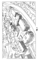
- FIG. 2 illustrates a portion of the computerized 3D model depicted in FIG. 1 zoomed in such that the textures are pixilated.
- FIG. 3 illustrates a portion of the computerized 3D model depicted in FIG. 1 with one particular building texture highlighted and outlined using an edge detection algorithm.
- FIG. 4 illustrates a palette of building materials in accordance with the present invention, showing their numeric match value in relation to the selected building texture of FIG. 3 , with the highest score highlighted.
- FIG. 5 illustrates the computerized 3D model depicted in FIG. 3 with a real world texture replaced with a simulated texture in accordance with the present invention, and building material properties in a table off to the side.
- FIG. 6 illustrates a portion of the computerized 3D model depicted in FIG. 1 with the real world and simulated textures combined in accordance with the present invention.
- FIG. 6 a is a zoomed in diagram of the model depicted in FIG. 6 .
- FIG. 7 illustrates a portion of the computerized 3D model depicted in FIG. 1 with two particular windows highlighted and outlined using an edge detection algorithm in accordance with the present invention.
- FIG. 8 illustrates an exemplary palette of images representing a portion of a physical object, e.g. representative of types of glass, with a numeric match value in relation to the selected windows of FIG. 7 , with the highest score highlighted.
- FIG. 9 illustrates the computerized 3D model depicted in FIG. 1 with the images of the real world windows replaced with their simulated versions.
- FIG. 10 illustrates a blast analysis model inside a 3D model.
- FIG. 11 is a block diagram of a computer system as used in the present invention.
- the presently claimed and disclosed invention(s) relate to a material property determination system, and an automated method of assigning material properties to image textures within a 3D model. More particularly, but not by way of limitation, the presently claimed and disclosed invention(s) uses an automated methodology to determine and assign material properties to images textures applied to the 3D model by comparing each image texture to entries in a palette of images representing material entries and assigning the image representing the material palette entry that best matches the one contained in the 3D model image texture.
- texture refers to an image, e.g., a digital image, representing a surface, a material, a pattern or even a picture.
- the texture can be created in a variety of manners, such as being generated from a captured or projected image, or generated by an artist or a designer using a bitmap editor software such as Adobe® Photoshop® or Gimp or by scanning an image and, if necessary or desirable, retouching, color balancing, or otherwise processing it on a computer such as a personal computer, dedicated server or the like.
- the texture can be in a suitable format, such as a bitmap format, or a vector format.
- the texture can be built as a large image, larger than the final destination (such as page, for example) so as to fill the complete area without repeating the image (thus avoiding visible seams).
- bitmap textures can be created to be used as repetitive patterns to fill an infinite area. The borders of these patterns or small textures should be treated to give a seamless appearance when applied to an image, unless, of course, the seam is something to be shown.
- the textures should be created in high-resolution in order to achieve good results in the final print.
- textures When the textures are meant to be used in multimedia, a 3d model or web design, they should be created in a maximum resolution that equals the one of the final display (TV, computer monitor, movie projector, etc.).
- palette of material entries means a given, finite set of textures representative of material properties of physical materials.
- each material palette entry represents a particular type of physical material.
- the material palette entry that best matches a particular image texture in the computerized 3D model is assigned to the image texture to indicate a material property of the physical object represented by the 3D model.
- 3D model is a collection of data that represent a 3-dimensional object using a collection of points in 3D space, connected by various geometric entities such as triangles, lines, curved surfaces, etc. The geometric entities are sometimes called “wireframes” in the art.
- the 3D model can be created manually or automatically.
- One exemplary method for creating a 3D model is described in a United States patent application identified by U.S. Ser. No. 11/998,974 titled “SYSTEMS AND METHODS FOR RAPID THREE-DIMENSIONAL MODELING WITH REAL FACADE TEXTURE,” the entire contents of which are herein incorporated by reference.
- the 3D model can be constructed in various manners, such as solid or shell, and can either be a stationary 3D model or animated.
- the present invention is directed to a method of automatically transforming a computerized 3D model having portions of images utilized as textures on one or more physical objects represented in the 3D model to include material property information for one or more regions of the textures of the 3D model. See FIG. 1 as an example of such a 3D model having portions of images utilized as textures of one or more physical objects represented in the 3D model.
- image textures applied to the 3D model are examined by comparing, utilizing a computer system 50 (see FIG. 11 as described below), at least a portion of each image texture to entries in a palette of material entries.
- the material palette entry that best matches the one contained in the image texture is assigned to the image texture to indicate a physical material of the physical object represented by the 3D model. Then, material property information is stored in the computerized 3D model for the image textures that are assigned a material palette entry.
- the entries in the material palette can be modified such that their image resolution matches the image resolution contained in the 3D model image textures prior to comparison.
- the material property information stored in the computerized 3D model can be stored in fields in the computerized 3D model data directly, or a unique identifier for the selected material palette entry, or an address to information where the selected material palette entry (or material property) is stored or identified, or other information associated with a material palette entry can be stored in the 3D model data and is subsequently used to retrieve the material property or structural element information from a list or database of material properties.
- material property or structural element information can be stored as metadata within the 3D model, either appended to the same file or in another file readily accessible (an industry standard practice is to use the same filename but with a different file extension).
- the entries in the palette of material entries can be utilized to texture one or more of the image textures representing the physical objects within the computerized 3D model. That is, once the material palette entry that best matches the image texture is assigned to indicate a physical material of the physical object represented by the 3D model, the material palette entry can be utilized as a simulated texture to replace or enhance the image texture of one or more physical objects represented in the 3D model.
- the presently disclosed and claimed invention would provide the method to do material classification using color imagery (e.g., red, green, and blue color bands) through the use of oblique images.
- color imagery e.g., red, green, and blue color bands
- the color oblique imagery is utilized to provide initial image textures for the 3D models and then a palette of possible building materials is compared to the image texture within the 3D model to automatically assign material properties to the portions of the image textures contained within the 3D model representing the physical objects, e.g., the buildings.
- These methods also provide a means to automatically size and position simulated textures of structural elements, e.g., windows, doors or the like, on the 3D model based on those detected in the actual imagery of textures representing the buildings.
- This methodology offers a number of advantages.
- Second, the method of the present invention is highly automated, requiring only quality control and clean up of any false identifications. Third, by assigning building material properties to the palette of available materials, the resulting 3D model can be used for blast simulations and other analyses that require knowledge of the material composition in the model.
- the entry from the material palette can replace the actual oblique image texture in the 3D model, thereby greatly reducing the data content in the scene.
- the entry from the material palette can be used to produce higher resolution textures of the building than is possible from the original imagery.
- the primary methodology includes the step of comparing a particular building texture with one or more, and preferably each, of the entries in the material palette and then selecting the entry with the best match.
- the entries in the material palette can optionally be pixilated to match the resolution of the actual texture in the 3D model representing the building.
- FIG. 2 shows a portion of a building 20 shown in FIG. 1 wherein the image is zoomed in to illustrate the pixilation that can occur with differing resolutions of images. This will help make sure that the algorithm is not confused by differences in resolution and differences in patterns caused by the differing resolution.
- a secondary optional methodology will use an edge detection algorithm to analyze the textures within the 3D model to locate representations of predetermined structural elements, such as structural features, windows and doors, or the absence of a predetermined structural element, such as a void or a hole.
- FIGS. 3 and 7 illustrate a structural feature (building surface 22 in FIG. 3 ) and windows 24 ( FIG. 7 ) as detected and outlined by the edge detection algorithm.
- the material information or structural element information added to the 3D model in accordance with the present invention can be stored in fields in the computerized 3D model data directly, or one or more unique identifier(s) for the material or structural element information can be added, or an address to information where the material or structural element information is stored or identified, or other information associated with a material palette entry or structural element entry can be stored in the 3D model data and subsequently used to retrieve the material property information or structural element information from a list or database of material properties.
- the textures and the entries in the palettes can be stored in any format; including one of many industry standard image formats such as TIFF, JFIF, TARGA, Windows Bitmap File, PNG or any other industry standard format.
- FIGS. 4 and 8 illustrate such palette entries wherein the image textures selected and outlined in FIGS. 3 and 7 (building surface 22 in FIG. 3 or windows 24 in FIG. 7 ) have been compared to the palette entries and the resulting comparison value is indicated next to each palette entry. As would be understood, the palette entry with the highest comparison value would be selected as the palette entry which corresponds to the selected image textures of FIGS. 3 and 7 .
- a further methodology of the present invention permits the application of the texture contained in the palette entries corresponding to the selected image textures to the 3D model so as to improve the useable resolution of the 3D model.
- the application of the palette texture to the 3D model of the structure would permit a user of the present methodology to zoom in to the particular structure, e.g., the building 20 of FIG. 2 , represented within the 3D model without the pixilation that would be normally be present.
- FIGS. 5 and 9 illustrate the application of the palette textures to the selected and outlined image textures of FIGS. 3 and 7 (building surface 22 in FIG. 3 or windows 24 in FIG. 7 ).
- FIG. 6 illustrates the building 20 shown in FIG. 2 wherein the original digital oblique image applied to and representing the building within the 3D model has been completely replaced by the palette texture as described above.
- FIG. 6 a illustrates the same building 20 zoomed in so as to show the palette texture in greater detail. As can be seen, the zoomed in image shown in FIG. 6 a is free from the normal pixilation as shown in the zoomed in image of FIG. 2 .
- the selected and outlined image textures would also be assigned the material properties associated with the palette entry corresponding to the image texture.
- the image texture replaced by the palette texture would also include the associated material properties.
- the output model could also be loaded into an analysis tool such as Lockheed Martin's TOPSCENE with a plurality of threat domes 40 (shown individually as 40 a - 40 e ) overlaid on top of the 3D model.
- Building material attribution, i.e., consideration of the building material properties, on the 3D model would increase the predictive capability of a blast or ballistic penetration analysis.
- Threat domes 40 a - 40 e would be understood to vary in size depending on the building material property assigned to a particular building for a given blast penetration analysis. That is, an analysis tool could take the material property assigned to structure(s) into consideration when analyzing different scenarios, e.g., a blast scenario, in order to provide improved predictive capabilities. For example, a blast occurring inside a structure constructed with glass walls would readily be understood to result in a different blast scenario than a similar blast occurring inside a structure constructed with brick walls.
- FIG. 11 illustrates a block diagram of an exemplary embodiment of a computer system 50 constructed in accordance with the present invention.
- the computer system 50 includes a processor 52 in communication with a computer readable medium 56 , an input/output interface 54 and a communication interface 58 .
- the input/output interface 54 is further in communication with input/output devices 62 a - d .
- the computer system 50 can further utilize additional input/output devices (not shown) which would permit a user to enter, process and produce an output of a 3D model constructed in accordance with the present invention.
- the computer system 50 could further include a digital tablet, an optical scanner, an external computer readable medium and the like.
- the communication interface 58 is in communication with communication network 60 .
- Communication network 60 provides a mechanism for the computer system 50 to transmit and/or receive information between the computer system 50 and external devices/systems, such as digital images, 3D models and the like.
- Communication network 60 can be implemented using any commonly available communication mediums, such as wireless, wired, TCP/IP, fiber optic and the like.
- Computer readable medium 56 permits storage and retrieval of digital information (data) and also computer executable code as utilized in the present invention.
- Examples of a computer readable medium 56 include an optical storage device, a magnetic storage device, an electronic storage device or the like.
- Computer System means a system or systems that are able to embody and/or execute the logic of the processes described herein.
- the logic embodied in the form of software instructions or firmware may be executed on any appropriate hardware which may be a dedicated system or systems, or a general purpose computer system, or distributed processing computer system, all of which are well understood in the art, and a detailed description of how to make or use such computers is not deemed necessary herein.
- the computer system is used to execute the logic of the processes described herein, such computer(s) and/or execution can be conducted at a same geographic location or multiple different geographic locations.
- the execution of the logic can be conducted continuously or at multiple discrete times. Further, such logic can be performed about simultaneously with the capture of the images, or thereafter or combinations thereof.
Abstract
Description
-
- 1. Captured Imagery—these images have the appearance they were captured by the camera or sensor employed.
- 2. Projected Imagery—these images have been processed and converted such that they conform to a mathematical projection.
Claims (20)
Priority Applications (15)
| Application Number | Priority Date | Filing Date | Title |
|---|---|---|---|
| US12/605,980 US9330494B2 (en) | 2009-10-26 | 2009-10-26 | Method for the automatic material classification and texture simulation for 3D models |
| ES10828764T ES2780174T3 (en) | 2009-10-26 | 2010-10-18 | A procedure for automatic material classification and texture simulation for 3D models |
| EP10828764.0A EP2494525B1 (en) | 2009-10-26 | 2010-10-18 | A method for automatic material classification and texture simulation for 3d models |
| PCT/US2010/053052 WO2011056402A2 (en) | 2009-10-26 | 2010-10-18 | A method for automatic material classification and texture simulation for 3d models |
| CA2778267A CA2778267C (en) | 2009-10-26 | 2010-10-18 | A method for automatic material classification and texture simulation for 3d models |
| EP20154391.5A EP3693931A1 (en) | 2009-10-26 | 2010-10-18 | Method for the automatic material classification and texture simulation for 3d models |
| AU2010315698A AU2010315698B2 (en) | 2009-10-26 | 2010-10-18 | A method for automatic material classification and texture simulation for 3D models |
| BR112012009880A BR112012009880A2 (en) | 2009-10-26 | 2010-10-18 | "method for automatic material classification and texture simulation for 3d models" |
| AU2015275308A AU2015275308B2 (en) | 2009-10-26 | 2015-12-23 | A method for automatic material classification and texture simulation for 3d models |
| US15/142,361 US9959667B2 (en) | 2009-10-26 | 2016-04-29 | Method for the automatic material classification and texture simulation for 3D models |
| US15/964,956 US10198857B2 (en) | 2009-10-26 | 2018-04-27 | Method for the automatic material classification and texture simulation for 3D models |
| AU2018204115A AU2018204115B2 (en) | 2009-10-26 | 2018-06-08 | A method for automatic material classification and texture simulation for 3d models |
| US16/266,896 US10748335B2 (en) | 2009-10-26 | 2019-02-04 | Method for the automatic material classification and texture simulation for 3D models |
| US16/994,914 US11263807B2 (en) | 2009-10-26 | 2020-08-17 | Method for the automatic material classification and texture simulation for 3D models |
| US17/682,513 US11657567B2 (en) | 2009-10-26 | 2022-02-28 | Method for the automatic material classification and texture simulation for 3D models |
Applications Claiming Priority (1)
| Application Number | Priority Date | Filing Date | Title |
|---|---|---|---|
| US12/605,980 US9330494B2 (en) | 2009-10-26 | 2009-10-26 | Method for the automatic material classification and texture simulation for 3D models |
Related Child Applications (1)
| Application Number | Title | Priority Date | Filing Date |
|---|---|---|---|
| US15/142,361 Continuation US9959667B2 (en) | 2009-10-26 | 2016-04-29 | Method for the automatic material classification and texture simulation for 3D models |
Publications (2)
| Publication Number | Publication Date |
|---|---|
| US20110096083A1 US20110096083A1 (en) | 2011-04-28 |
| US9330494B2 true US9330494B2 (en) | 2016-05-03 |
Family
ID=43898043
Family Applications (6)
| Application Number | Title | Priority Date | Filing Date |
|---|---|---|---|
| US12/605,980 Active 2031-12-02 US9330494B2 (en) | 2009-10-26 | 2009-10-26 | Method for the automatic material classification and texture simulation for 3D models |
| US15/142,361 Active US9959667B2 (en) | 2009-10-26 | 2016-04-29 | Method for the automatic material classification and texture simulation for 3D models |
| US15/964,956 Active US10198857B2 (en) | 2009-10-26 | 2018-04-27 | Method for the automatic material classification and texture simulation for 3D models |
| US16/266,896 Active US10748335B2 (en) | 2009-10-26 | 2019-02-04 | Method for the automatic material classification and texture simulation for 3D models |
| US16/994,914 Active US11263807B2 (en) | 2009-10-26 | 2020-08-17 | Method for the automatic material classification and texture simulation for 3D models |
| US17/682,513 Active US11657567B2 (en) | 2009-10-26 | 2022-02-28 | Method for the automatic material classification and texture simulation for 3D models |
Family Applications After (5)
| Application Number | Title | Priority Date | Filing Date |
|---|---|---|---|
| US15/142,361 Active US9959667B2 (en) | 2009-10-26 | 2016-04-29 | Method for the automatic material classification and texture simulation for 3D models |
| US15/964,956 Active US10198857B2 (en) | 2009-10-26 | 2018-04-27 | Method for the automatic material classification and texture simulation for 3D models |
| US16/266,896 Active US10748335B2 (en) | 2009-10-26 | 2019-02-04 | Method for the automatic material classification and texture simulation for 3D models |
| US16/994,914 Active US11263807B2 (en) | 2009-10-26 | 2020-08-17 | Method for the automatic material classification and texture simulation for 3D models |
| US17/682,513 Active US11657567B2 (en) | 2009-10-26 | 2022-02-28 | Method for the automatic material classification and texture simulation for 3D models |
Country Status (7)
| Country | Link |
|---|---|
| US (6) | US9330494B2 (en) |
| EP (2) | EP3693931A1 (en) |
| AU (1) | AU2010315698B2 (en) |
| BR (1) | BR112012009880A2 (en) |
| CA (1) | CA2778267C (en) |
| ES (1) | ES2780174T3 (en) |
| WO (1) | WO2011056402A2 (en) |
Cited By (7)
| Publication number | Priority date | Publication date | Assignee | Title |
|---|---|---|---|---|
| US20140294147A1 (en) * | 2013-03-15 | 2014-10-02 | Varian Medical Systems, Inc. | Systems and methods for multi-view imaging and tomography |
| WO2017213742A1 (en) * | 2016-06-08 | 2017-12-14 | Qualcomm Incorporated | Material-aware three-dimensional scanning |
| US10529029B2 (en) | 2016-09-23 | 2020-01-07 | Aon Benfield Inc. | Platform, systems, and methods for identifying property characteristics and property feature maintenance through aerial imagery analysis |
| US10650285B1 (en) | 2016-09-23 | 2020-05-12 | Aon Benfield Inc. | Platform, systems, and methods for identifying property characteristics and property feature conditions through aerial imagery analysis |
| US11222464B2 (en) | 2019-08-22 | 2022-01-11 | The Travelers Indemnity Company | Intelligent imagery |
| US11514644B2 (en) | 2018-01-19 | 2022-11-29 | Enphase Energy, Inc. | Automated roof surface measurement from combined aerial LiDAR data and imagery |
| US20230081263A1 (en) * | 2021-09-16 | 2023-03-16 | Hangzhou Tianyan Zhilian Technology Co., Ltd. | Methods, Devices, and Systems for Identifying the Composition of Materials |
Families Citing this family (54)
| Publication number | Priority date | Publication date | Assignee | Title |
|---|---|---|---|---|
| US8078436B2 (en) | 2007-04-17 | 2011-12-13 | Eagle View Technologies, Inc. | Aerial roof estimation systems and methods |
| US8145578B2 (en) | 2007-04-17 | 2012-03-27 | Eagel View Technologies, Inc. | Aerial roof estimation system and method |
| US8209152B2 (en) | 2008-10-31 | 2012-06-26 | Eagleview Technologies, Inc. | Concurrent display systems and methods for aerial roof estimation |
| US8170840B2 (en) | 2008-10-31 | 2012-05-01 | Eagle View Technologies, Inc. | Pitch determination systems and methods for aerial roof estimation |
| US8731234B1 (en) | 2008-10-31 | 2014-05-20 | Eagle View Technologies, Inc. | Automated roof identification systems and methods |
| US9330494B2 (en) * | 2009-10-26 | 2016-05-03 | Pictometry International Corp. | Method for the automatic material classification and texture simulation for 3D models |
| WO2011094760A2 (en) | 2010-02-01 | 2011-08-04 | Eagle View Technologies | Geometric correction of rough wireframe models derived from photographs |
| US9741156B2 (en) | 2011-09-08 | 2017-08-22 | Microsoft Technology Licensing, Llc. | Material trouble shooter |
| US9970890B2 (en) * | 2011-10-20 | 2018-05-15 | Varex Imaging Corporation | Method and apparatus pertaining to non-invasive identification of materials |
| US20130185024A1 (en) * | 2012-01-12 | 2013-07-18 | Honeywell International Inc. | System for automatic object classification and tagging in an rf planning tool |
| US10663294B2 (en) | 2012-02-03 | 2020-05-26 | Eagle View Technologies, Inc. | Systems and methods for estimation of building wall area and producing a wall estimation report |
| US9933257B2 (en) | 2012-02-03 | 2018-04-03 | Eagle View Technologies, Inc. | Systems and methods for estimation of building wall area |
| US8774525B2 (en) | 2012-02-03 | 2014-07-08 | Eagle View Technologies, Inc. | Systems and methods for estimation of building floor area |
| US9599466B2 (en) | 2012-02-03 | 2017-03-21 | Eagle View Technologies, Inc. | Systems and methods for estimation of building wall area |
| US10515414B2 (en) | 2012-02-03 | 2019-12-24 | Eagle View Technologies, Inc. | Systems and methods for performing a risk management assessment of a property |
| US9501700B2 (en) | 2012-02-15 | 2016-11-22 | Xactware Solutions, Inc. | System and method for construction estimation using aerial images |
| US9396577B2 (en) * | 2012-02-16 | 2016-07-19 | Google Inc. | Using embedded camera parameters to determine a position for a three-dimensional model |
| US8462155B1 (en) | 2012-05-01 | 2013-06-11 | Google Inc. | Merging three-dimensional models based on confidence scores |
| US8884955B1 (en) | 2012-05-04 | 2014-11-11 | Google Inc. | Surface simplification based on offset tiles |
| US9041711B1 (en) | 2012-05-08 | 2015-05-26 | Google Inc. | Generating reduced resolution textured model from higher resolution model |
| US8897543B1 (en) | 2012-05-18 | 2014-11-25 | Google Inc. | Bundle adjustment based on image capture intervals |
| US8965107B1 (en) | 2012-05-18 | 2015-02-24 | Google Inc. | Feature reduction based on local densities for bundle adjustment of images |
| US8941652B1 (en) | 2012-05-23 | 2015-01-27 | Google Inc. | Incremental surface hole filling |
| US9224233B2 (en) | 2012-05-24 | 2015-12-29 | Google Inc. | Blending 3D model textures by image projection |
| US8463024B1 (en) | 2012-05-25 | 2013-06-11 | Google Inc. | Combining narrow-baseline and wide-baseline stereo for three-dimensional modeling |
| US11587176B2 (en) | 2013-03-15 | 2023-02-21 | Eagle View Technologies, Inc. | Price estimation model |
| US9753950B2 (en) * | 2013-03-15 | 2017-09-05 | Pictometry International Corp. | Virtual property reporting for automatic structure detection |
| US10909482B2 (en) | 2013-03-15 | 2021-02-02 | Pictometry International Corp. | Building materials estimation |
| US9959581B2 (en) | 2013-03-15 | 2018-05-01 | Eagle View Technologies, Inc. | Property management on a smartphone |
| WO2015017855A1 (en) | 2013-08-02 | 2015-02-05 | Xactware Solutions, Inc. | System and method for detecting features in aerial images using disparity mapping and segmentation techniques |
| US20150095071A1 (en) | 2013-09-29 | 2015-04-02 | Donan Engineering Co., Inc. | Systems and Methods for Identifying a Subrogation Opportunity for a Potential Subrogation Claim |
| US10108755B2 (en) * | 2013-11-19 | 2018-10-23 | Aerohive Networks, Inc. | RF floor plan building |
| US10809699B2 (en) | 2015-04-24 | 2020-10-20 | Hewlett-Packard Development Company, L.P. | Method for generating three dimensional object models for an additive manufacturing process |
| US9798841B2 (en) * | 2015-09-15 | 2017-10-24 | Livermore Software Technology Corp. | Systems and methods of conducting numerical simulation of an underwater explosion |
| US10832333B1 (en) | 2015-12-11 | 2020-11-10 | State Farm Mutual Automobile Insurance Company | Structural characteristic extraction using drone-generated 3D image data |
| US9823658B1 (en) | 2016-11-04 | 2017-11-21 | Loveland Innovations, LLC | Systems and methods for adaptive property analysis via autonomous vehicles |
| US10521664B2 (en) | 2016-11-04 | 2019-12-31 | Loveland Innovations, LLC | Systems and methods for autonomous perpendicular imaging of test squares |
| US11354013B1 (en) * | 2017-02-17 | 2022-06-07 | Skydio, Inc. | Location-based asset efficiency determination |
| US10984182B2 (en) | 2017-05-12 | 2021-04-20 | Loveland Innovations, LLC | Systems and methods for context-rich annotation and report generation for UAV microscan data |
| US10364027B2 (en) | 2017-10-24 | 2019-07-30 | Loveland Innovations, LLC | Crisscross boustrophedonic flight patterns for UAV scanning and imaging |
| US10503843B2 (en) | 2017-12-19 | 2019-12-10 | Eagle View Technologies, Inc. | Supervised automatic roof modeling |
| CN109085780B (en) * | 2018-08-03 | 2021-06-04 | 厦门大学 | Experimental instrument control system and method based on Unity3D |
| US10366287B1 (en) | 2018-08-24 | 2019-07-30 | Loveland Innovations, LLC | Image analysis and estimation of rooftop solar exposure |
| US11205072B2 (en) | 2018-08-24 | 2021-12-21 | Loveland Innovations, LLC | Solar ray mapping via divergent beam modeling |
| US11210514B2 (en) | 2018-08-24 | 2021-12-28 | Loveland Innovations, LLC | Image analysis and estimation of rooftop solar exposure via solar ray mapping |
| CN112100367A (en) * | 2019-05-28 | 2020-12-18 | 贵阳海信网络科技有限公司 | Public opinion early warning method and device for scenic spot |
| KR102197724B1 (en) * | 2019-07-15 | 2021-01-04 | 현대자동차주식회사 | Apparatus for crashworthiness prediction and method thereof |
| US11521026B2 (en) | 2019-10-21 | 2022-12-06 | Bentley Systems, Incorporated | Classifying individual elements of an infrastructure model |
| US11094113B2 (en) | 2019-12-04 | 2021-08-17 | Geomni, Inc. | Systems and methods for modeling structures using point clouds derived from stereoscopic image pairs |
| US11734890B2 (en) * | 2020-08-17 | 2023-08-22 | Nvidia Corporation | Three-dimensional model recovery from two-dimensional images |
| US11645363B2 (en) | 2020-10-20 | 2023-05-09 | Bentley Systems, Incorporated | Automatic identification of misclassified elements of an infrastructure model |
| US11532116B2 (en) | 2020-10-30 | 2022-12-20 | Loveland Innovations, Inc. | Graphical user interface for controlling a solar ray mapping |
| US20220244833A1 (en) * | 2021-01-22 | 2022-08-04 | Primitive LLC | Interactive 3d roof model |
| US11694400B2 (en) * | 2021-06-03 | 2023-07-04 | Shopify Inc. | Systems and methods for supplementing digital media with three-dimensional (3D) models |
Citations (170)
| Publication number | Priority date | Publication date | Assignee | Title |
|---|---|---|---|---|
| US2273876A (en) | 1940-02-12 | 1942-02-24 | Frederick W Lutz | Apparatus for indicating tilt of cameras |
| US3153784A (en) | 1959-12-24 | 1964-10-20 | Us Industries Inc | Photo radar ground contour mapping system |
| US3594556A (en) | 1969-01-08 | 1971-07-20 | Us Navy | Optical sight with electronic image stabilization |
| US3614410A (en) | 1969-06-12 | 1971-10-19 | Knight V Bailey | Image rectifier |
| US3621326A (en) | 1968-09-30 | 1971-11-16 | Itek Corp | Transformation system |
| US3661061A (en) | 1969-05-05 | 1972-05-09 | Atomic Energy Commission | Picture position finder |
| US3716669A (en) | 1971-05-14 | 1973-02-13 | Japan Eng Dev Co | Mapping rectifier for generating polarstereographic maps from satellite scan signals |
| US3725563A (en) | 1971-12-23 | 1973-04-03 | Singer Co | Method of perspective transformation in scanned raster visual display |
| US3864513A (en) | 1972-09-11 | 1975-02-04 | Grumman Aerospace Corp | Computerized polarimetric terrain mapping system |
| US3866602A (en) | 1973-05-29 | 1975-02-18 | Olympus Optical Co | Endoscope camera with orientation indicator |
| US3877799A (en) | 1974-02-06 | 1975-04-15 | United Kingdom Government | Method of recording the first frame in a time index system |
| US4015080A (en) | 1973-04-30 | 1977-03-29 | Elliott Brothers (London) Limited | Display devices |
| US4044879A (en) | 1975-03-07 | 1977-08-30 | Siemens Aktiengesellschaft | Arrangement for recording characters using mosaic recording mechanisms |
| US4184711A (en) | 1977-10-14 | 1980-01-22 | Yasuo Wakimoto | Folding canvas chair |
| US4240108A (en) | 1977-10-03 | 1980-12-16 | Grumman Aerospace Corporation | Vehicle controlled raster display system |
| US4281354A (en) | 1978-05-19 | 1981-07-28 | Raffaele Conte | Apparatus for magnetic recording of casual events relating to movable means |
| US4344683A (en) | 1979-09-29 | 1982-08-17 | Agfa-Gevaert Aktiengesellschaft | Quality control method and apparatus for photographic pictures |
| US4360876A (en) | 1979-07-06 | 1982-11-23 | Thomson-Csf | Cartographic indicator system |
| US4382678A (en) | 1981-06-29 | 1983-05-10 | The United States Of America As Represented By The Secretary Of The Army | Measuring of feature for photo interpretation |
| US4387056A (en) | 1981-04-16 | 1983-06-07 | E. I. Du Pont De Nemours And Company | Process for separating zero-valent nickel species from divalent nickel species |
| US4396942A (en) | 1979-04-19 | 1983-08-02 | Jackson Gates | Video surveys |
| US4463380A (en) | 1981-09-25 | 1984-07-31 | Vought Corporation | Image processing system |
| US4489322A (en) | 1983-01-27 | 1984-12-18 | The United States Of America As Represented By The Secretary Of The Air Force | Radar calibration using direct measurement equipment and oblique photometry |
| US4490742A (en) | 1982-04-23 | 1984-12-25 | Vcs, Incorporated | Encoding apparatus for a closed circuit television system |
| US4491399A (en) | 1982-09-27 | 1985-01-01 | Coherent Communications, Inc. | Method and apparatus for recording a digital signal on motion picture film |
| US4495500A (en) | 1982-01-26 | 1985-01-22 | Sri International | Topographic data gathering method |
| US4527055A (en) | 1982-11-15 | 1985-07-02 | Honeywell Inc. | Apparatus for selectively viewing either of two scenes of interest |
| US4543603A (en) | 1982-11-30 | 1985-09-24 | Societe Nationale Industrielle Et Aerospatiale | Reconnaissance system comprising an air-borne vehicle rotating about its longitudinal axis |
| US4586138A (en) | 1982-07-29 | 1986-04-29 | The United States Of America As Represented By The United States Department Of Energy | Route profile analysis system and method |
| US4635136A (en) | 1984-02-06 | 1987-01-06 | Rochester Institute Of Technology | Method and apparatus for storing a massive inventory of labeled images |
| US4653136A (en) | 1985-06-21 | 1987-03-31 | Denison James W | Wiper for rear view mirror |
| US4653316A (en) | 1986-03-14 | 1987-03-31 | Kabushiki Kaisha Komatsu Seisakusho | Apparatus mounted on vehicles for detecting road surface conditions |
| US4673988A (en) | 1985-04-22 | 1987-06-16 | E.I. Du Pont De Nemours And Company | Electronic mosaic imaging process |
| US4686474A (en) | 1984-04-05 | 1987-08-11 | Deseret Research, Inc. | Survey system for collection and real time processing of geophysical data |
| US4688092A (en) | 1986-05-06 | 1987-08-18 | Ford Aerospace & Communications Corporation | Satellite camera image navigation |
| US4689748A (en) | 1979-10-09 | 1987-08-25 | Messerschmitt-Bolkow-Blohm Gesellschaft Mit Beschrankter Haftung | Device for aircraft and spacecraft for producing a digital terrain representation |
| US4707698A (en) | 1976-03-04 | 1987-11-17 | Constant James N | Coordinate measurement and radar device using image scanner |
| US4758850A (en) | 1985-08-01 | 1988-07-19 | British Aerospace Public Limited Company | Identification of ground targets in airborne surveillance radar returns |
| US4805033A (en) | 1987-02-18 | 1989-02-14 | Olympus Optical Co., Ltd. | Method of forming oblique dot pattern |
| US4807024A (en) | 1987-06-08 | 1989-02-21 | The University Of South Carolina | Three-dimensional display methods and apparatus |
| US4814896A (en) | 1987-03-06 | 1989-03-21 | Heitzman Edward F | Real time video data acquistion systems |
| US4814711A (en) | 1984-04-05 | 1989-03-21 | Deseret Research, Inc. | Survey system and method for real time collection and processing of geophysicals data using signals from a global positioning satellite network |
| US4843463A (en) | 1988-05-23 | 1989-06-27 | Michetti Joseph A | Land vehicle mounted audio-visual trip recorder |
| US4899296A (en) | 1987-11-13 | 1990-02-06 | Khattak Anwar S | Pavement distress survey system |
| US4906198A (en) | 1988-12-12 | 1990-03-06 | International Business Machines Corporation | Circuit board assembly and contact pin for use therein |
| US4953227A (en) | 1986-01-31 | 1990-08-28 | Canon Kabushiki Kaisha | Image mosaic-processing method and apparatus |
| US4956872A (en) | 1986-10-31 | 1990-09-11 | Canon Kabushiki Kaisha | Image processing apparatus capable of random mosaic and/or oil-painting-like processing |
| US5034812A (en) | 1988-11-14 | 1991-07-23 | Smiths Industries Public Limited Company | Image processing utilizing an object data store to determine information about a viewed object |
| US5086314A (en) | 1990-05-21 | 1992-02-04 | Nikon Corporation | Exposure control apparatus for camera |
| US5121222A (en) | 1989-06-14 | 1992-06-09 | Toshiaki Endoh | Method and apparatus for producing binary picture with detection and retention of plural binary picture blocks having a thin line pattern including an oblique line |
| US5138444A (en) | 1991-09-05 | 1992-08-11 | Nec Corporation | Image pickup system capable of producing correct image signals of an object zone |
| US5155597A (en) | 1990-11-28 | 1992-10-13 | Recon/Optical, Inc. | Electro-optical imaging array with motion compensation |
| US5164825A (en) | 1987-03-30 | 1992-11-17 | Canon Kabushiki Kaisha | Image processing method and apparatus for mosaic or similar processing therefor |
| US5166789A (en) | 1989-08-25 | 1992-11-24 | Space Island Products & Services, Inc. | Geographical surveying using cameras in combination with flight computers to obtain images with overlaid geographical coordinates |
| US5191174A (en) | 1990-08-01 | 1993-03-02 | International Business Machines Corporation | High density circuit board and method of making same |
| US5200793A (en) | 1990-10-24 | 1993-04-06 | Kaman Aerospace Corporation | Range finding array camera |
| US5210586A (en) | 1990-06-27 | 1993-05-11 | Siemens Aktiengesellschaft | Arrangement for recognizing obstacles for pilots of low-flying aircraft |
| US5231435A (en) | 1991-07-12 | 1993-07-27 | Blakely Bruce W | Aerial camera mounting apparatus |
| US5247356A (en) | 1992-02-14 | 1993-09-21 | Ciampa John A | Method and apparatus for mapping and measuring land |
| US5251037A (en) | 1992-02-18 | 1993-10-05 | Hughes Training, Inc. | Method and apparatus for generating high resolution CCD camera images |
| US5265173A (en) | 1991-03-20 | 1993-11-23 | Hughes Aircraft Company | Rectilinear object image matcher |
| US5267042A (en) | 1991-01-11 | 1993-11-30 | Pioneer Electronic Corporation | Image pickup device for automatically recording the location where an image is recorded |
| US5270756A (en) | 1992-02-18 | 1993-12-14 | Hughes Training, Inc. | Method and apparatus for generating high resolution vidicon camera images |
| US5296884A (en) | 1990-02-23 | 1994-03-22 | Minolta Camera Kabushiki Kaisha | Camera having a data recording function |
| US5335072A (en) | 1990-05-30 | 1994-08-02 | Minolta Camera Kabushiki Kaisha | Photographic system capable of storing information on photographed image data |
| US5342999A (en) | 1992-12-21 | 1994-08-30 | Motorola, Inc. | Apparatus for adapting semiconductor die pads and method therefor |
| US5345086A (en) | 1962-11-28 | 1994-09-06 | Eaton Corporation | Automatic map compilation system |
| US5353055A (en) | 1991-04-16 | 1994-10-04 | Nec Corporation | Image pickup system with an image pickup device for control |
| US5369443A (en) | 1991-04-12 | 1994-11-29 | Abekas Video Systems, Inc. | Digital video effects generator |
| US5402170A (en) | 1991-12-11 | 1995-03-28 | Eastman Kodak Company | Hand-manipulated electronic camera tethered to a personal computer |
| US5414462A (en) | 1993-02-11 | 1995-05-09 | Veatch; John W. | Method and apparatus for generating a comprehensive survey map |
| US5467271A (en) | 1993-12-17 | 1995-11-14 | Trw, Inc. | Mapping and analysis system for precision farming applications |
| US5481479A (en) | 1992-12-10 | 1996-01-02 | Loral Fairchild Corp. | Nonlinear scanning to optimize sector scan electro-optic reconnaissance system performance |
| US5486948A (en) | 1989-03-24 | 1996-01-23 | Canon Hanbai Kabushiki Kaisha | Stereo image forming apparatus having a light deflection member in each optical path |
| US5506644A (en) | 1992-08-18 | 1996-04-09 | Olympus Optical Co., Ltd. | Camera |
| US5508736A (en) | 1993-05-14 | 1996-04-16 | Cooper; Roger D. | Video signal processing apparatus for producing a composite signal for simultaneous display of data and video information |
| US5555018A (en) | 1991-04-25 | 1996-09-10 | Von Braun; Heiko S. | Large-scale mapping of parameters of multi-dimensional structures in natural environments |
| US5604534A (en) | 1995-05-24 | 1997-02-18 | Omni Solutions International, Ltd. | Direct digital airborne panoramic camera system and method |
| US5617224A (en) | 1989-05-08 | 1997-04-01 | Canon Kabushiki Kaisha | Imae processing apparatus having mosaic processing feature that decreases image resolution without changing image size or the number of pixels |
| US5633946A (en) | 1994-05-19 | 1997-05-27 | Geospan Corporation | Method and apparatus for collecting and processing visual and spatial position information from a moving platform |
| US5668593A (en) | 1995-06-07 | 1997-09-16 | Recon/Optical, Inc. | Method and camera system for step frame reconnaissance with motion compensation |
| US5677515A (en) | 1991-10-18 | 1997-10-14 | Trw Inc. | Shielded multilayer printed wiring board, high frequency, high isolation |
| US5798786A (en) | 1996-05-07 | 1998-08-25 | Recon/Optical, Inc. | Electro-optical imaging detector array for a moving vehicle which includes two axis image motion compensation and transfers pixels in row directions and column directions |
| US5835133A (en) | 1996-01-23 | 1998-11-10 | Silicon Graphics, Inc. | Optical system for single camera stereo video |
| US5841574A (en) | 1996-06-28 | 1998-11-24 | Recon/Optical, Inc. | Multi-special decentered catadioptric optical system |
| US5844602A (en) | 1996-05-07 | 1998-12-01 | Recon/Optical, Inc. | Electro-optical imaging array and camera system with pitch rate image motion compensation which can be used in an airplane in a dive bomb maneuver |
| US5852753A (en) | 1997-11-10 | 1998-12-22 | Lo; Allen Kwok Wah | Dual-lens camera with shutters for taking dual or single images |
| US5894323A (en) | 1996-03-22 | 1999-04-13 | Tasc, Inc, | Airborne imaging system using global positioning system (GPS) and inertial measurement unit (IMU) data |
| WO1999018732A1 (en) | 1997-10-06 | 1999-04-15 | Ciampa John A | Digital-image mapping |
| US5899945A (en) | 1995-04-17 | 1999-05-04 | Space Systems/Loral, Inc. | Attitude control and navigation system for high resolution imaging |
| US5963664A (en) | 1995-06-22 | 1999-10-05 | Sarnoff Corporation | Method and system for image combination using a parallax-based technique |
| US5977977A (en) * | 1995-08-04 | 1999-11-02 | Microsoft Corporation | Method and system for multi-pass rendering |
| US5977978A (en) * | 1996-11-13 | 1999-11-02 | Platinum Technology Ip, Inc. | Interactive authoring of 3D scenes and movies |
| US6094215A (en) | 1998-01-06 | 2000-07-25 | Intel Corporation | Method of determining relative camera orientation position to create 3-D visual images |
| US6097854A (en) | 1997-08-01 | 2000-08-01 | Microsoft Corporation | Image mosaic construction system and apparatus with patch-based alignment, global block adjustment and pair-wise motion-based local warping |
| US6108032A (en) | 1996-11-05 | 2000-08-22 | Lockheed Martin Fairchild Systems | System and method for image motion compensation of a CCD image sensor |
| CA2402234A1 (en) | 1999-03-08 | 2000-09-14 | Tci Incorporated | Electric mammograph |
| US6130705A (en) | 1998-07-10 | 2000-10-10 | Recon/Optical, Inc. | Autonomous electro-optical framing camera system with constant ground resolution, unmanned airborne vehicle therefor, and methods of use |
| US6157747A (en) | 1997-08-01 | 2000-12-05 | Microsoft Corporation | 3-dimensional image rotation method and apparatus for producing image mosaics |
| US6184888B1 (en) * | 1997-10-31 | 2001-02-06 | Hewlett-Packard Company | Method and apparatus for rapidly rendering and image in response to three-dimensional graphics data in a data rate limited environment |
| US6222583B1 (en) | 1997-03-27 | 2001-04-24 | Nippon Telegraph And Telephone Corporation | Device and system for labeling sight images |
| US6236886B1 (en) | 1996-12-11 | 2001-05-22 | Technology Commercialization International | Method for producing a tomographic image of the body and electric impedance tomograph |
| US6256057B1 (en) | 1996-11-05 | 2001-07-03 | Lockhead Martin Corporation | Electro-optical reconnaissance system with forward motion compensation |
| US20020041717A1 (en) | 2000-08-30 | 2002-04-11 | Ricoh Company, Ltd. | Image processing method and apparatus and computer-readable storage medium using improved distortion correction |
| US20020041328A1 (en) | 2000-03-29 | 2002-04-11 | Astrovision International, Inc. | Direct broadcast imaging satellite system apparatus and method for providing real-time, continuous monitoring of earth from geostationary earth orbit and related services |
| US6421610B1 (en) | 2000-09-15 | 2002-07-16 | Ernest A. Carroll | Method of preparing and disseminating digitized geospatial data |
| US6434280B1 (en) | 1997-11-10 | 2002-08-13 | Gentech Corporation | System and method for generating super-resolution-enhanced mosaic images |
| US20020114536A1 (en) | 1998-09-25 | 2002-08-22 | Yalin Xiong | Aligning rectilinear images in 3D through projective registration and calibration |
| EP1010966B1 (en) | 1998-12-15 | 2002-10-23 | Aerowest GmbH | Method for generating a three dimensional object description |
| US6473090B1 (en) * | 1999-11-03 | 2002-10-29 | Evans & Sutherland Computer Corporation | MIP mapping based on material properties |
| US20020172401A1 (en) * | 2001-01-31 | 2002-11-21 | Jack Lees | System and method for analyzing and imaging and enhanced three-dimensional volume data set using one or more attributes |
| US20030011593A1 (en) * | 2001-07-11 | 2003-01-16 | Hitachi, Ltd. | Image matching device |
| US20030014224A1 (en) * | 2001-07-06 | 2003-01-16 | Yanlin Guo | Method and apparatus for automatically generating a site model |
| US20030021343A1 (en) * | 1998-07-08 | 2003-01-30 | Philips Electronics North America Corporation | Low bandwidth encoding scheme for video transmission |
| US20030043824A1 (en) | 2001-08-31 | 2003-03-06 | Remboski Donald J. | Vehicle active network and device |
| US20030088362A1 (en) | 2000-08-16 | 2003-05-08 | Imagelinks, Inc. | 3-dimensional interactive image modeling system |
| US6597818B2 (en) | 1997-05-09 | 2003-07-22 | Sarnoff Corporation | Method and apparatus for performing geo-spatial registration of imagery |
| US20030164962A1 (en) | 2002-03-01 | 2003-09-04 | Nims Jerry C. | Multiple angle display produced from remote optical sensing devices |
| US6639596B1 (en) | 1999-09-20 | 2003-10-28 | Microsoft Corporation | Stereo reconstruction from multiperspective panoramas |
| JP2003317089A (en) | 2002-04-24 | 2003-11-07 | Dainippon Printing Co Ltd | Method and system for image correction |
| US20030214585A1 (en) | 2002-01-09 | 2003-11-20 | Bakewell Charles Adams | Mobile enforcement platform with aimable violation identification and documentation system for multiple traffic violation types across all lanes in moving traffic, generating composite display images and data to support citation generation, homeland security, and monitoring |
| US6711475B2 (en) | 2000-03-16 | 2004-03-23 | The Johns Hopkins University | Light detection and ranging (LIDAR) mapping system |
| US6731329B1 (en) | 1999-05-14 | 2004-05-04 | Zsp Geodaetische Systeme Gmbh | Method and an arrangement for determining the spatial coordinates of at least one object point |
| US20040105090A1 (en) | 2002-11-08 | 2004-06-03 | Schultz Stephen L. | Method and apparatus for capturing, geolocating and measuring oblique images |
| US6747686B1 (en) | 2001-10-05 | 2004-06-08 | Recon/Optical, Inc. | High aspect stereoscopic mode camera and method |
| US20040167709A1 (en) | 2002-09-20 | 2004-08-26 | M7 Visual Intelligence, Lp | Vehicle based data collection and processing system |
| US6834128B1 (en) | 2000-06-16 | 2004-12-21 | Hewlett-Packard Development Company, L.P. | Image mosaicing system and method adapted to mass-market hand-held digital cameras |
| US6876763B2 (en) | 2000-02-03 | 2005-04-05 | Alst Technical Excellence Center | Image resolution improvement using a color mosaic sensor |
| US20050073241A1 (en) | 1999-06-21 | 2005-04-07 | Semiconductor Energy Laboratory Co., Ltd. | EL display device, driving method thereof, and electronic equipment provided with the display device |
| US20050088251A1 (en) | 2003-10-23 | 2005-04-28 | Nihon Dempa Kogyo Co., Ltd. | Crystal oscillator |
| US20050128212A1 (en) * | 2003-03-06 | 2005-06-16 | Edecker Ada M. | System and method for minimizing the amount of data necessary to create a virtual three-dimensional environment |
| US20050169521A1 (en) | 2004-01-31 | 2005-08-04 | Yacov Hel-Or | Processing of mosaic digital images |
| WO2005088251A1 (en) | 2004-02-27 | 2005-09-22 | Intergraph Software Technologies Company | Forming a single image from overlapping images |
| US20060028550A1 (en) | 2004-08-06 | 2006-02-09 | Palmer Robert G Jr | Surveillance system and method |
| US7009638B2 (en) | 2001-05-04 | 2006-03-07 | Vexcel Imaging Gmbh | Self-calibrating, digital, large format camera with single or multiple detector arrays and single or multiple optical systems |
| US20060061566A1 (en) * | 2004-08-18 | 2006-03-23 | Vivek Verma | Method and apparatus for performing three-dimensional computer modeling |
| US7018050B2 (en) | 2003-09-08 | 2006-03-28 | Hewlett-Packard Development Company, L.P. | System and method for correcting luminance non-uniformity of obliquely projected images |
| US7024021B2 (en) * | 2002-09-26 | 2006-04-04 | Exxonmobil Upstream Research Company | Method for performing stratigraphically-based seed detection in a 3-D seismic data volume |
| US20060092043A1 (en) | 2004-11-03 | 2006-05-04 | Lagassey Paul J | Advanced automobile accident detection, data recordation and reporting system |
| US7046401B2 (en) | 2001-06-01 | 2006-05-16 | Hewlett-Packard Development Company, L.P. | Camera-based document scanning system using multiple-pass mosaicking |
| US20060110026A1 (en) * | 2002-07-10 | 2006-05-25 | Marek Strassenburg-Kleciak | System for generatingthree-dimensional electronic models of objects |
| US7061650B2 (en) | 1999-05-25 | 2006-06-13 | Silverbrook Research Pty Ltd | Method and apparatus for bayer mosaic image conversion |
| US7065260B2 (en) | 2000-10-27 | 2006-06-20 | Microsoft Corporation | Rebinning methods and arrangements for use in compressing image-based rendering (IBR) data |
| US20060238383A1 (en) | 2005-04-21 | 2006-10-26 | Microsoft Corporation | Virtual earth rooftop overlay and bounding |
| US7133551B2 (en) | 2002-02-07 | 2006-11-07 | National Central University | Semi-automatic reconstruction method of 3-D building models using building outline segments |
| US20060250515A1 (en) | 1998-09-16 | 2006-11-09 | Olympus Optical Co., Ltd. | Image pickup apparatus |
| US7142984B2 (en) | 2005-02-08 | 2006-11-28 | Harris Corporation | Method and apparatus for enhancing a digital elevation model (DEM) for topographical modeling |
| US20070024612A1 (en) | 2005-07-27 | 2007-02-01 | Balfour Technologies Llc | System for viewing a collection of oblique imagery in a three or four dimensional virtual scene |
| US7184072B1 (en) | 2000-06-15 | 2007-02-27 | Power View Company, L.L.C. | Airborne inventory and inspection system and apparatus |
| US20070046448A1 (en) | 2002-09-20 | 2007-03-01 | M7 Visual Intelligence | Vehicle based data collection and processing system and imaging sensor system and methods thereof |
| US7233691B2 (en) | 1999-12-29 | 2007-06-19 | Geospan Corporation | Any aspect passive volumetric image processing method |
| US7239314B2 (en) * | 2002-08-29 | 2007-07-03 | Warner Bros. Animation | Method for 2-D animation |
| US20070237420A1 (en) | 2006-04-10 | 2007-10-11 | Microsoft Corporation | Oblique image stitching |
| US20080024512A1 (en) * | 2003-07-28 | 2008-01-31 | Landmark Graphics Corporation | System and method for real-time co-rendering of multiple attributes |
| WO2008028040A2 (en) | 2006-08-30 | 2008-03-06 | Pictometry International Corp. | Mosaic oblique images and methods of making and using same |
| US7343268B2 (en) * | 2001-06-20 | 2008-03-11 | Zenrin Co., Ltd. | Three-dimensional electronic map data creation method |
| US20080120031A1 (en) | 2006-11-16 | 2008-05-22 | Daniel Rosenfeld | Tracking method |
| US20080221843A1 (en) * | 2005-09-01 | 2008-09-11 | Victor Shenkar | System and Method for Cost-Effective, High-Fidelity 3D-Modeling of Large-Scale Urban Environments |
| US20090141020A1 (en) * | 2007-12-03 | 2009-06-04 | Freund Joseph G | Systems and methods for rapid three-dimensional modeling with real facade texture |
| US20090177458A1 (en) | 2007-06-19 | 2009-07-09 | Ch2M Hill, Inc. | Systems and methods for solar mapping, determining a usable area for solar energy production and/or providing solar information |
| US20090208095A1 (en) | 2008-02-15 | 2009-08-20 | Microsoft Corporation | Site modeling using image data fusion |
| US20090304227A1 (en) | 2008-02-01 | 2009-12-10 | Daniel Ian Kennedy | Methods and Systems for Provisioning Energy Systems |
| US7729506B2 (en) * | 2004-05-06 | 2010-06-01 | Keith Carlson | Apparatus and method for creating three dimensional relief tiles |
| US7832267B2 (en) | 2007-04-25 | 2010-11-16 | Ecometriks, Llc | Method for determining temporal solar irradiance values |
| US20100296693A1 (en) | 2009-05-22 | 2010-11-25 | Thornberry Dale R | System and process for roof measurement using aerial imagery |
| US7844499B2 (en) | 2005-12-23 | 2010-11-30 | Sharp Electronics Corporation | Integrated solar agent business model |
| US20110033110A1 (en) | 2008-04-23 | 2011-02-10 | Pasco Corporation | Building roof outline recognizing device, building roof outline recognizing method, and building roof outline recognizing program |
| US8078396B2 (en) | 2004-08-31 | 2011-12-13 | Meadow William D | Methods for and apparatus for generating a continuum of three dimensional image data |
| US8705843B2 (en) | 2006-10-11 | 2014-04-22 | Gta Geoinformatik Gmbh | Method for texturizing virtual three-dimensional objects |
| EP1696204B1 (en) | 2002-11-08 | 2015-01-28 | Pictometry International Corp. | Method for capturing, geolocating and measuring oblique images |
Family Cites Families (6)
| Publication number | Priority date | Publication date | Assignee | Title |
|---|---|---|---|---|
| US5710878A (en) * | 1995-06-07 | 1998-01-20 | Mccoy; David Scott | Method for facilitating material application for a group of objects of a computer graphic |
| US6735557B1 (en) * | 1999-10-15 | 2004-05-11 | Aechelon Technology | LUT-based system for simulating sensor-assisted perception of terrain |
| US7660468B2 (en) | 2005-05-09 | 2010-02-09 | Like.Com | System and method for enabling image searching using manual enrichment, classification, and/or segmentation |
| GB2457215A (en) * | 2007-03-07 | 2009-08-12 | Nikolaos Kokkas | Automatic 3D Modelling |
| WO2009015501A1 (en) * | 2007-07-27 | 2009-02-05 | ETH Zürich | Computer system and method for generating a 3d geometric model |
| US9330494B2 (en) * | 2009-10-26 | 2016-05-03 | Pictometry International Corp. | Method for the automatic material classification and texture simulation for 3D models |
-
2009
- 2009-10-26 US US12/605,980 patent/US9330494B2/en active Active
-
2010
- 2010-10-18 CA CA2778267A patent/CA2778267C/en active Active
- 2010-10-18 WO PCT/US2010/053052 patent/WO2011056402A2/en active Application Filing
- 2010-10-18 BR BR112012009880A patent/BR112012009880A2/en not_active IP Right Cessation
- 2010-10-18 EP EP20154391.5A patent/EP3693931A1/en active Pending
- 2010-10-18 AU AU2010315698A patent/AU2010315698B2/en active Active
- 2010-10-18 ES ES10828764T patent/ES2780174T3/en active Active
- 2010-10-18 EP EP10828764.0A patent/EP2494525B1/en active Active
-
2016
- 2016-04-29 US US15/142,361 patent/US9959667B2/en active Active
-
2018
- 2018-04-27 US US15/964,956 patent/US10198857B2/en active Active
-
2019
- 2019-02-04 US US16/266,896 patent/US10748335B2/en active Active
-
2020
- 2020-08-17 US US16/994,914 patent/US11263807B2/en active Active
-
2022
- 2022-02-28 US US17/682,513 patent/US11657567B2/en active Active
Patent Citations (195)
| Publication number | Priority date | Publication date | Assignee | Title |
|---|---|---|---|---|
| US2273876A (en) | 1940-02-12 | 1942-02-24 | Frederick W Lutz | Apparatus for indicating tilt of cameras |
| US3153784A (en) | 1959-12-24 | 1964-10-20 | Us Industries Inc | Photo radar ground contour mapping system |
| US5345086A (en) | 1962-11-28 | 1994-09-06 | Eaton Corporation | Automatic map compilation system |
| US3621326A (en) | 1968-09-30 | 1971-11-16 | Itek Corp | Transformation system |
| US3594556A (en) | 1969-01-08 | 1971-07-20 | Us Navy | Optical sight with electronic image stabilization |
| US3661061A (en) | 1969-05-05 | 1972-05-09 | Atomic Energy Commission | Picture position finder |
| US3614410A (en) | 1969-06-12 | 1971-10-19 | Knight V Bailey | Image rectifier |
| US3716669A (en) | 1971-05-14 | 1973-02-13 | Japan Eng Dev Co | Mapping rectifier for generating polarstereographic maps from satellite scan signals |
| US3725563A (en) | 1971-12-23 | 1973-04-03 | Singer Co | Method of perspective transformation in scanned raster visual display |
| US3864513A (en) | 1972-09-11 | 1975-02-04 | Grumman Aerospace Corp | Computerized polarimetric terrain mapping system |
| US4015080A (en) | 1973-04-30 | 1977-03-29 | Elliott Brothers (London) Limited | Display devices |
| US3866602A (en) | 1973-05-29 | 1975-02-18 | Olympus Optical Co | Endoscope camera with orientation indicator |
| US3877799A (en) | 1974-02-06 | 1975-04-15 | United Kingdom Government | Method of recording the first frame in a time index system |
| US4044879A (en) | 1975-03-07 | 1977-08-30 | Siemens Aktiengesellschaft | Arrangement for recording characters using mosaic recording mechanisms |
| US4707698A (en) | 1976-03-04 | 1987-11-17 | Constant James N | Coordinate measurement and radar device using image scanner |
| US4240108A (en) | 1977-10-03 | 1980-12-16 | Grumman Aerospace Corporation | Vehicle controlled raster display system |
| US4184711A (en) | 1977-10-14 | 1980-01-22 | Yasuo Wakimoto | Folding canvas chair |
| US4281354A (en) | 1978-05-19 | 1981-07-28 | Raffaele Conte | Apparatus for magnetic recording of casual events relating to movable means |
| US4396942A (en) | 1979-04-19 | 1983-08-02 | Jackson Gates | Video surveys |
| US4360876A (en) | 1979-07-06 | 1982-11-23 | Thomson-Csf | Cartographic indicator system |
| US4344683A (en) | 1979-09-29 | 1982-08-17 | Agfa-Gevaert Aktiengesellschaft | Quality control method and apparatus for photographic pictures |
| US4689748A (en) | 1979-10-09 | 1987-08-25 | Messerschmitt-Bolkow-Blohm Gesellschaft Mit Beschrankter Haftung | Device for aircraft and spacecraft for producing a digital terrain representation |
| US4387056A (en) | 1981-04-16 | 1983-06-07 | E. I. Du Pont De Nemours And Company | Process for separating zero-valent nickel species from divalent nickel species |
| US4382678A (en) | 1981-06-29 | 1983-05-10 | The United States Of America As Represented By The Secretary Of The Army | Measuring of feature for photo interpretation |
| US4463380A (en) | 1981-09-25 | 1984-07-31 | Vought Corporation | Image processing system |
| US4495500A (en) | 1982-01-26 | 1985-01-22 | Sri International | Topographic data gathering method |
| US4490742A (en) | 1982-04-23 | 1984-12-25 | Vcs, Incorporated | Encoding apparatus for a closed circuit television system |
| US4586138A (en) | 1982-07-29 | 1986-04-29 | The United States Of America As Represented By The United States Department Of Energy | Route profile analysis system and method |
| US4491399A (en) | 1982-09-27 | 1985-01-01 | Coherent Communications, Inc. | Method and apparatus for recording a digital signal on motion picture film |
| US4527055A (en) | 1982-11-15 | 1985-07-02 | Honeywell Inc. | Apparatus for selectively viewing either of two scenes of interest |
| US4543603A (en) | 1982-11-30 | 1985-09-24 | Societe Nationale Industrielle Et Aerospatiale | Reconnaissance system comprising an air-borne vehicle rotating about its longitudinal axis |
| US4489322A (en) | 1983-01-27 | 1984-12-18 | The United States Of America As Represented By The Secretary Of The Air Force | Radar calibration using direct measurement equipment and oblique photometry |
| US4635136A (en) | 1984-02-06 | 1987-01-06 | Rochester Institute Of Technology | Method and apparatus for storing a massive inventory of labeled images |
| US4814711A (en) | 1984-04-05 | 1989-03-21 | Deseret Research, Inc. | Survey system and method for real time collection and processing of geophysicals data using signals from a global positioning satellite network |
| US4686474A (en) | 1984-04-05 | 1987-08-11 | Deseret Research, Inc. | Survey system for collection and real time processing of geophysical data |
| US4673988A (en) | 1985-04-22 | 1987-06-16 | E.I. Du Pont De Nemours And Company | Electronic mosaic imaging process |
| US4653136A (en) | 1985-06-21 | 1987-03-31 | Denison James W | Wiper for rear view mirror |
| US4758850A (en) | 1985-08-01 | 1988-07-19 | British Aerospace Public Limited Company | Identification of ground targets in airborne surveillance radar returns |
| US4953227A (en) | 1986-01-31 | 1990-08-28 | Canon Kabushiki Kaisha | Image mosaic-processing method and apparatus |
| US4653316A (en) | 1986-03-14 | 1987-03-31 | Kabushiki Kaisha Komatsu Seisakusho | Apparatus mounted on vehicles for detecting road surface conditions |
| US4688092A (en) | 1986-05-06 | 1987-08-18 | Ford Aerospace & Communications Corporation | Satellite camera image navigation |
| US4956872A (en) | 1986-10-31 | 1990-09-11 | Canon Kabushiki Kaisha | Image processing apparatus capable of random mosaic and/or oil-painting-like processing |
| US4805033A (en) | 1987-02-18 | 1989-02-14 | Olympus Optical Co., Ltd. | Method of forming oblique dot pattern |
| US4814896A (en) | 1987-03-06 | 1989-03-21 | Heitzman Edward F | Real time video data acquistion systems |
| US5164825A (en) | 1987-03-30 | 1992-11-17 | Canon Kabushiki Kaisha | Image processing method and apparatus for mosaic or similar processing therefor |
| US4807024A (en) | 1987-06-08 | 1989-02-21 | The University Of South Carolina | Three-dimensional display methods and apparatus |
| US4899296A (en) | 1987-11-13 | 1990-02-06 | Khattak Anwar S | Pavement distress survey system |
| US4843463A (en) | 1988-05-23 | 1989-06-27 | Michetti Joseph A | Land vehicle mounted audio-visual trip recorder |
| US5034812A (en) | 1988-11-14 | 1991-07-23 | Smiths Industries Public Limited Company | Image processing utilizing an object data store to determine information about a viewed object |
| US4906198A (en) | 1988-12-12 | 1990-03-06 | International Business Machines Corporation | Circuit board assembly and contact pin for use therein |
| US5486948A (en) | 1989-03-24 | 1996-01-23 | Canon Hanbai Kabushiki Kaisha | Stereo image forming apparatus having a light deflection member in each optical path |
| US5617224A (en) | 1989-05-08 | 1997-04-01 | Canon Kabushiki Kaisha | Imae processing apparatus having mosaic processing feature that decreases image resolution without changing image size or the number of pixels |
| US5121222A (en) | 1989-06-14 | 1992-06-09 | Toshiaki Endoh | Method and apparatus for producing binary picture with detection and retention of plural binary picture blocks having a thin line pattern including an oblique line |
| US5166789A (en) | 1989-08-25 | 1992-11-24 | Space Island Products & Services, Inc. | Geographical surveying using cameras in combination with flight computers to obtain images with overlaid geographical coordinates |
| US5296884A (en) | 1990-02-23 | 1994-03-22 | Minolta Camera Kabushiki Kaisha | Camera having a data recording function |
| US5086314A (en) | 1990-05-21 | 1992-02-04 | Nikon Corporation | Exposure control apparatus for camera |
| US5335072A (en) | 1990-05-30 | 1994-08-02 | Minolta Camera Kabushiki Kaisha | Photographic system capable of storing information on photographed image data |
| US5210586A (en) | 1990-06-27 | 1993-05-11 | Siemens Aktiengesellschaft | Arrangement for recognizing obstacles for pilots of low-flying aircraft |
| US5191174A (en) | 1990-08-01 | 1993-03-02 | International Business Machines Corporation | High density circuit board and method of making same |
| US5200793A (en) | 1990-10-24 | 1993-04-06 | Kaman Aerospace Corporation | Range finding array camera |
| US5155597A (en) | 1990-11-28 | 1992-10-13 | Recon/Optical, Inc. | Electro-optical imaging array with motion compensation |
| US5267042A (en) | 1991-01-11 | 1993-11-30 | Pioneer Electronic Corporation | Image pickup device for automatically recording the location where an image is recorded |
| US5265173A (en) | 1991-03-20 | 1993-11-23 | Hughes Aircraft Company | Rectilinear object image matcher |
| US5369443A (en) | 1991-04-12 | 1994-11-29 | Abekas Video Systems, Inc. | Digital video effects generator |
| US5353055A (en) | 1991-04-16 | 1994-10-04 | Nec Corporation | Image pickup system with an image pickup device for control |
| US5555018A (en) | 1991-04-25 | 1996-09-10 | Von Braun; Heiko S. | Large-scale mapping of parameters of multi-dimensional structures in natural environments |
| US5231435A (en) | 1991-07-12 | 1993-07-27 | Blakely Bruce W | Aerial camera mounting apparatus |
| US5138444A (en) | 1991-09-05 | 1992-08-11 | Nec Corporation | Image pickup system capable of producing correct image signals of an object zone |
| US5677515A (en) | 1991-10-18 | 1997-10-14 | Trw Inc. | Shielded multilayer printed wiring board, high frequency, high isolation |
| US5402170A (en) | 1991-12-11 | 1995-03-28 | Eastman Kodak Company | Hand-manipulated electronic camera tethered to a personal computer |
| US5247356A (en) | 1992-02-14 | 1993-09-21 | Ciampa John A | Method and apparatus for mapping and measuring land |
| US5251037A (en) | 1992-02-18 | 1993-10-05 | Hughes Training, Inc. | Method and apparatus for generating high resolution CCD camera images |
| US5270756A (en) | 1992-02-18 | 1993-12-14 | Hughes Training, Inc. | Method and apparatus for generating high resolution vidicon camera images |
| US5506644A (en) | 1992-08-18 | 1996-04-09 | Olympus Optical Co., Ltd. | Camera |
| US5481479A (en) | 1992-12-10 | 1996-01-02 | Loral Fairchild Corp. | Nonlinear scanning to optimize sector scan electro-optic reconnaissance system performance |
| US5342999A (en) | 1992-12-21 | 1994-08-30 | Motorola, Inc. | Apparatus for adapting semiconductor die pads and method therefor |
| US5414462A (en) | 1993-02-11 | 1995-05-09 | Veatch; John W. | Method and apparatus for generating a comprehensive survey map |
| US5508736A (en) | 1993-05-14 | 1996-04-16 | Cooper; Roger D. | Video signal processing apparatus for producing a composite signal for simultaneous display of data and video information |
| US5467271A (en) | 1993-12-17 | 1995-11-14 | Trw, Inc. | Mapping and analysis system for precision farming applications |
| US5633946A (en) | 1994-05-19 | 1997-05-27 | Geospan Corporation | Method and apparatus for collecting and processing visual and spatial position information from a moving platform |
| US5899945A (en) | 1995-04-17 | 1999-05-04 | Space Systems/Loral, Inc. | Attitude control and navigation system for high resolution imaging |
| US5604534A (en) | 1995-05-24 | 1997-02-18 | Omni Solutions International, Ltd. | Direct digital airborne panoramic camera system and method |
| US5668593A (en) | 1995-06-07 | 1997-09-16 | Recon/Optical, Inc. | Method and camera system for step frame reconnaissance with motion compensation |
| US5963664A (en) | 1995-06-22 | 1999-10-05 | Sarnoff Corporation | Method and system for image combination using a parallax-based technique |
| US5977977A (en) * | 1995-08-04 | 1999-11-02 | Microsoft Corporation | Method and system for multi-pass rendering |
| US5835133A (en) | 1996-01-23 | 1998-11-10 | Silicon Graphics, Inc. | Optical system for single camera stereo video |
| US5894323A (en) | 1996-03-22 | 1999-04-13 | Tasc, Inc, | Airborne imaging system using global positioning system (GPS) and inertial measurement unit (IMU) data |
| US5844602A (en) | 1996-05-07 | 1998-12-01 | Recon/Optical, Inc. | Electro-optical imaging array and camera system with pitch rate image motion compensation which can be used in an airplane in a dive bomb maneuver |
| US6088055A (en) | 1996-05-07 | 2000-07-11 | Recon /Optical, Inc. | Electro-optical imaging array and camera system with pitch rate image motion compensation |
| US5798786A (en) | 1996-05-07 | 1998-08-25 | Recon/Optical, Inc. | Electro-optical imaging detector array for a moving vehicle which includes two axis image motion compensation and transfers pixels in row directions and column directions |
| US5841574A (en) | 1996-06-28 | 1998-11-24 | Recon/Optical, Inc. | Multi-special decentered catadioptric optical system |
| US6373522B2 (en) | 1996-11-05 | 2002-04-16 | Bae Systems Information And Electronic Systems Integration Inc. | Electro-optical reconnaissance system with forward motion compensation |
| US6256057B1 (en) | 1996-11-05 | 2001-07-03 | Lockhead Martin Corporation | Electro-optical reconnaissance system with forward motion compensation |
| US6108032A (en) | 1996-11-05 | 2000-08-22 | Lockheed Martin Fairchild Systems | System and method for image motion compensation of a CCD image sensor |
| US5977978A (en) * | 1996-11-13 | 1999-11-02 | Platinum Technology Ip, Inc. | Interactive authoring of 3D scenes and movies |
| US6236886B1 (en) | 1996-12-11 | 2001-05-22 | Technology Commercialization International | Method for producing a tomographic image of the body and electric impedance tomograph |
| US6222583B1 (en) | 1997-03-27 | 2001-04-24 | Nippon Telegraph And Telephone Corporation | Device and system for labeling sight images |
| US6597818B2 (en) | 1997-05-09 | 2003-07-22 | Sarnoff Corporation | Method and apparatus for performing geo-spatial registration of imagery |
| US6097854A (en) | 1997-08-01 | 2000-08-01 | Microsoft Corporation | Image mosaic construction system and apparatus with patch-based alignment, global block adjustment and pair-wise motion-based local warping |
| US6157747A (en) | 1997-08-01 | 2000-12-05 | Microsoft Corporation | 3-dimensional image rotation method and apparatus for producing image mosaics |
| WO1999018732A1 (en) | 1997-10-06 | 1999-04-15 | Ciampa John A | Digital-image mapping |
| AU9783798A (en) | 1997-10-06 | 1999-04-27 | John A. Ciampa | Digital-image mapping |
| US6184888B1 (en) * | 1997-10-31 | 2001-02-06 | Hewlett-Packard Company | Method and apparatus for rapidly rendering and image in response to three-dimensional graphics data in a data rate limited environment |
| US5852753A (en) | 1997-11-10 | 1998-12-22 | Lo; Allen Kwok Wah | Dual-lens camera with shutters for taking dual or single images |
| US6434280B1 (en) | 1997-11-10 | 2002-08-13 | Gentech Corporation | System and method for generating super-resolution-enhanced mosaic images |
| US6094215A (en) | 1998-01-06 | 2000-07-25 | Intel Corporation | Method of determining relative camera orientation position to create 3-D visual images |
| US20030021343A1 (en) * | 1998-07-08 | 2003-01-30 | Philips Electronics North America Corporation | Low bandwidth encoding scheme for video transmission |
| US6130705A (en) | 1998-07-10 | 2000-10-10 | Recon/Optical, Inc. | Autonomous electro-optical framing camera system with constant ground resolution, unmanned airborne vehicle therefor, and methods of use |
| US20060250515A1 (en) | 1998-09-16 | 2006-11-09 | Olympus Optical Co., Ltd. | Image pickup apparatus |
| US20020114536A1 (en) | 1998-09-25 | 2002-08-22 | Yalin Xiong | Aligning rectilinear images in 3D through projective registration and calibration |
| EP1010966B1 (en) | 1998-12-15 | 2002-10-23 | Aerowest GmbH | Method for generating a three dimensional object description |
| DE60017384T2 (en) | 1999-03-08 | 2006-03-02 | Tci Inc., Albuquerque | ELECTRIC MAMMOGRAPH |
| EP1180967B1 (en) | 1999-03-08 | 2005-01-12 | TCI Incorporated | Electric mammograph |
| CA2402234A1 (en) | 1999-03-08 | 2000-09-14 | Tci Incorporated | Electric mammograph |
| US6167300A (en) | 1999-03-08 | 2000-12-26 | Tci Incorporated | Electric mammograph |
| AU3874400A (en) | 1999-03-08 | 2000-09-28 | Tci Incorporated | Electric mammograph |
| WO2000053090A1 (en) | 1999-03-08 | 2000-09-14 | Tci Incorporated | Electric mammograph |
| US6731329B1 (en) | 1999-05-14 | 2004-05-04 | Zsp Geodaetische Systeme Gmbh | Method and an arrangement for determining the spatial coordinates of at least one object point |
| US7061650B2 (en) | 1999-05-25 | 2006-06-13 | Silverbrook Research Pty Ltd | Method and apparatus for bayer mosaic image conversion |
| US7123382B2 (en) | 1999-05-25 | 2006-10-17 | Silverbrook Research Pty Ltd | Method for bayer mosaic image conversion |
| US20050073241A1 (en) | 1999-06-21 | 2005-04-07 | Semiconductor Energy Laboratory Co., Ltd. | EL display device, driving method thereof, and electronic equipment provided with the display device |
| US6639596B1 (en) | 1999-09-20 | 2003-10-28 | Microsoft Corporation | Stereo reconstruction from multiperspective panoramas |
| US6473090B1 (en) * | 1999-11-03 | 2002-10-29 | Evans & Sutherland Computer Corporation | MIP mapping based on material properties |
| US7233691B2 (en) | 1999-12-29 | 2007-06-19 | Geospan Corporation | Any aspect passive volumetric image processing method |
| US6876763B2 (en) | 2000-02-03 | 2005-04-05 | Alst Technical Excellence Center | Image resolution improvement using a color mosaic sensor |
| US6711475B2 (en) | 2000-03-16 | 2004-03-23 | The Johns Hopkins University | Light detection and ranging (LIDAR) mapping system |
| US20020041328A1 (en) | 2000-03-29 | 2002-04-11 | Astrovision International, Inc. | Direct broadcast imaging satellite system apparatus and method for providing real-time, continuous monitoring of earth from geostationary earth orbit and related services |
| US7184072B1 (en) | 2000-06-15 | 2007-02-27 | Power View Company, L.L.C. | Airborne inventory and inspection system and apparatus |
| US6834128B1 (en) | 2000-06-16 | 2004-12-21 | Hewlett-Packard Development Company, L.P. | Image mosaicing system and method adapted to mass-market hand-held digital cameras |
| US20030088362A1 (en) | 2000-08-16 | 2003-05-08 | Imagelinks, Inc. | 3-dimensional interactive image modeling system |
| US20020041717A1 (en) | 2000-08-30 | 2002-04-11 | Ricoh Company, Ltd. | Image processing method and apparatus and computer-readable storage medium using improved distortion correction |
| US6421610B1 (en) | 2000-09-15 | 2002-07-16 | Ernest A. Carroll | Method of preparing and disseminating digitized geospatial data |
| US7065260B2 (en) | 2000-10-27 | 2006-06-20 | Microsoft Corporation | Rebinning methods and arrangements for use in compressing image-based rendering (IBR) data |
| US20020172401A1 (en) * | 2001-01-31 | 2002-11-21 | Jack Lees | System and method for analyzing and imaging and enhanced three-dimensional volume data set using one or more attributes |
| US7009638B2 (en) | 2001-05-04 | 2006-03-07 | Vexcel Imaging Gmbh | Self-calibrating, digital, large format camera with single or multiple detector arrays and single or multiple optical systems |
| US7046401B2 (en) | 2001-06-01 | 2006-05-16 | Hewlett-Packard Development Company, L.P. | Camera-based document scanning system using multiple-pass mosaicking |
| US7343268B2 (en) * | 2001-06-20 | 2008-03-11 | Zenrin Co., Ltd. | Three-dimensional electronic map data creation method |
| US20030014224A1 (en) * | 2001-07-06 | 2003-01-16 | Yanlin Guo | Method and apparatus for automatically generating a site model |
| US7509241B2 (en) | 2001-07-06 | 2009-03-24 | Sarnoff Corporation | Method and apparatus for automatically generating a site model |
| US20030011593A1 (en) * | 2001-07-11 | 2003-01-16 | Hitachi, Ltd. | Image matching device |
| US20030043824A1 (en) | 2001-08-31 | 2003-03-06 | Remboski Donald J. | Vehicle active network and device |
| US6747686B1 (en) | 2001-10-05 | 2004-06-08 | Recon/Optical, Inc. | High aspect stereoscopic mode camera and method |
| US7262790B2 (en) | 2002-01-09 | 2007-08-28 | Charles Adams Bakewell | Mobile enforcement platform with aimable violation identification and documentation system for multiple traffic violation types across all lanes in moving traffic, generating composite display images and data to support citation generation, homeland security, and monitoring |
| US20030214585A1 (en) | 2002-01-09 | 2003-11-20 | Bakewell Charles Adams | Mobile enforcement platform with aimable violation identification and documentation system for multiple traffic violation types across all lanes in moving traffic, generating composite display images and data to support citation generation, homeland security, and monitoring |
| US7133551B2 (en) | 2002-02-07 | 2006-11-07 | National Central University | Semi-automatic reconstruction method of 3-D building models using building outline segments |
| US20030164962A1 (en) | 2002-03-01 | 2003-09-04 | Nims Jerry C. | Multiple angle display produced from remote optical sensing devices |
| JP2003317089A (en) | 2002-04-24 | 2003-11-07 | Dainippon Printing Co Ltd | Method and system for image correction |
| US20060110026A1 (en) * | 2002-07-10 | 2006-05-25 | Marek Strassenburg-Kleciak | System for generatingthree-dimensional electronic models of objects |
| US7239314B2 (en) * | 2002-08-29 | 2007-07-03 | Warner Bros. Animation | Method for 2-D animation |
| US7127348B2 (en) | 2002-09-20 | 2006-10-24 | M7 Visual Intelligence, Lp | Vehicle based data collection and processing system |
| US20040167709A1 (en) | 2002-09-20 | 2004-08-26 | M7 Visual Intelligence, Lp | Vehicle based data collection and processing system |
| US20070046448A1 (en) | 2002-09-20 | 2007-03-01 | M7 Visual Intelligence | Vehicle based data collection and processing system and imaging sensor system and methods thereof |
| US7024021B2 (en) * | 2002-09-26 | 2006-04-04 | Exxonmobil Upstream Research Company | Method for performing stratigraphically-based seed detection in a 3-D seismic data volume |
| HK1088421A1 (en) | 2002-11-08 | 2006-11-03 | Pictometry Int Corp | Oblique geolocation and measurement system |
| CA2505566C (en) | 2002-11-08 | 2014-04-08 | Stephen Schultz | Oblique geolocation and measurement system |
| WO2004044692A3 (en) | 2002-11-08 | 2004-07-22 | Pictometry Int Corp | Oblique geolocation and measurement system |
| EP1418402B1 (en) | 2002-11-08 | 2006-06-21 | Pictometry International Corp. | Method and apparatus for capturing, geolocating and measuring oblique images |
| DK1418402T3 (en) | 2002-11-08 | 2006-10-23 | Pictometry Int Corp | Method and apparatus for recording, geolocating and measuring oblique images |
| MXPA05004987A (en) | 2002-11-08 | 2006-02-17 | Pictometry Int Corp | Oblique geolocation and measurement system. |
| EP1696204B1 (en) | 2002-11-08 | 2015-01-28 | Pictometry International Corp. | Method for capturing, geolocating and measuring oblique images |
| ES2266704T3 (en) | 2002-11-08 | 2007-03-01 | Pictometry International Corp. | PROCEDURE AND APPARATUS TO CAPTURE, GEOLOCALIZE AND MEASURE OBLIQUE IMAGES. |
| BR0316110A (en) | 2002-11-08 | 2005-09-27 | Pictometry Int Corp | Systems for capturing images and geolocation data corresponding to them and for viewing, geolocating and measuring based on oblique captured images and methods for taking measurements within an obliquely viewed image and for capturing oblique images of an area of interest. |
| US20040105090A1 (en) | 2002-11-08 | 2004-06-03 | Schultz Stephen L. | Method and apparatus for capturing, geolocating and measuring oblique images |
| DE60306301T2 (en) | 2002-11-08 | 2006-11-16 | Pictometry International Corp. | Method and device for detecting, geolocating and measuring obliquely recorded images |
| CN1735897A (en) | 2002-11-08 | 2006-02-15 | 皮克托米特里国际公司 | Oblique geolocation and measurement system |
| US20050128212A1 (en) * | 2003-03-06 | 2005-06-16 | Edecker Ada M. | System and method for minimizing the amount of data necessary to create a virtual three-dimensional environment |
| US20080024512A1 (en) * | 2003-07-28 | 2008-01-31 | Landmark Graphics Corporation | System and method for real-time co-rendering of multiple attributes |
| US7018050B2 (en) | 2003-09-08 | 2006-03-28 | Hewlett-Packard Development Company, L.P. | System and method for correcting luminance non-uniformity of obliquely projected images |
| US20050088251A1 (en) | 2003-10-23 | 2005-04-28 | Nihon Dempa Kogyo Co., Ltd. | Crystal oscillator |
| US20050169521A1 (en) | 2004-01-31 | 2005-08-04 | Yacov Hel-Or | Processing of mosaic digital images |
| WO2005088251A1 (en) | 2004-02-27 | 2005-09-22 | Intergraph Software Technologies Company | Forming a single image from overlapping images |
| US7729506B2 (en) * | 2004-05-06 | 2010-06-01 | Keith Carlson | Apparatus and method for creating three dimensional relief tiles |
| US20060028550A1 (en) | 2004-08-06 | 2006-02-09 | Palmer Robert G Jr | Surveillance system and method |
| US20060061566A1 (en) * | 2004-08-18 | 2006-03-23 | Vivek Verma | Method and apparatus for performing three-dimensional computer modeling |
| US7728833B2 (en) | 2004-08-18 | 2010-06-01 | Sarnoff Corporation | Method for generating a three-dimensional model of a roof structure |
| US8078396B2 (en) | 2004-08-31 | 2011-12-13 | Meadow William D | Methods for and apparatus for generating a continuum of three dimensional image data |
| US20060092043A1 (en) | 2004-11-03 | 2006-05-04 | Lagassey Paul J | Advanced automobile accident detection, data recordation and reporting system |
| US7348895B2 (en) | 2004-11-03 | 2008-03-25 | Lagassey Paul J | Advanced automobile accident detection, data recordation and reporting system |
| US7142984B2 (en) | 2005-02-08 | 2006-11-28 | Harris Corporation | Method and apparatus for enhancing a digital elevation model (DEM) for topographical modeling |
| US20060238383A1 (en) | 2005-04-21 | 2006-10-26 | Microsoft Corporation | Virtual earth rooftop overlay and bounding |
| US20070024612A1 (en) | 2005-07-27 | 2007-02-01 | Balfour Technologies Llc | System for viewing a collection of oblique imagery in a three or four dimensional virtual scene |
| US20080221843A1 (en) * | 2005-09-01 | 2008-09-11 | Victor Shenkar | System and Method for Cost-Effective, High-Fidelity 3D-Modeling of Large-Scale Urban Environments |
| US7844499B2 (en) | 2005-12-23 | 2010-11-30 | Sharp Electronics Corporation | Integrated solar agent business model |
| US20070237420A1 (en) | 2006-04-10 | 2007-10-11 | Microsoft Corporation | Oblique image stitching |
| US20080123994A1 (en) | 2006-08-30 | 2008-05-29 | Stephen Schultz | Mosaic Oblique Images and Methods of Making and Using Same |
| WO2008028040A2 (en) | 2006-08-30 | 2008-03-06 | Pictometry International Corp. | Mosaic oblique images and methods of making and using same |
| US8705843B2 (en) | 2006-10-11 | 2014-04-22 | Gta Geoinformatik Gmbh | Method for texturizing virtual three-dimensional objects |
| US20080120031A1 (en) | 2006-11-16 | 2008-05-22 | Daniel Rosenfeld | Tracking method |
| US7832267B2 (en) | 2007-04-25 | 2010-11-16 | Ecometriks, Llc | Method for determining temporal solar irradiance values |
| US20090177458A1 (en) | 2007-06-19 | 2009-07-09 | Ch2M Hill, Inc. | Systems and methods for solar mapping, determining a usable area for solar energy production and/or providing solar information |
| US20090141020A1 (en) * | 2007-12-03 | 2009-06-04 | Freund Joseph G | Systems and methods for rapid three-dimensional modeling with real facade texture |
| US20090304227A1 (en) | 2008-02-01 | 2009-12-10 | Daniel Ian Kennedy | Methods and Systems for Provisioning Energy Systems |
| US20090208095A1 (en) | 2008-02-15 | 2009-08-20 | Microsoft Corporation | Site modeling using image data fusion |
| US20110033110A1 (en) | 2008-04-23 | 2011-02-10 | Pasco Corporation | Building roof outline recognizing device, building roof outline recognizing method, and building roof outline recognizing program |
| US20100296693A1 (en) | 2009-05-22 | 2010-11-25 | Thornberry Dale R | System and process for roof measurement using aerial imagery |
Non-Patent Citations (104)
| Title |
|---|
| "Airvideo Analysis", MicroImages, Inc., Lincoln, NE, 1 page, Dec. 1992. |
| "Image Measurement and Aerial Photography", Magazine for all branches of Photogrammetry and its fringe areas, Organ of the German Photogrammetry Association, Berlin-Wilmersdorf, No. 1, 1958. |
| "Mobile Mapping Systems Lesson 4", Lesson 4 SURE 382 Geographic Information Systems II, pp. 1-29, Jul. 2, 2006. |
| "POS AV" APPLANIX, Product Outline, airborne@applanix.com, 3 pages, Mar. 28, 2007. |
| "POS AV" georeferenced by APPLANIX aided inertial technology, http://www.applanix.com/products/posav-index.php, Mar. 2007. |
| "POSTrack V5 Specifications" 2005. |
| "Protecting Natural Resources with Remote Sensing", Proceeding of the Third Forest Service Remote Sensing Applications Conference-Apr. 9-13, 1990. |
| "Remote Sensing for Resource Inventory Planning and Monitoring", Proceeding of the Second Forest Service Remote Sensing Applications Conference-Slidell, Louisiana and NSTL, Mississippi, Apr. 11-15, 1988. |
| "RGB Spectrum Videographics Report, vol. 4, No. 1, McDonnell Douglas Integrates RGB Spectrum Systems in Helicopter Simulators", pp. 1-6, 1995. |
| "Standards for Digital Orthophotos", National Mapping Program Technical Instructions, US Department of the Interior, Dec. 1996. |
| "The First Scan Converter with Digital Video Output", Introducing . . . The RGB/Videolink 1700D-1, RGB Spectrum, 2 pages, 1995. |
| Ackermann, Prospects of Kinematic GPS Aerial Triangulation, ITC Journal, 1992. |
| AeroDach® Online Roof Evaluation Standard Delivery Format and 3D Data File: Document Version 01.00.2002 with publication in 2002, 13 pages. |
| Aerowest Pricelist of Geodata as of Oct. 21, 2005 and translations to English 3 pages. |
| Anonymous, "Live automatic coordinates for aerial images," Advanced Imaging, 12(6):51, Jun. 1997. |
| Anonymous, "Pictometry and US Geological Survey announce-Cooperative Research and Development Agreement," Press Release published Oct. 20, 1999. |
| Applicad Online Product Bulletin archive from Jan. 7, 2003, 4 pages. |
| Applicad Reports dated Nov. 25, 1999-Mar. 9, 2005, 50 pages. |
| Applicad Sorcerer Guide, Version 3, Sep. 8, 1999, 142 pages. |
| Applicant; Response to Examination Report No. 1 regarding Australian Patent Application 2010315698; Aug. 21, 2015. |
| Artes F., & Hutton, J., "GPS and Inertial Navigation Delivering", Sep. 2005, GEOconnexion International Magazine, p. 52-53. |
| Australian Government IP Australia; Patent Examination Report No. 1 regarding Australian Patent Application 2010315698; Aug. 15, 2014. |
| Bignone et al., "Automatic Extraction of Generic House Roofs from High Resolution Aerial Imagery", Communication Technology Laboratory, Swiss Federal Institute of Technology ETH, CH-8092 Zurich, Switzerland, 12 pages, 1996. |
| Ciampa, J. A., Oversee, Presented at Reconstruction After Urban earthquakes, Buffalo, NY, 1989. |
| Ciampa, John A., "Pictometry Digital Video Mapping", SPIE, vol. 2598, pp. 140-148, 1995. |
| Dillow, "Grin, or bare it, for aerial shot," Orange County Register (California), Feb. 25, 2001. |
| Dunford et al., Remote Sensing for Rural Development Planning in Africa, The Journal for the International Institute for Aerial Survey and Earth Sciences, 2:99-108, 1983. |
| ERDAS Field Guide, Version 7.4, A Manual for a commercial image processing system, 1990. |
| Gagnon, P.A., Agnard, J. P., Nolette, C., & Boulianne, M., "A Micro-Computer based General Photogrammetric System", Photogrammetric Engineering and Remote Sensing, vol. 56, No. 5., pp. 623-625, 1990. |
| Garrett, "Pictometry: Aerial photography on steroids," Law Enforcement Technology 29(7):114-116, Jul. 2002. |
| Geospan 2007 Job proposal. |
| Geospan, Preliminary Prior Art Statement, Feb. 14, 2014, U.S. District Court-District of Minnesota-Case No. 0: 13-cv-02359-ADM-JJK. |
| Graham, Horita TRG-50 SMPTE Time-Code Reader, Generator, Window Inserter, 1990. |
| Graham, Lee A., "Airborne Video for Near-Real-Time Vegetation Mapping", Journal of Forestry, 8:28-32, 1993. |
| Greening et al., Commercial Applications of GPS-Assisted Photogrammetry, Presented at GIS/LIS Annual Conference and Exposition, Phoenix, AZ, Oct. 1994. |
| Haggren, Henrik; "Mapvision-the photogrammetric machine vision system for engineering applications", 1986. |
| Heipke, et al, "Test Goals and Test Set Up for the OEEPE Test-Integrated Sensor Orientation", 1999. |
| Hess, L.L, et al., "Geocoded Digital Videography for Validation of Land Cover Mapping in the Amazon Basin", International Journal of Remote Sensing, vol. 23, No. 7, pp. 1527-1555, 2002. |
| Hiatt, "Sensor Integration Aids Mapping at Ground Zero", Photogrammetric Engineering and Remote Sensing, Sep. 2002, p. 877-878. |
| Hinthorne, J., et al., "Image Processing in the Grass GIS", Geoscience and Remote Sensing Symposium, 4:2227-2229, 1991. |
| Imhof, Ralph K., "Mapping from Oblique Photographs", Manual of Photogrammetry, Chapter 18, 1966. |
| International Search Report dated Jun. 3, 2011. |
| Jensen, John R., Introductory Digital Image Processing: A Remote Sensing Perspective, Prentice-Hall, 1986; 399 pages. |
| Kilian, Johannes et al.; "Absolute orientation of photo pairs using GPS and laser profiles", 1993. |
| Konecny, G., "Analytical Aerial Triangulation with Convergent Photography", Department of Surveying Engineering, University of New Brunswick, pp. 37-57, 1966. |
| Konecny, G., "Interior Orientation and Convergent Photography", Photogrammetric Engineering, pp. 625-634, 1965. |
| Konecny, G., "Issues of Digital Mapping", Leibniz University Hannover, Germany, GIS Ostrava 2008, Ostrava 27.-Jan. 30, 2008, pp. 1-8. |
| Konecny, G., "Mechanische Radialtriangulation mit Konvergentaufnahmen", BILDMESSUNG und LUFTBILDWESEN, 1958, Nr. 1. |
| Kumar, et al., "Registration of Video to Georeferenced Imagery", Sarnoff Corporation, CN5300, Princeton, NJ, 1998. |
| Lapine, Lewis A., "Practical Photogrammetric Control by Kinematic GPS", GPS World, 1(3):44-49, 1990. |
| Lapine, Lewis A., Airborne Kinematic GPS Positioning for Photogrammetry-The Determination of the Camera Exposure Station, Silver Spring, MD, 11 pages, at least as early as 2000. |
| Linden et al., Airborne Video Automated Processing, US Forest Service Internal report, Fort Collins, CO, 1993. |
| McConnel, Proceedings Aerial Pest Detection and Monitoring Workshop-1994.pdf, USDA Forest Service Forest Pest Management, Northern Region, Intermountain regiion, Forest Insects and Diseases, Pacific Northwest Region. |
| Miller, "Digital software gives small Arlington the Big Picture," Government Computer News State & Local, 7(12), Dec. 2001. |
| Mostafa, "Camera/IMU Boresight Calibration: New Advances and Performance Analysis", Proceedings of the ASPRS Annual Meeting, Washington, D.C., Apr. 21-26, 2002. |
| Mostafa, "ISAT Direct Exterior Orientation QA/QC Strategy Using POS Data", Proceedings of OEEPE Workshop: Integrated Sensor Orientation, Hanover, Germany, Sep. 17-18, 2001. |
| Mostafa, "Precision Aircraft GPS Positioning Using CORS", Photogrammetric Engineering and Remote Sensing, Nov. 2002, p. 1125-1126. |
| Mostafa, et al., "Airborne DGPS Without Dedicated Base Stations for Mapping Applications", Proceedings of ION-GPS 2001, Salt Lake City, Utah, USA, Sep. 11-14. |
| Mostafa, et al., "Airborne Direct Georeferencing of Frame Imagery: An Error Budget", The 3rd International Symposium on Mobile Mapping Technology, Cairo, Egypt, Jan. 3-5, 2001. |
| Mostafa, et al., "Digital image georeferencing from a multiple camera system by GPS/INS," ISP RS Journal of Photogrammetry & Remote Sensing, 56(I): I-12, Jun. 2001. |
| Mostafa, et al., "Direct Positioning and Orientation Systems How do they Work? What is the Attainable Accuracy?", Proceeding, American Society of Photogrammetry and Remote Sensing Annual Meeting, St. Louis, MO, Apr. 24-27, 2001. |
| Mostafa, et al., "Ground Accuracy from Directly Georeferenced Imagery", Published in GIM International vol. 14 N. Dec. 12, 2000. |
| Mostafa, et al., System Performance Analysis of INS/DGPS Integrated System for Mobile Mapping System (MMS), Department of Geomatics Engineering, University of Calgary, Commission VI, WG VI/4, Mar. 2004. |
| Mostafa, M.R. and Hutton, J., "Airborne Kinematic Positioning and Attitude Determination Without Base Stations", Proceedings, International Symposium on Kinematic Systems in Geodesy, Geomatics, and Navigation (KIS 2001) Banff, Alberta, Canada, Jun. 4-8, 2001. |
| Myhre et al., "Airborne Video Technology", Forest Pest Management/Methods Application Group, Fort Collins, CO, pp. 1-6, at least as early as Jul. 30, 2006. |
| Myhre et al., "Airborne Videography-A Potential Tool for Resource Managers"-Proceedings: Resource Technology 90, 2nd International Symposium on Advanced Technology in Natural Resource Management, 5 pages, 1990. |
| Myhre et al., "An Airborne Video System Developed Within Forest Pest Management-Status and Activities", 10 pages, 1992. |
| Myhre et al., Aerial Photography for Forest Pest Management, Proceedings of Second Forest Service Remote Sensing Applications Conference, Slidell, Louisiana, 153-162, 1988. |
| Myhre, "ASPRS/ACSM/RT 92" Technical papers, Washington, D.C., vol. 5 Resource Technology 92, Aug. 3-8, 1992. |
| Myhre, Dick, "Airborne Video System Users Guide", USDA Forest Service, Forest Pest Management Applications Group, published by Management Assistance Corporation of America, 6 pages, 1992. |
| Noronha et al., "Detection and Modeling of Building from Multiple Aerial Images," Institute for Robotics and Intelligent Systems, University of Southern California, Nov. 27, 2001, 32 pages. |
| Norton-Griffiths et al., "Aerial Point Sampling for Land Use Surveys", Journal of Biogeography, 15:149-156, 1988. |
| Norton-Griffiths et al., 1982. "Sample surveys from light aircraft combining visual observations and very large scale color photography". University of Arizona Remote Sensing Newsletter 82-2:1-4. |
| Novak, Rectification of Digital Imagery, Photogrammetric Engineering and Remote Sensing, 339-344, 1992. |
| Pictometry International, Corp., EFS Version 2.3 User Guide, Created on Apr. 2, 2001. |
| Pictometry International, Corp., EFS Version 2.4 User Guide, 2002. |
| POS AV "Digital Frame Camera Applications", 3001 Inc., Brochure, 2007. |
| POS AV "Digital Scanner Applications", Earthdata Brochure,Mar. 2007. |
| POS AV "Film Camera Applications" AeroMap Brochure, Mar. 2007. |
| POS AV "LIDAR Applications" MD Atlantic Brochure, Mar. 2007. |
| POS AV "OEM System Specifications", 2005. |
| POS AV "Synthetic Aperture Radar Applications", Overview, Orbisat Brochure, Mar. 2007. |
| POSTrack, "Factsheet", APPLANIX, Ontario, Canada, www.applanix.com, Mar. 2007. |
| Rattigan, "Towns get new view from above," The Boston Globe, Sep. 5, 2002. |
| Reed, "Firm gets latitude to map O.C. in 3D," Orange County Register (California), Sep. 27, 2000. |
| Reyes, "Orange County freezes ambitious aerial photography project," Los Angeles Times, Oct. 16, 2000. |
| RGB "Computer Wall", RGB Spectrum, 4 pages, 1995. |
| Slaymaker et al., Mapping Deciduous Forests in Southern New England using Aerial Videography and Hyperclustered Multi-Temporal Landsat TM Imagery, Department of Forestry and Wildlife Management, University of Massachusetts, 1996. |
| Slaymaker, Dana M., "Point Sampling Surveys with GPS-logged Aerial Videography", Gap Bulletin No. 5, University of Idaho, http://www.gap.uidaho.edu/Bulletins/5/PSSwGPS.html, 1996. |
| Slaymaker, et al., "A System for Real-time Generation of Geo-referenced Terrain Models", 4232A-08, SPIE Enabling Technologies for Law Enforcement Boston, MA, ftp://vis-ftp.cs.umass.edu/Papers/schultz/spie2000.pdf, 2000. |
| Slaymaker, et al., "Calculating Forest Biomass With Small Format Aerial Photography, Videography and a Profiling Laser", In Proceedings of the 17th Biennial Workshop on Color Photography and Videography in Resource Assessment, Reno, NV, 1999. |
| Slaymaker, et al., "Cost-effective Determination of Biomass from Aerial Images", Lecture Notes in Computer Science, 1737:67-76, http://portal.acm.org/citation.cfm?id=648004.743267&coll=GUIDE&dl=, 1999. |
| Slaymaker, et al., "Madagascar Protected Areas Mapped with GPS-logged Aerial Video and 35mm Air Photos", Earth Observation magazine, vol. 9, No. 1, http://www.eomonline.com/Common/Archives/2000jan/00jan-tableofcontents.html, pp. 1-4, 2000. |
| Slaymaker, et al.,"Integrating Small Format Aerial Photography, Videography, and a Laser Profiler for Environmental Monitoring", In ISPRS WG III/1 Workshop on Integrated Sensor Calibration and Orientation, Portland, Maine, 1999. |
| Star et al., "Geographic Information Systems an Introduction", Prentice-Hall, 1990. |
| Tao, "Mobile Mapping Technology for Road Network Data Acquisition", Journal of Geospatial Engineering, vol. 2, No. 2, pp. 1-13, 2000. |
| Tomasi et al., "Shape and Motion from Image Streams: a Factorization Method"-Full Report on the Orthographic Case, pp. 9795-9802, 1992. |
| Warren, Fire Mapping with the Fire Mousetrap, Aviation and Fire Management, Advanced Electronics System Development Group, USDA Forest Service, 1986. |
| Weaver, "County gets an eyeful," The Post-Standard (Syracuse, NY), May 18, 2002. |
| Welch, R., "Desktop Mapping with Personal Computers", Photogrammetric Engineering and Remote Sensing, 1651-1662, 1989. |
| Westervelt, James, "Introduction to GRASS 4", pp. 1-25, 1991. |
| www.archive.org Web site showing archive of German AeroDach Web Site http://www.aerodach.de from Jun. 13, 2004 (retrieved Sep. 20, 2012) and translations to English 4 pages. |
| Xactimate Claims Estimating Software archive from Feb. 12, 2010, 8 pages. |
| Zhu, Zhigang, Hanson, Allen R., "Mosaic-Based 3D Scene Representation and Rendering", Image Processing, 2005, ICIP 2005, IEEE International Conference on 1(2005). |
Cited By (19)
| Publication number | Priority date | Publication date | Assignee | Title |
|---|---|---|---|---|
| US20140294147A1 (en) * | 2013-03-15 | 2014-10-02 | Varian Medical Systems, Inc. | Systems and methods for multi-view imaging and tomography |
| US9778391B2 (en) * | 2013-03-15 | 2017-10-03 | Varex Imaging Corporation | Systems and methods for multi-view imaging and tomography |
| WO2017213742A1 (en) * | 2016-06-08 | 2017-12-14 | Qualcomm Incorporated | Material-aware three-dimensional scanning |
| US10008024B2 (en) | 2016-06-08 | 2018-06-26 | Qualcomm Incorporated | Material-aware three-dimensional scanning |
| CN109155073A (en) * | 2016-06-08 | 2019-01-04 | 高通股份有限公司 | Material perceives 3-D scanning |
| CN109155073B (en) * | 2016-06-08 | 2023-07-14 | 高通股份有限公司 | Material aware three-dimensional scanning |
| US11195058B2 (en) | 2016-09-23 | 2021-12-07 | Aon Benfield Inc. | Platform, systems, and methods for identifying property characteristics and property feature conditions through aerial imagery analysis |
| US11030491B2 (en) | 2016-09-23 | 2021-06-08 | Aon Benfield Inc. | Platform, systems, and methods for identifying property characteristics and property feature conditions through imagery analysis |
| US10650285B1 (en) | 2016-09-23 | 2020-05-12 | Aon Benfield Inc. | Platform, systems, and methods for identifying property characteristics and property feature conditions through aerial imagery analysis |
| US11347976B2 (en) | 2016-09-23 | 2022-05-31 | Aon Benfield Inc. | Platform, systems, and methods for identifying characteristics and conditions of property features through imagery analysis |
| US11551040B2 (en) | 2016-09-23 | 2023-01-10 | Aon Benfield Inc. | Platform, systems, and methods for identifying characteristics and conditions of property features through imagery analysis |
| US11687768B2 (en) | 2016-09-23 | 2023-06-27 | Aon Benfield, Inc. | Platform, systems, and methods for identifying characteristics and conditions of property features through imagery analysis |
| US10529029B2 (en) | 2016-09-23 | 2020-01-07 | Aon Benfield Inc. | Platform, systems, and methods for identifying property characteristics and property feature maintenance through aerial imagery analysis |
| US11853889B2 (en) | 2016-09-23 | 2023-12-26 | Aon Benfield Inc. | Platform, systems, and methods for identifying characteristics and conditions of property features through imagery analysis |
| US11514644B2 (en) | 2018-01-19 | 2022-11-29 | Enphase Energy, Inc. | Automated roof surface measurement from combined aerial LiDAR data and imagery |
| US11222464B2 (en) | 2019-08-22 | 2022-01-11 | The Travelers Indemnity Company | Intelligent imagery |
| US11797725B2 (en) | 2019-08-22 | 2023-10-24 | The Travelers Indemnity Company | Intelligent imagery |
| US20230081263A1 (en) * | 2021-09-16 | 2023-03-16 | Hangzhou Tianyan Zhilian Technology Co., Ltd. | Methods, Devices, and Systems for Identifying the Composition of Materials |
| US11610392B1 (en) * | 2021-09-16 | 2023-03-21 | Hangzhou Tianyan Zhilian Technology Co., Ltd. | Methods, devices, and systems for identifying the composition of materials |
Also Published As
| Publication number | Publication date |
|---|---|
| ES2780174T3 (en) | 2020-08-24 |
| US11263807B2 (en) | 2022-03-01 |
| WO2011056402A2 (en) | 2011-05-12 |
| CA2778267A1 (en) | 2011-05-12 |
| US20110096083A1 (en) | 2011-04-28 |
| US20210035360A1 (en) | 2021-02-04 |
| US10748335B2 (en) | 2020-08-18 |
| AU2010315698A1 (en) | 2012-06-14 |
| US20190251742A1 (en) | 2019-08-15 |
| US20160321839A1 (en) | 2016-11-03 |
| BR112012009880A2 (en) | 2016-11-22 |
| AU2010315698B2 (en) | 2015-10-01 |
| WO2011056402A3 (en) | 2011-07-28 |
| US9959667B2 (en) | 2018-05-01 |
| US20180247448A1 (en) | 2018-08-30 |
| EP2494525B1 (en) | 2020-02-05 |
| US10198857B2 (en) | 2019-02-05 |
| EP2494525A2 (en) | 2012-09-05 |
| US20220189111A1 (en) | 2022-06-16 |
| CA2778267C (en) | 2019-05-28 |
| EP3693931A1 (en) | 2020-08-12 |
| US11657567B2 (en) | 2023-05-23 |
| EP2494525A4 (en) | 2017-08-09 |
Similar Documents
| Publication | Publication Date | Title |
|---|---|---|
| US11657567B2 (en) | Method for the automatic material classification and texture simulation for 3D models | |
| Karsch et al. | ConstructAide: analyzing and visualizing construction sites through photographs and building models | |
| Pocobelli et al. | Building information models for monitoring and simulation data in heritage buildings | |
| Rašković et al. | Clean construction and demolition waste material cycles through optimised pre-demolition waste audit documentation: A review on building material assessment tools | |
| US8855427B2 (en) | Systems and methods for efficiently and accurately detecting changes in spatial feature data | |
| JP2012517652A (en) | Fusion of 2D electro-optic images and 3D point cloud data for scene interpolation and registration performance evaluation | |
| Alshawabkeh | Linear feature extraction from point cloud using color information | |
| US10115237B2 (en) | Virtual reality display of pipe inspection data | |
| US11423611B2 (en) | Techniques for creating, organizing, integrating, and using georeferenced data structures for civil infrastructure asset management | |
| AU2018204115B2 (en) | A method for automatic material classification and texture simulation for 3d models | |
| CN115202477A (en) | AR (augmented reality) view interaction method and system based on heterogeneous twin network | |
| US11190902B1 (en) | System and methods for large-scale automated indoor map data georeferencing | |
| CN110852172B (en) | Method for expanding crowd counting data set based on Cycle Gan picture collage and enhancement | |
| JP6389120B2 (en) | Data processing apparatus, data processing method, and program | |
| WO2024018642A1 (en) | Building inside structure recognition system and building inside structure recognition method | |
| Giovannini et al. | Decay classification using artificial intelligence | |
| Maksymowicz et al. | 3D reconstruction of events: Search for a spatial correlation between injuries and the geometry of the body discovery site | |
| Absadyk et al. | USING A VIRTUAL TWIN OF A BUILDING TO ENSURE SECURITY IN EDUCATIONAL INSTITUTIONS. | |
| JP2006127159A (en) | Image processor, image processing method, computer program and storage medium | |
| Fernandez Galarreta | Urban structural damage assessment using object-oriented analysis and semantic reasoning | |
| CN117392079A (en) | Appearance defect detection method and device, visual detection system and electronic equipment | |
| WO2023108210A1 (en) | Infrastructure safety inspection system | |
| CN111311725A (en) | Building visual domain analysis method | |
| Choi et al. | Methodology for Enhancing the Accuracy of Defect Detection Models Through Virtual Image Augmentation |
Legal Events
| Date | Code | Title | Description |
|---|---|---|---|
| AS | Assignment |
Owner name: PICTOMETRY INTERNATIONAL CORPORATION, NEW YORK Free format text: ASSIGNMENT OF ASSIGNORS INTEREST;ASSIGNOR:SCHULTZ, STEPHEN;REEL/FRAME:024226/0909 Effective date: 20100407 |
|
| AS | Assignment |
Owner name: JPMORGAN CHASE BANK, N.A., NEW YORK Free format text: NOTICE OF SECURITY INTEREST;ASSIGNOR:PICTOMETRY INTERNATIONAL CORP.;REEL/FRAME:025674/0723 Effective date: 20110114 |
|
| AS | Assignment |
Owner name: PICTOMETRY INTERNATIONAL CORPORATION, NEW YORK Free format text: ASSIGNMENT OF ASSIGNORS INTEREST;ASSIGNOR:SCHULTZ, STEPHEN;REEL/FRAME:025964/0739 Effective date: 20110202 |
|
| AS | Assignment |
Owner name: PICTOMETRY INTERNATIONAL CORPORATION, NEW YORK Free format text: RELEASE BY SECURED PARTY;ASSIGNOR:JPMORGAN CHASE BANK, N.A.;REEL/FRAME:035972/0938 Effective date: 20150630 |
|
| AS | Assignment |
Owner name: MORGAN STANLEY SENIOR FUNDING, INC., NEW YORK Free format text: FIRST LIEN PATENT SECURITY AGREEMENT;ASSIGNORS:PICTOMETRY INTERNATIONAL CORP.;EAGLE VIEW TECHNOLOGIES, INC.;REEL/FRAME:036130/0899 Effective date: 20150715 Owner name: MORGAN STANLEY SENIOR FUNDING, INC., NEW YORK Free format text: SECOND LIEN PATENT SECURITY AGREEMENT;ASSIGNORS:PICTOMETRY INTERNATIONAL CORP.;EAGLE VIEW TECHNOLOGIES, INC.;REEL/FRAME:036130/0873 Effective date: 20150715 |
|
| STCF | Information on status: patent grant |
Free format text: PATENTED CASE |
|
| CC | Certificate of correction | ||
| AS | Assignment |
Owner name: OMNIEARTH, INC., VIRGINIA Free format text: RELEASE OF SECOND LIEN SECURITY INTEREST;ASSIGNOR:MORGAN STANLEY SENIOR FUNDING, INC.;REEL/FRAME:043955/0128 Effective date: 20170921 Owner name: PICTOMETRY INTERNATIONAL CORP., NEW YORK Free format text: RELEASE OF SECOND LIEN SECURITY INTEREST;ASSIGNOR:MORGAN STANLEY SENIOR FUNDING, INC.;REEL/FRAME:043955/0128 Effective date: 20170921 Owner name: EAGLE VIEW TECHNOLOGIES, INC., WASHINGTON Free format text: RELEASE OF SECOND LIEN SECURITY INTEREST;ASSIGNOR:MORGAN STANLEY SENIOR FUNDING, INC.;REEL/FRAME:043955/0128 Effective date: 20170921 |
|
| FEPP | Fee payment procedure |
Free format text: ENTITY STATUS SET TO UNDISCOUNTED (ORIGINAL EVENT CODE: BIG.) |
|
| AS | Assignment |
Owner name: HPS INVESTMENT PARTNERS, LLC,, NEW YORK Free format text: SECOND LIEN PATENT SECURITY AGREEMENT;ASSIGNOR:PICTOMETRY INTERNATIONAL CORP.;REEL/FRAME:046823/0755 Effective date: 20180814 |
|
| AS | Assignment |
Owner name: MORGAN STANLEY SENIOR FUNDING, INC., AS COLLATERAL AGENT, NEW YORK Free format text: FIRST LIEN PATENT SECURITY AGREEMENT;ASSIGNOR:PICTOMETRY INTERNATIONAL CORP.;REEL/FRAME:046919/0065 Effective date: 20180814 Owner name: MORGAN STANLEY SENIOR FUNDING, INC., AS COLLATERAL Free format text: FIRST LIEN PATENT SECURITY AGREEMENT;ASSIGNOR:PICTOMETRY INTERNATIONAL CORP.;REEL/FRAME:046919/0065 Effective date: 20180814 |
|
| AS | Assignment |
Owner name: PICTOMETRY INTERNATIONAL CORP., NEW YORK Free format text: RELEASE OF FIRST LIEN SECURITY INTEREST IN PATENTS;ASSIGNOR:MORGAN STANLEY SENIOR FUNDING, INC., AS COLLATERAL AGENT;REEL/FRAME:046970/0875 Effective date: 20180814 Owner name: OMNIEARTH, INC., VIRGINIA Free format text: RELEASE OF FIRST LIEN SECURITY INTEREST IN PATENTS;ASSIGNOR:MORGAN STANLEY SENIOR FUNDING, INC., AS COLLATERAL AGENT;REEL/FRAME:046970/0875 Effective date: 20180814 Owner name: EAGLE VIEW TECHNOLOGIES, INC., WASHINGTON Free format text: RELEASE OF FIRST LIEN SECURITY INTEREST IN PATENTS;ASSIGNOR:MORGAN STANLEY SENIOR FUNDING, INC., AS COLLATERAL AGENT;REEL/FRAME:046970/0875 Effective date: 20180814 |
|
| MAFP | Maintenance fee payment |
Free format text: PAYMENT OF MAINTENANCE FEE, 4TH YEAR, LARGE ENTITY (ORIGINAL EVENT CODE: M1551); ENTITY STATUS OF PATENT OWNER: LARGE ENTITY Year of fee payment: 4 |
|
| MAFP | Maintenance fee payment |
Free format text: PAYMENT OF MAINTENANCE FEE, 8TH YEAR, LARGE ENTITY (ORIGINAL EVENT CODE: M1552); ENTITY STATUS OF PATENT OWNER: LARGE ENTITY Year of fee payment: 8 |