US9173519B2 - Method and apparatus for beverage carafe detection - Google Patents
Method and apparatus for beverage carafe detection Download PDFInfo
- Publication number
- US9173519B2 US9173519B2 US14/158,191 US201414158191A US9173519B2 US 9173519 B2 US9173519 B2 US 9173519B2 US 201414158191 A US201414158191 A US 201414158191A US 9173519 B2 US9173519 B2 US 9173519B2
- Authority
- US
- United States
- Prior art keywords
- carafe
- beverage
- protrusion
- recess
- housing
- Prior art date
- Legal status (The legal status is an assumption and is not a legal conclusion. Google has not performed a legal analysis and makes no representation as to the accuracy of the status listed.)
- Active, expires
Links
- 235000013361 beverage Nutrition 0.000 title claims abstract description 213
- 238000000034 method Methods 0.000 title claims abstract description 18
- 238000001514 detection method Methods 0.000 title description 2
- 239000007788 liquid Substances 0.000 claims description 88
- 239000002243 precursor Substances 0.000 claims description 23
- 239000000463 material Substances 0.000 claims description 20
- 230000015572 biosynthetic process Effects 0.000 abstract description 8
- 235000013353 coffee beverage Nutrition 0.000 description 12
- 235000016213 coffee Nutrition 0.000 description 10
- XLYOFNOQVPJJNP-UHFFFAOYSA-N water Substances O XLYOFNOQVPJJNP-UHFFFAOYSA-N 0.000 description 10
- 235000013616 tea Nutrition 0.000 description 7
- 241001122767 Theaceae Species 0.000 description 5
- 230000005355 Hall effect Effects 0.000 description 3
- 235000014676 Phragmites communis Nutrition 0.000 description 3
- 235000008504 concentrate Nutrition 0.000 description 3
- 238000004891 communication Methods 0.000 description 2
- 239000012141 concentrate Substances 0.000 description 2
- 238000010586 diagram Methods 0.000 description 2
- 230000035622 drinking Effects 0.000 description 2
- 239000003814 drug Substances 0.000 description 2
- 235000003599 food sweetener Nutrition 0.000 description 2
- 230000006870 function Effects 0.000 description 2
- 238000010438 heat treatment Methods 0.000 description 2
- 239000000696 magnetic material Substances 0.000 description 2
- 239000000203 mixture Substances 0.000 description 2
- 238000011022 operating instruction Methods 0.000 description 2
- 235000014347 soups Nutrition 0.000 description 2
- 239000003765 sweetening agent Substances 0.000 description 2
- BVKZGUZCCUSVTD-UHFFFAOYSA-L Carbonate Chemical compound [O-]C([O-])=O BVKZGUZCCUSVTD-UHFFFAOYSA-L 0.000 description 1
- 229910000831 Steel Inorganic materials 0.000 description 1
- 239000002775 capsule Substances 0.000 description 1
- 235000014171 carbonated beverage Nutrition 0.000 description 1
- 238000004140 cleaning Methods 0.000 description 1
- 230000000295 complement effect Effects 0.000 description 1
- 230000001143 conditioned effect Effects 0.000 description 1
- 235000011869 dried fruits Nutrition 0.000 description 1
- 229940079593 drug Drugs 0.000 description 1
- 238000001914 filtration Methods 0.000 description 1
- 235000011389 fruit/vegetable juice Nutrition 0.000 description 1
- 235000015092 herbal tea Nutrition 0.000 description 1
- 230000001939 inductive effect Effects 0.000 description 1
- 239000004615 ingredient Substances 0.000 description 1
- 238000003780 insertion Methods 0.000 description 1
- 230000037431 insertion Effects 0.000 description 1
- 230000003993 interaction Effects 0.000 description 1
- 230000015654 memory Effects 0.000 description 1
- 239000002184 metal Substances 0.000 description 1
- 238000012986 modification Methods 0.000 description 1
- 230000004048 modification Effects 0.000 description 1
- 239000002991 molded plastic Substances 0.000 description 1
- 230000003287 optical effect Effects 0.000 description 1
- 230000010399 physical interaction Effects 0.000 description 1
- 239000000843 powder Substances 0.000 description 1
- 235000008476 powdered milk Nutrition 0.000 description 1
- 230000008569 process Effects 0.000 description 1
- 238000012545 processing Methods 0.000 description 1
- 238000010926 purge Methods 0.000 description 1
- 230000004044 response Effects 0.000 description 1
- 239000000523 sample Substances 0.000 description 1
- 239000010959 steel Substances 0.000 description 1
- 239000000126 substance Substances 0.000 description 1
- 239000002562 thickening agent Substances 0.000 description 1
- 230000001052 transient effect Effects 0.000 description 1
- 238000011282 treatment Methods 0.000 description 1
- 238000013022 venting Methods 0.000 description 1
- 239000011782 vitamin Substances 0.000 description 1
- 229940088594 vitamin Drugs 0.000 description 1
- 229930003231 vitamin Natural products 0.000 description 1
- 235000013343 vitamin Nutrition 0.000 description 1
Images


Classifications
-
- B—PERFORMING OPERATIONS; TRANSPORTING
- B67—OPENING, CLOSING OR CLEANING BOTTLES, JARS OR SIMILAR CONTAINERS; LIQUID HANDLING
- B67D—DISPENSING, DELIVERING OR TRANSFERRING LIQUIDS, NOT OTHERWISE PROVIDED FOR
- B67D1/00—Apparatus or devices for dispensing beverages on draught
- B67D1/08—Details
- B67D1/12—Flow or pressure control devices or systems, e.g. valves, gas pressure control, level control in storage containers
- B67D1/1202—Flow control, e.g. for controlling total amount or mixture ratio of liquids to be dispensed
- B67D1/1234—Flow control, e.g. for controlling total amount or mixture ratio of liquids to be dispensed to determine the total amount
-
- A—HUMAN NECESSITIES
- A47—FURNITURE; DOMESTIC ARTICLES OR APPLIANCES; COFFEE MILLS; SPICE MILLS; SUCTION CLEANERS IN GENERAL
- A47J—KITCHEN EQUIPMENT; COFFEE MILLS; SPICE MILLS; APPARATUS FOR MAKING BEVERAGES
- A47J31/00—Apparatus for making beverages
- A47J31/44—Parts or details or accessories of beverage-making apparatus
- A47J31/46—Dispensing spouts, pumps, drain valves or like liquid transporting devices
-
- A—HUMAN NECESSITIES
- A47—FURNITURE; DOMESTIC ARTICLES OR APPLIANCES; COFFEE MILLS; SPICE MILLS; SUCTION CLEANERS IN GENERAL
- A47J—KITCHEN EQUIPMENT; COFFEE MILLS; SPICE MILLS; APPARATUS FOR MAKING BEVERAGES
- A47J31/00—Apparatus for making beverages
- A47J31/44—Parts or details or accessories of beverage-making apparatus
- A47J31/52—Alarm-clock-controlled mechanisms for coffee- or tea-making apparatus ; Timers for coffee- or tea-making apparatus; Electronic control devices for coffee- or tea-making apparatus
- A47J31/525—Alarm-clock-controlled mechanisms for coffee- or tea-making apparatus ; Timers for coffee- or tea-making apparatus; Electronic control devices for coffee- or tea-making apparatus the electronic control being based on monitoring of specific process parameters
- A47J31/5251—Alarm-clock-controlled mechanisms for coffee- or tea-making apparatus ; Timers for coffee- or tea-making apparatus; Electronic control devices for coffee- or tea-making apparatus the electronic control being based on monitoring of specific process parameters of pressure
-
- A—HUMAN NECESSITIES
- A47—FURNITURE; DOMESTIC ARTICLES OR APPLIANCES; COFFEE MILLS; SPICE MILLS; SUCTION CLEANERS IN GENERAL
- A47J—KITCHEN EQUIPMENT; COFFEE MILLS; SPICE MILLS; APPARATUS FOR MAKING BEVERAGES
- A47J31/00—Apparatus for making beverages
- A47J31/44—Parts or details or accessories of beverage-making apparatus
- A47J31/52—Alarm-clock-controlled mechanisms for coffee- or tea-making apparatus ; Timers for coffee- or tea-making apparatus; Electronic control devices for coffee- or tea-making apparatus
- A47J31/525—Alarm-clock-controlled mechanisms for coffee- or tea-making apparatus ; Timers for coffee- or tea-making apparatus; Electronic control devices for coffee- or tea-making apparatus the electronic control being based on monitoring of specific process parameters
- A47J31/5253—Alarm-clock-controlled mechanisms for coffee- or tea-making apparatus ; Timers for coffee- or tea-making apparatus; Electronic control devices for coffee- or tea-making apparatus the electronic control being based on monitoring of specific process parameters of temperature
-
- A—HUMAN NECESSITIES
- A47—FURNITURE; DOMESTIC ARTICLES OR APPLIANCES; COFFEE MILLS; SPICE MILLS; SUCTION CLEANERS IN GENERAL
- A47J—KITCHEN EQUIPMENT; COFFEE MILLS; SPICE MILLS; APPARATUS FOR MAKING BEVERAGES
- A47J31/00—Apparatus for making beverages
- A47J31/44—Parts or details or accessories of beverage-making apparatus
- A47J31/52—Alarm-clock-controlled mechanisms for coffee- or tea-making apparatus ; Timers for coffee- or tea-making apparatus; Electronic control devices for coffee- or tea-making apparatus
- A47J31/525—Alarm-clock-controlled mechanisms for coffee- or tea-making apparatus ; Timers for coffee- or tea-making apparatus; Electronic control devices for coffee- or tea-making apparatus the electronic control being based on monitoring of specific process parameters
- A47J31/5255—Alarm-clock-controlled mechanisms for coffee- or tea-making apparatus ; Timers for coffee- or tea-making apparatus; Electronic control devices for coffee- or tea-making apparatus the electronic control being based on monitoring of specific process parameters of flow rate
-
- B—PERFORMING OPERATIONS; TRANSPORTING
- B67—OPENING, CLOSING OR CLEANING BOTTLES, JARS OR SIMILAR CONTAINERS; LIQUID HANDLING
- B67D—DISPENSING, DELIVERING OR TRANSFERRING LIQUIDS, NOT OTHERWISE PROVIDED FOR
- B67D1/00—Apparatus or devices for dispensing beverages on draught
- B67D1/08—Details
- B67D1/0889—Supports
- B67D1/0894—Supports for the vessel to be filled
-
- B—PERFORMING OPERATIONS; TRANSPORTING
- B67—OPENING, CLOSING OR CLEANING BOTTLES, JARS OR SIMILAR CONTAINERS; LIQUID HANDLING
- B67D—DISPENSING, DELIVERING OR TRANSFERRING LIQUIDS, NOT OTHERWISE PROVIDED FOR
- B67D1/00—Apparatus or devices for dispensing beverages on draught
- B67D1/08—Details
- B67D1/12—Flow or pressure control devices or systems, e.g. valves, gas pressure control, level control in storage containers
- B67D1/1202—Flow control, e.g. for controlling total amount or mixture ratio of liquids to be dispensed
- B67D1/1234—Flow control, e.g. for controlling total amount or mixture ratio of liquids to be dispensed to determine the total amount
- B67D1/124—Flow control, e.g. for controlling total amount or mixture ratio of liquids to be dispensed to determine the total amount the flow being started or stopped by means actuated by the vessel to be filled, e.g. by switches, weighing
-
- B—PERFORMING OPERATIONS; TRANSPORTING
- B67—OPENING, CLOSING OR CLEANING BOTTLES, JARS OR SIMILAR CONTAINERS; LIQUID HANDLING
- B67D—DISPENSING, DELIVERING OR TRANSFERRING LIQUIDS, NOT OTHERWISE PROVIDED FOR
- B67D3/00—Apparatus or devices for controlling flow of liquids under gravity from storage containers for dispensing purposes
- B67D3/0009—Apparatus or devices for controlling flow of liquids under gravity from storage containers for dispensing purposes provided with cooling arrangements
-
- B—PERFORMING OPERATIONS; TRANSPORTING
- B67—OPENING, CLOSING OR CLEANING BOTTLES, JARS OR SIMILAR CONTAINERS; LIQUID HANDLING
- B67D—DISPENSING, DELIVERING OR TRANSFERRING LIQUIDS, NOT OTHERWISE PROVIDED FOR
- B67D3/00—Apparatus or devices for controlling flow of liquids under gravity from storage containers for dispensing purposes
- B67D3/0058—Details
- B67D3/008—Supports
- B67D3/009—Supports for the vessel to be filled
-
- A—HUMAN NECESSITIES
- A47—FURNITURE; DOMESTIC ARTICLES OR APPLIANCES; COFFEE MILLS; SPICE MILLS; SUCTION CLEANERS IN GENERAL
- A47J—KITCHEN EQUIPMENT; COFFEE MILLS; SPICE MILLS; APPARATUS FOR MAKING BEVERAGES
- A47J31/00—Apparatus for making beverages
- A47J31/44—Parts or details or accessories of beverage-making apparatus
- A47J31/4482—Details allowing to adapt the beverage-making apparatus to the size of the brewing vessel or the beverage container, e.g. with adjustable support for the beverage container or adjustable hot water outlet
-
- A—HUMAN NECESSITIES
- A47—FURNITURE; DOMESTIC ARTICLES OR APPLIANCES; COFFEE MILLS; SPICE MILLS; SUCTION CLEANERS IN GENERAL
- A47J—KITCHEN EQUIPMENT; COFFEE MILLS; SPICE MILLS; APPARATUS FOR MAKING BEVERAGES
- A47J31/00—Apparatus for making beverages
- A47J31/44—Parts or details or accessories of beverage-making apparatus
- A47J31/4492—Means to read code provided on ingredient pod or cartridge
Definitions
- This invention relates to beverage forming systems, such as systems for carbonating liquids and/or mixing liquids with a beverage medium to form a beverage.
- U.S. Patent Application Publication 2011/0185907 discloses a coffee machine and receptacle that can be docked at a filling position on the machine to receive coffee made by the machine.
- the machine can detect the presence of the receptacle at the filling position, and starts an operating mode to produce coffee when the receptacle is at the filling position.
- a beverage forming apparatus may be configured to dispense different volumes of liquid depending upon whether a carafe is positioned at a carafe receiving area.
- the beverage forming machine dispenses a volume greater than a threshold volume when a carafe with an associated magnetic element is placed at the carafe receiving area and a detector detects the presence of the magnetic element. When the detector does not detect the magnetic element, the apparatus is configured to dispense only beverage volumes less than the threshold volume.
- aspects of the invention provide for a more convenient and more versatile system, e.g., because the apparatus is configured to dispense different volumes of beverage depending upon whether the carafe is at the carafe receiving area.
- undesired dispensing of large volumes of beverages e.g., amounts greater than the threshold volume
- undesired dispensing of large volumes of beverages e.g., amounts greater than the threshold volume
- the apparatus is configured to only dispense volumes of beverages less than the threshold volume when the carafe is not detected.
- a beverage forming apparatus includes a beverage carafe having a body defining an interior space for holding a beverage, an opening through which the beverage is dispensable into the interior space, and a magnetic element associated with a lower portion of the carafe.
- the apparatus also includes a housing having a carafe receiving area to receive the carafe and in which the carafe is associated with the housing to receive the beverage dispensed into the opening.
- a protrusion may be associated with a lower side portion of one of the carafe and the housing.
- a first recess for receiving the protrusion may be formed in the other of the carafe and the housing.
- a detector may be arranged to detect the presence of the magnetic element when the protrusion is inserted into the recess.
- a beverage forming station may be supported by the housing and arranged to combine a precursor liquid with a beverage material to form the beverage that is dispensed into the carafe at the carafe receiving area.
- a liquid supply system may be supported by the housing for providing precursor liquid to the beverage forming station.
- a control circuit may be arranged to control the liquid supply system to deliver precursor liquid to the beverage forming station to dispense more than a threshold volume of beverage (e.g., between about 8-20 ounces of beverage), only when the detector detects the magnetic element.
- a threshold volume of beverage e.g., between about 8-20 ounces of beverage
- the engagement between the protrusion and the first recess sets the rotational position of the carafe.
- the carafe includes a circular opening at the top of the body and a cover arranged over the circular opening, the cover having a surface with the opening into which the beverage is dispensed.
- the engagement between the protrusion and the first recess may allow for alignment of the opening below the outlet through which the beverage is dispensed.
- aspect of the invention may provide greater control during beverage formation, e.g., because the beverage is only dispensible into the carafe in an amount greater than the threshold volume when the magnetic element is detected and the protrusion is in the recess, the opening is positionable below the outlet during beverage formation. This may allow the opening to be smaller (e.g., less than about 2 cm in diameter), which, in turn, may allow the carafe to maintain the temperature of the beverage (hot or cold) for a longer period of time.
- the apparatus includes a drip tray arranged to engage with the housing at the carafe receiving area.
- the carafe is positionable at the carafe receiving area to receive a volume of beverage greater than the threshold volume only when the drip tray is removed.
- the carafe may be positionable at the receiving area (e.g., by placement on the drip tray) and may receive a volume of beverage less than the threshold volume.
- the drip tray is only engageable with the housing when the carafe is not at the carafe receiving area.
- the drip tray includes at least one engagement feature to engage with the housing.
- the at least one engagement feature may include a tab that extends from the drip tray and that has a different shape than the protrusion.
- the housing includes the first recess for receiving the protrusion and a second recess for receiving the at least one engagement feature.
- the first recess may be located below the second recess (e.g., the location in which the protrusion is received is located below the location in which the at least one engagement feature is received).
- a method for controlling a beverage forming apparatus having a housing including a carafe receiving area to receive a carafe and one of a first recess and a protrusion associated with an exterior surface of the housing includes placing a carafe at the carafe receiving area, the carafe having a body defining an interior space for holding a beverage, an opening through which a beverage is dispensable into the interior space, the other of the first recess and the protrusion associated with a lower side portion of the carafe, and a magnetic element associated with a lower portion of the carafe.
- the method also includes inserting the protrusion into the first recess and detecting the presence of the magnetic element.
- the liquid supply system is controlled to deliver a precursor liquid to a beverage forming station to dispense more than a threshold volume of beverage only when a detector detects the magnetic element.
- the liquid supply system also may be controlled to deliver precursor liquid to the beverage forming station to dispense only less than the threshold volume of beverage when the detector does not detect the magnetic element.
- the threshold volume is about 8 ounces of beverage.
- a beverage forming apparatus in still another embodiment, includes a beverage carafe having a body defining an interior space for holding a beverage, and an opening through which the beverage is dispensable into the interior space.
- the apparatus further includes a housing having a carafe receiving area to receive the carafe and in which the carafe is associated with the housing to receive the beverage dispensed into the opening.
- a detector may be arranged to detect the presence of the carafe when the carafe is at the carafe receiving area.
- a beverage forming station may be supported by the housing and arranged to combine a precursor liquid with a beverage material to form the beverage that is dispensed from an outlet at the carafe receiving area.
- a liquid supply system may be supported by the housing for providing precursor liquid to the beverage forming station.
- a control circuit may be arranged to control the liquid supply system to deliver precursor liquid to the beverage forming station to dispense more than a threshold volume of beverage only when the detector detects the carafe, and may be arranged to control the liquid supply system to deliver precursor liquid to the beverage forming station to dispense only less than the threshold volume of beverage when the detector does not detect the carafe.
- the threshold volume is about 8 ounces of beverage.
- the apparatus includes a drip tray that is positionable at the carafe receiving area, the carafe only being detectable by the detector at the carafe receiving area if the drip tray is removed from the carafe receiving area.
- the carafe includes a protrusion that extends from the carafe body
- the housing includes a first recess arranged to receive the protrusion
- the detector is arranged to detect the carafe only when the protrusion is received in the first recess.
- the housing includes a protrusion that extends from the housing
- the carafe includes a recess arranged to receive the protrusion
- the detector is arranged to detect the carafe only when the protrusion is received in the recess.
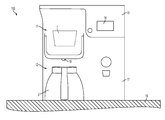
- FIG. 1 is a front view of a beverage forming apparatus with a carafe located at a carafe receiving area of a beverage forming machine according to one embodiment
- FIG. 2 is a left side view of an apparatus according to one embodiment
- FIG. 3 is a right side view of an apparatus according to one embodiment
- FIG. 4 is a perspective view of a carafe receiving area according to one embodiment
- FIG. 5 is a perspective view of a carafe according to one embodiment
- FIG. 6 is a schematic side view of a beverage forming apparatus according to one embodiment
- FIG. 7 is a bottom view of a beverage forming apparatus with a carafe located at a carafe receiving area of a beverage forming machine according to one embodiment
- FIG. 8 is a perspective view of a carafe at a carafe receiving area according to one embodiment
- FIG. 9 is the FIG. 8 embodiment with the carafe disengaged from a housing
- FIG. 10 is a schematic diagram of components of a beverage forming apparatus according to one embodiment.
- FIG. 11A is perspective view of a drip tray engaged with a housing according to one embodiment.
- FIG. 11B is the FIG. 11A embodiment with the drip tray disengaged from a housing
- FIG. 12 is perspective view of a drip tray according to one embodiment
- FIG. 13 is perspective view of a carafe receiving area according to one embodiment.
- FIG. 14 is schematic side view of a beverage forming apparatus according to one embodiment.
- FIG. 1 shows a front view of a beverage forming apparatus 100 in an illustrative embodiment that incorporates aspects of the invention.
- the beverage forming apparatus 100 may be used to form any suitable beverage, such as tea, coffee, other infusion-type beverages, beverages formed from a liquid or powdered concentrate, soups, juices or other beverages made from dried materials, or other, in this illustrative embodiment, the apparatus 100 is arranged to form coffee or tea beverages.
- a beverage cartridge 1 may be provided to the apparatus 100 and used to form a beverage that is deposited into a carafe 2 .
- a carafe includes any suitable container arranged to receive a dispensed beverage.
- the cartridge 1 may be manually or automatically placed in a beverage forming station 11 of a beverage forming machine 10 .
- the beverage forming station 11 may include a cartridge receiver that is exposed to receive the cartridge 1 when the user operates a handle or other actuator. With the cartridge 1 placed in the cartridge receiver, the actuator may be operated to at least partially enclose the cartridge 1 , e.g., so that water or another precursor liquid can be introduced into the cartridge 1 to form a beverage.
- the cartridge 1 may be pierced to form inlet and outlet openings through which water or other precursor liquid enters the cartridge 1 and beverage exits the cartridge 1 , respectively.
- U.S. Pat. No. 8,361,527 describes a cartridge and a system for introducing liquid into the cartridge that may be used in an embodiment of this invention, and is hereby incorporated by reference in its entirety.
- aspects of the invention may be employed with any suitably arranged apparatus 100 , including drip-type coffee brewers, carbonated beverage machines, and others arranged to form a beverage regardless of how the beverage is formed.
- a cartridge 1 need not be used, and instead beverage material used to form a beverage may be provided to a mixing chamber or brew basket by a user or via a hopper system.
- the beverage forming machine 10 includes a housing 17 that houses and supports components of the machine 10 , such as a user interface 14 used to control system operation, and defines a carafe receiving area 12 at which the carafe 2 is positionable to receive the beverage dispensed by the machine 10 .
- the carafe 2 is associated with the machine 10 to receive a dispensed beverage and may be supported by the housing 17 .
- the machine 10 may be placed on a surface 19 (e.g., a kitchen counter), and when the carafe 2 is placed at the carafe receiving area 12 , the carafe 2 also may be positioned on the surface 19 .
- the carafe 2 may be received at the carafe receiving area 12 so that the carafe 2 is at least partially surrounded by the housing 17 .
- the housing 17 may be configured such that the carafe 2 is more or less exposed when at the carafe receiving area 12 .
- the housing 17 is configured such that the carafe 2 is less exposed at the carafe receiving area 12 .
- the housing 17 is configured to engage with the carafe 2 .
- the housing has a first recess 32 in an exterior surface 34 of the housing 17 for engaging with the carafe 2 .
- the first recess 32 may be formed in a lower portion of the exterior surface 34 , adjacent the carafe receiving area 12 .
- first recess 32 may be located in any suitable portion of the housing 17 as this aspect of the disclosure is not limited in this regard.
- the first recess 32 may have any shape or size suitable for engaging with the carafe 2 .
- the housing has a second recess 36 for engaging with a drip tray 40 (see FIGS. 11A and 11B ).
- the second recess 36 may be formed in a lower portion of the housing 17 , although the second recess 36 also may be formed in another suitable portion of the housing for engaging with the drip tray 40 .
- the second recess 36 is formed in the exterior surface 34 of the housing 17 , adjacent the carafe receiving area 12 .
- the second recess 36 is formed above the first recess 32 . A person having ordinary skill in the art should appreciate that although the second recess 36 is shown adjacent to the first recess 32 in FIG.
- the first and second recesses 32 , 36 may be separated from one another.
- the second recess 36 may have any shape or size suitable for engagement with the drip tray.
- the shape and size of the second recess 36 may be the same as the shape and size of the first recess 32 , although the shape and size of the first and second recesses 32 , 36 also may be different.
- FIG. 5 shows a perspective view of a carafe 2 according to one embodiment.
- the carafe 2 may include a body 21 that defines an interior space that holds a beverage.
- the body 21 may be shaped, formed or otherwise constructed in any suitable way and of any suitable material or combination of materials.
- the body 21 may be formed of a molded plastic material, metal, or other, and may be insulated or not.
- the carafe has a protrusion 30 associated with the carafe 2 for engagement with the housing 17 when the carafe 2 is at the carafe receiving area 12 .
- the protrusion 30 may be associated with a bottom side portion of the carafe 2 , as is shown in FIG. 5 , although the protrusion 30 also may be associated with any suitable portion of the carafe 2 .
- the protrusion 30 may be associated with the body 21 , the handle 25 , and/or the cover 22 .
- the location of the protrusion 30 on the carafe 2 corresponds to the location of the first recess 32 on the housing, e.g., the protrusion 30 is located at a same height above a bottom of the carafe 2 as the first recess 32 is located above a bottom of the machine 10 .
- the protrusion 30 and first recess 32 may be located at a same height above the surface 19 on which the machine 10 and carafe 2 are supported.
- the first recess 32 is located at the bottom of the machine 10 and both the carafe 2 and the protrusion 30 are supported on the surface 19 .
- the carafe 2 may have more than one associated protrusion 30 .
- the housing 17 may have more than one corresponding first recess 32 to engage with the protrusions 30 .
- all the protrusions may be associated with the same portion of the carafe 2 (e.g., with the bottom side portion of the carafe), the protrusions also may be associated with different portions (e.g., with the body and with the bottom side portion).
- the protrusion 30 is removably attachable to the carafe 2 .
- the protrusion 30 may be magnetically connected to the carafe 2 .
- the protrusion 30 may be connected to the carafe 2 for engagement with the housing and then disconnected from the carafe after beverage formation (e.g., for serving the beverage).
- the protrusion 30 also may be connectable to the carafe 2 via an interface (e.g., via a harness that removably attaches to the carafe 2 ).
- the protrusion 30 is permanently attached to the carafe 2 .
- the protrusion 30 may be attached to the carafe 2 via any suitable method (e.g., via fasteners or via screws).
- the carafe 2 may be formed or otherwise constructed such that the protrusion 30 is fixed or integral with the carafe 2 .
- the protrusion 30 may be shaped, formed or otherwise constructed in any suitable way and of any suitable material.
- the protrusion 30 has a curved shape, e.g., in the form of a partial disc element.
- the protrusion also may be circular, semicircular, or any other suitable shape as this aspect of the disclosure is not limited in this regard.
- the protrusion 30 also may have a square, triangular, or rectangular shape.
- the shape of the protrusion 30 corresponds to the shape of the first recess 32 . As seen in FIG.
- the protrusion also may have any suitable size as this aspect of the disclosure is not limited in this regard.
- the protrusion 30 may have a thickness T.
- the thickness T of the protrusion is less than about 3 cm.
- Other suitable thicknesses T of the protrusion 30 may be used for engaging the carafe 2 with the housing 17 .
- the protrusion has a length L (or, for protrusions having a circular or semicircular shape, a radius R).
- the length L of the protrusion is larger than the thickness T of the protrusion.
- the size and thickness T of the protrusion corresponds to the size and thickness of the first recess 32 .
- the protrusion 30 may be configured to notify the apparatus 100 of the presence of the carafe 2 at the carafe receiving area 12 .
- the protrusion includes a magnetic element configured to alert the presence of the carafe 2 .
- the protrusion 30 includes a magnet 39 .
- the magnet 39 is embedded in the protrusion 30 , although the magnet 39 also may be attachable to an outer surface of the protrusion 30 .
- the protrusion 30 also may be formed of or coated with a magnetic material, or may be formed of steel or another suitable material that may be magnetized. A person having ordinary skill in the art should appreciate that the protrusion 30 also may be formed of other suitable materials or combination of materials or may include other components suitable for notifying the apparatus 100 of the presence of the carafe 2 at the carafe receiving area 12 .
- the apparatus 100 includes a detector 13 that is arranged to detect the presence or absence of the carafe 2 at the carafe receiving area 12 .
- the carafe 2 cannot be detected at the carafe receiving area 12 when the drip tray 40 is engaged with the housing 17 .
- the drip tray 40 blocks access to the first recess 32 (e.g., the protrusion cannot be received by the first recess 32 ).
- the detector 13 is configured to detect the presence of the magnetic element.
- the detector 13 may be located adjacent to the exterior surface of the first recess 32 .
- the detector also may be positioned inside the housing 17 , or may be embedded in the exterior surface 34 of the housing or in an exterior wall of the first recess 32 .
- FIG. 7 although the apparatus includes only one detector 13 , more than one detector 13 may be used for detecting the presence or absence of the magnetic element (and, thus, the carafe 2 at the carafe receiving area 12 ).
- the detector 13 detects the presence of the magnetic element of the protrusion 30 via a sensor.
- the detector 13 includes a reed switch, although other suitable detectors may be used as this aspect of the disclosure is not limited in this regard.
- the detector 13 includes a hall effect sensor to detect the magnetic element.
- the detector 13 also may include an inductive, resistive, capacitive, or other sensor suitable for detecting the magnetic element as this aspect of the disclosure is not limited in this regard.
- the detector 13 only detects the carafe 2 (e.g., the switch is only closed) when the protrusion 30 is fully inserted into the first recess 32 and the magnet 39 is in close proximity to the sensor 13 .
- detector 13 may have other arrangements for detecting the carafe 2 .
- the detector 13 may include a switch that is mechanically actuated when the protrusion 30 is inserted into the first recess 32 .
- the detector 13 may detect the presence of an RFID tag or another component via radio frequency energy.
- the detector 13 also may include an optical sensor.
- the carafe need not include a protrusion that is detected by the machine 10 , but rather the carafe may include a recess that receives a protrusion of the machine (see, e.g., FIG.
- the carafe may include neither a protrusion nor a recess, e.g., may include a magnetic element embedded in the body of the carafe that is detected by the detector.
- the machine need not include a protrusion or recess, but may detect the presence and/or absence of the carafe without such features.
- the apparatus 100 is configured to set the rotational position of the carafe 2 at the carafe receiving area 12 , e.g., based on engagement of the carafe with the housing 17 .
- the body 21 of the carafe 2 defines a top opening that receives a cover 22 .
- the cover 22 may be removable from the body 21 , e.g., to allow easier cleaning of the interior space, and may engage the body 21 in any suitable way.
- the cover 22 may have a cylindrical portion that fits within the top opening of the body 21 and one or more gaskets (such as an o-ring positioned on the cylindrical portion) may help provide a water-tight seal between the cover 22 and the body 21 when the cylindrical portion is fitted into the top opening.
- the cover 22 may threadedly engage with the body 21 , and may include a gasket (such as a rubber washer positioned between a rim of the body 21 at the top opening and the cover 22 ) that provides a seal when the cover 22 is tightened to the body 21 .
- the cover 22 includes a beverage opening 23 through which the beverage is dispensed into interior space of the body 21 .
- the opening 23 is a small opening, although the opening may be any size suitable for allowing a beverage to be dispensed into the interior space of the body 21 .
- the opening 23 has a size of less than about 2 cm, although the opening 23 may have other suitable sizes.
- the body has a spout 26 configured to dispense the beverage from the interior space. As shown in FIG.
- the opening 23 may be located near the spout in some embodiments, although the opening may be placed in any suitable portion of the cover 22 to allow the beverage to be dispensed into the interior space of the body 21 .
- the opening may have a lid that covers the opening 23 or is made as a plug that fits into the beverage opening and is removable from the opening 23 .
- the opening 23 is located in a portion of the cover 22 that corresponds with beverage outlet 18 of the housing 17 .
- the beverage opening 23 is positioned below the outlet 18 when the carafe 2 is at the carafe receiving area 12 and the protrusion 30 is inserted in the first recess 32 .
- precise contact geometry between the protrusion 30 and the first recess 32 aligns the opening 23 below the outlet 18 .
- engagement between the protrusion 30 and the first recess 32 sets the rotational position of the carafe 2 at the carafe receiving area 12 .
- engagement between the protrusion and the first recess may include reception of the protrusion by the first recess with or without contact between the protrusion and the first recess.
- the protrusion may be inserted into and received by the first recess without any physical interaction or contact between the protrusion and the first recess.
- the carafe 2 when the carafe 2 is disengaged from the housing 17 , the carafe 2 may rotate in any suitable direction (e.g., about an axis A).
- engagement between the protrusion 30 and the first recess 32 may limit the X and Y rotation of the carafe. This, in turn, may maintain the position of the opening 23 below the outlet 18 during beverage formation.
- FIG. 7 for example, when the protrusion 30 is received at the first recess 32 the rotational movement of the carafe at the carafe receiving area 12 is limited.
- FIG. 10 shows a schematic block diagram of various components that may be included in a beverage forming apparatus 100 in one embodiment.
- a beverage forming apparatus 100 may be configured in a variety of different ways, and thus aspects of the invention should not be narrowly interpreted as relating only to one type of beverage forming apparatus.
- Water or other precursor liquid may be provided by a liquid supply 15 to mix with a beverage material at a beverage forming station 11 .
- the beverage material (such as coffee grounds, tea leaves, a powdered drink mix, etc.) may be provided in a cartridge 1 , or not, and beverage produced by mixing the liquid with the beverage material may be dispensed into the carafe 2 .
- the liquid supply 15 in this embodiment includes a valve 151 that is coupled to a source W that provides liquid from a storage tank, a mains water supply or other source.
- the valve 151 is controlled by a control circuit 16 to open and close to provide a desired volume of liquid to a tank 152 .
- the valve 151 may be opened until a conductive probe or other water level sensor 157 provides a signal to the control circuit 16 that indicates when liquid arrives near or at a top of the tank 152 .
- the control circuit 16 may close the valve 151 .
- a pump e.g., a centrifugal pump, piston pump, solenoid pump, diaphragm pump, etc.
- Other optional features such as a vent 155 which can be opened or closed to vent the tank 152 , a check valve or other flow controller that can prevent backflow in the conduit between the source W and the tank 152 , or other features may be included.
- the vent 155 is not controlled by the control circuit 16 , but remains always open with an orifice of suitable size to allow venting for filling of the tank 152 , and pressure buildup in the tank 152 to allow liquid delivery.
- control of a volume of liquid provided to the tank 152 may be performed in other ways, such as opening the valve 151 for a defined period of time, running a pump for a predetermined time, detecting a flow rate or volume of liquid entering the tank 152 (e.g., using a flow meter), operating a pump for a desired number of cycles (such as where the pump is arranged to deliver a known volume of liquid for each cycle), detecting a pressure rise in the tank 152 using a pressure sensor, or using any other viable technique.
- Liquid in the tank 152 may be heated by way of a heating element 153 whose operation is controlled by the control circuit 16 using input from a temperature sensor or other suitable input.
- heating of the liquid is not necessary, and instead (or additionally) the apparatus 100 may include a chiller to cool the liquid, a carbonator to carbonate the liquid, or other system to otherwise condition the liquid.
- liquid in the tank 152 may be dispensed via a conduit 156 to the beverage forming station 11 .
- the liquid may be discharged from the tank 152 by an air pump 154 operating to force air into the tank 152 to pressurize the tank and force liquid to flow in the conduit 156 to the beverage forming station 11 .
- liquid may be caused to flow from the tank 152 to the beverage forming station 11 in other ways, such as by opening the valve 151 to force additional unheated liquid into the tank 152 , thereby displacing water out of the tank 152 and into the conduit 156 .
- a flow sensor or other suitable device may be used to determine the amount of liquid delivered to the tank 152 , and thus the amount of liquid delivered to the beverage forming station 11 .
- a pump may be used to force additional liquid into the tank 152 , or to pump liquid from the tank 152 to the forming station 11 .
- a specified volume of liquid may be delivered to the forming station 152 by operating a pump to deliver the specified volume of liquid from the source W to the tank 152 , e.g., a diaphragm pump may deliver 5 ml for each pump stroke, and thus 100 ml of liquid may be delivered to the tank 152 by operating the pump through 20 pump cycles.
- Liquid may be introduced to the beverage forming station 11 at any suitable pressure, e.g., 1-2 psi, 30-50 psi, or higher.
- the conduit 156 is shown as extending into the tank 152 , the conduit 156 could be arranged in other suitable ways.
- the outlet of the heater tank 152 to the conduit 156 could be arranged at an extreme top of the tank 152 , or in other ways.
- the conduit 156 may include a check valve or other flow controller, e.g., to help prevent backflow in the tank conduit 156 from the forming station 11 .
- the beverage forming station 11 may use any beverage making ingredient, such as ground coffee, tea, a flavored drink mix, or other beverage medium, e.g., contained in a cartridge 1 or not. Alternately, the beverage forming station 11 may function simply as an outlet for heated, cooled or otherwise conditioned water or other liquid, e.g., where a beverage medium is contained in the carafe 2 .
- the air pump 154 (or other air pump) may be operated to force air into the conduit 156 to purge liquid from the beverage forming station 11 , at least to some extent.
- Operation of the valve 151 , air pump 154 and other components of the apparatus 100 may be controlled by the control circuit 16 , e.g., which may include a programmed processor and/or other data processing device along with suitable software or other operating instructions, one or more memories (including non-transient storage media that may store software and/or other operating instructions), temperature and liquid level sensors, pressure sensors, input/output interfaces, communication buses or other links, a display, switches, relays, triacs, or other components necessary to perform desired input/output or other functions.
- the control circuit 16 e.g., which may include a programmed processor and/or other data processing device along with suitable software or other operating instructions, one or more memories (including non-transient storage media that may store software and/or other operating instructions), temperature and liquid level sensors, pressure sensors, input/output interfaces, communication buses or other links, a display, switches, relays, triacs, or other components necessary to perform desired input/output or other functions.
- the beverage forming apparatus 100 may include a detector 13 that detects whether the carafe 2 is at the carafe receiving area 12 by detecting the presence or absence of the magnetic element when the protrusion is received by the first recess 32 .
- the control circuit 16 may control the apparatus 100 to dispense the stored beverage from the holding tank to the carafe 2 in an amount greater than a threshold volume V T .
- the threshold volume V T is about 8 to 20 ounces and the apparatus 100 is configured to dispense 24 or 32 ounces of beverage, for example, only when the carafe is detected.
- control circuit 16 may prevent the apparatus from dispensing any additional beverage.
- the apparatus 100 also may be configured to resume dispensing the beverage if the carafe 2 is thereafter returned to the carafe receiving area 12 (e.g., the magnetic element is redetected).
- control circuit 24 may be configured such that the apparatus may dispense only a volume less than the threshold volume V T when the magnetic element is not detected (e.g., when the drip tray 40 is engaged with the housing 17 ).
- a container smaller than the carafe 2 may be associated with the housing 17 , e.g., positioned at the carafe receiving area 12 and placed on the drip tray 40 , to receive a volume of beverage less than the threshold volume V T .
- the carafe 2 may be positionable at the carafe receiving area 12 and placed on the drip tray (e.g., the protrusion 30 is not received in the first recess 32 ) to receive a volume of beverage less than the threshold volume V T .
- the apparatus 100 dispenses a volume less than about 8 to 20 ounces when the detector 13 detects the absence of the magnetic element (e.g., 8, 12, or 16 ounces of the beverage is dispensable).
- the detector 13 may include one or more sensors (e.g., a reed switch, a hall effect switch, or another suitable switch) which are closed by reception of the protrusion 30 into the first recess 32 .
- the control circuitry 16 may be arranged to suitably interpret any type of signal provided by the detector 13 to determine the presence or absence of the magnetic element and, thus, the carafe 2 .
- the apparatus has a drip tray 40 for collecting excess or spilled beverage.
- the drip tray may have any suitable shape and may be formed of any suitable material as this aspect of the disclosure is not limited in this regard. Similar to the carafe 2 , the drip tray 40 also may be placed on the same surface 19 that supports the machine 10 (see e.g., FIGS. 11A and 11B , which are perspective views of the carafe receiving area with the drip tray engaged and disengaged, respectively).
- the drip tray 40 may have at least one engagement feature, such as a tab 42 , for engaging the drip tray 40 with the housing 17 .
- the drip tray 40 also may engage with the second recess 36 via other suitable engagement features, e.g., hooks, threads, notches, or latches.
- the engagement feature(s) may be permanently attached to the drip tray 40 in one embodiment, while in other embodiments the engagement feature(s) may be removably attachable to the drip tray 40 .
- the engagement feature(s) may be attached to the drip tray 40 via any suitable method.
- the engagement feature(s) also may be shaped, formed or otherwise constructed in any suitable way and of any suitable material.
- the engagement feature(s) also may have any suitable size.
- the shape and size of the engagement feature(s) may correspond to the shape and size of the second recess 36 .
- the drip tray need not include engagement features for engaging the drip tray but rather the drip tray may include a recess that is engaged with engagement features on the housing.
- the at least one engagement feature engages with the second recess 36 of the housing 17 .
- the drip tray 40 cannot be engaged with the housing 17 when the carafe 2 is at the carafe receiving area 12 (e.g., the carafe 2 blocks access to the second recess 36 and prevents engagement between the engagement feature(s) and the second recess 36 ).
- the drip tray 40 may have more than one tab 42 for engaging with the second recess 36 .
- the drip tray 40 has multiple tabs 42 that are connected to one another.
- the position of the tab(s) or other engagement feature on the drip tray 40 correspond to the position of the second recess 36 or other complementary engagement feature on the housing 17 .
- the tab(s) 42 may be located at a same height above a bottom of the drip tray 40 as the second recess 36 is located above the bottom of the machine 10 .
- the tab(s) 42 and the second recess 36 may be located at a same height above the surface 19 on which the machine 10 and drip tray 40 are supported.
- the tab(s) 42 on the drip tray 40 may be the same or a different shape than the protrusion 30 associated with the carafe 2 . As shown in FIG. 13 , in some embodiments, the location in which the protrusion 30 is received by the housing 17 (e.g., the first recess 32 ) is below the location in which the at least one tab 42 engages with the housing 17 (e.g., the second recess 36 ). The tab(s) 42 also may engage with the housing to the left, right, or below the location in which the protrusion 30 is received by the housing 17 , as this aspect of the disclosure is not limited in this regard.
- the drip tray 40 is only attachable to the housing when the carafe 2 is not present (e.g., when the carafe 2 is disengaged from the housing).
- the carafe may be engaged with the housing (e.g., the protrusion 30 may be received by the first recess 32 ) only when the drip tray 40 is disengaged from the housing 17 .
- the carafe 2 also may be positionable at the receiving area via placement of the carafe 2 on the drip tray 40 .
- the carafe 2 is not engaged with the housing 17 (e.g., the protrusion 30 is not received by the first recess 32 ), but the carafe 2 is still positioned to receive the beverage (e.g., in a volume less than the threshold volume V T ).
- the drip tray 40 is not configured to notify the apparatus 100 or otherwise be detected by the machine 10 when the drip tray 40 is engaged with the housing 17 .
- the apparatus 100 may be configured with a second detector (not shown) to detect the presence of the drip tray 40 , or the detector 13 may detect the presence of the drip tray as well as the carafe.
- the at least one tab 42 may comprise a magnetic element (similar to the protrusion 30 ) that is detected by at least one detector (e.g., a reed switch, a hall effect switch, or another suitable switch).
- a method for controlling a beverage forming apparatus may include placing a carafe at a carafe receiving area of a beverage forming machine where the carafe has a body defining an interior space for holding a beverage, an opening through which beverage is dispensable into the interior space, and a protrusion associated with a lower side portion of the carafe.
- the apparatus includes a housing with a first recess and the protrusion of the carafe has a magnetic element.
- the carafe may be placed at the carafe receiving area such that the protrusion is inserted into the first recess.
- the opening is positioned below an outlet for dispensing the beverage from the housing.
- the detector(s) may detect the presence or absence of the magnetic element (and, thus, the presence of the carafe at the carafe receiving area). If the magnetic element is not detected by the detectors, only operation of the beverage forming apparatus to dispense a volume of beverage less a threshold volume V T is enabled. In some embodiments, absence of the magnetic element enables only dispensing of a volume of less than about 8 to 20 ounces (e.g., 6, 8, 12, or 16 ounces of beverage). If the magnetic element is detected by the detectors, operation of the beverage forming apparatus to dispense a volume of beverage above the threshold volume V T is enabled.
- detection of the magnetic element allows dispensing of a volume of beverage greater than about 8 to 20 ounces (e.g., 24 or 32 ounces of beverage).
- operation of the beverage forming apparatus to dispense a beverage may be paused or stopped.
- returning the carafe 2 to the beverage receiving area 2 e.g., redetecting the magnetic element
- the protrusion may be associated with the housing and the corresponding recess may be formed in the carafe.
- the carafe 2 may have a recess 44 , which, as is shown, may be formed in a lower side portion of the carafe 2 , although the recess 44 may be formed in another suitable portion of the carafe 2 for receiving a protrusion 46 .
- the protrusion 46 may be associated with a lower portion of the housing 17 , or any other suitable portion of the housing 17 .
- the location of the protrusion 46 on the housing 17 corresponds to the location of the recess 44 in the carafe 2 .
- the protrusion 46 and the recess 44 may have any suitable shape and size, and, in at least some embodiments, the shape and size of the protrusion 46 may correspond to the shape and size of the recess 44 .
- the machine 10 may have at least one detector 13 for detecting the presence of the carafe.
- the detector 13 may be located in the protrusion 46 , although the detector 13 also may be located in another portion of the housing 17 suitable for detecting the presence of the carafe 2 (e.g., in an exterior surface of the housing adjacent to the protrusion 46 ).
- the detector 13 may detect the presence of a magnetic element in the carafe 2 .
- the carafe 2 may include a magnet 39 located adjacent to the recess 44 .
- the magnet 39 is shown behind the recess 44 (adjacent to an interior surface of the recess 44 ), the magnet 39 also may be placed above or below the recess 44 .
- the magnet 39 also may be located adjacent to an exterior surface of the carafe 2 .
- other magnetic elements may be used (e.g., all or a portion of the interior surface of the recess 44 may be formed of a magnetic material).
- the detector 13 may only detect the carafe 2 (e.g., the switch is only closed) when the protrusion 46 is fully inserted into the recess 44 and the magnet 39 is in close proximity to the detector 13 .
- insertion of the protrusion 46 into the recess 44 may set the rotational position of the carafe 2 at the carafe receiving area 12 .
- the machine 10 when the detector 13 detects the presence of the magnetic element, the machine 10 is configured to dispense the stored beverage from the holding tank to the carafe in an amount greater than the threshold volume V T .
- the beverage forming apparatus 100 may use the cartridge 1 to form a beverage.
- one or more inlet needles may pierce the cartridge 1 (e.g., a lid of the cartridge) so as to inject heated water or other liquid into the cartridge 1 .
- the injected liquid may form the desired beverage or a beverage precursor by mixing with beverage medium in the cartridge 1 .
- the apparatus 100 may also include one or more outlet needles or other elements to puncture or pierce the cartridge 1 at an outlet side (e.g., at the lid of the cartridge) to permit the formed beverage to exit the cartridge 1 .
- inlet/outlet piercing arrangements are possible, such as multiple needles, a shower head, a non-hollow needle, a cone, a pyramid, a knife, a blade, etc.
- Other arrangements for an inlet or outlet are possible however, e.g., the cartridge may have a permeable portion that allows water to flow into and/or beverage to exit cartridge 1 .
- the cartridge 1 may take any suitable form such as those commonly known as a sachet, pod, capsule, container or other.
- the cartridge 1 may include an impermeable outer covering within which is housed a beverage medium, such as roasted and ground coffee or other.
- the cartridge 1 may also include a filter so that a beverage formed by interaction of the liquid with the beverage medium passes through the filter before being dispensed into a carafe 2 .
- cartridges in the form of a pod may use the outer portion of the cartridge 1 to filter the beverage formed.
- the cartridge 1 in this example may be used in a beverage machine to form any suitable beverage such as tea, coffee, other infusion-type beverages, beverages formed from a liquid or powdered concentrate, etc.
- the cartridge 1 may contain any suitable beverage medium, e.g., ground coffee, tea leaves, dry herbal tea, powdered beverage concentrate, dried fruit extract or powder, powdered or liquid concentrated bouillon or other soup, powdered or liquid medicinal materials (such as powdered vitamins, drugs or other pharmaceuticals, nutriaceuticals, etc.), and/or other beverage-making material (such as powdered milk or other creamers, sweeteners, thickeners, flavorings, and so on).
- the cartridge 1 contains a beverage medium that is configured for use with a machine that forms coffee and/or tea beverages, however, aspects of the invention are not limited in this respect.
- the apparatus may be configured to receive cartridges of different sizes and/or cartridges having different amounts beverage medium to dispense different volumes of beverages to the carafe.
- the cartridge may be suitable for forming and dispensing more than about 20 ounces of beverage while in other embodiments the cartridge may be suitable for forming less than about 20 ounces of beverage. While two ranges of beverage volumes have been noted in these example, it should be appreciated that the cartridge may be configured and sized to dispense more or less volume of beverage as this aspect of the disclosure is not limited in this regard.
- beverage refers to a liquid substance intended for drinking that is formed when a liquid interacts with a beverage medium.
- beverage refers to a liquid that is ready for consumption, e.g., is dispensed into a cup and ready for drinking, as well as a liquid that will undergo other processes or treatments, such as filtering or the addition of flavorings, creamer, sweeteners, another beverage, etc., before being consumed.
Abstract
Description
Claims (31)
Priority Applications (9)
| Application Number | Priority Date | Filing Date | Title |
|---|---|---|---|
| US14/158,191 US9173519B2 (en) | 2014-01-17 | 2014-01-17 | Method and apparatus for beverage carafe detection |
| AU2015206490A AU2015206490A1 (en) | 2014-01-17 | 2015-01-15 | Method and apparatus for beverage carafe detection |
| MYPI2016702418A MY178887A (en) | 2014-01-17 | 2015-01-15 | Method and apparatus for beverage carafe detection |
| CA2934909A CA2934909C (en) | 2014-01-17 | 2015-01-15 | Method and apparatus for beverage carafe detection |
| PCT/US2015/011524 WO2015109050A1 (en) | 2014-01-17 | 2015-01-15 | Method and apparatus for beverage carafe detection |
| KR1020167021955A KR20160107300A (en) | 2014-01-17 | 2015-01-15 | Method and apparatus for beverage carafe detection |
| EP15702327.6A EP3094591B1 (en) | 2014-01-17 | 2015-01-15 | Method and apparatus for beverage carafe detection |
| JP2016546771A JP6557665B2 (en) | 2014-01-17 | 2015-01-15 | Beverage making equipment |
| CN201580004745.8A CN105916799B (en) | 2014-01-17 | 2015-01-15 | The method and apparatus detected for beverage bottle |
Applications Claiming Priority (1)
| Application Number | Priority Date | Filing Date | Title |
|---|---|---|---|
| US14/158,191 US9173519B2 (en) | 2014-01-17 | 2014-01-17 | Method and apparatus for beverage carafe detection |
Publications (2)
| Publication Number | Publication Date |
|---|---|
| US20150201795A1 US20150201795A1 (en) | 2015-07-23 |
| US9173519B2 true US9173519B2 (en) | 2015-11-03 |
Family
ID=52444641
Family Applications (1)
| Application Number | Title | Priority Date | Filing Date |
|---|---|---|---|
| US14/158,191 Active 2034-05-01 US9173519B2 (en) | 2014-01-17 | 2014-01-17 | Method and apparatus for beverage carafe detection |
Country Status (9)
| Country | Link |
|---|---|
| US (1) | US9173519B2 (en) |
| EP (1) | EP3094591B1 (en) |
| JP (1) | JP6557665B2 (en) |
| KR (1) | KR20160107300A (en) |
| CN (1) | CN105916799B (en) |
| AU (1) | AU2015206490A1 (en) |
| CA (1) | CA2934909C (en) |
| MY (1) | MY178887A (en) |
| WO (1) | WO2015109050A1 (en) |
Cited By (1)
| Publication number | Priority date | Publication date | Assignee | Title |
|---|---|---|---|---|
| US11667508B2 (en) | 2021-08-27 | 2023-06-06 | Haier Us Appliance Solutions, Inc. | Beverage dispenser with drip tray detection |
Families Citing this family (7)
| Publication number | Priority date | Publication date | Assignee | Title |
|---|---|---|---|---|
| US20150327718A1 (en) | 2014-02-14 | 2015-11-19 | Remington Designs, Llc | Apparatuses and methods for solute extraction |
| EP3267857B1 (en) * | 2015-03-12 | 2019-01-23 | BSH Hausgeräte GmbH | Mixed beverage unit |
| WO2018119162A1 (en) * | 2016-12-20 | 2018-06-28 | TEAnGO Technologies, Inc. | Portable beverage brewing and beverage analyte tracking devices and systems |
| US11553812B2 (en) | 2019-03-11 | 2023-01-17 | B/E Aerospace, Inc. | Brewing apparatus |
| WO2020194357A1 (en) * | 2019-03-26 | 2020-10-01 | De' Longhi Appliances S.R.L. Con Unico Socio | Machine and method for preparing beverages |
| US11312611B2 (en) * | 2019-05-13 | 2022-04-26 | Lg Electronics Inc. | Hydrogen water generator |
| US11698285B2 (en) * | 2020-01-02 | 2023-07-11 | Kyndryl, Inc. | Monitoring dispensation of a substance |
Citations (74)
| Publication number | Priority date | Publication date | Assignee | Title |
|---|---|---|---|---|
| US2445591A (en) | 1946-03-09 | 1948-07-20 | Gen Electric | Coffee maker |
| US2667566A (en) | 1953-03-09 | 1954-01-26 | Knapp Monarch Co | Lower bowl construction for vacuum type coffee makers and switch therefor |
| US3291034A (en) | 1963-12-12 | 1966-12-13 | Arvin Ind Inc | Beverage dispenser |
| US4202387A (en) | 1977-08-10 | 1980-05-13 | Upton Douglas J | Fluid dispensing control system |
| DE3736517C1 (en) | 1987-10-28 | 1988-11-03 | Herbert Beesten | Coffee machine |
| US4833978A (en) | 1988-07-06 | 1989-05-30 | Black & Decker, Inc. | Intelligent coffee brewing system |
| US4997015A (en) | 1988-10-17 | 1991-03-05 | Black & Decker, Inc. | Brew through lid for coffee maker |
| DE4103820A1 (en) | 1990-04-23 | 1991-10-24 | Helbling | COFFEE MACHINE WITH PRODUCT SELECTION |
| US5158793A (en) | 1988-07-12 | 1992-10-27 | Edward Helbling | Coffee machine with product selectivity |
| US5183998A (en) | 1990-05-30 | 1993-02-02 | Mr. Coffee Inc. | Apparatus and method for heating water for infusion and the like |
| US5287795A (en) | 1991-12-11 | 1994-02-22 | Kazuo Enomoto | Coffee maker |
| US5404794A (en) | 1993-04-22 | 1995-04-11 | Cafe 98 Industries Ltd. | Coffee-making machine |
| US5503060A (en) | 1995-01-17 | 1996-04-02 | Hamilton Beach/Proctor-Silex, Inc. | Automatic drip coffeemaker and thermal carafe assembly |
| JP2679364B2 (en) | 1989-08-05 | 1997-11-19 | 富士電機株式会社 | Controller for cup-type vending machine |
| US5718163A (en) | 1995-10-05 | 1998-02-17 | Il Caffe' Del Professore S.R.L. | Electronic apparatus for coffee grinding and metering control |
| US5718162A (en) | 1996-10-10 | 1998-02-17 | Hoover; Allen E. | Brewing apparatus |
| US5782163A (en) | 1996-12-26 | 1998-07-21 | Chang; Kwei-Tang | Coffee maker |
| US5980965A (en) | 1995-07-20 | 1999-11-09 | Jefferson, Jr.; Harry D. | Coffee brewing method |
| JP2000033045A (en) | 1998-07-17 | 2000-02-02 | Nippon Dennetsu Co Ltd | Drip coffee maker |
| US6047630A (en) | 1998-02-16 | 2000-04-11 | Be Aerospace, Inc. | Beverage brewing device having an integral beverage server locking apparatus |
| US6070771A (en) | 1997-04-18 | 2000-06-06 | Bunn-O-Matic Corporation | Beverage server |
| US6227101B1 (en) | 1999-12-10 | 2001-05-08 | Masoud Rabadi | Coffeemaker with automated interlocks |
| US6279459B1 (en) | 1998-12-04 | 2001-08-28 | Amway Corporation | Coffee maker |
| US6393966B1 (en) | 1997-04-18 | 2002-05-28 | Bunn-O-Matic Corporation | Beverage server |
| US6401729B1 (en) | 2000-08-21 | 2002-06-11 | Bunn-O-Matic Corporation | Beverage reservoir cleaning apparatus and method of use |
| US6504481B2 (en) | 1999-12-10 | 2003-01-07 | David M. Teller | Service transaction monitoring system, method, and device |
| US20030051767A1 (en) * | 2001-09-19 | 2003-03-20 | Unilever Home And Personal Care Usa | Package and system |
| US20030071806A1 (en) | 2001-07-17 | 2003-04-17 | Annand Charles A. | Predetermined ordering system |
| US6705208B2 (en) | 2001-04-18 | 2004-03-16 | Food Equipment Technologies Company, Inc. | Beverage brewer with automatic safety brew basket lock and method |
| WO2004024615A1 (en) | 2002-08-28 | 2004-03-25 | Niro-Plan Ag | Dispensing device for drinks |
| CN2636781Y (en) | 2003-06-05 | 2004-09-01 | 韦坤莲 | Container material quality detecting sensor for coffee maker |
| CN2692634Y (en) | 2004-03-29 | 2005-04-13 | 深圳市信威电子有限公司 | Approach sensor |
| WO2005048794A1 (en) | 2003-11-24 | 2005-06-02 | Eurogalley Aircraft Interiors, S.L. | Coffee maker for aircraft |
| US20050247206A1 (en) | 2004-05-06 | 2005-11-10 | Wilbur Curtis Company (Ca Corporation) | Proximity link controller for equipment and product |
| US6971546B2 (en) | 2002-02-01 | 2005-12-06 | Marc Robert Costa | Dispenser of single-use portions of preparations for beverages, particularly coffee or the like |
| US7024983B2 (en) | 2003-10-10 | 2006-04-11 | Hp Intellectual Corp. | Brewing apparatus hot water control |
| US20060144244A1 (en) | 2004-02-13 | 2006-07-06 | Intelligent Coffee Company, Llc | Liquid concentrate/extract beverage dispenser with replaceable concentrate/extract cartridge |
| DE202006012326U1 (en) | 2006-08-10 | 2006-12-14 | Luxoplast Kunststofftechnik Gmbh | Coffee or tea machine has a water heater which only operates when its tap is opened, water being pumped from tank into heater |
| WO2007023117A1 (en) | 2005-08-26 | 2007-03-01 | BSH Bosch und Siemens Hausgeräte GmbH | Kitchen appliance comprising a magnetic safety lock system |
| WO2007023116A1 (en) | 2005-08-26 | 2007-03-01 | BSH Bosch und Siemens Hausgeräte GmbH | Kitchen appliance comprising a magnetic safety lock |
| US7223427B2 (en) | 1999-06-21 | 2007-05-29 | Bunn-O-Matic Corporation | Beverage maker interface |
| US20070169633A1 (en) | 2005-08-09 | 2007-07-26 | Beesley Brian K | Method for making and selectively dispensing a beverage |
| US20080041233A1 (en) | 2002-07-16 | 2008-02-21 | Bunn Arthur H | Temperature Control System |
| CN201026129Y (en) | 2007-02-06 | 2008-02-27 | 红精灵设计有限公司 | Improved coffee pot |
| US20080148954A1 (en) | 2006-12-22 | 2008-06-26 | Maldanis Algert J | Safety brewer |
| US20080223217A1 (en) | 2005-09-29 | 2008-09-18 | Carrier Commercial Refrigeration, Inc. | Brewing System and Methods |
| US7439859B2 (en) | 2003-10-23 | 2008-10-21 | Whirley Industries, Inc. | RF device in drinkware to record data/initiate sequence of behavior |
| US20080314255A1 (en) | 2007-06-21 | 2008-12-25 | Wen-Ching Lee | Coffee or tea maker |
| DE202008015525U1 (en) | 2008-11-22 | 2009-02-19 | SEVERIN ELEKTROGERÄTE GmbH | Electric household appliance |
| US7503253B2 (en) | 2004-02-09 | 2009-03-17 | Bunn-O-Matic Corporation | Apparatus, system and method for infusing a pre-packaged pod |
| US7533602B2 (en) | 2004-03-03 | 2009-05-19 | Sanyo Electric Co., Ltd. | Beverage manufacturing apparatus |
| WO2009111742A2 (en) | 2008-03-06 | 2009-09-11 | Bunn-O-Matic Corporation | Brewer system including pervasive rfid sensing for servers |
| US20100011964A1 (en) | 2007-02-13 | 2010-01-21 | Breville Pty Limited | Coffee Maker with Single Serve Setting |
| US20100018403A1 (en) | 2006-10-24 | 2010-01-28 | Breville Pty Limited | Tea Maker |
| US7673555B2 (en) | 2005-04-11 | 2010-03-09 | Starbucks Corporation | Machine for brewing a beverage such as coffee and related method |
| US7673556B2 (en) | 2004-07-19 | 2010-03-09 | Spencer William L | Coffee maker and method of use |
| US20100083841A1 (en) | 2006-10-24 | 2010-04-08 | Infusion Integrale Inc. | Beverage dispensing apparatus |
| US7698992B2 (en) | 2003-06-05 | 2010-04-20 | Toptechnology Co., Ltd. | Multi-function coffee maker |
| US7768396B2 (en) | 1999-12-10 | 2010-08-03 | Beverage Metrics Holding Ltd | Monitoring beverage dispensing using pour event data and ring up data |
| US20100200110A1 (en) | 2009-02-11 | 2010-08-12 | Pepsico, Inc. | Beverage Dispense Valve Controlled by Wireless Technology |
| DE102010023668A1 (en) | 2010-06-12 | 2010-12-23 | SEVERIN ELEKTROGERÄTE GmbH | Coffee machine, has detection mechanism with detection units arranged at machine and fixed at housing, and sensor part held at container by floating body and communicated with detection units |
| WO2011012513A1 (en) | 2009-07-31 | 2011-02-03 | Wmf Württembergische Metallwarenfabrik Ag | Coffee machine comprising a sensor unit |
| US7891287B2 (en) | 2004-06-16 | 2011-02-22 | Mag Aerospace Industries, Inc. | Coffee maker suitable for aircraft use |
| US20110100228A1 (en) | 2009-10-30 | 2011-05-05 | Adrian Rivera | Coffee Maker With Multi and Single Cup Modes |
| US7950578B2 (en) | 2004-08-10 | 2011-05-31 | Tuttoespresso S.R.L. | Apparatus and method for dispensing machine control |
| US20110185907A1 (en) | 2009-01-13 | 2011-08-04 | De'longhi S.P.A. | Apparatus for producing a coffee beverage and method of filling the receptacle of said apparatus |
| US8056468B2 (en) | 2006-07-14 | 2011-11-15 | De'longhi S.P.A. | Apparatus for producing a coffee beverage and method of filling the receptacle of said apparatus |
| US20110315020A1 (en) | 2010-06-29 | 2011-12-29 | Eugster/Frismag Ag | Automated Coffee Machine Including a Position Detection Device and/or Positioning Speed Detection Device |
| WO2012097403A1 (en) | 2011-01-19 | 2012-07-26 | NKOTB Pty Ltd | Formula dispensing unit |
| US20130118639A1 (en) | 2008-05-20 | 2013-05-16 | Grinon Industries | Fluid transfer assembly and methods of fluid transfer |
| US20130160653A1 (en) | 2011-12-27 | 2013-06-27 | Whirlpool Corporation | Coffee maker with drip stop supporting single serve & carafe operation |
| US20130164422A1 (en) * | 2011-12-27 | 2013-06-27 | Whirlpool Corporation | Coffee maker supporting single serve & carafe operation |
| US8516948B2 (en) | 2006-09-07 | 2013-08-27 | Keurig, Incorporated | Method and apparatus for beverage formation with pneumatically sealed reservoir |
| US8534187B2 (en) | 1997-04-18 | 2013-09-17 | Bunn-O-Matic Corporation | Beverage server |
Family Cites Families (3)
| Publication number | Priority date | Publication date | Assignee | Title |
|---|---|---|---|---|
| JP2001070163A (en) * | 1999-09-03 | 2001-03-21 | Matsushita Electric Ind Co Ltd | Beverage extraction machine |
| WO2007021691A1 (en) * | 2005-08-09 | 2007-02-22 | Back To Basics Products, Llc. | Coffee maker with dual use pour and dispensing carafe and method |
| US8361527B2 (en) | 2010-09-02 | 2013-01-29 | Keurig, Incorporated | Beverage cartridge |
-
2014
- 2014-01-17 US US14/158,191 patent/US9173519B2/en active Active
-
2015
- 2015-01-15 EP EP15702327.6A patent/EP3094591B1/en active Active
- 2015-01-15 MY MYPI2016702418A patent/MY178887A/en unknown
- 2015-01-15 CA CA2934909A patent/CA2934909C/en active Active
- 2015-01-15 WO PCT/US2015/011524 patent/WO2015109050A1/en active Application Filing
- 2015-01-15 AU AU2015206490A patent/AU2015206490A1/en not_active Abandoned
- 2015-01-15 JP JP2016546771A patent/JP6557665B2/en active Active
- 2015-01-15 CN CN201580004745.8A patent/CN105916799B/en active Active
- 2015-01-15 KR KR1020167021955A patent/KR20160107300A/en active IP Right Grant
Patent Citations (79)
| Publication number | Priority date | Publication date | Assignee | Title |
|---|---|---|---|---|
| US2445591A (en) | 1946-03-09 | 1948-07-20 | Gen Electric | Coffee maker |
| US2667566A (en) | 1953-03-09 | 1954-01-26 | Knapp Monarch Co | Lower bowl construction for vacuum type coffee makers and switch therefor |
| US3291034A (en) | 1963-12-12 | 1966-12-13 | Arvin Ind Inc | Beverage dispenser |
| US4202387A (en) | 1977-08-10 | 1980-05-13 | Upton Douglas J | Fluid dispensing control system |
| DE3736517C1 (en) | 1987-10-28 | 1988-11-03 | Herbert Beesten | Coffee machine |
| US4833978A (en) | 1988-07-06 | 1989-05-30 | Black & Decker, Inc. | Intelligent coffee brewing system |
| US5158793A (en) | 1988-07-12 | 1992-10-27 | Edward Helbling | Coffee machine with product selectivity |
| US4997015A (en) | 1988-10-17 | 1991-03-05 | Black & Decker, Inc. | Brew through lid for coffee maker |
| JP2679364B2 (en) | 1989-08-05 | 1997-11-19 | 富士電機株式会社 | Controller for cup-type vending machine |
| DE4103820A1 (en) | 1990-04-23 | 1991-10-24 | Helbling | COFFEE MACHINE WITH PRODUCT SELECTION |
| US5094153A (en) | 1990-04-23 | 1992-03-10 | Edward Helbling | Coffee machine with product selectivity |
| US5183998A (en) | 1990-05-30 | 1993-02-02 | Mr. Coffee Inc. | Apparatus and method for heating water for infusion and the like |
| US5287795A (en) | 1991-12-11 | 1994-02-22 | Kazuo Enomoto | Coffee maker |
| US5404794A (en) | 1993-04-22 | 1995-04-11 | Cafe 98 Industries Ltd. | Coffee-making machine |
| US5503060A (en) | 1995-01-17 | 1996-04-02 | Hamilton Beach/Proctor-Silex, Inc. | Automatic drip coffeemaker and thermal carafe assembly |
| US5980965A (en) | 1995-07-20 | 1999-11-09 | Jefferson, Jr.; Harry D. | Coffee brewing method |
| US5718163A (en) | 1995-10-05 | 1998-02-17 | Il Caffe' Del Professore S.R.L. | Electronic apparatus for coffee grinding and metering control |
| US5718162A (en) | 1996-10-10 | 1998-02-17 | Hoover; Allen E. | Brewing apparatus |
| US5782163A (en) | 1996-12-26 | 1998-07-21 | Chang; Kwei-Tang | Coffee maker |
| US6089409A (en) | 1997-04-18 | 2000-07-18 | Bunn-O-Matic Corporation | Beverage server |
| US8534187B2 (en) | 1997-04-18 | 2013-09-17 | Bunn-O-Matic Corporation | Beverage server |
| US6393966B1 (en) | 1997-04-18 | 2002-05-28 | Bunn-O-Matic Corporation | Beverage server |
| US6070771A (en) | 1997-04-18 | 2000-06-06 | Bunn-O-Matic Corporation | Beverage server |
| US6047630A (en) | 1998-02-16 | 2000-04-11 | Be Aerospace, Inc. | Beverage brewing device having an integral beverage server locking apparatus |
| US6050175A (en) | 1998-02-16 | 2000-04-18 | Be Aerospace, Inc. | Beverage brewing device having an integral beverage server locking apparatus |
| JP2000033045A (en) | 1998-07-17 | 2000-02-02 | Nippon Dennetsu Co Ltd | Drip coffee maker |
| US6279459B1 (en) | 1998-12-04 | 2001-08-28 | Amway Corporation | Coffee maker |
| US7223427B2 (en) | 1999-06-21 | 2007-05-29 | Bunn-O-Matic Corporation | Beverage maker interface |
| US6504481B2 (en) | 1999-12-10 | 2003-01-07 | David M. Teller | Service transaction monitoring system, method, and device |
| US7768396B2 (en) | 1999-12-10 | 2010-08-03 | Beverage Metrics Holding Ltd | Monitoring beverage dispensing using pour event data and ring up data |
| US6227101B1 (en) | 1999-12-10 | 2001-05-08 | Masoud Rabadi | Coffeemaker with automated interlocks |
| US6401729B1 (en) | 2000-08-21 | 2002-06-11 | Bunn-O-Matic Corporation | Beverage reservoir cleaning apparatus and method of use |
| US6705208B2 (en) | 2001-04-18 | 2004-03-16 | Food Equipment Technologies Company, Inc. | Beverage brewer with automatic safety brew basket lock and method |
| US20030071806A1 (en) | 2001-07-17 | 2003-04-17 | Annand Charles A. | Predetermined ordering system |
| US20030051767A1 (en) * | 2001-09-19 | 2003-03-20 | Unilever Home And Personal Care Usa | Package and system |
| US6971546B2 (en) | 2002-02-01 | 2005-12-06 | Marc Robert Costa | Dispenser of single-use portions of preparations for beverages, particularly coffee or the like |
| US20080041233A1 (en) | 2002-07-16 | 2008-02-21 | Bunn Arthur H | Temperature Control System |
| WO2004024615A1 (en) | 2002-08-28 | 2004-03-25 | Niro-Plan Ag | Dispensing device for drinks |
| US7637205B2 (en) | 2002-08-28 | 2009-12-29 | Niro-Plan Ag | Dispensing device for drinks |
| US7698992B2 (en) | 2003-06-05 | 2010-04-20 | Toptechnology Co., Ltd. | Multi-function coffee maker |
| CN2636781Y (en) | 2003-06-05 | 2004-09-01 | 韦坤莲 | Container material quality detecting sensor for coffee maker |
| US7024983B2 (en) | 2003-10-10 | 2006-04-11 | Hp Intellectual Corp. | Brewing apparatus hot water control |
| US7439859B2 (en) | 2003-10-23 | 2008-10-21 | Whirley Industries, Inc. | RF device in drinkware to record data/initiate sequence of behavior |
| WO2005048794A1 (en) | 2003-11-24 | 2005-06-02 | Eurogalley Aircraft Interiors, S.L. | Coffee maker for aircraft |
| US7503253B2 (en) | 2004-02-09 | 2009-03-17 | Bunn-O-Matic Corporation | Apparatus, system and method for infusing a pre-packaged pod |
| US20060144244A1 (en) | 2004-02-13 | 2006-07-06 | Intelligent Coffee Company, Llc | Liquid concentrate/extract beverage dispenser with replaceable concentrate/extract cartridge |
| US7533602B2 (en) | 2004-03-03 | 2009-05-19 | Sanyo Electric Co., Ltd. | Beverage manufacturing apparatus |
| CN2692634Y (en) | 2004-03-29 | 2005-04-13 | 深圳市信威电子有限公司 | Approach sensor |
| US20050247206A1 (en) | 2004-05-06 | 2005-11-10 | Wilbur Curtis Company (Ca Corporation) | Proximity link controller for equipment and product |
| US7891287B2 (en) | 2004-06-16 | 2011-02-22 | Mag Aerospace Industries, Inc. | Coffee maker suitable for aircraft use |
| US7673556B2 (en) | 2004-07-19 | 2010-03-09 | Spencer William L | Coffee maker and method of use |
| US7950578B2 (en) | 2004-08-10 | 2011-05-31 | Tuttoespresso S.R.L. | Apparatus and method for dispensing machine control |
| US7673555B2 (en) | 2005-04-11 | 2010-03-09 | Starbucks Corporation | Machine for brewing a beverage such as coffee and related method |
| US20070169633A1 (en) | 2005-08-09 | 2007-07-26 | Beesley Brian K | Method for making and selectively dispensing a beverage |
| WO2007023116A1 (en) | 2005-08-26 | 2007-03-01 | BSH Bosch und Siemens Hausgeräte GmbH | Kitchen appliance comprising a magnetic safety lock |
| WO2007023117A1 (en) | 2005-08-26 | 2007-03-01 | BSH Bosch und Siemens Hausgeräte GmbH | Kitchen appliance comprising a magnetic safety lock system |
| US20080223217A1 (en) | 2005-09-29 | 2008-09-18 | Carrier Commercial Refrigeration, Inc. | Brewing System and Methods |
| US8056468B2 (en) | 2006-07-14 | 2011-11-15 | De'longhi S.P.A. | Apparatus for producing a coffee beverage and method of filling the receptacle of said apparatus |
| DE202006012326U1 (en) | 2006-08-10 | 2006-12-14 | Luxoplast Kunststofftechnik Gmbh | Coffee or tea machine has a water heater which only operates when its tap is opened, water being pumped from tank into heater |
| US8516948B2 (en) | 2006-09-07 | 2013-08-27 | Keurig, Incorporated | Method and apparatus for beverage formation with pneumatically sealed reservoir |
| US20100083841A1 (en) | 2006-10-24 | 2010-04-08 | Infusion Integrale Inc. | Beverage dispensing apparatus |
| US20100018403A1 (en) | 2006-10-24 | 2010-01-28 | Breville Pty Limited | Tea Maker |
| US20080148954A1 (en) | 2006-12-22 | 2008-06-26 | Maldanis Algert J | Safety brewer |
| CN201026129Y (en) | 2007-02-06 | 2008-02-27 | 红精灵设计有限公司 | Improved coffee pot |
| US20100011964A1 (en) | 2007-02-13 | 2010-01-21 | Breville Pty Limited | Coffee Maker with Single Serve Setting |
| US20080314255A1 (en) | 2007-06-21 | 2008-12-25 | Wen-Ching Lee | Coffee or tea maker |
| WO2009111742A2 (en) | 2008-03-06 | 2009-09-11 | Bunn-O-Matic Corporation | Brewer system including pervasive rfid sensing for servers |
| US20110052766A1 (en) | 2008-03-06 | 2011-03-03 | Bunn-O-Matic Corporation | Brewer system including pervasive rfid sensing for servers |
| US20130118639A1 (en) | 2008-05-20 | 2013-05-16 | Grinon Industries | Fluid transfer assembly and methods of fluid transfer |
| DE202008015525U1 (en) | 2008-11-22 | 2009-02-19 | SEVERIN ELEKTROGERÄTE GmbH | Electric household appliance |
| US20110185907A1 (en) | 2009-01-13 | 2011-08-04 | De'longhi S.P.A. | Apparatus for producing a coffee beverage and method of filling the receptacle of said apparatus |
| US20100200110A1 (en) | 2009-02-11 | 2010-08-12 | Pepsico, Inc. | Beverage Dispense Valve Controlled by Wireless Technology |
| WO2011012513A1 (en) | 2009-07-31 | 2011-02-03 | Wmf Württembergische Metallwarenfabrik Ag | Coffee machine comprising a sensor unit |
| US20110100228A1 (en) | 2009-10-30 | 2011-05-05 | Adrian Rivera | Coffee Maker With Multi and Single Cup Modes |
| DE102010023668A1 (en) | 2010-06-12 | 2010-12-23 | SEVERIN ELEKTROGERÄTE GmbH | Coffee machine, has detection mechanism with detection units arranged at machine and fixed at housing, and sensor part held at container by floating body and communicated with detection units |
| US20110315020A1 (en) | 2010-06-29 | 2011-12-29 | Eugster/Frismag Ag | Automated Coffee Machine Including a Position Detection Device and/or Positioning Speed Detection Device |
| WO2012097403A1 (en) | 2011-01-19 | 2012-07-26 | NKOTB Pty Ltd | Formula dispensing unit |
| US20130160653A1 (en) | 2011-12-27 | 2013-06-27 | Whirlpool Corporation | Coffee maker with drip stop supporting single serve & carafe operation |
| US20130164422A1 (en) * | 2011-12-27 | 2013-06-27 | Whirlpool Corporation | Coffee maker supporting single serve & carafe operation |
Non-Patent Citations (1)
| Title |
|---|
| International Search Report and Written Opinion for International Application No. PCT/US2015/011524 mailed Mar. 26, 2015. |
Cited By (1)
| Publication number | Priority date | Publication date | Assignee | Title |
|---|---|---|---|---|
| US11667508B2 (en) | 2021-08-27 | 2023-06-06 | Haier Us Appliance Solutions, Inc. | Beverage dispenser with drip tray detection |
Also Published As
| Publication number | Publication date |
|---|---|
| JP6557665B2 (en) | 2019-08-07 |
| KR20160107300A (en) | 2016-09-13 |
| CN105916799B (en) | 2017-11-07 |
| AU2015206490A1 (en) | 2016-08-04 |
| CA2934909A1 (en) | 2015-07-23 |
| MY178887A (en) | 2020-10-21 |
| WO2015109050A1 (en) | 2015-07-23 |
| CN105916799A (en) | 2016-08-31 |
| EP3094591B1 (en) | 2018-03-28 |
| US20150201795A1 (en) | 2015-07-23 |
| JP2017510315A (en) | 2017-04-13 |
| EP3094591A1 (en) | 2016-11-23 |
| CA2934909C (en) | 2021-11-30 |
Similar Documents
| Publication | Publication Date | Title |
|---|---|---|
| CA2934909C (en) | Method and apparatus for beverage carafe detection | |
| US9788685B2 (en) | Beverage machine with carafe compatible drip tray | |
| US8863987B2 (en) | Beverage apparatus waste bin level detection | |
| US8960078B2 (en) | Reusable beverage cartridge | |
| US9554668B2 (en) | Beverage carafe lid open/closed detection and system control | |
| US9527717B2 (en) | Beverage machine outlet | |
| US11730307B2 (en) | Reusable beverage cartridge | |
| WO2014143590A1 (en) | Delayed fill of beverage machine heater tank | |
| US20200253414A1 (en) | Method and apparatus for adjusting brew parameters during dispensing | |
| US20220304502A1 (en) | Beverage machine heated water source with horizontal heating coil | |
| US11641974B2 (en) | Pressure relief valve configuration for beverage machine | |
| US20220395132A1 (en) | Beverage machine with internal and external water reservoirs | |
| US11771258B2 (en) | Vent orifice and filter for beverage machine |
Legal Events
| Date | Code | Title | Description |
|---|---|---|---|
| AS | Assignment |
Owner name: GREEN MOUNTAIN COFFEE ROASTERS, INC., VERMONT Free format text: ASSIGNMENT OF ASSIGNORS INTEREST;ASSIGNORS:TINKLER, IAN;SHEPARD, JAMES E.;HURLEY, GREGORY;AND OTHERS;SIGNING DATES FROM 20140307 TO 20140314;REEL/FRAME:032577/0268 |
|
| AS | Assignment |
Owner name: KEURIG GREEN MOUNTAIN, INC., VERMONT Free format text: CHANGE OF NAME;ASSIGNOR:GREEN MOUNTAIN COFFEE ROASTERS, INC.;REEL/FRAME:032591/0001 Effective date: 20140306 |
|
| STCF | Information on status: patent grant |
Free format text: PATENTED CASE |
|
| AS | Assignment |
Owner name: JPMORGAN CHASE BANK, N.A., AS COLLATERAL AGENT, ILLINOIS Free format text: INTELLECTUAL PROPERTY SECURITY AGREEMENT;ASSIGNOR:KEURIG GREEN MOUNTAIN, INC.;REEL/FRAME:038037/0887 Effective date: 20160303 Owner name: JPMORGAN CHASE BANK, N.A., AS COLLATERAL AGENT, IL Free format text: INTELLECTUAL PROPERTY SECURITY AGREEMENT;ASSIGNOR:KEURIG GREEN MOUNTAIN, INC.;REEL/FRAME:038037/0887 Effective date: 20160303 |
|
| AS | Assignment |
Owner name: JPMORGAN CHASE BANK, N.A., AS COLLATERAL AGENT, ILLINOIS Free format text: CORRECTIVE ASSIGNMENT TO CORRECT THE REMOVE PATENT 7398729 AND REPLACE IT WITH PATENT 7398726 PREVIOUSLY RECORDED ON REEL 038037 FRAME 0887. ASSIGNOR(S) HEREBY CONFIRMS THE INTELLECTUAL PROPERTY SECURITY AGREEMENT;ASSIGNOR:KEURIG GREEN MOUNTAIN, INC.;REEL/FRAME:038234/0293 Effective date: 20160303 Owner name: JPMORGAN CHASE BANK, N.A., AS COLLATERAL AGENT, IL Free format text: CORRECTIVE ASSIGNMENT TO CORRECT THE REMOVE PATENT 7398729 AND REPLACE IT WITH PATENT 7398726 PREVIOUSLY RECORDED ON REEL 038037 FRAME 0887. ASSIGNOR(S) HEREBY CONFIRMS THE INTELLECTUAL PROPERTY SECURITY AGREEMENT;ASSIGNOR:KEURIG GREEN MOUNTAIN, INC.;REEL/FRAME:038234/0293 Effective date: 20160303 |
|
| AS | Assignment |
Owner name: KEURIG GREEN MOUNTAIN, INC., VERMONT Free format text: RELEASE BY SECURED PARTY;ASSIGNOR:JPMORGAN CHASE BANK, N.A., AS COLLATERAL AGENT;REEL/FRAME:046556/0460 Effective date: 20180709 |
|
| MAFP | Maintenance fee payment |
Free format text: PAYMENT OF MAINTENANCE FEE, 4TH YEAR, LARGE ENTITY (ORIGINAL EVENT CODE: M1551); ENTITY STATUS OF PATENT OWNER: LARGE ENTITY Year of fee payment: 4 |
|
| MAFP | Maintenance fee payment |
Free format text: PAYMENT OF MAINTENANCE FEE, 8TH YEAR, LARGE ENTITY (ORIGINAL EVENT CODE: M1552); ENTITY STATUS OF PATENT OWNER: LARGE ENTITY Year of fee payment: 8 |