US9098550B2 - Systems and methods for performing data analysis for model proposals - Google Patents
Systems and methods for performing data analysis for model proposals Download PDFInfo
- Publication number
- US9098550B2 US9098550B2 US13/473,860 US201213473860A US9098550B2 US 9098550 B2 US9098550 B2 US 9098550B2 US 201213473860 A US201213473860 A US 201213473860A US 9098550 B2 US9098550 B2 US 9098550B2
- Authority
- US
- United States
- Prior art keywords
- data
- field
- data set
- computer
- similarity
- Prior art date
- Legal status (The legal status is an assumption and is not a legal conclusion. Google has not performed a legal analysis and makes no representation as to the accuracy of the status listed.)
- Active, expires
Links
Images


Classifications
-
- G06F17/3053—
-
- G—PHYSICS
- G06—COMPUTING; CALCULATING OR COUNTING
- G06F—ELECTRIC DIGITAL DATA PROCESSING
- G06F16/00—Information retrieval; Database structures therefor; File system structures therefor
- G06F16/20—Information retrieval; Database structures therefor; File system structures therefor of structured data, e.g. relational data
- G06F16/24—Querying
- G06F16/245—Query processing
- G06F16/2457—Query processing with adaptation to user needs
- G06F16/24578—Query processing with adaptation to user needs using ranking
-
- G—PHYSICS
- G06—COMPUTING; CALCULATING OR COUNTING
- G06F—ELECTRIC DIGITAL DATA PROCESSING
- G06F16/00—Information retrieval; Database structures therefor; File system structures therefor
- G06F16/20—Information retrieval; Database structures therefor; File system structures therefor of structured data, e.g. relational data
- G06F16/25—Integrating or interfacing systems involving database management systems
- G06F16/258—Data format conversion from or to a database
Definitions
- the present invention relates to computing, and in particular, to systems and methods for performing data analysis for model proposals.
- this new information is local information from a local source in form of local files, which is external to and not maintained in a central business intelligence or data warehouse. Often the local information needs to be combined with the centrally stored information. The local information is often stored in fields different from the fields of the centrally stored information. Further, the local information may be a different file type with different data fields.
- the team lead of a sales department wants to analyze the year-end revenue figures for his highest ranked customers and wants to build special sales teams in his group to address these customers.
- the revenue figures may come from the data warehouse.
- the sales department may store the rankings of the customers locally, and not in the data warehouse.
- the team leader may store locally the grouping of the team members into special year-end sales teams. The grouping may be changed frequently.
- One problem associated with combining the data is that the data is stored in different data file formats, with different fields, and with large numbers of data records. It is generally desirable to combine data sets so the data sets can be used collectively.
- the complex data types and concatenations used to create a data mapping model may be difficult for a user that has no or little technical background in query and database management programming tools. Consequently, there exists a need for improved systems and methods for performing data modeling.
- Embodiments of the present invention include systems and methods for performing data analysis for model proposals.
- the present invention includes a computer-implemented method comprising receiving a query in a controller, wherein a data store stores data as a plurality of data sets, each data set comprises a plurality of fields and a plurality of data elements, and wherein each field is associated with a portion of data elements, and wherein the query identifies selected data sets and selected properties of the selected data sets.
- the method further includes determining, by the controller, for each of the selected properties, which of the data elements of the selected data sets are associated with said each selected property, determining, for each of the selected properties, a first rating of the determined data elements of the selected data sets based on a type of combination of a pair of selected data sets, determining, for said pair of selected data sets, a second rating of said pair of selected data sets based on the first ratings for the selected properties, and generating a model of a combination of the selected data sets based on the second rating.
- the method further includes weighting the first ratings.
- determining a second rating further includes summing a product of a weight of the first rating and the first rating for all selected properties.
- weights of the first ratings are based on the characteristics of a corresponding property.
- the first rating is based on a binding type of said pair of selected data sets.
- the first rating is normalized.
- the properties are selected from a group of a model of previous combinations of data sets, metadata of the selected data sets, content of the selected data sets, and a model of data sets in the data store.
- the data sets are arranged in columns of data elements, and a field is associated with a column.
- the type of combination is a join operation based on two columns associated with said each selected field.
- the present invention includes a computer readable medium embodying a computer program for performing a method and embodiments described above.
- the present invention includes a computer system comprising one or more processors implementing the techniques described herein.
- the system includes a controller that receives a query.
- a data store stores data as a plurality of data sets. Each data set comprises a plurality of fields and a plurality of data elements. Each field is associated with a portion of data elements.
- the query identifies selected data sets and selected properties of the selected data sets.
- the controller determines, for each of the selected properties, which of the data elements of the selected data sets are associated with said each selected property.
- the controller determines, for each of the selected properties, a first rating of the determined data elements of the selected data sets based on a type of combination of a pair of selected data sets.
- the controller determines, for said pair of selected data sets, a second rating of said pair of selected data sets based on the first ratings for the selected properties.
- the controller generates a model of a combination of the selected data sets based on the second rating.
- FIG. 1 is a schematic representation of a system for performing data analysis for model proposals according to an embodiment of the present invention.
- FIG. 2 illustrates a mapping proposal engine of the system of FIG. 1 according to an embodiment of the present invention.
- FIG. 3 illustrates a process for data modeling according to an embodiment of the present invention.
- FIG. 4 illustrates example table data for a warehouse data store of FIG. 1 .
- FIG. 5 illustrates a first example table data for a local data store of FIG. 1 .
- FIG. 6 illustrates a second example table data for a local data store of FIG. 1
- FIG. 7 illustrates a process for analyzing databases and generating a rating according to an embodiment of the present invention.
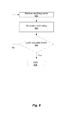
- FIG. 8 illustrates a process for generating a match rating based on consolidating the ratings from the comparisons between columns of the selected databases according to an embodiment of the present invention.
- FIG. 9 illustrates an example table of a mapping proposal according to an embodiment of the present invention.
- FIG. 10 illustrates hardware used to implement embodiments of the present invention.
- Described herein are techniques for performing data analysis for model proposals.
- the apparatuses, methods, and techniques described below may be implemented as a computer program (software) executing on one or more computers.
- the computer program may further be stored on a computer readable medium.
- the computer readable medium may include instructions for performing the processes described below.
- FIG. 1 is a schematic representation of a system 100 for performing data analysis for model proposals according to an embodiment of the present invention.
- System 100 includes a user or other interface 105 , a warehouse data store 108 , a local data store 110 , and a mapping model system 112 .
- the term “local data store” is used interchangeably with “local database,” and the term “warehouse data store” is used interchangeably with “warehouse database.”
- Local data store 110 may comprise one or more local data stores. For clarity and simplicity, only two local data stores (i.e., local data store 110 a and local data store 110 b ) are shown.
- Warehouse data store 108 may comprise one or more warehouse data stores.
- Mapping model system 112 comprises information provider data 118 , local provider data 120 , a mapping proposal engine 125 , a composite provider data store including a composite provider model 124 , a mapping proposal engine 125 , and a controller 130 .
- mapping model system 112 accesses the contents of warehouse database 108 and local database 110 over data flow paths 134 and 135 , respectively, when generating mapping proposals.
- Information provider data 118 is a set of data that is stored in warehouse database 108 .
- Local provider data 120 is a set of data that is stored in local database 110 .
- Local database 110 may be of a file type (e.g., a comma-separated values (CSV) file, or a spreadsheet file, such as a Microsoft® Excel file) that is different from the file type of warehouse database 108 .
- CSV comma-separated values
- a composite provider model 124 is a model that combines data from information provider data 118 or local provider data 120 or both.
- Mapping proposal engine 125 executes a process or algorithm that analyzes data sets from information provider data 118 , data sets from local provider data 120 , and current or previous composite provider model 124 and generates a proposed composite provider model 124 based on the analysis.
- Mapping proposal engine 125 analyzes various properties of the data sets for generating the proposed composite provider model 124 .
- Mapping proposal engine 125 combines data from multiple databases 108 and 110 by performing automated data analyses of the data with little or no interaction by the user, and generates and provides to the user proposed composite provider model 124 with suggested mappings that are semantically and logically correct with minimal or no post-analysis interaction by the user.
- User or other interface 105 is a collection of one or more data input/output devices for interacting with a human user or with another data processing system to receive and output data.
- interface 105 can be a presentation system, one or more software applications, or a data communications gateway, for example.
- Data flow path 132 is data communicated over interface 105 that retrieves data from or causes a change to data stored in local database 110 . Such changes include the insertion, deletion, or modification of all or a portion of the contents of local database 110 .
- Data output over interface 105 can present the results of data processing activities in system 100 .
- data flow path 133 can convey the results of queries or other operations performed on mapping model system 112 for presentation on a monitor or a data communications gateway.
- Warehouse data store 108 is a collection of information that is stored at one or more data machine readable storage devices (e.g., data stores).
- warehouse data store 108 may be a single data store or multiple data stores, which may be coupled to one or more software applications for storing application data.
- warehouse data store 108 stores the information in one or more models.
- warehouse data store 108 may store data as a plurality of data records. Each data record comprises a plurality of data elements (e.g., fields of a record).
- warehouse data store 108 may include different structures and their relations (e.g., data store tables, data records, fields, and foreign key relations). Additionally, different structures and fields may include data types, descriptions, or other metadata, for example, which may be different for different models.
- Data flow path 134 conveys information describing changes to data stored in warehouse data store 108 between mapping model system 112 and warehouse data store 108 Such changes include the insertion, deletion, and modification of all or a portion of the contents of one or more warehouse data stores.
- Local data store 110 is a collection of information that is stored at one or more data machine readable storage devices (e.g., data stores). Local data store 110 may be a single data store or multiple data stores, which may be coupled to one or more software applications for storing application data. Local data store 110 stores the information in one or more models. Local data store 110 may store data as a plurality of data records. Each data record comprises a plurality of data elements (e.g., fields of a record). Local data store 110 may include different structures and their relations (e.g., data store tables, data records, fields, and foreign key relations). Additionally, different structures and fields may include data types, descriptions, or other metadata, for example, which may be different for different models. Data flow path 135 conveys information describing changes to data stored in local data store 110 between mapping model system 112 and local data store 110 Such changes include the insertion, deletion, and modification of all or a portion of the contents of one or more local data stores.
- Mapping model system 112 is a collection of data processing activities (e.g., one or more data analysis programs or methods) performed in accordance with the logic of a set of machine-readable instructions.
- the data processing activities can include running queries on the contents of both warehouse data store 108 and local data store 110 .
- the results of such queries can be aggregated to yield an aggregated result set.
- a query is a request for information.
- a result set is a set of information that answers a query.
- An aggregated result set is a set of information from two or more data stores that answers a query, such as from warehouse data store 108 , a local data store 110 .
- the set of information in an aggregated result set can be, for example, a union of the results of independent queries on the two or more data stores.
- the aggregated result sets can be conveyed to interface 105 over data flow path 133 .
- Interface 105 can, in turn, render the aggregated result sets over an output device for a human or other user or to other systems.
- This output of aggregated result sets drawn from mapping model system 112 based on data from warehouse data store 108 and local data store 110 , allows system 100 to accurately portray the contents of different data stores having different data models.
- Controller 130 may be a component on the same system as a data warehouse or part of a different system and may be implemented in hardware, software, or as a combination of hardware and software, for example. Controller 130 receives a query from mapping proposal engine 125 and generates one or two requests based on the received query depending on whether one or both of warehouse data store 108 and local data store 110 are to be accessed. Warehouse data store 108 and local data store 110 transform the request from controller 130 into query syntax (e.g., SQL) compatible with the data store, and the SQL query may specify specific tables and fields to be read from the data store.
- query syntax e.g., SQL
- Controller 130 receives data from one or both of warehouse data store 108 and local data store 110 in response to the request. In responding to the query from mapping proposal engine 125 , controller 130 may aggregate the data from warehouse data store 108 and local data store 110 . The aggregation may be implemented with a union operation, for example. Finally, controller 130 returns the aggregated data to mapping proposal engine 125 in response to the query.
- FIG. 2 illustrates the mapping proposal engine 125 .
- Mapping proposal engine 125 comprises a warehouse model mapping engine 232 , a history mapping engine 234 , a metadata mapping engine 236 , and a data mapping engine 238 .
- the mapping engines of mapping proposal engine 125 analyze information provider data 118 , local provider data 120 , and composite provider model 124 and generate a model for combination of the selected data based on the selected properties.
- a first property is a data warehouse model in warehouse database 108 that may be formed from a subset of information provider data 118 .
- Data warehouse model mapping engine 232 processes the mapping of the first property.
- Data warehouse model mapping engine 232 searches information provider data 118 for a current or previously existing model that uses a subset of the selected set of information provider data 118 .
- Data warehouse model mapping engine 232 may also use metadata information 221 of information provider data 118 and metadata information 222 of local provider data 120 for generating the composite provider model 124 .
- data warehouse model mapping engine 232 uses the binding type and the column pairs used for the union/join condition in the model to generate a rating (e.g., a positive rating, such as described below on conjunction with FIG. 7 ), and applies the rating to the selected set of information provider data 118 .
- information provider data 118 is maintained by an entity (such as an information technology group), other than the entity maintaining local provider data 120 .
- the data warehouse model mapping may be presumed to be valid by mapping proposal engine 125 . As described below in conjunction with FIG. 7 , the weighting of the data warehouse model mapping may be high because of the presumption of validity.
- a second property is currently or previously existing composite provider model 124 , which may be formed from a subset of information provider data 118 and local provider data 120 .
- History mapping engine 234 processes the mapping of the second property. History mapping engine 234 searches for a currently or previously existing model in composite provider model 124 that uses a subset of the selected set of information provider data 118 or the selected set of local provider data 120 , or both. Current or previous composite provider model 124 that represents valid combinations of data may provide a template for history mapping engine 234 to generate a new composite provider model 124 with a similar set of information provider data 118 or local provider data 120 . History mapping engine 234 may also use metadata information 221 of information provider data 118 and metadata information 222 of local provider data 120 for generating the composite provider model 124 .
- history mapping engine 234 uses the binding type and the column pairs used for the union/join condition in composite provider model 124 to generate a rating (e.g., a positive rating, such as described below on conjunction with FIG. 7 ), and applies the rating to the selected set of information provider data 118 or the selected set of local provider data 120 or both.
- a rating e.g., a positive rating, such as described below on conjunction with FIG. 7
- a third property is metadata information 221 of information provider data 118 and metadata information 222 of local provider data 120 .
- Metadata mapping engine 236 processes the mapping of the third property.
- Metadata mapping engine 236 compares the columns of information provider data 118 and local provider data 120 on a metadata level (e.g. the name of the column or the description). If two columns have a high similarity based on the comparison, metadata mapping engine 236 rates a union/join condition based on this pair of columns with, for example, a positive rating. Otherwise, if there is no similarity, metadata mapping engine 236 rates the join condition with a rating that is, for example, negative.
- a fourth property is content data 225 of information provider data 118 and connect data 226 of local provider data 120 .
- Data mapping engine 238 processes the mapping of the fourth property.
- Data mapping engine 238 compares the content of the columns of information provider data 118 and local provider data 120 .
- Data mapping engine 238 uses the comparison to determine a rating based on the amount of data that is common between information provider data 118 and local provider data 120 . In the illustrative rating system described below on conjunction with FIG. 7 , no common data results into a negative rating, and the rating is otherwise positive. If two columns have common data, a join condition using these columns is valid, and the result set is non-empty.
- the data mapping property is not used to determine a rating regarding the binding type.
- information provider data 118 is indexed for searching.
- FIG. 3 illustrates a process for data modeling according to an embodiment of the present invention.
- the process illustrated in FIG. 3 is described using the example data illustrated in FIGS. 4-6 , which are example tables for warehouse database 108 , local database 110 a , and local database 110 b , respectively.
- FIG. 4 illustrates example table data for warehouse data store 108 .
- the data is maintained and stored in data warehouse database 108 .
- the table has a granularity that includes calendar day, customer identification, customer home country, customer industry segment, product, product group, sales channel, country version, amount sold and net sales.
- FIG. 5 illustrates a first example table data for local data store 110 .
- the data is maintained and stored in local database 110 .
- the table has a granularity that includes customer and rating. As can be seen, the table of FIG. 4 has higher and different granularity than the table of FIG. 5 .
- FIG. 6 illustrates a second example table for local data store 110 .
- the data is maintained and stored in local database 110 .
- the table has a granularity that includes customer, sales representative, and team. As can be seen, the table of FIG. 4 has higher and different granularity than the table of FIG. 6 .
- the databases that are to be combined are selected.
- one or more of local database 110 or warehouse database 108 or both are selected.
- the user selects the databases.
- the user selects the databases shown in FIG. 4 from data warehouse 108 and the two databases shown in FIGS. 5-6 from local database 110 .
- the user selects the databases from local database 110
- mapping proposal engine 125 selects the databases from warehouse database 108 .
- the properties that are to be used for the analysis are selected.
- the user or mapping proposal engine 125 may select some or all of the properties.
- the properties may be warehouse data model, history, metadata, or content data.
- mapping proposal engine 125 independently analyzes the selected databases to determine similarities between the data based on the selected properties.
- mapping proposal engine 125 generates a rating for each property.
- One embodiment for generating ratings is described below in conjunction with FIG. 7 .
- data warehouse model mapping engine 232 generates a rating based on warehouse data
- history mapping engine 234 generates a rating based on a current or previously existing warehouse data model
- metadata mapping engine 236 generates a rating based on metadata information 221 and metadata information 222
- data mapping engine 238 generates a rating based on the content of the columns of information provider data 118 and local provider data 120 .
- mapping proposal engine 125 consolidates the ratings to form a match rating between columns of the selected databases for all possible column pairs. Illustrative embodiments for generating match ratings are described below in conjunction with FIG. 8 .
- mapping proposal engine 125 creates composite provider model 124 .
- Mapping proposal engine 125 maps the column x of the composite provider model 124 and the column y of the local provider data 120 with the overall highest rating are mapped, and excludes other possible matches, until no rating Rxy greater than zero remains.
- mapping model system 112 does not create composite provider model 124 and provides information about the ratings so the user can use this information in his modeling process.
- mapping proposal engine 125 checks composite provider model 124 for data integrity, such as valid aggregation. In some embodiments, mapping proposal engine 125 checks composite provider model 124 to determine whether every selected column of warehouse database 108 and local database 110 has a valid union/join condition.
- mapping proposal engine 125 may also exclude some of the properties from the main analyzing process, which may increase performance, or may exclude properties which lead to poor rating quality in certain circumstances.
- FIG. 7 illustrates a process for analyzing databases and generating a rating according to an embodiment of the present invention.
- Mapping proposal engine 125 independently analyzes each of these properties and generates a rating.
- mapping proposal engine 125 selects a property (e.g., property i) to use for analyzing data of databases 108 and 110 .
- mapping proposal engine 125 retrieves a column (e.g., column x) from the first selected database and a column (e.g., column y) from the second selected database.
- mapping proposal engine 125 compares a column (e.g., column x) from the first selected database and a column (e.g., column y) from the second selected database.
- mapping proposal engine 125 generates a rating regarding the binding type of any pair of data 118 , 120 and 124 (e.g., union/join) and a rating regarding which columns of the data sets should be used for the combination (e.g., a union/join condition).
- mapping proposal engine 125 normalizes the ratings to generate a normalized rating r i (x,y) which is the normalized rating r from the analysis of property i for column x and column y.
- the rating is normalized to a value between ⁇ 1 and 1, with 0 meaning the analysis result is neutral. For example, if the selected information provider data 118 has never been modeled in composite provider model 124 , the rating for a history mapping analysis is neutral because mapping proposal engine 125 has no information to base a rating on.
- FIG. 8 illustrates a process for generating a match rating based on consolidating the ratings from the comparisons between columns of the selected databases. For example, the comparison is between a column of local provider data 120 and a column of composite provider model 124 .
- mapping proposal engine 125 retrieves a weighting vector for the selected properties of the selected databases.
- Each property i is labeled with a weight attribute defining its importance: Columns that have common data or have been previously combined in warehouse database 108 are more likely to be a good match, and to be a better match than other mappings, such as metadata matching (e.g., similar column names).
- the weight vector w is based on a priori knowledge of properties of local database 110 .
- the weight vector is:
- W W is the weight of the data warehouse model from the data warehouse mapping engine 232
- W D is the weight of the data mapping model from the data mapping engine 238
- W H is the weight of the history mapping model from the history mapping engine 234
- W M is the weight of the metadata mapping model from the metadata mapping engine 236 .
- the weigh vector w may be selected to provide significant differences (such as an order of magnitude) in the weights for the mapping.
- the weight vector w is:
- mapping proposal engine 125 generates a match rating for the compared columns for all properties based on the rating for each property.
- the match rating is based on weighting of the properties.
- mapping proposal engine 125 generates a match ranking using the following equation:
- R xy is a match rating for column x of composite provider model 124 and column y of local provider data 120
- w i is a weight for the property i
- r i (x,y) is the normalized rating of property i generated at 710 (see FIG. 7 ).
- the weighting vector is retrieved at 802 for the next column pair. Otherwise, at 806 , if the last column pair has been analyzed, at 808 , the match ratings are completed.
- the rating of the data mapping by data mapping engine 238 indicates that the columns have no common data, the rating is negative.
- even positive ratings from the history mapping analysis by history mapping engine 234 and/or the metadata mapping analysis by metadata mapping engine 236 does not result in a positive final rating.
- the rating for the data mapping by the data mapping engine 238 rating indicates that two columns of composite provider model 124 have the same content as the column of local provider data 120 , but one column of the composite provider model 124 has a higher metadata mapping rating by metadata mapping engine 236 , (e.g. because their names are identical). In this example, the final rating is higher, and the analysis results in a better match.
- FIG. 9 illustrates a table of the result of mapping proposal engine 125 .
- mapping proposal engine 125 uses the data of the illustrative examples of FIGS. 4-6 to display the mapping results of mapping proposal engine 125 including the possible matches between the “revenue figures” of the information provider data 118 and the “customer rankings” of local provider data 120 , restricted to the column “Customer” of the local provider data 120 .
- mapping proposal engine 125 maps the “Customer” column of local database 110 that includes “customer rankings” and the “Customer ID” column of information provider data 118 that includes “revenue figures.”
- FIG. 10 illustrates hardware used to implement embodiments of the present invention.
- An example computer system 1010 is illustrated in FIG. 10 .
- Computer system 1010 includes a bus 1005 or other communication mechanism for communicating information, and one or more processors 1001 coupled with bus 1005 for processing information.
- Computer system 1010 also includes a memory 1002 coupled to bus 1005 for storing information and instructions to be executed by processor 1001 , including information and instructions for performing the techniques described above, for example.
- This memory may also be used for storing variables or other intermediate information during execution of instructions to be executed by processor 1001 . Possible implementations of this memory may be, but are not limited to, random access memory (RAM), read only memory (ROM), or both.
- a machine readable storage device 1003 is also provided for storing information and instructions.
- Storage devices include, for example, a non-transitory electromagnetic medium such as a hard drive, a magnetic disk, an optical disk, a CD-ROM, a DVD, a flash memory, a USB memory card, or any other medium from which a computer can read.
- Storage device 1003 may include source code, binary code, or software files for performing the techniques above, for example.
- Storage device 1003 and memory 1002 are both examples of computer readable mediums.
- Computer system 1010 may be coupled via bus 1005 to a display 1012 , such as a cathode ray tube (CRT) or liquid crystal display (LCD), for displaying information to a computer user.
- a display 1012 such as a cathode ray tube (CRT) or liquid crystal display (LCD)
- An input device 1011 such as a keyboard and/or mouse is coupled to bus 1005 for communicating information and command selections from the user to processor 1001 .
- the combination of these components allows the user to communicate with the system, and may include, for example, user interface 105 .
- bus 1005 may be divided into multiple specialized buses.
- Computer system 1010 also includes a network interface 1004 coupled with bus 1005 .
- Network interface 1004 may provide two-way data communication between computer system 1010 and the local network 1020 , for example.
- the network interface 1004 may be a digital subscriber line (DSL) or a modem to provide data communication connection over a telephone line, for example.
- DSL digital subscriber line
- Another example of the network interface is a local area network (LAN) card to provide a data communication connection to a compatible LAN.
- LAN local area network
- Wireless links are another example.
- network interface 1004 sends and receives electrical, electromagnetic, or optical signals that carry digital data streams representing various types of information.
- Computer system 1010 can send and receive information, including messages or other interface actions, through the network interface 1004 across a local network 1020 , an Intranet, or the Internet 1030 .
- computer system 1010 may communicate with a plurality of other computer machines, such as server 1015 .
- server 1015 may be programmed with processes described herein.
- software components or services may reside on multiple different computer systems 1010 or servers 1031 - 1035 across the network. Some or all of the processes described above may be implemented on one or more servers, for example.
- local data store 110 and mapping model system 112 might be located on different computer systems 1010
- warehouse data store 108 may be on one or more servers 1015 and 1031 - 1035 , for example:
- a server 1031 may transmit actions or messages from one component, through Internet 1030 , local network 1020 , and network interface 1004 to a component on computer system 1010 .
- the software components and processes described above may be implemented on any computer system and send and/or receive information across a network, for example.
Abstract
Description
where WW is the weight of the data warehouse model from the data
where Rxy is a match rating for column x of
Claims (17)
Priority Applications (1)
| Application Number | Priority Date | Filing Date | Title |
|---|---|---|---|
| US13/473,860 US9098550B2 (en) | 2012-05-17 | 2012-05-17 | Systems and methods for performing data analysis for model proposals |
Applications Claiming Priority (1)
| Application Number | Priority Date | Filing Date | Title |
|---|---|---|---|
| US13/473,860 US9098550B2 (en) | 2012-05-17 | 2012-05-17 | Systems and methods for performing data analysis for model proposals |
Publications (2)
| Publication Number | Publication Date |
|---|---|
| US20130311456A1 US20130311456A1 (en) | 2013-11-21 |
| US9098550B2 true US9098550B2 (en) | 2015-08-04 |
Family
ID=49582170
Family Applications (1)
| Application Number | Title | Priority Date | Filing Date |
|---|---|---|---|
| US13/473,860 Active 2032-10-07 US9098550B2 (en) | 2012-05-17 | 2012-05-17 | Systems and methods for performing data analysis for model proposals |
Country Status (1)
| Country | Link |
|---|---|
| US (1) | US9098550B2 (en) |
Cited By (1)
| Publication number | Priority date | Publication date | Assignee | Title |
|---|---|---|---|---|
| US10394931B2 (en) | 2013-12-19 | 2019-08-27 | International Business Machines Corporation | Balancing provenance and accuracy tradeoffs in data modeling |
Families Citing this family (6)
| Publication number | Priority date | Publication date | Assignee | Title |
|---|---|---|---|---|
| US11100523B2 (en) * | 2012-02-08 | 2021-08-24 | Gatsby Technologies, LLC | Determining relationship values |
| JP6173896B2 (en) * | 2013-12-10 | 2017-08-02 | 株式会社日立製作所 | Data processing method and data processing server |
| KR102148984B1 (en) * | 2014-05-29 | 2020-08-27 | 삼성에스디에스 주식회사 | System and method for processing data |
| US10289725B2 (en) | 2014-11-25 | 2019-05-14 | Sap Se | Enterprise data warehouse model federation |
| US20160162480A1 (en) * | 2014-12-03 | 2016-06-09 | Hans-Peter Schaerges | Adaptive computerized mapping technique in database systems |
| US11755754B2 (en) * | 2018-10-19 | 2023-09-12 | Oracle International Corporation | Systems and methods for securing data based on discovered relationships |
Citations (7)
| Publication number | Priority date | Publication date | Assignee | Title |
|---|---|---|---|---|
| US5701453A (en) * | 1993-07-01 | 1997-12-23 | Informix Software, Inc. | Logical schema to allow access to a relational database without using knowledge of the database structure |
| US20040213455A1 (en) * | 2003-02-25 | 2004-10-28 | Parascript Llc | Training an on-line handwriting recognizer |
| US20050267687A1 (en) * | 2002-12-26 | 2005-12-01 | National Institute Of Advanced Industrial Science And Technology | System for predicting three-dimensional structure of protein |
| US20050278139A1 (en) * | 2004-05-28 | 2005-12-15 | Glaenzer Helmut K | Automatic match tuning |
| US20070005154A1 (en) * | 2003-08-28 | 2007-01-04 | Cerner Innovation, Inc. | System and method for multidimensional extension of database information using inferred groupings |
| US20080294620A1 (en) * | 2007-05-23 | 2008-11-27 | Microsoft Corporation | User-defined relevance ranking for search |
| US20100125613A1 (en) * | 2008-11-14 | 2010-05-20 | Microsoft Corporation | Method and system for rapid and cost-effective development of user generated content |
-
2012
- 2012-05-17 US US13/473,860 patent/US9098550B2/en active Active
Patent Citations (7)
| Publication number | Priority date | Publication date | Assignee | Title |
|---|---|---|---|---|
| US5701453A (en) * | 1993-07-01 | 1997-12-23 | Informix Software, Inc. | Logical schema to allow access to a relational database without using knowledge of the database structure |
| US20050267687A1 (en) * | 2002-12-26 | 2005-12-01 | National Institute Of Advanced Industrial Science And Technology | System for predicting three-dimensional structure of protein |
| US20040213455A1 (en) * | 2003-02-25 | 2004-10-28 | Parascript Llc | Training an on-line handwriting recognizer |
| US20070005154A1 (en) * | 2003-08-28 | 2007-01-04 | Cerner Innovation, Inc. | System and method for multidimensional extension of database information using inferred groupings |
| US20050278139A1 (en) * | 2004-05-28 | 2005-12-15 | Glaenzer Helmut K | Automatic match tuning |
| US20080294620A1 (en) * | 2007-05-23 | 2008-11-27 | Microsoft Corporation | User-defined relevance ranking for search |
| US20100125613A1 (en) * | 2008-11-14 | 2010-05-20 | Microsoft Corporation | Method and system for rapid and cost-effective development of user generated content |
Cited By (2)
| Publication number | Priority date | Publication date | Assignee | Title |
|---|---|---|---|---|
| US10394931B2 (en) | 2013-12-19 | 2019-08-27 | International Business Machines Corporation | Balancing provenance and accuracy tradeoffs in data modeling |
| US11222731B2 (en) | 2013-12-19 | 2022-01-11 | International Business Machines Corporation | Balancing provenance and accuracy tradeoffs in data modeling |
Also Published As
| Publication number | Publication date |
|---|---|
| US20130311456A1 (en) | 2013-11-21 |
Similar Documents
| Publication | Publication Date | Title |
|---|---|---|
| US20220035815A1 (en) | Processing database queries using format conversion | |
| US20220284014A1 (en) | Deriving metrics from queries | |
| US11681694B2 (en) | Systems and methods for grouping and enriching data items accessed from one or more databases for presentation in a user interface | |
| US11921715B2 (en) | Search integration | |
| US9098550B2 (en) | Systems and methods for performing data analysis for model proposals | |
| US9582553B2 (en) | Systems and methods for analyzing existing data models | |
| US10452639B2 (en) | Processing joins in a database system using zero data records | |
| US8682923B2 (en) | Set-level comparisons in dynamically formed groups | |
| US8843436B2 (en) | Systems and methods for performing direct reporting access to transaction databases | |
| JP6434154B2 (en) | Identifying join relationships based on transaction access patterns | |
| US11455283B2 (en) | Candidate element selection using significance metric values | |
| US20150081353A1 (en) | Systems and Methods for Interest-Driven Business Intelligence Systems Including Segment Data | |
| US20210397601A1 (en) | Enforcing path consistency in graph database path query evaluation | |
| US8589451B1 (en) | Systems and methods for generating a common data model for relational and object oriented databases | |
| US10983997B2 (en) | Path query evaluation in graph databases | |
| US10922328B2 (en) | Method and system for implementing an on-demand data warehouse | |
| Chavarría-Miranda et al. | Graql: A query language for high-performance attributed graph databases | |
| US20160379148A1 (en) | System and Methods for Interest-Driven Business Intelligence Systems with Enhanced Data Pipelines | |
| US10255316B2 (en) | Processing of data chunks using a database calculation engine | |
| US11822582B2 (en) | Metadata clustering | |
| US11500933B2 (en) | Techniques to generate and store graph models from structured and unstructured data in a cloud-based graph database system | |
| US20230185797A1 (en) | Systems and methods for generation and display of query visualizations | |
| US11947537B1 (en) | Automatic index management for a non-relational database | |
| WO2023114908A1 (en) | Systems and methods for generation and display of query visualizations | |
| Todoranova | Trends in the Development of Business Intelligence Systems |
Legal Events
| Date | Code | Title | Description |
|---|---|---|---|
| AS | Assignment |
Owner name: SAP AG, GERMANY Free format text: ASSIGNMENT OF ASSIGNORS INTEREST;ASSIGNORS:WINKLER, PATRICK;NAGEL, KLAUS;HOEPFNER, MARCUS;REEL/FRAME:028225/0364 Effective date: 20120510 |
|
| AS | Assignment |
Owner name: SAP SE, GERMANY Free format text: CHANGE OF NAME;ASSIGNOR:SAP AG;REEL/FRAME:033625/0223 Effective date: 20140707 |
|
| FEPP | Fee payment procedure |
Free format text: PAYOR NUMBER ASSIGNED (ORIGINAL EVENT CODE: ASPN); ENTITY STATUS OF PATENT OWNER: LARGE ENTITY |
|
| STCF | Information on status: patent grant |
Free format text: PATENTED CASE |
|
| FEPP | Fee payment procedure |
Free format text: PAYER NUMBER DE-ASSIGNED (ORIGINAL EVENT CODE: RMPN); ENTITY STATUS OF PATENT OWNER: LARGE ENTITY Free format text: PAYOR NUMBER ASSIGNED (ORIGINAL EVENT CODE: ASPN); ENTITY STATUS OF PATENT OWNER: LARGE ENTITY |
|
| MAFP | Maintenance fee payment |
Free format text: PAYMENT OF MAINTENANCE FEE, 4TH YEAR, LARGE ENTITY (ORIGINAL EVENT CODE: M1551); ENTITY STATUS OF PATENT OWNER: LARGE ENTITY Year of fee payment: 4 |
|
| MAFP | Maintenance fee payment |
Free format text: PAYMENT OF MAINTENANCE FEE, 8TH YEAR, LARGE ENTITY (ORIGINAL EVENT CODE: M1552); ENTITY STATUS OF PATENT OWNER: LARGE ENTITY Year of fee payment: 8 |