US9098466B2 - Switching between mirrored volumes - Google Patents

Switching between mirrored volumes Download PDF

Info

Publication number
US9098466B2
US9098466B2 US13/663,221 US201213663221A US9098466B2 US 9098466 B2 US9098466 B2 US 9098466B2 US 201213663221 A US201213663221 A US 201213663221A US 9098466 B2 US9098466 B2 US 9098466B2
Authority
US
United States
Prior art keywords
pprc
volume
copy
volumes
primary
Prior art date
Legal status (The legal status is an assumption and is not a legal conclusion. Google has not performed a legal analysis and makes no representation as to the accuracy of the status listed.)
Expired - Fee Related, expires
Application number
US13/663,221
Other versions
US20140122816A1 (en
Inventor
Jeffrey M. BARNES
Gary S. DOMROW
Nicholas S. Ham
Carol S. Mellgren
Jared M. Minch
Stephen M. Tee
Current Assignee (The listed assignees may be inaccurate. Google has not performed a legal analysis and makes no representation or warranty as to the accuracy of the list.)
International Business Machines Corp
Original Assignee
International Business Machines Corp
Priority date (The priority date is an assumption and is not a legal conclusion. Google has not performed a legal analysis and makes no representation as to the accuracy of the date listed.)
Filing date
Publication date
Application filed by International Business Machines Corp filed Critical International Business Machines Corp
Priority to US13/663,221 priority Critical patent/US9098466B2/en
Assigned to INTERNATIONAL BUSINESS MACHINES CORPORATION reassignment INTERNATIONAL BUSINESS MACHINES CORPORATION ASSIGNMENT OF ASSIGNORS INTEREST (SEE DOCUMENT FOR DETAILS). Assignors: MELLGREN, CAROL S., BARNES, JEFFREY M., TEE, STEPHEN M., DOMROW, GARY S., HAM, NICHOLAS S., MINCH, JARED M.
Priority to CN201310518365.9A priority patent/CN103793271B/en
Publication of US20140122816A1 publication Critical patent/US20140122816A1/en
Application granted granted Critical
Publication of US9098466B2 publication Critical patent/US9098466B2/en
Expired - Fee Related legal-status Critical Current
Adjusted expiration legal-status Critical

Links

Images

Classifications

    • GPHYSICS
    • G06COMPUTING; CALCULATING OR COUNTING
    • G06FELECTRIC DIGITAL DATA PROCESSING
    • G06F11/00Error detection; Error correction; Monitoring
    • G06F11/07Responding to the occurrence of a fault, e.g. fault tolerance
    • G06F11/16Error detection or correction of the data by redundancy in hardware
    • G06F11/20Error detection or correction of the data by redundancy in hardware using active fault-masking, e.g. by switching out faulty elements or by switching in spare elements
    • G06F11/2053Error detection or correction of the data by redundancy in hardware using active fault-masking, e.g. by switching out faulty elements or by switching in spare elements where persistent mass storage functionality or persistent mass storage control functionality is redundant
    • G06F11/2056Error detection or correction of the data by redundancy in hardware using active fault-masking, e.g. by switching out faulty elements or by switching in spare elements where persistent mass storage functionality or persistent mass storage control functionality is redundant by mirroring
    • G06F11/2069Management of state, configuration or failover
    • GPHYSICS
    • G06COMPUTING; CALCULATING OR COUNTING
    • G06FELECTRIC DIGITAL DATA PROCESSING
    • G06F11/00Error detection; Error correction; Monitoring
    • G06F11/07Responding to the occurrence of a fault, e.g. fault tolerance
    • G06F11/16Error detection or correction of the data by redundancy in hardware
    • G06F11/20Error detection or correction of the data by redundancy in hardware using active fault-masking, e.g. by switching out faulty elements or by switching in spare elements
    • G06F11/2053Error detection or correction of the data by redundancy in hardware using active fault-masking, e.g. by switching out faulty elements or by switching in spare elements where persistent mass storage functionality or persistent mass storage control functionality is redundant
    • G06F11/2056Error detection or correction of the data by redundancy in hardware using active fault-masking, e.g. by switching out faulty elements or by switching in spare elements where persistent mass storage functionality or persistent mass storage control functionality is redundant by mirroring
    • G06F11/2071Error detection or correction of the data by redundancy in hardware using active fault-masking, e.g. by switching out faulty elements or by switching in spare elements where persistent mass storage functionality or persistent mass storage control functionality is redundant by mirroring using a plurality of controllers
    • G06F11/2076Synchronous techniques
    • GPHYSICS
    • G06COMPUTING; CALCULATING OR COUNTING
    • G06FELECTRIC DIGITAL DATA PROCESSING
    • G06F11/00Error detection; Error correction; Monitoring
    • G06F11/006Identification
    • GPHYSICS
    • G06COMPUTING; CALCULATING OR COUNTING
    • G06FELECTRIC DIGITAL DATA PROCESSING
    • G06F12/00Accessing, addressing or allocating within memory systems or architectures
    • G06F12/02Addressing or allocation; Relocation
    • G06F12/06Addressing a physical block of locations, e.g. base addressing, module addressing, memory dedication
    • G06F12/0615Address space extension
    • G06F12/0623Address space extension for memory modules
    • GPHYSICS
    • G06COMPUTING; CALCULATING OR COUNTING
    • G06FELECTRIC DIGITAL DATA PROCESSING
    • G06F13/00Interconnection of, or transfer of information or other signals between, memories, input/output devices or central processing units
    • G06F13/14Handling requests for interconnection or transfer
    • G06F13/20Handling requests for interconnection or transfer for access to input/output bus
    • GPHYSICS
    • G06COMPUTING; CALCULATING OR COUNTING
    • G06FELECTRIC DIGITAL DATA PROCESSING
    • G06F13/00Interconnection of, or transfer of information or other signals between, memories, input/output devices or central processing units
    • G06F13/38Information transfer, e.g. on bus
    • GPHYSICS
    • G06COMPUTING; CALCULATING OR COUNTING
    • G06FELECTRIC DIGITAL DATA PROCESSING
    • G06F3/00Input arrangements for transferring data to be processed into a form capable of being handled by the computer; Output arrangements for transferring data from processing unit to output unit, e.g. interface arrangements
    • G06F3/06Digital input from, or digital output to, record carriers, e.g. RAID, emulated record carriers or networked record carriers
    • G06F3/0601Interfaces specially adapted for storage systems
    • G06F3/0602Interfaces specially adapted for storage systems specifically adapted to achieve a particular effect
    • G06F3/062Securing storage systems
    • GPHYSICS
    • G06COMPUTING; CALCULATING OR COUNTING
    • G06FELECTRIC DIGITAL DATA PROCESSING
    • G06F3/00Input arrangements for transferring data to be processed into a form capable of being handled by the computer; Output arrangements for transferring data from processing unit to output unit, e.g. interface arrangements
    • G06F3/06Digital input from, or digital output to, record carriers, e.g. RAID, emulated record carriers or networked record carriers
    • G06F3/0601Interfaces specially adapted for storage systems
    • G06F3/0628Interfaces specially adapted for storage systems making use of a particular technique
    • G06F3/0646Horizontal data movement in storage systems, i.e. moving data in between storage devices or systems
    • G06F3/065Replication mechanisms
    • GPHYSICS
    • G06COMPUTING; CALCULATING OR COUNTING
    • G06FELECTRIC DIGITAL DATA PROCESSING
    • G06F3/00Input arrangements for transferring data to be processed into a form capable of being handled by the computer; Output arrangements for transferring data from processing unit to output unit, e.g. interface arrangements
    • G06F3/06Digital input from, or digital output to, record carriers, e.g. RAID, emulated record carriers or networked record carriers
    • G06F3/0601Interfaces specially adapted for storage systems
    • G06F3/0668Interfaces specially adapted for storage systems adopting a particular infrastructure

Definitions

  • the present invention relates in general to computers, and more particularly to switching between mirrored volumes in a computing environment.
  • Computer systems In today's society, computer systems are commonplace. Computer systems may be found in the workplace, at home, or at school. Computer systems may include data storage systems, or disk storage systems, to process and store data.
  • a storage system may include various storage components, such as one or more disk drives configured in a storage environment.
  • the storage environment may include a number of disk drives implemented in an array, such as a Redundant Array of Independent Disks (RAID) topology, to provide data security in the event of a hardware or software failure.
  • RAID Redundant Array of Independent Disks
  • the storage environment may also include other storage components, such as controllers and interfaces to manage the flow of data.
  • the computer system may include a complex data processing system or computing environment. A data processing system often requires computational resources or availability requirements that cannot be achieved by a single computer.
  • Information technology systems may need protection from site disasters or outages, where outages may be planned or unplanned.
  • information technology systems may require features for data migration, data backup, or data duplication.
  • Implementations for disaster or outage recovery, data migration, data backup, and data duplication may include mirroring or copying of data in storage systems. Such mirroring or copying of data may involve interactions among hosts, storage systems and connecting networking components of the information technology system.
  • a method for switching between mirrored volumes, in a computing environment, is provided.
  • a copy relation identification ID
  • I/O input/output
  • a computer system switching between mirrored volumes, in a computing environment.
  • the computer system includes a computer-readable medium and a processor in operable communication with the computer-readable medium.
  • the processor creates a copy relation identification (ID) between mirrored volumes for using the copy relation ID in conjunction with a multi-path device driver for switching input/output (I/O) for applications between a first path to a second path between the mirrored volumes.
  • ID copy relation identification
  • I/O input/output
  • a computer program product for switching between mirrored volumes, in a computing environment.
  • the computer-readable storage medium has computer-readable program code portions stored thereon.
  • the computer-readable program code portions include a first executable portion that creates a copy relation identification (ID) between mirrored volumes for using the copy relation ID in conjunction with a multi-path device driver for switching input/output (I/O) for applications between a first path to a second path between the mirrored volumes.
  • ID copy relation identification
  • I/O input/output
  • FIG. 1A is a block diagram illustrating a computing system environment having an example storage device in which aspects of the present invention may be realized;
  • FIG. 1B is a block diagram illustrating an alternative computing system environment having an example storage device in which aspects of the present invention may be realized;
  • FIG. 2 is a block diagram illustrating a hardware structure of data storage system in a computer system in which aspects of the present invention may be realized;
  • FIG. 3 is a flowchart illustrating an exemplary method for switching between mirrored volumes in a computing environment in which aspects of the present invention may be realized;
  • FIG. 4 is a flowchart illustrating an exemplary alternative method for switching between mirrored volumes in a computing environment in which aspects of the present invention may be realized.
  • FIG. 5 is a flowchart illustrating an alternative exemplary method for switching between mirrored volumes in a computing environment in which aspects of the present invention may be realized.
  • a computer system may include a complex data processing system or computing environment.
  • An enterprise storage server such as the IBM® TotalStorage Enterprise Storage Server®, may be a disk storage server that includes one or more processors coupled to storage devices, including high capacity scalable storage devices, Redundant Array of Independent Disks (RAID), etc.
  • the enterprise storage servers are connected to a network and include features for copying data in storage systems.
  • Peer-to-Peer Remote Copy is an ESS function that allows the shadowing of application system data from a first site to a second site.
  • the first site may be referred to as an application site, a local site, or a primary site.
  • the second site may be referred to as a recovery site, a remote site or a secondary site.
  • the logical volumes that hold be data in the ESS at the local site are called local volumes, and the corresponding logical volumes that hold the mirrored data at the remote site are called remote volumes.
  • High speed links, such as ESCON links may connect the local and remote ESS systems.
  • ESS currently supports a host reading directly from a secondary PPRC device.
  • a peer-to-peer remote copy over fibre channel protocol (PPRC/FCP) relationship is typically established from a primary storage device to a secondary storage device in a PPRC operating environment.
  • PPRC/FCP peer-to-peer remote copy over fibre channel protocol
  • both the host and the PPRC/FCP primary may have concurrent access to the PPRC/FCP secondary device.
  • the secondary is a target device for both the primary and an independent Host System.
  • a copy relation identification is created between mirrored volumes for using the copy relation ID in conjunction with a multi-path device driver for switching input/output (I/O) for applications between a first path to a second path between the mirrored volumes.
  • the Copy Relation Id may be used in conjunction with multi-path device driver on the host system to provide a simple and non-disruptive way to move all applications from one logical unit number (LUN) to a mirrored LUN at a separate site.
  • the multi-path device driver function will swap I/O from one LUN to its mirrored LUN using function similar to the multi-path function to switch the I/O from one path to another path for a single LUN.
  • a rack-power control module (RPC) module is used for allowing a local storage partition, located on a local server, for controlling a destination storage partition, located on a destination server, by piggybacking commands on power alerts issued by the RPC module in a clustered storage system.
  • the RPC module is used as a way for a partition in a server to inform/control another partition (e.g., a partner partition) running on another server.
  • the computer system 50 includes central processing unit (CPU) 52 , which is connected to communication port 58 and memory device 56 .
  • the communication port 58 is in communication with a communication network 60 .
  • the communication network 60 and storage network may be configured to be in communication with server (hosts) 64 and storage systems, which may include storage devices 54 .
  • the storage systems may include hard disk drive (HDD) devices, solid-state devices (SSD) etc., which may be configured in a redundant array of independent disks (RAID).
  • HDD hard disk drive
  • SSD solid-state devices
  • RAID redundant array of independent disks
  • the operations as described below may be executed on storage device(s) 54 , located in system 50 or elsewhere and may have multiple memory devices 56 working independently and/or in conjunction with other CPU devices 52 .
  • Memory device 56 may include such memory as electrically erasable programmable read only memory (EEPROM) or a host of related devices. Memory device 56 and storage devices 54 are connected to CPU 52 via a signal-bearing medium. In addition, CPU 52 is connected through communication port 58 to a communication network 60 , having an attached plurality of additional computer host systems 64 . In addition, memory device 56 and the CPU 52 may be embedded and included in each component of the computing system 50 . Each storage system may also include separate and/or distinct memory devices 56 and CPU 52 that work in conjunction or as a separate memory device 56 and/or CPU 52 .
  • EEPROM electrically erasable programmable read only memory
  • FIG. 1B is a block diagram illustrating an alternative computing system environment having an example storage device in which aspects of the present invention may be realized.
  • Hosts 4 a, b may comprise any computing device known in the art, including servers through which other client computers can access storage or clients.
  • the hosts 4 a , 4 b each include at least one adaptor, such as a Fibre Channel, SCSI adaptor card, or any other network adaptor card known in the art.
  • the host adaptors allow the hosts 4 a , 4 b to communicate with storage controllers 6 a, b via switches 8 a, b .
  • the switches 8 a, b may comprise the international Business Machines Corporation (IBM®) Fibre Channel Storage Hub or Switch, the IBM® SAN Fibre Channel Switch, or any other switching device known in the art.
  • Each switch 8 a, b has a port connecting to a network 12 , which may comprise any local area network, wide area network, the Internet or any other network system.
  • the network 12 may use routers and switches to dynamically determine the data path through the network 12 .
  • a primary controller 6 a includes interface cards 14 a and b having ports 16 a, b, c, d and a secondary controller 6 b includes interface cards 18 a and b having ports 20 a, b, c, d .
  • Primary controller 6 a would communicate with the secondary controller 6 b via one of the ports 16 a, b, c, d , switch 8 a , the network 12 , switch 8 b , and then one of the ports 20 a, b, c, d on the secondary controller 6 b .
  • the primary controller 6 a can select one of sixteen I/O paths to communicate with the secondary control 6 b , i.e., one of the ports 16 a, b, c, d paired with one of the ports 20 a, b, c, d .
  • each of the controllers 6 a, b may include a different number of interface cards having a different number of ports to provide more or less communication paths there between.
  • the secondary storage 10 b maintains a mirror copy of specified data volumes in the primary storage 10 a .
  • a relationship is established between primary volumes in the primary storage 10 a and corresponding secondary volumes in the secondary storage 10 b that mirror the primary volumes.
  • the primary controller 6 a will write any updates from hosts 4 a, b to primary volumes to the secondary controller 6 b to write to the secondary volumes in the secondary storage 10 b.
  • the primary and secondary controllers 6 a, b may include IBM® Peer-to-Peer Remote Copy (PPRC), Extended Remote Copy (XRC) software, or other vender shadowing software to allow communication between the controllers 6 a, b to coordinate data shadowing.
  • the controllers 6 a, b may comprise large scale storage controllers, such as the IBM® 3990 and Enterprise Storage System class controllers.
  • the primary and secondary controllers 6 a, b may comprise controllers from different vendors of different models, etc., and may not include any specialized protocol software for performing the backup operations. Further, the controllers may include any operating system known in the art, including the Microsoft® Corporation Windows® operating systems.
  • the primary controller 6 a can use commonly used write commands, such as SCSI write commands, to copy the primary volumes to the secondary volumes in the secondary storage 10 b .
  • the secondary controller 6 b does not need special purpose software to coordinate the shadowing activities with the primary controller 6 b as the primary controller 6 a accomplishes the shadowing by using standard write commands.
  • the primary and secondary controllers 6 a, b may comprise any controller device known in the art and the primary and secondary controllers 6 a, b may be of different models and model types, and even of different classes of storage controllers.
  • the host adapter associated with primary controller 6 a may be instructed by the application level to sends I/O commands (e.g., write commands) to the host adapter associated with secondary controller 6 b .
  • the host adapter associated with the primary controller 6 a sets a control flag in the write command to indicate that the command and data contain a special task identifier.
  • the host adapter associated with the primary controller 6 a copies the identifier into both the SCSI CDB and appends the same identifier to the end of the respective data frame.
  • the host adapter then sends the write command and data (including the identifier as part of the data) over network 12 and switch 8 b to the secondary controller 6 b.
  • the host adapter associated with secondary con roller 6 b receives the I/O (e.g., write) command.
  • the host adapter associate with secondary controller 6 b checks for the control flag to indicate that the command and data contain the special identifier, and determines the control flag is set.
  • the secondary controller 6 b host adapter compares the identifier in the SCSI CDB with the identifier appended at the end of the respective data frame. If the two identifiers match, the data is sent to cache, and good status notification is returned to primary controller 6 a . If the two identifiers do not match, a SCSI Check Condition is returned to the primary controller 6 a to indicate failure.
  • the identifier described above may vary according to a particular implementation.
  • information known to the secondary controller may be utilized.
  • the identifier may include a logical block address (LBA), volume identification (volume ID), and/or track identification (track ID) information.
  • the identifier may include a counter or count mechanism.
  • FIG. 2 is an exemplary block diagram 200 showing a hardware structure of a data storage system in a computer system according to the present invention.
  • Host computers 210 , 220 , 225 are shown, each acting as a central processing unit for performing data processing as part of a data storage system 200 .
  • the cluster hosts/nodes (physical or virtual devices), 210 , 220 , and 225 may be one or more new physical devices or logical devices to accomplish the purposes of the present invention in the data storage system 200 .
  • a data storage system 200 may be implemented as IBM® System StorageTM DS8000TM.
  • a Network connection 260 may be a fibre channel fabric, a fibre channel point to point link, a fibre channel over ethernet fabric or point to point link, a FICON or ESCON I/O interface, any other I/O interface type, a wireless network, a wired network, a LAN, a WAN, heterogeneous, homogeneous, public (i.e. the Internet), private, or any combination thereof.
  • the hosts, 210 , 220 , and 225 may be local or distributed among one or more locations and may be equipped with any type of fabric (or fabric channel) (not shown in FIG.
  • Data storage system 200 is accordingly equipped with a suitable fabric (not shown in FIG. 2 ) or network adaptor 260 to communicate.
  • Data storage system 200 is depicted in FIG. 2 comprising storage controllers 240 and cluster hosts 210 , 220 , and 225 .
  • the cluster hosts 210 , 220 , and 225 may include cluster nodes.
  • storage controller 240 is shown in FIG. 2 as a single processing unit, including a microprocessor 242 , system memory 243 and nonvolatile storage (“NVS”) 216 . It is noted that in some embodiments, storage controller 240 is comprised of multiple processing units, each with their own processor complex and system memory, and interconnected by a dedicated network within data storage system 200 .
  • Storage 230 (labeled as 230 a , 230 b , and 230 n in FIG. 3 ) may be comprised of one or more storage devices, such as storage arrays, which are connected to storage controller 240 (by a storage network) with one or more cluster hosts 210 , 220 , and 225 connected to each storage controller 240 .
  • Storage controller 240 manages storage 230 and facilitates the processing of write and read requests intended for storage 230 .
  • the system memory 243 of storage controller 240 stores program instructions and data, which the processor 242 may access for executing functions and method steps of the present invention for executing and managing storage 230 as described herein.
  • system memory 243 includes, is in association with, or is in communication with the operation software 250 for performing methods and operations described herein. As shown in FIG.
  • system memory 243 may also include or be in communication with a cache 245 for storage 230 , also referred to herein as a “cache memory”, for buffering “write data” and “read data”, which respectively refer to write/read requests and their associated data.
  • cache 245 is allocated in a device external to system memory 243 , yet remains accessible by microprocessor 242 and may serve to provide additional security against data loss, in addition to carrying out the operations as described in herein.
  • cache 245 is implemented with a volatile memory and non-volatile memory and coupled to microprocessor 242 via a local bus (not shown in FIG. 2 ) for enhanced performance of data storage system 200 .
  • the NVS 216 included in data storage controller is accessible by microprocessor 242 and serves to provide additional support for operations and execution of the present invention as described in other figures.
  • the NVS 216 may also be referred to as a “persistent” cache, or “cache memory” and is implemented with nonvolatile memory that may or may not utilize external power to retain data stored therein.
  • the NVS may be stored in and with the cache 245 for any purposes suited to accomplish the objectives of the present invention.
  • a backup power source (not shown in FIG. 2 ), such as a battery, supplies NVS 216 with sufficient power to retain the data stored therein in case of power loss to data storage system 200 .
  • the capacity of NVS 216 is less than or equal to the total capacity of cache 245 .
  • Storage 230 may be physically comprised of one or more storage devices, such as storage arrays.
  • a storage array is a logical grouping of individual storage devices, such as a hard disk.
  • storage 230 is comprised of a JBOD (Just a Bunch of Disks) array or a RAID (Redundant Array of Independent Disks) array.
  • a collection of physical storage arrays may be further combined to form a rank, which dissociates the physical storage from the logical configuration.
  • the storage space in a rank may be allocated into logical volumes, which define the storage location specified in a write/read request.
  • the storage system as shown in FIG. 2 may include a logical volume, or simply “volume,” may have different kinds of allocations.
  • Storage 230 a , 230 b and 230 n are shown as ranks in data storage system 200 , and are referred to herein as rank 230 a , 230 b and 230 n .
  • Ranks may be local to data storage system 200 , or may be located at a physically remote location. In other words, a local storage controller may connect with a remote storage controller and manage storage at the remote location.
  • Rank 230 a is shown configured with two entire volumes, 234 and 236 , as well as one partial volume 232 a .
  • Rank 230 b is shown with another partial volume 232 b .
  • volume 232 is allocated across ranks 230 a and 230 b .
  • Rank 230 n is shown as being fully allocated to volume 238 —that is, rank 230 n refers to the entire physical storage for volume 238 .
  • a rank may be configured to include one or more partial and/or entire volumes. Volumes and ranks may further be divided into so-called “tracks,” which represent a fixed block of storage. A track is therefore associated with a given volume and may be given a given rank.
  • the storage controller 240 may include a multi-path device driver 255 , a copy relation identification module 257 , and a PPRC module 259 .
  • the multi-path device driver 255 , the copy relation identification module 257 , and the PPRC module 259 may work in conjunction with each and every component of the storage controller 240 , the hosts 210 , 220 , 225 , and storage devices 230 .
  • Each distributed data processing node/hosts, 210 , 220 , and 225 is associated with a service processor/microprocessor 242 , e.g., service processors, each of which is responsible for booting its associated node and for assisting system-level service processor in monitoring each of the nodes; a service processor/microprocessor 242 may be associated with a node through a variety of physical connections to its associated node, e.g., the service processor's hardware card may attach to a PCI bus. It should be noted that each node may have a plurality of service processors/microprocessors 242 , although only one service processor would be responsible for booting its associated node.
  • the multi-path device driver 255 , the copy relation identification module 257 , and the PPRC module 259 may be structurally one complete module or may be associated and/or included with other individual modules.
  • the multi-path device driver 255 , the copy relation identification module 257 , and the PPRC module 259 may also be located in the cache 245 or other components.
  • the storage controller 240 includes a control switch 241 for controlling the fiber channel protocol to the host computers 210 , 220 , 225 , a microprocessor 242 for controlling all the storage controller 240 , a nonvolatile control memory 243 for storing a microprogram (operation software) 250 for controlling the operation of storage controller 240 , data for control, cache 245 for temporarily storing (buffering) data, and buffers 244 for assisting the cache 245 to read and write data, a control switch 241 for controlling a protocol to control data transfer to or from the storage devices 230 , the multi-path device driver 255 , the copy relation identification module 257 , and the PPRC module 259 , in which information may be set.
  • a control switch 241 for controlling the fiber channel protocol to the host computers 210 , 220 , 225
  • a microprocessor 242 for controlling all the storage controller 240
  • a nonvolatile control memory 243 for storing a microprogram (operation software) 250 for controlling
  • Multiple buffers 244 may be implemented with the present invention to assist with the operations as described herein.
  • the cluster hosts/nodes, 210 , 220 , 225 and the storage controller 240 are connected through a network adaptor (this could be a fibre channel) 260 as an interface i.e., via at least one switch called “fabric.”
  • the host computers or one or more physical or virtual devices, 210 , 220 , 225 and the storage controller 240 are connected through a network (this could be a fibre channel) 260 as an interface i.e., via at least one switch called “fabric.”
  • a network this could be a fibre channel
  • the microprocessor 242 may control the memory 243 to store command information from the host device (physical or virtual) 210 and information for identifying the host device (physical or virtual) 210 .
  • the control switch 241 , the buffers 244 , the cache 245 , the operating software 250 , the microprocessor 242 , memory 243 , NVS 216 , multi-path device driver 255 , the copy relation identification module 257 , and the PPRC module 259 are in communication with each other and may be separate or one individual component(s). Also, several, if not all of the components, such as the operation software 250 may be included with the memory 243 . Each of the components within the devices shown may be linked together and may be in communication with each other for purposes suited to the present invention.
  • the multi-path device driver 255 , the copy relation identification module 257 , and the PPRC module 259 may also be located in the cache 245 or other components. As such, one or more of the multi-path device driver 255 , the copy relation identification module 257 , and the PPRC module 259 maybe used as needed, based upon the storage architecture and users preferences.
  • FIG. 3 is a flowchart illustrating an exemplary method 300 for switching between mirrored volumes in a computing environment.
  • the method 300 begins (step 302 ) by creating a copy relation identification (ID) between mirrored volumes for using the copy relation ID in conjunction with a multi-path device driver for switching input/output (I/O) for applications between a first path to a second path between the mirrored volumes (step 304 ).
  • the method 300 ends (step 306 ).
  • FIG. 3 may be described with greater specificity as follows.
  • a unique name e.g., a copy relation Id or “CopyRelationId”
  • This copy relation Id is used to swap between the mirrored volumes without any application disruption.
  • the copy relation Id can move between volumes, and also to a volume that was not part of the original mirror relationship, and may still be used to identify Hyperswap capable volumes.
  • a copy relation Id is assigned to the PPRC primary and PPRC secondary.
  • the copy relation Id consists of the serial number of the primary PPRC and the timestamp of when the PPRC relation was created.
  • the copy relation Id is unique throughout the subsystems managed by a host system.
  • the copy relation Id is stored in metadata on both the PPRC primary and PPRC secondary so that the copy relation Id can be retained for the life of the host volume, regardless of what subsystem or site the physical volume resides in.
  • the copy relation Id is created for a volume when a volume changes from Simplex to PPRC primary. If the volume becomes Simplex again, it will still retain the copy relation Id so that the host access will not be interrupted. The copy relation Id will remain associated with the volume until a new PPRC relation is created for the volume. If a Hyperswap is performed, the PPRC secondary becomes the new PPRC primary and it will retain the same copy relation Id.
  • the hyperswap is a continuous availability solution wherein a set of nodes (and/or volumes) accessing a synchronously replicated storage system, containing a group of storage volumes, switch from a primary storage system to a secondary (replica) storage system, and must do so without any application outage in any node in the cluster.
  • the hyperswap operation may take place because of a storage system failure, known as an unplanned hyperswap, or under administrative control, known as a planned hyperswap.
  • the hyperswap operation may involve both boot volumes and non-boot volumes in the storage system.
  • the copy relation Id will be returned to the host as a vendor-specific designation descriptor within the Device Identification VPD page (page 83h).
  • This information is retained by the host system and used by multi-pathing drivers to switch from the PPRC primary to the PPRC secondary when timeouts or errors occur in communication with the PPRC primary.
  • the switch takes advantage of the Target Port Group state to have active paths from the host system to the PPRC primary and standby paths from the host system to the PPRC secondary.
  • the host system will switch to the PPRC secondary volume through the alternate path via the copy relation Id.
  • the CopyRelationId can be used in conjunction with Multi-path Device Drivers on the host system to provide a simple and non-disruptive way to move all applications from one LUN to a mirrored LUN at a separate site.
  • VPD inquiry vital product data
  • a standardized inquiry vital product data (VPD) page may contain various identifiers with different characteristics for a SCSI device being addressed, and/or for a logical unit (e.g., addressable blocks of storage created from one or more disks contained within a SCSI device, which may provide a unique connection to an application program or another SCSI device) being addressed on a SCSI device.
  • This page is called a Device Identification VPD page (described herein as “VPD 83h page”).
  • FIG. 4 is a flowchart illustrating an exemplary method 400 for switching between mirrored volumes in a computing environment in which aspects of the present invention may be realized.
  • the method 400 begins (step 402 ) by creating a copy relation identification (ID) (e.g., a unique name) for a peer-to-peer remote copy (PPRC) that includes a volume identification (ID) of a primary mirror and a unique ID of the mirror relationship (step 404 ). Assign the copy relation ID to a primary PPRC and a secondary PPRC (step 406 ).
  • ID copy relation identification
  • PPRC peer-to-peer remote copy
  • the copy relation ID is stored in metadata on both the primary PPRC and the secondary PPRC, and includes a serial number of the primary PPRC and a time stamp of the creation of a relationship between the primary PPRC and the secondary PPRC.
  • the method 400 determines if a volume is added to the mirrored relationship and/or changes from a simplex type volume to the peer-to-peer remote copy (PPRC) volume (step 407 ). If yes, the copy relation ID is created for and/or moved to the added volume (step 408 ). If no, the method 400 determines if any volume changes from the PPRC volume back to the simplex type volume (step 410 ).
  • step 412 the copy relation ID is retained by the volume thereby a host access is not interrupted. If no, the method 400 may jump to step 416 and determine if a hyperswap is performed (step 416 ). After step 412 , the method 400 may then retain the association between the volume and the copy relation ID until a new PPRC relation is created for the volume (step 414 ). From either step 406 , 410 , and/or 414 , the method 400 may the determine if a hyperswap is performed (step 416 ).
  • the method switches the peer-to-peer remote copy (PPRC) from being a primary PPRC to being a secondary PPRC (step 418 ). If no hyperswap is performed, the method 400 may move to step 424 and returns the copy relation ID to a host (step 424 ). At step 418 , the secondary PPRC becomes a new primary PPRC and retains the copy relation ID created for the relationship between the primary PPRC and the secondary PPRC. The method 400 then determines if the new primary PPRC is established/re-established with a volume that becomes a new secondary PPRC (step 420 ). If yes, the copy relation ID is copied from the new primary PPRC to the new secondary PPRC (step 422 ).
  • PPRC peer-to-peer remote copy
  • step 404 upon assigning the copy relation ID to a volume, the method 400 returns the copy relation ID to a host as a vendor-specification designation descriptor within a device identification vital product data (VPD) page (step 424 ).
  • VPD device identification vital product data
  • SAN storage area network
  • LUN's configured as a SAN replication device are identified as a single disk instance on AIX.
  • the state of the SAN replication device is determined by the PPRC state on the storage system. The state indicates whether a swap can be done from one LUN to another LUN configured as part of the SAN replication device.
  • the PCM will swap (e.g., failover) to another LUN configured as part of the SAN replication device. After the swap, the PCM will redirect the I/O to the SAN replication device on an alternate path, as it would redirect I/O to an alternate path for a single LUN in MPIO.
  • the present invention allows multi-pathing drivers to swap I/O between mirrored LUNs using the same method that redirects I/O to an alternate path on the same LUN.
  • FIG. 5 is a flowchart illustrating an alternative exemplary method 500 for switching between mirrored volumes in a computing environment in which aspects of the present invention may be realized.
  • the method 500 begins (step 502 ) by determining a state of one of the mirrored volumes by a state of a peer-to-peer remote copy (PPRC) (step 504 ).
  • the method 500 indicates by the state of the peer-to-peer remote copy (PPRC) whether a switch may be performed from one of the mirrored volumes to an alternative one of the mirrored volumes (step 506 ).
  • the method 500 switches (swaps) from one of the mirrored volumes to an alternative one of the mirrored volumes upon either a time out or a failure of one of the mirrored volumes (step 508 ).
  • the method 500 may retry a path for the mirrored volume after the timeout has exceeded a threshold (step 510 ). After performing the switching, the method 500 may redirect the I/O to a host via an alternative path from the one of the mirrored volumes to the alternative one of the mirrored volumes via a multi-path device drivers (step 512 ). The method 500 ends (step 514 ).
  • aspects of the present invention may be embodied as a system, method or computer program product. Accordingly, aspects of the present invention may take the form of an entirely hardware embodiment, an entirely software embodiment (including firmware, resident software, micro-code, etc.) or an embodiment combining software and hardware aspects that may all generally be referred to herein as a “circuit,” “module” or “system.” Furthermore, aspects of the present invention may take the form of a computer program product embodied in one or more computer readable medium(s) having computer readable program code embodied thereon.
  • the computer readable medium may be a computer readable signal medium or a computer readable storage medium.
  • a computer readable storage medium may be, for example, but not limited to, an electronic, magnetic, optical, electromagnetic, infrared, or semiconductor system, apparatus, or device, or any suitable combination of the foregoing.
  • a computer readable storage medium may be any tangible medium that may contain, or store a program for use by or in connection with an instruction execution system, apparatus, or device.
  • Program code embodied on a computer readable medium may be transmitted using any appropriate medium, including but not limited to wireless, wired, optical fiber cable, RF, etc., or any suitable combination of the foregoing.
  • Computer program code for carrying out operations for aspects of the present invention may be written in any combination of one or more programming languages, including an object oriented programming language such as Java, Smalltalk, C++ or the like and conventional procedural programming languages, such as the “C” programming language or similar programming languages.
  • the program code may execute entirely on the user's computer, partly on the user's computer, as a stand-alone software package, partly on the user's computer and partly on a remote computer or entirely on the remote computer or server.
  • the remote computer may be connected to the user's computer through any type of network, including a local area network (LAN) or a wide area network (WAN), or the connection may be made to an external computer (for example, through the Internet using an Internet Service Provider).
  • LAN local area network
  • WAN wide area network
  • Internet Service Provider an Internet Service Provider
  • These computer program instructions may also be stored in a computer readable medium that may direct a computer, other programmable data processing apparatus, or other devices to function in a particular manner, such that the instructions stored in the computer readable medium produce an article of manufacture including instructions which implement the function/act specified in the flowchart and/or block diagram block or blocks.
  • the computer program instructions may also be loaded onto a computer, other programmable data processing apparatus, or other devices to cause a series of operational steps to be performed on the computer, other programmable apparatus or other devices to produce a computer implemented process such that the instructions which execute on the computer or other programmable apparatus provide processes for implementing the functions/acts specified in the flowchart and/or block diagram block or blocks.
  • each block in the flowchart or block diagrams may represent a module, segment, or portion of code, which comprises one or more executable instructions for implementing the specified logical function(s).
  • the functions noted in the block may occur out of the order noted in the figures. For example, two blocks shown in succession may, in fact, be executed substantially concurrently, or the blocks may sometimes be executed in the reverse order, depending upon the functionality involved.

Abstract

Techniques for switching between mirrored volumes are described. A system may comprise a multi-path device driver and a processor device, in communication with the multi-path device driver, operable in the computing storage environment. The processor device creates a copy relation identification (ID) between mirrored volumes for using the copy relation ID in conjunction with a multi-path device driver for switching input/output (I/O) for applications between a first path to a second path between the mirrored volumes.

Description

BACKGROUND OF THE INVENTION
1. Field of the Invention
The present invention relates in general to computers, and more particularly to switching between mirrored volumes in a computing environment.
2. Description of the Related Art
In today's society, computer systems are commonplace. Computer systems may be found in the workplace, at home, or at school. Computer systems may include data storage systems, or disk storage systems, to process and store data. A storage system may include various storage components, such as one or more disk drives configured in a storage environment. For example, the storage environment may include a number of disk drives implemented in an array, such as a Redundant Array of Independent Disks (RAID) topology, to provide data security in the event of a hardware or software failure. The storage environment may also include other storage components, such as controllers and interfaces to manage the flow of data. Moreover, the computer system may include a complex data processing system or computing environment. A data processing system often requires computational resources or availability requirements that cannot be achieved by a single computer.
Moreover, Information technology systems, including storage systems, may need protection from site disasters or outages, where outages may be planned or unplanned. Furthermore, information technology systems may require features for data migration, data backup, or data duplication. Implementations for disaster or outage recovery, data migration, data backup, and data duplication may include mirroring or copying of data in storage systems. Such mirroring or copying of data may involve interactions among hosts, storage systems and connecting networking components of the information technology system.
SUMMARY OF THE DESCRIBED EMBODIMENTS
In one embodiment, a method is provided for switching between mirrored volumes, in a computing environment, is provided. For switching between mirrored volumes, a copy relation identification (ID) is created between mirrored volumes for using the copy relation ID in conjunction with a multi-path device driver for switching input/output (I/O) for applications between a first path to a second path between the mirrored volumes.
In another embodiment, a computer system is provided switching between mirrored volumes, in a computing environment. The computer system includes a computer-readable medium and a processor in operable communication with the computer-readable medium. The processor creates a copy relation identification (ID) between mirrored volumes for using the copy relation ID in conjunction with a multi-path device driver for switching input/output (I/O) for applications between a first path to a second path between the mirrored volumes.
In a further embodiment, a computer program product is provided for switching between mirrored volumes, in a computing environment. The computer-readable storage medium has computer-readable program code portions stored thereon. The computer-readable program code portions include a first executable portion that creates a copy relation identification (ID) between mirrored volumes for using the copy relation ID in conjunction with a multi-path device driver for switching input/output (I/O) for applications between a first path to a second path between the mirrored volumes.
In addition to the foregoing exemplary method embodiment, other exemplary system and computer product embodiments are provided and supply related advantages. The foregoing summary has been provided to introduce a selection of concepts in a simplified form that are further described below in the Detailed Description. This Summary is not intended to identify key features or essential features of the claimed subject matter, nor is it intended to be used as an aid in determining the scope of the claimed subject matter. The claimed subject matter is not limited to implementations that solve any or all disadvantages noted in the background.
BRIEF DESCRIPTION OF THE DRAWINGS
In order that the advantages of the invention will be readily understood, a more particular description of the invention briefly described above will be rendered by reference to specific embodiments that are illustrated in the appended drawings. Understanding that these drawings depict embodiments of the invention and are not therefore to be considered to be limiting of its scope, the invention will be described and explained with additional specificity and detail through the use of the accompanying drawings, in which:
FIG. 1A is a block diagram illustrating a computing system environment having an example storage device in which aspects of the present invention may be realized;
FIG. 1B is a block diagram illustrating an alternative computing system environment having an example storage device in which aspects of the present invention may be realized;
FIG. 2 is a block diagram illustrating a hardware structure of data storage system in a computer system in which aspects of the present invention may be realized;
FIG. 3 is a flowchart illustrating an exemplary method for switching between mirrored volumes in a computing environment in which aspects of the present invention may be realized;
FIG. 4 is a flowchart illustrating an exemplary alternative method for switching between mirrored volumes in a computing environment in which aspects of the present invention may be realized; and
FIG. 5 is a flowchart illustrating an alternative exemplary method for switching between mirrored volumes in a computing environment in which aspects of the present invention may be realized.
DETAILED DESCRIPTION OF THE DRAWINGS
As previously mentioned, a computer system may include a complex data processing system or computing environment. An enterprise storage server (ESS), such as the IBM® TotalStorage Enterprise Storage Server®, may be a disk storage server that includes one or more processors coupled to storage devices, including high capacity scalable storage devices, Redundant Array of Independent Disks (RAID), etc. The enterprise storage servers are connected to a network and include features for copying data in storage systems.
Peer-to-Peer Remote Copy (PPRC)is an ESS function that allows the shadowing of application system data from a first site to a second site. The first site may be referred to as an application site, a local site, or a primary site. The second site may be referred to as a recovery site, a remote site or a secondary site. The logical volumes that hold be data in the ESS at the local site are called local volumes, and the corresponding logical volumes that hold the mirrored data at the remote site are called remote volumes. High speed links, such as ESCON links may connect the local and remote ESS systems.
ESS currently supports a host reading directly from a secondary PPRC device. In addition, a peer-to-peer remote copy over fibre channel protocol (PPRC/FCP) relationship is typically established from a primary storage device to a secondary storage device in a PPRC operating environment. Thus, both the host and the PPRC/FCP primary may have concurrent access to the PPRC/FCP secondary device. In this case, the secondary is a target device for both the primary and an independent Host System.
Currently a need exists for increased efficiency for hyperswapping between two mirrored volumes on an open Systems server. For example, a common identifier is needed for both volumes of the mirror that is unique among all volumes accessible by a host server so that a multi-path device driver function can be used to swap between the mirrors without any disruption to the host applications. Thus, to address these current needs, As will be described herein, in one embodiment, for switching between mirrored volumes, a copy relation identification (ID) is created between mirrored volumes for using the copy relation ID in conjunction with a multi-path device driver for switching input/output (I/O) for applications between a first path to a second path between the mirrored volumes.
In one embodiment the Copy Relation Id may be used in conjunction with multi-path device driver on the host system to provide a simple and non-disruptive way to move all applications from one logical unit number (LUN) to a mirrored LUN at a separate site. The multi-path device driver function will swap I/O from one LUN to its mirrored LUN using function similar to the multi-path function to switch the I/O from one path to another path for a single LUN.
Accordingly, in one embodiment, by way of example only, a rack-power control module (RPC) module is used for allowing a local storage partition, located on a local server, for controlling a destination storage partition, located on a destination server, by piggybacking commands on power alerts issued by the RPC module in a clustered storage system. Hence, the RPC module is used as a way for a partition in a server to inform/control another partition (e.g., a partner partition) running on another server.
Turning now to FIG. 1, exemplary architecture 50 of a computing system environment is depicted. The computer system 50 includes central processing unit (CPU) 52, which is connected to communication port 58 and memory device 56. The communication port 58 is in communication with a communication network 60. The communication network 60 and storage network may be configured to be in communication with server (hosts) 64 and storage systems, which may include storage devices 54. The storage systems may include hard disk drive (HDD) devices, solid-state devices (SSD) etc., which may be configured in a redundant array of independent disks (RAID). The operations as described below may be executed on storage device(s) 54, located in system 50 or elsewhere and may have multiple memory devices 56 working independently and/or in conjunction with other CPU devices 52. Memory device 56 may include such memory as electrically erasable programmable read only memory (EEPROM) or a host of related devices. Memory device 56 and storage devices 54 are connected to CPU 52 via a signal-bearing medium. In addition, CPU 52 is connected through communication port 58 to a communication network 60, having an attached plurality of additional computer host systems 64. In addition, memory device 56 and the CPU 52 may be embedded and included in each component of the computing system 50. Each storage system may also include separate and/or distinct memory devices 56 and CPU 52 that work in conjunction or as a separate memory device 56 and/or CPU 52.
FIG. 1B is a block diagram illustrating an alternative computing system environment having an example storage device in which aspects of the present invention may be realized. Hosts 4 a, b may comprise any computing device known in the art, including servers through which other client computers can access storage or clients. The hosts 4 a, 4 b, each include at least one adaptor, such as a Fibre Channel, SCSI adaptor card, or any other network adaptor card known in the art. The host adaptors allow the hosts 4 a, 4 b to communicate with storage controllers 6 a, b via switches 8 a, b. The switches 8 a, b may comprise the international Business Machines Corporation (IBM®) Fibre Channel Storage Hub or Switch, the IBM® SAN Fibre Channel Switch, or any other switching device known in the art. Each switch 8 a, b has a port connecting to a network 12, which may comprise any local area network, wide area network, the Internet or any other network system. The network 12 may use routers and switches to dynamically determine the data path through the network 12.
In one embodiment of the described implementations, a primary controller 6 a includes interface cards 14 a and b having ports 16 a, b, c, d and a secondary controller 6 b includes interface cards 18 a and b having ports 20 a, b, c, d. Primary controller 6 a would communicate with the secondary controller 6 b via one of the ports 16 a, b, c, d, switch 8 a, the network 12, switch 8 b, and then one of the ports 20 a, b, c, d on the secondary controller 6 b. Thus, the primary controller 6 a can select one of sixteen I/O paths to communicate with the secondary control 6 b, i.e., one of the ports 16 a, b, c, d paired with one of the ports 20 a, b, c, d. In alternative embodiments, each of the controllers 6 a, b may include a different number of interface cards having a different number of ports to provide more or less communication paths there between.
The secondary storage 10 b maintains a mirror copy of specified data volumes in the primary storage 10 a. During an establishment phase, a relationship is established between primary volumes in the primary storage 10 a and corresponding secondary volumes in the secondary storage 10 b that mirror the primary volumes. After this relationship is established, the primary controller 6 a will write any updates from hosts 4 a, b to primary volumes to the secondary controller 6 b to write to the secondary volumes in the secondary storage 10 b.
The primary and secondary controllers 6 a, b may include IBM® Peer-to-Peer Remote Copy (PPRC), Extended Remote Copy (XRC) software, or other vender shadowing software to allow communication between the controllers 6 a, b to coordinate data shadowing. In such embodiments, the controllers 6 a, b may comprise large scale storage controllers, such as the IBM® 3990 and Enterprise Storage System class controllers. In open system embodiments, the primary and secondary controllers 6 a, b may comprise controllers from different vendors of different models, etc., and may not include any specialized protocol software for performing the backup operations. Further, the controllers may include any operating system known in the art, including the Microsoft® Corporation Windows® operating systems.
In open systems embodiments, the primary controller 6 a can use commonly used write commands, such as SCSI write commands, to copy the primary volumes to the secondary volumes in the secondary storage 10 b. In such open system embodiments, the secondary controller 6 b does not need special purpose software to coordinate the shadowing activities with the primary controller 6 b as the primary controller 6 a accomplishes the shadowing by using standard write commands. Further, in such open systems, the primary and secondary controllers 6 a, b may comprise any controller device known in the art and the primary and secondary controllers 6 a, b may be of different models and model types, and even of different classes of storage controllers.
To implement the mechanism described above, and in view of the computing environment presented in FIG. 1B, the host adapter associated with primary controller 6 a may be instructed by the application level to sends I/O commands (e.g., write commands) to the host adapter associated with secondary controller 6 b. The host adapter associated with the primary controller 6 a then sets a control flag in the write command to indicate that the command and data contain a special task identifier. The host adapter associated with the primary controller 6 a then copies the identifier into both the SCSI CDB and appends the same identifier to the end of the respective data frame. The host adapter then sends the write command and data (including the identifier as part of the data) over network 12 and switch 8 b to the secondary controller 6 b.
The host adapter associated with secondary con roller 6 b receives the I/O (e.g., write) command. The host adapter associate with secondary controller 6 b then checks for the control flag to indicate that the command and data contain the special identifier, and determines the control flag is set. The secondary controller 6 b host adapter then compares the identifier in the SCSI CDB with the identifier appended at the end of the respective data frame. If the two identifiers match, the data is sent to cache, and good status notification is returned to primary controller 6 a. If the two identifiers do not match, a SCSI Check Condition is returned to the primary controller 6 a to indicate failure.
The identifier described above may vary according to a particular implementation. For example, in embodiments where the primary and secondary controllers are cooperative entities, information known to the secondary controller may be utilized. In one embodiment the identifier may include a logical block address (LBA), volume identification (volume ID), and/or track identification (track ID) information. Finally, the identifier may include a counter or count mechanism.
FIG. 2 is an exemplary block diagram 200 showing a hardware structure of a data storage system in a computer system according to the present invention. Host computers 210, 220, 225, are shown, each acting as a central processing unit for performing data processing as part of a data storage system 200. The cluster hosts/nodes (physical or virtual devices), 210, 220, and 225 may be one or more new physical devices or logical devices to accomplish the purposes of the present invention in the data storage system 200. In one embodiment, by way of example only, a data storage system 200 may be implemented as IBM® System Storage™ DS8000™. A Network connection 260 may be a fibre channel fabric, a fibre channel point to point link, a fibre channel over ethernet fabric or point to point link, a FICON or ESCON I/O interface, any other I/O interface type, a wireless network, a wired network, a LAN, a WAN, heterogeneous, homogeneous, public (i.e. the Internet), private, or any combination thereof. The hosts, 210, 220, and 225 may be local or distributed among one or more locations and may be equipped with any type of fabric (or fabric channel) (not shown in FIG. 2) or network adapter 260 to the storage controller 240, such as Fibre channel, FICON, ESCON, Ethernet, fiber optic, wireless, or coaxial adapters. Data storage system 200 is accordingly equipped with a suitable fabric (not shown in FIG. 2) or network adaptor 260 to communicate. Data storage system 200 is depicted in FIG. 2 comprising storage controllers 240 and cluster hosts 210, 220, and 225. The cluster hosts 210, 220, and 225 may include cluster nodes.
To facilitate a clearer understanding of the methods described herein, storage controller 240 is shown in FIG. 2 as a single processing unit, including a microprocessor 242, system memory 243 and nonvolatile storage (“NVS”) 216. It is noted that in some embodiments, storage controller 240 is comprised of multiple processing units, each with their own processor complex and system memory, and interconnected by a dedicated network within data storage system 200. Storage 230 (labeled as 230 a, 230 b, and 230 n in FIG. 3) may be comprised of one or more storage devices, such as storage arrays, which are connected to storage controller 240 (by a storage network) with one or more cluster hosts 210, 220, and 225 connected to each storage controller 240.
In some embodiments, the devices included in storage 230 may be connected in a loop architecture. Storage controller 240 manages storage 230 and facilitates the processing of write and read requests intended for storage 230. The system memory 243 of storage controller 240 stores program instructions and data, which the processor 242 may access for executing functions and method steps of the present invention for executing and managing storage 230 as described herein. In one embodiment, system memory 243 includes, is in association with, or is in communication with the operation software 250 for performing methods and operations described herein. As shown in FIG. 2, system memory 243 may also include or be in communication with a cache 245 for storage 230, also referred to herein as a “cache memory”, for buffering “write data” and “read data”, which respectively refer to write/read requests and their associated data. In one embodiment, cache 245 is allocated in a device external to system memory 243, yet remains accessible by microprocessor 242 and may serve to provide additional security against data loss, in addition to carrying out the operations as described in herein.
In some embodiments, cache 245 is implemented with a volatile memory and non-volatile memory and coupled to microprocessor 242 via a local bus (not shown in FIG. 2) for enhanced performance of data storage system 200. The NVS 216 included in data storage controller is accessible by microprocessor 242 and serves to provide additional support for operations and execution of the present invention as described in other figures. The NVS 216, may also be referred to as a “persistent” cache, or “cache memory” and is implemented with nonvolatile memory that may or may not utilize external power to retain data stored therein. The NVS may be stored in and with the cache 245 for any purposes suited to accomplish the objectives of the present invention. In some embodiments, a backup power source (not shown in FIG. 2), such as a battery, supplies NVS 216 with sufficient power to retain the data stored therein in case of power loss to data storage system 200. In certain embodiments, the capacity of NVS 216 is less than or equal to the total capacity of cache 245.
Storage 230 may be physically comprised of one or more storage devices, such as storage arrays. A storage array is a logical grouping of individual storage devices, such as a hard disk. In certain embodiments, storage 230 is comprised of a JBOD (Just a Bunch of Disks) array or a RAID (Redundant Array of Independent Disks) array. A collection of physical storage arrays may be further combined to form a rank, which dissociates the physical storage from the logical configuration. The storage space in a rank may be allocated into logical volumes, which define the storage location specified in a write/read request.
In one embodiment, by way of example only, the storage system as shown in FIG. 2 may include a logical volume, or simply “volume,” may have different kinds of allocations. Storage 230 a, 230 b and 230 n are shown as ranks in data storage system 200, and are referred to herein as rank 230 a, 230 b and 230 n. Ranks may be local to data storage system 200, or may be located at a physically remote location. In other words, a local storage controller may connect with a remote storage controller and manage storage at the remote location. Rank 230 a is shown configured with two entire volumes, 234 and 236, as well as one partial volume 232 a. Rank 230 b is shown with another partial volume 232 b. Thus volume 232 is allocated across ranks 230 a and 230 b. Rank 230 n is shown as being fully allocated to volume 238—that is, rank 230 n refers to the entire physical storage for volume 238. From the above examples, it will be appreciated that a rank may be configured to include one or more partial and/or entire volumes. Volumes and ranks may further be divided into so-called “tracks,” which represent a fixed block of storage. A track is therefore associated with a given volume and may be given a given rank.
The storage controller 240 may include a multi-path device driver 255, a copy relation identification module 257, and a PPRC module 259. The multi-path device driver 255, the copy relation identification module 257, and the PPRC module 259 may work in conjunction with each and every component of the storage controller 240, the hosts 210, 220, 225, and storage devices 230.
Each distributed data processing node/hosts, 210, 220, and 225 is associated with a service processor/microprocessor 242, e.g., service processors, each of which is responsible for booting its associated node and for assisting system-level service processor in monitoring each of the nodes; a service processor/microprocessor 242 may be associated with a node through a variety of physical connections to its associated node, e.g., the service processor's hardware card may attach to a PCI bus. It should be noted that each node may have a plurality of service processors/microprocessors 242, although only one service processor would be responsible for booting its associated node. The multi-path device driver 255, the copy relation identification module 257, and the PPRC module 259 may be structurally one complete module or may be associated and/or included with other individual modules. The multi-path device driver 255, the copy relation identification module 257, and the PPRC module 259 may also be located in the cache 245 or other components.
The storage controller 240 includes a control switch 241 for controlling the fiber channel protocol to the host computers 210, 220, 225, a microprocessor 242 for controlling all the storage controller 240, a nonvolatile control memory 243 for storing a microprogram (operation software) 250 for controlling the operation of storage controller 240, data for control, cache 245 for temporarily storing (buffering) data, and buffers 244 for assisting the cache 245 to read and write data, a control switch 241 for controlling a protocol to control data transfer to or from the storage devices 230, the multi-path device driver 255, the copy relation identification module 257, and the PPRC module 259, in which information may be set. Multiple buffers 244 may be implemented with the present invention to assist with the operations as described herein. In one embodiment, the cluster hosts/nodes, 210, 220, 225 and the storage controller 240 are connected through a network adaptor (this could be a fibre channel) 260 as an interface i.e., via at least one switch called “fabric.”
In one embodiment, the host computers or one or more physical or virtual devices, 210, 220, 225 and the storage controller 240 are connected through a network (this could be a fibre channel) 260 as an interface i.e., via at least one switch called “fabric.” In one embodiment, the operation of the system shown in FIG. 2 will be described. The microprocessor 242 may control the memory 243 to store command information from the host device (physical or virtual) 210 and information for identifying the host device (physical or virtual) 210. The control switch 241, the buffers 244, the cache 245, the operating software 250, the microprocessor 242, memory 243, NVS 216, multi-path device driver 255, the copy relation identification module 257, and the PPRC module 259 are in communication with each other and may be separate or one individual component(s). Also, several, if not all of the components, such as the operation software 250 may be included with the memory 243. Each of the components within the devices shown may be linked together and may be in communication with each other for purposes suited to the present invention.
As mentioned above, the multi-path device driver 255, the copy relation identification module 257, and the PPRC module 259 may also be located in the cache 245 or other components. As such, one or more of the multi-path device driver 255, the copy relation identification module 257, and the PPRC module 259 maybe used as needed, based upon the storage architecture and users preferences.
FIG. 3 is a flowchart illustrating an exemplary method 300 for switching between mirrored volumes in a computing environment. For switching between mirrored volumes in a enterprise storage system, the method 300 begins (step 302) by creating a copy relation identification (ID) between mirrored volumes for using the copy relation ID in conjunction with a multi-path device driver for switching input/output (I/O) for applications between a first path to a second path between the mirrored volumes (step 304). The method 300 ends (step 306).
FIG. 3 may be described with greater specificity as follows. A unique name (e.g., a copy relation Id or “CopyRelationId”), is created for both of the mirrored volumes that includes a volume ID of the primary mirror and a unique ID of the relationship. This copy relation Id is used to swap between the mirrored volumes without any application disruption. The copy relation Id can move between volumes, and also to a volume that was not part of the original mirror relationship, and may still be used to identify Hyperswap capable volumes.
When a PPRC relationship is created, a copy relation Id is assigned to the PPRC primary and PPRC secondary. The copy relation Id consists of the serial number of the primary PPRC and the timestamp of when the PPRC relation was created. The copy relation Id is unique throughout the subsystems managed by a host system. The copy relation Id is stored in metadata on both the PPRC primary and PPRC secondary so that the copy relation Id can be retained for the life of the host volume, regardless of what subsystem or site the physical volume resides in.
The copy relation Id is created for a volume when a volume changes from Simplex to PPRC primary. If the volume becomes Simplex again, it will still retain the copy relation Id so that the host access will not be interrupted. The copy relation Id will remain associated with the volume until a new PPRC relation is created for the volume. If a Hyperswap is performed, the PPRC secondary becomes the new PPRC primary and it will retain the same copy relation Id. (The hyperswap is a continuous availability solution wherein a set of nodes (and/or volumes) accessing a synchronously replicated storage system, containing a group of storage volumes, switch from a primary storage system to a secondary (replica) storage system, and must do so without any application outage in any node in the cluster. The hyperswap operation may take place because of a storage system failure, known as an unplanned hyperswap, or under administrative control, known as a planned hyperswap. Furthermore, the hyperswap operation may involve both boot volumes and non-boot volumes in the storage system.) If the new PPRC primary is re-established with a new PPRC secondary, the copy relation Id can be copied from the new PPRC primary to a new volume that becomes the new PPRC secondary.
If a copy relation Id is assigned to a volume, the copy relation Id will be returned to the host as a vendor-specific designation descriptor within the Device Identification VPD page (page 83h). This information is retained by the host system and used by multi-pathing drivers to switch from the PPRC primary to the PPRC secondary when timeouts or errors occur in communication with the PPRC primary. The switch takes advantage of the Target Port Group state to have active paths from the host system to the PPRC primary and standby paths from the host system to the PPRC secondary. When a timeout or error occurs while accessing the PPRC primary, the host system will switch to the PPRC secondary volume through the alternate path via the copy relation Id. The CopyRelationId can be used in conjunction with Multi-path Device Drivers on the host system to provide a simple and non-disruptive way to move all applications from one LUN to a mirrored LUN at a separate site.
To further describe the vendor-specific designation descriptor within the Device Identification VPD page (page 83h), it should be noted that with the increase in the number of different SCSI devices and SO command sets, a SCSI bus or SCSI device must be able to uniquely identify another SCSI device in order to receive a transmission from that device. These unique identifiers require global uniqueness, and must be identified with a technique that is commonly used throughout the world. Accordingly, as part of the shared command set standard, industry groups developed a SCSI Primary Commands-2 (SPC-2) document which provides SCSI primary command standards that are designed to be used industry wide. In this document, a standardized inquiry vital product data (VPD) page has been defined that may contain various identifiers with different characteristics for a SCSI device being addressed, and/or for a logical unit (e.g., addressable blocks of storage created from one or more disks contained within a SCSI device, which may provide a unique connection to an application program or another SCSI device) being addressed on a SCSI device. This page is called a Device Identification VPD page (described herein as “VPD 83h page”).
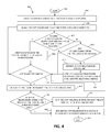
Turning now to FIG. 4, FIG. 4 is a flowchart illustrating an exemplary method 400 for switching between mirrored volumes in a computing environment in which aspects of the present invention may be realized. The method 400 begins (step 402) by creating a copy relation identification (ID) (e.g., a unique name) for a peer-to-peer remote copy (PPRC) that includes a volume identification (ID) of a primary mirror and a unique ID of the mirror relationship (step 404). Assign the copy relation ID to a primary PPRC and a secondary PPRC (step 406). The copy relation ID is stored in metadata on both the primary PPRC and the secondary PPRC, and includes a serial number of the primary PPRC and a time stamp of the creation of a relationship between the primary PPRC and the secondary PPRC. The method 400 then determines if a volume is added to the mirrored relationship and/or changes from a simplex type volume to the peer-to-peer remote copy (PPRC) volume (step 407). If yes, the copy relation ID is created for and/or moved to the added volume (step 408). If no, the method 400 determines if any volume changes from the PPRC volume back to the simplex type volume (step 410). If the volume changes from the PPRC volume back to the simplex type volume, the copy relation ID is retained by the volume thereby a host access is not interrupted (step 412). If no, the method 400 may jump to step 416 and determine if a hyperswap is performed (step 416). After step 412, the method 400 may then retain the association between the volume and the copy relation ID until a new PPRC relation is created for the volume (step 414). From either step 406, 410, and/or 414, the method 400 may the determine if a hyperswap is performed (step 416). If yes, the method switches the peer-to-peer remote copy (PPRC) from being a primary PPRC to being a secondary PPRC (step 418). If no hyperswap is performed, the method 400 may move to step 424 and returns the copy relation ID to a host (step 424). At step 418, the secondary PPRC becomes a new primary PPRC and retains the copy relation ID created for the relationship between the primary PPRC and the secondary PPRC. The method 400 then determines if the new primary PPRC is established/re-established with a volume that becomes a new secondary PPRC (step 420). If yes, the copy relation ID is copied from the new primary PPRC to the new secondary PPRC (step 422). From step 404, upon assigning the copy relation ID to a volume, the method 400 returns the copy relation ID to a host as a vendor-specification designation descriptor within a device identification vital product data (VPD) page (step 424). The method 400 ends (step 426).
In one embodiment, as further described below in FIG. 5, in an Advanced IBM Unix (AIX) Multiple Path I/O (MPIO), along with an AIX Path Control Module (PCM), uses the “CopyRelationID” to identify multiple LUN's that are configured as a single device in a storage area network (SAN) replication Device. These LUN's configured as a SAN replication device are identified as a single disk instance on AIX. The state of the SAN replication device is determined by the PPRC state on the storage system. The state indicates whether a swap can be done from one LUN to another LUN configured as part of the SAN replication device. If a timeout occurs on a path, the SAN replication device state indicates it can be swapped and the retries on that path have exceeded a swap time threshold, the PCM will swap (e.g., failover) to another LUN configured as part of the SAN replication device. After the swap, the PCM will redirect the I/O to the SAN replication device on an alternate path, as it would redirect I/O to an alternate path for a single LUN in MPIO. Thus, the present invention allows multi-pathing drivers to swap I/O between mirrored LUNs using the same method that redirects I/O to an alternate path on the same LUN.
FIG. 5 is a flowchart illustrating an alternative exemplary method 500 for switching between mirrored volumes in a computing environment in which aspects of the present invention may be realized. The method 500 begins (step 502) by determining a state of one of the mirrored volumes by a state of a peer-to-peer remote copy (PPRC) (step 504). The method 500 indicates by the state of the peer-to-peer remote copy (PPRC) whether a switch may be performed from one of the mirrored volumes to an alternative one of the mirrored volumes (step 506). The method 500 switches (swaps) from one of the mirrored volumes to an alternative one of the mirrored volumes upon either a time out or a failure of one of the mirrored volumes (step 508). Next, the method 500 may retry a path for the mirrored volume after the timeout has exceeded a threshold (step 510). After performing the switching, the method 500 may redirect the I/O to a host via an alternative path from the one of the mirrored volumes to the alternative one of the mirrored volumes via a multi-path device drivers (step 512). The method 500 ends (step 514).
As will be appreciated by one skilled in the art, aspects of the present invention may be embodied as a system, method or computer program product. Accordingly, aspects of the present invention may take the form of an entirely hardware embodiment, an entirely software embodiment (including firmware, resident software, micro-code, etc.) or an embodiment combining software and hardware aspects that may all generally be referred to herein as a “circuit,” “module” or “system.” Furthermore, aspects of the present invention may take the form of a computer program product embodied in one or more computer readable medium(s) having computer readable program code embodied thereon.
Any combination of one or more computer readable medium(s) may be utilized. The computer readable medium may be a computer readable signal medium or a computer readable storage medium. A computer readable storage medium may be, for example, but not limited to, an electronic, magnetic, optical, electromagnetic, infrared, or semiconductor system, apparatus, or device, or any suitable combination of the foregoing. More specific examples (a non-exhaustive list) of the computer readable storage medium would include the following: an electrical connection having one or more wires, a portable computer diskette, a hard disk, a random access memory (RAM), a read-only memory (ROM), an erasable programmable read-only memory (EPROM or Flash memory), an optical fiber, a portable compact disc read-only memory (CD-ROM), an optical storage device, a magnetic storage device, or any suitable combination of the foregoing. In the context of this document, a computer readable storage medium may be any tangible medium that may contain, or store a program for use by or in connection with an instruction execution system, apparatus, or device.
Program code embodied on a computer readable medium may be transmitted using any appropriate medium, including but not limited to wireless, wired, optical fiber cable, RF, etc., or any suitable combination of the foregoing. Computer program code for carrying out operations for aspects of the present invention may be written in any combination of one or more programming languages, including an object oriented programming language such as Java, Smalltalk, C++ or the like and conventional procedural programming languages, such as the “C” programming language or similar programming languages. The program code may execute entirely on the user's computer, partly on the user's computer, as a stand-alone software package, partly on the user's computer and partly on a remote computer or entirely on the remote computer or server. In the latter scenario, the remote computer may be connected to the user's computer through any type of network, including a local area network (LAN) or a wide area network (WAN), or the connection may be made to an external computer (for example, through the Internet using an Internet Service Provider).
Aspects of the present invention have been described above with reference to flowchart illustrations and/or block diagrams of methods, apparatus (systems) and computer program products according to embodiments of the invention. It will be understood that each block of the flowchart illustrations and/or block diagrams, and combinations of blocks in the flowchart illustrations and/or block diagrams, may be implemented by computer program instructions. These computer program instructions may be provided to a processor of a general purpose computer, special purpose computer, or other programmable data processing apparatus to produce a machine, such that the instructions, which execute via the processor of the computer or other programmable data processing apparatus, create means for implementing the functions/acts specified in the flowchart and/or block diagram block or blocks.
These computer program instructions may also be stored in a computer readable medium that may direct a computer, other programmable data processing apparatus, or other devices to function in a particular manner, such that the instructions stored in the computer readable medium produce an article of manufacture including instructions which implement the function/act specified in the flowchart and/or block diagram block or blocks. The computer program instructions may also be loaded onto a computer, other programmable data processing apparatus, or other devices to cause a series of operational steps to be performed on the computer, other programmable apparatus or other devices to produce a computer implemented process such that the instructions which execute on the computer or other programmable apparatus provide processes for implementing the functions/acts specified in the flowchart and/or block diagram block or blocks.
The flowchart and block diagrams in the above figures illustrate the architecture, functionality, and operation of possible implementations of systems, methods and computer program products according to various embodiments of the present invention. In this regard, each block in the flowchart or block diagrams may represent a module, segment, or portion of code, which comprises one or more executable instructions for implementing the specified logical function(s). It should also be noted that, in some alternative implementations, the functions noted in the block may occur out of the order noted in the figures. For example, two blocks shown in succession may, in fact, be executed substantially concurrently, or the blocks may sometimes be executed in the reverse order, depending upon the functionality involved. It will also be noted that each block of the block diagrams and/or flowchart illustration, and combinations of blocks in the block diagrams and/or flowchart illustration, may be implemented by special purpose hardware-based systems that perform the specified functions or acts, or combinations of special purpose hardware and computer instructions.

Claims (24)

What is claimed is:
1. A method for switching between mirrored volumes by using a processor device in a computing environment, the method, executed by the processor device, comprising:
creating, by the processor device, a copy relation identification (ID) created for both mirrored volumes for using the copy relation ID in conjunction with a multi-path device driver for switching input/output (I/O) for applications between a first path to a second path between the mirrored volumes, wherein the copy relation ID includes a primary volume ID of the primary mirror, a secondary volume ID for a second mirror, and a unique ID of a relationship between the mirrored volumes, the copy relation ID is a common identifier for both the mirrored volumes that is unique among all volumes; and
using the copy relation ID for identifying volumes capable of hyperswaping and switching I/O for applications between the first path to the second path between the mirrored volumes.
2. The method of claim 1, further including returning the copy relation ID to a host via a vendor-specification designation descriptor in the event of a failover.
3. The method of claim 1, further including moving the copy relation ID between one of each of the mirrored volumes and a volume that was later added to the mirrored volumes, wherein the copy relation ID identifies the mirrored volumes capable of performing a hyperswap.
4. The method of claim 1, further including, upon creating a peer-to-peer remote copy (PPRC), assigning the copy relation ID to a primary PPRC and a secondary PPRC, wherein the copy relation ID is stored in metadata on both the primary PPRC and the secondary PPRC, includes a serial number of the primary PPRC and a time stamp of the creation of a relationship between the primary PPRC and the secondary PPRC.
5. The method of claim 1, further including:
creating the copy relation ID in a volume when the volume changes from a simplex type volume to a peer-to-peer remote copy (PPRC) volume, wherein if the volume changes back to the simplex type volume the copy relation ID retained and thereby a host access is not interrupted, and
retaining an association between the volume and the copy relation ID until a new PPRC relation is created for the volume.
6. The method of claim 5, further including:
switching the PPRC from being a primary PPRC to being a secondary PPRC if a hyperswap is performed, wherein the secondary PPRC becomes a new primary PPRC,
retaining the copy relation ID created for the relationship between the primary PPRC and the secondary PPRC, and
if the new primary PPRC is re-established with a volume that becomes a new secondary PPRC, copying the copy relation ID from the new primary PPRC to the new secondary PPRC.
7. The method of claim 6, further including, upon assigning the copy relation ID to a volume, returning to a host as a vendor-specification designation descriptor within a device identification vital product data (VPD) page.
8. The method of claim 1, further including:
determining a state of one of the mirrored volumes by a state of a peer-to-peer remote copy (PPRC),
indicating by the state of the PPRC whether a switch may be performed from one of the mirrored volumes to an alternative one of the mirrored volumes,
switching from the one of the mirrored volumes to the alternative one of the mirrored volumes upon one of a time out and a failure of the one of the mirrored volumes,
retrying a path for the one of the mirrored volume after the timeout has exceeded a threshold, and
after performing the switching, redirecting the I/O to a host via an alternative path from the one of the mirrored volumes to the alternative one of the mirrored volumes via the multi-path device driver.
9. A system for switching between mirrored volumes in a computing environment, the system comprising:
a multi-path device driver,
a processor device, in communication with the multi-path device driver, operable in the computing storage environment, wherein the processor device:
creates a copy relation identification (ID) created for both mirrored volumes for using the copy relation ID in conjunction with the multi-path device driver for switching input/output (I/O) for applications between a first path to a second path between the mirrored volumes, wherein the copy relation ID includes a primary volume ID of the primary mirror, a secondary volume ID of the second minor, and a unique ID of a relationship between the mirrored volumes, the copy relation ID is a common identifier for both of the mirrored volumes that is unique among all volumes; and
using the copy relation ID for identifying volumes capable of hyperswaping and switching I/O for applications between the first path to the second path between the mirrored volumes.
10. The system of claim 9, wherein the processor device, upon assigning the copy relation ID to a volume, returns the copy relation ID to a host via a vendor-specification designation descriptor in the event of a failover.
11. The system of claim 9, wherein the processor device moves the copy relation ID between one of each of the mirrored volumes and a volume that was later added to the mirrored volumes, wherein the copy relation ID identifies the mirrored volumes capable of performing a hyperswap.
12. The system of claim 9, wherein the processor device, upon creating a peer-to-peer remote copy (PPRC), assigns the copy relation ID to a primary PPRC and a secondary PPRC, wherein the copy relation ID is stored in metadata on both the primary PPRC and the secondary PPRC, includes a serial number of the primary PPRC and a time stamp of the creation of a relationship between the primary PPRC and the secondary PPRC.
13. The system of claim 9, wherein the processor device:
creates the copy relation ID in a volume when the volume changes from a simplex type volume to a peer-to-peer remote copy (PPRC) volume, wherein if the volume changes back to the simplex type volume the copy relation ID retained and thereby a host access is not interrupted, and
retains an association between the volume and the copy relation ID until a new PPRC relation is created for the volume.
14. The system of claim 13, wherein the processor device:
switches the PPRC from being a primary PPRC to being a secondary PPRC if a hyperswap is performed, wherein the secondary PPRC becomes a new primary PPRC,
retains the copy relation ID created for the relationship between the primary PPRC and the secondary PPRC, and
if the new primary PPRC is re-established with a volume that becomes a new secondary PPRC, copies the copy relation ID from the new primary PPRC to the new secondary PPRC.
15. The system of claim 14, wherein the processor device assigns the copy relation ID to a volume and returns to a host as a vendor-specification designation descriptor within a device identification vital product data (VPD) page.
16. The system of claim 9, wherein the processor device:
determines a state of one of the mirrored volumes by a state of a peer-to-peer remote copy (PPRC),
indicates by the state of the PPRC whether a switch may be performed from one of the mirrored volumes to an alternative one of the mirrored volumes,
switches from the one of the mirrored volumes to the alternative one of the mirrored volumes upon one of a time out and a failure of the one of the mirrored volumes,
retries a path for the one of the mirrored volume after the timeout has exceeded a threshold, and
after performing the switching, redirects the I/O to a host via an alternative path from the one of the mirrored volumes to the alternative one of the mirrored volumes via the multi-path device driver.
17. A computer program product for switching between mirrored volumes by a processor device, the computer program product comprising a non-transitory computer-readable storage medium having computer-readable program code portions stored therein, the computer-readable program code portions comprising:
a first executable portion that creates a copy relation identification (ID) created for both mirrored volumes for using the copy relation ID in conjunction with a multi-path device driver for switching input-output (I/O) for applications between a first path to a second path between the mirrored volumes, wherein the copy relation ID includes a primary volume ID of the primary mirror, a secondary volume ID of the second minor, and a unique ID of a relationship between mirrored volumes, the copy relation ID is a common identifier for both of the mirrored volumes that unique to all volumes; and
using the copy relation ID for identifying volumes capable of hyperswaping and switching I/O for applications between the first path to the second path between the mirrored volumes.
18. The computer program product of claim 17, further including a second executable portion that, upon an assignment of the copy relation ID to a volume, returns the copy relation ID to a host via a vendor-specification designation descriptor in the event of a failover.
19. The computer program product of claim 17, further including a second executable portion that moves the copy relation ID between one of each of the mirrored volumes and a volume that was later added to the mirrored volumes, wherein the copy relation ID identifies the mirrored volumes capable of performing a hyperswap.
20. The computer program product of claim 17, further including a second executable portion that, upon creating a peer-to-peer remote copy (PPRC), assigns the copy relation ID to a primary PPRC and a secondary PPRC, wherein the copy relation ID is stored in metadata on both the primary PPRC and the secondary PPRC, includes a serial number of the primary PPRC and a time stamp of the creation of a relationship between the primary PPRC and the secondary PPRC.
21. The computer program product of claim 17, further including a second executable portion that:
creates the copy relation ID in a volume when the volume changes from a simplex type volume to a peer-to-peer remote copy (PPRC) volume, wherein if the volume changes back to the simplex type volume the copy relation ID retained and thereby a host access is not interrupted, and
retains an association between the volume and the copy relation ID until a new PPRC relation is created for the volume.
22. The computer program product of claim 21, further including a third executable portion that:
switches the PPRC volume from being a primary PPRC to being a secondary PPRC if a hyperswap is performed, wherein the secondary PPRC becomes a new primary PPRC,
retains the copy relation ID created for the relationship between the primary PPRC and the secondary PPRC, and
if the new primary PPRC is re-established with a volume that becomes a new secondary PPRC, copies the copy relation ID from the new primary PPRC to the new secondary PPRC.
23. The computer program product of claim 22, further including a fourth executable portion that assigns the copy relation ID to a volume and returns to a host as a vendor-specification designation descriptor within a device identification vital product data (VPD) page.
24. The computer program product of claim 17, further including a second executable portion that:
determines a state of one of the mirrored volumes by a state of a peer-to-peer remote copy (PPRC),
indicates by the state of the PPRC whether a switch may be performed from one of the mirrored volumes to an alternative one of the mirrored volumes,
switches from the one of the mirrored volumes to the alternative one of the mirrored volumes upon one of a time out and a failure of the one of the mirrored volumes,
retries a path for the one of the mirrored volume after the timeout has exceeded a threshold, and
after performing the switching, redirects the I/O to a host via an alternative path from the one of the mirrored volumes to the alternative one of the mirrored volumes via the multi-path device driver.
US13/663,221 2012-10-29 2012-10-29 Switching between mirrored volumes Expired - Fee Related US9098466B2 (en)

Priority Applications (2)

Application Number Priority Date Filing Date Title
US13/663,221 US9098466B2 (en) 2012-10-29 2012-10-29 Switching between mirrored volumes
CN201310518365.9A CN103793271B (en) 2012-10-29 2013-10-29 Methods and systems for switching between mirrored volumes

Applications Claiming Priority (1)

Application Number Priority Date Filing Date Title
US13/663,221 US9098466B2 (en) 2012-10-29 2012-10-29 Switching between mirrored volumes

Publications (2)

Publication Number Publication Date
US20140122816A1 US20140122816A1 (en) 2014-05-01
US9098466B2 true US9098466B2 (en) 2015-08-04

Family

ID=50548557

Family Applications (1)

Application Number Title Priority Date Filing Date
US13/663,221 Expired - Fee Related US9098466B2 (en) 2012-10-29 2012-10-29 Switching between mirrored volumes

Country Status (2)

Country Link
US (1) US9098466B2 (en)
CN (1) CN103793271B (en)

Cited By (4)

* Cited by examiner, † Cited by third party
Publication number Priority date Publication date Assignee Title
US20150081990A1 (en) * 2011-04-29 2015-03-19 Comcast Cable Communications, Llc Intelligent Partitioning of External Memory Devices
US10013188B2 (en) * 2014-12-17 2018-07-03 Fujitsu Limited Storage control device and method of copying data in failover in storage cluster
US10439878B1 (en) * 2018-05-31 2019-10-08 EMC IP Holding Company LLC Process-based load balancing and failover policy implementation in storage multi-path layer of host device
US20220129494A1 (en) * 2020-10-22 2022-04-28 EMC IP Holding Company LLC Block-level classification of unstructured data

Families Citing this family (15)

* Cited by examiner, † Cited by third party
Publication number Priority date Publication date Assignee Title
US9342249B2 (en) * 2013-01-02 2016-05-17 International Business Machines Corporation Controlling partner partitions in a clustered storage system
JP6201580B2 (en) * 2013-09-27 2017-09-27 富士通株式会社 Storage control device, storage control method, and storage control program
US9645872B1 (en) * 2015-03-27 2017-05-09 EMC IP Holding Company LLC Method to use multipath to reduce IO error handle duration
US9645636B2 (en) 2015-05-06 2017-05-09 Vmware, Inc. Centralized power management with partial suspend mode for distributed storage systems
US9665163B2 (en) * 2015-05-06 2017-05-30 Vmware, Inc. Distributed power management with partial suspend mode for distributed storage systems
US9898214B2 (en) 2015-09-29 2018-02-20 International Business Machines Corporation Storage site selection in a multi-target environment using weights
US10079883B2 (en) * 2015-12-03 2018-09-18 International Business Machines Corporation Primary device selection at operating system initialization
CN107885622B (en) * 2016-09-30 2021-03-09 伊姆西Ip控股有限责任公司 Handling Virtual Data Mover (VDM) failover conditions
CN107590032A (en) * 2017-09-06 2018-01-16 郑州云海信息技术有限公司 The method and storage cluster system of storage cluster failure transfer
CN108667892A (en) * 2018-03-07 2018-10-16 长沙开雅电子科技有限公司 A kind of dual-active memory system data volume management method
CN109144418A (en) * 2018-08-16 2019-01-04 郑州云海信息技术有限公司 A kind of method of data synchronization and device
US11048430B2 (en) * 2019-04-12 2021-06-29 Netapp, Inc. Object store mirroring where during resync of two storage bucket, objects are transmitted to each of the two storage bucket
CN110704334B (en) * 2019-09-25 2021-10-15 苏州浪潮智能科技有限公司 Method, system and equipment for important product data management
US11277335B2 (en) * 2019-12-26 2022-03-15 EMC IP Holding Company LLC Host device with path selection modification responsive to mismatch in initiator-target negotiated rates
CN113625944B (en) * 2021-06-25 2024-02-02 济南浪潮数据技术有限公司 Disaster recovery method and system based on multipath and remote replication technology

Citations (20)

* Cited by examiner, † Cited by third party
Publication number Priority date Publication date Assignee Title
US5790775A (en) 1995-10-23 1998-08-04 Digital Equipment Corporation Host transparent storage controller failover/failback of SCSI targets and associated units
US20020133512A1 (en) * 2001-03-14 2002-09-19 Storage Technololgy Corporation System and method for synchronizing a data copy using an accumulation remote copy trio consistency group
US6499112B1 (en) * 2000-03-28 2002-12-24 Storage Technology Corporation Automatic stand alone recovery for peer to peer remote copy (PPRC) operations
US20030065780A1 (en) 2001-06-28 2003-04-03 Maurer Charles F. Data storage system having data restore by swapping logical units
US6643795B1 (en) 2000-03-30 2003-11-04 Hewlett-Packard Development Company, L.P. Controller-based bi-directional remote copy system with storage site failover capability
US6691245B1 (en) * 2000-10-10 2004-02-10 Lsi Logic Corporation Data storage with host-initiated synchronization and fail-over of remote mirror
US20040064639A1 (en) * 2000-03-30 2004-04-01 Sicola Stephen J. Controller-based remote copy system with logical unit grouping
US6732104B1 (en) * 2001-06-06 2004-05-04 Lsi Logic Corporatioin Uniform routing of storage access requests through redundant array controllers
US6757753B1 (en) * 2001-06-06 2004-06-29 Lsi Logic Corporation Uniform routing of storage access requests through redundant array controllers
US20060031594A1 (en) * 2004-08-03 2006-02-09 Hitachi, Ltd. Failover and data migration using data replication
US20070006023A1 (en) * 2002-05-07 2007-01-04 Hitachi, Ltd. System and method of volume health checking and recovery
US20070300013A1 (en) * 2006-06-21 2007-12-27 Manabu Kitamura Storage system having transaction monitoring capability
US20080126857A1 (en) * 2006-08-14 2008-05-29 Robert Beverley Basham Preemptive Data Protection for Copy Services in Storage Systems and Applications
US20090235110A1 (en) * 2008-03-17 2009-09-17 Fujitsu Limited Input/output control method, information processing apparatus, computer readable recording medium
US20100049823A1 (en) * 2008-08-21 2010-02-25 Kiyokazu Saigo Initial copyless remote copy
US7877628B2 (en) 2006-06-08 2011-01-25 International Business Machines Corporation Mirroring data between primary and secondary sites
US7895395B2 (en) 2007-04-24 2011-02-22 Hitachi, Ltd. Managing logical volumes in a storage system with remote copy
US8060710B1 (en) 2007-12-12 2011-11-15 Emc Corporation Non-disruptive migration using device identity spoofing and passive/active ORS pull sessions
US20120137096A1 (en) 2006-04-18 2012-05-31 Nobuhiro Maki Dual writing device and its control method
US20120278572A1 (en) * 2011-04-27 2012-11-01 International Business Machines Corporation Online volume migration using multi-path input / output masquerading

Family Cites Families (1)

* Cited by examiner, † Cited by third party
Publication number Priority date Publication date Assignee Title
JP5057366B2 (en) * 2006-10-30 2012-10-24 株式会社日立製作所 Information system and information system data transfer method

Patent Citations (22)

* Cited by examiner, † Cited by third party
Publication number Priority date Publication date Assignee Title
US5790775A (en) 1995-10-23 1998-08-04 Digital Equipment Corporation Host transparent storage controller failover/failback of SCSI targets and associated units
US6499112B1 (en) * 2000-03-28 2002-12-24 Storage Technology Corporation Automatic stand alone recovery for peer to peer remote copy (PPRC) operations
US6643795B1 (en) 2000-03-30 2003-11-04 Hewlett-Packard Development Company, L.P. Controller-based bi-directional remote copy system with storage site failover capability
US20040064639A1 (en) * 2000-03-30 2004-04-01 Sicola Stephen J. Controller-based remote copy system with logical unit grouping
US6691245B1 (en) * 2000-10-10 2004-02-10 Lsi Logic Corporation Data storage with host-initiated synchronization and fail-over of remote mirror
US20020133512A1 (en) * 2001-03-14 2002-09-19 Storage Technololgy Corporation System and method for synchronizing a data copy using an accumulation remote copy trio consistency group
US6732104B1 (en) * 2001-06-06 2004-05-04 Lsi Logic Corporatioin Uniform routing of storage access requests through redundant array controllers
US6757753B1 (en) * 2001-06-06 2004-06-29 Lsi Logic Corporation Uniform routing of storage access requests through redundant array controllers
US20030065780A1 (en) 2001-06-28 2003-04-03 Maurer Charles F. Data storage system having data restore by swapping logical units
US20070006023A1 (en) * 2002-05-07 2007-01-04 Hitachi, Ltd. System and method of volume health checking and recovery
US7058731B2 (en) * 2004-08-03 2006-06-06 Hitachi, Ltd. Failover and data migration using data replication
US20060031594A1 (en) * 2004-08-03 2006-02-09 Hitachi, Ltd. Failover and data migration using data replication
US20120137096A1 (en) 2006-04-18 2012-05-31 Nobuhiro Maki Dual writing device and its control method
US7877628B2 (en) 2006-06-08 2011-01-25 International Business Machines Corporation Mirroring data between primary and secondary sites
US20070300013A1 (en) * 2006-06-21 2007-12-27 Manabu Kitamura Storage system having transaction monitoring capability
US20080126857A1 (en) * 2006-08-14 2008-05-29 Robert Beverley Basham Preemptive Data Protection for Copy Services in Storage Systems and Applications
US7676702B2 (en) * 2006-08-14 2010-03-09 International Business Machines Corporation Preemptive data protection for copy services in storage systems and applications
US7895395B2 (en) 2007-04-24 2011-02-22 Hitachi, Ltd. Managing logical volumes in a storage system with remote copy
US8060710B1 (en) 2007-12-12 2011-11-15 Emc Corporation Non-disruptive migration using device identity spoofing and passive/active ORS pull sessions
US20090235110A1 (en) * 2008-03-17 2009-09-17 Fujitsu Limited Input/output control method, information processing apparatus, computer readable recording medium
US20100049823A1 (en) * 2008-08-21 2010-02-25 Kiyokazu Saigo Initial copyless remote copy
US20120278572A1 (en) * 2011-04-27 2012-11-01 International Business Machines Corporation Online volume migration using multi-path input / output masquerading

Cited By (6)

* Cited by examiner, † Cited by third party
Publication number Priority date Publication date Assignee Title
US20150081990A1 (en) * 2011-04-29 2015-03-19 Comcast Cable Communications, Llc Intelligent Partitioning of External Memory Devices
US10565139B2 (en) * 2011-04-29 2020-02-18 Comcast Cable Communications, Llc Intelligent partitioning of external memory devices
US10013188B2 (en) * 2014-12-17 2018-07-03 Fujitsu Limited Storage control device and method of copying data in failover in storage cluster
US10439878B1 (en) * 2018-05-31 2019-10-08 EMC IP Holding Company LLC Process-based load balancing and failover policy implementation in storage multi-path layer of host device
US20220129494A1 (en) * 2020-10-22 2022-04-28 EMC IP Holding Company LLC Block-level classification of unstructured data
US11816139B2 (en) * 2020-10-22 2023-11-14 EMC IP Holding Company LLC Block-level classification of unstructured data

Also Published As

Publication number Publication date
US20140122816A1 (en) 2014-05-01
CN103793271A (en) 2014-05-14
CN103793271B (en) 2017-04-12

Similar Documents

Publication Publication Date Title
US9098466B2 (en) Switching between mirrored volumes
US10606715B2 (en) Efficient high availability for a SCSI target over a fibre channel
US10963289B2 (en) Storage virtual machine relocation
US11128573B2 (en) Load balancing for IP failover
US9229645B2 (en) Storage management method and storage system in virtual volume having data arranged astride storage devices
US9122653B2 (en) Migrating virtual machines across sites
US9658798B2 (en) Grouping of tracks for copy source to target destage on global mirror secondary
US6598174B1 (en) Method and apparatus for storage unit replacement in non-redundant array
US9009724B2 (en) Load balancing data access in virtualized storage nodes
US9678686B2 (en) Managing sequentiality of tracks for asynchronous PPRC tracks on secondary
US6571354B1 (en) Method and apparatus for storage unit replacement according to array priority
US7870105B2 (en) Methods and apparatus for deduplication in storage system
US8010485B1 (en) Background movement of data between nodes in a storage cluster
US20190310925A1 (en) Information processing system and path management method
US20150324126A1 (en) Storage system with virtual volume having data arranged astride storage devices, and volume management method
US9262087B2 (en) Non-disruptive configuration of a virtualization controller in a data storage system
US9823955B2 (en) Storage system which is capable of processing file access requests and block access requests, and which can manage failures in A and storage system failure management method having a cluster configuration
JP2008112399A (en) Storage virtualization switch and computer system
US20170220249A1 (en) Systems and Methods to Maintain Consistent High Availability and Performance in Storage Area Networks
US7886186B2 (en) Storage system and management method for the same
JP2024049171A (en) Unified storage and method for controlling the same
JP2022124054A (en) Storage system, storage device, and storage device management method

Legal Events

Date Code Title Description
AS Assignment

Owner name: INTERNATIONAL BUSINESS MACHINES CORPORATION, NEW Y

Free format text: ASSIGNMENT OF ASSIGNORS INTEREST;ASSIGNORS:BARNES, JEFFREY M.;DOMROW, GARY S.;HAM, NICHOLAS S.;AND OTHERS;SIGNING DATES FROM 20121017 TO 20121025;REEL/FRAME:029206/0942

STCF Information on status: patent grant

Free format text: PATENTED CASE

MAFP Maintenance fee payment

Free format text: PAYMENT OF MAINTENANCE FEE, 4TH YEAR, LARGE ENTITY (ORIGINAL EVENT CODE: M1551); ENTITY STATUS OF PATENT OWNER: LARGE ENTITY

Year of fee payment: 4

FEPP Fee payment procedure

Free format text: MAINTENANCE FEE REMINDER MAILED (ORIGINAL EVENT CODE: REM.); ENTITY STATUS OF PATENT OWNER: LARGE ENTITY

LAPS Lapse for failure to pay maintenance fees

Free format text: PATENT EXPIRED FOR FAILURE TO PAY MAINTENANCE FEES (ORIGINAL EVENT CODE: EXP.); ENTITY STATUS OF PATENT OWNER: LARGE ENTITY

STCH Information on status: patent discontinuation

Free format text: PATENT EXPIRED DUE TO NONPAYMENT OF MAINTENANCE FEES UNDER 37 CFR 1.362

FP Lapsed due to failure to pay maintenance fee

Effective date: 20230804