US9014006B2 - Adaptive routing using inter-switch notifications - Google Patents
Adaptive routing using inter-switch notifications Download PDFInfo
- Publication number
- US9014006B2 US9014006B2 US13/754,921 US201313754921A US9014006B2 US 9014006 B2 US9014006 B2 US 9014006B2 US 201313754921 A US201313754921 A US 201313754921A US 9014006 B2 US9014006 B2 US 9014006B2
- Authority
- US
- United States
- Prior art keywords
- notification
- network
- switch
- route
- switches
- Prior art date
- Legal status (The legal status is an assumption and is not a legal conclusion. Google has not performed a legal analysis and makes no representation as to the accuracy of the status listed.)
- Active, expires
Links
Images


Classifications
-
- H—ELECTRICITY
- H04—ELECTRIC COMMUNICATION TECHNIQUE
- H04L—TRANSMISSION OF DIGITAL INFORMATION, e.g. TELEGRAPHIC COMMUNICATION
- H04L47/00—Traffic control in data switching networks
- H04L47/10—Flow control; Congestion control
- H04L47/12—Avoiding congestion; Recovering from congestion
- H04L47/122—Avoiding congestion; Recovering from congestion by diverting traffic away from congested entities
Definitions
- the present invention relates generally to communication networks, and particularly to methods and systems for adaptive routing.
- Adaptive Routing Various techniques for routing packets through communication networks are known in the art. Some known techniques select routing paths for packets based on the network state, e.g., traffic load or congestion. Such techniques are sometimes referred to as Adaptive Routing. AR techniques are described, for example, by Kim et al., in “Adaptive Routing in High-Radix Clos Network,” Proceedings of the 2006 ACM/IEEE Conference on Supercomputing (SC2006), Tampa, Fla., November 2006, which is incorporated herein by reference.
- a first packet which belongs to a given packet flow, is routed over a first routing path through a communication network.
- a second packet which follows the first packet in the given packet flow, is routed using a time-bounded Adaptive Routing (AR) mode, by evaluating a time gap between the first and second packets, routing the second packet over the first routing path if the time gap does not exceed a predefined threshold, and, if the time gap exceeds the predefined threshold, selecting a second routing path through the communication network that is potentially different from the first routing path, and routing the second packet over the second routing path.
- AR Adaptive Routing
- An embodiment of the present invention that is described herein provides a method including receiving, in a network switch of a communication network, communication traffic that originates from a source node and arrives over a route through the communication network traversing one or more preceding network switches, for forwarding to a destination node.
- a notification is sent to the preceding network switches. The notification is to be consumed by the preceding network switches and requests the preceding network switches to modify the route so as not to traverse the network switch.
- detecting the compromised ability includes detecting one of a congestion on a network link leaving the network switch en-route to the destination node, a failure in the network link, and a head-of-line time-out at an input to the network link.
- sending the notification includes forwarding the notification in accordance with a forwarding rule that depends on a topology of the communication network.
- detecting the compromised ability includes identifying the compromised ability with respect to a packet having a source address and a destination address, and sending the notification includes substituting the source address of the packet to serve as the destination address of the notification, and substituting the destination address of the packet to serve as the source address of the notification.
- sending the notification includes indicating a cause of the compromised ability in the notification.
- the method includes receiving the notification in a preceding network switch, and modifying the route between the preceding network switch and the destination node in response to the notification.
- the method may include evaluating in the preceding network switch a rule, which ensures that only one of the preceding network switches modifies the route, and modifying the route only when the rule is met.
- the method when the rule is not met, the method includes forwarding the notification to another of the preceding switches. Forwarding the notification may include sending the notification using multicast. In another embodiment, forwarding the notification includes extracting a source address from the notification, caching an association between the source address and a port over which the notification was received, and, upon receiving a packet from the cached source address over a given port, forwarding the notification over the given port.
- the rule depends on a topology of the communication network.
- the communication network has a Fat-Tree (FT) topology
- evaluating the rule includes comparing a level of the preceding network switch in the FT topology to the level of the network switch that sent the notification.
- receiving the notification includes extracting a source address from the notification, and modifying the route includes re-routing all the packets addressed to the extracted source address regardless of whether they are configured for adaptive routing.
- FT Fat-Tree
- sending the notification includes routing the notification over an alternative route that differs from the route traversed by the communication traffic that caused the notification.
- sending the notification includes including in the notification a signature for checking by the preceding switches.
- sending the notification includes preempting processing of another packet in order to give precedence to the notification.
- receiving the communication traffic includes receiving in the communication traffic an indication of a preceding network switch that could have modified the route, and sending the notification includes addressing the notification to the preceding network switch in accordance with the indication.
- a network switch including multiple ports and switching circuitry.
- the ports are configured to communicate with a communication network.
- the switching circuitry is configured to receive communication traffic that originates from a source node and arrives over a route through the communication network traversing one or more preceding network switches, for forwarding to a destination node, and, in response to detecting a compromised ability to forward the communication traffic to the destination node, sending to the preceding network switches a notification, which is to be consumed by the preceding network switches and requests the preceding network switches to modify the route so as not to traverse the network switch.
- a network switch including multiple ports and switching circuitry.
- the ports are configured to communicate with a communication network.
- the switching circuitry is configured to receive communication traffic that originates from a source node and arrives over a route through the communication network, to forward the traffic to a destination node via a downstream network switch, to receive from the downstream network switch a notification that indicates a compromised ability of the downstream network switch to forward the communication traffic to the destination node, and, in response to the notification, to modify the route so as not to traverse the downstream network switch.
- FIG. 1 is a block diagram that schematically illustrates a communication network that uses Adaptive Routing Notification (ARN), in accordance with an embodiment of the present invention
- FIG. 2 is a flow chart that schematically illustrates a method for communication using ARN, in accordance with an embodiment of the present invention
- FIG. 3 is a block diagram that schematically illustrates communication using ARN in a Torus network, in accordance with an embodiment of the present invention
- FIG. 4 is a block diagram that schematically illustrates communication using ARN in a Fat-Tree (FT) network, in accordance with an embodiment of the present invention.
- FIGS. 5A , 5 B and 6 are flow charts that schematically illustrate methods for ARN forwarding, in accordance with embodiments of the present invention.
- Embodiments of the present invention that are described herein provide improved methods and systems for Adaptive Routing (AR) of packets.
- AR Adaptive Routing
- the embodiments described herein refer mainly to Infiniband® networks, but the disclosed techniques can also be used in other suitable network types.
- a communication network comprises multiple packet switches that are interconnected by network links.
- Multiple nodes e.g., Host Channel Adapters (HCAs)
- HCAs Host Channel Adapters
- HCAs Host Channel Adapters
- a switch along the route may detect an event that compromises its ability to forward the flow over the next link.
- an event is referred to herein as an AR event, and may comprise, for example, link-fault, congestion or head-of-line time-out.
- the detecting switch Upon detecting an AR event, the detecting switch generates a packet referred to as an AR Notification (ARN), and sends the ARN backwards along the route.
- ARN typically indicates the AR event to the preceding switches on the route of the flow, and requests the preceding switches to modify the route so as not to traverse the detecting switch.
- a preceding switch When a preceding switch receives the ARN, it typically checks whether it is in a position to modify the route, and whether the flow in question is permitted to undergo AR. If so, the switch consumes the ARN and modifies the route. Otherwise, the switch forwards the ARN to the previous switch along the route. Typically, only one of the preceding switches should modify the route and consume the ARN, in order to avoid unnecessary blocking of ports.
- the rules that specify how ARN packets are generated, forwarded and consumed depend on the network topology.
- Example rules for Fat-Tree (FT) networks are described herein. The disclosed techniques, however, are applicable to various other network topologies.
- the disclosed techniques provide a highly effective alternative to local AR (rerouting packets to a different output port of the detecting switch) and to global AR (network-wide notification of the AR event and network-wide rerouting).
- the AR event is resolved semi-locally by the switches along the route. Since the response is semi-local, AR events are resolved quickly before they escalate and become significant network bottlenecks.
- the disclosed techniques are distributed and scalable by nature, because they do not involve any central entity (e.g., a Subnet Manager (SM) in an Infiniband subnet), and do not require massive re-routing calculations such as performed, for example, by the spanning tree algorithm of IEEE 802.1Q. Furthermore, the disclosed techniques do not require extensive caching resources in the switches for caching flow information.
- SM Subnet Manager
- FIG. 1 is a block diagram that schematically illustrates a communication network 20 that uses Adaptive Routing Notification (ARN), in accordance with an embodiment of the present invention.
- network 20 operates in accordance with the Infiniband® specifications.
- network 20 may operate in accordance with other suitable communication standards or protocols, such as variants of converged Ethernet as described in the IEEE 802.1Q standard.
- Network 20 provides packet communication for multiple nodes 24 .
- a node may comprise, for example, a Host Channel Adapter (HCA) or other Network Interface Card (NIC) of a computer.
- HCA Host Channel Adapter
- NIC Network Interface Card
- Each flow of packets originates from a certain source node and is addressed to a certain destination node.
- the packets of the flow are forwarded over a route through the network that traverses various switches and network links.
- the links are assumed bidirectional.
- the switches and links belong to a certain Infiniband subnet that is managed by a Subnet Manager (SM). Without loss of generality the SM may be embodied in one of the switches, e.g., in switch 28 A.
- SM Subnet Manager
- the figure shows a simplified example of a source node, a destination node, switches 28 A . . . 28 E and links 32 A . . . 32 G.
- the switches may be interconnected in various topologies.
- An example Fat-Tree (FT) topology is addressed in greater detail further below.
- Each switch 28 comprises multiple ports 36 that are configured to receive and transmit packets, switch fabric 40 that is configured to forward the packets between the ports, and a control unit 44 that controls and configures the various switch elements.
- control units 44 of the switches in network 20 carry out Adaptive Routing (AR) techniques that are described in detail below.
- AR Adaptive Routing
- switch fabric 40 and control unit 44 are referred to jointly as switching circuitry that carries out the methods described herein.
- the network and switch configurations shown in FIG. 1 are example configurations, which are chosen purely for the sake of conceptual clarity. In alternative embodiments, any other suitable network and/or switch configuration can be used. Certain switch elements may be implemented using hardware/firmware, such as using one or more Application-Specific Integrated Circuits (ASICs) or Field-Programmable Gate Arrays (FPGAs). Alternatively, some switch elements may be implemented in software or using a combination of hardware/firmware and software elements.
- ASICs Application-Specific Integrated Circuits
- FPGAs Field-Programmable Gate Arrays
- switch functions such as certain functions of control unit 44
- the software may be downloaded to the processor in electronic form, over a network, for example, or it may, alternatively or additionally, be provided and/or stored on non-transitory tangible media, such as magnetic, optical, or electronic memory.
- the route from a source node to a destination node may at some point become unsuitable or compromised in its ability to transfer packets.
- a scenario of this sort may be due to various events, such as congestion, link fault or head-of-line time-out.
- the disclosed techniques adapt the route of the packets in response to detecting such an event. Any event that triggers a change of route is thus referred to herein as an “AR event.”
- the term “congestion” refers to various scenarios in which the bandwidth of a port or link is insufficient for transferring the traffic volume forwarded over this port or link.
- the term “fault” refers to various scenarios in which a permanent or temporary equipment failure in a link or port prevents the link or port from transferring packets.
- the term “head-of-line time-out” refers to scenarios in which packets are delayed in the queues of a switch by more than a permitted time.
- the description that follows refers to link fault and link congestion for the sake of simplicity. Generally, however, fault or congestion in a link may be caused by the link itself, or by the ports or other switch elements associated with the link.
- an AR event is detected by one of the switches along the route when it attempts to output packets on the designated output port.
- the route defined from the source node to the destination node traverses links 32 A, 32 B, 32 C, 32 D and 32 E.
- the packets along this route are forwarded by switches 28 A, 28 B, 28 C and 28 D.
- switch 28 C detects an AR event on link 32 D when attempting to forward packets over link 32 D to switch 28 D.
- the switch detecting the AR event is referred to as a detecting switch or an identifying switch.
- the switches along the route between the source node and the detecting switch are referred to herein as preceding switches.
- switch 28 is the detecting switch and switches 28 A and 28 B are the preceding switches.
- the detecting switch upon detecting an AR event, the detecting switch generates a notification packet that is referred to as an Adaptive Routing Notification (ARN).
- ARN typically has a unique identifier that distinguishes it from other packet types.
- the detecting switch sends the ARN backwards along the route to the preceding switches.
- the ARN notifies the preceding switches that an AR event has been detected by the detecting switch, and requests them to modify the route so as not to traverse the detecting switch.
- the AR event is detected with regard to a packet or multiple packets of a certain flow, having a certain source address and a destination address.
- the detecting switch generates the ARN with these source and destination addresses reversed.
- the source address is used as the destination address of the ARN, and the destination address is used as the source address of the ARN.
- the ARN typically comprises parameters such as the identity of the detecting switch, the type of AR event (e.g., congestion or link fault), the source and destination address (e.g., Source Local Identifier—SLID and Destination Local Identifier—DLID) of the flow that triggered the AR event, and/or any other suitable parameters.
- the type of AR event e.g., congestion or link fault
- the source and destination address e.g., Source Local Identifier—SLID and Destination Local Identifier—DLID
- the ARN packet is sent backwards along the route to the preceding switches.
- Each preceding switch evaluates whether it can modify the route so as to circumvent the detecting switch. If a preceding switch decides it can modify the route, it does so and consumes the ARN. Otherwise, the preceding switch forwards the ARN to the previous preceding switch along the route.
- FIG. 2 is a flow chart that schematically illustrates the above-described method with reference to the example of FIG. 1 , in accordance with an embodiment of the present invention.
- the method begins with network 20 forwarding packets of a certain flow from the source node to the destination node, at a forwarding step 50 .
- the packets are initially forwarded over links 32 A, 32 B, 32 C, 32 D and 32 E, i.e., via switches 28 A, 28 B, 28 C and 28 D.
- switch 28 C detects an AR event on link 32 D, at a detection step 54 .
- Switch 28 C generates and sends an ARN backwards along the route, at a notification step 58 .
- switch 28 B receives the ARN, but decides it cannot modify the route, and therefore forwards the ARN onwards to switch 28 A.
- Switch 28 A receives the ARN and decides it is able to modify the route.
- the modified route to the destination node passes through link 32 F, switch 28 E, link 32 G, switch 28 D and link 32 E.
- Switch 28 A modifies the route so as not to traverse switch 28 C, at a rerouting step 66 .
- Subsequent traffic is forwarded via the modified route, at a subsequent communication step 70 .
- some flows are defined in as AR-enabled, and other flows are not permitted to undergo AR.
- the AR definition of a flow is typically stored in the switches that process that flow. When a preceding switch receives an ARN, it first checks whether the flow in question is permitted to undergo AR. If not, the switch forwards the ARN without checking whether it can modify the route.
- the preceding switch upon receiving the ARN packet, performs a lookup in its forwarding table on both the destination address and the source address of the ARN. If the source address of the ARN is defined as subject to adaptive routing, then the packet will trigger changing the port number of the corresponding address. Subsequent traffic will thus be forwarded through a different route. If the source address of the ARN is not associated with an address that is subject to adaptive routing, then the preceding switch will continue forwarding the packet normally to the next link.
- the preceding switch upon receiving an ARN having a certain source address (i.e., the DLID of the packet that initiated the ARN), the preceding switch re-routes all the flows addressed to this DLID regardless of whether they are configured in the switch as subject to AR or static (not subject to AR).
- the switch will map both [DLID 7, Tclass 8] and [DLID 7, Tclass 9] to port 11.
- the handling of congestion events differs from the handling of link-fault events.
- the preceding switch modifies the route for all the flows that traverse the failed link. If, on the other hand, the ARN indicates that the AR event is due to congestion, the preceding switch may modify the route for only a subset of these flows, or even a single flow. In the latter case, the preceding switch may select the flows for which to modify the route using any suitable criterion. For example, the preceding switch may reroute the highest-bandwidth flows.
- Congestion AR events typically require fast response, e.g., on the order of microseconds.
- Link-fault AR events can typically tolerate longer latencies, e.g., on the order of ⁇ 50 mSec.
- congestion AR events should typically be processed using hardware or firmware, whereas link-fault AR events may be processed using software.
- the disclosed techniques enable considerably faster response to link-fault AR events, on the order of 1 mSec per switch or SmSec for a series of five switches.
- FIG. 3 is a block diagram that schematically illustrates communication using ARN in a Torus network, in accordance with an embodiment of the present invention.
- the network of FIG. 3 comprises sixteen switches denoted A . . . Q.
- Switch B holds an AR definition for flows having a DLID of switch H. This AR definition defies two routes—One route (denoted 74 A) via the port to switch C, and another route (denoted 74 B) via the port to switch F.
- switch D sends an ARN backwards toward switch A.
- switch B blocks the port to switch C in its AR definition, and thus cause the packets to switch H to go through switch F. Note that the backward path of the ARN may differ from the forward path of the packet that initiated the ARN.
- the rules that govern generation, forwarding and consumption of ARN packets depend on the network topology.
- One popular network topology is Fat-Tree (FT), which is addressed, for example, by Ding et al., in “Level-wise Scheduling Algorithm for Fat Tree Interconnection Networks,” Proceedings of the 2006 ACM/IEEE Conference on Supercomputing (SC 2006), November, 2006, which is incorporated herein by reference.
- FT Fat-Tree
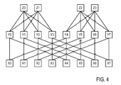
- FIG. 4 is a block diagram that schematically illustrates communication using ARN in a Fat-Tree (FT) network, in accordance with an embodiment of the present invention.
- the network of FIG. 4 comprises a total of twenty switches that are interconnected by network links in a FT configuration.
- Level 0 comprises switches X0 . . . X7
- Level 1 comprises switches Y0 . . . Y7
- Level 2 comprises switches Z0 . . . Z3.
- Clients e.g., HCAs
- L0 L0
- L1 L1
- L2 L2
- Clients are connected only to the switches in L0 (X0 . . . X7).
- Each switch is similar to switches 28 of FIG. 1 above.
- a given switch may forward packets “upwards” to a higher level or “downwards” to a lower level. Except for level 2, each switch has two ports that forward packets upwards to the next higher level. One of these ports is defined as a primary port and the other is defined as a secondary port.
- switch Y5 detects that the link from Y5 to X5 suffers from fault or congestion. Switch Y5 thus generates an ARN packet as explained below.
- the FT configuration shown in FIG. 4 is chosen purely by way of example. In alternative embodiment, any other suitable FT configuration can be used.
- the network may have any desired number of levels, and each switch may have more than two ports that forward packets upwards to the next higher level. Generally, however, the highest-level switches have only ports that forward packets downwards, the switches in the other levels have both upward and downward pointing ports, and only the lowest level switches connect downwards to HCAs/NICs. Paths in the network go upwards and then downwards, and are not permitted to alternate between upwards and downwards directions. Since the HCAs/NICs are connected to the lowest level, all paths start with the upward direction.
- the rules that define how to generate, forward and consume ARN packets are derived from the unique characteristics of the FT network.
- the description that follows first addresses ARN packets triggered by link-fault AR events (referred to herein as “link-fault ARN” for brevity), and then ARN packets triggered by congestion AR events (referred to herein as “congestion ARN”).
- link-fault ARN detected by a switch in a given level should be forwarded to all the switches in the same level, and not to the switches in other levels.
- the forwarding rule in each switch for a link-fault ARN in a FT network is as follows:
- FIGS. 5A and 5B are flow charts that schematically illustrate methods for upward and downward ARN forwarding in a FT network, respectively, in accordance with an embodiment of the present invention.
- the method of FIG. 5A begins with a switch checking whether a received ARN was received from a higher level in the FT, at a higher-level checking step 80 . If yes, the switch does not forward the ARN upwards and the method terminates at a termination step 84 . If the ARN was received from a lower level, the switch selects an upward port and forwards the ARN over the selected port, at an upward forwarding step 88 . As explained above, the upward port may be selected in any suitable way.
- the method of FIG. 5B begins with a switch checking whether a received ARN is to be consumed by the switch, at a consumption checking step 90 . If yes, the switch does not forward the ARN downwards and the method terminates at a termination step 94 . If the ARN is not to be consumed, the switch forwards the ARN over all ports except the one over which the ARN arrived, at a downward forwarding step 98 .
- the ARN packets are given preemption over other packets.
- an ARN may cause suspension of an already-outgoing packet, transmission of the ARN, and then resumption of the outgoing packet.
- the consuming switch is decided based on the level in the tree: If the level of the preceding switch is one below the level of the detecting switch, then the preceding switch consumes the ARN and performs rerouting. Otherwise, the preceding switch forwards the ARN using the forwarding rules above.
- the consuming switch typically looks up the DLID of the ARN, so as to determine the port group over which rerouting may be performed. Within this port group, the switch marks the port over which the ARN was received as not allowed. Note that the look-up should be performed for static ports, as well.
- the switch hardware holds a consume enable and forward enable flag per Receive Port (RP).
- RP Receive Port
- the switch firmware will re-enable the port in the port group, or change back the static port, after a time period on the order of 10 mS for congestion and on the order of 30S for link fault.
- ARNs are forwarded using a forwarding technique that is referred to herein as “hop-by-hop ARN” or “DLID ambush.” This technique is effective in coping with routes that change over time due to AR, without requiring extensive caching of all (source, destination) pairs.
- FIG. 6 is a flow chart that schematically illustrates a method for ARN forwarding using “DLID ambush,” in accordance with an embodiment of the present invention.
- the method begins with a switch receiving an ARN from a given originating DLID over a given Receive Port (RP), at an ARN reception step 100 .
- the switch caches the pair (originating DLID, RP), at a caching step 104 .
- the oldest cache entry is deleted if the cache is full.
- the switch checks whether it should consume the ARN, at a consumption checking step 108 . If the switch is to consume the ARN, the consumption is performed as described above, at a consumption step 112 . Otherwise, the ARN is not forwarded immediately upon receipt. Instead, the switch delays the forwarding until detecting that a new packet is received from an originating DLID that exists in the cache, at a packet checking step 116 . When such a packet arrives, the switch forwards the ARN to the RQ of the received DLID, at a forwarding step 120 . This technique ensures that only one switch in each level will receive the ARN. Note that the ARN may be forwarded over any RP, not necessarily over the original path.
- the switches may use any other suitable rules for processing (e.g., generating, forwarding and/or consuming) ARN packets, derived from the network topology.
- the ARN packet may have different formats.
- the ARN packet format is based on the Infiniband flow control packet format.
- the ARN packet may use unique op-codes to indicate the type of AR event (e.g., link-fault or congestion). Additional fields may comprise, for example, flags that request the switch to force consumption or force forwarding, service level indication for congestion ARNs, indication of the Fat-Tree level of the detecting switch, and/or any other suitable fields.
- Another field may comprise a general signature that can be checked using mask bits by all ARN receive switches.
- the ARN packet format is based on the Local Routing Header (LRH) format.
- the ARN packet has a unique op-code such as 0xFF.
- the Base Transport Header (BTH) fields of the packet may comprise additional flags such as force consumption, force forwarding, indication of the Fat-Tree level of the detecting switch, and/or any other suitable field.
- each packet comprises a header field that indicates the identity (e.g., LID) of the last switch along the packet's route that could have taken a different routing decision with respect to the packet.
- the subsequent switch overwrites the previous content of this field with its own LID.
- the packet carries the LID of the last switch that could have routed the packet through a different port (although it may also maintain one or more LIDs of previous switches that have performed AR).
- the detecting switch When such a packet reaches the detecting switch (the switch that initiates the ARN), the detecting switch extracts the LID of the last switch that could have routed the packet differently from the packet, and sends an ARN addressed specifically to that LID. This process provides a single decision as to which switch should consume the ARN and perform AR, even though reverse paths may differ from forward paths.
- every switch along the packet's route adds its LID to the packet instead of overwriting.
- the detecting switch is provided with the LIDs of all preceding switches that can potentially modify the route.
- the detecting switch can thus choose one of these switches and address the ARN to the chosen switch.
- the latter process can be used, for example, in a Fat-Tree network using level-wise scheduling. Consider, for example, a four-level fat-tree network having levels from 0 (bottom) to 3 (top). Upon detecting a failure when going down to level 1, the ARN will be sent back to level 1. AR may have been performed at levels 0, 1, and 2, so the ARN should go back to the 2 nd LID.
Abstract
Description
-
- Forwarding upwards to higher level:
- If ARN is received from upwards port, do not forward upwards.
- Else: If the primary upward transmit port is functional, forward ARN over this port.
- Else: If the secondary upward transmit port is functional, forward ARN over this port. (Generally, upstream forwarding may be performed over any port and using any policy, including random selection. The use of primary and secondary ports is shown by way of example.)
- Else: Randomly select an upstream port.
- Forwarding downwards to lower level:
- If consuming the ARN, do not forward. (The generating (detecting) switch does not consume the ARN.)
- Else: Forward the ARN using multicast to each port except the port over which the ARN was received. (For the generating (detecting) switch, the detected faulty port is regarded as the port over which the ARN was received.)
- Forwarding upwards to higher level:
-
- If consuming the ARN, do not forward. (The generating (detecting) switch does not consume the ARN.)
- Else: Forward the ARN to the destination address of the ARN packet where the destination address has taken the value of the original source address of the packet that has caused the generation of the ARN. (For the generating (detecting) switch, the detected faulty port is regarded as the port over which the ARN was received.)
Claims (29)
Priority Applications (2)
| Application Number | Priority Date | Filing Date | Title |
|---|---|---|---|
| US13/754,921 US9014006B2 (en) | 2013-01-31 | 2013-01-31 | Adaptive routing using inter-switch notifications |
| US14/662,259 US9634940B2 (en) | 2013-01-31 | 2015-03-19 | Adaptive routing using inter-switch notifications |
Applications Claiming Priority (1)
| Application Number | Priority Date | Filing Date | Title |
|---|---|---|---|
| US13/754,921 US9014006B2 (en) | 2013-01-31 | 2013-01-31 | Adaptive routing using inter-switch notifications |
Related Child Applications (1)
| Application Number | Title | Priority Date | Filing Date |
|---|---|---|---|
| US14/662,259 Continuation-In-Part US9634940B2 (en) | 2013-01-31 | 2015-03-19 | Adaptive routing using inter-switch notifications |
Publications (2)
| Publication Number | Publication Date |
|---|---|
| US20140211631A1 US20140211631A1 (en) | 2014-07-31 |
| US9014006B2 true US9014006B2 (en) | 2015-04-21 |
Family
ID=51222839
Family Applications (1)
| Application Number | Title | Priority Date | Filing Date |
|---|---|---|---|
| US13/754,921 Active 2033-10-25 US9014006B2 (en) | 2013-01-31 | 2013-01-31 | Adaptive routing using inter-switch notifications |
Country Status (1)
| Country | Link |
|---|---|
| US (1) | US9014006B2 (en) |
Cited By (35)
| Publication number | Priority date | Publication date | Assignee | Title |
|---|---|---|---|---|
| US9699095B2 (en) | 2015-05-21 | 2017-07-04 | Mellanox Technologies Tlv Ltd. | Adaptive allocation of headroom in network devices |
| US9699067B2 (en) | 2014-07-22 | 2017-07-04 | Mellanox Technologies, Ltd. | Dragonfly plus: communication over bipartite node groups connected by a mesh network |
| US9729473B2 (en) | 2014-06-23 | 2017-08-08 | Mellanox Technologies, Ltd. | Network high availability using temporary re-routing |
| US9762491B2 (en) | 2015-03-30 | 2017-09-12 | Mellanox Technologies Tlv Ltd. | Dynamic thresholds for congestion control |
| US9806994B2 (en) | 2014-06-24 | 2017-10-31 | Mellanox Technologies, Ltd. | Routing via multiple paths with efficient traffic distribution |
| US9894005B2 (en) | 2015-03-31 | 2018-02-13 | Mellanox Technologies, Ltd. | Adaptive routing controlled by source node |
| US9973435B2 (en) | 2015-12-16 | 2018-05-15 | Mellanox Technologies Tlv Ltd. | Loopback-free adaptive routing |
| US9985910B2 (en) | 2016-06-28 | 2018-05-29 | Mellanox Technologies Tlv Ltd. | Adaptive flow prioritization |
| US10069748B2 (en) | 2015-12-14 | 2018-09-04 | Mellanox Technologies Tlv Ltd. | Congestion estimation for multi-priority traffic |
| US10069701B2 (en) | 2016-01-13 | 2018-09-04 | Mellanox Technologies Tlv Ltd. | Flexible allocation of packet buffers |
| US10084716B2 (en) | 2016-03-20 | 2018-09-25 | Mellanox Technologies Tlv Ltd. | Flexible application of congestion control measures |
| US10178029B2 (en) | 2016-05-11 | 2019-01-08 | Mellanox Technologies Tlv Ltd. | Forwarding of adaptive routing notifications |
| US10200294B2 (en) | 2016-12-22 | 2019-02-05 | Mellanox Technologies Tlv Ltd. | Adaptive routing based on flow-control credits |
| US10205683B2 (en) | 2016-03-28 | 2019-02-12 | Mellanox Technologies Tlv Ltd. | Optimizing buffer allocation for network flow control |
| US10250530B2 (en) | 2016-03-08 | 2019-04-02 | Mellanox Technologies Tlv Ltd. | Flexible buffer allocation in a network switch |
| US10389646B2 (en) | 2017-02-15 | 2019-08-20 | Mellanox Technologies Tlv Ltd. | Evading congestion spreading for victim flows |
| US10387074B2 (en) | 2016-05-23 | 2019-08-20 | Mellanox Technologies Tlv Ltd. | Efficient use of buffer space in a network switch |
| US10454991B2 (en) | 2014-03-24 | 2019-10-22 | Mellanox Technologies, Ltd. | NIC with switching functionality between network ports |
| US10644995B2 (en) | 2018-02-14 | 2020-05-05 | Mellanox Technologies Tlv Ltd. | Adaptive routing in a box |
| US10645033B2 (en) | 2017-03-27 | 2020-05-05 | Mellanox Technologies Tlv Ltd. | Buffer optimization in modular switches |
| US10819621B2 (en) | 2016-02-23 | 2020-10-27 | Mellanox Technologies Tlv Ltd. | Unicast forwarding of adaptive-routing notifications |
| RU2747092C1 (en) * | 2020-10-03 | 2021-04-26 | Юрий Иванович Стародубцев | Method for data transmission in communication networks with unstable characteristics of elements |
| US10999221B2 (en) | 2019-07-02 | 2021-05-04 | Mellanox Technologies Tlv Ltd. | Transaction based scheduling |
| US11005724B1 (en) | 2019-01-06 | 2021-05-11 | Mellanox Technologies, Ltd. | Network topology having minimal number of long connections among groups of network elements |
| US11005770B2 (en) | 2019-06-16 | 2021-05-11 | Mellanox Technologies Tlv Ltd. | Listing congestion notification packet generation by switch |
| US11171882B2 (en) | 2020-03-12 | 2021-11-09 | Mellanox Technologies Tlv Ltd. | Flexible Clos topology switch |
| US11310115B2 (en) | 2020-05-20 | 2022-04-19 | Mellanox Technologies, Ltd. | TClos—scalable network topology and system architecture |
| US11398979B2 (en) | 2020-10-28 | 2022-07-26 | Mellanox Technologies, Ltd. | Dynamic processing trees |
| US11411911B2 (en) | 2020-10-26 | 2022-08-09 | Mellanox Technologies, Ltd. | Routing across multiple subnetworks using address mapping |
| US11470010B2 (en) | 2020-02-06 | 2022-10-11 | Mellanox Technologies, Ltd. | Head-of-queue blocking for multiple lossless queues |
| US11552882B2 (en) | 2021-03-25 | 2023-01-10 | Mellanox Technologies, Ltd. | Efficient propagation of fault routing notifications |
| US11575594B2 (en) | 2020-09-10 | 2023-02-07 | Mellanox Technologies, Ltd. | Deadlock-free rerouting for resolving local link failures using detour paths |
| US11765103B2 (en) | 2021-12-01 | 2023-09-19 | Mellanox Technologies, Ltd. | Large-scale network with high port utilization |
| US11870682B2 (en) | 2021-06-22 | 2024-01-09 | Mellanox Technologies, Ltd. | Deadlock-free local rerouting for handling multiple local link failures in hierarchical network topologies |
| DE102023208566A1 (en) | 2022-09-08 | 2024-03-14 | Mellanox Technologies, Ltd. | MARKING RDMA OVER CONVERGED ETHERNET TRAFFIC (ROCE TRAFFIC) SUITABLE FOR ADAPTIVE ROUTING |
Families Citing this family (6)
| Publication number | Priority date | Publication date | Assignee | Title |
|---|---|---|---|---|
| US10044609B2 (en) * | 2014-02-04 | 2018-08-07 | Fastly, Inc. | Communication path selection for content delivery |
| US9807009B2 (en) * | 2014-06-19 | 2017-10-31 | Google Inc. | System and method for providing congestion notification in layer 3 networks |
| US20160080246A1 (en) * | 2014-09-12 | 2016-03-17 | Futurewei Technologies, Inc. | Offloading Tenant Traffic in Virtual Networks |
| CN107005467B (en) * | 2014-12-24 | 2021-03-26 | 英特尔公司 | Apparatus and method for routing data in a switch |
| US20170331743A1 (en) | 2014-12-27 | 2017-11-16 | Intel Corporation | Technologies for medium grained adaptive routing in high-performance network fabrics |
| JP6623939B2 (en) * | 2016-06-06 | 2019-12-25 | 富士通株式会社 | Information processing apparatus, communication procedure determination method, and communication program |
Citations (33)
| Publication number | Priority date | Publication date | Assignee | Title |
|---|---|---|---|---|
| US20020165897A1 (en) | 2001-04-11 | 2002-11-07 | Michael Kagan | Doorbell handling with priority processing function |
| US6480500B1 (en) | 2001-06-18 | 2002-11-12 | Advanced Micro Devices, Inc. | Arrangement for creating multiple virtual queue pairs from a compressed queue pair based on shared attributes |
| US6532211B1 (en) | 1998-10-21 | 2003-03-11 | Telefonaktiebolaget Lm Ericsson (Publ) | Communication device and method |
| US20030065856A1 (en) | 2001-10-03 | 2003-04-03 | Mellanox Technologies Ltd. | Network adapter with multiple event queues |
| US20030079005A1 (en) | 2001-05-29 | 2003-04-24 | 61C Networks, Inc. | System and method for efficient wide area network routing |
| US20030223453A1 (en) | 2002-05-31 | 2003-12-04 | Gil Stoler | Round-robin arbiter with low jitter |
| US20040111651A1 (en) * | 2002-12-05 | 2004-06-10 | Biswanath Mukherjee | Method and apparatus for guaranteeing a failure-recovery time in a wavelength-division multiplexing network |
| US6775268B1 (en) | 2000-03-03 | 2004-08-10 | 3Com Corporation | Method and system for mapping packet service categories to asymmetric digital subscriber line latency paths |
| US6804532B1 (en) | 2000-12-22 | 2004-10-12 | Cisco Technology, Inc. | System and method for re-routing communications based on wireless communication link quality |
| US20050013245A1 (en) * | 2003-07-15 | 2005-01-20 | Srinivas Sreemanthula | Method and apparatus for accelerating throughput in a wireless or other telecommunication system |
| US6912604B1 (en) | 2001-03-26 | 2005-06-28 | Advanced Micro Devices, Inc. | Host channel adapter having partitioned link layer services for an infiniband server system |
| US7076569B1 (en) | 2002-10-18 | 2006-07-11 | Advanced Micro Devices, Inc. | Embedded channel adapter having transport layer configured for prioritizing selection of work descriptors based on respective virtual lane priorities |
| US20060182034A1 (en) | 2002-12-13 | 2006-08-17 | Eric Klinker | Topology aware route control |
| US20060291480A1 (en) | 2005-06-23 | 2006-12-28 | Chang Hwan Cho | System and method for controlling network traffic |
| US20070058536A1 (en) | 2003-10-14 | 2007-03-15 | Tellabs Oy | Method and equipment for controlling the congestion management and scheduling of transmission-link capacity in packet-switched telecommunications |
| US20070237083A9 (en) * | 2005-12-02 | 2007-10-11 | Oh Hyun W | Congestion control access gateway and congestion control method for the same |
| US7286535B2 (en) | 2002-04-08 | 2007-10-23 | Hitachi, Ltd. | Device for flow classifying and packet forwarding device with flow classify function |
| US20080189432A1 (en) | 2007-02-02 | 2008-08-07 | International Business Machines Corporation | Method and system for vm migration in an infiniband network |
| US20090119565A1 (en) | 2002-01-10 | 2009-05-07 | Samsung Electronics Co., Ltd. | Data transmitting/receiving system and method thereof |
| US20100039959A1 (en) | 2005-12-22 | 2010-02-18 | At&T Intellectual Property I, L.P., F/K/A Bellsouth Intellectual Property Corporation | Methods, systems, and computer program products for managing access resources in an internet protocol network |
| US7746854B2 (en) | 1998-07-08 | 2010-06-29 | Broadcom Corporation | Fast flexible filter processor based architecture for a network device |
| US20100284404A1 (en) | 2009-05-05 | 2010-11-11 | Sandhya Gopinath | Systems and methods for packet steering in a multi-core architecture |
| US20100315958A1 (en) | 2009-06-11 | 2010-12-16 | Luo Xiapu | Method for non-cooperative measurement of network data-path quality |
| US20110085449A1 (en) | 2009-10-07 | 2011-04-14 | Vinod Jeyachandran | Network path discovery and analysis |
| US20110096668A1 (en) | 2009-10-26 | 2011-04-28 | Mellanox Technologies Ltd. | High-performance adaptive routing |
| US20110164496A1 (en) * | 2007-04-19 | 2011-07-07 | Fulcrum Microsystems Inc. | Flow and congestion control in switch architectures for multi-hop, memory efficient fabrics |
| US20120082057A1 (en) * | 2009-06-09 | 2012-04-05 | Telefonaktiebolaget Lm Ericsson | Power-saving functions in communications networks |
| US20120300669A1 (en) | 2011-05-24 | 2012-11-29 | Mellanox Technologies Ltd. | Topology-based consolidation of link state information |
| US20120314706A1 (en) | 2011-06-07 | 2012-12-13 | Mellanox Technologies Ltd. | Packet switching based on global identifier |
| US20130114599A1 (en) | 2011-11-08 | 2013-05-09 | Mellanox Technologies Ltd. | Packet steering |
| US8489718B1 (en) | 2010-05-19 | 2013-07-16 | Amazon Technologies, Inc. | Torroidal backbone connections for network deployment |
| US20130242745A1 (en) * | 2012-03-19 | 2013-09-19 | Fujitsu Limited | Relay device, method of controlling relay device, and relay system |
| US20130336116A1 (en) * | 2012-06-15 | 2013-12-19 | Cisco Technology, Inc. | Congestion-based notification during fast reroute operations in stateful path computation element environments |
-
2013
- 2013-01-31 US US13/754,921 patent/US9014006B2/en active Active
Patent Citations (34)
| Publication number | Priority date | Publication date | Assignee | Title |
|---|---|---|---|---|
| US7746854B2 (en) | 1998-07-08 | 2010-06-29 | Broadcom Corporation | Fast flexible filter processor based architecture for a network device |
| US6532211B1 (en) | 1998-10-21 | 2003-03-11 | Telefonaktiebolaget Lm Ericsson (Publ) | Communication device and method |
| US6775268B1 (en) | 2000-03-03 | 2004-08-10 | 3Com Corporation | Method and system for mapping packet service categories to asymmetric digital subscriber line latency paths |
| US6804532B1 (en) | 2000-12-22 | 2004-10-12 | Cisco Technology, Inc. | System and method for re-routing communications based on wireless communication link quality |
| US6912604B1 (en) | 2001-03-26 | 2005-06-28 | Advanced Micro Devices, Inc. | Host channel adapter having partitioned link layer services for an infiniband server system |
| US20020165897A1 (en) | 2001-04-11 | 2002-11-07 | Michael Kagan | Doorbell handling with priority processing function |
| US7676597B2 (en) | 2001-04-11 | 2010-03-09 | Mellanox Technologies Ltd. | Handling multiple network transport service levels with hardware and software arbitration |
| US20030079005A1 (en) | 2001-05-29 | 2003-04-24 | 61C Networks, Inc. | System and method for efficient wide area network routing |
| US6480500B1 (en) | 2001-06-18 | 2002-11-12 | Advanced Micro Devices, Inc. | Arrangement for creating multiple virtual queue pairs from a compressed queue pair based on shared attributes |
| US20030065856A1 (en) | 2001-10-03 | 2003-04-03 | Mellanox Technologies Ltd. | Network adapter with multiple event queues |
| US20090119565A1 (en) | 2002-01-10 | 2009-05-07 | Samsung Electronics Co., Ltd. | Data transmitting/receiving system and method thereof |
| US7286535B2 (en) | 2002-04-08 | 2007-10-23 | Hitachi, Ltd. | Device for flow classifying and packet forwarding device with flow classify function |
| US20030223453A1 (en) | 2002-05-31 | 2003-12-04 | Gil Stoler | Round-robin arbiter with low jitter |
| US7076569B1 (en) | 2002-10-18 | 2006-07-11 | Advanced Micro Devices, Inc. | Embedded channel adapter having transport layer configured for prioritizing selection of work descriptors based on respective virtual lane priorities |
| US20040111651A1 (en) * | 2002-12-05 | 2004-06-10 | Biswanath Mukherjee | Method and apparatus for guaranteeing a failure-recovery time in a wavelength-division multiplexing network |
| US20060182034A1 (en) | 2002-12-13 | 2006-08-17 | Eric Klinker | Topology aware route control |
| US20050013245A1 (en) * | 2003-07-15 | 2005-01-20 | Srinivas Sreemanthula | Method and apparatus for accelerating throughput in a wireless or other telecommunication system |
| US20070058536A1 (en) | 2003-10-14 | 2007-03-15 | Tellabs Oy | Method and equipment for controlling the congestion management and scheduling of transmission-link capacity in packet-switched telecommunications |
| US20060291480A1 (en) | 2005-06-23 | 2006-12-28 | Chang Hwan Cho | System and method for controlling network traffic |
| US20070237083A9 (en) * | 2005-12-02 | 2007-10-11 | Oh Hyun W | Congestion control access gateway and congestion control method for the same |
| US20100039959A1 (en) | 2005-12-22 | 2010-02-18 | At&T Intellectual Property I, L.P., F/K/A Bellsouth Intellectual Property Corporation | Methods, systems, and computer program products for managing access resources in an internet protocol network |
| US20080189432A1 (en) | 2007-02-02 | 2008-08-07 | International Business Machines Corporation | Method and system for vm migration in an infiniband network |
| US20110164496A1 (en) * | 2007-04-19 | 2011-07-07 | Fulcrum Microsystems Inc. | Flow and congestion control in switch architectures for multi-hop, memory efficient fabrics |
| US20100284404A1 (en) | 2009-05-05 | 2010-11-11 | Sandhya Gopinath | Systems and methods for packet steering in a multi-core architecture |
| US20120082057A1 (en) * | 2009-06-09 | 2012-04-05 | Telefonaktiebolaget Lm Ericsson | Power-saving functions in communications networks |
| US20100315958A1 (en) | 2009-06-11 | 2010-12-16 | Luo Xiapu | Method for non-cooperative measurement of network data-path quality |
| US20110085449A1 (en) | 2009-10-07 | 2011-04-14 | Vinod Jeyachandran | Network path discovery and analysis |
| US20110096668A1 (en) | 2009-10-26 | 2011-04-28 | Mellanox Technologies Ltd. | High-performance adaptive routing |
| US8489718B1 (en) | 2010-05-19 | 2013-07-16 | Amazon Technologies, Inc. | Torroidal backbone connections for network deployment |
| US20120300669A1 (en) | 2011-05-24 | 2012-11-29 | Mellanox Technologies Ltd. | Topology-based consolidation of link state information |
| US20120314706A1 (en) | 2011-06-07 | 2012-12-13 | Mellanox Technologies Ltd. | Packet switching based on global identifier |
| US20130114599A1 (en) | 2011-11-08 | 2013-05-09 | Mellanox Technologies Ltd. | Packet steering |
| US20130242745A1 (en) * | 2012-03-19 | 2013-09-19 | Fujitsu Limited | Relay device, method of controlling relay device, and relay system |
| US20130336116A1 (en) * | 2012-06-15 | 2013-12-19 | Cisco Technology, Inc. | Congestion-based notification during fast reroute operations in stateful path computation element environments |
Non-Patent Citations (23)
| Title |
|---|
| Culley et al., "Marker PDU Aligned Framing for TCP Specification", IETF Network Working Group, RFC 5044, Oct. 2007. |
| Ding et al., "Level-wise scheduling algorithm for fat tree interconnection networks", Proceedings of the 2006 ACM/IEEE Conference on Supercomputing (SC 2006), 9 pages, Nov. 2006. |
| Gusat et al., "R3C2: Reactive Route & Rate Control for CEE", Proceedings of 18th IEEE Symposium on High Performance Interconnects, New York, USA, pp. 50-57, Aug. 10-27, 2010. |
| Infiniband Trade Association, "InfiniBandTM Architecture Specification vol. 1", Release 1.2.1, Nov. 2007. |
| Jiang et al., "Indirect Adaptive Routing on Large Scale Interconnection Networks", 36th International Symposium on Computer Architecture, pp. 220-231, Austin, USA, Jun. 20-24, 2009. |
| Joseph, S., "Adaptive routing in distributed decentralized systems: NeuroGrid, Gnutella & Freenet", Proceedings of Workshop on Infrastructure for Agents, MAS and Scalable MAS, Montreal, Canada, 11 pages, year 2001. |
| Kagan et al, U.S. Appl. No. 13/481,890, filed May 28, 2012. |
| Kim et al., "Adaptive Routing in High-Radix Clos Network", Proceedings of the 2006 ACM/IEEE Conference on Supercomputing (SC2006), Tampa, USA, Nov. 2006. |
| Kim et al., "Technology-Driven, Highly-Scalable Dragonfly Topology", 35th International Symposium on Computer Architecture, pp. 77-78, Beijing, China, Jun. 21-25, 2008. |
| Leiserson, C E., "Fat-Trees: Universal Networks for Hardware Efficient Supercomputing", IEEE Transactions on Computers, vol. C-34, No. 10, pp. 892-901, Oct. 1985. |
| Martinez et al., "Supporting fully adaptive routing in Infiniband networks", Proceedings of the International Parallel and Distributed Processing Symposium (IPDPS'03), Nice, France, 10 pages, Apr. 22-26, 2003. |
| Matsuoka S., "You Don't Really Need Big Fat Switches Anymore-Almost", IPSJ SIG Technical Reports, vol. 2003, No. 83, pp. 157-162, year 2003. |
| Matsuoka S., "You Don't Really Need Big Fat Switches Anymore—Almost", IPSJ SIG Technical Reports, vol. 2003, No. 83, pp. 157-162, year 2003. |
| Minkenberg et al., "Adaptive Routing in Data Center Bridges", Proceedings of 17th IEEE Symposium on High Performance Interconnects, New York, USA, pp. 33-41, Aug. 25-27, 2009. |
| Ohring et al., "On Generalized Fat Trees", Proceedings of the 9th International Symposium on Parallel Processing, pp. 37-44, Santa Barbara, USA, Apr. 25-28, 1995. |
| Shah et al., "Direct Data Placement over Reliable Transports", IETF Network Working Group, RFC 5041, Oct. 2007. |
| U.S. Appl. No. 12/910,900 Office Action dated Apr. 9, 2013. |
| U.S. Appl. No. 13/114,071 Office Action dated May 21, 2014. |
| Wu et al., "DARD: Distributed adaptive routing datacenter networks", Proceedings of IEEE 32nd International Conference Distributed Computing Systems, pp. 32-41, Jun. 18-21, 2012. |
| Yuan et al., "Oblivious Routing for Fat-Tree Based System Area Networks with Uncertain Traffic Demands", Proceedings of ACM SIGMETRICS-the International Conference on Measurement and Modeling of Computer Systems, pp. 337-348, San Diego, USA, Jun. 12-16, 2007. |
| Yuan et al., "Oblivious Routing for Fat-Tree Based System Area Networks with Uncertain Traffic Demands", Proceedings of ACM SIGMETRICS—the International Conference on Measurement and Modeling of Computer Systems, pp. 337-348, San Diego, USA, Jun. 12-16, 2007. |
| Zahavi, E., "D-Mod-K Routing Providing Non-Blocking Traffic for Shift Permutations on Real Life Fat Trees", CCIT Technical Report #776, Technion-Israel Institute of Technology, Haifa, Israel, Aug. 2010. |
| Zahavi, E., "D-Mod-K Routing Providing Non-Blocking Traffic for Shift Permutations on Real Life Fat Trees", CCIT Technical Report #776, Technion—Israel Institute of Technology, Haifa, Israel, Aug. 2010. |
Cited By (35)
| Publication number | Priority date | Publication date | Assignee | Title |
|---|---|---|---|---|
| US10454991B2 (en) | 2014-03-24 | 2019-10-22 | Mellanox Technologies, Ltd. | NIC with switching functionality between network ports |
| US9729473B2 (en) | 2014-06-23 | 2017-08-08 | Mellanox Technologies, Ltd. | Network high availability using temporary re-routing |
| US9806994B2 (en) | 2014-06-24 | 2017-10-31 | Mellanox Technologies, Ltd. | Routing via multiple paths with efficient traffic distribution |
| US9699067B2 (en) | 2014-07-22 | 2017-07-04 | Mellanox Technologies, Ltd. | Dragonfly plus: communication over bipartite node groups connected by a mesh network |
| US9762491B2 (en) | 2015-03-30 | 2017-09-12 | Mellanox Technologies Tlv Ltd. | Dynamic thresholds for congestion control |
| US9894005B2 (en) | 2015-03-31 | 2018-02-13 | Mellanox Technologies, Ltd. | Adaptive routing controlled by source node |
| US9699095B2 (en) | 2015-05-21 | 2017-07-04 | Mellanox Technologies Tlv Ltd. | Adaptive allocation of headroom in network devices |
| US10069748B2 (en) | 2015-12-14 | 2018-09-04 | Mellanox Technologies Tlv Ltd. | Congestion estimation for multi-priority traffic |
| US9973435B2 (en) | 2015-12-16 | 2018-05-15 | Mellanox Technologies Tlv Ltd. | Loopback-free adaptive routing |
| US10069701B2 (en) | 2016-01-13 | 2018-09-04 | Mellanox Technologies Tlv Ltd. | Flexible allocation of packet buffers |
| US10819621B2 (en) | 2016-02-23 | 2020-10-27 | Mellanox Technologies Tlv Ltd. | Unicast forwarding of adaptive-routing notifications |
| US10250530B2 (en) | 2016-03-08 | 2019-04-02 | Mellanox Technologies Tlv Ltd. | Flexible buffer allocation in a network switch |
| US10084716B2 (en) | 2016-03-20 | 2018-09-25 | Mellanox Technologies Tlv Ltd. | Flexible application of congestion control measures |
| US10205683B2 (en) | 2016-03-28 | 2019-02-12 | Mellanox Technologies Tlv Ltd. | Optimizing buffer allocation for network flow control |
| US10178029B2 (en) | 2016-05-11 | 2019-01-08 | Mellanox Technologies Tlv Ltd. | Forwarding of adaptive routing notifications |
| US10387074B2 (en) | 2016-05-23 | 2019-08-20 | Mellanox Technologies Tlv Ltd. | Efficient use of buffer space in a network switch |
| US9985910B2 (en) | 2016-06-28 | 2018-05-29 | Mellanox Technologies Tlv Ltd. | Adaptive flow prioritization |
| US10200294B2 (en) | 2016-12-22 | 2019-02-05 | Mellanox Technologies Tlv Ltd. | Adaptive routing based on flow-control credits |
| US10389646B2 (en) | 2017-02-15 | 2019-08-20 | Mellanox Technologies Tlv Ltd. | Evading congestion spreading for victim flows |
| US10645033B2 (en) | 2017-03-27 | 2020-05-05 | Mellanox Technologies Tlv Ltd. | Buffer optimization in modular switches |
| US10644995B2 (en) | 2018-02-14 | 2020-05-05 | Mellanox Technologies Tlv Ltd. | Adaptive routing in a box |
| US11005724B1 (en) | 2019-01-06 | 2021-05-11 | Mellanox Technologies, Ltd. | Network topology having minimal number of long connections among groups of network elements |
| US11005770B2 (en) | 2019-06-16 | 2021-05-11 | Mellanox Technologies Tlv Ltd. | Listing congestion notification packet generation by switch |
| US10999221B2 (en) | 2019-07-02 | 2021-05-04 | Mellanox Technologies Tlv Ltd. | Transaction based scheduling |
| US11470010B2 (en) | 2020-02-06 | 2022-10-11 | Mellanox Technologies, Ltd. | Head-of-queue blocking for multiple lossless queues |
| US11171882B2 (en) | 2020-03-12 | 2021-11-09 | Mellanox Technologies Tlv Ltd. | Flexible Clos topology switch |
| US11310115B2 (en) | 2020-05-20 | 2022-04-19 | Mellanox Technologies, Ltd. | TClos—scalable network topology and system architecture |
| US11575594B2 (en) | 2020-09-10 | 2023-02-07 | Mellanox Technologies, Ltd. | Deadlock-free rerouting for resolving local link failures using detour paths |
| RU2747092C1 (en) * | 2020-10-03 | 2021-04-26 | Юрий Иванович Стародубцев | Method for data transmission in communication networks with unstable characteristics of elements |
| US11411911B2 (en) | 2020-10-26 | 2022-08-09 | Mellanox Technologies, Ltd. | Routing across multiple subnetworks using address mapping |
| US11398979B2 (en) | 2020-10-28 | 2022-07-26 | Mellanox Technologies, Ltd. | Dynamic processing trees |
| US11552882B2 (en) | 2021-03-25 | 2023-01-10 | Mellanox Technologies, Ltd. | Efficient propagation of fault routing notifications |
| US11870682B2 (en) | 2021-06-22 | 2024-01-09 | Mellanox Technologies, Ltd. | Deadlock-free local rerouting for handling multiple local link failures in hierarchical network topologies |
| US11765103B2 (en) | 2021-12-01 | 2023-09-19 | Mellanox Technologies, Ltd. | Large-scale network with high port utilization |
| DE102023208566A1 (en) | 2022-09-08 | 2024-03-14 | Mellanox Technologies, Ltd. | MARKING RDMA OVER CONVERGED ETHERNET TRAFFIC (ROCE TRAFFIC) SUITABLE FOR ADAPTIVE ROUTING |
Also Published As
| Publication number | Publication date |
|---|---|
| US20140211631A1 (en) | 2014-07-31 |
Similar Documents
| Publication | Publication Date | Title |
|---|---|---|
| US9014006B2 (en) | Adaptive routing using inter-switch notifications | |
| US9634940B2 (en) | Adaptive routing using inter-switch notifications | |
| US9729473B2 (en) | Network high availability using temporary re-routing | |
| US10938724B2 (en) | Flow rate based network load balancing | |
| US9699067B2 (en) | Dragonfly plus: communication over bipartite node groups connected by a mesh network | |
| EP1261178B1 (en) | System and method for enhancing the availability of routing systems through equal cost multipath | |
| US9270598B1 (en) | Congestion control using congestion prefix information in a named data networking environment | |
| EP3399703B1 (en) | Method for implementing load balancing, apparatus, and network system | |
| CN108234340B (en) | Adaptive routing based on flow control credits | |
| WO2020232185A1 (en) | Slice-based routing | |
| US20180026878A1 (en) | Scalable deadlock-free deterministic minimal-path routing for dragonfly networks | |
| US8472444B2 (en) | Method and apparatus for handling traffic in a data communication network | |
| US9678840B2 (en) | Fast failover for application performance based WAN path optimization with multiple border routers | |
| US8331241B2 (en) | Routing control method, communication apparatus and communication system | |
| US9973435B2 (en) | Loopback-free adaptive routing | |
| US11870754B2 (en) | Packet analysis and filtering | |
| KR102177574B1 (en) | Queuing system to predict packet lifetime in a computing device | |
| CN108123878B (en) | Routing method, routing device and data forwarding equipment | |
| US11424978B2 (en) | Fast forwarding re-convergence of switch fabric multi-destination packets triggered by link failures | |
| CN111669324B (en) | Method and system for selecting member port in link aggregation group | |
| CN111740917A (en) | Message forwarding method and device | |
| US10778568B2 (en) | Switch-enhanced short loop congestion notification for TCP | |
| EP3972209A1 (en) | Method for processing network congestion, and related apparatus | |
| Hasan et al. | Improvement of performance of EIGRP network by using a supervisory controller with smart congestion avoidance algorithm | |
| US20240080266A1 (en) | Flexible per-flow multipath managed by sender-side network adapter |
Legal Events
| Date | Code | Title | Description |
|---|---|---|---|
| AS | Assignment |
Owner name: MELLANOX TECHNOLOGIES LTD., ISRAEL Free format text: ASSIGNMENT OF ASSIGNORS INTEREST;ASSIGNORS:HARAMATY, ZACHY;ZAHAVI, EITAN;GABBAY, FREDDY;AND OTHERS;REEL/FRAME:029731/0885 Effective date: 20130130 |
|
| FEPP | Fee payment procedure |
Free format text: PAYOR NUMBER ASSIGNED (ORIGINAL EVENT CODE: ASPN); ENTITY STATUS OF PATENT OWNER: LARGE ENTITY |
|
| STCF | Information on status: patent grant |
Free format text: PATENTED CASE |
|
| AS | Assignment |
Owner name: JPMORGAN CHASE BANK, N.A., AS ADMINISTRATIVE AGENT, ILLINOIS Free format text: PATENT SECURITY AGREEMENT;ASSIGNOR:MELLANOX TECHNOLOGIES, LTD.;REEL/FRAME:037900/0720 Effective date: 20160222 Owner name: JPMORGAN CHASE BANK, N.A., AS ADMINISTRATIVE AGENT Free format text: PATENT SECURITY AGREEMENT;ASSIGNOR:MELLANOX TECHNOLOGIES, LTD.;REEL/FRAME:037900/0720 Effective date: 20160222 |
|
| AS | Assignment |
Owner name: MELLANOX TECHNOLOGIES, LTD., ISRAEL Free format text: RELEASE OF SECURITY INTEREST IN PATENT COLLATERAL AT REEL/FRAME NO. 37900/0720;ASSIGNOR:JPMORGAN CHASE BANK, N.A., AS ADMINISTRATIVE AGENT;REEL/FRAME:046542/0792 Effective date: 20180709 |
|
| MAFP | Maintenance fee payment |
Free format text: PAYMENT OF MAINTENANCE FEE, 4TH YEAR, LARGE ENTITY (ORIGINAL EVENT CODE: M1551); ENTITY STATUS OF PATENT OWNER: LARGE ENTITY Year of fee payment: 4 |
|
| MAFP | Maintenance fee payment |
Free format text: PAYMENT OF MAINTENANCE FEE, 8TH YEAR, LARGE ENTITY (ORIGINAL EVENT CODE: M1552); ENTITY STATUS OF PATENT OWNER: LARGE ENTITY Year of fee payment: 8 |