US9009648B2 - Automatic deadlock detection and avoidance in a system interconnect by capturing internal dependencies of IP cores using high level specification - Google Patents
Automatic deadlock detection and avoidance in a system interconnect by capturing internal dependencies of IP cores using high level specification Download PDFInfo
- Publication number
- US9009648B2 US9009648B2 US13/745,684 US201313745684A US9009648B2 US 9009648 B2 US9009648 B2 US 9009648B2 US 201313745684 A US201313745684 A US 201313745684A US 9009648 B2 US9009648 B2 US 9009648B2
- Authority
- US
- United States
- Prior art keywords
- core
- noc
- message
- messages
- high level
- Prior art date
- Legal status (The legal status is an assumption and is not a legal conclusion. Google has not performed a legal analysis and makes no representation as to the accuracy of the status listed.)
- Expired - Fee Related, expires
Links
Images


Classifications
-
- H—ELECTRICITY
- H04—ELECTRIC COMMUNICATION TECHNIQUE
- H04L—TRANSMISSION OF DIGITAL INFORMATION, e.g. TELEGRAPHIC COMMUNICATION
- H04L49/00—Packet switching elements
- H04L49/10—Packet switching elements characterised by the switching fabric construction
- H04L49/109—Integrated on microchip, e.g. switch-on-chip
-
- H—ELECTRICITY
- H04—ELECTRIC COMMUNICATION TECHNIQUE
- H04L—TRANSMISSION OF DIGITAL INFORMATION, e.g. TELEGRAPHIC COMMUNICATION
- H04L47/00—Traffic control in data switching networks
- H04L47/10—Flow control; Congestion control
- H04L47/12—Avoiding congestion; Recovering from congestion
-
- H—ELECTRICITY
- H04—ELECTRIC COMMUNICATION TECHNIQUE
- H04L—TRANSMISSION OF DIGITAL INFORMATION, e.g. TELEGRAPHIC COMMUNICATION
- H04L45/00—Routing or path finding of packets in data switching networks
- H04L45/18—Loop-free operations
Definitions
- Methods and example implementations described herein are generally directed to interconnect architecture, and more specifically, to network on chip systems interconnect architecture.
- SoCs System-on-Chips
- CMPs Chip Multi-Processors
- the on-chip interconnect plays a role in providing high-performance communication between the various components. Due to scalability limitations of traditional buses and crossbar based interconnects, Network-on-Chip (NoC) has emerged as a paradigm to interconnect a large number of components on the chip.
- NoC is a global shared communication infrastructure made up of several routing nodes interconnected with each other using point-to-point physical links.
- Messages are injected by the source and are routed from the source node to the destination over multiple intermediate nodes and physical links.
- the destination node then ejects the message and provides the message to the destination.
- the terms ‘components’, ‘blocks’, ‘hosts’ or ‘cores’ will be used interchangeably to refer to the various system components which are interconnected using a NoC. Terms ‘routers’ and ‘nodes’ will also be used interchangeably. Without loss of generalization, the system with multiple interconnected components will itself be referred to as a ‘multi-core system’.
- bi-directional rings as shown in FIG. 1( a )
- 2-D two dimensional mesh
- 2-D Taurus as shown in FIG. 1( c )
- Mesh and Taurus can also be extended to 2.5-D (two and half dimensional) or 3-D (three dimensional) organizations.
- Packets are message transport units for intercommunication between various components. Routing involves identifying a path composed of a set of routers and physical links of the network over which packets are sent from a source to a destination. Components are connected to one or multiple ports of one or multiple routers; with each such port having a unique ID. Packets carry the destination's router and port ID for use by the intermediate routers to route the packet to the destination component.
- routing techniques include deterministic routing, which involves choosing the same path from A to B for every packet. This form of routing is independent from the state of the network and does not load balance across path diversities, which might exist in the underlying network. However, such deterministic routing may be implemented in hardware, maintain packet ordering and may be rendered free of network level deadlocks. Shortest path routing may minimize the latency as such routing reduces the number of hops from the source to the destination. For this reason, the shortest path may also be the lowest power path for communication between the two components.
- Dimension-order routing is a form of deterministic shortest path routing in 2-D, 2.5-D, and 3-D mesh networks.
- messages are routed along each coordinates in a particular sequence until it reaches the final destination. For example in a 3-D mesh network, one may first route along the X dimension until it reaches a router whose X-coordinate is equal to the X-coordinate of the destination router. Next, the message takes a turn and is routed in along Y dimension and finally takes another turn and moves along the Z dimension until it reaches the final destination router.
- Dimension ordered routing is often minimal turn and shortest path routing.
- FIG. 2 pictorially illustrates an example of XY routing in a two dimensional mesh. More specifically, FIG. 2 illustrates XY routing from node ‘34’ to node ‘00’.
- each component is connected to only one port of one router.
- a packet is first routed over the x-axis till the packet reaches node ‘04’ where the x-coordinate of the node is the same as the x-coordinate of the destination node.
- the packet is next routed over the y-axis until the packet reaches the destination node.
- dimension order routing may not be feasible between certain source and destination nodes, and alternative paths may have to be taken.
- the alternative paths may not be shortest or minimum turn.
- Source routing and routing using tables are other routing options used in NoC.
- Adaptive routing can dynamically change the path taken between two points on the network based on the state of the network. This form of routing may be complex to analyze and implement.
- a NoC interconnect may contain multiple physical networks. Over each physical network, there may exist multiple virtual networks, wherein different message types are transmitted over different virtual networks. In this case, at each physical link or channel, there are multiple virtual channels; each virtual channel may have dedicated buffers at both end points. In any given clock cycle, only one virtual channel can transmit data on the physical channel.
- NoC interconnects often employ wormhole routing, wherein, a large message or packet is broken into small pieces known as flits (also referred to as flow control digits).
- the first flit is the header flit, which holds information about this packet's route and key message level info along with payload data and sets up the routing behavior for all subsequent flits associated with the message.
- one or more body flits follows the head flit, containing the remaining payload of data.
- the final flit is the tail flit, which in addition to containing the last payload also performs some bookkeeping to close the connection for the message.
- virtual channels are often implemented.
- the physical channels are time sliced into a number of independent logical channels called virtual channels (VCs).
- VCs provide multiple independent paths to route packets, however they are time-multiplexed on the physical channels.
- a virtual channel holds the state needed to coordinate the handling of the flits of a packet over a channel. At a minimum, this state identifies the output channel of the current node for the next hop of the route and the state of the virtual channel (idle, waiting for resources, or active).
- the virtual channel may also include pointers to the flits of the packet that are buffered on the current node and the number of flit buffers available on the next node.
- wormhole plays on the way messages are transmitted over the channels: the output port at the next router can be so short that received data can be translated in the head flit before the full message arrives. This allows the router to quickly set up the route upon arrival of the head flit and then opt out from the rest of the conversation. Since a message is transmitted flit by flit, the message may occupy several flit buffers along its path at different routers, creating a worm-like image.
- a standard n ⁇ m mesh NoC can connect n ⁇ m cores.
- the maximum latency of n ⁇ m mesh NoC is n+m ⁇ 1 hops, when the hosts at the two far end corners inter-communicate.
- n and m must be chosen to be as close as possible, creating a more square like topology.
- the maximum latency is on the order of n 1/2 , where n is the total number of nodes in the NoC.
- a taurus topology latency can be further reduced.
- Deadlock occurs in a system NoC interconnect when messages are unable to make forward progress to their destination because the messages are waiting on one another to free up resources (e.g. at buffers and/or channels). Deadlocks due to blocked buffers can quickly spread over the entire network, which may paralyze further operation of the system. Deadlocks can broadly be classified into network level deadlocks and protocol level deadlocks.
- FIG. 3 illustrates an example of network level deadlock.
- the blocks initiate the message transfer of A ⁇ C, B ⁇ D, C ⁇ A and D ⁇ B simultaneously.
- Each block takes hold of its outgoing channel and transmits the message toward its destination.
- each channel can hold only one message at a time. From this point on, each channel waits on the next channel to move the message further. There is a cycle in the channel or message dependency graph and the network becomes deadlocked.
- Such network level deadlock or low-level deadlocks can be avoided by construction using deadlock free routing or virtualization of paths using multiple virtual channels and keeping them from back pressuring each other.
- Network end points may not be ideal sinks, i.e. they may not consume all incoming packets until some of the currently outstanding packets are processed.
- a dependency may be created between the NoC ejection and injection channels of the host. The dependency may become cyclic based upon the message sequence, position of components and routes taken by various messages. If the deadlock is caused by dependencies external to the network layer, this is called a high-level, protocol or an application level deadlock.
- most high level tasks involve a message flow between multiple hosts and ports on the NoC in a specific sequence.
- Software applications running on large multi-core systems often generate complex inter-communication messages between the various hosts and ports. Such a multi-point sequence of intercommunication may introduce complex dependencies resulting in protocol level deadlock in the system interconnect.
- the underlying cause of deadlock remains some form of channel, buffer and message dependency cycle introduced by the inter-dependent messages between one or more ports of one or more hosts. Independent messages from one end point to another on the network do not cause protocol level deadlocks; however, depending on the routing of such messages on the network, network level deadlocks are still possible in the system.
- FIGS. 4( a ), 4 ( b ) and FIGS. 5( a ) to 5 ( c ) illustrate an example of protocol level deadlock.
- CPU central processing unit
- the cache controller's interface to the interconnect has a single First-In-First-Out (FIFO) buffer which can hold a maximum of three messages. Internally, the cache controller can process up to two requests simultaneously (and therefore process up to two outstanding miss requests to the memory).
- FIFO First-In-First-Out
- read requests are queued in an input buffer to the cache controller from the crossbar.
- the cache controller accepts two requests ‘1’ and ‘2’ from input buffer while the third request ‘3’ remains in the input buffer. ‘1’ and ‘2’ have a read miss in the cache, which in turn issues miss refill requests ‘m1’, ‘m2’ to the memory
- the memory returns refill data ‘d1’, ‘d2’. This data gets queued behind ‘3’ in the cache controller's input buffer.
- the cache controller waits for refill data for the outstanding requests before accepting new request ‘3’. However the refill data is blocked behind this request ‘3’. The system is therefore deadlocked.
- deadlock avoidance can be achieved by provisioning additional buffer space in the system, or using multiple physical or virtual networks for different message types.
- deadlock is avoided by manually 1) interpreting the intercommunication message sequence and dependencies, 2) then allocating sufficient buffers and virtual and/or physical channels and 3) assigning various messages in the sequence the appropriate channel.
- deadlocks are of a lesser concern.
- Mechanisms such as congestion detection, timeouts, packet drops, acknowledgment and retransmission provide deadlock resolution.
- complex mechanisms have substantial limitations (e.g., design cost) in terms of power, area and speed to implement on interconnection networks where the primary demands are low latency and high performance. In such systems, deadlock avoidance becomes a critical architectural requirement.
- the present application is directed to automatic identification of protocol level deadlocks and automatic construction of a system interconnect which is free from network and protocol level deadlock deadlocks, based upon a specification of the internal dependencies present in various cores in the system, and the system traffic profile—a list of all intercommunication messages between various channels of various cores.
- An example implementation of 1) the process of capturing the internal dependencies present within a core and between other cores in a system, using high level specification, 2) using the specification and the system traffic profile to detect protocol level deadlocks and to construct a deadlock free system NoC interconnect is also disclosed. The deadlock avoidance is achieved while reducing the interconnect resource cost by reusing buffers and NoC channels.
- aspects of the present application may include a method, which involves, the specification of the dependencies between various messages and channels internal to the cores and inter-core message and channel dependencies.
- aspects of the present application may include a computer readable storage medium storing instructions for executing a process.
- the instructions may involve, capturing the specification of the dependencies between various messages and channels internal to the cores and inter-core message and channel dependencies.
- aspects of the present application may include a method, which involves, for a network on chip (NoC) configuration including a plurality of cores interconnected by a plurality of routers in a heterogeneous or homogeneous mesh, ring or taurus arrangement, generating a deadlock free system using the internal and inter-core message and channel dependency specification; and configuring each of the plurality of virtual routers to carry various messages.
- NoC network on chip
- aspects of the present application may include a system, which involves a core internal dependency specification module configured to capture one or more dependencies present in a first core based on a processing of a high level specification of the first core.
- FIGS. 1( a ), 1 ( b ) and 1 ( c ) illustrate examples of Bidirectional ring, Mesh, and Taurus NoC Topologies.
- FIG. 2 illustrates an example of XY routing in a two dimensional mesh
- FIG. 3 illustrates an example of network level deadlock.
- FIGS. 4( a ) and 4 ( b ) illustrate an example memory subsystem with three CPUs issuing read requests to cache controller.
- FIGS. 5( a ) to 5 ( c ) illustrate message exchange in the memory subsystem causing protocol level deadlock.
- FIG. 6( a ) illustrates message exchanges between CPU, cache and memory based on the system traffic profile
- FIG. 6( b ) illustrates the resulting dependency graph.
- FIG. 7( a ) illustrates the message exchanges and the resulting internal dependencies within the cores based on core's internal dependency specification
- FIG. 7( b ) illustrates the resulting dependency graph.
- FIGS. 8( a ) and 8 ( b ) illustrate the dependency graphs if the internal dependency specifications of various cores are different.
- FIG. 9 illustrates an example wherein two CPUs talk to one memory and the receive and transmit channels carry different sets of messages.
- FIG. 10 is a flow chart illustrating a method of detecting protocol level deadlock in a system, in accordance with an example implementation.
- FIG. 11( a ) illustrates a system graph where multiple interdependent messages appear at a channel at different times and FIG. 11( b ) illustrates an incorrect dependency graph constructed for the system of FIG. 11( a ).
- FIG. 12 illustrates the correct dependency graph of the system of FIG. 11( a ), in accordance with an example implementation.
- FIG. 13 illustrates a flowchart for internal dependency specification of various cores, using the specification along with the traffic profile for protocol level deadlock identification and then conducting deadlock free traffic mapping on a NoC, in accordance with an example implementation.
- FIG. 14 illustrates an example computer system on which example implementations may be implemented.
- the present application is directed to using a specification to characterize behavior of cores used in the system and to automatically analyze and avoid protocol level deadlocks.
- the specification attempts to capture the internal dependencies present within the core between various messages being transmitted and received by the core and the other cores.
- Example implementations described herein are based on the concept of capturing various core's internal dependencies by using a high level dependency specification and then using the specification along with the system traffic profile to automatically detect protocol level deadlocks in the system and construct a deadlock free 2-D, 2.5-D and 3-D NoC interconnects.
- the system traffic consists of a list of all messages exchanged between transmit and receive channels of various cores. Examples of such a high level dependency specification, automatic protocol level deadlock identification, and a process of the automatically construct deadlock free interconnect are also disclosed.
- FIG. 6( a ) An example specification to describe kinds of internal dependencies that may be present in a core is presented, and how the example specification can be used to detect deadlocks is explained.
- a CPU uses transmit channels a and b to send ld and st messages on receive channels e and g respectively of cache.
- Cache may have a miss and a dirty line may have to be written back, in which case cache will use its channels f and h to send ld and st messages to the receive channels m and n of the memory.
- Memory then uses the transmit channels o and p to send ld_data and st_resp messages which are received by cache on channels j and l.
- the Cache then sends the ld_data and st_resp messages at transmit channels i and k to the receive channels c and d of the CPU. If cache has a hit, then the cache directly sends the ld_data and st_resp messages to the CPU.
- the system traffic profile includes a list of messages and their source and destination cores and channels such as the one shown below.
- this message exchange creates respective dependencies between various channels of the cores which is shown in FIG. 6( b ).
- this dependency graph only the pairwise inter-core channel dependencies due to the system traffic are present; internal dependencies present in various cores are not present.
- a specification for the internal dependencies present in CPU, cache and memory cores are designed.
- CPU issues ld and st messages and waits for ld_data and st_resp respectively. If ld and st are issued without having to depend on any other transaction and ld_data and st_resp are always accepted and consumed upon arrival at the CPU, then there is no internal dependencies in the CPU.
- arriving ld and st messages may result in a cache miss, which may generate a refill ld message and wait for the refill response, the ld_data message. If a dirty line needs to be replaced then an additional writeback, st message, may be generated and wait for the st_resp message.
- ld message on channel e may produce ld message on channel f
- ld message on channel e may produce st message on channel h
- st message on channel g may produce ld message on channel f
- st message on channel g may produce st message on channel h
- the message dependencies will result in channel dependency between channels e and f over which ld and st messages arrive and channels f and h over which refill and writeback messages are sent. These dependencies are shown as the arrows 700 in FIG. 7( b ).
- cache can continue processing the original ld or st message.
- the ld_data and st_resp may be guaranteed to be accepted upon arrival, in which case there will not be any dependency for these messages, else following additional dependencies may be present at cache.
- ld_data message on channel j may produce ld_data message on channel i
- st_resp message on channel l may produce ld_data message on channel i
- ld_data message on channel j may produce st_resp message on channel k
- st_resp message on channel l may produce st_resp message on channel k
- a ld message received produces a ld_data message while a st message produces a st_resp message.
- a full dependency graph of the system can be constructed automatically as shown in FIG. 7( b ).
- This dependency graph now contains both the inter-core dependencies based on the system traffic profile and the internal dependencies present in all cores. If a cycle is present in the graph then there may exist protocol level deadlock in the system.
- the dependency specification in this cache will include the following additional entry.
- ld_data message on channel j may produce st message on channel h
- the dependency graph will include a new edge which is shown in FIG. 8( b ) as the dotted arrow 801 .
- the resulting edge in the dependency graph is shows as the dotted arrow 802 in FIG. 8( b ).
- This edge adds more cycles in the dependency graph creating new deadlock scenarios.
- Such deadlocks are application or protocol level deadlocks, which can be avoided either by changing the system traffic profile or by altering the internal design of cores, thereby changing the internal dependency specification.
- An example is shown in FIG. 9 , where two CPUs CPU1 and CPU2 communicate with a cache.
- CPU1 sends ld message on channel a to channel b of the cache, and cache sends ld_data back on channel c which arrives on channel d of CPU1.
- CPU2 sends ld and st messages on channel e to channel b of cache and cache sends ld_data (for ld messages) and st_resp (for st message) response messages on channel c which arrives on channel f of CPU2.
- a channel may carry multiple messages.
- the transmit channel of one core and the receive channel of the other may have different sets of messages such as the transmit channel a of CPU1 which only transmits ld message, and receive channel b of memory which receives messages ld and st. This may occur when multiple channels of one or more cores are communicating to a channel at a core, or vice-versa.
- the message based dependency specification of various cores can be automatically translated into channel dependency of the core based on the channels over which the specified messages are transmitted or received.
- Each core has multiple channels, represented by d_i(c_j), the j-th channel of the i-th core.
- a channel can be transmit or receive channel but not both.
- a transmitting (receiving) channel may transmit (receive) a list of messages.
- the list will contain d_i(c_j(m_k)) values, which represents a message id m_k on the channel id d_j of core id d_i of the system.
- the system traffic specification (not the internal dependency specification) will be a list of all messages between a pair of source and destination channels. Entries in this list will be in the form of a message id and a pair of transmit and receive channels such as ⁇ d_i(c_j(m_k)), d_l(c_m(m_k)) ⁇ , i.e. message id m_k from transmit channel c_j of core d_i to the receive channel c_m of core d_l.
- the internal dependency specification of a core may involve a list of message/channel/core value pairs such as ⁇ d_i(c_j(m_k)), d_l(c_m(m_n)) ⁇ indicating that k-th message on the j-th channel of the i-th core depends on the n-th message on the m-th channel of the l-th core.
- the core is the current core being analyzed for capturing the respective dependencies, while the core of the second item may be any core. If the second item's core is a different core, then example implementations can indicate a dependency between a message at this core and a message at another.
- a dependency graph between various channels of the cores can be automatically constructed to detect deadlocks.
- An example construction algorithm will first add a graph node for every channel of every core in the system (step 1000 in FIG. 10 ). Then all entries in the system traffic specification are examined one by one and a dependency edge is added in the graph, if it is not already present (step 1001 in FIG. 10 ). For example, for an entry of ⁇ d_i(c_j(m_k)), d_l(c_m(m_k)) ⁇ , a dependency edge in the graph between nodes d_i(c_j) and d_l(c_m) will be added.
- the core's internal dependency specifications are examined and new edges are added in the graph (step 1002 in FIG. 10 ).
- an edge is added between nodes d_i(c_j) and d_l(c_m) in the graph.
- All detected cyclic dependencies may be reported back to the user (step 1003 in FIG. 10 ). Users can then either update the system traffic profile or the core internal dependency design to address the deadlock.
- the example implementation of internal dependency specification and dependency graph construction can be used for those cores where any message among the set of specified messages at a channel may appear without any restriction. For example if a channel can transmit st and ld messages at a channel, then there is no restriction that at any given time only ld or st messages may appear. There are certain system designs however, where a core may be allowed to transmit or receive certain types of messages at a channel at one time, and only after all transactions related to these messages are complete, other types of messages can be transmitted or received at the channel. The dependency specification and resulting channel dependency graph construction procedure in such systems need to be adjusted.
- FIG. 11( a ) a system shown in FIG. 11( a ).
- two CPUs are connected to a memory using two channels at the CPUs and three channels at the memory.
- CPU1 sends both wb (writeback) and wu (writeunique) messages;
- CPU2 sends these messages on channel f.
- Memory receives wb messages on channel c and wu messages on channel d.
- wb message is consumed by the memory upon arrival and an acknowledgement signal is used to notify the corresponding CPU (not shown in the figure).
- memory may decide to send a snoop message on channel e which is received by CPU1 and CPU2 at channel b and g respectively.
- Snoop message is never sent to the CPU who sent the wu message; if wu arrived from CPU1, snoop is sent only to CPU2, and vice-versa.
- CPUs may decide to send a wb message back to the memory to complete the processing of a snoop message.
- CPUs may notify to the memory that the snoop is processed completely by using an acknowledgement signal (not shown in the figure).
- Memory then notifies the CPU from where the original wu message was received about the completion of the wu message processing using another acknowledgement signal (not illustrated).
- wu message production at CPUs occur by themselves and not due to any dependency.
- the resulting channel dependency graph of this system is shown in FIG. 11( b ). In this graph, there is a cyclic dependency between channels a, d, e and b and the system may have protocol level deadlock.
- the CPUs avoid the deadlock by putting constraints on message transmissions.
- the constraints may involve sending wu messages only when no wb messages from the CPU are pending in the system, by having each CPU maintain a count of all outstanding wb messages corresponding to the CPU; incrementing the count whenever the CPU sends a wb, and decrementing the count when the CPU receives a wb completion acknowledgment signal.
- the constraints may also involve, upon arrival of a snoop message, the CPU does not send a wb message if there is an outstanding wu issued by the CPU pending in the system, by having each CPU maintain a count of all its outstanding wu messages; incrementing the count whenever the CPU sends a wu, and decrementing the count when it receives a wu completion acknowledgment signal.
- the correct dependency behavior is reflected in the dependency graph by using two different nodes for wu and wb messages at the CPUs even if they share the same channel—nodes a/wb and a/wu at CPU 1 and f/wb and f/wu at CPU2.
- the dependencies of wb and wu are represented separately at these nodes.
- the resulting dependency graph is shown in FIG. 12 . In this graph there are no cycles, therefore no protocol level deadlock exists in the system, which is the expected behavior. Notice that in this dependency graph, nodes are not necessarily per channel, but are per message or message groups for certain messages and channels.
- a channel with a single message will have a single subset containing the single message.
- a channel carrying one or more messages there may be one or many independent message subsets.
- a dependency graph can be constructed using the following procedure.
- Related art systems may employ semi-automatic analysis for detecting potential deadlocks in multi-core systems.
- the results are manually analyzed and suitable modifications to the system traffic profile, and the core's internal dependencies are made to avoid potential deadlocks.
- the example implementations of the present application involve a fully automatic method to detect protocol level deadlock in a multi-core system based on the system traffic profile and high level specification of internal dependencies in various cores.
- a high level specification is an abstract representation of the dependencies between various channels and messages at various IP cores in a system as opposed to a detailed design description. Several example embodiments of such high level specification are also presented.
- Example implementations allocate channel resources, and assign messages to the allocated channel resources to ensure that the generated interconnect is also deadlock free at the network level.
- the example implementations utilize the dependency graph generated during protocol level deadlock analysis and augments the graph with additional nodes to represent the interconnect channels and resources.
- new dependency edges are added to the graph. Any cyclic resource dependencies that arise in the dependency graph are removed through the use of multiple virtual and physical channels in the interconnect.
- Multiple virtual or physical channels between any two nodes of interconnect provides multiple isolated channels, as each channel has an independently allocated and flow controlled flit buffer in the network nodes. From now on we will use channels to refer to both physical and virtual channels in interconnect.
- each message in the system traffic profile needs to first identify a routing path in the network between its source and destination nodes, and then along the routing path allocate interconnect channels such that there is no network level deadlock.
- the example implementations attempt to map each message using the lowest possible channel ID on its routing path, adds the new dependency edges for the route and channel ID, looks for any new cycle in the graph. If a cycle forms, the example implementations use the next highest channel ID on the path to avoid the cycle.
- example implementations first attempt to map on to any pre-allocated channels in increasing order of channel ID value and if no other pre-allocated channels remain on the path that does not form a cycle, allocate free channel IDs also in increasing order of channel ID value.
- mapping messages to the interconnect channels and adding the resulting dependencies in the dependency graph is described in great detail in U.S. patent application Ser. No. 13/599,599.
- mapping of messages on interconnect channels in the previous approach started from an empty dependency graph without any dependency edges, while in the current approach a dependency graph is first constructed based on the system traffic profile and internal dependency specification of various cores before any messages are mapped to the interconnect channels. Later when messages are mapped to the interconnect channels, new nodes to represent the interconnect channels and dependencies between them are added to the existing dependency graph.
- Another difference is that in the previous scheme, sequences of messages between multiple cores are mapped, while in the current scheme, messages listed in the system traffic profile are mapped individually between their source and destination nodes.
- Example embodiments in U.S. application Ser. No. 13/599,559 involved mapping of sequence of messages between multiple cores because the internal dependencies in the core were captured using these sequences. Consequently, the previous approach can map SoC traffic on interconnect channels and avoid both protocol and network level deadlock when there are relatively simple internal dependencies within the cores such as an arriving message at a channel produces another message at a channel. However, when more complex and subtle dependencies within the cores arise due to the way core operates internally, then it may become difficult to describe them using a message sequence spanning multiple cores.
- the example implementations described in the present application can capture complex internal dependencies of a core using high level specification, and use them along with system traffic profile to ensure that there is no protocol level deadlock in the system.
- the protocol level deadlock analysis is done before messages are mapped to the interconnect channels.
- protocol level dependency graph construction which captures all all internal dependencies within the cores and protocol level dependency between multiple cores based on system traffic profile, there is no need to map message sequences to the interconnect channels, as no new protocol level dependency needs to be captured. Each message can be mapped to the interconnect channels individually between its source and destination nodes.
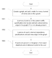
- FIG. 13 illustrates a flowchart for detecting protocol level deadlocks in a system and deadlock free traffic mapping of traffic on a NoC interconnect channels using core's internal dependency specification and system traffic profile, in accordance with the example embodiments.
- the system uses high level specification to capture the internal dependencies within various cores in the system.
- the system takes the system traffic profile information as an input.
- the system begins building a dependency graph by adding a node for every independent message subset present at all channels of all cores.
- the system begins to add edges to the dependency graph based on the system traffic profile.
- An edge is added for a message between a pair of cores, between the graph nodes representing the core's channel's independent message subset that contains the message.
- the system begins to add edges to the dependency graph based on the core's internal dependency specification. Once all dependencies are added, at 1305 , the system checks (e.g. automatically) for a cyclic dependency in the current dependency graph. At 1306 , if a cycle is detected, then the system indicates (e.g., message to the user) a protocol level deadlock. User may decide to change the system traffic or core's design to address the deadlock. If no cycle is detected, then the system proceeds to 1307 and begins to add nodes to the current dependency graph. A node is added for each channel in the interconnect.
- the flowchart then proceeds to 1308 to map the messages in the system traffic profile to the interconnect channels using the procedure such as described in U.S. patent application Ser. No. 13/599,559. If all messages are mapped successfully without any cycle in the dependency graph then the system proceeds to 1310 to indicate (e.g., message to the user) a possible deadlock free mapping of the specified traffic.
- FIG. 14 illustrates an example computer system 1400 on which example implementations may be implemented.
- the computer system 1400 includes a server 1405 which may involve an I/O unit 1435 , storage 1460 , and a processor 1410 operable to execute one or more units as known to one of skill in the art.
- the term “computer-readable medium” as used herein refers to any medium that participates in providing instructions to processor 1410 for execution, which may come in the form of computer-readable storage mediums, such as, but not limited to optical disks, magnetic disks, read-only memories, random access memories, solid state devices and drives, or any other types of tangible media suitable for storing electronic information, or computer-readable signal mediums, which can include transitory media such as carrier waves.
- the I/O unit processes input from user interfaces 1440 and operator interfaces 1445 which may utilize input devices such as a keyboard, mouse, touch device, or verbal command.
- the server 1405 may also be connected to an external storage 1450 , which can contain removable storage such as a portable hard drive, optical media (CD or DVD), disk media or any other medium from which a computer can read executable code.
- the server may also be connected an output device 1455 , such as a display to output data and other information to a user, as well as request additional information from a user.
- the connections from the server 1405 to the user interface 1440 , the operator interface 1445 , the external storage 1450 , and the output device 1455 may via wireless protocols, such as the 802.11 standards, Bluetooth® or cellular protocols, or via physical transmission media, such as cables or fiber optics.
- the output device 1055 may therefore further act as an input device for interacting with a user.
- the processor 1410 may execute one or more modules.
- the core internal dependency specification module 1411 is configured to capture the internal dependencies within a core using a high level specification. The specification of every core in the system is stored internally for protocol level deadlock analysis later.
- the protocol dependency graph module 1412 may be configured to take the global system traffic profile and core's internal dependency specifications as the input and automatically construct a dependency graph consisting of various nodes and edges representing various dependencies in the system. This module may check for cyclic dependencies in the dependency graph to determine whether the system may have protocol level deadlocks and may report them to the user.
- the interconnect mapping module 1413 may be configured to map various messages in the traffic profile to interconnect channels if no protocol level deadlock is present and avoid network level deadlock using multiple channels in the interconnect.
- the dependency specification module 1411 , the protocol dependency graph module 1412 , and the interconnect mapping module 1413 may interact with each other in various ways depending on the desired implementation.
- protocol dependency graph module 1412 may be utilized to notify deadlock scenarios to the users and the internal dependency specification module 1411 may be used to capture any design or traffic changes users make to address the deadlock and then feed these changes back to the protocol dependency graph module 1412 for deadlock analysis.
- the interconnect mapping module 1413 may allocate channels based on resource sharing and minimization, load balancing or other possible factors and give feedback to the user if resources are exhausted and receive the new system configuration from the other two modules.
Abstract
Description

Claims (18)
Priority Applications (2)
| Application Number | Priority Date | Filing Date | Title |
|---|---|---|---|
| US13/745,684 US9009648B2 (en) | 2013-01-18 | 2013-01-18 | Automatic deadlock detection and avoidance in a system interconnect by capturing internal dependencies of IP cores using high level specification |
| PCT/US2014/012003 WO2014113646A1 (en) | 2013-01-18 | 2014-01-17 | Automatic deadlock detection and avoidance in a system interconnect by capturing internal dependencies of ip cores using high level specification |
Applications Claiming Priority (1)
| Application Number | Priority Date | Filing Date | Title |
|---|---|---|---|
| US13/745,684 US9009648B2 (en) | 2013-01-18 | 2013-01-18 | Automatic deadlock detection and avoidance in a system interconnect by capturing internal dependencies of IP cores using high level specification |
Publications (2)
| Publication Number | Publication Date |
|---|---|
| US20140204735A1 US20140204735A1 (en) | 2014-07-24 |
| US9009648B2 true US9009648B2 (en) | 2015-04-14 |
Family
ID=51207571
Family Applications (1)
| Application Number | Title | Priority Date | Filing Date |
|---|---|---|---|
| US13/745,684 Expired - Fee Related US9009648B2 (en) | 2013-01-18 | 2013-01-18 | Automatic deadlock detection and avoidance in a system interconnect by capturing internal dependencies of IP cores using high level specification |
Country Status (2)
| Country | Link |
|---|---|
| US (1) | US9009648B2 (en) |
| WO (1) | WO2014113646A1 (en) |
Cited By (9)
| Publication number | Priority date | Publication date | Assignee | Title |
|---|---|---|---|---|
| US20150117261A1 (en) * | 2013-10-24 | 2015-04-30 | Netspeed Systems | Using multiple traffic profiles to design a network on chip |
| US20170250926A1 (en) * | 2016-02-29 | 2017-08-31 | Oregon State University | Routerless networks-on-chip |
| EP3328008A1 (en) | 2016-11-24 | 2018-05-30 | Mellanox Technologies TLV Ltd. | Deadlock-free routing in lossless multidimensional cartesian topologies with minimal number of virtual buffers |
| US10083262B2 (en) * | 2014-03-31 | 2018-09-25 | Imagination Technologies Limited | Deadlock detection in hardware design using assertion based verification |
| US10462046B2 (en) | 2016-11-09 | 2019-10-29 | International Business Machines Corporation | Routing of data in network |
| US10880178B2 (en) | 2016-11-24 | 2020-12-29 | Mellanox Technologies Tlv Ltd. | Automatic assignment of coordinates to network elements interconnected in a cartesian topology |
| US10915154B1 (en) | 2019-08-08 | 2021-02-09 | Mellanox Technologies Tlv Ltd. | Raising maximal silicon die temperature using reliability model |
| US11108679B2 (en) | 2019-08-08 | 2021-08-31 | Mellanox Technologies Tlv Ltd. | Producing deadlock-free routes in lossless cartesian topologies with minimal number of virtual lanes |
| US11425027B2 (en) | 2020-11-01 | 2022-08-23 | Mellanox Technologies, Ltd. | Turn-based deadlock-free routing in a Cartesian topology |
Families Citing this family (11)
| Publication number | Priority date | Publication date | Assignee | Title |
|---|---|---|---|---|
| ITTO20130824A1 (en) * | 2013-10-11 | 2015-04-11 | St Microelectronics Grenoble 2 | SYSTEM FOR DESIGNING INTERCONNECTIVE PROVISIONS NETWORK ON CHIP |
| US11165717B2 (en) | 2015-10-26 | 2021-11-02 | Western Digital Technologies, Inc. | Fabric interconnection for memory banks based on network-on-chip methodology |
| US10243881B2 (en) * | 2015-10-27 | 2019-03-26 | Western Digital Technologies, Inc. | Multilayer 3D memory based on network-on-chip interconnection |
| US9509613B1 (en) * | 2016-02-08 | 2016-11-29 | International Business Machines Corporation | Mechanisms for deadlock avoidance support in network fabrics |
| US10630590B2 (en) * | 2016-07-14 | 2020-04-21 | Mellanox Technologies Tlv Ltd. | Credit loop deadlock detection and recovery in arbitrary topology networks |
| US10990724B1 (en) | 2019-12-27 | 2021-04-27 | Arteris, Inc. | System and method for incremental topology synthesis of a network-on-chip |
| US11418448B2 (en) | 2020-04-09 | 2022-08-16 | Arteris, Inc. | System and method for synthesis of a network-on-chip to determine optimal path with load balancing |
| US11601357B2 (en) | 2020-12-22 | 2023-03-07 | Arteris, Inc. | System and method for generation of quality metrics for optimization tasks in topology synthesis of a network |
| US11449655B2 (en) | 2020-12-30 | 2022-09-20 | Arteris, Inc. | Synthesis of a network-on-chip (NoC) using performance constraints and objectives |
| US20230096061A1 (en) * | 2021-09-29 | 2023-03-30 | Arteris, Inc. | SYSTEM AND METHOD FOR DEADLOCK DETECTION IN NETWORK-ON-CHIP (NoC) HAVING EXTERNAL DEPENDENCIES |
| CN114760255B (en) * | 2022-03-31 | 2024-03-08 | 中国电子科技集团公司第五十八研究所 | On-chip and inter-chip integrated network deadlock-free architecture for multi-die interconnection |
Citations (83)
| Publication number | Priority date | Publication date | Assignee | Title |
|---|---|---|---|---|
| US4933933A (en) * | 1986-12-19 | 1990-06-12 | The California Institute Of Technology | Torus routing chip |
| US5105424A (en) * | 1988-06-02 | 1992-04-14 | California Institute Of Technology | Inter-computer message routing system with each computer having separate routinng automata for each dimension of the network |
| US5163016A (en) * | 1990-03-06 | 1992-11-10 | At&T Bell Laboratories | Analytical development and verification of control-intensive systems |
| US5432785A (en) | 1992-10-21 | 1995-07-11 | Bell Communications Research, Inc. | Broadband private virtual network service and system |
| US5583990A (en) * | 1993-12-10 | 1996-12-10 | Cray Research, Inc. | System for allocating messages between virtual channels to avoid deadlock and to optimize the amount of message traffic on each type of virtual channel |
| US5588152A (en) * | 1990-11-13 | 1996-12-24 | International Business Machines Corporation | Advanced parallel processor including advanced support hardware |
| US5764740A (en) | 1995-07-14 | 1998-06-09 | Telefonaktiebolaget Lm Ericsson | System and method for optimal logical network capacity dimensioning with broadband traffic |
| US5859981A (en) * | 1995-07-12 | 1999-01-12 | Super P.C., L.L.C. | Method for deadlock-free message passing in MIMD systems using routers and buffers |
| US5991308A (en) | 1995-08-25 | 1999-11-23 | Terayon Communication Systems, Inc. | Lower overhead method for data transmission using ATM and SCDMA over hybrid fiber coax cable plant |
| US6003029A (en) | 1997-08-22 | 1999-12-14 | International Business Machines Corporation | Automatic subspace clustering of high dimensional data for data mining applications |
| US6249902B1 (en) | 1998-01-09 | 2001-06-19 | Silicon Perspective Corporation | Design hierarchy-based placement |
| US20020073380A1 (en) | 1998-09-30 | 2002-06-13 | Cadence Design Systems, Inc. | Block based design methodology with programmable components |
| US20020071392A1 (en) | 2000-10-25 | 2002-06-13 | Telecommunications Research Laboratories, An Alberta Corporation | Design of a meta-mesh of chain sub-networks |
| US6415282B1 (en) | 1998-04-22 | 2002-07-02 | Nec Usa, Inc. | Method and apparatus for query refinement |
| US20020095430A1 (en) | 1999-12-30 | 2002-07-18 | Decode Genetics Ehf | SQL query generator utilizing matrix structures |
| US6674720B1 (en) * | 1999-09-29 | 2004-01-06 | Silicon Graphics, Inc. | Age-based network arbitration system and method |
| US6711717B2 (en) * | 2001-10-11 | 2004-03-23 | California Institute Of Technology | Method and system for compiling circuit designs |
| US20040216072A1 (en) | 2003-04-17 | 2004-10-28 | International Business Machines Corporation | Porosity aware buffered steiner tree construction |
| US20050147081A1 (en) | 2003-12-26 | 2005-07-07 | Swarup Acharya | Route determination method and apparatus for virtually-concatenated data traffic |
| US6925627B1 (en) | 2002-12-20 | 2005-08-02 | Conexant Systems, Inc. | Method and apparatus for power routing in an integrated circuit |
| US7046633B2 (en) * | 2000-09-21 | 2006-05-16 | Avici Systems, Inc. | Router implemented with a gamma graph interconnection network |
| US20060161875A1 (en) | 2005-01-06 | 2006-07-20 | Chae-Eun Rhee | Method of creating core-tile-switch mapping architecture in on-chip bus and computer-readable medium for recording the method |
| US20070118320A1 (en) | 2005-11-04 | 2007-05-24 | Synopsys, Inc. | Simulating topography of a conductive material in a semiconductor wafer |
| US20070244676A1 (en) | 2006-03-03 | 2007-10-18 | Li Shang | Adaptive analysis methods |
| US20070256044A1 (en) | 2006-04-26 | 2007-11-01 | Gary Coryer | System and method to power route hierarchical designs that employ macro reuse |
| US20070267680A1 (en) | 2006-05-17 | 2007-11-22 | Kabushiki Kaisha Toshiba | Semiconductor integrated circuit device |
| US7318214B1 (en) | 2003-06-19 | 2008-01-08 | Invarium, Inc. | System and method for reducing patterning variability in integrated circuit manufacturing through mask layout corrections |
| US20080072182A1 (en) | 2006-09-19 | 2008-03-20 | The Regents Of The University Of California | Structured and parameterized model order reduction |
| US20080120129A1 (en) | 2006-05-13 | 2008-05-22 | Michael Seubert | Consistent set of interfaces derived from a business object model |
| US7379424B1 (en) * | 2003-08-18 | 2008-05-27 | Cray Inc. | Systems and methods for routing packets in multiprocessor computer systems |
| US7437518B2 (en) * | 2005-09-07 | 2008-10-14 | Intel Corporation | Hiding conflict, coherence completion and transaction ID elements of a coherence protocol |
| US7461236B1 (en) * | 2005-03-25 | 2008-12-02 | Tilera Corporation | Transferring data in a parallel processing environment |
| US20090037888A1 (en) * | 2007-07-30 | 2009-02-05 | Fujitsu Limited | Simulation of program execution to detect problem such as deadlock |
| US20090070726A1 (en) | 2005-06-09 | 2009-03-12 | Pyxis Technology, Inc. | Enhanced Routing Grid System and Method |
| US7509619B1 (en) * | 2005-06-22 | 2009-03-24 | Xilinx, Inc. | Auto generation of a multi-staged processing pipeline hardware implementation for designs captured in high level languages |
| US20090172304A1 (en) * | 2007-12-28 | 2009-07-02 | Shay Gueron | Obscuring Memory Access Patterns in Conjunction with Deadlock Detection or Avoidance |
| US7590959B2 (en) | 2005-10-31 | 2009-09-15 | Seiko Epson Corporation | Layout system, layout program, and layout method for text or other layout elements along a grid |
| US20090268677A1 (en) | 2008-04-24 | 2009-10-29 | National Taiwan University | network resource allocation system and method of the same |
| US20090313592A1 (en) | 2006-10-10 | 2009-12-17 | Ecole Polytechnique Federale De Lausanne (Epfl) | Method to design network-on-chip (noc) - based communication systems |
| US20100040162A1 (en) | 2007-04-10 | 2010-02-18 | Naoki Suehiro | Transmission method, transmission device, receiving method, and receiving device |
| US7725859B1 (en) | 2003-08-01 | 2010-05-25 | Cadence Design Systems, Inc. | Methods and mechanisms for inserting metal fill data |
| US20100158005A1 (en) * | 2008-12-23 | 2010-06-24 | Suvhasis Mukhopadhyay | System-On-a-Chip and Multi-Chip Systems Supporting Advanced Telecommunication Functions |
| US7774783B2 (en) * | 2004-12-23 | 2010-08-10 | Microsoft Corporation | Method and apparatus for detecting deadlocks |
| US7808968B1 (en) | 1998-07-06 | 2010-10-05 | At&T Intellectual Property Ii, L.P. | Method for determining non-broadcast multiple access (NBMA) connectivity for routers having multiple local NBMA interfaces |
| US20110035523A1 (en) | 2009-08-07 | 2011-02-10 | Brett Stanley Feero | Communication infrastructure for a data processing apparatus and a method of operation of such a communication infrastructure |
| US20110060831A1 (en) | 2008-06-12 | 2011-03-10 | Tomoki Ishii | Network monitoring device, bus system monitoring device, method and program |
| US20110072407A1 (en) | 2009-09-18 | 2011-03-24 | International Business Machines Corporation | Automatic Positioning of Gate Array Circuits in an Integrated Circuit Design |
| US7917885B2 (en) | 2005-06-27 | 2011-03-29 | Tela Innovations, Inc. | Methods for creating primitive constructed standard cells |
| US20110154282A1 (en) | 2009-12-17 | 2011-06-23 | Springsoft, Inc. | Systems and methods for designing and making integrated circuits with consideration of wiring demand ratio |
| US8050256B1 (en) | 2008-07-08 | 2011-11-01 | Tilera Corporation | Configuring routing in mesh networks |
| US20110276937A1 (en) | 2005-06-24 | 2011-11-10 | Pulsic Limited | Integrated Circuit Routing with Compaction |
| US8059551B2 (en) | 2005-02-15 | 2011-11-15 | Raytheon Bbn Technologies Corp. | Method for source-spoofed IP packet traceback |
| US8099757B2 (en) | 2007-10-15 | 2012-01-17 | Time Warner Cable Inc. | Methods and apparatus for revenue-optimized delivery of content in a network |
| US20120023473A1 (en) | 2010-07-21 | 2012-01-26 | Brown Jeffrey S | Granular channel width for power optimization |
| US20120022841A1 (en) | 2010-07-22 | 2012-01-26 | Polyhedron Software Ltd. | Method and apparatus for estimating the state of a system |
| US20120026917A1 (en) | 2009-01-09 | 2012-02-02 | Microsoft Corporation | Server-centric high performance network architecture for modular data centers |
| US8136071B2 (en) | 2007-09-12 | 2012-03-13 | Neal Solomon | Three dimensional integrated circuits and methods of fabrication |
| US20120110541A1 (en) | 2010-10-29 | 2012-05-03 | International Business Machines Corporation | Constraint optimization of sub-net level routing in asic design |
| US20120155250A1 (en) | 2010-12-21 | 2012-06-21 | Verizon Patent And Licensing Inc. | Method and system of providing micro-facilities for network recovery |
| US20120173846A1 (en) * | 2010-12-30 | 2012-07-05 | Stmicroelectronics (Beijing) R&D Co., Ltd. | Method to reduce the energy cost of network-on-chip systems |
| US8281297B2 (en) | 2003-02-05 | 2012-10-02 | Arizona Board Of Regents | Reconfigurable processing |
| US8312402B1 (en) | 2008-12-08 | 2012-11-13 | Cadence Design Systems, Inc. | Method and apparatus for broadband electromagnetic modeling of three-dimensional interconnects embedded in multilayered substrates |
| US20130051397A1 (en) | 2011-08-26 | 2013-02-28 | Sonics, Inc. | Credit flow control scheme in a router with flexible link widths utilizing minimal storage |
| US20130080073A1 (en) | 2010-06-11 | 2013-03-28 | Waters Technologies Corporation | Techniques for mass spectrometry peak list computation using parallel processing |
| US20130103369A1 (en) | 2011-10-25 | 2013-04-25 | Massachusetts Institute Of Technology | Methods and apparatus for constructing and analyzing component-based models of engineering systems |
| US8448102B2 (en) | 2006-03-09 | 2013-05-21 | Tela Innovations, Inc. | Optimizing layout of irregular structures in regular layout context |
| US20130151215A1 (en) | 2011-12-12 | 2013-06-13 | Schlumberger Technology Corporation | Relaxed constraint delaunay method for discretizing fractured media |
| US20130159944A1 (en) | 2011-12-15 | 2013-06-20 | Taiga Uno | Flare map calculating method and recording medium |
| US20130174113A1 (en) | 2011-12-30 | 2013-07-04 | Arteris SAS | Floorplan estimation |
| US8492886B2 (en) | 2010-02-16 | 2013-07-23 | Monolithic 3D Inc | 3D integrated circuit with logic |
| US20130207801A1 (en) | 2012-02-14 | 2013-08-15 | James Barnes | Approach for prioritizing network alerts |
| US20130219148A1 (en) | 2012-02-17 | 2013-08-22 | National Taiwan University | Network on chip processor with multiple cores and routing method thereof |
| US8541819B1 (en) | 2010-12-09 | 2013-09-24 | Monolithic 3D Inc. | Semiconductor device and structure |
| US20130263068A1 (en) | 2012-03-27 | 2013-10-03 | International Business Machines Corporation | Relative ordering circuit synthesis |
| US8601423B1 (en) | 2012-10-23 | 2013-12-03 | Netspeed Systems | Asymmetric mesh NoC topologies |
| US20130326458A1 (en) | 2012-06-01 | 2013-12-05 | International Business Machines Corporation | Timing refinement re-routing |
| US8667439B1 (en) | 2013-02-27 | 2014-03-04 | Netspeed Systems | Automatically connecting SoCs IP cores to interconnect nodes to minimize global latency and reduce interconnect cost |
| US20140068132A1 (en) * | 2012-08-30 | 2014-03-06 | Netspeed Systems | Automatic construction of deadlock free interconnects |
| US20140092740A1 (en) | 2012-09-29 | 2014-04-03 | Ren Wang | Adaptive packet deflection to achieve fair, low-cost, and/or energy-efficient quality of service in network on chip devices |
| US20140098683A1 (en) | 2012-10-09 | 2014-04-10 | Netspeed Systems | Heterogeneous channel capacities in an interconnect |
| US8717875B2 (en) | 2011-04-15 | 2014-05-06 | Alcatel Lucent | Condensed core-energy-efficient architecture for WAN IP backbones |
| US20140211622A1 (en) * | 2013-01-28 | 2014-07-31 | Netspeed Systems | Creating multiple noc layers for isolation or avoiding noc traffic congestion |
| US20140254388A1 (en) * | 2013-03-11 | 2014-09-11 | Netspeed Systems | Reconfigurable noc for customizing traffic and optimizing performance after noc synthesis |
-
2013
- 2013-01-18 US US13/745,684 patent/US9009648B2/en not_active Expired - Fee Related
-
2014
- 2014-01-17 WO PCT/US2014/012003 patent/WO2014113646A1/en active Application Filing
Patent Citations (92)
| Publication number | Priority date | Publication date | Assignee | Title |
|---|---|---|---|---|
| US4933933A (en) * | 1986-12-19 | 1990-06-12 | The California Institute Of Technology | Torus routing chip |
| US5105424A (en) * | 1988-06-02 | 1992-04-14 | California Institute Of Technology | Inter-computer message routing system with each computer having separate routinng automata for each dimension of the network |
| US5163016A (en) * | 1990-03-06 | 1992-11-10 | At&T Bell Laboratories | Analytical development and verification of control-intensive systems |
| US5588152A (en) * | 1990-11-13 | 1996-12-24 | International Business Machines Corporation | Advanced parallel processor including advanced support hardware |
| US5432785A (en) | 1992-10-21 | 1995-07-11 | Bell Communications Research, Inc. | Broadband private virtual network service and system |
| US5583990A (en) * | 1993-12-10 | 1996-12-10 | Cray Research, Inc. | System for allocating messages between virtual channels to avoid deadlock and to optimize the amount of message traffic on each type of virtual channel |
| US5859981A (en) * | 1995-07-12 | 1999-01-12 | Super P.C., L.L.C. | Method for deadlock-free message passing in MIMD systems using routers and buffers |
| US5764740A (en) | 1995-07-14 | 1998-06-09 | Telefonaktiebolaget Lm Ericsson | System and method for optimal logical network capacity dimensioning with broadband traffic |
| US5991308A (en) | 1995-08-25 | 1999-11-23 | Terayon Communication Systems, Inc. | Lower overhead method for data transmission using ATM and SCDMA over hybrid fiber coax cable plant |
| US6003029A (en) | 1997-08-22 | 1999-12-14 | International Business Machines Corporation | Automatic subspace clustering of high dimensional data for data mining applications |
| US6249902B1 (en) | 1998-01-09 | 2001-06-19 | Silicon Perspective Corporation | Design hierarchy-based placement |
| US6415282B1 (en) | 1998-04-22 | 2002-07-02 | Nec Usa, Inc. | Method and apparatus for query refinement |
| US7808968B1 (en) | 1998-07-06 | 2010-10-05 | At&T Intellectual Property Ii, L.P. | Method for determining non-broadcast multiple access (NBMA) connectivity for routers having multiple local NBMA interfaces |
| US20020073380A1 (en) | 1998-09-30 | 2002-06-13 | Cadence Design Systems, Inc. | Block based design methodology with programmable components |
| US6674720B1 (en) * | 1999-09-29 | 2004-01-06 | Silicon Graphics, Inc. | Age-based network arbitration system and method |
| US20020095430A1 (en) | 1999-12-30 | 2002-07-18 | Decode Genetics Ehf | SQL query generator utilizing matrix structures |
| US7046633B2 (en) * | 2000-09-21 | 2006-05-16 | Avici Systems, Inc. | Router implemented with a gamma graph interconnection network |
| US20020071392A1 (en) | 2000-10-25 | 2002-06-13 | Telecommunications Research Laboratories, An Alberta Corporation | Design of a meta-mesh of chain sub-networks |
| US6711717B2 (en) * | 2001-10-11 | 2004-03-23 | California Institute Of Technology | Method and system for compiling circuit designs |
| US6925627B1 (en) | 2002-12-20 | 2005-08-02 | Conexant Systems, Inc. | Method and apparatus for power routing in an integrated circuit |
| US8281297B2 (en) | 2003-02-05 | 2012-10-02 | Arizona Board Of Regents | Reconfigurable processing |
| US7065730B2 (en) | 2003-04-17 | 2006-06-20 | International Business Machines Corporation | Porosity aware buffered steiner tree construction |
| US20040216072A1 (en) | 2003-04-17 | 2004-10-28 | International Business Machines Corporation | Porosity aware buffered steiner tree construction |
| US7318214B1 (en) | 2003-06-19 | 2008-01-08 | Invarium, Inc. | System and method for reducing patterning variability in integrated circuit manufacturing through mask layout corrections |
| US7725859B1 (en) | 2003-08-01 | 2010-05-25 | Cadence Design Systems, Inc. | Methods and mechanisms for inserting metal fill data |
| US7379424B1 (en) * | 2003-08-18 | 2008-05-27 | Cray Inc. | Systems and methods for routing packets in multiprocessor computer systems |
| US20050147081A1 (en) | 2003-12-26 | 2005-07-07 | Swarup Acharya | Route determination method and apparatus for virtually-concatenated data traffic |
| US7774783B2 (en) * | 2004-12-23 | 2010-08-10 | Microsoft Corporation | Method and apparatus for detecting deadlocks |
| US20060161875A1 (en) | 2005-01-06 | 2006-07-20 | Chae-Eun Rhee | Method of creating core-tile-switch mapping architecture in on-chip bus and computer-readable medium for recording the method |
| US8059551B2 (en) | 2005-02-15 | 2011-11-15 | Raytheon Bbn Technologies Corp. | Method for source-spoofed IP packet traceback |
| US7853774B1 (en) * | 2005-03-25 | 2010-12-14 | Tilera Corporation | Managing buffer storage in a parallel processing environment |
| US7461236B1 (en) * | 2005-03-25 | 2008-12-02 | Tilera Corporation | Transferring data in a parallel processing environment |
| US20090070726A1 (en) | 2005-06-09 | 2009-03-12 | Pyxis Technology, Inc. | Enhanced Routing Grid System and Method |
| US7509619B1 (en) * | 2005-06-22 | 2009-03-24 | Xilinx, Inc. | Auto generation of a multi-staged processing pipeline hardware implementation for designs captured in high level languages |
| US20110276937A1 (en) | 2005-06-24 | 2011-11-10 | Pulsic Limited | Integrated Circuit Routing with Compaction |
| US7917885B2 (en) | 2005-06-27 | 2011-03-29 | Tela Innovations, Inc. | Methods for creating primitive constructed standard cells |
| US7437518B2 (en) * | 2005-09-07 | 2008-10-14 | Intel Corporation | Hiding conflict, coherence completion and transaction ID elements of a coherence protocol |
| US7590959B2 (en) | 2005-10-31 | 2009-09-15 | Seiko Epson Corporation | Layout system, layout program, and layout method for text or other layout elements along a grid |
| US20070118320A1 (en) | 2005-11-04 | 2007-05-24 | Synopsys, Inc. | Simulating topography of a conductive material in a semiconductor wafer |
| US20070244676A1 (en) | 2006-03-03 | 2007-10-18 | Li Shang | Adaptive analysis methods |
| US8448102B2 (en) | 2006-03-09 | 2013-05-21 | Tela Innovations, Inc. | Optimizing layout of irregular structures in regular layout context |
| US20070256044A1 (en) | 2006-04-26 | 2007-11-01 | Gary Coryer | System and method to power route hierarchical designs that employ macro reuse |
| US20080120129A1 (en) | 2006-05-13 | 2008-05-22 | Michael Seubert | Consistent set of interfaces derived from a business object model |
| US20070267680A1 (en) | 2006-05-17 | 2007-11-22 | Kabushiki Kaisha Toshiba | Semiconductor integrated circuit device |
| US20080072182A1 (en) | 2006-09-19 | 2008-03-20 | The Regents Of The University Of California | Structured and parameterized model order reduction |
| US20090313592A1 (en) | 2006-10-10 | 2009-12-17 | Ecole Polytechnique Federale De Lausanne (Epfl) | Method to design network-on-chip (noc) - based communication systems |
| US20100040162A1 (en) | 2007-04-10 | 2010-02-18 | Naoki Suehiro | Transmission method, transmission device, receiving method, and receiving device |
| US20090037888A1 (en) * | 2007-07-30 | 2009-02-05 | Fujitsu Limited | Simulation of program execution to detect problem such as deadlock |
| US8136071B2 (en) | 2007-09-12 | 2012-03-13 | Neal Solomon | Three dimensional integrated circuits and methods of fabrication |
| US8099757B2 (en) | 2007-10-15 | 2012-01-17 | Time Warner Cable Inc. | Methods and apparatus for revenue-optimized delivery of content in a network |
| US20090172304A1 (en) * | 2007-12-28 | 2009-07-02 | Shay Gueron | Obscuring Memory Access Patterns in Conjunction with Deadlock Detection or Avoidance |
| US8407425B2 (en) * | 2007-12-28 | 2013-03-26 | Intel Corporation | Obscuring memory access patterns in conjunction with deadlock detection or avoidance |
| US20090268677A1 (en) | 2008-04-24 | 2009-10-29 | National Taiwan University | network resource allocation system and method of the same |
| US20110060831A1 (en) | 2008-06-12 | 2011-03-10 | Tomoki Ishii | Network monitoring device, bus system monitoring device, method and program |
| US8050256B1 (en) | 2008-07-08 | 2011-11-01 | Tilera Corporation | Configuring routing in mesh networks |
| US8312402B1 (en) | 2008-12-08 | 2012-11-13 | Cadence Design Systems, Inc. | Method and apparatus for broadband electromagnetic modeling of three-dimensional interconnects embedded in multilayered substrates |
| US20100158005A1 (en) * | 2008-12-23 | 2010-06-24 | Suvhasis Mukhopadhyay | System-On-a-Chip and Multi-Chip Systems Supporting Advanced Telecommunication Functions |
| US20120026917A1 (en) | 2009-01-09 | 2012-02-02 | Microsoft Corporation | Server-centric high performance network architecture for modular data centers |
| US20110035523A1 (en) | 2009-08-07 | 2011-02-10 | Brett Stanley Feero | Communication infrastructure for a data processing apparatus and a method of operation of such a communication infrastructure |
| US20110072407A1 (en) | 2009-09-18 | 2011-03-24 | International Business Machines Corporation | Automatic Positioning of Gate Array Circuits in an Integrated Circuit Design |
| US20110154282A1 (en) | 2009-12-17 | 2011-06-23 | Springsoft, Inc. | Systems and methods for designing and making integrated circuits with consideration of wiring demand ratio |
| US8492886B2 (en) | 2010-02-16 | 2013-07-23 | Monolithic 3D Inc | 3D integrated circuit with logic |
| US20130080073A1 (en) | 2010-06-11 | 2013-03-28 | Waters Technologies Corporation | Techniques for mass spectrometry peak list computation using parallel processing |
| US20120023473A1 (en) | 2010-07-21 | 2012-01-26 | Brown Jeffrey S | Granular channel width for power optimization |
| US20120022841A1 (en) | 2010-07-22 | 2012-01-26 | Polyhedron Software Ltd. | Method and apparatus for estimating the state of a system |
| US8543964B2 (en) | 2010-10-29 | 2013-09-24 | International Business Machines Corporation | Constraint optimization of sub-net level routing in asic design |
| US20120110541A1 (en) | 2010-10-29 | 2012-05-03 | International Business Machines Corporation | Constraint optimization of sub-net level routing in asic design |
| US8541819B1 (en) | 2010-12-09 | 2013-09-24 | Monolithic 3D Inc. | Semiconductor device and structure |
| US20120155250A1 (en) | 2010-12-21 | 2012-06-21 | Verizon Patent And Licensing Inc. | Method and system of providing micro-facilities for network recovery |
| US20120173846A1 (en) * | 2010-12-30 | 2012-07-05 | Stmicroelectronics (Beijing) R&D Co., Ltd. | Method to reduce the energy cost of network-on-chip systems |
| US8717875B2 (en) | 2011-04-15 | 2014-05-06 | Alcatel Lucent | Condensed core-energy-efficient architecture for WAN IP backbones |
| US20130051397A1 (en) | 2011-08-26 | 2013-02-28 | Sonics, Inc. | Credit flow control scheme in a router with flexible link widths utilizing minimal storage |
| US20130103369A1 (en) | 2011-10-25 | 2013-04-25 | Massachusetts Institute Of Technology | Methods and apparatus for constructing and analyzing component-based models of engineering systems |
| US20130151215A1 (en) | 2011-12-12 | 2013-06-13 | Schlumberger Technology Corporation | Relaxed constraint delaunay method for discretizing fractured media |
| US20130159944A1 (en) | 2011-12-15 | 2013-06-20 | Taiga Uno | Flare map calculating method and recording medium |
| US20130174113A1 (en) | 2011-12-30 | 2013-07-04 | Arteris SAS | Floorplan estimation |
| US20130207801A1 (en) | 2012-02-14 | 2013-08-15 | James Barnes | Approach for prioritizing network alerts |
| US20130219148A1 (en) | 2012-02-17 | 2013-08-22 | National Taiwan University | Network on chip processor with multiple cores and routing method thereof |
| US20130263068A1 (en) | 2012-03-27 | 2013-10-03 | International Business Machines Corporation | Relative ordering circuit synthesis |
| US20130326458A1 (en) | 2012-06-01 | 2013-12-05 | International Business Machines Corporation | Timing refinement re-routing |
| US8635577B2 (en) | 2012-06-01 | 2014-01-21 | International Business Machines Corporation | Timing refinement re-routing |
| US20140068132A1 (en) * | 2012-08-30 | 2014-03-06 | Netspeed Systems | Automatic construction of deadlock free interconnects |
| CN103684961A (en) | 2012-08-30 | 2014-03-26 | 网速系统公司 | Automatic construction of deadlock free interconnects |
| US20140092740A1 (en) | 2012-09-29 | 2014-04-03 | Ren Wang | Adaptive packet deflection to achieve fair, low-cost, and/or energy-efficient quality of service in network on chip devices |
| WO2014059024A1 (en) | 2012-10-09 | 2014-04-17 | Netspeed Systems | Heterogeneous channel capacities in an interconnect |
| US20140098683A1 (en) | 2012-10-09 | 2014-04-10 | Netspeed Systems | Heterogeneous channel capacities in an interconnect |
| US20140115218A1 (en) | 2012-10-23 | 2014-04-24 | Netspeed Systems | ASYMMETRIC MESH NoC TOPOLOGIES |
| US20140115298A1 (en) | 2012-10-23 | 2014-04-24 | Netspeed Systems | ASYMMETRIC MESH NoC TOPOLOGIES |
| US8601423B1 (en) | 2012-10-23 | 2013-12-03 | Netspeed Systems | Asymmetric mesh NoC topologies |
| US20140211622A1 (en) * | 2013-01-28 | 2014-07-31 | Netspeed Systems | Creating multiple noc layers for isolation or avoiding noc traffic congestion |
| US8667439B1 (en) | 2013-02-27 | 2014-03-04 | Netspeed Systems | Automatically connecting SoCs IP cores to interconnect nodes to minimize global latency and reduce interconnect cost |
| US20140254388A1 (en) * | 2013-03-11 | 2014-09-11 | Netspeed Systems | Reconfigurable noc for customizing traffic and optimizing performance after noc synthesis |
Non-Patent Citations (17)
| Title |
|---|
| Ababei, C., et al., Achieving Network on Chip Fault Tolerance by Adaptive Remapping, Parallel & Distributed Processing, 2009, IEEE International Symposium, 4 pgs. |
| Abts, D., et al., Age-Based Packet Arbitration in Large-Radix k-ary n-cubes, Supercomputing 2007 (SC07), Nov. 10-16, 2007, 11 pgs. |
| Beretta, I, et al., A Mapping Flow for Dynamically Reconfigurable Multi-Core System-on-Chip Design, IEEE Transactions on Computer-Aided Design of Integrated Circuits and Systems, Aug. 2011, 30(8), pp. 1211-1224. |
| Das, R., et al., Aergia: Exploiting Packet Latency Slack in On-Chip Networks, 37th International Symposium on Computer Architecture (ISCA '10), Jun. 19-23, 2010, 11 pgs. |
| Ebrahimi, E., et al., Fairness via Source Throttling: A Configurable and High-Performance Fairness Substrate for Multi-Core Memory Systems, ASPLOS '10, Mar. 13-17, 2010, 12 pgs. |
| Gindin, R., et al., NoC-Based FPGA: Architecture and Routing, Proceedings of the First International Symposium on Networks-on-Chip (NOCS'07), May 2007, pp. 253-262. |
| Grot, B., Kilo-NOC: A Heterogeneous Network-on-Chip Architecture for Scalability and Service Guarantees, ISCA '11, Jun. 4-8, 2011, 12 pgs. |
| Grot, B., Preemptive Virtual Clock: A Flexible, Efficient, and Cost-Effective QOS Scheme for Networks-on-Chip, Micro '09, Dec. 12-16, 2009, 12 pgs. |
| Grot, B., Topology-Aware Quality-of-Service Support in Highly Integrated Chip Multiprocessors, 6th Annual Workshop on the Interaction between Operating Systems and Computer Architecture, Jun. 2006, 11 pgs. |
| International Search Report and Written Opinion for PCT/US2013/064140, Jan. 22, 2014, 9 pgs. |
| International Search Report and Written Opinion for PCT/US2014/012003, Mar. 26, 2014, 9 pgs. |
| International Search Report and Written Opinion for PCT/US2014/012012, May 14, 2014, 9 pgs. |
| Jiang, N., et al., Performance Implications of Age-Based Allocations in On-Chip Networks, CVA MEMO 129, May 24, 2011, 21 pgs. |
| Lee, J. W., et al., Globally-Synchronized Frames for Guaranteed Quality-of-Service in On-Chip Networks, 35th IEEE/ACM International Symposium on Computer Architecture (ISCA), Jun. 2008, 12 pgs. |
| Lee, M. M., et al., Approximating Age-Based Arbitration in On-Chip Networks, PACT '10, Sep. 11-15, 2010, 2 pgs. |
| Li, B., et al., CoQoS: Coordinating QoS-Aware Shared Resources in NoC-based SoCs, J. Parallel Distrib. Comput., 71(5), May 2011, 14 pgs. |
| Yang, J., et al., Homogeneous NoC-based FPGA: The Foundation for Virtual FPGA, 10th IEEE International Conference on Computer and Informaiton Technology (CIT 2010), Jun. 2010, pp. 62-67. |
Cited By (14)
| Publication number | Priority date | Publication date | Assignee | Title |
|---|---|---|---|---|
| US9294354B2 (en) * | 2013-10-24 | 2016-03-22 | Netspeed Systems | Using multiple traffic profiles to design a network on chip |
| US20150117261A1 (en) * | 2013-10-24 | 2015-04-30 | Netspeed Systems | Using multiple traffic profiles to design a network on chip |
| US10083262B2 (en) * | 2014-03-31 | 2018-09-25 | Imagination Technologies Limited | Deadlock detection in hardware design using assertion based verification |
| US10657216B2 (en) * | 2016-02-29 | 2020-05-19 | Oregon State University | Routerless networks-on-chip |
| US20170250926A1 (en) * | 2016-02-29 | 2017-08-31 | Oregon State University | Routerless networks-on-chip |
| US10764657B2 (en) | 2016-11-09 | 2020-09-01 | International Business Machines Corporation | Routing of data in network |
| US10462046B2 (en) | 2016-11-09 | 2019-10-29 | International Business Machines Corporation | Routing of data in network |
| EP3328008A1 (en) | 2016-11-24 | 2018-05-30 | Mellanox Technologies TLV Ltd. | Deadlock-free routing in lossless multidimensional cartesian topologies with minimal number of virtual buffers |
| US10404574B2 (en) | 2016-11-24 | 2019-09-03 | Mellanox Technologies Tlv Ltd. | Deadlock-free routing in lossless multidimensional cartesian topologies with minimal number of virtual buffers |
| US10880178B2 (en) | 2016-11-24 | 2020-12-29 | Mellanox Technologies Tlv Ltd. | Automatic assignment of coordinates to network elements interconnected in a cartesian topology |
| US10915154B1 (en) | 2019-08-08 | 2021-02-09 | Mellanox Technologies Tlv Ltd. | Raising maximal silicon die temperature using reliability model |
| US11108679B2 (en) | 2019-08-08 | 2021-08-31 | Mellanox Technologies Tlv Ltd. | Producing deadlock-free routes in lossless cartesian topologies with minimal number of virtual lanes |
| US11770326B2 (en) | 2019-08-08 | 2023-09-26 | Mellanox Technologies, Ltd. | Producing deadlock-free routes in lossless cartesian topologies with minimal number of virtual lanes |
| US11425027B2 (en) | 2020-11-01 | 2022-08-23 | Mellanox Technologies, Ltd. | Turn-based deadlock-free routing in a Cartesian topology |
Also Published As
| Publication number | Publication date |
|---|---|
| WO2014113646A1 (en) | 2014-07-24 |
| US20140204735A1 (en) | 2014-07-24 |
Similar Documents
| Publication | Publication Date | Title |
|---|---|---|
| US9009648B2 (en) | Automatic deadlock detection and avoidance in a system interconnect by capturing internal dependencies of IP cores using high level specification | |
| US9244880B2 (en) | Automatic construction of deadlock free interconnects | |
| US9571420B2 (en) | Integrated NoC for performing data communication and NoC functions | |
| US9569579B1 (en) | Automatic pipelining of NoC channels to meet timing and/or performance | |
| US9294354B2 (en) | Using multiple traffic profiles to design a network on chip | |
| US9473388B2 (en) | Supporting multicast in NOC interconnect | |
| US9473359B2 (en) | Transactional traffic specification for network-on-chip design | |
| US9253085B2 (en) | Hierarchical asymmetric mesh with virtual routers | |
| US9477280B1 (en) | Specification for automatic power management of network-on-chip and system-on-chip | |
| US9054977B2 (en) | Automatic NoC topology generation | |
| US9781043B2 (en) | Identification of internal dependencies within system components for evaluating potential protocol level deadlocks | |
| US9160627B2 (en) | Multiple heterogeneous NoC layers | |
| US20150236963A1 (en) | Qos in a system with end-to-end flow control and qos aware buffer allocation | |
| US20090198956A1 (en) | System and Method for Data Processing Using a Low-Cost Two-Tier Full-Graph Interconnect Architecture | |
| US20150186277A1 (en) | Cache coherent noc with flexible number of cores, i/o devices, directory structure and coherency points | |
| US10896476B2 (en) | Repository of integration description of hardware intellectual property for NoC construction and SoC integration | |
| US9246792B2 (en) | Providing point to point communications among compute nodes in a global combining network of a parallel computer | |
| US10547514B2 (en) | Automatic crossbar generation and router connections for network-on-chip (NOC) topology generation | |
| US20180219738A1 (en) | Cost Management Against Requirements for the Generation of a NoC | |
| US9774498B2 (en) | Hierarchical asymmetric mesh with virtual routers | |
| US20180198682A1 (en) | Strategies for NoC Construction Using Machine Learning | |
| US9928204B2 (en) | Transaction expansion for NoC simulation and NoC design |
Legal Events
| Date | Code | Title | Description |
|---|---|---|---|
| AS | Assignment |
Owner name: NETSPEED SYSTEMS, CALIFORNIA Free format text: ASSIGNMENT OF ASSIGNORS INTEREST;ASSIGNORS:KUMAR, SAILESH;NORIGE, ERIC;PHILIP, JOJI;AND OTHERS;REEL/FRAME:029795/0837 Effective date: 20130117 |
|
| STCF | Information on status: patent grant |
Free format text: PATENTED CASE |
|
| MAFP | Maintenance fee payment |
Free format text: PAYMENT OF MAINTENANCE FEE, 4TH YR, SMALL ENTITY (ORIGINAL EVENT CODE: M2551); ENTITY STATUS OF PATENT OWNER: SMALL ENTITY Year of fee payment: 4 |
|
| FEPP | Fee payment procedure |
Free format text: ENTITY STATUS SET TO UNDISCOUNTED (ORIGINAL EVENT CODE: BIG.); ENTITY STATUS OF PATENT OWNER: LARGE ENTITY |
|
| AS | Assignment |
Owner name: INTEL CORPORATION, CALIFORNIA Free format text: ASSIGNMENT OF ASSIGNORS INTEREST;ASSIGNOR:NETSPEED SYSTEMS, INC.;REEL/FRAME:060753/0662 Effective date: 20220708 |
|
| FEPP | Fee payment procedure |
Free format text: MAINTENANCE FEE REMINDER MAILED (ORIGINAL EVENT CODE: REM.); ENTITY STATUS OF PATENT OWNER: LARGE ENTITY |
|
| LAPS | Lapse for failure to pay maintenance fees |
Free format text: PATENT EXPIRED FOR FAILURE TO PAY MAINTENANCE FEES (ORIGINAL EVENT CODE: EXP.); ENTITY STATUS OF PATENT OWNER: LARGE ENTITY |
|
| STCH | Information on status: patent discontinuation |
Free format text: PATENT EXPIRED DUE TO NONPAYMENT OF MAINTENANCE FEES UNDER 37 CFR 1.362 |
|
| FP | Lapsed due to failure to pay maintenance fee |
Effective date: 20230414 |