US8984336B1 - Systems and methods for performing first failure data captures - Google Patents
Systems and methods for performing first failure data captures Download PDFInfo
- Publication number
- US8984336B1 US8984336B1 US13/400,306 US201213400306A US8984336B1 US 8984336 B1 US8984336 B1 US 8984336B1 US 201213400306 A US201213400306 A US 201213400306A US 8984336 B1 US8984336 B1 US 8984336B1
- Authority
- US
- United States
- Prior art keywords
- resource
- context
- failure data
- old
- freeing
- Prior art date
- Legal status (The legal status is an assumption and is not a legal conclusion. Google has not performed a legal analysis and makes no representation as to the accuracy of the status listed.)
- Expired - Fee Related, expires
Links
Images


Classifications
-
- G—PHYSICS
- G06—COMPUTING; CALCULATING OR COUNTING
- G06F—ELECTRIC DIGITAL DATA PROCESSING
- G06F11/00—Error detection; Error correction; Monitoring
- G06F11/07—Responding to the occurrence of a fault, e.g. fault tolerance
- G06F11/0703—Error or fault processing not based on redundancy, i.e. by taking additional measures to deal with the error or fault not making use of redundancy in operation, in hardware, or in data representation
- G06F11/0766—Error or fault reporting or storing
- G06F11/0778—Dumping, i.e. gathering error/state information after a fault for later diagnosis
-
- G—PHYSICS
- G06—COMPUTING; CALCULATING OR COUNTING
- G06F—ELECTRIC DIGITAL DATA PROCESSING
- G06F11/00—Error detection; Error correction; Monitoring
- G06F11/07—Responding to the occurrence of a fault, e.g. fault tolerance
- G06F11/0703—Error or fault processing not based on redundancy, i.e. by taking additional measures to deal with the error or fault not making use of redundancy in operation, in hardware, or in data representation
- G06F11/0706—Error or fault processing not based on redundancy, i.e. by taking additional measures to deal with the error or fault not making use of redundancy in operation, in hardware, or in data representation the processing taking place on a specific hardware platform or in a specific software environment
- G06F11/0721—Error or fault processing not based on redundancy, i.e. by taking additional measures to deal with the error or fault not making use of redundancy in operation, in hardware, or in data representation the processing taking place on a specific hardware platform or in a specific software environment within a central processing unit [CPU]
-
- G—PHYSICS
- G06—COMPUTING; CALCULATING OR COUNTING
- G06F—ELECTRIC DIGITAL DATA PROCESSING
- G06F11/00—Error detection; Error correction; Monitoring
- G06F11/07—Responding to the occurrence of a fault, e.g. fault tolerance
- G06F11/14—Error detection or correction of the data by redundancy in operation
- G06F11/1479—Generic software techniques for error detection or fault masking
- G06F11/1482—Generic software techniques for error detection or fault masking by means of middleware or OS functionality
-
- G—PHYSICS
- G06—COMPUTING; CALCULATING OR COUNTING
- G06F—ELECTRIC DIGITAL DATA PROCESSING
- G06F11/00—Error detection; Error correction; Monitoring
- G06F11/07—Responding to the occurrence of a fault, e.g. fault tolerance
- G06F11/16—Error detection or correction of the data by redundancy in hardware
- G06F11/20—Error detection or correction of the data by redundancy in hardware using active fault-masking, e.g. by switching out faulty elements or by switching in spare elements
Definitions
- a first failure data capturing function may gather and/or analyze data within a failed process context. While performing a first failure data capture may provide valuable information for the future, the consequent delay to a complete exit of the failed process context may monopolize a resource allocated within the failed process context (e.g., until the operating system has resolved the old, failed process context). Since restarting the process in a new context may not be possible until the resource is released, performing the first failure data capture may significantly impact the high availability required of the process. Situations in which the first failure data capture involves large amounts of data and/or a host is under a high load may only exacerbate this problem. Accordingly, the instant disclosure identifies and addresses a need for additional and improved systems and methods for performing first failure data captures.
- a computer-implemented method for performing first failure data captures may include 1) identifying a process that has failed within an old process context and is undergoing a first failure data capture within the old process context, 2) identifying at least one resource allocated within the old process context and required for restarting the process in a new process context, 3) freeing the resource from the old process context before terminating the process within the old process context, and 4) initiating the process in the new process context before the process within the old process context has terminated.
- the failure of the process may arise in any of a variety of contexts.
- the process may have failed within a non-virtual environment.
- the resource may include any of a variety of resources.
- the resource may include 1) a file descriptor, 2) a shared memory handle, 3) a named pipe, 4) a named socket, 5) a named semaphore, and/or 6) a mapped file.
- freeing the resource from the old process context before terminating the process within the old process context may include 1) retrieving failure data for the first failure data capture from the resource and 2) freeing the resource after retrieving the failure data and before performing an additional first failure data capture operation within the old process context.
- the additional first failure data capture operation may include any of a variety of operations.
- the additional first failure data capture operation may include a core dump of the process.
- freeing the resource from the old process context before terminating the process within the old process context may include 1) loading failure data for the first failure data capture from the resource into volatile memory, 2) freeing the resource after retrieving the failure data, and 3) writing the failure data from the volatile memory to a failure log file after freeing the resource.
- the computer-implemented method may also include reducing a priority of the process within the old context.
- the computer-implemented method may reduce the priority of the process after freeing the resource.
- a system for implementing the above-described method may include 1) an identification module programmed to identify a process that has failed within an old process context and is undergoing a first failure data capture within the old process context, 2) a resource module programmed to identify at least one resource allocated within the old process context and required for restarting the process in a new process context, 3) a freeing module programmed to free the resource from the old process context before terminating the process within the old process context, and 4) an initiation module programmed to initiate the process in the new process context before the process within the old process context has terminated.
- the system may also include at least one processor configured to execute the identification module, the resource module, the freeing module, and the initiation module.
- a computer-readable-storage medium may include one or more computer-executable instructions that, when executed by at least one processor of a computing device, may cause the computing device to 1) identify a process that has failed within an old process context and is undergoing a first failure data capture within the old process context, 2) identify at least one resource allocated within the old process context and required for restarting the process in a new process context, 3) free the resource from the old process context before terminating the process within the old process context, and 4) initiate the process in the new process context before the process within the old process context has terminated.
- the systems and methods described herein may provide a lower time to recovery for processes without sacrificing the collection of debugging information. These systems and methods may thereby improve high availability linked to such processes, particularly on host systems with high load levels.
- FIG. 1 is a block diagram of an exemplary system for performing first failure data captures.
- FIG. 2 is a block diagram of an exemplary system for performing first failure data captures.
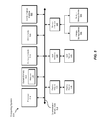
- FIG. 3 is a flow diagram of an exemplary method for performing first failure data captures.
- FIG. 4 is an illustration of an exemplary timeline for performing first failure data captures.
- FIG. 5 is a block diagram of an exemplary computing system capable of implementing one or more of the embodiments described and/or illustrated herein.
- FIG. 6 is a block diagram of an exemplary computing network capable of implementing one or more of the embodiments described and/or illustrated herein.
- FIGS. 1-2 detailed descriptions of exemplary systems for performing first failure data captures. Detailed descriptions of corresponding computer-implemented methods will also be provided in connection with FIG. 3 . Detailed descriptions of an exemplary timeline for first failure data captures will be provided in connection with FIG. 4 . In addition, detailed descriptions of an exemplary computing system and network architecture capable of implementing one or more of the embodiments described herein will be provided in connection with FIGS. 5 and 6 , respectively.
- FIG. 1 is a block diagram of an exemplary system 100 for performing first failure data captures.
- exemplary system 100 may include one or more modules 102 for performing one or more tasks.
- exemplary system 100 may include an identification module 104 programmed to identify a process that has failed within an old process context and is undergoing a first failure data capture within the old process context.
- exemplary system 100 may also include a resource module 106 programmed to identify at least one resource allocated within the old process context and required for restarting the process in a new process context.
- exemplary system 100 may include a freeing module 108 programmed to free the resource from the old process context before terminating the process within the old process context.
- exemplary system may also include an initiation module 110 programmed to initiate the process in the new process context before the process within the old process context has terminated.
- initiation module 110 programmed to initiate the process in the new process context before the process within the old process context has terminated.
- one or more of modules 102 in FIG. 1 may represent one or more software applications or programs that, when executed by a computing device, may cause the computing device to perform one or more tasks.
- one or more of modules 102 may represent software modules stored and configured to run on one or more computing devices, such as computing device 202 in FIG. 2 , computing system 510 in FIG. 5 , and/or portions of exemplary network architecture 600 in FIG. 6 .
- One or more of modules 102 in FIG. 1 may also represent all or portions of one or more special-purpose computers configured to perform one or more tasks.
- Exemplary system 100 in FIG. 1 may be implemented in a variety of ways. For example, all or a portion of exemplary system 100 may represent portions of exemplary system 200 in FIG. 2 . As shown in FIG. 2 , system 200 may include a computing device 202 configured to execute a process 212 (e.g., to provide high availability to data and/or services through computing device 202 ).
- a process 212 e.g., to provide high availability to data and/or services through computing device 202 .
- one or more of modules 102 from FIG. 1 may, when executed by at least one processor of computing device 202 , facilitate computing device 202 in performing first failure data captures. For example, and as will be described in greater detail below, one or more of modules 102 may cause computing device 202 to 1) identify a process 212 ( 1 ) that has failed within an old process context 210 and is undergoing a first failure data capture within context 210 , 2) identify a resource 220 allocated within context 210 and required for restarting process 212 ( 1 ) in a new process context 230 , 3) free resource 220 from context 210 (e.g., by terminating a resource allocation 222 ) before terminating process 212 ( 1 ) within context 210 , and 4) initiate process 212 ( 2 ) (e.g., and allocate resource 220 with a resource allocation 224 ) in context 230 before process 212 ( 1 ) within context 210 has terminated.
- process 212 ( 2 ) e.g., and allocate resource 220 with
- Computing device 202 generally represents any type or form of computing device capable of reading computer-executable instructions. Examples of computing device 202 include, without limitation, servers, desktops, tablets, laptops, cellular phones, personal digital assistants (PDAs), multimedia players, embedded systems, combinations of one or more of the same, exemplary computing system 510 in FIG. 5 , or any other suitable computing device.
- Examples of computing device 202 include, without limitation, servers, desktops, tablets, laptops, cellular phones, personal digital assistants (PDAs), multimedia players, embedded systems, combinations of one or more of the same, exemplary computing system 510 in FIG. 5 , or any other suitable computing device.
- FIG. 3 is a flow diagram of an exemplary computer-implemented method 300 for performing first failure data captures.
- the steps shown in FIG. 3 may be performed by any suitable computer-executable code and/or computing system. In some embodiments, the steps shown in FIG. 3 may be performed by one or more of the components of system 100 in FIG. 1 , system 200 in FIG. 2 , computing system 510 in FIG. 5 , and/or portions of exemplary network architecture 600 in FIG. 6 .
- one or more of the systems described herein may identify a process that has failed within an old process context and is undergoing a first failure data capture within the old process context.
- identification module 104 may, as part of computing device 202 in FIG. 2 , identify process 212 ( 1 ) that has failed within old process context 210 and is undergoing a first failure data capture within context 210 .
- the term “process” may refer to any program in execution (e.g., an instantiation and/or running copy of a program expressed by an executable file).
- the process may include an application, service, agent, and/or daemon in execution.
- “restarting” or “initiating” a process may refer to starting a new instantiation of any such program.
- the process may include multiple processes, threads, and/or subprocesses.
- the process may be configured for an immediate restart upon failure.
- the process may play a role in providing high availability to data and/or services.
- the process may fail within any of a variety of contexts.
- the process may fail within a non-virtual environment.
- the process may fail outside of any hypervisor and/or virtual machine.
- process context may refer to any instantiation of a process, separable state in which a process executes, and/or state information relating to a process.
- a process context may include and/or define one or more resource handles by which a process may access resources.
- first failure data capture may refer to any process for gathering and/or analyzing information from a process and/or process context upon a failure of a process.
- a first failure data capture may gather information from a process and/or process context before fully exiting and/or terminating the process and/or process context for future debugging purposes.
- the term “failure” as applied to a process may refer to any error and/or exception within the process leading to a first failure data capture of the process and/or termination of the process.
- Identification module 104 may identify the failed process in any suitable manner. For example, identification module 104 may identify the failed process by receiving a message from the failed process. Additionally or alternatively, identification module 104 may receive a message identifying the failed process. In some examples, identification module 104 may identify the failed process by executing within the old process context. In at least one example, identification module 104 may identify the failed process by executing as a part of a first failure data capture routine for the failed process.
- FIG. 4 illustrates an exemplary timeline 400 for performing first failure data captures.
- exemplary timeline 400 may include a failure 402 (e.g., of the process).
- identification module 104 may identify the process after failure 402 .
- one or more of the systems described herein may identify at least one resource allocated within the old process context and required for restarting the process in a new process context.
- resource module 106 may, as part of computing device 202 in FIG. 2 , identify resource 220 allocated within context 210 and required for restarting process 212 ( 1 ) in new process context 230 .
- the term “resource” may refer to any physical, logical, and/or virtual component of a computing system that may be used by and/or allocated to a process. Accordingly, the resource may include, a file descriptor (including, e.g., a file handle, a server socket, a device handle, etc.), a shared memory handle, a named pipe, a named socket, a named semaphore, and/or a mapped file. In at least one example, the resource may include a run and/or PID file. Generally, the resource may include any exclusive resource—e.g., a resource that cannot be and/or cannot safely be used and/or controlled simultaneously in more than one process context.
- Resource module 106 may identify the resource in any suitable manner. For example, resource module 106 may identify the resource by executing within the old process context to which the resource is allocated. In at least one example, resource module 106 may identify the failed process by executing as a part of a first failure data capture routine for the failed process. In some examples, resource module 106 may identify the resource by including a fixed and/or predefined name and/or identifier of the resource. Additionally or alternatively, resource module 106 may identify the resource by querying a database with an identifier of the process to identify at least one resource used and/or required by the process. In some examples, resource module 106 may identify the resource as a part of retrieving data from and/or relating to the resource.
- exemplary timeline 400 may include a resource data retrieval 404 and a resource release 406 .
- resource module 106 may identify the resource before and/or as a part of resource data retrieve 404 and/or resource release 406 .
- one or more of the systems described herein may free the resource from the old process context before terminating the process within the old process context.
- freeing module 108 may, as part of computing device 202 in FIG. 2 , free resource 220 from context 210 (e.g., by terminating resource allocation 222 ) before terminating process 212 ( 1 ) within context 210 .
- Freeing module 108 may free the resource from the old process context before terminating the process within the old process context in any of a variety of ways. For example, freeing module 108 may first retrieve failure data for the first failure data capture from the resource. Freeing module 108 may free the resource after retrieving the failure data and before performing an additional first failure data capture operation within the old process context.
- the phrase “failure data” may refer to any data that is potentially relevant to understanding, contextualizing, and/or analyzing the failure of a process. For example, if the resource includes a file handle, freeing module 108 may read from the file before releasing the file and performing additional first failure data capture operations. The additional first failure data capture operation may include any of a variety of operations.
- the additional first failure data capture operation may include a core dump of the process.
- the process may have included a large amount of working memory.
- the systems and methods described herein may free the resource substantially sooner than otherwise and, as will be explained in greater detail below, thereby allow the resource to be allocated to the process in a new process context more quickly.
- exemplary timeline 400 may include a new context initiation 408 (e.g., restarting the process within the new process context) after resource release 406 and before a core dump 414 .
- freeing the resource from the old process context before terminating the process within the old process context may include 1) loading failure data for the first failure data capture from the resource into volatile memory, 2) freeing the resource after retrieving the failure data, and 3) writing the failure data from the volatile memory to a failure log file after freeing the resource.
- the phrase “volatile memory” may include any temporary volatile and/or temporary storage location for data.
- the phrase “volatile memory” may refer to random access memory.
- the phrase “volatile memory” may refer to a storage location that allows for quicker write operations than a subsequent, more permanent storage location (e.g. the failure log file).
- resource data retrieval 404 may be followed directly by resource release 406 .
- Exemplary timeline 400 may also include a resource data logging 412 subsequent to resource release 406 and new context initiation 408 .
- Freeing module 108 may free the resource in any suitable context. For example, freeing module 108 may free the resource as a part of a first failure data capture routine. For example, freeing module 108 may free the resource within the same function and/or script as (and/or a function and/or script called by) the first failure data capture. Additionally or alternatively, freeing module 108 may be executed in response to a system call performed in response to the failure of the process. Using FIG. 4 as an example of step 306 , freeing module 108 may perform resource release 406 before an old context termination 416 .
- one or more of the systems described herein may initiate the process in the new process context before the process within the old process context has terminated.
- initiation module 110 may, as part of computing device 202 in FIG. 2 , initiate process 212 ( 2 ) (e.g., and allocate resource 220 with resource allocation 224 ) in context 230 before process 212 ( 1 ) within context 210 has terminated.
- Initiation module 110 may initiate the process in the new process context in any of a variety of ways. For example, initiation module 110 may initiate the process in the new process context by directly launching a new instantiation of the process. Additionally or alternatively, initiation module 110 may initiate the process by sending a message that the resource has been freed and/or the process is ready to be restarted. In some examples, initiation module 110 may operate as a part of a daemon configured to monitor the resource for availability in order to restart the process. Alternatively, initiation module 110 may initiate the process simply by having freed the resource, thereby allowing such a daemon to observe that the resource is free.
- initiation module 110 may also allocate (and/or facilitate the allocation of) the resource within the new process context before the process within the old process context has terminated. Using FIG. 4 as an example, initiation module 110 may perform and/or facilitate new context initiation 408 before old context termination 416 .
- one or more of the systems described herein may reprioritize the process within the old context.
- initiation module 110 may reduce a priority of the process within the old context.
- the term “priority” may refer to any value and/or condition determining the allocation of one or more resources to a process.
- initiation module 110 may reduce a priority of the process within the old context resulting in the process within the old context being scheduled for fewer processing cycles.
- initiation module 110 may reduce the priority of the process after freeing the resource. In this manner, subsequent first failure data capture operations within the old process context may interfere with primary operations (e.g., including the operation of the process within the new process context) to a lesser degree.
- the process within the new process context may restore availability to data and/or a service more quickly than otherwise.
- initiation module 110 may perform a process prioritization 410 .
- resource data logging 412 , core dump 414 , and/or old context termination 416 may proceed with a lower priority than the process within the new process context.
- a data analysis 418 e.g., of data logged in resource data logging 412
- old context termination 416 e.g., instead of before new context initiation 408 ).
- the systems and methods described herein may provide a lower time to recovery for processes without sacrificing the collection of debugging information. These systems and methods may thereby improve high availability linked to such processes, particularly on host systems with high load levels.
- FIG. 5 is a block diagram of an exemplary computing system 510 capable of implementing one or more of the embodiments described and/or illustrated herein.
- computing system 510 may perform and/or be a means for performing, either alone or in combination with other elements, one or more of the identifying, freeing, retrieving, loading, writing, initiating, and reducing steps described herein.
- All or a portion of computing system 510 may also perform and/or be a means for performing any other steps, methods, or processes described and/or illustrated herein.
- Computing system 510 broadly represents any single or multi-processor computing device or system capable of executing computer-readable instructions. Examples of computing system 510 include, without limitation, workstations, laptops, client-side terminals, servers, distributed computing systems, handheld devices, or any other computing system or device. In its most basic configuration, computing system 510 may include at least one processor 514 and a system memory 516 .
- Processor 514 generally represents any type or form of processing unit capable of processing data or interpreting and executing instructions.
- processor 514 may receive instructions from a software application or module. These instructions may cause processor 514 to perform the functions of one or more of the exemplary embodiments described and/or illustrated herein.
- System memory 516 generally represents any type or form of volatile or non-volatile storage device or medium capable of storing data and/or other computer-readable instructions. Examples of system memory 516 include, without limitation, random access memory (RAM), read only memory (ROM), flash memory, or any other suitable memory device. Although not required, in certain embodiments computing system 510 may include both a volatile memory unit (such as, for example, system memory 516 ) and a non-volatile storage device (such as, for example, primary storage device 532 , as described in detail below). In one example, one or more of modules 102 from FIG. 1 may be loaded into system memory 516 .
- RAM random access memory
- ROM read only memory
- flash memory or any other suitable memory device.
- computing system 510 may include both a volatile memory unit (such as, for example, system memory 516 ) and a non-volatile storage device (such as, for example, primary storage device 532 , as described in detail below). In one example, one or more of modules 102 from FIG. 1 may
- exemplary computing system 510 may also include one or more components or elements in addition to processor 514 and system memory 516 .
- computing system 510 may include a memory controller 518 , an Input/Output (I/O) controller 520 , and a communication interface 522 , each of which may be interconnected via a communication infrastructure 512 .
- Communication infrastructure 512 generally represents any type or form of infrastructure capable of facilitating communication between one or more components of a computing device. Examples of communication infrastructure 512 include, without limitation, a communication bus (such as an ISA, PCI, PCIe, or similar bus) and a network.
- Memory controller 518 generally represents any type or form of device capable of handling memory or data or controlling communication between one or more components of computing system 510 .
- memory controller 518 may control communication between processor 514 , system memory 516 , and I/O controller 520 via communication infrastructure 512 .
- I/O controller 520 generally represents any type or form of module capable of coordinating and/or controlling the input and output functions of a computing device. For example, in certain embodiments I/O controller 520 may control or facilitate transfer of data between one or more elements of computing system 510 , such as processor 514 , system memory 516 , communication interface 522 , display adapter 526 , input interface 530 , and storage interface 534 .
- Communication interface 522 broadly represents any type or form of communication device or adapter capable of facilitating communication between exemplary computing system 510 and one or more additional devices.
- communication interface 522 may facilitate communication between computing system 510 and a private or public network including additional computing systems.
- Examples of communication interface 522 include, without limitation, a wired network interface (such as a network interface card), a wireless network interface (such as a wireless network interface card), a modem, and any other suitable interface.
- communication interface 522 may provide a direct connection to a remote server via a direct link to a network, such as the Internet.
- Communication interface 522 may also indirectly provide such a connection through, for example, a local area network (such as an Ethernet network), a personal area network, a telephone or cable network, a cellular telephone connection, a satellite data connection, or any other suitable connection.
- communication interface 522 may also represent a host adapter configured to facilitate communication between computing system 510 and one or more additional network or storage devices via an external bus or communications channel.
- host adapters include, without limitation, SCSI host adapters, USB host adapters, IEEE 1394 host adapters, SATA and eSATA host adapters, ATA and PATA host adapters, Fibre Channel interface adapters, Ethernet adapters, or the like.
- Communication interface 522 may also allow computing system 510 to engage in distributed or remote computing. For example, communication interface 522 may receive instructions from a remote device or send instructions to a remote device for execution.
- computing system 510 may also include at least one display device 524 coupled to communication infrastructure 512 via a display adapter 526 .
- Display device 524 generally represents any type or form of device capable of visually displaying information forwarded by display adapter 526 .
- display adapter 526 generally represents any type or form of device configured to forward graphics, text, and other data from communication infrastructure 512 (or from a frame buffer, as known in the art) for display on display device 524 .
- exemplary computing system 510 may also include at least one input device 528 coupled to communication infrastructure 512 via an input interface 530 .
- Input device 528 generally represents any type or form of input device capable of providing input, either computer or human generated, to exemplary computing system 510 . Examples of input device 528 include, without limitation, a keyboard, a pointing device, a speech recognition device, or any other input device.
- exemplary computing system 510 may also include a primary storage device 532 and a backup storage device 533 coupled to communication infrastructure 512 via a storage interface 534 .
- Storage devices 532 and 533 generally represent any type or form of storage device or medium capable of storing data and/or other computer-readable instructions.
- storage devices 532 and 533 may be a magnetic disk drive (e.g., a so-called hard drive), a solid state drive, a floppy disk drive, a magnetic tape drive, an optical disk drive, a flash drive, or the like.
- Storage interface 534 generally represents any type or form of interface or device for transferring data between storage devices 532 and 533 and other components of computing system 510 .
- storage devices 532 and 533 may be configured to read from and/or write to a removable storage unit configured to store computer software, data, or other computer-readable information.
- suitable removable storage units include, without limitation, a floppy disk, a magnetic tape, an optical disk, a flash memory device, or the like.
- Storage devices 532 and 533 may also include other similar structures or devices for allowing computer software, data, or other computer-readable instructions to be loaded into computing system 510 .
- storage devices 532 and 533 may be configured to read and write software, data, or other computer-readable information.
- Storage devices 532 and 533 may also be a part of computing system 510 or may be a separate device accessed through other interface systems.
- computing system 510 may be connected to many other devices or subsystems. Conversely, all of the components and devices illustrated in FIG. 5 need not be present to practice the embodiments described and/or illustrated herein. The devices and subsystems referenced above may also be interconnected in different ways from that shown in FIG. 5 .
- Computing system 510 may also employ any number of software, firmware, and/or hardware configurations.
- one or more of the exemplary embodiments disclosed herein may be encoded as a computer program (also referred to as computer software, software applications, computer-readable instructions, or computer control logic) on a computer-readable-storage medium.
- the phrase “computer-readable-storage medium” generally refers to any form of device, carrier, or medium capable of storing or carrying computer-readable instructions.
- Examples of computer-readable-storage media include, without limitation, transmission-type media, such as carrier waves, and physical media, such as magnetic-storage media (e.g., hard disk drives and floppy disks), optical-storage media (e.g., CD- or DVD-ROMs), electronic-storage media (e.g., solid-state drives and flash media), and other distribution systems.
- transmission-type media such as carrier waves
- physical media such as magnetic-storage media (e.g., hard disk drives and floppy disks), optical-storage media (e.g., CD- or DVD-ROMs), electronic-storage media (e.g., solid-state drives and flash media), and other distribution systems.
- the computer-readable-storage medium containing the computer program may be loaded into computing system 510 . All or a portion of the computer program stored on the computer-readable-storage medium may then be stored in system memory 516 and/or various portions of storage devices 532 and 533 .
- a computer program loaded into computing system 510 may cause processor 514 to perform and/or be a means for performing the functions of one or more of the exemplary embodiments described and/or illustrated herein.
- one or more of the exemplary embodiments described and/or illustrated herein may be implemented in firmware and/or hardware.
- computing system 510 may be configured as an application specific integrated circuit (ASIC) adapted to implement one or more of the exemplary embodiments disclosed herein.
- ASIC application specific integrated circuit
- FIG. 6 is a block diagram of an exemplary network architecture 600 in which client systems 610 , 620 , and 630 and servers 640 and 645 may be coupled to a network 650 .
- network architecture 600 may perform and/or be a means for performing, either alone or in combination with other elements, one or more of the identifying, freeing, retrieving, loading, writing, initiating, and reducing steps disclosed herein. All or a portion of network architecture 600 may also be used to perform and/or be a means for performing other steps and features set forth in the instant disclosure.
- Client systems 610 , 620 , and 630 generally represent any type or form of computing device or system, such as exemplary computing system 510 in FIG. 5 .
- servers 640 and 645 generally represent computing devices or systems, such as application servers or database servers, configured to provide various database services and/or run certain software applications.
- Network 650 generally represents any telecommunication or computer network including, for example, an intranet, a wide area network (WAN), a local area network (LAN), a personal area network (PAN), or the Internet.
- client systems 610 , 620 , and/or 630 and/or servers 640 and/or 645 may include all or a portion of system 100 from FIG. 1 .
- one or more storage devices 660 ( 1 )-(N) may be directly attached to server 640 .
- one or more storage devices 670 ( 1 )-(N) may be directly attached to server 645 .
- Storage devices 660 ( 1 )-(N) and storage devices 670 ( 1 )-(N) generally represent any type or form of storage device or medium capable of storing data and/or other computer-readable instructions.
- storage devices 660 ( 1 )-(N) and storage devices 670 ( 1 )-(N) may represent network-attached storage (NAS) devices configured to communicate with servers 640 and 645 using various protocols, such as NFS, SMB, or CIFS.
- NAS network-attached storage
- Servers 640 and 645 may also be connected to a storage area network (SAN) fabric 680 .
- SAN fabric 680 generally represents any type or form of computer network or architecture capable of facilitating communication between a plurality of storage devices.
- SAN fabric 680 may facilitate communication between servers 640 and 645 and a plurality of storage devices 690 ( 1 )-(N) and/or an intelligent storage array 695 .
- SAN fabric 680 may also facilitate, via network 650 and servers 640 and 645 , communication between client systems 610 , 620 , and 630 and storage devices 690 ( 1 )-(N) and/or intelligent storage array 695 in such a manner that devices 690 ( 1 )-(N) and array 695 appear as locally attached devices to client systems 610 , 620 , and 630 .
- storage devices 660 ( 1 )-(N) and storage devices 670 ( 1 )-(N) storage devices 690 ( 1 )-(N) and intelligent storage array 695 generally represent any type or form of storage device or medium capable of storing data and/or other computer-readable instructions.
- a communication interface such as communication interface 522 in FIG. 5
- Client systems 610 , 620 , and 630 may be able to access information on server 640 or 645 using, for example, a web browser or other client software.
- client software may allow client systems 610 , 620 , and 630 to access data hosted by server 640 , server 645 , storage devices 660 ( 1 )-(N), storage devices 670 ( 1 )-(N), storage devices 690 ( 1 )-(N), or intelligent storage array 695 .
- FIG. 6 depicts the use of a network (such as the Internet) for exchanging data, the embodiments described and/or illustrated herein are not limited to the Internet or any particular network-based environment.
- all or a portion of one or more of the exemplary embodiments disclosed herein may be encoded as a computer program and loaded onto and executed by server 640 , server 645 , storage devices 660 ( 1 )-(N), storage devices 670 ( 1 )-(N), storage devices 690 ( 1 )-(N), intelligent storage array 695 , or any combination thereof. All or a portion of one or more of the exemplary embodiments disclosed herein may also be encoded as a computer program, stored in server 640 , run by server 645 , and distributed to client systems 610 , 620 , and 630 over network 650 .
- computing system 510 and/or one or more components of network architecture 600 may perform and/or be a means for performing, either alone or in combination with other elements, one or more steps of an exemplary method for performing first failure data captures.
- exemplary system 100 in FIG. 1 may represent portions of a cloud-computing or network-based environment.
- Cloud-computing environments may provide various services and applications via the Internet. These cloud-based services (e.g., software as a service, platform as a service, infrastructure as a service, etc.) may be accessible through a web browser or other remote interface.
- Various functions described herein may be provided through a remote desktop environment or any other cloud-based computing environment.
- one or more of the modules described herein may transform data, physical devices, and/or representations of physical devices from one form to another.
- one or more of the modules recited herein may transform a computing system into a system for more efficient first failure data capture.
Abstract
Description
Claims (20)
Priority Applications (1)
| Application Number | Priority Date | Filing Date | Title |
|---|---|---|---|
| US13/400,306 US8984336B1 (en) | 2012-02-20 | 2012-02-20 | Systems and methods for performing first failure data captures |
Applications Claiming Priority (1)
| Application Number | Priority Date | Filing Date | Title |
|---|---|---|---|
| US13/400,306 US8984336B1 (en) | 2012-02-20 | 2012-02-20 | Systems and methods for performing first failure data captures |
Publications (1)
| Publication Number | Publication Date |
|---|---|
| US8984336B1 true US8984336B1 (en) | 2015-03-17 |
Family
ID=52632402
Family Applications (1)
| Application Number | Title | Priority Date | Filing Date |
|---|---|---|---|
| US13/400,306 Expired - Fee Related US8984336B1 (en) | 2012-02-20 | 2012-02-20 | Systems and methods for performing first failure data captures |
Country Status (1)
| Country | Link |
|---|---|
| US (1) | US8984336B1 (en) |
Cited By (3)
| Publication number | Priority date | Publication date | Assignee | Title |
|---|---|---|---|---|
| US20140136593A1 (en) * | 2012-11-09 | 2014-05-15 | Sap Ag | Retry mechanism for data loading from on-premise datasource to cloud |
| US10268566B2 (en) * | 2016-11-04 | 2019-04-23 | Sap Se | Debugging in a private cloud environment |
| US11106522B1 (en) * | 2020-11-20 | 2021-08-31 | Oracle International Corporation | Process memory resurrection: running code in-process after death |
Citations (12)
| Publication number | Priority date | Publication date | Assignee | Title |
|---|---|---|---|---|
| US6182086B1 (en) * | 1998-03-02 | 2001-01-30 | Microsoft Corporation | Client-server computer system with application recovery of server applications and client applications |
| US6182243B1 (en) * | 1992-09-11 | 2001-01-30 | International Business Machines Corporation | Selective data capture for software exception conditions |
| US20050102396A1 (en) * | 1999-10-05 | 2005-05-12 | Hipp Burton A. | Snapshot restore of application chains and applications |
| US20060167950A1 (en) * | 2005-01-21 | 2006-07-27 | Vertes Marc P | Method for the management, logging or replay of the execution of an application process |
| US7308609B2 (en) * | 2004-04-08 | 2007-12-11 | International Business Machines Corporation | Method, data processing system, and computer program product for collecting first failure data capture information |
| US7376864B1 (en) * | 1998-12-30 | 2008-05-20 | Oracle International Corporation | Method and system for diagnostic preservation of the state of a computer system |
| US7610510B2 (en) * | 2007-02-16 | 2009-10-27 | Symantec Corporation | Method and apparatus for transactional fault tolerance in a client-server system |
| US7627728B1 (en) * | 2005-12-29 | 2009-12-01 | Symantec Operating Corporation | System and method for efficient generation of application snapshots |
| US7725763B2 (en) * | 2002-08-02 | 2010-05-25 | International Business Machines Corporation | Functional continuity by replicating a software application in a multi-computer architecture |
| US20100250750A1 (en) * | 1999-03-26 | 2010-09-30 | Microsoft Corporation | Consistent cluster operational data in a server cluster using a quorum of replicas |
| US7913105B1 (en) * | 2006-09-29 | 2011-03-22 | Symantec Operating Corporation | High availability cluster with notification of resource state changes |
| US8429630B2 (en) * | 2005-09-15 | 2013-04-23 | Ca, Inc. | Globally distributed utility computing cloud |
-
2012
- 2012-02-20 US US13/400,306 patent/US8984336B1/en not_active Expired - Fee Related
Patent Citations (12)
| Publication number | Priority date | Publication date | Assignee | Title |
|---|---|---|---|---|
| US6182243B1 (en) * | 1992-09-11 | 2001-01-30 | International Business Machines Corporation | Selective data capture for software exception conditions |
| US6182086B1 (en) * | 1998-03-02 | 2001-01-30 | Microsoft Corporation | Client-server computer system with application recovery of server applications and client applications |
| US7376864B1 (en) * | 1998-12-30 | 2008-05-20 | Oracle International Corporation | Method and system for diagnostic preservation of the state of a computer system |
| US20100250750A1 (en) * | 1999-03-26 | 2010-09-30 | Microsoft Corporation | Consistent cluster operational data in a server cluster using a quorum of replicas |
| US20050102396A1 (en) * | 1999-10-05 | 2005-05-12 | Hipp Burton A. | Snapshot restore of application chains and applications |
| US7725763B2 (en) * | 2002-08-02 | 2010-05-25 | International Business Machines Corporation | Functional continuity by replicating a software application in a multi-computer architecture |
| US7308609B2 (en) * | 2004-04-08 | 2007-12-11 | International Business Machines Corporation | Method, data processing system, and computer program product for collecting first failure data capture information |
| US20060167950A1 (en) * | 2005-01-21 | 2006-07-27 | Vertes Marc P | Method for the management, logging or replay of the execution of an application process |
| US8429630B2 (en) * | 2005-09-15 | 2013-04-23 | Ca, Inc. | Globally distributed utility computing cloud |
| US7627728B1 (en) * | 2005-12-29 | 2009-12-01 | Symantec Operating Corporation | System and method for efficient generation of application snapshots |
| US7913105B1 (en) * | 2006-09-29 | 2011-03-22 | Symantec Operating Corporation | High availability cluster with notification of resource state changes |
| US7610510B2 (en) * | 2007-02-16 | 2009-10-27 | Symantec Corporation | Method and apparatus for transactional fault tolerance in a client-server system |
Cited By (5)
| Publication number | Priority date | Publication date | Assignee | Title |
|---|---|---|---|---|
| US20140136593A1 (en) * | 2012-11-09 | 2014-05-15 | Sap Ag | Retry mechanism for data loading from on-premise datasource to cloud |
| US9307059B2 (en) * | 2012-11-09 | 2016-04-05 | Sap Se | Retry mechanism for data loading from on-premise datasource to cloud |
| US9742884B2 (en) | 2012-11-09 | 2017-08-22 | Sap Se | Retry mechanism for data loading from on-premise datasource to cloud |
| US10268566B2 (en) * | 2016-11-04 | 2019-04-23 | Sap Se | Debugging in a private cloud environment |
| US11106522B1 (en) * | 2020-11-20 | 2021-08-31 | Oracle International Corporation | Process memory resurrection: running code in-process after death |
Similar Documents
| Publication | Publication Date | Title |
|---|---|---|
| US9298724B1 (en) | Systems and methods for preserving deduplication efforts after backup-job failures | |
| US8935563B1 (en) | Systems and methods for facilitating substantially continuous availability of multi-tier applications within computer clusters | |
| US8990164B1 (en) | Systems and methods for performing incremental backups | |
| US8635422B1 (en) | Systems and methods for reclaiming storage space from deleted volumes on thin-provisioned disks | |
| US9122503B1 (en) | Systems and methods for adaptive throttling of input/output requests in a virtual environment | |
| JP6186374B2 (en) | System and method for secure migration to a virtualized platform | |
| US9077579B1 (en) | Systems and methods for facilitating access to shared resources within computer clusters | |
| US9256612B1 (en) | Systems and methods for managing references in deduplicating data systems | |
| US8498966B1 (en) | Systems and methods for adaptively performing backup operations | |
| US8918673B1 (en) | Systems and methods for proactively evaluating failover nodes prior to the occurrence of failover events | |
| US8065272B2 (en) | Systems and methods for tracking changes to a volume | |
| US9292371B1 (en) | Systems and methods for preventing failures of nodes in clusters | |
| US9979785B2 (en) | Systems and methods for restoring data from opaque data backup streams | |
| US9626120B1 (en) | Systems and methods for dynamically adjusting batch request sizes | |
| US9032414B1 (en) | Systems and methods for managing system resources allocated for backup validation | |
| US9805068B1 (en) | Systems and methods for facilitating features of system recovery environments during restore operations | |
| US10191817B2 (en) | Systems and methods for backing up large distributed scale-out data systems | |
| US9710386B1 (en) | Systems and methods for prefetching subsequent data segments in response to determining that requests for data originate from a sequential-access computing job | |
| US9003139B1 (en) | Systems and methods for recovering virtual machines after disaster scenarios | |
| US9098392B1 (en) | Systems and methods for changing fencing modes in clusters | |
| US10037276B1 (en) | Systems and methods for accelerating access to data by pre-warming the cache for virtual machines | |
| US9195528B1 (en) | Systems and methods for managing failover clusters | |
| US8984336B1 (en) | Systems and methods for performing first failure data captures | |
| US9753810B1 (en) | Systems and methods for backing up virtual machines deployed in virtual storage area networks | |
| US9830230B1 (en) | Systems and methods for storing updated storage stack summaries |
Legal Events
| Date | Code | Title | Description |
|---|---|---|---|
| AS | Assignment |
Owner name: SYMANTEC CORPORATION, CALIFORNIA Free format text: ASSIGNMENT OF ASSIGNORS INTEREST;ASSIGNOR:DAS, UDIPTA;REEL/FRAME:027731/0484 Effective date: 20120212 |
|
| STCF | Information on status: patent grant |
Free format text: PATENTED CASE |
|
| AS | Assignment |
Owner name: VERITAS US IP HOLDINGS LLC, CALIFORNIA Free format text: ASSIGNMENT OF ASSIGNORS INTEREST;ASSIGNOR:SYMANTEC CORPORATION;REEL/FRAME:037697/0412 Effective date: 20160129 |
|
| AS | Assignment |
Owner name: BANK OF AMERICA, N.A., AS COLLATERAL AGENT, NORTH CAROLINA Free format text: SECURITY INTEREST;ASSIGNOR:VERITAS US IP HOLDINGS LLC;REEL/FRAME:037891/0001 Effective date: 20160129 Owner name: WILMINGTON TRUST, NATIONAL ASSOCIATION, AS COLLATERAL AGENT, CONNECTICUT Free format text: SECURITY INTEREST;ASSIGNOR:VERITAS US IP HOLDINGS LLC;REEL/FRAME:037891/0726 Effective date: 20160129 Owner name: BANK OF AMERICA, N.A., AS COLLATERAL AGENT, NORTH Free format text: SECURITY INTEREST;ASSIGNOR:VERITAS US IP HOLDINGS LLC;REEL/FRAME:037891/0001 Effective date: 20160129 Owner name: WILMINGTON TRUST, NATIONAL ASSOCIATION, AS COLLATE Free format text: SECURITY INTEREST;ASSIGNOR:VERITAS US IP HOLDINGS LLC;REEL/FRAME:037891/0726 Effective date: 20160129 |
|
| AS | Assignment |
Owner name: VERITAS TECHNOLOGIES LLC, CALIFORNIA Free format text: MERGER AND CHANGE OF NAME;ASSIGNORS:VERITAS US IP HOLDINGS LLC;VERITAS TECHNOLOGIES LLC;REEL/FRAME:038455/0752 Effective date: 20160329 |
|
| FEPP | Fee payment procedure |
Free format text: MAINTENANCE FEE REMINDER MAILED (ORIGINAL EVENT CODE: REM.); ENTITY STATUS OF PATENT OWNER: LARGE ENTITY |
|
| LAPS | Lapse for failure to pay maintenance fees |
Free format text: PATENT EXPIRED FOR FAILURE TO PAY MAINTENANCE FEES (ORIGINAL EVENT CODE: EXP.); ENTITY STATUS OF PATENT OWNER: LARGE ENTITY |
|
| STCH | Information on status: patent discontinuation |
Free format text: PATENT EXPIRED DUE TO NONPAYMENT OF MAINTENANCE FEES UNDER 37 CFR 1.362 |
|
| FP | Expired due to failure to pay maintenance fee |
Effective date: 20190317 |
|
| AS | Assignment |
Owner name: VERITAS US IP HOLDINGS, LLC, CALIFORNIA Free format text: TERMINATION AND RELEASE OF SECURITY IN PATENTS AT R/F 037891/0726;ASSIGNOR:WILMINGTON TRUST, NATIONAL ASSOCIATION, AS COLLATERAL AGENT;REEL/FRAME:054535/0814 Effective date: 20201127 |