US8935490B1 - Disk access quality of service - Google Patents
Disk access quality of service Download PDFInfo
- Publication number
- US8935490B1 US8935490B1 US12/930,101 US93010110A US8935490B1 US 8935490 B1 US8935490 B1 US 8935490B1 US 93010110 A US93010110 A US 93010110A US 8935490 B1 US8935490 B1 US 8935490B1
- Authority
- US
- United States
- Prior art keywords
- queue
- urgent
- access request
- sources
- source
- Prior art date
- Legal status (The legal status is an assumption and is not a legal conclusion. Google has not performed a legal analysis and makes no representation as to the accuracy of the status listed.)
- Active, expires
Links
Images


Classifications
-
- G—PHYSICS
- G06—COMPUTING; CALCULATING OR COUNTING
- G06F—ELECTRIC DIGITAL DATA PROCESSING
- G06F3/00—Input arrangements for transferring data to be processed into a form capable of being handled by the computer; Output arrangements for transferring data from processing unit to output unit, e.g. interface arrangements
- G06F3/06—Digital input from, or digital output to, record carriers, e.g. RAID, emulated record carriers or networked record carriers
- G06F3/0601—Interfaces specially adapted for storage systems
- G06F3/0668—Interfaces specially adapted for storage systems adopting a particular infrastructure
- G06F3/0671—In-line storage system
- G06F3/0683—Plurality of storage devices
-
- G—PHYSICS
- G06—COMPUTING; CALCULATING OR COUNTING
- G06F—ELECTRIC DIGITAL DATA PROCESSING
- G06F3/00—Input arrangements for transferring data to be processed into a form capable of being handled by the computer; Output arrangements for transferring data from processing unit to output unit, e.g. interface arrangements
- G06F3/06—Digital input from, or digital output to, record carriers, e.g. RAID, emulated record carriers or networked record carriers
- G06F3/0601—Interfaces specially adapted for storage systems
- G06F3/0602—Interfaces specially adapted for storage systems specifically adapted to achieve a particular effect
- G06F3/061—Improving I/O performance
- G06F3/0611—Improving I/O performance in relation to response time
-
- G—PHYSICS
- G06—COMPUTING; CALCULATING OR COUNTING
- G06F—ELECTRIC DIGITAL DATA PROCESSING
- G06F3/00—Input arrangements for transferring data to be processed into a form capable of being handled by the computer; Output arrangements for transferring data from processing unit to output unit, e.g. interface arrangements
- G06F3/06—Digital input from, or digital output to, record carriers, e.g. RAID, emulated record carriers or networked record carriers
- G06F3/0601—Interfaces specially adapted for storage systems
- G06F3/0628—Interfaces specially adapted for storage systems making use of a particular technique
- G06F3/0655—Vertical data movement, i.e. input-output transfer; data movement between one or more hosts and one or more storage devices
- G06F3/0659—Command handling arrangements, e.g. command buffers, queues, command scheduling
Definitions
- This application relates to computing devices, and more particularly to the field of providing appropriate quality of service for computing devices.
- Host processor systems may store and retrieve data using storage devices containing a plurality of host interface units (host adapters), disk drives, and disk interface units (disk adapters).
- host adapters host interface units
- disk drives disk interface units
- disk adapters disk adapters
- Such storage devices are provided, for example, by EMC Corporation of Hopkinton, Mass. and disclosed in U.S. Pat. No. 5,206,939 to Yanai et al., U.S. Pat. No. 5,778,394 to Galtzur et al., U.S. Pat. No. 5,845,147 to Vishlitzky et al., and U.S. Pat. No. 5,857,208 to Ofek.
- the host systems access the storage device through a plurality of channels provided therewith.
- Host systems provide data and access control information through the channels of the storage device and the storage device provides data to the host systems also through the channels.
- the host systems do not address the disk drives of the storage device directly, but rather, access what appears to the host systems as a plurality of logical volumes.
- the logical volumes may or may not correspond to the actual disk drives.
- multiple storage devices, hosts, and perhaps other computing devices service requests that may be initiated from many independent other devices. For example, a number of independent hosts and other storage devices may request I/O's from a particular storage device. It is useful for the particular storage device to be able to provide appropriate quality of service to each requester. However, without a metric for doing so, it may be difficult for the particular storage device to determine how to order the independent requests from the different requesters.
- independent sources may specify quality of service performance goals for disk access requests in the form of a requested number of I/O operations per second (IOSPS) and possibly also an average response time (RT).
- IOSPS I/O operations per second
- RT average response time
- disk access requests it may be difficult to provide each independent source of the requests with a minimum quality of service since disk performance for a particular source may not always be predictable when other sources are also making requests.
- providing quality of service levels to a plurality of sources that perform access requests to a disk resource includes providing a disk resource queue containing access requests for the disk resource, providing a source queue for each of the sources containing access requests generated by a corresponding one of the sources, determining if a new access request from a particular source is urgent according to a specified number of I/O operations per second for the particular source and a time since a previous access request from the particular source, adding the new access request to the disk resource queue if the new access request is urgent, and adding the new access request the source queue of the particular source if the new access request is not urgent and the length of the disk resource queue is greater than a predetermined queue depth value.
- a Time to Become Urgent (TBU) value may be provided for each of the sources and TBUi for source Si may correspond to the reciprocal of the specified I/O operations per second for Si.
- a value CT may correspond to a current time
- a value LT may correspond to a time of previous access request for the particular source
- the new access request may be deemed urgent if the difference between CT and LT is greater than TBUi for the particular source.
- the predetermined queue depth may be less than a queue depth corresponding to a response time that is less than an average response time specified for each of the sources.
- Providing quality of service levels to a plurality of sources that perform access requests to a disk resource may also include adding the new access request to the disk resource queue if the length of the disk resource queue is less than the predetermined queue depth value.
- the predetermined queue depth value may vary according to the specified number of I/O operations per second for each of the sources.
- Providing quality of service levels to a plurality of sources that perform access requests to a disk resource may also include periodically recalculating the predetermined queue depth value using an actual response time for each of the sources. The period may be one minute.
- Providing quality of service levels to a plurality of sources that perform access requests to a disk resource may also include reviewing access requests in the source queues and moving an access request to the disk resource queue in response to the access request becoming urgent.
- computer software in a non-transitory computer-readable medium, provides quality of service levels to a plurality of sources performing access requests for a disk resource.
- the software includes executable code that determines if a new access request from a particular source is urgent according to a specified number of I/O operations per second for the particular source and a time since a previous access request from the particular source, executable code that adds the new access request to a disk resource queue that contains access requests for the disk resource if the new access request is urgent, and executable code that adds the new access request a source queue of the particular source if the new access request is not urgent and the length of the disk resource queue is greater than a predetermined queue depth value, where each of a plurality of source queues contains access requests generated by a corresponding one of the sources.
- a Time to Become Urgent (TBU) value may be provided for each of the sources and TBUi for source Si may correspond to the reciprocal of the specified I/O operations per second for Si.
- a value CT may correspond to a current time
- a value LT may correspond to a time of previous access request for the particular source
- the new access request may be deemed urgent if the difference between CT and LT is greater than TBUi for the particular source.
- the predetermined queue depth may be less than a queue depth corresponding to a response time that is less than an average response time specified for each of the sources.
- the computer software may also include executable code that adds the new access request to the disk resource queue if the length of the disk resource queue is less than the predetermined queue depth value.
- the predetermined queue depth value may vary according to the specified number of I/O operations per second for each of the sources.
- the computer software may also include executable code that periodically recalculates the predetermined queue depth value using an actual response time for each of the sources. The period may be one minute.
- the computer software may also include executable code that reviews access requests in the source queues and executable code that moves an access request to the disk resource queue in response to the access request becoming urgent.
- FIG. 1 is a diagram showing a plurality of hosts and a data storage device used in connection with the system described herein.
- FIG. 2 is a diagram showing a storage device, memory, a plurality of directors, and a communication module according to the system described herein.
- FIG. 3 is a diagram illustrating a plurality of storage devices and a plurality of host devices according to the system described herein.
- FIG. 4 is a diagram illustrating a plurality of computing devices according to the system described herein.
- FIG. 5 is a diagram illustrating a requester and a resource according to the system described herein.
- FIG. 6 is a diagram illustrating an ordered queue of pending requests according to the system described herein.
- FIG. 7 illustrates data used in connection with a pending request according to the system described herein.
- FIG. 8 is a flowchart illustrating adding a pending request to an ordered queue of pending requests according to the system described herein.
- FIG. 9 is a flowchart illustrating adding a pending request to one of two ordered queues depending upon the urgency of the request according to the system described herein.
- FIG. 10 is a flowchart illustrating periodically moving pending requests from an ordered queue of non-urgent requests to an ordered queue of urgent requests according to the system described herein.
- FIG. 11 is a flowchart illustrating steps performed in connection with managing an ordered queue of pending requests for a resource according to the system described herein.
- FIG. 12 is a flowchart illustrating a resource providing information used for managing the resource according to the system described herein.
- FIG. 13 is a flowchart illustrating steps performed in connection with using different limits for a resource depending upon the urgency of a request according to the system described herein.
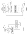
- FIG. 14 is a diagram illustrating a disk resource being accessed by a number of sources according to an embodiment of the system described herein.
- FIG. 15 is a diagram illustrating a disk resource with a resource queue and a number of source queues according to an embodiment of the system described herein.
- FIG. 16 is a flow chart illustrating processing performed in connection with initial calculation of a maximum queue depth according to an embodiment of the system described herein.
- FIG. 17 is a flow chart illustrating processing performed in connection with subsequent calculations of maximum queue depth according to an embodiment of the system described herein.
- FIG. 18 is a flow chart illustrating processing performed in connection with placement of service requests on different queues according to an embodiment of the system described herein.
- FIG. 19 is a flow chart illustrating processing performed in connection with moving service requests to a resource queue after the resource queue decreases in size according to an embodiment of the system described herein.
- FIG. 20 is a flow chart illustrating processing performed in connection with moving service requests to a resource queue after the requests become urgent according to an embodiment of the system described herein.
- a diagram 20 shows a plurality of hosts 22 a - 22 c coupled to a data storage device 24 .
- the data storage device 24 includes an internal memory 26 that facilitates operation of the storage device 24 as described elsewhere herein.
- the data storage device also includes a plurality of host adaptors (HA's) 28 a - 28 c that handle reading and writing of data between the hosts 22 a - 22 c and the storage device 24 .
- HA's host adaptors
- the storage device 24 may include one or more RDF adapter units (RA's) 32 a - 32 c .
- the RA's 32 a - 32 c are coupled to an RDF link 34 and are similar to the HA's 28 a - 28 c , but are used to transfer data between the storage device 24 and other storage devices (not shown in FIG. 1 ) that are also coupled to the RDF link 34 .
- the storage device 24 may be coupled to addition RDF links (not shown in FIG. 1 ) in addition to the RDF link 34 .
- the storage device 24 may also include one or more disks 36 a - 36 c , each containing a different portion of data stored on the storage device 24 .
- Each of the disks 36 a - 36 c may be coupled to a corresponding one of a plurality of disk adapter units (DA) 38 a - 38 c that provides data to a corresponding one of the disks 36 a - 36 c and receives data from a corresponding one of the disks 36 a - 36 c .
- DA disk adapter units
- the logical storage space in the storage device 24 that corresponds to the disks 36 a - 36 c may be subdivided into a plurality of volumes or logical devices.
- the logical devices may or may not correspond to the physical storage space of the disks 36 a - 36 c .
- the disk 36 a may contain a plurality of logical devices or, alternatively, a single logical device could span both of the disks 36 a , 36 b .
- the hosts 22 a - 22 c may be configured to access any combination of logical devices independent of the actual correspondence between the logical devices and the disks 36 a - 36 c.
- One or more internal logical data path(s) exist between the DA's 38 a - 38 c , the HA's 28 a - 28 c , the RA's 32 a - 32 c , and the memory 26 .
- one or more internal busses and/or communication modules may be used.
- the memory 26 may be used to facilitate data transferred between the DA's 38 a - 38 c , the HA's 28 a - 28 c and the RA's 32 a - 32 c .
- the memory 26 may contain tasks or requests that are to be performed by one or more of the DA's 38 a - 38 c , the HA's 28 a - 28 c and the RA's 32 a - 32 c , and a cache for data fetched from or pending write to one or more of the disks 36 a - 36 c . Use of the memory 26 is described in more detail hereinafter.
- the storage device 24 may be provided as a stand-alone device coupled to the hosts 22 a - 22 c as shown in FIG. 1 or, alternatively, the storage device 24 may be part of a storage area network (SAN) that includes a plurality of other storage devices as well as routers, network connections, etc.
- the storage device may be coupled to a SAN fabric and/or be part of a SAN fabric.
- the system described herein may be implemented using software, hardware, and/or a combination of software and hardware where software may be stored in an appropriate storage medium and executed by one or more processors.
- a diagram 50 illustrates an embodiment of the storage device 24 where each of a plurality of directors 52 a - 52 c are coupled to the memory 26 .
- Each of the directors 52 a - 52 c represents one of the HA's 28 a - 28 c , RA's 32 a - 32 c , or DA's 38 a - 38 c .
- the diagram 50 also shows an optional communication module (CM) 54 that provides an alternative communication path between the directors 52 a - 52 c .
- CM communication module
- Each of the directors 52 a - 52 c may be coupled to the CM 54 so that any one of the directors 52 a - 52 c may send a message and/or data to any other one of the directors 52 a - 52 c without needing to go through the memory 26 .
- the CM 54 may be implemented using conventional MUX/router technology where a sending one of the directors 52 a - 52 c provides an appropriate address to cause a message and/or data to be received by an intended receiving one of the directors 52 a - 52 c .
- CM 54 may be implemented using one or more of the directors 52 a - 52 c so that, for example, the directors 52 a - 52 c may be interconnected directly with the interconnection functionality being provided on each of the directors 52 a - 52 c .
- a sending one of the directors 52 a - 52 c may be able to broadcast a message to all of the other directors 52 a - 52 c at the same time.
- one or more of the directors 52 a - 52 c may have multiple processor systems thereon and thus may be able to perform functions for multiple directors. In some embodiments, at least one of the directors 52 a - 52 c having multiple processor systems thereon may simultaneously perform the functions of at least two different types of directors (e.g., an HA and a DA). Furthermore, in some embodiments, at least one of the directors 52 a - 52 c having multiple processor systems thereon may simultaneously perform the functions of at one types of director and perform other processing with the other processing system. In addition, all or at least part of the global memory 26 may be provided on one or more of the directors 52 a - 52 c and shared with other ones of the directors 52 a - 52 c.
- a diagram 70 illustrates a first storage device 72 coupled to a plurality of host devices 74 - 76 .
- the first storage device 72 is like the storage device 24 , described above, and the host devices 74 - 76 are like the hosts 22 a - 22 c , described above.
- the first storage device 72 may be coupled to a second storage device 78 by any appropriate means, including a connection through the Internet, a high-speed dedicated connection, a wireless or partially wireless connection, etc.
- the connection between the storage devices 72 , 78 may be like the RDF link 34 , discussed above.
- the host devices 74 - 76 may read and write data only from the first storage device 72 , which may then transfer some of the data to the second storage device 78 . In other embodiments, one or more of the host devices 74 - 76 may read and/or write data from and to the second storage device 78 through the first storage device 72 .
- a diagram 80 illustrates a plurality of computing devices 82 - 86 , some or all of which may be like the storage device 24 , discussed above.
- the computing devices 82 - 86 are interconnected so that, for example, the computing device 82 is coupled to the computing device 83 .
- some of the computing devices 82 - 86 may be coupled to each other indirectly through other computing devices.
- the computing device 82 communicates with the computing device 84 through the computing device 83 .
- a host device coupled to the computing device 82 intending to communicate with the computing device 84 would do so via the computing device 83 .
- One mechanism for facilitating such indirect communication is described in U.S. Pat. No. 6,697,367 titled MULTIHOP SYSTEM CALLS, which is incorporated by reference herein.
- one or more computing devices provides a service request to one or more other computing devices.
- a host device is providing a request to a storage device.
- a first storage device is providing a request to a second storage device.
- the internal components of the storage device 24 or other computing devices may also provide requests that are internal thereto so that, for example, the HA 28 a of the storage device 24 of FIG. 1 may provide a request to one of the DA's 38 a - 38 c of the storage device 24 .
- a diagram 100 illustrates a requester 102 that provides requests to a resource 104 that services the requests.
- the requester 102 may be any device or component that may provide requests to the resource 104 .
- the requester 102 may be a host device, a requesting component internal to the storage device 24 , or any other requesting component or device.
- the resource 104 represents any device or component capable of servicing the request provided by the requester 102 .
- the resource 104 may represent a storage device servicing requests from a host device or from another storage device.
- the requests may be I/O requests.
- the resource 104 may be managed by another component or device separate from the resource.
- the resource 104 may represent the memory 26 of the storage device 24 , which is managed by other processes within the storage device 24 so that a request for memory by the requester 102 is not handled directly by the memory 26 itself.
- references to the resource 104 should be understood to include both devices and components that service requests as well as devices or components that manage the resource 104 but are external to the resource 104 .
- the diagram 100 also includes a connection 106 for facilitating communication between the requester 102 and the resource 104 .
- the connection 106 may be any medium or mechanism used to communicate the request from the requester 102 to the resource 104 and/or used to provide results from the resource 104 to the requester 102 .
- the connection 106 may be, for example, any communication network, a direct connection, the Internet, an internal data bus of the storage device 24 , an ESCON or Fibre Channel connection, etc.
- a queue 120 may be maintained by the resource 104 or by an entity that controls the resource 104 to provide an ordered list of pending requests.
- the queue 120 may be implemented as a doubly linked list of elements 122 - 124 where each of the elements 122 - 124 represents a pending request (job) to be serviced using the resource 104 .
- Other appropriate ordering schema may be used, such as a heap.
- the queue 120 includes a start pointer that points to the first element 122 of the queue 120 .
- the request corresponding to the first element 122 is serviced.
- the first element 122 may be removed from the queue 120 and the start pointer may be adjusted to point to the next element 123 . Note that the details of servicing of the request depend on the type and nature of the resource as well as the type and nature of other related elements that handle servicing of the requests using the resource.
- any other appropriate data structure and/or mechanism may be used to maintain and manage ordering of pending requests. As explained in more detail elsewhere herein, it may be necessary in some instances to be able to insert elements in the middle of the ordered list of pending requests. Accordingly, solutions that employ arrays and/or tables that require moving a number of elements to perform such insertions may not be ideal.
- a diagram 130 shows one of the elements 122 - 124 of the queue 120 of FIG. 6 in more detail.
- the element includes a first pointer field 132 and a second pointer field 134 .
- the first pointer field 132 contains a pointer to a previous element of the queue 120 while the second pointer field 134 contains a pointer to the next element of the queue 120 .
- the first pointer field 132 contains a pointer to null for the first element 122 of the queue 120 and the second pointer field 134 contains a pointer to null for the last element 124 of the queue 120 .
- the diagram 130 also shows the element containing a time to become urgent (TBU) field 136 and a request description field 138 .
- TBU field 136 is used to determine ordering for the elements 122 - 124 of the queue 120 and is discussed in more detail elsewhere herein.
- the request description field 138 contains a description of the request provided by the requester 102 for the resource 104 .
- the request description field 138 may be provided in any appropriate format or protocol (including any conventional format or protocol) agreed upon by the requester 102 and the resource 104 .
- the resource 104 uses the request description field 138 to fulfill the request.
- the TBU that is associated with each of the elements 122 - 124 is provided by the requester 102 (or an agent associated with the requester 102 ) to indicate a specific time at which the request becomes an urgent request. Once a request has become urgent, the request may be given a higher priority by the resource 104 . As described in more detail elsewhere herein, in instances where multiple requests for the same resource have all become urgent, the requests may be fulfilled in an order corresponding to the most urgent first, the second most urgent second, etc. according to the value of the TBU parameter. Thus, the TBU parameter may be used as a mechanism to compare the relative urgency of requests.
- the value for the TBU parameter may be provided in units of absolute time (wall clock time) so that the TBU parameter indicates a specific time at which the associated request becomes urgent.
- wall clock time absolute time
- the requester 102 and the resource 104 are synchronized to the same wall clock time.
- the requester 102 may provide a relative time (e.g., relative to current time) which may be then translated by the resource 104 into absolute time or at least into the same type of time parameter used by the resource 104 .
- Providing such a relative time may not take into account an amount of time it takes for the request to travel from the requester 102 to the resource 104 .
- This travel time may be insignificant compared with the average response time of an I/O on a storage subsystem, but when the travel time is not is not insignificant, an adjustment that take into account the travel time can be made. For example, it is possible to add an empirically determined constant corresponding to an average time to send a request.
- the requester 102 may specify the TBU in other units, such as I/O cycles. Any appropriate units for TBU may be used provided that the units are understood by both the requester 102 and the resource 104 and/or may be converted to units understood by both the requester 102 and the resource 104 .
- a flowchart 160 illustrates steps performed by a resource in connection with receiving a request from a requester. Processing begins at a first step 162 where a pointer used to iterate through the queue of pending requests is made to point to the first element (most urgent) of the queue. Following the step 162 is a test step 164 which determines if the value for the TBU of the request being inserted is sooner (more urgent) than the TBU of the element pointed to by the pointer used to iterate through the queue. If so, then control transfers from the test step 164 to a step 166 where the request being added is inserted in the queue of pending requests at the location pointed to by the pointer. Following the step 166 , processing is complete.
- test step 164 determines whether the value for the TBU of the request being inserted is not sooner (more urgent) than the TBU of the element pointed to by the pointer. If it is determined that the test step 164 that the value for the TBU of the request being inserted is not sooner (more urgent) than the TBU of the element pointed to by the pointer, then control transfers from the test step 164 to a step 168 where the pointer is incremented to point to the next element of the queue. Following the step 168 is a test step 172 which determines if the pointer points past the end of the queue (i.e., if the entire queue has been traversed). If so, then control transfers from the test step 172 to the step 166 , discussed above, where the request is inserted. Note that if the step 166 is reached from the step 172 , then the new request is being inserted at the end of the queue. Following the step 166 , processing is complete.
- a single queue may be used by the resource 104 .
- a flowchart 180 illustrate steps performed in connection with determining whether to place a new request in an urgent queue or in a non-urgent queue. Processing begins at a first test step 182 where it is determined if the TBU associated with the new request has passed. If not, then control transfers to the step 184 where the new request is inserted into the non-urgent queue in a manner similar to that described above in connection with the flowchart 160 of FIG. 8 . Following step 184 , processing is complete.
- a flowchart 200 illustrates steps performed periodically to determine if a request in a non-urgent queue should be moved to an urgent queue. Note that this may occur as time passes since a request that was non-urgent when first placed in the non-urgent queue (see the flowchart 180 and the corresponding discussion above) may become urgent when the current time (wall time) corresponds to the TBU value associated with the request.
- Processing begins at a first step 202 where a pointer is set to point to the start of the queue used for non-urgent requests.
- the pointer set at the step 202 may be used to iterate through the requests in the non-urgent queue of requests.
- a test at 204 it is determined if the TBU for the request pointed to by the pointer has passed. If not, then processing is complete. Note that since the queue is ordered according to TBU values, then if the TBU has not passed for a particular element of the queue, the TBU has not passed for any additional elements beyond the particular element.
- a step 208 where the element is removed from the non-urgent queue. Note that removing the element at the step 208 may be performed using any appropriate technique, including conventional techniques used in connection with doubly linked lists and/or heaps.
- a step 212 where the pointer used to iterate through the non-urgent queue is incremented.
- a test step 214 where is determine if the pointer points past the end of the non-urgent queue (points to null). If so, then processing is complete. Otherwise, control transfers from the test step 214 back to the step 204 , discussed above.
- resources and/or entities that manage resources may not have a mechanism for handling an ordered list of requests. When this occurs, it may be useful for any requesters that provide requests that use such resources to have a mechanism for providing requests for such resources in an appropriate fashion.
- a policy that differentiates between requests that have become urgent for service and requests that have not become urgent for service to give priority to requests that have become urgent. It may be possible to have a global variable indicating the total number of pending requests (and/or pending request that have become urgent) for a resource. Requesters would examine the global variable and not provide requests and/or not provide non-urgent requests for the resource unless the global variable was below a predetermined threshold.
- a limit on the number of non-urgent requests may be enforced to ensure that urgent requests that arrive in the system latter will have a good response time from the resource.
- a limit on the utilization can be enforced. For example, it is possible to have a policy where a non-urgent request can not use space in the memory 26 if more than 50% of the memory is already in use, while an urgent request can allocate space in the memory 26 until the memory reaches the 75% mark (up to 75% in use).
- Another possibility for managing a resource is to move requests that require a resource which is not available (due to the policy) from a main queue and to a separate internal queue (waiting for the resource).
- the resource status changes e.g. the resource completes a request, or when the TBU arrives for the request moved to the internal queue, the request is moved back to the main queue.
- the resource that can not re-order requests according to the TBU is a bottleneck, the queue of non-urgent requests is limited and therefore the impact on the response time of urgent requests is bounded.
- a flowchart 220 illustrates steps performed by a requester in connection with determining whether to provide a request for a resource in a situation where the resource does not maintain an ordered list of pending requests. Processing begins at a first test step 222 where it is determined if the global variable used to monitor the requests provided to the resource is above a predetermined limit. If so, then processing transfers back to the step 222 to continue to poll the global variable until it is not below the predetermined limit.
- the processing illustrated by the flowchart 220 may be performed in connection with every new request or, alternatively, may be performed in connection with non-urgent requests only.
- the global variable may represent the total number of pending requests already provided to the resource. In other embodiments, the global variable may represent the total number of pending urgent requests provided to the resource. Note, however, that urgency may be determined at the time a request is provided to the resource and that, as discussed elsewhere herein, a pending request that is initially non-urgent may become urgent after enough time has passed.
- the global variable may be incremented at the step 224 by the requester to reflect that a new request has been added.
- the resource and/or an entity that manages the resource may increment the global variable.
- the global variable represents a number of non-urgent requests
- additional processing may traverse a list of pending requests searching for an urgent request that may be provided to the resource immediately even though a non-urgent may not.
- a flowchart 230 illustrates steps performed in connection with managing the global variable used in connection with providing requests for resource. It is possible for the resource and/or an entity that manages the resource to decrement the global verbal counter each time a request is satisfied. However, it is also possible for a separate process or entity, such as a requester, to manage the global variable.
- Processing for FIG. 12 begins at a first test step 232 which polls to wait for a signal from the resource (or related entity) indicating that a request (or an urgent request) has been serviced. Once it is determined at the test step 232 that a request has been serviced in connection with the resource, control transfers from the test step 232 to a step 234 where the global variable is decremented. Following the step 234 , control transfers back to the test step 232 .
- a resource may be a component, a device or, a portion thereof.
- a finite cache memory may be a resource.
- use of a resource like the cache memory may be conditioned on the type of request (urgent or non-urgent) that requests the resource.
- a cache slot may be provided in connection with an urgent request if the cache memory is 80% full or less but may be provided in connection with a non-urgent request only if the cache memory is 60% full or less. In such a case, when the cache memory is between 60% and 80% full, the granting of a cache slot to a request is conditioned upon whether the request is an urgent requests or a non-urgent request.
- a flowchart 250 illustrates conditioning granting of a resource on the state of urgency of a request. Processing begins at a first test step 252 where is determined if the request is urgent. If not, then control transfers from the test step 252 to a step 254 where a limit of N is used to determine whether the request can be satisfied or not. Following the step 254 , processing is complete.
- M and N may be different and maybe set such that an urgent request is more likely to be fulfilled or will be satisfied faster than a non-urgent request.
- the quality of service may be expressed in terms of I/O operations per second (IOSPS) and/or in an average response time (RT) corresponding to the time between an application initiating a disk write and the application receiving an acknowledgement.
- IOSPS I/O operations per second
- RT average response time
- a particular application or group of applications, user(s), sites, etc.
- the system described herein facilitates providing a specified (expected/desired) level of service.
- a diagram 300 shows a disk resource 302 and a plurality of sources 304 that request service (e.g. I/O's) from the disk resource 302 .
- Each of the sources 304 may correspond to an application, a group of applications, a user, a group of users, an organization, etc. that accesses the disk resource 302 and that may have an expected quality of service. Note that, although only three sources are shown in the diagram 300 , the sources 304 are meant to represent any number of sources, N.
- the system described herein is designed to provide, as nearly as possible, the expected quality of services associated to each of the sources 304 .
- a diagram 310 shows the disk resource 302 being accessed using a resource queue 312 .
- Each of the service requests i.e., I/O operations
- the number of items on the resource queue 312 is called the “queue depth”. Use of the queue depth of the resource queue 312 is described in more detail elsewhere herein.
- the diagram 310 also shows a plurality of source queues 314 - 316 , each of which corresponds to one of the sources 304 so that, for example, the source queue 314 may correspond to a source S1, the source queue 315 may correspond to a different source S2, etc.
- Each of the source queues 314 - 316 may contain pending service requests (I/O operations) for a corresponding one of the sources.
- a service request from a source may be provided directly to the resource queue 312 or may first be provided to a corresponding one of the source queues 314 - 316 . Under certain conditions, service requests may be moved from the source queues 314 - 316 to the resource queue 312 .
- the queues 312 , 314 - 316 may be provided using any appropriate mechanism/data structure, including, without limitation, an array, a linked list, etc.
- a flow chart 340 illustrates steps performed in connection with determining a max queue depth value.
- the max queue depth value may be used to determine whether to place service requests on the resource queue 312 or one of the source queues 314 - 316 and when to move service requests from one of the source queues 314 - 316 to the resource queue 312 .
- Processing begins at a step 342 where missing values for RTi are determined. For each source Si, the specified IOSPSi value is provided while RTi may or may not be provided.
- step 344 all of the IOSPSi values for all of the sources for the disk resource are added together to provide a value for IOSPS, the total of all of the requested I/O's per second from all the sources 304 that access the disk resource 302 .
- step 346 IOSPS is scaled to increase the likelihood that all of the sources will receive the requested IOSPSi and/or RTi.
- the value of IOSPS determined at the step 344 is multiplied by 1.6 at the step 346 , but other scaling factors may be used instead, including possibly scaling factors less than one.
- a table is consulted to find a queue depth and response time (RT) corresponding to the value of IOSPS determined at the steps 344 , 346 .
- a table is used that provides a plurality of entries that, for each queue depth of the resource queue 312 from one to sixty-four, indicate the corresponding IOSPS and RT. Note that, generally, as the queue depth increases, the corresponding values of IOSPS and RT also increase. Note also that it is possible to derive the table used at the step 348 using, for example, techniques taught in U.S. patent application Ser. No. 12/924,361, filed on Sep. 24, 2010 and titled: TECHNIQUES FOR MODELING DISK PERFORMANCE, which is incorporated by reference herein. Of course, other techniques may be used to provide the table used at the step 348 .
- a test step 352 where it is determined if the value of RT, determined at the step 348 using the table, is less than all values of RTi for all the sources 304 for the disk resource. That is, given the particular queue depth from the table, can all sources expect a response time less than the specified response time. If so, then control transfers from the test step 352 to a step 354 where the next entry in the table is examined. Each subsequent entry in the table corresponds to a queue depth one more than a previous entry. In the system described herein, it is desirable to determine the largest queue depth that still provides a specified response time RTi for all sources.
- the value of RT obtained at a second iteration corresponding to a queue depth of M is likely greater than a value of RT obtained in a first iteration corresponding to a queue depth of M ⁇ 1.
- the test step 352 where it is determined if the new RT is still less than all RTi values. If not, then control transfers from the test step 352 to a step 356 where the maximum queue depth variable is set to the table queue depth entry minus one.
- the maximum queue depth corresponds to a queue depth for the resource queue 312 that provides a response time for all sources that is less than the specified response time, RTi.
- a flow chart 370 illustrates processing that is performed periodically to adjust the value of max queue depth based on actual observed (measured) rates.
- the period of recalculation could be one minute, but other recalculation periods are also possible.
- Processing for the flow chart 370 begins at a first step 372 where the actual I/O's per second (iospsi) for source Si is determined.
- iospsi the actual I/O's per second
- One way to determine iospsi is to divide the observed qi (the queue depth provided by service requests from Si) by RTi, the expected response time.
- step 374 IOSPSi (specified I/O's per second) and iospsi (observed I/O's per second) are compared and the new value for IOSPSi is the minimum of the two. That is, IOSPSi ⁇ min(IOSPSi, iospsi). Note that the steps 372 , 374 may be repeated for all of the sources 304 , Si. Following the step 374 is a step 376 where the max queue depth is recalculated using, for example, the processing illustrated by the flow chart 340 , discussed above. After the step 376 , processing is complete.
- a flow chart 380 illustrates steps performed in connection with one of the sources, Si, generating a new request (I/O operation). Processing begins at a first step 381 where a value for LT (corresponding to the last time an I/O operation had been performed/requested for the source Si) is adjusted. If a significant amount of time has passed since a previous I/O operation, then the next I/O operation should be more likely to be deemed urgent (i.e., should become urgent sooner). For example, if a particular source has a TBU of 50 ms, and 100 ms has passed since a previous I/O operation, then the source has essentially missed an opportunity to perform an I/O operation.
- a step 382 where it is determined if the time since the last I/O operation for the source corresponds to a time to become urgent (TBUi) for the source Si.
- TBUi time to become urgent
- TBUi equals 1/IOSPSi, although other mechanisms may be used to determine/set TBUi.
- CT current time
- LT last time an I/O operation was performed
- control passes from the test step 382 to a step 384 where the service request (I/O operation) is placed directly onto the resource queue 312 .
- processing is complete.
- the actual depth of the resource queue 312 may be determined by subtracting the number of items that have been serviced from the number of items that have been provided to the queue 312 .
- Other appropriate techniques may be used instead to determine the depth of the resource queue 312 . Note also that, in some cases, it is possible to add items to the resource queue 312 but otherwise it may not be possible to control when or in what order items are ultimately serviced.
- a flow chart 390 illustrates processing performed in response to the size of the resource queue 312 decreasing after a service request (I/O operation) is completed by the disk resource 302 .
- Processing begins at a test step 392 where it is determined if the length of the resource queue 312 is less than max queue depth. If not, then processing is complete. Otherwise, control transfers from the test step 392 to a step 394 where an element from a source queue is moved from the source queue to the resource queue 312 . Following the step 394 , processing is complete.
- step 394 it could also be possible to transfer from the step 394 back to the step 392 and keep performing the loop containing the steps 392 , 394 until the test at the step 392 indicates that the resource queue 312 is not less than max queue depth. Also, in some embodiments, it is possible to examine the source queues 314 - 316 in a particular order, such as an order based on priority or an order based on the age of the oldest entry in each.
- a flow chart 400 illustrates steps performed periodically (e.g., once per millesecond) in connection with determining if any elements/entries on the source queues 314 - 316 have become urgent due to the passage of time and, if so, moving the (now urgent) entries to the resource queue 312 .
- periodic rates may be used.
- the interrupt could be set in response to an element being added to one of the source queues 314 - 316 for an amount of time corresponding to TBUi.
- Processing begins at a first step 402 where an iteration variable, i, is set to one.
- the iteration variable i may be used to iterate through all of the sources, Si.
- a test step 404 where it is determined if i is greater than N, the number of sources. If not, then control transfers from the test step 404 to a test step 406 where it is determined if the difference between the current time and the last time an I/O operation was performed for the source Si is greater than TBUi. If so, then control transfers from the test step 406 to a step 408 where the element from the source queue i is moved to the resource queue 312 .
- step 412 Following the step 408 is a step 412 where the index variable i is incremented. Note that the step 412 is also reached from the step 406 if (CT ⁇ LT) is not greater than TBUi. Following the step 412 , control transfers back to the step 404 , discussed above, for another iteration. Note that, if it is determined at the step 404 that i, the index variable, is greater than N, the number of sources, then control transfers back to the step 402 , discussed above, where i is reinitialized to iterate through all of the source queues again.
- the timer may be used to keep track of the actual passage of time (e.g., wall time).
- the timer may represent the number of seconds (or milliseconds, minutes, hours, etc.) since the system was initialized. Alternatively, the timer it may represent the actual time of day in combination with the date.
- the system described herein may be implemented using the hardware described herein, variations thereof, or any other appropriate hardware capable of providing the functionality described herein.
- one or more storage devices having components as described herein may, alone or in combination with other devices, provide an appropriate platform that executes any of the steps described herein.
- the system described herein includes computer software, in a non-transitory computer readable medium, that executes any of the steps described herein.
- the computer-readable storage medium may be located on at least one of the directors 52 a - 52 c.
Abstract
Description
LT=LT−½*max(0,LT−TBUi)
Note, by the way, that if LT−TBUi is less than zero (i.e., the last I/O operation was relatively recent), then LT is not adjusted.
Claims (20)
LT=LT−½*max(0,LT−TBUi).
LT=LT−½*max(0,LT−TBUi).
Priority Applications (1)
| Application Number | Priority Date | Filing Date | Title |
|---|---|---|---|
| US12/930,101 US8935490B1 (en) | 2010-12-28 | 2010-12-28 | Disk access quality of service |
Applications Claiming Priority (1)
| Application Number | Priority Date | Filing Date | Title |
|---|---|---|---|
| US12/930,101 US8935490B1 (en) | 2010-12-28 | 2010-12-28 | Disk access quality of service |
Publications (1)
| Publication Number | Publication Date |
|---|---|
| US8935490B1 true US8935490B1 (en) | 2015-01-13 |
Family
ID=52247886
Family Applications (1)
| Application Number | Title | Priority Date | Filing Date |
|---|---|---|---|
| US12/930,101 Active 2033-06-25 US8935490B1 (en) | 2010-12-28 | 2010-12-28 | Disk access quality of service |
Country Status (1)
| Country | Link |
|---|---|
| US (1) | US8935490B1 (en) |
Cited By (2)
| Publication number | Priority date | Publication date | Assignee | Title |
|---|---|---|---|---|
| US10466910B1 (en) | 2016-12-30 | 2019-11-05 | EMC IP Holding Company LLC | Dynamic resource partitioning |
| US11782851B2 (en) * | 2021-09-01 | 2023-10-10 | Micron Technology, Inc. | Dynamic queue depth adjustment |
Citations (6)
| Publication number | Priority date | Publication date | Assignee | Title |
|---|---|---|---|---|
| US5206939A (en) | 1990-09-24 | 1993-04-27 | Emc Corporation | System and method for disk mapping and data retrieval |
| US5778394A (en) | 1996-12-23 | 1998-07-07 | Emc Corporation | Space reclamation system and method for use in connection with tape logging system |
| US5845147A (en) | 1996-03-19 | 1998-12-01 | Emc Corporation | Single lock command for an I/O storage system that performs both locking and I/O data operation |
| US5857208A (en) | 1996-05-31 | 1999-01-05 | Emc Corporation | Method and apparatus for performing point in time backup operation in a computer system |
| US6697367B1 (en) | 2000-06-12 | 2004-02-24 | Emc Corporation | Multihop system calls |
| US7281086B1 (en) | 2005-06-02 | 2007-10-09 | Emc Corporation | Disk queue management for quality of service |
-
2010
- 2010-12-28 US US12/930,101 patent/US8935490B1/en active Active
Patent Citations (6)
| Publication number | Priority date | Publication date | Assignee | Title |
|---|---|---|---|---|
| US5206939A (en) | 1990-09-24 | 1993-04-27 | Emc Corporation | System and method for disk mapping and data retrieval |
| US5845147A (en) | 1996-03-19 | 1998-12-01 | Emc Corporation | Single lock command for an I/O storage system that performs both locking and I/O data operation |
| US5857208A (en) | 1996-05-31 | 1999-01-05 | Emc Corporation | Method and apparatus for performing point in time backup operation in a computer system |
| US5778394A (en) | 1996-12-23 | 1998-07-07 | Emc Corporation | Space reclamation system and method for use in connection with tape logging system |
| US6697367B1 (en) | 2000-06-12 | 2004-02-24 | Emc Corporation | Multihop system calls |
| US7281086B1 (en) | 2005-06-02 | 2007-10-09 | Emc Corporation | Disk queue management for quality of service |
Non-Patent Citations (1)
| Title |
|---|
| U.S. Appl. No. 12/924,361, filed Sep. 24, 2010, Marshak et al. |
Cited By (2)
| Publication number | Priority date | Publication date | Assignee | Title |
|---|---|---|---|---|
| US10466910B1 (en) | 2016-12-30 | 2019-11-05 | EMC IP Holding Company LLC | Dynamic resource partitioning |
| US11782851B2 (en) * | 2021-09-01 | 2023-10-10 | Micron Technology, Inc. | Dynamic queue depth adjustment |
Similar Documents
| Publication | Publication Date | Title |
|---|---|---|
| US9626309B1 (en) | Method and controller for requesting queue arbitration and coalescing memory access commands | |
| US7162550B2 (en) | Method, system, and program for managing requests to an Input/Output device | |
| US7840720B2 (en) | Using priority to determine whether to queue an input/output (I/O) request directed to storage | |
| US8892780B2 (en) | Management of shared storage I/O resources | |
| US7093256B2 (en) | Method and apparatus for scheduling real-time and non-real-time access to a shared resource | |
| US7016985B2 (en) | Method, system, and program for prioritizing input/output (I/O) requests submitted to a device driver | |
| US6353869B1 (en) | Adaptive delay of polling frequencies in a distributed system with a queued lock | |
| WO2021126295A1 (en) | Request throttling in distributed storage systems | |
| US8838849B1 (en) | Link sharing for multiple replication modes | |
| US8856400B1 (en) | I/O performance quotas | |
| US9176881B2 (en) | Computer system and storage control method | |
| US8516121B1 (en) | Method and apparatus for optimizing computer network usage to prevent congestion | |
| JP5894171B2 (en) | Arbitration of bus transactions on the communication bus and associated power management based on the health information of the bus device | |
| US8838916B2 (en) | Hybrid data storage management taking into account input/output (I/O) priority | |
| US10142211B2 (en) | Storage management device and control method | |
| JP2004520655A (en) | Resource selection in distributed computer systems. | |
| US6785792B2 (en) | Storage system and data relocation method | |
| US20140189277A1 (en) | Storage controller selecting system, storage controller selecting method, and recording medium | |
| US8261029B1 (en) | Dynamic balancing of writes between multiple storage devices | |
| US8935490B1 (en) | Disk access quality of service | |
| US7870335B2 (en) | Host adaptive seek technique environment | |
| US7890958B2 (en) | Automatic adjustment of time a consumer waits to access data from queue during a waiting phase and transmission phase at the queue | |
| US11481341B2 (en) | System and method for dynamically adjusting priority-based allocation of storage system resources | |
| US7155573B1 (en) | Cache fall through time estimation | |
| US10346054B1 (en) | Policy driven IO scheduler resilient to storage subsystem performance |
Legal Events
| Date | Code | Title | Description |
|---|---|---|---|
| AS | Assignment |
Owner name: EMC CORPORATION, MASSACHUSETTS Free format text: ASSIGNMENT OF ASSIGNORS INTEREST;ASSIGNORS:NAAMAD, AMNON;MORE, SACHIN;REEL/FRAME:025632/0515 Effective date: 20101227 |
|
| STCF | Information on status: patent grant |
Free format text: PATENTED CASE |
|
| CC | Certificate of correction | ||
| AS | Assignment |
Owner name: THE BANK OF NEW YORK MELLON TRUST COMPANY, N.A., AS NOTES COLLATERAL AGENT, TEXAS Free format text: SECURITY AGREEMENT;ASSIGNORS:ASAP SOFTWARE EXPRESS, INC.;AVENTAIL LLC;CREDANT TECHNOLOGIES, INC.;AND OTHERS;REEL/FRAME:040136/0001 Effective date: 20160907 Owner name: CREDIT SUISSE AG, CAYMAN ISLANDS BRANCH, AS COLLATERAL AGENT, NORTH CAROLINA Free format text: SECURITY AGREEMENT;ASSIGNORS:ASAP SOFTWARE EXPRESS, INC.;AVENTAIL LLC;CREDANT TECHNOLOGIES, INC.;AND OTHERS;REEL/FRAME:040134/0001 Effective date: 20160907 Owner name: CREDIT SUISSE AG, CAYMAN ISLANDS BRANCH, AS COLLAT Free format text: SECURITY AGREEMENT;ASSIGNORS:ASAP SOFTWARE EXPRESS, INC.;AVENTAIL LLC;CREDANT TECHNOLOGIES, INC.;AND OTHERS;REEL/FRAME:040134/0001 Effective date: 20160907 Owner name: THE BANK OF NEW YORK MELLON TRUST COMPANY, N.A., A Free format text: SECURITY AGREEMENT;ASSIGNORS:ASAP SOFTWARE EXPRESS, INC.;AVENTAIL LLC;CREDANT TECHNOLOGIES, INC.;AND OTHERS;REEL/FRAME:040136/0001 Effective date: 20160907 |
|
| AS | Assignment |
Owner name: EMC IP HOLDING COMPANY LLC, MASSACHUSETTS Free format text: ASSIGNMENT OF ASSIGNORS INTEREST;ASSIGNOR:EMC CORPORATION;REEL/FRAME:040203/0001 Effective date: 20160906 |
|
| MAFP | Maintenance fee payment |
Free format text: PAYMENT OF MAINTENANCE FEE, 4TH YEAR, LARGE ENTITY (ORIGINAL EVENT CODE: M1551) Year of fee payment: 4 |
|
| AS | Assignment |
Owner name: THE BANK OF NEW YORK MELLON TRUST COMPANY, N.A., T Free format text: SECURITY AGREEMENT;ASSIGNORS:CREDANT TECHNOLOGIES, INC.;DELL INTERNATIONAL L.L.C.;DELL MARKETING L.P.;AND OTHERS;REEL/FRAME:049452/0223 Effective date: 20190320 Owner name: THE BANK OF NEW YORK MELLON TRUST COMPANY, N.A., TEXAS Free format text: SECURITY AGREEMENT;ASSIGNORS:CREDANT TECHNOLOGIES, INC.;DELL INTERNATIONAL L.L.C.;DELL MARKETING L.P.;AND OTHERS;REEL/FRAME:049452/0223 Effective date: 20190320 |
|
| AS | Assignment |
Owner name: THE BANK OF NEW YORK MELLON TRUST COMPANY, N.A., TEXAS Free format text: SECURITY AGREEMENT;ASSIGNORS:CREDANT TECHNOLOGIES INC.;DELL INTERNATIONAL L.L.C.;DELL MARKETING L.P.;AND OTHERS;REEL/FRAME:053546/0001 Effective date: 20200409 |
|
| AS | Assignment |
Owner name: WYSE TECHNOLOGY L.L.C., CALIFORNIA Free format text: RELEASE BY SECURED PARTY;ASSIGNOR:CREDIT SUISSE AG, CAYMAN ISLANDS BRANCH;REEL/FRAME:058216/0001 Effective date: 20211101 Owner name: SCALEIO LLC, MASSACHUSETTS Free format text: RELEASE BY SECURED PARTY;ASSIGNOR:CREDIT SUISSE AG, CAYMAN ISLANDS BRANCH;REEL/FRAME:058216/0001 Effective date: 20211101 Owner name: MOZY, INC., WASHINGTON Free format text: RELEASE BY SECURED PARTY;ASSIGNOR:CREDIT SUISSE AG, CAYMAN ISLANDS BRANCH;REEL/FRAME:058216/0001 Effective date: 20211101 Owner name: MAGINATICS LLC, CALIFORNIA Free format text: RELEASE BY SECURED PARTY;ASSIGNOR:CREDIT SUISSE AG, CAYMAN ISLANDS BRANCH;REEL/FRAME:058216/0001 Effective date: 20211101 Owner name: FORCE10 NETWORKS, INC., CALIFORNIA Free format text: RELEASE BY SECURED PARTY;ASSIGNOR:CREDIT SUISSE AG, CAYMAN ISLANDS BRANCH;REEL/FRAME:058216/0001 Effective date: 20211101 Owner name: EMC IP HOLDING COMPANY LLC, TEXAS Free format text: RELEASE BY SECURED PARTY;ASSIGNOR:CREDIT SUISSE AG, CAYMAN ISLANDS BRANCH;REEL/FRAME:058216/0001 Effective date: 20211101 Owner name: EMC CORPORATION, MASSACHUSETTS Free format text: RELEASE BY SECURED PARTY;ASSIGNOR:CREDIT SUISSE AG, CAYMAN ISLANDS BRANCH;REEL/FRAME:058216/0001 Effective date: 20211101 Owner name: DELL SYSTEMS CORPORATION, TEXAS Free format text: RELEASE BY SECURED PARTY;ASSIGNOR:CREDIT SUISSE AG, CAYMAN ISLANDS BRANCH;REEL/FRAME:058216/0001 Effective date: 20211101 Owner name: DELL SOFTWARE INC., CALIFORNIA Free format text: RELEASE BY SECURED PARTY;ASSIGNOR:CREDIT SUISSE AG, CAYMAN ISLANDS BRANCH;REEL/FRAME:058216/0001 Effective date: 20211101 Owner name: DELL PRODUCTS L.P., TEXAS Free format text: RELEASE BY SECURED PARTY;ASSIGNOR:CREDIT SUISSE AG, CAYMAN ISLANDS BRANCH;REEL/FRAME:058216/0001 Effective date: 20211101 Owner name: DELL MARKETING L.P., TEXAS Free format text: RELEASE BY SECURED PARTY;ASSIGNOR:CREDIT SUISSE AG, CAYMAN ISLANDS BRANCH;REEL/FRAME:058216/0001 Effective date: 20211101 Owner name: DELL INTERNATIONAL, L.L.C., TEXAS Free format text: RELEASE BY SECURED PARTY;ASSIGNOR:CREDIT SUISSE AG, CAYMAN ISLANDS BRANCH;REEL/FRAME:058216/0001 Effective date: 20211101 Owner name: DELL USA L.P., TEXAS Free format text: RELEASE BY SECURED PARTY;ASSIGNOR:CREDIT SUISSE AG, CAYMAN ISLANDS BRANCH;REEL/FRAME:058216/0001 Effective date: 20211101 Owner name: CREDANT TECHNOLOGIES, INC., TEXAS Free format text: RELEASE BY SECURED PARTY;ASSIGNOR:CREDIT SUISSE AG, CAYMAN ISLANDS BRANCH;REEL/FRAME:058216/0001 Effective date: 20211101 Owner name: AVENTAIL LLC, CALIFORNIA Free format text: RELEASE BY SECURED PARTY;ASSIGNOR:CREDIT SUISSE AG, CAYMAN ISLANDS BRANCH;REEL/FRAME:058216/0001 Effective date: 20211101 Owner name: ASAP SOFTWARE EXPRESS, INC., ILLINOIS Free format text: RELEASE BY SECURED PARTY;ASSIGNOR:CREDIT SUISSE AG, CAYMAN ISLANDS BRANCH;REEL/FRAME:058216/0001 Effective date: 20211101 |
|
| AS | Assignment |
Owner name: SCALEIO LLC, MASSACHUSETTS Free format text: RELEASE OF SECURITY INTEREST IN PATENTS PREVIOUSLY RECORDED AT REEL/FRAME (040136/0001);ASSIGNOR:THE BANK OF NEW YORK MELLON TRUST COMPANY, N.A., AS NOTES COLLATERAL AGENT;REEL/FRAME:061324/0001 Effective date: 20220329 Owner name: EMC IP HOLDING COMPANY LLC (ON BEHALF OF ITSELF AND AS SUCCESSOR-IN-INTEREST TO MOZY, INC.), TEXAS Free format text: RELEASE OF SECURITY INTEREST IN PATENTS PREVIOUSLY RECORDED AT REEL/FRAME (040136/0001);ASSIGNOR:THE BANK OF NEW YORK MELLON TRUST COMPANY, N.A., AS NOTES COLLATERAL AGENT;REEL/FRAME:061324/0001 Effective date: 20220329 Owner name: EMC CORPORATION (ON BEHALF OF ITSELF AND AS SUCCESSOR-IN-INTEREST TO MAGINATICS LLC), MASSACHUSETTS Free format text: RELEASE OF SECURITY INTEREST IN PATENTS PREVIOUSLY RECORDED AT REEL/FRAME (040136/0001);ASSIGNOR:THE BANK OF NEW YORK MELLON TRUST COMPANY, N.A., AS NOTES COLLATERAL AGENT;REEL/FRAME:061324/0001 Effective date: 20220329 Owner name: DELL MARKETING CORPORATION (SUCCESSOR-IN-INTEREST TO FORCE10 NETWORKS, INC. AND WYSE TECHNOLOGY L.L.C.), TEXAS Free format text: RELEASE OF SECURITY INTEREST IN PATENTS PREVIOUSLY RECORDED AT REEL/FRAME (040136/0001);ASSIGNOR:THE BANK OF NEW YORK MELLON TRUST COMPANY, N.A., AS NOTES COLLATERAL AGENT;REEL/FRAME:061324/0001 Effective date: 20220329 Owner name: DELL PRODUCTS L.P., TEXAS Free format text: RELEASE OF SECURITY INTEREST IN PATENTS PREVIOUSLY RECORDED AT REEL/FRAME (040136/0001);ASSIGNOR:THE BANK OF NEW YORK MELLON TRUST COMPANY, N.A., AS NOTES COLLATERAL AGENT;REEL/FRAME:061324/0001 Effective date: 20220329 Owner name: DELL INTERNATIONAL L.L.C., TEXAS Free format text: RELEASE OF SECURITY INTEREST IN PATENTS PREVIOUSLY RECORDED AT REEL/FRAME (040136/0001);ASSIGNOR:THE BANK OF NEW YORK MELLON TRUST COMPANY, N.A., AS NOTES COLLATERAL AGENT;REEL/FRAME:061324/0001 Effective date: 20220329 Owner name: DELL USA L.P., TEXAS Free format text: RELEASE OF SECURITY INTEREST IN PATENTS PREVIOUSLY RECORDED AT REEL/FRAME (040136/0001);ASSIGNOR:THE BANK OF NEW YORK MELLON TRUST COMPANY, N.A., AS NOTES COLLATERAL AGENT;REEL/FRAME:061324/0001 Effective date: 20220329 Owner name: DELL MARKETING L.P. (ON BEHALF OF ITSELF AND AS SUCCESSOR-IN-INTEREST TO CREDANT TECHNOLOGIES, INC.), TEXAS Free format text: RELEASE OF SECURITY INTEREST IN PATENTS PREVIOUSLY RECORDED AT REEL/FRAME (040136/0001);ASSIGNOR:THE BANK OF NEW YORK MELLON TRUST COMPANY, N.A., AS NOTES COLLATERAL AGENT;REEL/FRAME:061324/0001 Effective date: 20220329 Owner name: DELL MARKETING CORPORATION (SUCCESSOR-IN-INTEREST TO ASAP SOFTWARE EXPRESS, INC.), TEXAS Free format text: RELEASE OF SECURITY INTEREST IN PATENTS PREVIOUSLY RECORDED AT REEL/FRAME (040136/0001);ASSIGNOR:THE BANK OF NEW YORK MELLON TRUST COMPANY, N.A., AS NOTES COLLATERAL AGENT;REEL/FRAME:061324/0001 Effective date: 20220329 |
|
| AS | Assignment |
Owner name: SCALEIO LLC, MASSACHUSETTS Free format text: RELEASE OF SECURITY INTEREST IN PATENTS PREVIOUSLY RECORDED AT REEL/FRAME (045455/0001);ASSIGNOR:THE BANK OF NEW YORK MELLON TRUST COMPANY, N.A., AS NOTES COLLATERAL AGENT;REEL/FRAME:061753/0001 Effective date: 20220329 Owner name: EMC IP HOLDING COMPANY LLC (ON BEHALF OF ITSELF AND AS SUCCESSOR-IN-INTEREST TO MOZY, INC.), TEXAS Free format text: RELEASE OF SECURITY INTEREST IN PATENTS PREVIOUSLY RECORDED AT REEL/FRAME (045455/0001);ASSIGNOR:THE BANK OF NEW YORK MELLON TRUST COMPANY, N.A., AS NOTES COLLATERAL AGENT;REEL/FRAME:061753/0001 Effective date: 20220329 Owner name: EMC CORPORATION (ON BEHALF OF ITSELF AND AS SUCCESSOR-IN-INTEREST TO MAGINATICS LLC), MASSACHUSETTS Free format text: RELEASE OF SECURITY INTEREST IN PATENTS PREVIOUSLY RECORDED AT REEL/FRAME (045455/0001);ASSIGNOR:THE BANK OF NEW YORK MELLON TRUST COMPANY, N.A., AS NOTES COLLATERAL AGENT;REEL/FRAME:061753/0001 Effective date: 20220329 Owner name: DELL MARKETING CORPORATION (SUCCESSOR-IN-INTEREST TO FORCE10 NETWORKS, INC. AND WYSE TECHNOLOGY L.L.C.), TEXAS Free format text: RELEASE OF SECURITY INTEREST IN PATENTS PREVIOUSLY RECORDED AT REEL/FRAME (045455/0001);ASSIGNOR:THE BANK OF NEW YORK MELLON TRUST COMPANY, N.A., AS NOTES COLLATERAL AGENT;REEL/FRAME:061753/0001 Effective date: 20220329 Owner name: DELL PRODUCTS L.P., TEXAS Free format text: RELEASE OF SECURITY INTEREST IN PATENTS PREVIOUSLY RECORDED AT REEL/FRAME (045455/0001);ASSIGNOR:THE BANK OF NEW YORK MELLON TRUST COMPANY, N.A., AS NOTES COLLATERAL AGENT;REEL/FRAME:061753/0001 Effective date: 20220329 Owner name: DELL INTERNATIONAL L.L.C., TEXAS Free format text: RELEASE OF SECURITY INTEREST IN PATENTS PREVIOUSLY RECORDED AT REEL/FRAME (045455/0001);ASSIGNOR:THE BANK OF NEW YORK MELLON TRUST COMPANY, N.A., AS NOTES COLLATERAL AGENT;REEL/FRAME:061753/0001 Effective date: 20220329 Owner name: DELL USA L.P., TEXAS Free format text: RELEASE OF SECURITY INTEREST IN PATENTS PREVIOUSLY RECORDED AT REEL/FRAME (045455/0001);ASSIGNOR:THE BANK OF NEW YORK MELLON TRUST COMPANY, N.A., AS NOTES COLLATERAL AGENT;REEL/FRAME:061753/0001 Effective date: 20220329 Owner name: DELL MARKETING L.P. (ON BEHALF OF ITSELF AND AS SUCCESSOR-IN-INTEREST TO CREDANT TECHNOLOGIES, INC.), TEXAS Free format text: RELEASE OF SECURITY INTEREST IN PATENTS PREVIOUSLY RECORDED AT REEL/FRAME (045455/0001);ASSIGNOR:THE BANK OF NEW YORK MELLON TRUST COMPANY, N.A., AS NOTES COLLATERAL AGENT;REEL/FRAME:061753/0001 Effective date: 20220329 Owner name: DELL MARKETING CORPORATION (SUCCESSOR-IN-INTEREST TO ASAP SOFTWARE EXPRESS, INC.), TEXAS Free format text: RELEASE OF SECURITY INTEREST IN PATENTS PREVIOUSLY RECORDED AT REEL/FRAME (045455/0001);ASSIGNOR:THE BANK OF NEW YORK MELLON TRUST COMPANY, N.A., AS NOTES COLLATERAL AGENT;REEL/FRAME:061753/0001 Effective date: 20220329 |
|
| MAFP | Maintenance fee payment |
Free format text: PAYMENT OF MAINTENANCE FEE, 8TH YEAR, LARGE ENTITY (ORIGINAL EVENT CODE: M1552); ENTITY STATUS OF PATENT OWNER: LARGE ENTITY Year of fee payment: 8 |