US8930019B2 - Mobile human interface robot - Google Patents
Mobile human interface robot Download PDFInfo
- Publication number
- US8930019B2 US8930019B2 US13/241,765 US201113241765A US8930019B2 US 8930019 B2 US8930019 B2 US 8930019B2 US 201113241765 A US201113241765 A US 201113241765A US 8930019 B2 US8930019 B2 US 8930019B2
- Authority
- US
- United States
- Prior art keywords
- robot
- processing unit
- map
- controller
- general purpose
- Prior art date
- Legal status (The legal status is an assumption and is not a legal conclusion. Google has not performed a legal analysis and makes no representation as to the accuracy of the status listed.)
- Active, expires
Links
- 238000012545 processing Methods 0.000 claims abstract description 110
- 238000004891 communication Methods 0.000 claims abstract description 67
- 238000000034 method Methods 0.000 claims description 100
- 238000003384 imaging method Methods 0.000 claims description 65
- 230000033001 locomotion Effects 0.000 claims description 43
- 238000013507 mapping Methods 0.000 claims description 12
- 230000008569 process Effects 0.000 claims description 12
- 238000011156 evaluation Methods 0.000 claims description 10
- 238000013519 translation Methods 0.000 claims description 10
- 239000013598 vector Substances 0.000 claims description 10
- 230000008859 change Effects 0.000 claims description 9
- 238000004091 panning Methods 0.000 claims description 8
- PXFBZOLANLWPMH-UHFFFAOYSA-N 16-Epiaffinine Natural products C1C(C2=CC=CC=C2N2)=C2C(=O)CC2C(=CC)CN(C)C1C2CO PXFBZOLANLWPMH-UHFFFAOYSA-N 0.000 claims description 5
- 230000009466 transformation Effects 0.000 claims description 4
- 230000006399 behavior Effects 0.000 description 67
- 230000000875 corresponding effect Effects 0.000 description 61
- 230000009471 action Effects 0.000 description 33
- 238000001514 detection method Methods 0.000 description 32
- 238000004590 computer program Methods 0.000 description 13
- 238000005096 rolling process Methods 0.000 description 11
- 230000006870 function Effects 0.000 description 9
- 230000005484 gravity Effects 0.000 description 9
- 238000001125 extrusion Methods 0.000 description 8
- 230000004044 response Effects 0.000 description 8
- 230000014616 translation Effects 0.000 description 8
- 230000003287 optical effect Effects 0.000 description 7
- 230000000007 visual effect Effects 0.000 description 7
- 230000001133 acceleration Effects 0.000 description 5
- 230000001276 controlling effect Effects 0.000 description 5
- 230000002441 reversible effect Effects 0.000 description 5
- 210000003813 thumb Anatomy 0.000 description 5
- 230000003542 behavioural effect Effects 0.000 description 4
- 230000008901 benefit Effects 0.000 description 4
- 230000005540 biological transmission Effects 0.000 description 4
- 238000003708 edge detection Methods 0.000 description 4
- 230000003993 interaction Effects 0.000 description 4
- 230000002688 persistence Effects 0.000 description 4
- 230000002829 reductive effect Effects 0.000 description 4
- 230000001953 sensory effect Effects 0.000 description 4
- 238000003860 storage Methods 0.000 description 4
- 241000282412 Homo Species 0.000 description 3
- 238000013475 authorization Methods 0.000 description 3
- 238000004422 calculation algorithm Methods 0.000 description 3
- 238000004364 calculation method Methods 0.000 description 3
- 230000009194 climbing Effects 0.000 description 3
- 230000006835 compression Effects 0.000 description 3
- 238000007906 compression Methods 0.000 description 3
- 238000013461 design Methods 0.000 description 3
- 238000005562 fading Methods 0.000 description 3
- 230000000977 initiatory effect Effects 0.000 description 3
- 230000002452 interceptive effect Effects 0.000 description 3
- 238000012546 transfer Methods 0.000 description 3
- 230000007704 transition Effects 0.000 description 3
- 239000000872 buffer Substances 0.000 description 2
- 238000005516 engineering process Methods 0.000 description 2
- 230000001815 facial effect Effects 0.000 description 2
- 238000005286 illumination Methods 0.000 description 2
- 238000007726 management method Methods 0.000 description 2
- 238000005259 measurement Methods 0.000 description 2
- 238000012986 modification Methods 0.000 description 2
- 230000004048 modification Effects 0.000 description 2
- 238000012544 monitoring process Methods 0.000 description 2
- 230000000644 propagated effect Effects 0.000 description 2
- 230000009467 reduction Effects 0.000 description 2
- 238000013515 script Methods 0.000 description 2
- 238000007789 sealing Methods 0.000 description 2
- 239000004065 semiconductor Substances 0.000 description 2
- 238000000926 separation method Methods 0.000 description 2
- 238000012360 testing method Methods 0.000 description 2
- 238000012935 Averaging Methods 0.000 description 1
- 230000003044 adaptive effect Effects 0.000 description 1
- 238000013459 approach Methods 0.000 description 1
- 230000003139 buffering effect Effects 0.000 description 1
- 238000006243 chemical reaction Methods 0.000 description 1
- 238000012937 correction Methods 0.000 description 1
- 230000003247 decreasing effect Effects 0.000 description 1
- 238000006073 displacement reaction Methods 0.000 description 1
- 238000009826 distribution Methods 0.000 description 1
- 229940079593 drug Drugs 0.000 description 1
- 239000003814 drug Substances 0.000 description 1
- 239000000428 dust Substances 0.000 description 1
- 230000000694 effects Effects 0.000 description 1
- 230000003203 everyday effect Effects 0.000 description 1
- 230000010354 integration Effects 0.000 description 1
- 230000000670 limiting effect Effects 0.000 description 1
- 230000004807 localization Effects 0.000 description 1
- 230000007774 longterm Effects 0.000 description 1
- 239000011159 matrix material Substances 0.000 description 1
- 230000007246 mechanism Effects 0.000 description 1
- 230000000474 nursing effect Effects 0.000 description 1
- 238000012856 packing Methods 0.000 description 1
- 230000036961 partial effect Effects 0.000 description 1
- 238000003909 pattern recognition Methods 0.000 description 1
- 230000008447 perception Effects 0.000 description 1
- 230000002093 peripheral effect Effects 0.000 description 1
- 230000000704 physical effect Effects 0.000 description 1
- 238000012913 prioritisation Methods 0.000 description 1
- 238000002310 reflectometry Methods 0.000 description 1
- 238000009877 rendering Methods 0.000 description 1
- 230000011664 signaling Effects 0.000 description 1
- 239000002356 single layer Substances 0.000 description 1
- 230000003595 spectral effect Effects 0.000 description 1
- 239000000758 substrate Substances 0.000 description 1
- 230000002123 temporal effect Effects 0.000 description 1
- 238000012549 training Methods 0.000 description 1
- 238000002604 ultrasonography Methods 0.000 description 1
- 238000010407 vacuum cleaning Methods 0.000 description 1
- XLYOFNOQVPJJNP-UHFFFAOYSA-N water Substances O XLYOFNOQVPJJNP-UHFFFAOYSA-N 0.000 description 1
Images


Classifications
-
- G—PHYSICS
- G05—CONTROLLING; REGULATING
- G05D—SYSTEMS FOR CONTROLLING OR REGULATING NON-ELECTRIC VARIABLES
- G05D1/00—Control of position, course or altitude of land, water, air, or space vehicles, e.g. automatic pilot
- G05D1/02—Control of position or course in two dimensions
- G05D1/021—Control of position or course in two dimensions specially adapted to land vehicles
- G05D1/0231—Control of position or course in two dimensions specially adapted to land vehicles using optical position detecting means
- G05D1/0246—Control of position or course in two dimensions specially adapted to land vehicles using optical position detecting means using a video camera in combination with image processing means
- G05D1/0248—Control of position or course in two dimensions specially adapted to land vehicles using optical position detecting means using a video camera in combination with image processing means in combination with a laser
-
- B—PERFORMING OPERATIONS; TRANSPORTING
- B25—HAND TOOLS; PORTABLE POWER-DRIVEN TOOLS; MANIPULATORS
- B25J—MANIPULATORS; CHAMBERS PROVIDED WITH MANIPULATION DEVICES
- B25J11/00—Manipulators not otherwise provided for
- B25J11/008—Manipulators for service tasks
-
- B—PERFORMING OPERATIONS; TRANSPORTING
- B25—HAND TOOLS; PORTABLE POWER-DRIVEN TOOLS; MANIPULATORS
- B25J—MANIPULATORS; CHAMBERS PROVIDED WITH MANIPULATION DEVICES
- B25J13/00—Controls for manipulators
- B25J13/006—Controls for manipulators by means of a wireless system for controlling one or several manipulators
-
- B—PERFORMING OPERATIONS; TRANSPORTING
- B25—HAND TOOLS; PORTABLE POWER-DRIVEN TOOLS; MANIPULATORS
- B25J—MANIPULATORS; CHAMBERS PROVIDED WITH MANIPULATION DEVICES
- B25J13/00—Controls for manipulators
- B25J13/06—Control stands, e.g. consoles, switchboards
-
- B—PERFORMING OPERATIONS; TRANSPORTING
- B25—HAND TOOLS; PORTABLE POWER-DRIVEN TOOLS; MANIPULATORS
- B25J—MANIPULATORS; CHAMBERS PROVIDED WITH MANIPULATION DEVICES
- B25J19/00—Accessories fitted to manipulators, e.g. for monitoring, for viewing; Safety devices combined with or specially adapted for use in connection with manipulators
- B25J19/02—Sensing devices
- B25J19/021—Optical sensing devices
- B25J19/023—Optical sensing devices including video camera means
-
- B—PERFORMING OPERATIONS; TRANSPORTING
- B25—HAND TOOLS; PORTABLE POWER-DRIVEN TOOLS; MANIPULATORS
- B25J—MANIPULATORS; CHAMBERS PROVIDED WITH MANIPULATION DEVICES
- B25J5/00—Manipulators mounted on wheels or on carriages
- B25J5/007—Manipulators mounted on wheels or on carriages mounted on wheels
-
- B—PERFORMING OPERATIONS; TRANSPORTING
- B25—HAND TOOLS; PORTABLE POWER-DRIVEN TOOLS; MANIPULATORS
- B25J—MANIPULATORS; CHAMBERS PROVIDED WITH MANIPULATION DEVICES
- B25J9/00—Programme-controlled manipulators
- B25J9/0003—Home robots, i.e. small robots for domestic use
-
- G—PHYSICS
- G05—CONTROLLING; REGULATING
- G05D—SYSTEMS FOR CONTROLLING OR REGULATING NON-ELECTRIC VARIABLES
- G05D1/00—Control of position, course or altitude of land, water, air, or space vehicles, e.g. automatic pilot
- G05D1/02—Control of position or course in two dimensions
- G05D1/021—Control of position or course in two dimensions specially adapted to land vehicles
- G05D1/0268—Control of position or course in two dimensions specially adapted to land vehicles using internal positioning means
- G05D1/0274—Control of position or course in two dimensions specially adapted to land vehicles using internal positioning means using mapping information stored in a memory device
-
- G—PHYSICS
- G06—COMPUTING; CALCULATING OR COUNTING
- G06F—ELECTRIC DIGITAL DATA PROCESSING
- G06F1/00—Details not covered by groups G06F3/00 - G06F13/00 and G06F21/00
- G06F1/16—Constructional details or arrangements
- G06F1/1613—Constructional details or arrangements for portable computers
- G06F1/1632—External expansion units, e.g. docking stations
-
- G—PHYSICS
- G05—CONTROLLING; REGULATING
- G05D—SYSTEMS FOR CONTROLLING OR REGULATING NON-ELECTRIC VARIABLES
- G05D1/00—Control of position, course or altitude of land, water, air, or space vehicles, e.g. automatic pilot
- G05D1/02—Control of position or course in two dimensions
- G05D1/021—Control of position or course in two dimensions specially adapted to land vehicles
- G05D1/0231—Control of position or course in two dimensions specially adapted to land vehicles using optical position detecting means
- G05D1/0238—Control of position or course in two dimensions specially adapted to land vehicles using optical position detecting means using obstacle or wall sensors
- G05D1/024—Control of position or course in two dimensions specially adapted to land vehicles using optical position detecting means using obstacle or wall sensors in combination with a laser
-
- G—PHYSICS
- G05—CONTROLLING; REGULATING
- G05D—SYSTEMS FOR CONTROLLING OR REGULATING NON-ELECTRIC VARIABLES
- G05D1/00—Control of position, course or altitude of land, water, air, or space vehicles, e.g. automatic pilot
- G05D1/02—Control of position or course in two dimensions
- G05D1/021—Control of position or course in two dimensions specially adapted to land vehicles
- G05D1/0231—Control of position or course in two dimensions specially adapted to land vehicles using optical position detecting means
- G05D1/0246—Control of position or course in two dimensions specially adapted to land vehicles using optical position detecting means using a video camera in combination with image processing means
- G05D1/0253—Control of position or course in two dimensions specially adapted to land vehicles using optical position detecting means using a video camera in combination with image processing means extracting relative motion information from a plurality of images taken successively, e.g. visual odometry, optical flow
-
- G—PHYSICS
- G05—CONTROLLING; REGULATING
- G05D—SYSTEMS FOR CONTROLLING OR REGULATING NON-ELECTRIC VARIABLES
- G05D1/00—Control of position, course or altitude of land, water, air, or space vehicles, e.g. automatic pilot
- G05D1/02—Control of position or course in two dimensions
- G05D1/021—Control of position or course in two dimensions specially adapted to land vehicles
- G05D1/0255—Control of position or course in two dimensions specially adapted to land vehicles using acoustic signals, e.g. ultra-sonic singals
-
- G—PHYSICS
- G05—CONTROLLING; REGULATING
- G05D—SYSTEMS FOR CONTROLLING OR REGULATING NON-ELECTRIC VARIABLES
- G05D1/00—Control of position, course or altitude of land, water, air, or space vehicles, e.g. automatic pilot
- G05D1/02—Control of position or course in two dimensions
- G05D1/021—Control of position or course in two dimensions specially adapted to land vehicles
- G05D1/0268—Control of position or course in two dimensions specially adapted to land vehicles using internal positioning means
- G05D1/027—Control of position or course in two dimensions specially adapted to land vehicles using internal positioning means comprising intertial navigation means, e.g. azimuth detector
-
- G—PHYSICS
- G05—CONTROLLING; REGULATING
- G05D—SYSTEMS FOR CONTROLLING OR REGULATING NON-ELECTRIC VARIABLES
- G05D1/00—Control of position, course or altitude of land, water, air, or space vehicles, e.g. automatic pilot
- G05D1/02—Control of position or course in two dimensions
- G05D1/021—Control of position or course in two dimensions specially adapted to land vehicles
- G05D1/0268—Control of position or course in two dimensions specially adapted to land vehicles using internal positioning means
- G05D1/0272—Control of position or course in two dimensions specially adapted to land vehicles using internal positioning means comprising means for registering the travel distance, e.g. revolutions of wheels
-
- G—PHYSICS
- G05—CONTROLLING; REGULATING
- G05D—SYSTEMS FOR CONTROLLING OR REGULATING NON-ELECTRIC VARIABLES
- G05D2201/00—Application
- G05D2201/02—Control of position of land vehicles
- G05D2201/0206—Vehicle in a health care environment, e.g. for distribution of food or medicins in a hospital or for helping handicapped persons
-
- G—PHYSICS
- G05—CONTROLLING; REGULATING
- G05D—SYSTEMS FOR CONTROLLING OR REGULATING NON-ELECTRIC VARIABLES
- G05D2201/00—Application
- G05D2201/02—Control of position of land vehicles
- G05D2201/0211—Vehicle in an office environment, e.g. for delivering mail or for videoconferencing
Definitions
- This disclosure relates to mobile human interface robots.
- a robot is generally an electro-mechanical machine guided by a computer or electronic programming.
- Mobile robots have the capability to move around in their environment and are not fixed to one physical location.
- An example of a mobile robot that is in common use today is an automated guided vehicle or automatic guided vehicle (AGV).
- An AGV is generally a mobile robot that follows markers or wires in the floor, or uses a vision system or lasers for navigation.
- Mobile robots can be found in industry, military and security environments. They also appear as consumer products, for entertainment or to perform certain tasks like vacuum cleaning and home assistance.
- a mobile human interface robot that includes a drive system, a controller in communication with the dive system, and an electronic display supported above the drive system and in communication with the controller.
- the controller includes a central processing unit, a general purpose graphics processing unit, and memory in electrical communication with the central processing unit and the general purpose graphics processing unit.
- the controller has a display operating state and a driving operating state.
- the controller executes graphics computations on the general purpose graphics processing unit for displaying graphics on the electronic display during the display operating state; and the controller executes mobility computations on the general purpose graphics processing unit for issuing commands to the drive system during the driving operating state.
- the controller may operate in both the display operating state and the driving operating state simultaneously.
- the central processing unit can process more than about 1000 million instructions per second (MIPS).
- the electronic display may be a tablet computer in wireless communication with the controller, detachably supported above the drive system, and optionally movable with at least one degree of freedom while attached to the robot.
- the tablet computer comprises a touch screen having a display area of at least 150 square inches.
- the mobile human interface robot may include a display in electric communication with the controller and arranged to detachably receive the tablet computer there over. The display has an inactive state when the tablet computer is received over the display and an active state when the tablet computer is detached from the display.
- the mobile human interface robot includes a camera supported above the drive system and movable within at least one degree of freedom separately from the display.
- the camera may be a volumetric point cloud imaging device positioned to be capable of obtaining a point cloud from a volume of space adjacent the robot.
- the camera can be movable to view an area proximate a front edge of the robot.
- the mobile human interface robot includes a volumetric point cloud imaging device positioned at a height of greater than 1 or 2 feet above a ground surface and directed to be capable of obtaining a point cloud from a volume of space that includes a floor plane in a direction of movement of the robot.
- the drive system may be a holonomic drive system having first, second, and third driven drive wheels.
- Each drive wheel is trilaterally spaced about a vertical center axis of the base and each has a drive direction perpendicular to a radial axis with respect to the vertical center axis.
- the robot may include a base defining a vertical center axis and supporting the controller, an extendable leg extending upward from the base, and a torso supported by the leg. Actuation of the leg causes a change in elevation of the torso.
- the electronic display can be supported above the torso.
- the robot includes a neck supported by the torso and a head supported by the neck. The neck is capable of panning and tilting the head with respect to the torso.
- the head electronic can detachably support the display.
- a mobile human interface robot that includes a drive system, a controller in communication with the dive system, and a portable computing device detachably supported above the drive system and in wireless communication with the controller.
- the portable computing device includes a central processing unit, a general purpose graphics processing unit, and memory in electrical communication with the central processing unit and the general purpose graphics processing unit.
- the portable computing device executes graphics computations on the general purpose graphics processing unit for displaying graphics on an electronic display.
- the portable computing device executes mobility computations on the general purpose graphics processing unit.
- the controller issues drive commands to the drive system based on the mobility computations.
- the central processing unit can process more than about 1000 million instructions per second (MIPS).
- the electronic display may be a tablet computer in wireless communication with the controller, detachably supported above the drive system, and optionally movable with at least one degree of freedom while attached to the robot.
- the tablet computer comprises a touch screen having a display area of at least 150 square inches.
- the mobile human interface robot includes a camera supported above the drive system and movable within at least one degree of freedom separately from the display.
- the camera may be a volumetric point cloud imaging device positioned to be capable of obtaining a point cloud from a volume of space adjacent the robot.
- the mobile human interface robot includes a volumetric point cloud imaging device positioned at a height of greater than 1 or 2 feet above a ground surface and directed to be capable of obtaining a point cloud from a volume of space that includes a floor plane in a direction of movement of the robot.
- the drive system may be a holonomic drive system having first, second, and third driven drive wheels.
- Each drive wheel is trilaterally spaced about a vertical center axis of the base and each has a drive direction perpendicular to a radial axis with respect to the vertical center axis.
- the robot may include a base defining a vertical center axis and supporting the controller, an extendable leg extending upward from the base, and a torso supported by the leg. Actuation of the leg causes a change in elevation of the torso.
- the electronic display can be supported above the torso.
- the robot includes a neck supported by the torso and a head supported by the neck. The neck is capable of panning and tilting the head with respect to the torso.
- the head electronic can detachably support the display.
- a method of operating a mobile robot includes processing a display command on a central processing unit, executing graphics computations on a general purpose graphics processing unit for displaying graphics on an electronic display of the robot, processing a mobility command on the central processing unit, and executing mobility computations on the general purpose graphics processing unit for issuing drive commands to a drive system of the robot.
- the central processing unit can process more than about 1000 million instructions per second (MIPS).
- the method may include dedicating usage of the general purpose graphics processing unit for executing graphics computations while the electronic display is detached from the robot. Similarly, the method may include dedicating usage of the general purpose graphics processing unit for executing mobility computations while the robot is driving.
- the method may include displaying graphics on a tablet computer detachably supported above the drive system and in wireless communication with the central processing unit.
- the method includes moving the electronic display with at least one degree of freedom while attached to the robot.
- the method may include moving a camera supported above the drive system within at least one degree of freedom.
- the camera comprises a volumetric point cloud imaging device positioned to be capable of obtaining a point cloud from a volume of space adjacent the robot. The camera can be movable to view an area proximate a front edge of the robot.
- the camera is a volumetric point cloud imaging device positioned at a height of greater than 1 or 2 feet above a ground surface and directed to be capable of obtaining a point cloud from a volume of space that includes a floor plane in a direction of movement of the robot.
- the method may include driving in a holonomic manner based on the drive commands received by the drive system.
- the drive system may include first, second, and third driven drive wheels, each drive wheel trilaterally spaced about a vertical center axis of the base and each having a drive direction perpendicular to a radial axis with respect to the vertical center axis.
- a method of operating a mobile robot includes receiving a layout map into memory of the robot.
- the layout map corresponds to an environment of the robot.
- the method further includes moving the robot in the environment to a layout map location on the layout map and recording a robot map location on a robot map corresponding to the environment and produced by the robot using a sensor system of the robot.
- the method includes executing a distortion routine on a general purpose graphics processing unit of the robot to determine a distortion between the robot map and the layout map using the recorded robot map locations and the corresponding layout map locations and applying the determined distortion to a target layout map location to determine a corresponding target robot map location.
- the method includes producing the layout map using a graphical user interface electronically displayed by the robot using the general purpose graphics processing unit.
- the distortion routine may include determining a scaling size, origin mapping, and rotation between the layout map and the robot map using existing layout map locations and recorded robot map locations.
- the method includes applying an affine transformation to the determined scaling size, origin mapping, and rotation to resolve the target robot map location.
- the distortion routine includes determining a triangulation between layout map locations that bound the target layout map location.
- the method may further include determining a scale, rotation, translation, and skew between a triangle mapped in the layout map and a corresponding triangle mapped in the robot map and applying the determined scale, rotation, translation, and skew to the target layout map location to determine the corresponding robot map point.
- the distortion routine may include determining distances between all layout map locations and the target layout map location, determining a centroid of the layout map locations, determining a centroid of all recorded robot map locations, and for each layout map location, determining a rotation and a length scaling to transform a vector running from the layout map centroid to the target layout location into a vector running from the robot map centroid to the target robot map location.
- the method may include receiving a drive command to move a destination location on the layout map, resolving a corresponding destination location on the robot map using the general purpose graphics processing unit, and controlling a drive system of the robot to move to the destination location on the layout map based on the robot map.
- Another aspect of the disclosure provides a method of operating a mobile robot that includes receiving video data, executing a graphics routine on a general purpose graphics processing unit for displaying the video data on an electronic display, receiving sensor data from a sensor system of the robot, executing a mobility routine on the general purpose graphics processing unit for producing a local perceptual space corresponding to an environment around the robot, and executing a drive command to move to a location in the environment based on the local perceptual space.
- the method includes classifying portions of the local perceptual space corresponding to sensed objects located above a ground plane and below a height of the robot as obstacles, classifying portions of the local perceptual space corresponding to sensed objects below the ground plane as obstacles, classifying portions of the local perceptual space corresponding to unobstructed area on the ground plane as free space, and classifying all remaining unclassified local perceptual space as unknown.
- the method may include executing the drive command to move to a location in the environment corresponding to local perceptual space classified as at least of free space and unknown. The classifications decay over time unless persisted with updated sensor data.
- the method includes evaluating predicted robot paths corresponding to feasible robot drive commands by rejecting robot paths moving to locations having a corresponding local perceptual space classified as obstacles or unknown.
- the method may include producing a three-dimensional voxel grid using the sensor data and converting the three-dimensional voxel grid into a two-dimensional grid. Each cell of the two-dimensional grid corresponds to a portion of the local perceptual space.
- the method includes producing a grid corresponding to the local perceptual space, where each grid cell has the classification of the corresponding local perceptual space. For each grid cell classified as an obstacle or unknown, the method includes retrieving a grid point within that grid cell and executing a collision evaluation.
- the collision evaluation may include rejecting grid points located within a collision circle and/or a collision triangle about a location of the robot.
- the sensor data may comprise three-dimensional depth image data provided by a volumetric point cloud imaging device positioned on the robot to be capable of obtaining a point cloud from a volume of space adjacent the robot.
- the method may include orienting a field of view of the volumetric point cloud imaging device toward an area in the environment corresponding to local perceptual space classified as unknown.
- the method includes rejecting a drive command that moves the robot to a robot position beyond a field of view of the volumetric point cloud imaging device and/or accepting a drive command to move to a location in the environment having corresponding local perceptual space classified as unknown when the robot determines that a field of view of the volumetric point cloud imaging device covers the location before the robot reaches the location.
- the volumetric point cloud imaging device may be positioned on the robot at a height of greater than 2 feet above the ground and directed to be capable of obtaining a point cloud from a volume of space that includes a floor plane in a direction of movement of the robot.
- FIG. 1 is a perspective view of an exemplary mobile human interface robot.
- FIG. 2 is a schematic view of an exemplary mobile human interface robot.
- FIG. 3 is an elevated perspective view of an exemplary mobile human interface robot.
- FIG. 4A is a front perspective view of an exemplary base for a mobile human interface robot.
- FIG. 4B is a rear perspective view of the base shown in FIG. 4A .
- FIG. 4C is a top view of the base shown in FIG. 4A .
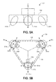
- FIG. 5A is a front schematic view of an exemplary base for a mobile human interface robot.
- FIG. 5B is a top schematic view of an exemplary base for a mobile human interface robot.
- FIG. 5C is a front view of an exemplary holonomic wheel for a mobile human interface robot.
- FIG. 5D is a side view of the wheel shown in FIG. 5C .
- FIG. 6A is a front perspective view of an exemplary torso for a mobile human interface robot.
- FIG. 6B is a front perspective view of an exemplary torso having touch sensing capabilities for a mobile human interface robot.
- FIG. 6C is a bottom perspective view of the torso shown in FIG. 6B .
- FIG. 7 is a front perspective view of an exemplary neck for a mobile human interface robot.
- FIGS. 8A-8G are schematic views of exemplary circuitry for a mobile human interface robot.
- FIG. 9 is a perspective view of an exemplary mobile human interface robot having detachable web pads.
- FIGS. 10A-10E perspective views of people interacting with an exemplary mobile human interface robot.
- FIG. 11 is a schematic view of an exemplary mobile human interface robot.
- FIG. 12 is a perspective view of an exemplary mobile human interface robot having multiple sensors pointed toward the ground.
- FIG. 13 is a schematic view of an exemplary control system executed by a controller of a mobile human interface robot.
- FIG. 14 is a perspective view of an exemplary mobile human interface robot receiving a human touch command.
- FIG. 15 provides an exemplary telephony schematic for initiating and conducting communication with a mobile human interface robot.
- FIGS. 16A-16C provide schematic views of exemplary controller systems for a mobile human interface robot.
- FIG. 16D provides an exemplary arrangement of operations for operating a mobile robot.
- FIG. 17A is a schematic view of an exemplary occupancy map.
- FIG. 17B is a schematic view of a mobile robot having a field of view of a scene in a working area.
- FIG. 18A is a schematic view of an exemplary layout map.
- FIG. 18B is a schematic view of an exemplary robot map corresponding to the layout map shown in FIG. 18A .
- FIG. 18C provide an exemplary arrangement of operations for operating a mobile robot to navigate about an environment using a layout map and a robot map.
- FIG. 19A is a schematic view of an exemplary layout map with triangulation of type layout points.
- FIG. 19B is a schematic view of an exemplary robot map corresponding to the layout map shown in FIG. 19A .
- FIG. 19C provide an exemplary arrangement of operations for determining a target robot map location using a layout map and a robot map.
- FIG. 20A is a schematic view of an exemplary layout map with a centroid of tight layout points.
- FIG. 20B is a schematic view of an exemplary robot map corresponding to the layout map shown in FIG. 20A .
- FIG. 20C provide an exemplary arrangement of operations for determining a target robot map location using a layout map and a robot map.
- FIG. 21A provides an exemplary schematic view of the local perceptual space of a mobile human interface robot while stationary.
- FIG. 21B provides an exemplary schematic view of the local perceptual space of a mobile human interface robot while moving.
- FIG. 21C provides an exemplary schematic view of the local perceptual space of a mobile human interface robot while stationary.
- FIG. 21D provides an exemplary schematic view of the local perceptual space of a mobile human interface robot while moving.
- FIG. 21E provides an exemplary schematic view of a mobile human interface robot with the corresponding sensory field of view moving closely around a corner.
- FIG. 21F provides an exemplary schematic view of a mobile human interface robot with the corresponding sensory field of view moving widely around a corner.
- FIG. 22 provides an exemplary arrangement of operations for operating a mobile robot.
- Mobile robots can interact or interface with humans to provide a number of services that range from home assistance to commercial assistance and more.
- a mobile robot can assist elderly people with everyday tasks, including, but not limited to, maintaining a medication regime, mobility assistance, communication assistance (e.g., video conferencing, telecommunications, Internet access, etc.), home or site monitoring (inside and/or outside), person monitoring, and/or providing a personal emergency response system (PERS).
- the mobile robot can provide videoconferencing (e.g., in a hospital setting), a point of sale terminal, interactive information/marketing terminal, etc.
- a mobile robot 100 includes a robot body 110 (or chassis) that defines a forward drive direction F.
- the robot 100 also includes a drive system 200 , an interfacing module 300 , and a sensor system 400 , each supported by the robot body 110 and in communication with a controller 500 that coordinates operation and movement of the robot 100 .
- a power source 105 e.g., battery or batteries
- the controller 500 may include a computer capable of >1000 MIPS (million instructions per second) and the power source 1058 provides a battery sufficient to power the computer for more than three hours.
- the robot body 110 in the examples shown, includes a base 120 , at least one leg 130 extending upwardly from the base 120 , and a torso 140 supported by the at least one leg 130 .
- the base 120 may support at least portions of the drive system 200 .
- the robot body 110 also includes a neck 150 supported by the torso 140 .
- the neck 150 supports a head 160 , which supports at least a portion of the interfacing module 300 .
- the base 120 includes enough weight (e.g., by supporting the power source 105 (batteries) to maintain a low center of gravity CG B of the base 120 and a low overall center of gravity CG R of the robot 100 for maintaining mechanical stability.
- the base 120 defines a trilaterally symmetric shape (e.g., a triangular shape from the top view).
- the base 120 may include a base chassis 122 that supports a base body 124 having first, second, and third base body portions 124 a , 124 b , 124 c corresponding to each leg of the trilaterally shaped base 120 (see e.g., FIG. 4A ).
- Each base body portion 124 a , 124 b , 124 c can be movably supported by the base chassis 122 so as to move independently with respect to the base chassis 122 in response to contact with an object.
- Each base body portion 124 a , 124 b , 124 c can have an associated contact sensor e.g., capacitive sensor, read switch, etc.) that detects movement of the corresponding base body portion 124 a , 124 b , 124 c with respect to the base chassis 122 .
- an associated contact sensor e.g., capacitive sensor, read switch, etc.
- the drive system 200 provides omni-directional and/or holonomic motion control of the robot 100 .
- omni-directional refers to the ability to move in substantially any planar direction, i.e., side-to-side (lateral), forward/back, and rotational. These directions are generally referred to herein as x, y, and ⁇ z, respectively.
- holonomic is used in a manner substantially consistent with the literature use of the term and refers to the ability to move in a planar direction with three planar degrees of freedom, i.e., two translations and one rotation.
- a holonomic robot has the ability to move in a planar direction at a velocity made up of substantially any proportion of the three planar velocities (forward/back, lateral, and rotational), as well as the ability to change these proportions in a substantially continuous manner.
- the robot 100 can operate in human environments (e.g., environments typically designed for bipedal, walking occupants) using wheeled mobility.
- the drive system 200 includes first, second, and third drive wheels 210 a , 210 b , 210 c equally spaced (i.e., trilaterally symmetric) about the vertical axis Z (e.g., 120 degrees apart); however, other arrangements are possible as well. Referring to FIGS.
- the drive wheels 210 a , 210 b , 210 c may define a transverse arcuate rolling surface (i.e., a curved profile in a direction transverse or perpendicular to the rolling direction D R ), which may aid maneuverability of the holonomic drive system 200 .
- Each drive wheel 210 a , 210 b , 210 c is coupled to a respective drive motor 220 a , 220 b , 220 c that can drive the drive wheel 210 a , 210 b , 210 c in forward and/or reverse directions independently of the other drive motors 220 a , 220 b , 220 c .
- Each drive motor 220 a - c can have a respective encoder 212 ( FIG. 8C ), which provides wheel rotation feedback to the controller 500 .
- each drive wheels 210 a , 210 b , 210 c is mounted on or near one of the three points of an equilateral triangle and having a drive direction (forward and reverse directions) that is perpendicular to an angle bisector of the respective triangle end.
- Driving the trilaterally symmetric holonomic base 120 with a forward driving direction F allows the robot 100 to transition into non forward drive directions for autonomous escape from confinement or clutter and then rotating and/or translating to drive along the forward drive direction F after the escape has been resolved.
- each drive wheel 210 includes inboard and outboard rows 232 , 234 of rollers 230 , each have a rolling direction D r perpendicular to the rolling direction D R of the drive wheel 210 .
- the rows 232 , 234 of rollers 230 can be staggered (e.g., such that one roller 230 of the inboard row 232 is positioned equally between two adjacent rollers 230 of the outboard row 234 .
- the rollers 230 provide infinite slip perpendicular to the drive direction the drive wheel 210 .
- the rollers 230 define an arcuate (e.g., convex) outer surface 235 perpendicular to their rolling directions D r , such that together the rollers 230 define the circular or substantially circular perimeter of the drive wheel 210 .
- the profile of the rollers 230 affects the overall profile of the drive wheel 210 .
- the rollers 230 may define arcuate outer roller surfaces 235 that together define a scalloped rolling surface of the drive wheel 210 (e.g., as treads for traction).
- configuring the rollers 230 to have contours that define a circular overall rolling surface of the drive wheel 210 allows the robot 100 to travel smoothly on a flat surface instead of vibrating vertically with a wheel tread.
- the staggered rows 232 , 234 of rollers 230 can be used as treads to climb objects as tall or almost as tall as a wheel radius R of the drive wheel 210 .
- the first drive wheel 210 a is arranged as a leading drive wheel along the forward drive direction F with the remaining two drive wheels 210 b , 210 c trailing behind.
- the controller 500 may issue a drive command that causes the second and third drive wheels 210 b , 210 c to drive in a forward rolling direction at an equal rate while the first drive wheel 210 a slips along the forward drive direction F.
- this drive wheel arrangement allows the robot 100 to stop short (e.g., incur a rapid negative acceleration against the forward drive direction F). This is due to the natural dynamic instability of the three wheeled design.
- the controller 500 may take into account a moment of inertia I of the robot 100 from its overall center of gravity CG R .
- each drive wheel 210 a , 210 b , 210 has a rolling direction D R radially aligned with a vertical axis Z, which is orthogonal to X and Y axes of the robot 100 .
- the first drive wheel 210 a can be arranged as a leading drive wheel along the forward drive direction F with the remaining two drive wheels 210 b , 210 c trailing behind.
- the controller 500 may issue a drive command that causes the first drive wheel 210 a to drive in a forward rolling direction and the second and third drive wheels 210 b , 210 c to drive at an equal rate as the first drive wheel 210 a , but in a reverse direction.
- the drive system 200 can be arranged to have the first and second drive wheels 210 a , 210 b positioned such that an angle bisector of an angle between the two drive wheels 210 a , 210 b is aligned with the forward drive direction F of the robot 100 .
- the controller 500 may issue a drive command that causes the first and second drive wheels 210 a , 210 b to drive in a forward rolling direction and an equal rate, while the third drive wheel 210 c drives in a reverse direction or remains idle and is dragged behind the first and second drive wheels 210 a , 210 b .
- the controller 500 may issue a command that causes the corresponding first or second drive wheel 210 a , 210 b to drive at relatively quicker/slower rate.
- Other drive system 200 arrangements can be used as well.
- the drive wheels 210 a , 210 b , 210 c may define a cylindrical, circular, elliptical, or polygonal profile.
- the base 120 supports at least one leg 130 extending upward in the Z direction from the base 120 .
- the leg(s) 130 may be configured to have a variable height for raising and lowering the torso 140 with respect to the base 120 .
- each leg 130 includes first and second leg portions 132 , 134 that move with respect to each other (e.g., telescopic, linear, and/or angular movement).
- the leg 130 may include an actuator assembly 136 ( FIG. 8C ) for moving the second leg portion 134 with respect to the first leg portion 132 .
- the actuator assembly 136 may include a motor driver 138 a in communication with a lift motor 138 b and an encoder 138 c , which provides position feedback to the controller 500 .
- telescopic arrangements include successively smaller diameter extrusions telescopically moving up and out of relatively larger extrusions at the base 120 in order to keep a center of gravity CG L of the entire leg 130 as low as possible.
- stronger and/or larger components can be placed at the bottom to deal with the greater torques that will be experienced at the base 120 when the leg 130 is fully extended.
- This approach offers two problems. First, when the relatively smaller components are placed at the top of the leg 130 , any rain, dust, or other particulate will tend to run or fall down the extrusions, infiltrating a space between the extrusions, thus obstructing nesting of the extrusions.
- the second leg portion 134 By having the second leg portion 134 move telescopically over the first leg portion 132 , the second leg portion 134 provides additional payload attachment points that can move vertically with respect to the base 120 .
- This type of arrangement causes water or airborne particulate to run down the torso 140 on the outside of every leg portion 132 , 134 (e.g., extrusion) without entering a space between the leg portions 132 , 134 .
- payload/accessory mounting features of the torso 140 and/or second leg portion 134 are always exposed and available no matter how the leg 130 is extended.
- the leg(s) 130 support the torso 140 , which may have a shoulder 142 extending over and above the base 120 .
- the torso 140 has a downward facing or bottom surface 144 (e.g., toward the base) forming at least part of the shoulder 142 and an opposite upward facing or top surface 146 , with a side surface 148 extending therebetween.
- the torso 140 may define various shapes or geometries, such as a circular or an elliptical shape having a central portion 141 supported by the leg(s) 130 and a peripheral free portion 143 that extends laterally beyond a lateral extent of the leg(s) 130 , thus providing an overhanging portion that defines the downward facing surface 144 .
- the torso 140 defines a polygonal or other complex shape that defines a shoulder, which provides an overhanging portion that extends beyond the leg(s) 130 over the base 120 .
- the robot 100 may include one or more accessory ports 170 (e.g., mechanical and/or electrical interconnect points) for receiving payloads.
- the accessory ports 170 can be located so that received payloads do not occlude or obstruct sensors of the sensor system 400 (e.g., on the bottom and/or top surfaces 144 , 146 of the torso 140 , etc.).
- the torso 140 includes one or more accessory ports 170 on a rearward portion 149 of the torso 140 for receiving a payload in the basket 340 , for example, and so as not to obstruct sensors on a forward portion 147 of the torso 140 or other portions of the robot body 110 .
- An external surface of the torso 140 may be sensitive to contact or touching by a user, so as to receive touch commands from the user. For example, when the user touches the top surface 146 of the torso 140 , the robot 100 responds by lowering a height H T of the torso with respect to the floor (e.g., by decreasing the height H L of the leg(s) 130 supporting the torso 140 ). Similarly, when the user touches the bottom surface 144 of the torso 140 , the robot 100 responds by raising the torso 140 with respect to the floor (e.g., by increasing the height H L of the leg(s) 130 supporting the torso 140 ).
- the robot 100 upon receiving a user touch on forward, rearward, right or left portions of side surface 148 of the torso 140 , the robot 100 responds by moving in a corresponding direction of the received touch command (e.g., rearward, forward, left, and right, respectively).
- the external surface(s) of the torso 140 may include a capacitive sensor in communication with the controller 500 that detects user contact.
- the torso 140 includes a torso body 145 having a top panel 145 t , a bottom panel 145 b , a front panel 145 f , a back panel 145 b , a right panel 145 r and a left panel 145 l .
- Each panel 145 t , 145 b , 145 f , 145 r , 145 r , 145 l may move independently with respect to the other panels.
- each panel 145 t , 145 b , 145 f , 145 r , 145 r , 145 l may have an associated motion and/or contact sensor 147 t , 147 b , 147 f , 147 r , 147 r , 147 l in communication with the controller 500 that detects motion and/or contact with respective panel.
- the torso 140 supports the neck 150 , which provides panning and tilting of the head 160 with respect to the torso 140 .
- the neck 150 includes a rotator 152 and a tilter 154 .
- the rotator 152 may provide a range of angular movement ⁇ R (e.g., about the Z axis) of between about 90° and about 360°. Other ranges are possible as well.
- the rotator 152 includes electrical connectors or contacts that allow continuous 360° rotation of the head 150 with respect to the torso 140 in an unlimited number of rotations while maintaining electrical communication between the head 150 and the remainder of the robot 100 .
- the tilter 154 may include the same or similar electrical connectors or contacts allow rotation of the head 150 with respect to the torso 140 while maintaining electrical communication between the head 150 and the remainder of the robot 100 .
- the rotator 152 may include a rotator motor 151 coupled to or engaging a ring 153 (e.g., a toothed ring rack).
- the tilter 154 may move the head at an angle ⁇ T (e.g., about the Y axis) with respect to the torso 140 independently of the rotator 152 .
- tilter 154 includes a tilter motor 155 , which moves the head 150 between an angle ⁇ T of ⁇ 90° with respect to Z-axis.
- the robot 100 may be configured so that the leg(s) 130 , the torso 140 , the neck 150 , and the head 160 stay within a perimeter of the base 120 for maintaining stable mobility of the robot 100 .
- the neck 150 includes a pan-tilt assembly 151 that includes the rotator 152 and a tilter 154 along with corresponding motor drivers 156 a , 156 b and encoders 158 a , 158 b.
- the head 160 may be sensitive to contact or touching by a user, so as to receive touch commands from the user. For example, when the user pulls the head 160 forward, the head 160 tilts forward with passive resistance and then holds the position. More over, if the user pushes/pulls the head 160 vertically downward, the torso 140 may lower (via a reduction in length of the leg 130 ) to lower the head 160 .
- the head 160 and/or neck 150 may include strain gauges and/or contact sensors 165 ( FIG. 7 ) that sense user contact or manipulation.
- FIGS. 8A-8G provide exemplary schematics of circuitry for the robot 100 .
- FIGS. 8A-8C provide exemplary schematics of circuitry for the base 120 , which may house the proximity sensors, such as the sonar proximity sensors 410 and the cliff proximity sensors 420 , contact sensors 430 , the laser scanner 440 , the sonar scanner 460 , and the drive system 200 .
- the base 120 may also house the controller 500 , the power source 105 , and the leg actuator assembly 136 .
- the torso 140 may house a microcontroller 145 , the microphone(s) 330 , the speaker(s) 340 , the scanning 3-D image sensor 450 a , and a torso touch sensor system 480 , which allows the controller 500 to receive and respond to user contact or touches (e.g., as by moving the torso 140 with respect to the base 120 , panning and/or tilting the neck 150 , and/or issuing commands to the drive system 200 in response thereto).
- a microcontroller 145 the microphone(s) 330 , the speaker(s) 340 , the scanning 3-D image sensor 450 a , and a torso touch sensor system 480 , which allows the controller 500 to receive and respond to user contact or touches (e.g., as by moving the torso 140 with respect to the base 120 , panning and/or tilting the neck 150 , and/or issuing commands to the drive system 200 in response thereto).
- the neck 150 may house a pan-tilt assembly 151 that may include a pan motor 152 having a corresponding motor driver 156 a and encoder 138 a , and a tilt motor 154 152 having a corresponding motor driver 156 b and encoder 138 b .
- the head 160 may house one or more web pads 310 and a camera 320 .
- the head 160 supports one or more portions of the interfacing module 300 .
- the head 160 may include a dock 302 for releasably receiving one or more computing tablets 310 , also referred to as a web pad or a tablet PC, each of which may have a touch screen 312 .
- the web pad 310 may be oriented forward, rearward or upward.
- web pad 310 includes a touch screen, optional I/O (e.g., buttons and/or connectors, such as micro-USB, etc.) a processor, and memory in communication with the processor.
- An exemplary web pad 310 includes the Apple iPad is by Apple, Inc.
- the web pad and 10 functions as the controller 500 or assist the controller 500 and controlling the robot 100 .
- the dock 302 includes a first computing tablet 310 a fixedly attached thereto (e.g., a wired interface for data transfer at a relatively higher bandwidth, such as a gigabit rate) and a second computing tablet 310 b removably connected thereto.
- the second web pad 310 b may be received over the first web pad 310 a as shown in FIG. 9 , or the second web pad 310 b may be received on an opposite facing side or other side of the head 160 with respect to the first web pad 310 a .
- the head 160 supports a single web pad 310 , which may be either fixed or removably attached thereto.
- the touch screen 312 may detected, monitor, and/or reproduce points of user touching thereon for receiving user inputs and providing a graphical user interface that is touch interactive.
- the web pad 310 includes a touch screen caller that allows the user to find it when it has been removed from the robot 100 .
- the robot 100 includes multiple web pad docks 302 on one or more portions of the robot body 110 .
- the robot 100 includes a web pad dock 302 optionally disposed on the leg 130 and/or the torso 140 . This allows the user to dock a web pad 310 at different heights on the robot 100 , for example, to accommodate users of different height, capture video using a camera of the web pad 310 in different vantage points, and/or to receive multiple web pads 310 on the robot 100 .
- the interfacing module 300 may include a camera 320 disposed on the head 160 (see e.g., FIGS. 2 ), which can be used to capture video from elevated vantage point of the head 160 (e.g., for videoconferencing).
- the camera 320 is disposed on the neck 150 .
- the camera 320 is operated only when the web pad 310 , 310 a is detached or undocked from the head 160 .
- the robot 100 may use a camera of the web pad 310 a for capturing video.
- the camera 320 may be disposed behind the docked web pad 310 and enters an active state when the web pad 310 is detached or undocked from the head 160 and an inactive state when the web pad 310 is attached or docked on the head 160 .
- the robot 100 can provide videoconferencing (e.g., at 24 fps) through the interface module 300 (e.g., using a web pad 310 , the camera 320 , the microphones 320 , and/or the speakers 340 ).
- the videoconferencing can be multiparty.
- the robot 100 can provide eye contact between both parties of the videoconferencing by maneuvering the head 160 to face the user.
- the robot 100 can have a gaze angle of ⁇ 5 degrees (e.g., an angle away from an axis normal to the forward face of the head 160 ).
- At least one 3-D image sensor 450 and/or the camera 320 on the robot 100 can capture life size images including body language.
- the controller 500 can synchronize audio and video (e.g., with the difference of ⁇ 50 ms).
- robot 100 can provide videoconferencing for people standing or sitting by adjusting the height of the web pad 310 on the head 160 and/or the camera 320 (by raising or lowering the torso 140 ) and/or panning and/or tilting the head 160 .
- the camera 320 may be movable within at least one degree of freedom separately from the web pad 310 .
- the camera 320 has an objective lens positioned more than 3 feet from the ground, but no more than 10 percent of the web pad height from a top edge of a display area of the web pad 310 .
- the robot 100 can zoom the camera 320 to obtain close-up pictures or video about the robot 100 .
- the head 160 may include one or more speakers 340 so as to have sound emanate from the head 160 near the web pad 310 displaying the videoconferencing.
- the robot 100 can receive user inputs into the web pad 310 (e.g., via a touch screen), as shown in FIG. 10E .
- the web pad 310 is a display or monitor, while in other implementations the web pad 310 is a tablet computer.
- the web pad 310 can have easy and intuitive controls, such as a touch screen, providing high interactivity.
- the web pad 310 may have a monitor display 312 (e.g., touch screen) having a display area of 150 square inches or greater movable with at least one degree of freedom.
- the robot 100 can provide EMR integration, in some examples, by providing video conferencing between a doctor and patient and/or other doctors or nurses.
- the robot 100 may include pass-through consultation instruments.
- the robot 100 may include a stethoscope configured to pass listening to the videoconferencing user (e.g., a doctor).
- the robot includes connectors 170 that allow direct connection to Class II medical devices, such as electronic stethoscopes, otoscopes and ultrasound, to transmit medical data to a remote user (physician).
- a user may remove the web pad 310 from the web pad dock 302 on the head 160 for remote operation of the robot 100 , videoconferencing (e.g., using a camera and microphone of the web pad 310 ), and/or usage of software applications on the web pad 310 .
- the robot 100 may include first and second cameras 320 a , 320 b on the head 160 to obtain different vantage points for videoconferencing, navigation, etc., while the web pad 310 is detached from the web pad dock 302 .
- Interactive applications executable on the controller 500 and/or in communication with the controller 500 may require more than one display on the robot 100 .
- Multiple web pads 310 associated with the robot 100 can provide different combinations of “FaceTime”, Telestration, HD look at this-cam (e.g., for web pads 310 having built in cameras), can act as a remote operator control unit (OCU) for controlling the robot 100 remotely, and/or provide a local user interface pad.
- OCU remote operator control unit
- the interfacing module 300 may include a microphone 330 (e.g., or micro-phone array) for receiving sound inputs and one or more speakers 330 disposed on the robot body 110 for delivering sound outputs.
- the microphone 330 and the speaker(s) 340 may each communicate with the controller 500 .
- the interfacing module 300 includes a basket 360 , which may be configured to hold brochures, emergency information, household items, and other items.
- the sensor system 400 may include several different types of sensors which can be used in conjunction with one another to create a perception of the robot's environment sufficient to allow the robot 100 to make intelligent decisions about actions to take in that environment.
- the sensor system 400 may include one or more types of sensors supported by the robot body 110 , which may include obstacle detection obstacle avoidance (ODOA) sensors, communication sensors, navigation sensors, etc.
- ODOA obstacle detection obstacle avoidance
- these sensors may include, but not limited to, proximity sensors, contact sensors, three-dimensional (3D) imaging/depth map sensors, a camera (e.g., visible light and/or infrared camera), sonar, radar, LIDAR (Light Detection And Ranging, which can entail optical remote sensing that measures properties of scattered light to find range and/or other information of a distant target), LADAR (Laser Detection and Ranging), etc.
- a camera e.g., visible light and/or infrared camera
- sonar e.g., sonar
- radar e.g., radar
- LIDAR Light Detection And Ranging
- LADAR Laser Detection and Ranging
- the sensor system 400 includes ranging sonar sensors 410 (e.g., nine about a perimeter of the base 120 ), proximity cliff detectors 420 , contact sensors 430 , a laser scanner 440 , one or more 3-D imaging/depth sensors 450 , and an imaging sonar 460 .
- the sensors need to be placed such that they have maximum coverage of areas of interest around the robot 100 .
- the sensors may need to be placed in such a way that the robot 100 itself causes an absolute minimum of occlusion to the sensors; in essence, the sensors cannot be placed such that they are “blinded” by the robot itself.
- the placement and mounting of the sensors should not be intrusive to the rest of the industrial design of the platform. In terms of aesthetics, it can be assumed that a robot with sensors mounted inconspicuously is more “attractive” than otherwise. In terms of utility, sensors should be mounted in a manner so as not to interfere with normal robot operation (snagging on obstacles, etc.).
- the sensor system 400 includes a set or an array of proximity sensors 410 , 420 in communication with the controller 500 and arranged in one or more zones or portions of the robot 100 (e.g., disposed on or near the base body portion 124 a , 124 b , 124 c of the robot body 110 ) for detecting any nearby or intruding obstacles.
- the proximity sensors 410 , 420 may be converging infrared (IR) emitter-sensor elements, sonar sensors, ultrasonic sensors, and/or imaging sensors (e.g., 3D depth map image sensors) that provide a signal to the controller 500 when an object is within a given range of the robot 100 .
- IR infrared
- the robot 100 includes an array of sonar-type proximity sensors 410 disposed (e.g., substantially equidistant) around the base body 120 and arranged with an upward field of view.
- First, second, and third sonar proximity sensors 410 a , 410 b , 410 c are disposed on or near the first (forward) base body portion 124 a , with at least one of the sonar proximity sensors near a radially outer-most edge 125 a of the first base body 124 a .
- fourth, fifth, and sixth sonar proximity sensors 410 d , 410 e , 410 f are disposed on or near the second (right) base body portion 124 b , with at least one of the sonar proximity sensors near a radially outer-most edge 125 b of the second base body 124 b .
- Seventh, eighth, and ninth sonar proximity sensors 410 g , 410 h , 410 i are disposed on or near the third (right) base body portion 124 c , with at least one of the sonar proximity sensors near a radially outer-most edge 125 c of the third base body 124 c .
- This configuration provides at least three zones of detection.
- the set of sonar proximity sensors 410 (e.g., 410 a - 410 i ) disposed around the base body 120 are arranged to point upward (e.g., substantially in the Z direction) and optionally angled outward away from the Z axis, thus creating a detection curtain 412 around the robot 100 .
- Each sonar proximity sensor 410 a - 410 i may have a shroud or emission guide 414 that guides the sonar emission upward or at least not toward the other portions of the robot body 110 (e.g., so as not to detect movement of the robot body 110 with respect to itself).
- the emission guide 414 may define a shell or half shell shape.
- the base body 120 extends laterally beyond the leg 130 , and the sonar proximity sensors 410 (e.g., 410 a - 410 i ) are disposed on the base body 120 (e.g., substantially along a perimeter of the base body 120 ) around the leg 130 . Moreover, the upward pointing sonar proximity sensors 410 are spaced to create a continuous or substantially continuous sonar detection curtain 412 around the leg 130 .
- the sonar detection curtain 412 can be used to detect obstacles having elevated lateral protruding portions, such as table tops, shelves, etc.
- the upward looking sonar proximity sensors 410 provide the ability to see objects that are primarily in the horizontal plane, such as table tops. These objects, due to their aspect ratio, may be missed by other sensors of the sensor system, such as the laser scanner 440 or imaging sensors 450 , and as such, can pose a problem to the robot 100 .
- the upward viewing sonar proximity sensors 410 arranged around the perimeter of the base 120 provide a means for seeing or detecting those type of objects/obstacles.
- the sonar proximity sensors 410 can be placed around the widest points of the base perimeter and angled slightly outwards, so as not to be occluded or obstructed by the torso 140 or head 160 of the robot 100 , thus not resulting in false positives for sensing portions of the robot 100 itself
- the sonar proximity sensors 410 are arranged (upward and outward) to leave a volume about the torso 140 outside of a field of view of the sonar proximity sensors 410 and thus free to receive mounted payloads or accessories, such as the basket 340 .
- the sonar proximity sensors 410 can be recessed into the base body 124 to provide visual concealment and no external features to snag on or hit obstacles.
- the sensor system 400 may include or more sonar proximity sensors 410 (e.g., a rear proximity sensor 410 j ) directed rearward (e.g., opposite to the forward drive direction F) for detecting obstacles while backing up.
- the rear sonar proximity sensor 410 j may include an emission guide 414 to direct its sonar detection field 412 .
- the rear sonar proximity sensor 410 j can be used for ranging to determine a distance between the robot 100 and a detected object in the field of view of the rear sonar proximity sensor 410 j (e.g., as “back-up alert”).
- the rear sonar proximity sensor 410 j is mounted recessed within the base body 120 so as to not provide any visual or functional irregularity in the housing form.
- the robot 100 includes cliff proximity sensors 420 arranged near or about the drive wheels 210 a , 210 b , 210 c , so as to allow cliff detection before the drive wheels 210 a , 210 b , 210 c encounter a cliff (e.g., stairs).
- a cliff proximity sensors 420 can be located at or near each of the radially outer-most edges 125 a - c of the base bodies 124 a - c and in locations therebetween.
- cliff sensing is implemented using infrared (IR) proximity or actual range sensing, using an infrared emitter 422 and an infrared detector 424 angled toward each other so as to have an overlapping emission and detection fields, and hence a detection zone, at a location where a floor should be expected.
- IR proximity sensing can have a relatively narrow field of view, may depend on surface albedo for reliability, and can have varying range accuracy from surface to surface.
- multiple discrete sensors can be placed about the perimeter of the robot 100 to adequately detect cliffs from multiple points on the robot 100 .
- IR proximity based sensors typically cannot discriminate between a cliff and a safe event, such as just after the robot 100 climbs a threshold.
- the cliff proximity sensors 420 can detect when the robot 100 has encountered a falling edge of the floor, such as when it encounters a set of stairs.
- the controller 500 (executing a control system) may execute behaviors that cause the robot 100 to take an action, such as changing its direction of travel, when an edge is detected.
- the sensor system 400 includes one or more secondary cliff sensors (e.g., other sensors configured for cliff sensing and optionally other types of sensing).
- the cliff detecting proximity sensors 420 can be arranged to provide early detection of cliffs, provide data for discriminating between actual cliffs and safe events (such as climbing over thresholds), and be positioned down and out so that their field of view includes at least part of the robot body 110 and an area away from the robot body 110 .
- the controller 500 executes cliff detection routine that identifies and detects an edge of the supporting work surface (e.g., floor), an increase in distance past the edge of the work surface, and/or an increase in distance between the robot body 110 and the work surface.
- cliff detection routine that identifies and detects an edge of the supporting work surface (e.g., floor), an increase in distance past the edge of the work surface, and/or an increase in distance between the robot body 110 and the work surface.
- This implementation allows: 1) early detection of potential cliffs (which may allow faster mobility speeds in unknown environments); 2) increased reliability of autonomous mobility since the controller 500 receives cliff imaging information from the cliff detecting proximity sensors 420 to know if a cliff event is truly unsafe or if it can be safely traversed (e.g., such as climbing up and over a threshold); 3) a reduction in false positives of cliffs (e.g., due to the use of edge detection versus the multiple discrete IR proximity sensors with a narrow field of view). Additional sensors arranged as “wheel drop” sensors can be used for redundancy and for detecting situations where a range-sensing camera cannot reliably detect a certain type of cliff.
- Threshold and step detection allows the robot 100 to effectively plan for either traversing a climb-able threshold or avoiding a step that is too tall. This can be the same for random objects on the work surface that the robot 100 may or may not be able to safely traverse. For those obstacles or thresholds that the robot 100 determines it can climb, knowing their heights allows the robot 100 to slow down appropriately, if deemed needed, to allow for a smooth transition in order to maximize smoothness and minimize any instability due to sudden accelerations.
- threshold and step detection is based on object height above the work surface along with geometry recognition (e.g., discerning between a threshold or an electrical cable versus a blob, such as a sock). Thresholds may be recognized by edge detection.
- the controller 500 may receive imaging data from the cliff detecting proximity sensors 420 (or another imaging sensor on the robot 100 ), execute an edge detection routine, and issue a drive command based on results of the edge detection routine.
- the controller 500 may use pattern recognition to identify objects as well. Threshold detection allows the robot 100 to change its orientation with respect to the threshold to maximize smooth step climbing ability.
- the proximity sensors 410 , 420 may function alone, or as an alternative, may function in combination with one or more contact sensors 430 (e.g., bump switches) for redundancy.
- one or more contact or bump sensors 430 on the robot body 110 can detect if the robot 100 physically encounters an obstacle.
- Such sensors may use a physical property such as capacitance or physical displacement within the robot 100 to determine when it has encountered an obstacle.
- each base body portion 124 a , 124 b , 124 c of the base 120 has an associated contact sensor 430 (e.g., capacitive sensor, read switch, etc.) that detects movement of the corresponding base body portion 124 a , 124 b , 124 c with respect to the base chassis 122 (see e.g., FIG. 4A ).
- each base body 124 a - c may move radially with respect to the Z axis of the base chassis 122 , so as to provide 3 -way bump detection.
- the sensor system 400 includes a laser scanner 440 mounted on a forward portion of the robot body 110 and in communication with the controller 500 .
- the laser scanner 440 is mounted on the base body 120 facing forward (e.g., having a field of view along the forward drive direction F) on or above the first base body 124 a (e.g., to have maximum imaging coverage along the drive direction F of the robot).
- the placement of the laser scanner on or near the front tip of the triangular base 120 means that the external angle of the robotic base (e.g., 300 degrees) is greater than a field of view 442 of the laser scanner 440 (e.g., ⁇ 285 degrees), thus preventing the base 120 from occluding or obstructing the detection field of view 442 of the laser scanner 440 .
- the laser scanner 440 can be mounted recessed within the base body 124 as much as possible without occluding its fields of view, to minimize any portion of the laser scanner sticking out past the base body 124 (e.g., for aesthetics and to minimize snagging on obstacles).
- the laser scanner 440 scans an area about the robot 100 and the controller 500 , using signals received from the laser scanner 440 , creates an environment map or object map of the scanned area.
- the controller 500 may use the object map for navigation, obstacle detection, and obstacle avoidance.
- the controller 500 may use sensory inputs from other sensors of the sensor system 400 for creating object map and/or for navigation.
- the laser scanner 440 is a scanning LIDAR, which may use a laser that quickly scans an area in one dimension, as a “main” scan line, and a time-of-flight imaging element that uses a phase difference or similar technique to assign a depth to each pixel generated in the line (returning a two dimensional depth line in the plane of scanning)
- the LIDAR can perform an “auxiliary” scan in a second direction (for example, by “nodding” the scanner).
- This mechanical scanning technique can be complemented, if not supplemented, by technologies such as the “Flash” LIDAR/LADAR and “Swiss Ranger” type focal plane imaging element sensors, techniques which use semiconductor stacks to permit time of flight calculations for a full 2-D matrix of pixels to provide a depth at each pixel, or even a series of depths at each pixel (with an encoded illuminator or illuminating laser).
- technologies such as the “Flash” LIDAR/LADAR and “Swiss Ranger” type focal plane imaging element sensors, techniques which use semiconductor stacks to permit time of flight calculations for a full 2-D matrix of pixels to provide a depth at each pixel, or even a series of depths at each pixel (with an encoded illuminator or illuminating laser).
- the sensor system 400 may include one or more three-dimensional (3-D) image sensors 450 in communication with the controller 500 . If the 3-D image sensor 450 has a limited field of view, the controller 500 or the sensor system 400 can actuate the 3-D image sensor 450 a in a side-to-side scanning manner to create a relatively wider field of view to perform robust ODOA.
- the robot 100 includes a scanning 3-D image sensor 450 a mounted on a forward portion of the robot body 110 with a field of view along the forward drive direction F (e.g., to have maximum imaging coverage along the drive direction F of the robot).
- the scanning 3-D image sensor 450 a can be used primarily for obstacle detection/obstacle avoidance (ODOA).
- the scanning 3-D image sensor 450 a is mounted on the torso 140 underneath the shoulder 142 or on the bottom surface 144 and recessed within the torso 140 (e.g., flush or past the bottom surface 144 ), as shown in FIG. 3 , for example, to prevent user contact with the scanning 3-D image sensor 450 a .
- the scanning 3-D image sensor 450 can be arranged to aim substantially downward and away from the robot body 110 , so as to have a downward field of view 452 in front of the robot 100 for obstacle detection and obstacle avoidance (ODOA) (e.g., with obstruction by the base 120 or other portions of the robot body 110 ).
- ODOA obstacle detection and obstacle avoidance
- Placement of the scanning 3-D image sensor 450 a on or near a forward edge of the torso 140 allows the field of view of the 3-D image sensor 450 (e.g., ⁇ 285 degrees) to be less than an external surface angle of the torso 140 (e.g., 300 degrees) with respect to the 3-D image sensor 450 , thus preventing the torso 140 from occluding or obstructing the detection field of view 452 of the scanning 3-D image sensor 450 a .
- the scanning 3-D image sensor 450 a (and associated actuator) can be mounted recessed within the torso 140 as much as possible without occluding its fields of view (e.g., also for aesthetics and to minimize snagging on obstacles).
- the distracting scanning motion of the scanning 3-D image sensor 450 a is not visible to a user, creating a less distracting interaction experience.
- the recessed scanning 3-D image sensor 450 a will not tend to have unintended interactions with the environment (snagging on people, obstacles, etc.), especially when moving or scanning, as virtually no moving part extends beyond the envelope of the torso 140 .
- the sensor system 400 includes additional 3-D image sensors 450 disposed on the base body 120 , the leg 130 , the neck 150 , and/or the head 160 .
- the robot 100 includes 3-D image sensors 450 on the base body 120 , the torso 140 , and the head 160 .
- the robot 100 includes 3-D image sensors 450 on the base body 120 , the torso 140 , and the head 160 .
- the robot 100 includes 3-D image sensors 450 on the leg 130 , the torso 140 , and the neck 150 .
- Other configurations are possible as well.
- One 3-D image sensor 450 (e.g., on the neck 150 and over the head 160 ) can be used for people recognition, gesture recognition, and/or videoconferencing, while another 3-D image sensor 450 (e.g., on the base 120 and/or the leg 130 ) can be used for navigation and/or obstacle detection and obstacle avoidance.
- a forward facing 3-D image sensor 450 disposed on the neck 150 and/or the head 160 can be used for person, face, and/or gesture recognition of people about the robot 100 .
- the controller 500 may recognize a user by creating a three-dimensional map of the viewed/captured user's face and comparing the created three-dimensional map with known 3-D images of people's faces and determining a match with one of the known 3-D facial images. Facial recognition may be used for validating users as allowable users of the robot 100 .
- one or more of the 3-D image sensors 450 can be used for determining gestures of person viewed by the robot 100 , and optionally reacting based on the determined gesture(s) (e.g., hand pointing, waving, and or hand signals). For example, the controller 500 may issue a drive command in response to a recognized hand point in a particular direction.
- the 3-D image sensors 450 may be capable of producing the following types of data: (i) a depth map, (ii) a reflectivity based intensity image, and/or (iii) a regular intensity image.
- the 3-D image sensors 450 may obtain such data by image pattern matching, measuring the flight time and/or phase delay shift for light emitted from a source and reflected off of a target.
- reasoning or control software executable on a processor (e.g., of the robot controller 500 ), uses a combination of algorithms executed using various data types generated by the sensor system 400 .
- the reasoning software processes the data collected from the sensor system 400 and outputs data for making navigational decisions on where the robot 100 can move without colliding with an obstacle, for example.
- the reasoning software can in turn apply effective methods to selected segments of the sensed image(s) to improve depth measurements of the 3-D image sensors 450 . This may include using appropriate temporal and spatial averaging techniques.
- the reliability of executing robot collision free moves may be based on: (i) a confidence level built by high level reasoning over time and (ii) a depth-perceptive sensor that accumulates three major types of data for analysis—(a) a depth image, (b) an active illumination image and (c) an ambient illumination image. Algorithms cognizant of the different types of data can be executed on each of the images obtained by the depth-perceptive imaging sensor 450 . The aggregate data may improve the confidence level a compared to a system using only one of the kinds of data.
- the 3-D image sensors 450 may obtain images containing depth and brightness data from a scene about the robot 100 (e.g., a sensor view portion of a room or work area) that contains one or more objects.
- the controller 500 may be configured to determine occupancy data for the object based on the captured reflected light from the scene.
- the controller 500 issues a drive command to the drive system 200 based at least in part on the occupancy data to circumnavigate obstacles (i.e., the object in the scene).
- the 3-D image sensors 450 may repeatedly capture scene depth images for real-time decision making by the controller 500 to navigate the robot 100 about the scene without colliding into any objects in the scene.
- the speed or frequency in which the depth image data is obtained by the 3-D image sensors 450 may be controlled by a shutter speed of the 3-D image sensors 450 .
- the controller 500 may receive an event trigger (e.g., from another sensor component of the sensor system 400 , such as proximity sensor 410 , 420 , notifying the controller 500 of a nearby object or hazard.
- the controller 500 in response to the event trigger, can cause the 3-D image sensors 450 to increase a frequency at which depth images are captured and occupancy information is obtained.
- the robot includes a sonar scanner 460 for acoustic imaging of an area surrounding the robot 100 .
- the sonar scanner 460 is disposed on a forward portion of the base body 120 .
- the robot 100 uses the laser scanner or laser range finder 440 for redundant sensing, as well as a rear-facing sonar proximity sensor 410 j for safety, both of which are oriented parallel to the ground G.
- the robot 100 may include first and second 3-D image sensors 450 a , 450 b (depth cameras) to provide robust sensing of the environment around the robot 100 .
- the first 3-D image sensor 450 a is mounted on the torso 140 and pointed downward at a fixed angle to the ground G.
- the robot 100 By angling the first 3-D image sensor 450 a downward, the robot 100 receives dense sensor coverage in an area immediately forward or adjacent to the robot 100 , which is relevant for short-term travel of the robot 100 in the forward direction.
- the rear-facing sonar 410 j provides object detection when the robot travels backward. If backward travel is typical for the robot 100 , the robot 100 may include a third 3D image sensor 450 facing downward and backward to provide dense sensor coverage in an area immediately rearward or adjacent to the robot 100 .
- the second 3-D image sensor 450 b is mounted on the head 160 , which can pan and tilt via the neck 150 .
- the second 3-D image sensor 450 b can be useful for remote driving since it allows a human operator to see where the robot 100 is going.
- the neck 150 enables the operator tilt and/or pan the second 3-D image sensor 450 b to see both close and distant objects. Panning the second 3-D image sensor 450 b increases an associated horizontal field of view.
- the robot 100 may tilt the second 3-D image sensor 450 b downward slightly to increase a total or combined field of view of both 3-D image sensors 450 a , 450 b , and to give sufficient time for the robot 100 to avoid an obstacle (since higher speeds generally mean less time to react to obstacles).
- the robot 100 may tilt the second 3-D image sensor 450 b upward or substantially parallel to the ground G to track a person that the robot 100 is meant to follow. Moreover, while driving at relatively low speeds, the robot 100 can pan the second 3-D image sensor 450 b to increase its field of view around the robot 100 .
- the first 3-D image sensor 450 a can stay fixed (e.g., not moved with respect to the base 120 ) when the robot is driving to expand the robot's perceptual range.
- At least one of 3-D image sensors 450 can be a volumetric point cloud imaging device (such as a speckle or time-of-flight camera) positioned on the robot 100 at a height of greater than 1 or 2 feet above the ground (or at a height of about 1 or 2 feet above the ground) and directed to be capable of obtaining a point cloud from a volume of space including a floor plane in a direction of movement of the robot (via the omni-directional drive system 200 ).
- a volumetric point cloud imaging device such as a speckle or time-of-flight camera
- the first 3-D image sensor 450 a can be positioned on the base 120 at height of greater than 1 or 2 feet above the ground and aimed along the forward drive direction F to capture images (e.g., volumetric point cloud) of a volume including the floor while driving (e.g., for obstacle detection and obstacle avoidance).
- the second 3-D image sensor 450 b is shown mounted on the head 160 (e.g., at a height greater than about 3 or 4 feet above the ground), so as to be capable of obtaining skeletal recognition and definition point clouds from a volume of space adjacent the robot 100 .
- the controller 500 may execute skeletal/digital recognition software to analyze data of the captured volumetric point clouds.
- the sensor system 400 may include an inertial measurement unit (IMU) 470 in communication with the controller 500 to measure and monitor a moment of inertia of the robot 100 with respect to the overall center of gravity CG R of the robot 100 .
- IMU inertial measurement unit
- the controller 500 may monitor any deviation in feedback from the IMU 470 from a threshold signal corresponding to normal unencumbered operation. For example, if the robot begins to pitch away from an upright position, it may be “clothes lined” or otherwise impeded, or someone may have suddenly added a heavy payload. In these instances, it may be necessary to take urgent action (including, but not limited to, evasive maneuvers, recalibration, and/or issuing an audio/visual warning) in order to assure safe operation of the robot 100 .
- urgent action including, but not limited to, evasive maneuvers, recalibration, and/or issuing an audio/visual warning
- robot 100 may operate in a human environment, it may interact with humans and operate in spaces designed for humans (and without regard for robot constraints).
- the robot 100 can limit its drive speeds and accelerations when in a congested, constrained, or highly dynamic environment, such as at a cocktail party or busy hospital.
- the robot 100 may encounter situations where it is safe to drive relatively fast, as in a long empty corridor, but yet be able to decelerate suddenly, as when something crosses the robots' motion path.
- the controller 500 may take into account a moment of inertia of the robot 100 from its overall center of gravity CG R to prevent robot tipping.
- the controller 500 may use a model of its pose, including its current moment of inertia.
- the controller 500 may measure a load impact on the overall center of gravity CG R and monitor movement of the robot moment of inertia.
- the torso 140 and/or neck 150 may include strain gauges to measure strain.
- the controller 500 may apply a test torque command to the drive wheels 210 and measure actual linear and angular acceleration of the robot using the IMU 470 , in order to experimentally determine safe limits.
- a commanded load on the second and third drive wheels 210 b , 210 c (the rear wheels) is reduced, while the first drive wheel 210 a (the front wheel) slips in the forward drive direction and supports the robot 100 .
- the robot 100 may “yaw” which will reduce dynamic stability.
- the IMU 470 e.g., a gyro
- the robot 100 includes multiple antennas.
- the robot 100 includes a first antenna 490 a and a second antenna 490 b both disposed on the base 120 (although the antennas may be disposed at any other part of the robot 100 , such as the leg 130 , the torso 140 , the neck 150 , and/or the head 160 ).
- the use of multiple antennas provide robust signal reception and transmission.
- the use of multiple antennas provides the robot 100 with multiple-input and multiple-output, or MIMO, which is the use of multiple antennas for a transmitter and/or a receiver to improve communication performance. MIMO offers significant increases in data throughput and link range without additional bandwidth or transmit power.
- MIMO is an important part of modern wireless communication standards such as IEEE 802.11n (Wifi), 4G, 3GPP Long Term Evolution, WiMAX and HSPA+.
- the robot 100 can act as a Wi-Fi bridge, hub or hotspot for other electronic devices nearby.
- the mobility and use of MIMO of the robot 100 can allow the robot to come a relatively very reliable Wi-Fi bridge.
- Pre-coding is a type of multi-stream beam forming and is considered to be all spatial processing that occurs at the transmitter.
- the same signal is emitted from each of the transmit antennas with appropriate phase (and sometimes gain) weighting such that the signal power is maximized at the receiver input.
- the benefits of beam forming are to increase the received signal gain, by making signals emitted from different antennas add up constructively, and to reduce the multipath fading effect. In the absence of scattering, beam forming can result in a well defined directional pattern.
- the transmit beam forming cannot simultaneously maximize the signal level at all of the receive antennas, and pre-coding with multiple streams can be used.
- Pre-coding may require knowledge of channel state information (CSI) at the transmitter.
- CSI channel state information
- Spatial multiplexing requires a MIMO antenna configuration.
- a high rate signal is split into multiple lower rate streams and each stream is transmitted from a different transmit antenna in the same frequency channel. If these signals arrive at the receiver antenna array with sufficiently different spatial signatures, the receiver can separate these streams into (almost) parallel channels.
- Spatial multiplexing is a very powerful technique for increasing channel capacity at higher signal-to-noise ratios (SNR). The maximum number of spatial streams is limited by the lesser in the number of antennas at the transmitter or receiver.
- Spatial multiplexing can be used with or without transmit channel knowledge. Spatial multiplexing can also be used for simultaneous transmission to multiple receivers, known as space-division multiple access. By scheduling receivers with different spatial signatures, good separability can be assured.
- Diversity Coding techniques can be used when there is no channel knowledge at the transmitter.
- a single stream (unlike multiple streams in spatial multiplexing) is transmitted, but the signal is coded using techniques called space-time coding.
- the signal is emitted from each of the transmit antennas with full or near orthogonal coding.
- Diversity coding exploits the independent fading in the multiple antenna links to enhance signal diversity. Because there is no channel knowledge, there is no beam forming or array gain from diversity coding.
- Spatial multiplexing can also be combined with pre-coding when the channel is known at the transmitter or combined with diversity coding when decoding reliability is in trade-off.
- the robot 100 includes a third antenna 490 c and/or a fourth antenna 490 d and the torso 140 and/or the head 160 , respectively (see e.g., FIG. 3 ).
- the controller 500 can determine an antenna arrangement (e.g., by moving the antennas 490 a - d , as by raising or lowering the torso 140 and/or rotating and/or tilting the head 160 ) that achieves a threshold signal level for robust communication.
- the controller 500 can issue a command to elevate the third and fourth antennas 490 c , 490 d by raising a height of the torso 140 .
- the controller 500 can issue a command to rotate and/or the head 160 to further orient the fourth antenna 490 d with respect to the other antennas 490 a - c.
- the controller 500 executes a control system 510 , which includes a control arbitration system 510 a and a behavior system 510 b in communication with each other.
- the control arbitration system 510 a allows applications 520 to be dynamically added and removed from the control system 510 , and facilitates allowing applications 520 to each control the robot 100 without needing to know about any other applications 520 .
- the control arbitration system 510 a provides a simple prioritized control mechanism between applications 520 and resources 530 of the robot 100 .
- the resources 530 may include the drive system 200 , the sensor system 400 , and/or any payloads or controllable devices in communication with the controller 500 .
- the applications 520 can be stored in memory of or communicated to the robot 100 , to run concurrently on (e.g., a processor) and simultaneously control the robot 100 .
- the applications 520 may access behaviors 600 of the behavior system 510 b .
- the independently deployed applications 520 are combined dynamically at runtime and to share robot resources 530 (e.g., drive system 200 , arm(s), head(s), etc.) of the robot 100 .
- a low-level policy is implemented for dynamically sharing the robot resources 530 among the applications 520 at run-time.
- the policy determines which application 520 has control of the robot resources 530 required by that application 520 (e.g. a priority hierarchy among the applications 520 ).
- Applications 520 can start and stop dynamically and run completely independently of each other.
- the control system 510 also allows for complex behaviors 600 which can be combined together to assist each other.
- the control arbitration system 510 a includes one or more resource controllers 540 , a robot manager 550 , and one or more control arbiters 560 . These components do not need to be in a common process or computer, and do not need to be started in any particular order.
- the resource controller 540 component provides an interface to the control arbitration system 510 a for applications 520 . There is an instance of this component for every application 520 .
- the resource controller 540 abstracts and encapsulates away the complexities of authentication, distributed resource control arbiters, command buffering, and the like.
- the robot manager 550 coordinates the prioritization of applications 520 , by controlling which application 520 has exclusive control of any of the robot resources 530 at any particular time.
- the robot manager 550 implements a priority policy, which has a linear prioritized order of the resource controllers 540 , and keeps track of the resource control arbiters 560 that provide hardware control.
- the control arbiter 560 receives the commands from every application 520 and generates a single command based on the applications' priorities and publishes it for its associated resources 530 .
- the control arbiter 560 also receives state feedback from its associated resources 530 and sends it back up to the applications 520 .
- the robot resources 530 may be a network of functional modules (e.g. actuators, drive systems, and groups thereof) with one or more hardware controllers.
- the commands of the control arbiter 560 are specific to the resource 530 to carry out specific actions.
- a dynamics model 570 executable on the controller 500 can be configured to compute the center for gravity (CG), moments of inertia, and cross products of inertia of various portions of the robot 100 for the assessing a current robot state.
- the dynamics model 570 may also model the shapes, weight, and/or moments of inertia of these components.
- the dynamics model 570 communicates with the inertial moment unit 470 (IMU) or portions of one (e.g., accelerometers and/or gyros) disposed on the robot 100 and in communication with the controller 500 for calculating the various center of gravities of the robot 100 .
- the dynamics model 570 can be used by the controller 500 , along with other programs 520 or behaviors 600 to determine operating envelopes of the robot 100 and its components.
- Each application 520 has an action selection engine 580 and a resource controller 540 , one or more behaviors 600 connected to the action selection engine 580 , and one or more action models 590 connected to action selection engine 580 .
- the behavior system 510 b provides predictive modeling and allows the behaviors 600 to collaboratively decide on the robot's actions by evaluating possible outcomes of robot actions.
- a behavior 600 is a plug-in component that provides a hierarchical, state-full evaluation function that couples sensory feedback from multiple sources with a-priori limits and information into evaluation feedback on the allowable actions of the robot.
- behaviors 600 are pluggable into the application 520 (e.g., residing inside or outside of the application 520 ), they can be removed and added without having to modify the application 520 or any other part of the control system 510 .
- Each behavior 600 is a standalone policy. To make behaviors 600 more powerful, it is possible to attach the output of multiple behaviors 600 together into the input of another so that you can have complex combination functions.
- the behaviors 600 are intended to implement manageable portions of the total cognizance of the robot 100 .
- the action selection engine 580 is the coordinating element of the control system 510 and runs a fast, optimized action selection cycle (prediction/correction cycle) searching for the best action given the inputs of all the behaviors 600 .
- the action selection engine 580 has three phases: nomination, action selection search, and completion.
- nomination phase each behavior 600 is notified that the action selection cycle has started and is provided with the cycle start time, the current state, and limits of the robot actuator space. Based on internal policy or external input, each behavior 600 decides whether or not it wants to participate in this action selection cycle.
- a list of active behavior primitives is generated whose input will affect the selection of the commands to be executed on the robot 100 .
- the action selection engine 580 In the action selection search phase, the action selection engine 580 generates feasible outcomes from the space of available actions, also referred to as the action space.
- the action selection engine 580 uses the action models 590 to provide a pool of feasible commands (within limits) and corresponding outcomes as a result of simulating the action of each command at different time steps with a time horizon in the future.
- the action selection engine 580 calculates a preferred outcome, based on the outcome evaluations of the behaviors 600 , and sends the corresponding command to the control arbitration system 510 a and notifies the action model 590 of the chosen command as feedback.
- the commands that correspond to a collaborative best scored outcome are combined together as an overall command, which is presented to the resource controller 540 for execution on the robot resources 530 .
- the best outcome is provided as feedback to the active behaviors 600 , to be used in future evaluation cycles.
- Received sensor signals from the sensor system 400 can cause interactions with one or more behaviors 600 to execute actions.
- the controller 500 selects an action (or move command) for each robotic component (e.g., motor or actuator) from a corresponding action space (e.g., a collection of possible actions or moves for that particular component) to effectuate a coordinated move of each robotic component in an efficient manner that avoids collisions with itself and any objects about the robot 100 , which the robot 100 is aware of.
- the controller 500 can issue a coordinated command over robot network, such as an EtherIO network, as described in U.S. Ser. No. 61/305,069, filed Feb. 16, 2010, the entire contents of which are hereby incorporated by reference.
- the control system 510 may provide adaptive speed/acceleration of the drive system 200 (e.g., via one or more behaviors 600 ) in order to maximize stability of the robot 100 in different configurations/positions as the robot 100 maneuvers about an area.
- the controller 500 issues commands to the drive system 200 that propels the robot 100 according to a heading setting and a speed setting.
- One or behaviors 600 may use signals received from the sensor system 400 to evaluate predicted outcomes of feasible commands, one of which may be elected for execution (alone or in combination with other commands as an overall robot command) to deal with obstacles.
- signals from the proximity sensors 410 may cause the control system 510 to change the commanded speed or heading of the robot 100 .
- a signal from a proximity sensor 410 due to a nearby wall may result in the control system 510 issuing a command to slow down.
- a collision signal from the contact sensor(s) due to an encounter with a chair may cause the control system 510 to issue a command to change heading.
- the speed setting of the robot 100 may not be reduced in response to the contact sensor; and/or the heading setting of the robot 100 may not be altered in response to the proximity sensor 410 .
- the behavior system 510 b may include a speed behavior 600 (e.g., a behavioral routine executable on a processor) configured to adjust the speed setting of the robot 100 and a heading behavior 600 configured to alter the heading setting of the robot 100 .
- the speed and heading behaviors 600 may be configured to execute concurrently and mutually independently.
- the speed behavior 600 may be configured to poll one of the sensors (e.g., the set(s) of proximity sensors 410 , 420 ), and the heading behavior 600 may be configured to poll another sensor (e.g., the kinetic bump sensor).
- the behavior system 510 b may include a torso touch teleoperation behavior 600 a (e.g., a behavioral routine executable on a processor) configured to react to a user 1400 touching the torso 140 for teleoperation (e.g., guiding the robot 100 ).
- the torso touch teleoperation behavior 600 a may become active when the sensor system 400 detects that the torso has received contact (e.g., human contact) for at least a threshold time period (e.g., 0.25 seconds).
- the torso touch teleoperation behavior 600 a receives a contact force direction (e.g., as sensed and computed from an ellipse location of the touch) and issues a velocity command to the drive system 200 in local X/Y coordinates (taking advantage of the holonomic mobility). Obstacle detection and obstacle avoidance behaviors may be turned off for while the torso touch teleoperation behavior 600 a is active. If the sensed touch location, force, or direction changes, the torso touch teleoperation behavior 600 a changes the velocity command to correspond with the sensed contact force direction.
- a contact force direction e.g., as sensed and computed from an ellipse location of the touch
- Obstacle detection and obstacle avoidance behaviors may be turned off for while the torso touch teleoperation behavior 600 a is active. If the sensed touch location, force, or direction changes, the torso touch teleoperation behavior 600 a changes the velocity command to correspond with the sensed contact force direction.
- the torso touch teleoperation behavior 600 a may execute a stop routine when the sensor system 400 no longer senses contact with the robot 100 for a threshold period of time (e.g., 2 seconds).
- the stop routine may cause the drive system 200 to stop driving after about 0.5 seconds if the sensor system 400 no longer senses contact with the robot 100 (e.g., with the torso 140 ).
- the torso touch teleoperation behavior 600 a may provide a delay in stopping the robot 100 to allow moving the touch point without having to wait for a trigger period of time.
- the torso touch teleoperation behavior 600 a may issue assisted drive commands to the drive system 200 that allow the user to push the robot 100 while receiving drive assistance from the drive system 200 (e.g., partial velocity commands that by themselves cannot move the robot 100 , but assist movement of the robot 100 by the user).
- assisted drive commands e.g., partial velocity commands that by themselves cannot move the robot 100 , but assist movement of the robot 100 by the user.
- the torso touch teleoperation behavior 600 a may receive sensor signals from the touch sensor system 480 (e.g., buttons, capacitive sensors, contact sensors, etc.), a portion of which may be disposed on the torso 140 (and elsewhere on the robot 100 , such as the head 160 ).
- the torso touch teleoperation behavior 600 a may position the torso 140 at a height H T of between 3 and 5 feet from the ground G, so as to place at least a portion of the touch sensor system 480 at an accessible height for a typical user.
- the torso touch teleoperation behavior 600 a recognizes user touching to place the robot 100 and particular pose. For example, when the user 1400 pushes down on the torso 140 , the sensor system 400 detects the downward force on the torso 140 and sends corresponding signals to the controller 500 . The torso touch teleoperation behavior 600 a receives indication of the downward force on the torso 140 and causes the control system 510 to issue a command to decrease the length H L of the leg 130 , thereby lowering the height H T of the torso 140 .
- the torso touch teleoperation behavior 600 a receives indication of the upward force on the torso 140 from the sensor system 400 and causes the control system 510 to issue a command to increase the length H L of the leg 130 , thereby increasing the height H T of the torso 140 .
- the torso touch teleoperation behavior 600 a may receive indication from the sensor system 400 (e.g., from strain gages/motion/contact sensors 165 on the neck 150 ) of the user action and may respond by causing the control system 510 to issue a command to move the head 160 accordingly and thereafter hold the pose.
- the sensor system 400 e.g., from strain gages/motion/contact sensors 165 on the neck 150
- the control system 510 may respond by causing the control system 510 to issue a command to move the head 160 accordingly and thereafter hold the pose.
- the robot 100 provides passive resistance and/or active assistance to user manipulation of the robot 100 .
- the motors 138 b , 152 , 154 actuating the leg 130 and the neck 150 passive resistance and/or active assistance to user manipulation of the robot 100 to provide feedback to the user of the manipulation as well as assistance for moving relatively heavy components such as raising the torso 140 . This allows the user to move various robotic components without having to bear the entire weight of the corresponding components.
- the behavior system 510 b may include a tap-attention behavior 600 b (e.g., a behavioral routine executable on a processor) configured to focus attention of the robot 100 toward a user.
- the tap-attention behavior 600 b may become active when the sensor system 400 detects that the torso 140 (or some other portion of the robot 100 ) has received contact (e.g., human contact) for less than a threshold time period (e.g., 0.25 seconds).
- a threshold time period e.g. 0.25 seconds
- the tap-attention behavior 600 b may only become active when the torso touch teleoperation behavior 600 a is inactive.
- a sensed touch on the torso 140 for 0.2 seconds will not trigger the torso touch teleoperation behavior 600 a , but will trigger the tap-attention behavior 600 b .
- the tap-attention behavior 600 b may use a contact location on the torso 140 and cause the head 160 to tilt and/or pan (via actuation of the neck 150 ) to look at the user.
- a stop criteria for the behavior 600 b can be reached when the head 160 reaches a position where it is looking in the direction of the touch location.
- the behavior system 510 b includes a tap-stop behavior 600 c (e.g., a behavioral routine executable on a processor) configured to stop the drive system 200 from driving (e.g., bring the robot 100 to a stop).
- the tap-stop behavior 600 c may become active when the sensor system 400 detects that the torso 140 has received contact (e.g., human contact) and issues a zero velocity drive command to the drive system 200 , cancelling any previous drive commands. If the robot is driving and the user wants it to stop, the user can tap the torso 140 (or some other portion of the robot 100 ) or a touch sensor.
- the tap-stop behavior 600 c can only be activated if higher priority behaviors, such as the torso touch teleoperation behavior 600 a and the tap-attention behavior 600 b , are not active.
- the tap-stop behavior 600 c may end with the sensor system 400 no longer detects touching on the torso 140 (or elsewhere on the robot 100 ).
- the robot 100 includes a mediating security device 350 ( FIG. 9 ), also referred to as a bridge, for allowing communication between a web pad 310 and the controller 500 (and/or other components of the robot 100 ).
- the bridge 350 may convert communications of the web pad 310 from a web pad communication protocol to a robot communication protocol (e.g., Ethernet having a gigabit capacity).
- the bridge 350 may authenticate the web pad 310 and provided communication conversion between the web pad 310 and the controller 500 .
- the bridge 350 includes an authorization chip which authorizes/validates any communication traffic between the web pad 310 and the robot 100 .
- the bridge 350 may notify the controller 500 when it has checked an authorized a web pad 310 trying to communicate with the robot 100 .
- the bridge 350 notify the web pad 310 of the communication authorization.
- the bridge 350 may be disposed on the neck 150 or head (as shown in FIGS. 2 and 3 ) or elsewhere on the robot 100 .
- the Session Initiation Protocol is an IETF-defined signaling protocol, widely used for controlling multimedia communication sessions such as voice and video calls over Internet Protocol (IP).
- IP Internet Protocol
- the protocol can be used for creating, modifying and terminating two-party (unicast) or multiparty (multicast) sessions including one or several media streams. The modification can involve changing addresses or ports, inviting more participants, and adding or deleting media streams.
- Other feasible application examples include video conferencing, streaming multimedia distribution, instant messaging, presence information, file transfer, etc.
- Voice over Internet Protocol VoIP over IP, VoIP
- IP Internet Protocol
- Other terms frequently encountered and often used synonymously with VoIP are IP telephony, Internet telephony, voice over broadband (VoBB), broadband telephony, and broadband phone.
- FIG. 15 provides a telephony example that includes interaction with the bridge 350 for initiating and conducting communication through the robot 100 .
- An SIP of Phone A places a call with the SIP application server.
- the SIP invokes a dial function of the VoIP, which causes a HTTP post request to be sent to a VoIP web server.
- the HTTP Post request may behave like a callback function.
- the SIP application server sends a ringing to phone A, indicating that the call has been initiated.
- a VoIP server initiates a call via a PSTN to a callback number contained in the HTTP post request.
- the callback number terminates on a SIP DID provider which is configured to route calls back to the SIP application server.
- the SIP application server matches an incoming call with the original call of phone A and answers both calls with an OK response.
- a media session is established between phone A and the SIP DID provider.
- Phone A may hear an artificial ring generated by the VoIP.
- the VoIP Once the VoIP has verified that the callback leg has been answered, it initiates the PSTN call to the destination, such as the robot 100 (via the bridge 350 ).
- the robot 100 answers the call and the VoIP server bridges the media from the SIP DID provider with the media from the robot 100 .
- the controller 500 includes a processor 502 (central processing unit or CPU) having a 32-bit reduced instruction set computer (RISC) instruction set architecture (ISA), such as that developed by ARM Holdings of Cambridge, England.
- RISC reduced instruction set computer
- the processor 502 is based on an ARMv5TE architecture or similar by ARM Holdings.
- the processor may have a 5-stage pipeline for relatively faster throughput and system performance (e.g., Fetch/Decode/Execute/Memory/Writeback).
- the processor 502 may support ARM or Thumb® instruction sets (available from ARM Holdings).
- the Thumb instruction set can be a variable-length instruction set providing 32-bit and 16-bit instructions.
- Thumb instructions are directly mapped to normal ARM instructions.
- the space-saving comes from making some of the instruction operands implicit and limiting the number of possibilities compared to the ARM instructions executed in the ARM instruction set state.
- the 16-bit op-codes may have less functionality. For example, only branches can be conditional, and many op-codes are restricted to accessing only half of all of the CPU's general purpose registers.
- the relatively shorter op-codes give improved code density overall, even though some operations may require extra instructions.
- the shorter Thumb op-codes allow increased performance compared with a 32-bit ARM code, as less program code may need to be loaded into the processor over the constrained memory bandwidth.
- the processor 502 uses a Harvard architecture having separate instruction and data memory interfaces. This architecture may provide increased available memory bandwidth and/or simultaneous access to instruction and data memory.
- the processor 502 may have 31 ⁇ 32-bit registers, a 32-bit ALU & barrel shifter, and/or an enhanced 32-bit MAC block.
- the processor 502 may include a memory controller 502 a having a memory management unit 502 b (MMU) or a memory protection unit 502 c (MPU).
- the MMU 502 b provides virtual memory support and fast context switching extensions (FCSE).
- the MPU 502 c enables memory protection and bounding as well as sand-boxing of applications.
- the memory controller 502 a may include write buffers that decouple the internal processor from external memory, store 16 words at 4 independent addresses, and cast out write buffer for dirty line evictions.
- the processor 502 may have a flexible cache design, such as a Harvard cache architecture. Sizes can be 4 KB to 128 KB increasing in powers of 2. Instruction and data caches can have independent sizes. Line length can be fixed at 8 words. Other flexible cache features may include a fixed 4 way set association, zero wait state accesses, critical word first cache line fill, and virtually addressing.
- the controller 500 includes a general purpose graphics processing unit 504 (GPGPU).
- the controller 500 may execute general-purpose computing on the GPGPU 504 , rather than just computation for computer graphics.
- the addition of programmable stages and higher precision arithmetic to rendering pipelines may facilitate the general-purpose computing on the GPGPU 504 .
- the controller 500 may execute robot modeling and/or movement computations on the GPGPU 504 .
- the robot base 120 houses the controller 500
- the web pad 310 houses a CPU 502 , GPGPU 504 , and memory 506 .
- the CPU 502 and/or GPGPU 504 of the web pad 310 may communicate with the CPU 502 of the robot controller 500 .
- the robot controller 500 may use the GPGPU 504 for executing computations, such as robot modeling, navigation routines and other mathematical computations.
- the CPU 502 and the GPPU 504 of the web pad 310 may operate separately from the robot controller 500 or as an integrated unit.
- OpenCL Open Computing Language
- CPUs central processing units
- GPUs graphics processing units
- OpenCL includes a language (based on C 99 ) for writing kernels (functions that execute on OpenCL devices), plus application program interfaces (APIs) that can be used to define and then control the platforms.
- OpenCL may provide parallel computing using task-based and data-based parallelism.
- OpenCL gives any application access to the graphics processing unit for non-graphical computing.
- OpenCL extends the power of the graphics processing unit beyond graphics (General-purpose computing on graphics processing units).
- the controller executes OpenCL programs for executing applications across multiple processing units 502 , 504 .
- the robot 100 may use a video compression codec that requires relatively little processor power to decode and display, even at HDTV quality.
- the controller 500 may use the GPPU 504 for decoding and displaying video on the screen 312 of the web pad 310 .
- VP8 is an open video compression format released by Google, Inc. of Mountain View, Calif., that provides high-performance video compression while requiring relatively little processor power to decode and display.
- the robot 100 may receive and display VP8 video files or video streaming.
- the robot 100 may have two states, a driving state and a display state.
- the controller 500 can execute navigation routines and/or robot modeling routines on the GPGPU 504 ; and during the display state, the controller can execute graphics routines on the GPGPU 504 .
- This allows the controller 500 to leverage the computation capabilities of the GPGPU 504 for both the driving state and the display state, while eliminating the need for separate dedicated processing units.
- the robot 100 can operate in both the driving state and display state simultaneously, while in other implementations, the robot 100 operates between the two states.
- the controller 500 can utilize the GPGPU 504 for graphics computations.
- the detachable web pad 310 may house the controller 500 or a portion thereof, such as the GPGPU 504 .
- the robot 100 includes a drive system 200 , a controller 500 in communication with the dive system 200 , and an electronic display 310 supported above the drive system 200 and in communication with the controller 500 .
- the controller 500 may include a central processing unit 502 , a general purpose graphics processing unit 504 , and memory 506 in electrical communication with the central processing unit 502 and the general purpose graphics processing unit 504 .
- the controller 500 can have a display operating state and a driving operating state.
- the controller 500 may execute graphics computations on the general purpose graphics processing unit 504 for displaying graphics on the electronic display 310 during the display operating state.
- the controller may execute mobility computations on the general purpose graphics processing unit for issuing commands to the drive system 200 during the driving operating state.
- the controller 500 operates in both the display operating state and the driving operating state simultaneously.
- the robot 100 may include a drive system 200 , a controller 500 in communication with the dive system 200 , and a portable computing device 310 detachably supported above the drive system 200 and in wireless communication with the controller 500 .
- the portable computing device 310 includes a central processing unit 502 , a general purpose graphics processing unit 504 , and memory 506 in electrical communication with the central processing unit 502 and the general purpose graphics processing unit 504 .
- the portable computing device 310 executes graphics computations on the general purpose graphics processing unit 504 for displaying graphics on an electronic display 312 of the portable computing device 310 .
- the portable computing device 310 executes mobility computations on the general purpose graphics processing unit 504 .
- the controller 500 issues drive commands to the drive system 200 based on the mobility computations.
- the central processing unit 502 can process more than about 1000 million instructions per second (MIPS).
- the robot 100 provides video conferencing between a remote user shown on the screen 312 of the web pad 310 and local users in front of the robot 100 .
- the controller 500 may execute routines on the GPGPU 504 for displaying the remote user and for providing the corresponding visual and/or audio services.
- a local user has detached the web pad 310 from the web pad dock 302 on the head 160 for using an application executing on the web pad 310 .
- the application may allow the user to operate the robot 100 (e.g., teleoperation, such as driving), participate in a video conferencing session (e.g., using a camera, microphone, and speaker of the web pad 310 ), and/or use a software application executing on the web pad 310 .
- FIG. 10D illustrates an example of the robot 100 displaying picture or a video (e.g., an exercise video) for viewing by a local user.
- the controller 500 may use the GPGPU 504 for electronically displaying the pictures or video.
- FIG. 10E illustrates an example of the robot 100 displaying a graphical user interface on the touch screen 312 of the web pad 310 and receiving user inputs (e.g., touch inputs on the screen 312 ) for interacting with the user.
- the controller 500 may use the GPGPU 504 for electronically displaying the graphical user interface and/or for processing received user inputs.
- FIG. 16D provides an exemplary arrangement 1600 of operations for operating a mobile robot 100 .
- the operations include processing 1602 a display command on a central processing unit 502 , executing 1604 graphics computations on a general purpose graphics processing unit 504 for displaying graphics on an electronic display 310 of the robot 100 , processing 1606 a mobility command on the central processing unit 502 , and executing 1608 mobility computations on the general purpose graphics processing unit 504 for issuing drive commands to a drive system 200 of the robot 100 .
- the method may include dedicating usage of the general purpose graphics processing unit 504 for executing graphics computations while the electronic display 310 is detached from the robot 100 .
- the method may include dedicating usage of the general purpose graphics processing unit 504 for executing mobility computations while the robot 100 is driving.
- the robot 100 receives an occupancy map 1700 of objects 12 in a scene 10 and/or work area 5 , or the robot controller 500 produces (and may update) the occupancy map 1700 based on image data and/or image depth data received from an imaging sensor 450 (e.g., the second 3-D image sensor 450 b ) over time.
- an imaging sensor 450 e.g., the second 3-D image sensor 450 b
- the robot 100 may travel to other points in a connected space (e.g., the work area 5 ) using the sensor system 400 .
- the robot 100 may include a short range type of imaging sensor 450 a (e.g., mounted on the underside of the torso 140 , as shown in FIGS. 1 and 3 ) for mapping a nearby area about the robot 110 and discerning relatively close objects 12 , and a long range type of imaging sensor 450 b (e.g., mounted on the head 160 , as shown in FIGS. 1 and 3 ) for mapping a relatively larger area about the robot 100 and discerning relatively far away objects 12 .
- the robot 100 can use the occupancy map 1700 to identify known objects 12 in the scene 10 as well as occlusions 16 (e.g., where an object 12 should or should not be, but cannot be confirmed from the current vantage point).
- the robot 100 can register an occlusion 16 or new object 12 in the scene 10 and attempt to circumnavigate the occlusion 16 or new object 12 to verify the location of new object 12 or any objects 12 in the occlusion 16 .
- the robot 100 can determine and track movement of an object 12 in the scene 10 .
- the imaging sensor 450 , 450 a , 450 b may detect a new position 12 ′ of the object 12 in the scene 10 while not detecting a mapped position of the object 12 in the scene 10 .
- the robot 100 can register the position of the old object 12 as an occlusion 16 and try to circumnavigate the occlusion 16 to verify the location of the object 12 .
- the robot 100 may compare new image depth data with previous image depth data (e.g., the map 1700 ) and assign a confidence level of the location of the object 12 in the scene 10 .
- the location confidence level of objects 12 within the scene 10 can time out after a threshold period of time.
- the sensor system 400 can update location confidence levels of each object 12 after each imaging cycle of the sensor system 400 .
- a detected new occlusion 16 e.g., a missing object 12 from the occupancy map 1700
- an occlusion detection period e.g., less than ten seconds
- a second object 12 b of interest located behind a detected first object 12 a in the scene 10 , may be initially undetected as an occlusion 16 in the scene 10 .
- An occlusion 16 can be area in the scene 10 that is not readily detectable or viewable by the imaging sensor 450 , 450 a , 450 b .
- the sensor system 400 e.g., or a portion thereof, such as imaging sensor 450 , 450 a , 450 b
- the robot 100 has a field of view 452 with a viewing angle ⁇ V (which can be any angle between 0 degrees and 360 degrees) to view the scene 10 .
- the imaging sensor 170 includes omni-directional optics for a 360 degree viewing angle ⁇ V ; while in other examples, the imaging sensor 450 , 450 a , 450 b has a viewing angle ⁇ V of less than 360 degrees (e.g., between about 45 degrees and 180 degrees). In examples, where the viewing angle ⁇ V is less than 360 degrees, the imaging sensor 450 , 450 a , 450 b (or components thereof) may rotate with respect to the robot body 110 to achieve a viewing angle ⁇ V of 360 degrees. In some implementations, the imaging sensor 450 , 450 a , 450 b or portions thereof, can move with respect to the robot body 110 and/or drive system 120 .
- the robot 100 may move the imaging sensor 450 , 450 a , 450 b by driving about the scene 10 in one or more directions (e.g., by translating and/or rotating on the work surface 5 ) to obtain a vantage point that allows detection of the second object 10 b .
- Robot movement or independent movement of the imaging sensor 450 , 450 a , 450 b , or portions thereof, may resolve monocular difficulties as well.
- a confidence level may be assigned to detected locations or tracked movements of objects 12 in the working area 5 .
- the controller 500 may assign a confidence level for each object 12 on the map 1700 .
- the confidence level can be directly proportional to a probability that the object 12 actually located in the working area 5 as indicated on the map 1700 .
- the confidence level may be determined by a number of factors, such as the number and type of sensors used to detect the object 12 .
- the contact sensor 430 may provide the highest level of confidence, as the contact sensor 430 senses actual contact with the object 12 by the robot 100 .
- the imaging sensor 450 may provide a different level of confidence, which may be higher than the proximity sensor 430 . Data received from more than one sensor of the sensor system 400 can be aggregated or accumulated for providing a relatively higher level of confidence over any single sensor.
- the controller 500 may use the GPGPU 504 for computing the confidence level.
- Odometry is the use of data from the movement of actuators to estimate change in position over time (distance traveled).
- an encoder is disposed on the drive system 200 for measuring wheel revolutions, therefore a distance traveled by the robot 100 .
- the controller 500 may use odometry in assessing a confidence level for an object location.
- the sensor system 400 includes an odometer and/or an angular rate sensor (e.g., gyroscope or the IMU 470 ) for sensing a distance traveled by the robot 100 .
- a gyroscope is a device for measuring or maintaining orientation, based on the principles of conservation of angular momentum.
- the controller 500 may use odometry and/or gyro signals received from the odometer and/or angular rate sensor, respectively, to determine a location of the robot 100 in a working area 5 and/or on an occupancy map 1700 .
- the controller 500 uses dead reckoning. Dead reckoning is the process of estimating a current position based upon a previously determined position, and advancing that position based upon known or estimated speeds over elapsed time, and course.
- the controller 500 can assess a relatively higher confidence level of a location or movement of an object 12 on the occupancy map 1700 and in the working area 5 (versus without the use of odometry or a gyroscope).
- Odometry based on wheel motion can be electrically noisy.
- the controller 500 may receive image data from the imaging sensor 450 of the environment or scene 10 about the robot 100 for computing robot motion, independently of wheel based odometry of the drive system 200 , through visual odometry.
- Visual odometry may entail using optical flow to determine the motion of the imaging sensor 450 .
- the controller 500 can use the calculated motion based on imaging data of the imaging sensor 450 for correcting any errors in the wheel based odometry, thus allowing for improved mapping and motion control.
- Visual odometry may have limitations with low-texture or low-light scenes 10 , if the imaging sensor 450 cannot track features within the captured image(s).
- the robot may need to be shown around or provided with a map of the building (e.g., room and hallway locations) for autonomous navigation.
- a map of the building e.g., room and hallway locations
- the robot may need to know the location of each patient room, nursing stations, etc.
- the robot 100 receives a layout map 1810 , such as the one shown in FIG. 18A , and can be trained to learn the layout map 1810 .
- the robot 100 may record specific locations corresponding to locations on the layout map 1810 .
- the robot 100 may display the layout map 1810 on the web pad 310 and when the user takes the robot 100 to a specific location, the user can tag that location on the layout map 1810 (e.g., using a touch screen or other pointing device of the web pads 310 ). The user may choose to enter a label for a tagged location, like a room name or a room number. At the time of tagging, the robot 100 may store the tag, with a point on the layout map 1810 and a corresponding point on a robot map 1220 , such as the one shown in FIG. 12D .
- the robot 100 may build the robot map 1820 as it moves around.
- the sensor system 400 can provide information on how far the robot 100 has moved and a direction of travel.
- the robot map 1820 may include fixed obstacles in addition to the walls provided in the layout map 1810 .
- the robot 100 may use the robot map 1820 to execute autonomous navigation.
- the “walls” may not look perfectly straight, for example, due to detected packing creates along the wall in the corresponding hallway and/or furniture detected inside various cubicles.
- rotational and resolution differences may exist between the layout map 1810 and the robot map 1820 .
- the robot 100 can either refer to a label/tag (e.g., enter a label or tag into a location text box displayed on the web pad 310 ) or the robot 100 can display the layout map 1810 to the user on the web pad 310 and the user may select the location on the layout map 1810 . If the user selects a tagged layout map location, the robot 100 can easily determine the location on the robot map 1820 that corresponds to the selected location on the layout map 1810 and can proceed to navigate to the selected location.
- a label/tag e.g., enter a label or tag into a location text box displayed on the web pad 310
- the robot 100 can display the layout map 1810 to the user on the web pad 310 and the user may select the location on the layout map 1810 . If the user selects a tagged layout map location, the robot 100 can easily determine the location on the robot map 1820 that corresponds to the selected location on the layout map 1810 and can proceed to navigate to the selected location.
- the robot 100 determines a corresponding location on the robot map 1820 .
- the robot 100 computes a scaling size, origin mapping, and rotation between the layout map 1810 and the robot map 1820 using existing tagged locations, and then applies the computed parameters to determine the robot map location (e.g., using an affine transformation or coordinates).
- the robot map 1820 may not be the same orientation and scale as the layout map 1810 .
- the layout map may not be to scale and may have distortions that vary by map area.
- a layout map 1810 created by scanning a fire evacuation map typically seen in hotels, offices, and hospitals is usually not to drawn scale and can even have different scales in different regions of the map.
- the robot map 1820 may have its own distortions. For example, locations on the robot map 1820 may been computed by counting wheel turns as a measure of distance, and if the floor was slightly slippery or turning of corners caused extra wheel, inaccurate rotation calculations may cause the robot 100 to determine inaccurate locations of mapped objects.
- a method of mapping a given point 1814 on the layout map 1810 to a corresponding point 1824 on the robot map 1820 may include using existing tagged 1812 points to compute a local distortion between the layout map 1810 and the robot map 1820 in a region (e.g., within a threshold radius) containing the layout map point.
- the method further includes applying a distortion calculation to the layout map point 1814 in order to find a corresponding robot map point 1824 . The reverse can be done if you are starting with a given point on the robot map 1820 and want to find a corresponding point on the layout map 1810 , for example, for asking the robot for its current location.
- the controller 500 may use the GPGPU 504 for computing the distortion between the layout map 1810 and the robot map 1820 .
- FIG. 18C provide an exemplary arrangement 1800 of operations for operating the robot 100 to navigate about an environment using the layout map 1810 and the robot map 1820 .
- the operations include receiving 1802 c a layout map 1810 (e.g., into memory 506 (FIGS.
- the operations may include executing a distortion routine on a general purpose graphics processing unit 504 of the robot 100 to determine a distortion between the robot map 1810 and the layout map 1820 .
- the operations include producing the layout map 1810 using a graphical user interface electronically displayed by the robot 100 using the general purpose graphics processing unit 504 .
- the operations include determining a scaling size, origin mapping, and rotation between the layout map and the robot map using existing tagged locations and resolving a robot map location corresponding to the selected layout map location 1814 .
- the operations may include applying an affine transformation to the determined scaling size, origin mapping, and rotation to resolve the robot map location.
- the controller 500 may use the GPGPU 504 for computing the distortion between the robot map 1820 and the layout map 1810 and moreover, for determining a scaling size, origin mapping, and rotation between the layout map 1810 and the robot map 1820 , as by applying an affine transform, for example.
- the method includes using tagged layout map points 1912 (also referred to recorded layout map locations) to derive a triangulation of an area inside a bounding shape containing the tagged layout map points 1912 , such that all areas of the layout map 1810 are covered by at least one triangle 1910 whose vertices are at a tagged layout map points 1912 .
- the method further includes finding the triangle 1910 that contains the selected layout map point 1914 and determining a scale, rotation, translation, and skew between the triangle 1910 mapped in the layout map 1810 and a corresponding triangle 1920 mapped in the robot map 1820 (i.e., the robot map triangle with the same tagged vertices).
- the method includes applying the determined scale, rotation, translation, and skew to the selected layout map point 1914 in order to find a corresponding robot map point 1924 .
- FIG. 19C provide an exemplary arrangement 1900 of operations for determining the target robot map location 1924 .
- the operations include determining 1902 a triangulation between layout map locations that bound the target layout map location, determining 1904 a scale, rotation, translation, and skew between a triangle mapped in the layout map 1810 and a corresponding triangle mapped in the robot map 1820 and applying 1906 the determined scale, rotation, translation, and skew to the target layout map location to determine the corresponding robot map point.
- the controller 500 may use the GPGPU 504 for computing the target robot map location 1924 .
- the method includes determining the distances of all tagged points 1912 in the layout map 1810 to the selected layout map point 1914 and determining a centroid 2012 of the layout map tagged points 1912 .
- the method also includes determining a centroid 2022 of all tagged points 1922 on the robot map 1820 .
- the method includes determining a rotation and a length scaling needed to transform a vector 2014 that runs from the layout map centroid 2012 to the selected layout point 1914 into a vector 2024 that runs from the robot map centroid 2022 to the robot map point 1924 .
- the method further includes determining an average rotation and scale.
- the method further includes determining an “ideal robot map coordinate” point 1924 i by applying the centroid translations, the average rotation, and the average scale to the selected layout map point 1914 .
- the method includes determining a distance from that layout map point 1912 to the selected layout map point 1914 and sorting the tagged layout map points 1912 by these distances, shortest distance to longest.
- the method includes determining an “influence factor” for each tagged layout map point 1912 , using either the inverse square of the distance between each tagged layout map point 1912 and the selected layout map point 1914 .
- the method includes determining a vector which is the difference between the “ideal robot map coordinate” point 1924 i and robot map point 1924 , prorated by using the influence factors of the tagged layout map points 1912 .
- the method includes summing the prorated vectors and adding them to “ideal robot map coordinate” point 1924 i for the selected layout map point 1914 .
- the result is the corresponding robot map point 1924 on the robot map 1820 .
- this method/algorithm includes only the closest N tagged layout map point 1912 rather than all tagged layout map point 1912 .
- FIG. 20C provide an exemplary arrangement 2000 of operations for determining a target robot map location 1924 using the layout map 1810 and the robot map 1820 .
- the operations include determining 2002 distances between all layout map locations and the target layout map location, determining 2004 a centroid of the layout map locations, determining 2006 a centroid of all recorded robot map locations, and for each layout map location, determining 2006 a rotation and a length scaling to transform a vector running from the layout map centroid to the target layout location into a vector running from the robot map centroid to the target robot map location.
- the controller 500 may use the GPGPU 504 for computing determining the target robot map location 1924 using the layout map 1810 and the robot map 1820 .
- the robot 100 classifies its local perceptual space into three categories: obstacles (black) 2102 , unknown (gray) 2104 , and known free (white) 2106 .
- Obstacles 2102 are observed (i.e., sensed) points above the ground G that are below a height of the robot 100 and observed points below the ground G (e.g., holes, steps down, etc.).
- Known free 2106 corresponds to areas where the 3-D image sensors 450 can see the ground G. Data from all sensors in the sensor system 400 can be combined into a discretized 3-D voxel grid.
- FIG. 21A provides an exemplary schematic view of the local perceptual space of the robot 100 while stationary.
- the information in the 3-D voxel grid has persistence, but decays over time if it is not reinforced.
- the controller 500 may use the GPGPU 504 for computing the local perceptual space and/or for creating and analyzing the 3-D voxel grid.
- FIG. 22 provides an exemplary arrangement 2200 of operations for operating a mobile robot.
- the operations include receiving 2202 video data, executing 2204 a graphics routine on a general purpose graphics processing unit 504 for displaying the video data on an electronic display (e.g., the web pad 310 ), receiving 2206 sensor data from a sensor system 400 of the robot 100 , executing 2208 a mobility routine on the general purpose graphics processing unit 504 for producing a local perceptual space corresponding to an environment around the robot 100 , and executing 2210 a drive command to move to a location in the environment based on the local perceptual space.
- a graphics routine on a general purpose graphics processing unit 504 for displaying the video data on an electronic display (e.g., the web pad 310 )
- receiving 2206 sensor data from a sensor system 400 of the robot 100 executing 2208 a mobility routine on the general purpose graphics processing unit 504 for producing a local perceptual space corresponding to an environment around the robot 100
- the sensor data may comprise three-dimensional depth image data provided by a volumetric point cloud imaging device 450 positioned on the robot 100 to be capable of obtaining a point cloud from a volume of space adjacent the robot 100 .
- the operations may include orienting a field of view of the volumetric point cloud imaging device 450 toward an area in the environment corresponding to local perceptual space classified as unknown.
- the operations include rejecting a drive command that moves the robot 100 to a robot position beyond a field of view of the volumetric point cloud imaging device 450 and/or accepting a drive command to move to a location in the environment having corresponding local perceptual space classified as unknown when the robot 100 determines that a field of view of the volumetric point cloud imaging device 450 covers the location before the robot 100 reaches the location.
- the volumetric point cloud imaging device 450 may be positioned on the robot 100 at a height of greater than 2 feet above the ground and directed to be capable of obtaining a point cloud from a volume of space that includes a floor plane in a direction of movement of the robot 100 .
- An object detection obstacle avoidance (ODOA) navigation strategy for the control system 510 may include either accepting or rejecting potential robot positions that would result from commands.
- Potential robot paths 2110 can be generated many levels deep with different commands and resulting robot positions at each level.
- FIG. 21B provides an exemplary schematic view of the local perceptual space of the robot 100 while moving.
- An ODOA behavior 600 b ( FIG. 15 ) can evaluate each predicted robot path 2110 .
- the ODOA behavior 600 d uses the GPGPU 504 for evaluating predicted robot paths 2110 . These evaluations can be used by the action selection engine 580 to determine a preferred outcome and a corresponding robot command.
- the ODOA behavior 600 b can execute a method for object detection and obstacle avoidance that includes identifying each cell in the grid 2100 that is in a bounding box around a corresponding position of the robot 100 , receiving a classification of each cell. For each cell classified as an obstacle or unknown, retrieving a grid point corresponding to the cell and executing a collision check by determining if the grid point is within a collision circle about a location of the robot 100 . If the grid point is within the collision circle, the method further includes executing a triangle test of whether the grid point is within a collision triangle (e.g., the robot 100 can be modeled as triangle).
- a method for object detection and obstacle avoidance that includes identifying each cell in the grid 2100 that is in a bounding box around a corresponding position of the robot 100 , receiving a classification of each cell. For each cell classified as an obstacle or unknown, retrieving a grid point corresponding to the cell and executing a collision check by determining if the grid point is within a collision circle about a
- the method includes rejecting the grid point. If the robot position is inside of a sensor system field of view of parent grid points on the robot path 2110 , then the “unknown” grid points are ignored because it is assumed that by the time the robot 100 reaches those grid points, it will be known.
- the method may include determining whether any obstacle collisions are present within a robot path area (e.g., as modeled by a rectangle) between successive robot positions 2120 in the robot path 2110 , to prevent robot collisions during the transition from one robot position 2120 to the next.
- a robot path area e.g., as modeled by a rectangle
- FIG. 21C provides a schematic view of the local perceptual space of the robot 100 and a sensor system field of view 405 (the control system 510 may use only certain sensor, such as the first and second 3-D image sensors 450 a , 450 b , for robot path determination).
- the robot 100 can use the persistence of the known ground G to allow it to drive in directions where the sensor system field of view 405 does not actively cover.
- the control system 510 will reject the proposed move, because the robot 100 does not know what is to its side, as illustrated in the example shown in FIG. 21C , which shows an unknown classified area to the side of the robot 100 .
- the robot 100 is driving forward with the first and second 3-D image sensors 450 a , 450 b pointing forward, then the ground G next to the robot 100 may be classified as known free 2106 , because both the first and second 3-D image sensors 450 a , 450 b can view the ground G as free as the robot 100 drives forward and persistence of the classification has not decayed yet. (See e.g., FIG. 21B .) In such situations the robot 100 can drive sideways.
- the ODOA behavior 600 b may cause robot to choose trajectories where it will (although not currently) see where it is going.
- the robot 100 can anticipate the sensor field of view orientations that will allow the control system 510 to detect objects. Since the robot can rotate while translating, the robot can increase the sensor field of view 405 while driving.
- the robot 100 can select movement trajectories that help it to see where it is going. For example, when turning a corner, the robot 100 may reject trajectories that make a hard turn around the corner because the robot 100 may end up in a robot position 2120 that is not sensor system field of view 405 of a parent robot position 2120 and of which it currently has no knowledge of, as shown in FIG. 21E . Instead, the robot 100 may select a movement trajectory that turns to face a desired direction of motion early and use the holonomic mobility of the drive system 200 to move sideways and then straight around the corner, as shown in FIG. 21F .
- implementations of the systems and techniques described here can be realized in digital electronic circuitry, integrated circuitry, specially designed ASICs (application specific integrated circuits), computer hardware, firmware, software, and/or combinations thereof.
- ASICs application specific integrated circuits
- These various implementations can include implementation in one or more computer programs that are executable and/or interpretable on a programmable system including at least one programmable processor, which may be special or general purpose, coupled to receive data and instructions from, and to transmit data and instructions to, a storage system, at least one input device, and at least one output device.
- Implementations of the subject matter and the functional operations described in this specification can be implemented in digital electronic circuitry, or in computer software, firmware, or hardware, including the structures disclosed in this specification and their structural equivalents, or in combinations of one or more of them.
- Embodiments of the subject matter described in this specification can be implemented as one or more computer program products, i.e., one or more modules of computer program instructions encoded on a computer readable medium for execution by, or to control the operation of, data processing apparatus.
- the computer readable medium can be a machine-readable storage device, a machine-readable storage substrate, a memory device, a composition of matter effecting a machine-readable propagated signal, or a combination of one or more of them.
- data processing apparatus encompasses all apparatus, devices, and machines for processing data, including by way of example a programmable processor, a computer, or multiple processors or computers.
- the apparatus can include, in addition to hardware, code that creates an execution environment for the computer program in question, e.g., code that constitutes processor firmware, a protocol stack, a database management system, an operating system, or a combination of one or more of them.
- a propagated signal is an artificially generated signal, e.g., a machine-generated electrical, optical, or electromagnetic signal, that is generated to encode information for transmission to suitable receiver apparatus.
- a computer program (also known as a program, software, software application, script, or code) can be written in any form of programming language, including compiled or interpreted languages, and it can be deployed in any form, including as a stand alone program or as a module, component, subroutine, or other unit suitable for use in a computing environment.
- a computer program does not necessarily correspond to a file in a file system.
- a program can be stored in a portion of a file that holds other programs or data (e.g., one or more scripts stored in a markup language document), in a single file dedicated to the program in question, or in multiple coordinated files (e.g., files that store one or more modules, sub programs, or portions of code).
- a computer program can be deployed to be executed on one computer or on multiple computers that are located at one site or distributed across multiple sites and interconnected by a communication network.
- the processes and logic flows described in this specification can be performed by one or more programmable processors executing one or more computer programs to perform functions by operating on input data and generating output.
- the processes and logic flows can also be performed by, and apparatus can also be implemented as, special purpose logic circuitry, e.g., an FPGA (field programmable gate array) or an ASIC (application specific integrated circuit).
- processors suitable for the execution of a computer program include, by way of example, both general and special purpose microprocessors, and any one or more processors of any kind of digital computer.
- a processor will receive instructions and data from a read only memory or a random access memory or both.
- the essential elements of a computer are a processor for performing instructions and one or more memory devices for storing instructions and data.
- a computer will also include, or be operatively coupled to receive data from or transfer data to, or both, one or more mass storage devices for storing data, e.g., magnetic, magneto optical disks, or optical disks.
- mass storage devices for storing data, e.g., magnetic, magneto optical disks, or optical disks.
- a computer need not have such devices.
- a computer can be embedded in another device, e.g., a mobile telephone, a personal digital assistant (PDA), a mobile audio player, a Global Positioning System (GPS) receiver, to name just a few.
- Computer readable media suitable for storing computer program instructions and data include all forms of non volatile memory, media and memory devices, including by way of example semiconductor memory devices, e.g., EPROM, EEPROM, and flash memory devices; magnetic disks, e.g., internal hard disks or removable disks; magneto optical disks; and CD ROM and DVD-ROM disks.
- the processor and the memory can be supplemented by, or incorporated in, special purpose logic circuitry.
- Implementations of the subject matter described in this specification can be implemented in a computing system that includes a back end component, e.g., as a data server, or that includes a middleware component, e.g., an application server, or that includes a front end component, e.g., a client computer having a graphical user interface or a web browser through which a user can interact with an implementation of the subject matter described is this specification, or any combination of one or more such back end, middleware, or front end components.
- the components of the system can be interconnected by any form or medium of digital data communication, e.g., a communication network. Examples of communication networks include a local area network (“LAN”) and a wide area network (“WAN”), e.g., the Internet.
- LAN local area network
- WAN wide area network
- the computing system can include clients and servers.
- a client and server are generally remote from each other and typically interact through a communication network.
- the relationship of client and server arises by virtue of computer programs running on the respective computers and having a client-server relationship to each other.
Abstract
Description
Claims (55)
Priority Applications (1)
| Application Number | Priority Date | Filing Date | Title |
|---|---|---|---|
| US13/241,765 US8930019B2 (en) | 2010-12-30 | 2011-09-23 | Mobile human interface robot |
Applications Claiming Priority (6)
| Application Number | Priority Date | Filing Date | Title |
|---|---|---|---|
| US201061428717P | 2010-12-30 | 2010-12-30 | |
| US201061428734P | 2010-12-30 | 2010-12-30 | |
| US201061428759P | 2010-12-30 | 2010-12-30 | |
| US201161429863P | 2011-01-05 | 2011-01-05 | |
| US201161445408P | 2011-02-22 | 2011-02-22 | |
| US13/241,765 US8930019B2 (en) | 2010-12-30 | 2011-09-23 | Mobile human interface robot |
Publications (2)
| Publication Number | Publication Date |
|---|---|
| US20120173018A1 US20120173018A1 (en) | 2012-07-05 |
| US8930019B2 true US8930019B2 (en) | 2015-01-06 |
Family
ID=45418754
Family Applications (1)
| Application Number | Title | Priority Date | Filing Date |
|---|---|---|---|
| US13/241,765 Active 2032-05-14 US8930019B2 (en) | 2010-12-30 | 2011-09-23 | Mobile human interface robot |
Country Status (2)
| Country | Link |
|---|---|
| US (1) | US8930019B2 (en) |
| WO (1) | WO2012091801A2 (en) |
Cited By (19)
| Publication number | Priority date | Publication date | Assignee | Title |
|---|---|---|---|---|
| US9075416B2 (en) * | 2010-09-21 | 2015-07-07 | Toyota Jidosha Kabushiki Kaisha | Mobile body |
| US20160246297A1 (en) * | 2015-02-24 | 2016-08-25 | Siemens Corporation | Cloud-based control system for unmanned aerial vehicles |
| US9547112B2 (en) | 2013-02-06 | 2017-01-17 | Steelcase Inc. | Polarized enhanced confidentiality |
| US9592603B2 (en) | 2014-12-01 | 2017-03-14 | Spin Master Ltd. | Reconfigurable robotic system |
| US9707680B1 (en) | 2015-05-28 | 2017-07-18 | X Development Llc | Suggesting, selecting, and applying task-level movement parameters to implementation of robot motion primitives |
| US9738399B2 (en) * | 2015-07-29 | 2017-08-22 | Hon Hai Precision Industry Co., Ltd. | Unmanned aerial vehicle control method and unmanned aerial vehicle using same |
| US10386839B2 (en) * | 2016-05-26 | 2019-08-20 | Boston Incubator Center, LLC | Mobile robot that emulates pedestrian walking behavior |
| US10452071B1 (en) * | 2016-02-29 | 2019-10-22 | AI Incorporated | Obstacle recognition method for autonomous robots |
| US10788836B2 (en) | 2016-02-29 | 2020-09-29 | AI Incorporated | Obstacle recognition method for autonomous robots |
| US10966897B2 (en) | 2019-07-02 | 2021-04-06 | Mike Bankowski | Automated walker assembly |
| US20210234997A1 (en) * | 2020-01-27 | 2021-07-29 | Sanctuary Cognitive Systems Corporation | Eye cartridge |
| US11106124B2 (en) | 2018-02-27 | 2021-08-31 | Steelcase Inc. | Multiple-polarization cloaking for projected and writing surface view screens |
| US11221497B2 (en) | 2017-06-05 | 2022-01-11 | Steelcase Inc. | Multiple-polarization cloaking |
| US20220062915A1 (en) * | 2018-12-27 | 2022-03-03 | Mi Robotic Solutions S.A. [Cl/Cl] | System and method for changing liners, the configuration of which allows the automated removal and insertion of liners of a mill used for ore grinding |
| US11389962B2 (en) * | 2010-05-24 | 2022-07-19 | Teladoc Health, Inc. | Telepresence robot system that can be accessed by a cellular phone |
| US11449061B2 (en) | 2016-02-29 | 2022-09-20 | AI Incorporated | Obstacle recognition method for autonomous robots |
| US11591169B2 (en) | 2019-02-22 | 2023-02-28 | Dexterity, Inc. | Robotic multi-item type palletizing and depalletizing |
| US11741566B2 (en) * | 2019-02-22 | 2023-08-29 | Dexterity, Inc. | Multicamera image processing |
| US11927965B2 (en) | 2016-02-29 | 2024-03-12 | AI Incorporated | Obstacle recognition method for autonomous robots |
Families Citing this family (107)
| Publication number | Priority date | Publication date | Assignee | Title |
|---|---|---|---|---|
| US11835343B1 (en) * | 2004-08-06 | 2023-12-05 | AI Incorporated | Method for constructing a map while performing work |
| CA2625895C (en) | 2005-10-14 | 2016-05-17 | Aethon, Inc. | Robotic ordering and delivery apparatuses, systems and methods |
| US8930019B2 (en) * | 2010-12-30 | 2015-01-06 | Irobot Corporation | Mobile human interface robot |
| US9218316B2 (en) | 2011-01-05 | 2015-12-22 | Sphero, Inc. | Remotely controlling a self-propelled device in a virtualized environment |
| US9090214B2 (en) | 2011-01-05 | 2015-07-28 | Orbotix, Inc. | Magnetically coupled accessory for a self-propelled device |
| US10281915B2 (en) | 2011-01-05 | 2019-05-07 | Sphero, Inc. | Multi-purposed self-propelled device |
| US9429940B2 (en) | 2011-01-05 | 2016-08-30 | Sphero, Inc. | Self propelled device with magnetic coupling |
| US8571781B2 (en) | 2011-01-05 | 2013-10-29 | Orbotix, Inc. | Self-propelled device with actively engaged drive system |
| US9661205B2 (en) * | 2011-02-28 | 2017-05-23 | Custom Manufacturing & Engineering, Inc. | Method and apparatus for imaging |
| US20120244969A1 (en) | 2011-03-25 | 2012-09-27 | May Patents Ltd. | System and Method for a Motion Sensing Device |
| KR101247761B1 (en) * | 2011-07-15 | 2013-04-01 | 삼성중공업 주식회사 | Method for finding the movement area of a mobile robot on hull surface, a mobile robot, and recording medium |
| US9079315B2 (en) * | 2011-08-29 | 2015-07-14 | Neil Davey | Banking automation using autonomous robot |
| WO2013051082A1 (en) * | 2011-10-03 | 2013-04-11 | トヨタ自動車株式会社 | Vehicle driving support system |
| US9628843B2 (en) * | 2011-11-21 | 2017-04-18 | Microsoft Technology Licensing, Llc | Methods for controlling electronic devices using gestures |
| JP5549702B2 (en) * | 2012-04-03 | 2014-07-16 | 株式会社安川電機 | Conveying device and robot system |
| EP2850512A4 (en) | 2012-05-14 | 2016-11-16 | Sphero Inc | Operating a computing device by detecting rounded objects in an image |
| US9292758B2 (en) | 2012-05-14 | 2016-03-22 | Sphero, Inc. | Augmentation of elements in data content |
| US9827487B2 (en) | 2012-05-14 | 2017-11-28 | Sphero, Inc. | Interactive augmented reality using a self-propelled device |
| US10056791B2 (en) | 2012-07-13 | 2018-08-21 | Sphero, Inc. | Self-optimizing power transfer |
| ES2610755T3 (en) | 2012-08-27 | 2017-05-03 | Aktiebolaget Electrolux | Robot positioning system |
| JP2014073544A (en) * | 2012-10-03 | 2014-04-24 | Mitsui Seiki Kogyo Co Ltd | Automatic lifting apparatus for panels |
| AU2013204965B2 (en) | 2012-11-12 | 2016-07-28 | C2 Systems Limited | A system, method, computer program and data signal for the registration, monitoring and control of machines and devices |
| JP6198234B2 (en) | 2013-04-15 | 2017-09-20 | アクティエボラゲット エレクトロラックス | Robot vacuum cleaner with protruding side brush |
| US10448794B2 (en) | 2013-04-15 | 2019-10-22 | Aktiebolaget Electrolux | Robotic vacuum cleaner |
| KR102393550B1 (en) | 2013-12-19 | 2022-05-04 | 에이비 엘렉트로룩스 | Prioritizing cleaning areas |
| US10209080B2 (en) | 2013-12-19 | 2019-02-19 | Aktiebolaget Electrolux | Robotic cleaning device |
| KR102137857B1 (en) | 2013-12-19 | 2020-07-24 | 에이비 엘렉트로룩스 | Robotic cleaning device and method for landmark recognition |
| CN105813528B (en) | 2013-12-19 | 2019-05-07 | 伊莱克斯公司 | The barrier sensing of robotic cleaning device is creeped |
| CN105792721B (en) | 2013-12-19 | 2020-07-21 | 伊莱克斯公司 | Robotic vacuum cleaner with side brush moving in spiral pattern |
| CN105829985B (en) | 2013-12-19 | 2020-04-07 | 伊莱克斯公司 | Robot cleaning device with peripheral recording function |
| EP3082541B1 (en) | 2013-12-19 | 2018-04-04 | Aktiebolaget Electrolux | Adaptive speed control of rotating side brush |
| WO2015090439A1 (en) | 2013-12-20 | 2015-06-25 | Aktiebolaget Electrolux | Dust container |
| US9829882B2 (en) | 2013-12-20 | 2017-11-28 | Sphero, Inc. | Self-propelled device with center of mass drive system |
| CN103692429A (en) * | 2013-12-31 | 2014-04-02 | 武汉工程大学 | Household robot capable of helping aged people |
| US9832367B2 (en) * | 2013-12-31 | 2017-11-28 | Optelec Holding B.V. | Viewing device |
| EP3107478B1 (en) | 2014-02-20 | 2020-12-09 | Intuitive Surgical Operations, Inc. | Limited movement of a surgical mounting platform controlled by manual motion of robotic arms |
| US9348337B2 (en) * | 2014-05-14 | 2016-05-24 | Swissray Asia Healthcare Co., Ltd. | Environment recognition guide system for movable medical equipment and method |
| KR102325130B1 (en) | 2014-07-10 | 2021-11-12 | 에이비 엘렉트로룩스 | Method for detecting a measurement error in a robotic cleaning device |
| CN106659345B (en) | 2014-09-08 | 2019-09-03 | 伊莱克斯公司 | Robotic vacuum cleaner |
| JP6459098B2 (en) | 2014-09-08 | 2019-01-30 | アクチエボラゲット エレクトロルックス | Robot vacuum cleaner |
| US9597807B2 (en) * | 2014-10-24 | 2017-03-21 | Hiwin Technologies Corp. | Robot teaching device |
| EP3230814B1 (en) | 2014-12-10 | 2021-02-17 | Aktiebolaget Electrolux | Using laser sensor for floor type detection |
| CN114668335A (en) | 2014-12-12 | 2022-06-28 | 伊莱克斯公司 | Side brush and robot dust catcher |
| US10534367B2 (en) | 2014-12-16 | 2020-01-14 | Aktiebolaget Electrolux | Experience-based roadmap for a robotic cleaning device |
| US10678251B2 (en) | 2014-12-16 | 2020-06-09 | Aktiebolaget Electrolux | Cleaning method for a robotic cleaning device |
| US10518407B2 (en) | 2015-01-06 | 2019-12-31 | Discovery Robotics | Apparatus and methods for providing a reconfigurable robotic platform |
| US11400595B2 (en) | 2015-01-06 | 2022-08-02 | Nexus Robotics Llc | Robotic platform with area cleaning mode |
| US10328573B2 (en) * | 2015-01-06 | 2019-06-25 | Discovery Robotics | Robotic platform with teach-repeat mode |
| WO2016165772A1 (en) | 2015-04-17 | 2016-10-20 | Aktiebolaget Electrolux | Robotic cleaning device and a method of controlling the robotic cleaning device |
| US9527217B1 (en) * | 2015-07-27 | 2016-12-27 | Westfield Labs Corporation | Robotic systems and methods |
| US9746852B1 (en) * | 2015-08-17 | 2017-08-29 | X Development Llc | Using laser sensors to augment stereo sensor readings for robotic devices |
| GB2541884A (en) * | 2015-08-28 | 2017-03-08 | Imp College Of Science Tech And Medicine | Mapping a space using a multi-directional camera |
| EP3344104B1 (en) | 2015-09-03 | 2020-12-30 | Aktiebolaget Electrolux | System of robotic cleaning devices |
| US10792814B2 (en) | 2015-09-14 | 2020-10-06 | OneMarket Network LLC | Systems and methods to provide searchable content related to a plurality of locations in a region in connection with navigational guidance to the locations in the region |
| US10016897B2 (en) | 2015-09-14 | 2018-07-10 | OneMarket Network LLC | Robotic systems and methods in prediction and presentation of resource availability |
| US9776323B2 (en) * | 2016-01-06 | 2017-10-03 | Disney Enterprises, Inc. | Trained human-intention classifier for safe and efficient robot navigation |
| US10662045B2 (en) | 2016-02-11 | 2020-05-26 | Clearpath Robotics Inc. | Control augmentation apparatus and method for automated guided vehicles |
| EP3430424B1 (en) | 2016-03-15 | 2021-07-21 | Aktiebolaget Electrolux | Robotic cleaning device and a method at the robotic cleaning device of performing cliff detection |
| CN105946547A (en) * | 2016-04-28 | 2016-09-21 | 上海钛米机器人科技有限公司 | Omni wheel |
| US9894483B2 (en) | 2016-04-28 | 2018-02-13 | OneMarket Network LLC | Systems and methods to determine the locations of packages and provide navigational guidance to reach the packages |
| CN106002911A (en) * | 2016-04-28 | 2016-10-12 | 上海钛米机器人科技有限公司 | Mobile robot universal chassis |
| US11122953B2 (en) | 2016-05-11 | 2021-09-21 | Aktiebolaget Electrolux | Robotic cleaning device |
| JP6672076B2 (en) * | 2016-05-27 | 2020-03-25 | 株式会社東芝 | Information processing device and mobile device |
| EP3252658B1 (en) * | 2016-05-30 | 2021-08-11 | Kabushiki Kaisha Toshiba | Information processing apparatus and information processing method |
| US11204610B2 (en) * | 2016-05-30 | 2021-12-21 | Kabushiki Kaisha Toshiba | Information processing apparatus, vehicle, and information processing method using correlation between attributes |
| CN105922234A (en) * | 2016-06-27 | 2016-09-07 | 四川阿泰因机器人智能装备有限公司 | Mobile robot triangular chassis assembly |
| JP6786912B2 (en) * | 2016-07-05 | 2020-11-18 | 富士ゼロックス株式会社 | Mobile robots and mobile control systems |
| JP6457441B2 (en) * | 2016-07-12 | 2019-01-23 | ファナック株式会社 | Robot center-of-gravity display device, robot control device, and robot simulation device |
| USD869108S1 (en) | 2016-07-14 | 2019-12-03 | Discovery Robotics | Robot comprising a service module |
| US10427305B2 (en) * | 2016-07-21 | 2019-10-01 | Autodesk, Inc. | Robotic camera control via motion capture |
| US10482527B2 (en) | 2016-07-28 | 2019-11-19 | OneMarket Network LLC | Systems and methods to predict resource availability |
| CA2975094A1 (en) * | 2016-08-02 | 2018-02-02 | Penguin Automated Systems Inc. | Subsurface robotic mapping system and method |
| US10187611B2 (en) * | 2016-08-05 | 2019-01-22 | Avigilon Corporation | Video surveillance system with aerial camera device |
| US10493624B1 (en) | 2016-12-23 | 2019-12-03 | X Development Llc | Mobile robot |
| KR102024087B1 (en) * | 2017-03-31 | 2019-09-23 | 엘지전자 주식회사 | Robot for Communication |
| WO2018191818A1 (en) * | 2017-04-18 | 2018-10-25 | Clearpath Robotics Inc. | Stand-alone self-driving material-transport vehicle |
| US10949940B2 (en) * | 2017-04-19 | 2021-03-16 | Global Tel*Link Corporation | Mobile correctional facility robots |
| WO2018213931A1 (en) | 2017-05-25 | 2018-11-29 | Clearpath Robotics Inc. | Systems and methods for process tending with a robot arm |
| US11474533B2 (en) | 2017-06-02 | 2022-10-18 | Aktiebolaget Electrolux | Method of detecting a difference in level of a surface in front of a robotic cleaning device |
| US10683034B2 (en) * | 2017-06-06 | 2020-06-16 | Ford Global Technologies, Llc | Vehicle remote parking systems and methods |
| US10100968B1 (en) * | 2017-06-12 | 2018-10-16 | Irobot Corporation | Mast systems for autonomous mobile robots |
| KR102391322B1 (en) | 2017-06-30 | 2022-04-26 | 엘지전자 주식회사 | Moving robot |
| US10427306B1 (en) * | 2017-07-06 | 2019-10-01 | X Development Llc | Multimodal object identification |
| WO2019041043A1 (en) | 2017-08-31 | 2019-03-07 | Clearpath Robotics Inc. | Systems and methods for generating a mission for a self-driving material-transport vehicle |
| EP3687357A1 (en) | 2017-09-26 | 2020-08-05 | Aktiebolaget Electrolux | Controlling movement of a robotic cleaning device |
| CN107613298A (en) * | 2017-09-27 | 2018-01-19 | 郑州云海信息技术有限公司 | The inter-frame prediction method and system of VP8 videos based on OpenCL |
| TWI694904B (en) * | 2017-10-05 | 2020-06-01 | 國立交通大學 | Robot speech control system and method |
| US10612929B2 (en) * | 2017-10-17 | 2020-04-07 | AI Incorporated | Discovering and plotting the boundary of an enclosure |
| US11274929B1 (en) * | 2017-10-17 | 2022-03-15 | AI Incorporated | Method for constructing a map while performing work |
| US20200375833A1 (en) * | 2017-10-18 | 2020-12-03 | The University Of Western Ontario | Motorized rehabilitation device |
| CN107807643B (en) * | 2017-10-30 | 2019-09-03 | 珠海市一微半导体有限公司 | The walking prediction of robot and control method |
| WO2019084686A1 (en) | 2017-10-31 | 2019-05-09 | Clearpath Robotics Inc. | Systems and methods for operating robotic equipment in controlled zones |
| WO2019090417A1 (en) | 2017-11-10 | 2019-05-16 | Clearpath Robotics Inc. | Systems and methods for updating an electronic map |
| KR102165352B1 (en) | 2018-06-25 | 2020-10-13 | 엘지전자 주식회사 | Robot |
| KR102148031B1 (en) * | 2018-06-25 | 2020-10-14 | 엘지전자 주식회사 | Robot |
| KR102148032B1 (en) | 2018-06-25 | 2020-08-26 | 엘지전자 주식회사 | Robot |
| US11567504B1 (en) * | 2018-09-12 | 2023-01-31 | Amazon Technologies, Inc. | Dynamic wait location for an autonomous mobile device |
| US11110595B2 (en) | 2018-12-11 | 2021-09-07 | Irobot Corporation | Mast systems for autonomous mobile robots |
| CN109648579A (en) * | 2019-01-17 | 2019-04-19 | 青岛理工大学 | Intelligent robot, cloud server and intelligent robot system |
| CN110065081A (en) * | 2019-05-24 | 2019-07-30 | 北京深醒科技有限公司 | A kind of household safe patrol robot supporting SIP |
| US11597104B2 (en) | 2019-07-31 | 2023-03-07 | X Development Llc | Mobile robot sensor configuration |
| US11348332B2 (en) * | 2019-09-25 | 2022-05-31 | Toyota Research Institute, Inc. | Object location analysis |
| KR20190117421A (en) * | 2019-09-27 | 2019-10-16 | 엘지전자 주식회사 | Transporting robot and method for controlling the same |
| US11288509B2 (en) * | 2019-11-12 | 2022-03-29 | Toyota Research Institute, Inc. | Fall detection and assistance |
| US20220184801A1 (en) * | 2020-12-14 | 2022-06-16 | Honda Research Institute Europe Gmbh | Controlling an autonomous working device based on physical interaction |
| CN114714351B (en) * | 2022-04-06 | 2023-06-23 | 上海工程技术大学 | Anti-saturation target tracking control method and control system for mobile mechanical arm |
| DE102022110175A1 (en) | 2022-04-27 | 2023-11-02 | Bearcover GmbH | Monitoring device and method for operating a monitoring device |
Citations (392)
| Publication number | Priority date | Publication date | Assignee | Title |
|---|---|---|---|---|
| US4413693A (en) | 1981-03-27 | 1983-11-08 | Derby Sherwin L | Mobile chair |
| US4638445A (en) | 1984-06-08 | 1987-01-20 | Mattaboni Paul J | Autonomous mobile robot |
| US4669168A (en) | 1984-11-05 | 1987-06-02 | Nissan Motor Company, Limited | Method and system for automatically attaching works onto vehicle bodies carried on a conveyor |
| US4697472A (en) | 1982-09-25 | 1987-10-06 | Fujitsu Limited | Multi-articulated robot |
| US4709265A (en) | 1985-10-15 | 1987-11-24 | Advanced Resource Development Corporation | Remote control mobile surveillance system |
| US4751658A (en) | 1986-05-16 | 1988-06-14 | Denning Mobile Robotics, Inc. | Obstacle avoidance system |
| US4777416A (en) | 1986-05-16 | 1988-10-11 | Denning Mobile Robotics, Inc. | Recharge docking system for mobile robot |
| US4797557A (en) | 1986-05-23 | 1989-01-10 | Aktiebolaget Electrolux | Position sensing system for a moving object wherein a lens focuses light onto a radiation sensitive matrix |
| US4803625A (en) | 1986-06-30 | 1989-02-07 | Buddy Systems, Inc. | Personal health monitor |
| JPH01125641A (en) | 1987-11-11 | 1989-05-18 | Hitachi Ltd | Buffer memory control system |
| US4847764A (en) | 1987-05-21 | 1989-07-11 | Meditrol, Inc. | System for dispensing drugs in health care institutions |
| JPH01179663A (en) | 1987-12-16 | 1989-07-17 | Wm Wrigley Jr Co | Flocculation of high titer sweetener |
| JPH01198868A (en) | 1988-02-03 | 1989-08-10 | Nec Corp | Facsimile decoding circuit |
| JPH01199356A (en) | 1988-12-26 | 1989-08-10 | Clarion Co Ltd | Loading jet mechanism |
| JPH01198865A (en) | 1987-08-13 | 1989-08-10 | Ricoh Co Ltd | Picture processor |
| JPH01147718U (en) | 1988-03-28 | 1989-10-12 | ||
| US4875172A (en) | 1984-09-28 | 1989-10-17 | Yutaka Kanayama | Locomotion-command method for mobile robots |
| JPH02574Y2 (en) | 1984-11-21 | 1990-01-09 | ||
| US4942538A (en) | 1988-01-05 | 1990-07-17 | Spar Aerospace Limited | Telerobotic tracker |
| US4953159A (en) | 1989-01-03 | 1990-08-28 | American Telephone And Telegraph Company | Audiographics conferencing arrangement |
| JPH0235423Y2 (en) | 1984-01-19 | 1990-09-26 | ||
| US4974607A (en) | 1987-08-20 | 1990-12-04 | Satoru Miwa | System for centralized management of medical data |
| JPH0246088Y2 (en) | 1984-08-13 | 1990-12-05 | ||
| US4977971A (en) | 1989-05-17 | 1990-12-18 | University Of Florida | Hybrid robotic vehicle |
| JPH02305743A (en) | 1989-05-19 | 1990-12-19 | Canon Inc | Sheet transfer device |
| US5006988A (en) | 1989-04-28 | 1991-04-09 | University Of Michigan | Obstacle-avoiding navigation system |
| US5040116A (en) | 1988-09-06 | 1991-08-13 | Transitions Research Corporation | Visual navigation and obstacle avoidance structured light system |
| US5051906A (en) | 1989-06-07 | 1991-09-24 | Transitions Research Corporation | Mobile robot navigation employing retroreflective ceiling features |
| US5073749A (en) | 1989-06-22 | 1991-12-17 | Shinko Electric Co., Ltd. | Mobile robot navigating method |
| US5084828A (en) | 1989-09-29 | 1992-01-28 | Healthtech Services Corp. | Interactive medication delivery system |
| US5130794A (en) | 1990-03-29 | 1992-07-14 | Ritchey Kurtis J | Panoramic display system |
| JPH04261941A (en) | 1991-02-15 | 1992-09-17 | Ig Tech Res Inc | Joint material |
| US5148591A (en) | 1981-05-11 | 1992-09-22 | Sensor Adaptive Machines, Inc. | Vision target based assembly |
| US5153833A (en) | 1988-06-23 | 1992-10-06 | Total Spectrum Manufacturing, Inc. | Robotic television-camera dolly system |
| US5155684A (en) | 1988-10-25 | 1992-10-13 | Tennant Company | Guiding an unmanned vehicle by reference to overhead features |
| US5157491A (en) | 1988-10-17 | 1992-10-20 | Kassatly L Samuel A | Method and apparatus for video broadcasting and teleconferencing |
| US5193143A (en) | 1988-01-12 | 1993-03-09 | Honeywell Inc. | Problem state monitoring |
| WO1993006690A1 (en) | 1991-09-17 | 1993-04-01 | Radamec Epo Limited | Setting-up system for remotely controlled cameras |
| US5217453A (en) | 1991-03-18 | 1993-06-08 | Wilk Peter J | Automated surgical system and apparatus |
| US5224157A (en) | 1989-05-22 | 1993-06-29 | Minolta Camera Kabushiki Kaisha | Management system for managing maintenance information of image forming apparatus |
| JPH0528066Y2 (en) | 1986-12-18 | 1993-07-19 | ||
| US5231693A (en) | 1991-05-09 | 1993-07-27 | The United States Of America As Represented By The Administrator, National Aeronautics And Space Administration | Telerobot control system |
| US5236432A (en) | 1988-04-26 | 1993-08-17 | Board Of Regents Of The University Of Washington | Robot-aided system for surgery |
| US5315287A (en) | 1993-01-13 | 1994-05-24 | David Sol | Energy monitoring system for recreational vehicles and marine vessels |
| US5319611A (en) | 1993-03-31 | 1994-06-07 | National Research Council Of Canada | Method of determining range data in a time-of-flight ranging system |
| US5341459A (en) | 1991-05-09 | 1994-08-23 | The United States Of America As Represented By The Administrator Of The National Aeronautics And Space Administration | Generalized compliant motion primitive |
| US5341242A (en) | 1991-09-05 | 1994-08-23 | Elbit Ltd. | Helmet mounted display |
| US5350033A (en) | 1993-04-26 | 1994-09-27 | Kraft Brett W | Robotic inspection vehicle |
| US5366896A (en) | 1991-07-30 | 1994-11-22 | University Of Virginia Alumni Patents Foundation | Robotically operated laboratory system |
| US5372211A (en) | 1992-10-01 | 1994-12-13 | The United States Of America As Represented By The Administrator Of The National Aeronautics And Space Administration | Method for surmounting an obstacle by a robot vehicle |
| US5374879A (en) | 1992-11-04 | 1994-12-20 | Martin Marietta Energy Systems, Inc. | Omni-directional and holonomic rolling platform with decoupled rotational and translational degrees of freedom |
| US5417210A (en) | 1992-05-27 | 1995-05-23 | International Business Machines Corporation | System and method for augmentation of endoscopic surgery |
| US5436542A (en) | 1994-01-28 | 1995-07-25 | Surgix, Inc. | Telescopic camera mount with remotely controlled positioning |
| US5441047A (en) | 1992-03-25 | 1995-08-15 | David; Daniel | Ambulatory patient health monitoring techniques utilizing interactive visual communication |
| JPH07213753A (en) | 1994-02-02 | 1995-08-15 | Hitachi Ltd | Personal robot device |
| US5442728A (en) | 1988-05-12 | 1995-08-15 | Healthtech Services Corp. | Interactive patient assistance device for storing and dispensing a testing device |
| JPH07248823A (en) | 1994-03-11 | 1995-09-26 | Hitachi Ltd | Personal robot device |
| JPH07257422A (en) | 1994-03-19 | 1995-10-09 | Hideaki Maehara | Omnidirectional drive wheel and omnidirectional traveling vehicle providing the same |
| US5462051A (en) | 1994-08-31 | 1995-10-31 | Colin Corporation | Medical communication system |
| JPH0884328A (en) | 1994-09-13 | 1996-03-26 | Nippon Telegr & Teleph Corp <Ntt> | Tele-existence type video telephone system |
| US5539741A (en) | 1993-12-18 | 1996-07-23 | Ibm Corporation | Audio conferenceing system |
| US5544649A (en) | 1992-03-25 | 1996-08-13 | Cardiomedix, Inc. | Ambulatory patient health monitoring techniques utilizing interactive visual communication |
| US5553609A (en) | 1995-02-09 | 1996-09-10 | Visiting Nurse Service, Inc. | Intelligent remote visual monitoring system for home health care service |
| US5572229A (en) | 1991-04-22 | 1996-11-05 | Evans & Sutherland Computer Corp. | Head-mounted projection display system featuring beam splitter and method of making same |
| JPH08320827A (en) | 1995-03-20 | 1996-12-03 | Fujitsu Ltd | Cache coherence device |
| US5594859A (en) | 1992-06-03 | 1997-01-14 | Digital Equipment Corporation | Graphical user interface for video teleconferencing |
| US5636218A (en) | 1994-12-07 | 1997-06-03 | International Business Machines Corporation | Gateway system that relays data via a PBX to a computer connected to a pots and a computer connected to an extension telephone and a lanand a method for controlling same |
| US5652849A (en) | 1995-03-16 | 1997-07-29 | Regents Of The University Of Michigan | Apparatus and method for remote control using a visual information stream |
| JPH09267276A (en) | 1996-03-30 | 1997-10-14 | Technol Res Assoc Of Medical & Welfare Apparatus | Carrying robot system |
| US5682199A (en) | 1996-03-28 | 1997-10-28 | Jedmed Instrument Company | Video endoscope with interchangeable endoscope heads |
| US5684695A (en) | 1994-03-11 | 1997-11-04 | Siemens Aktiengesellschaft | Method and apparatus for constructing an environment map of a self-propelled, mobile unit |
| US5701904A (en) | 1996-01-11 | 1997-12-30 | Krug International | Telemedicine instrumentation pack |
| JPH1064154A (en) | 1996-08-19 | 1998-03-06 | Nippon Columbia Co Ltd | Disk reproducing device |
| JPH1079097A (en) | 1996-09-04 | 1998-03-24 | Toyota Motor Corp | Mobile object communication method |
| US5739657A (en) | 1995-05-10 | 1998-04-14 | Fujitsu Limited | Apparatus for controlling motion of normal wheeled omni-directional vehicle and method thereof |
| US5749058A (en) | 1994-06-29 | 1998-05-05 | Fanuc Ltd. | Robot safety system for connecting peripheral device to a robot controller |
| JPH10143243A (en) | 1996-11-13 | 1998-05-29 | Fujitsu Ltd | Mobile equipment |
| US5762458A (en) | 1996-02-20 | 1998-06-09 | Computer Motion, Inc. | Method and apparatus for performing minimally invasive cardiac procedures |
| US5767897A (en) | 1994-10-31 | 1998-06-16 | Picturetel Corporation | Video conferencing system |
| US5786846A (en) | 1995-03-09 | 1998-07-28 | Nec Corporation | User interface of a video communication terminal unit and a method for notifying a terminal user's deviation from an appropriate shoot range |
| US5802494A (en) | 1990-07-13 | 1998-09-01 | Kabushiki Kaisha Toshiba | Patient monitoring system |
| JPH10246954A (en) | 1997-03-04 | 1998-09-14 | Fuji Photo Film Co Ltd | Photopolymerizable composition |
| JPH10288689A (en) | 1997-04-14 | 1998-10-27 | Hitachi Ltd | Remote monitoring system |
| CA2289697A1 (en) | 1997-05-07 | 1998-11-12 | Telbotics Inc. | Teleconferencing robot with swiveling video monitor |
| US5836872A (en) | 1989-04-13 | 1998-11-17 | Vanguard Imaging, Ltd. | Digital optical visualization, enhancement, quantification, and classification of surface and subsurface features of body surfaces |
| US5867653A (en) | 1996-04-18 | 1999-02-02 | International Business Machines Corporation | Method and apparatus for multi-cast based video conferencing |
| US5876325A (en) | 1993-11-02 | 1999-03-02 | Olympus Optical Co., Ltd. | Surgical manipulation system |
| US5911036A (en) | 1995-09-15 | 1999-06-08 | Computer Motion, Inc. | Head cursor control interface for an automated endoscope system for optimal positioning |
| US5917958A (en) | 1996-10-31 | 1999-06-29 | Sensormatic Electronics Corporation | Distributed video data base with remote searching for image data features |
| US5927423A (en) | 1997-03-05 | 1999-07-27 | Massachusetts Institute Of Technology | Reconfigurable footprint mechanism for omnidirectional vehicles |
| US5949758A (en) | 1996-06-27 | 1999-09-07 | International Business Machines Corporation | Bandwidth reservation for multiple file transfer in a high speed communication network |
| US5954692A (en) | 1996-02-08 | 1999-09-21 | Symbiosis | Endoscopic robotic surgical tools and methods |
| US5959423A (en) | 1995-06-08 | 1999-09-28 | Minolta Co., Ltd. | Mobile work robot system |
| US5966130A (en) | 1994-05-12 | 1999-10-12 | Benman, Jr.; William J. | Integrated virtual networks |
| US5974446A (en) | 1996-10-24 | 1999-10-26 | Academy Of Applied Science | Internet based distance learning system for communicating between server and clients wherein clients communicate with each other or with teacher using different communication techniques via common user interface |
| WO1999067067A1 (en) | 1998-06-23 | 1999-12-29 | Sony Corporation | Robot and information processing system |
| WO2000033726A1 (en) | 1998-12-08 | 2000-06-15 | Intuitive Surgical, Inc. | Image shifting telerobotic system |
| US6133944A (en) | 1995-12-18 | 2000-10-17 | Telcordia Technologies, Inc. | Head mounted displays linked to networked electronic panning cameras |
| JP2000289985A (en) | 1999-04-05 | 2000-10-17 | Furukawa Co Ltd | Excessive winding detection device for crane with hook storage mechanism |
| US6135228A (en) | 1996-04-25 | 2000-10-24 | Massachusetts Institute Of Technology | Human transport system with dead reckoning facilitating docking |
| US6148100A (en) | 1996-12-20 | 2000-11-14 | Bechtel Bwxt Idaho, Llc | 3-dimensional telepresence system for a robotic environment |
| US6170929B1 (en) | 1998-12-02 | 2001-01-09 | Ronald H. Wilson | Automated medication-dispensing cart |
| US6175779B1 (en) | 1998-09-29 | 2001-01-16 | J. Todd Barrett | Computerized unit dose medication dispensing cart |
| US6211903B1 (en) | 1997-01-14 | 2001-04-03 | Cambridge Technology Development, Inc. | Video telephone headset |
| US6219587B1 (en) | 1998-05-27 | 2001-04-17 | Nextrx Corporation | Automated pharmaceutical management and dispensing system |
| US6233504B1 (en) | 1998-04-16 | 2001-05-15 | California Institute Of Technology | Tool actuation and force feedback on robot-assisted microsurgery system |
| US6232735B1 (en) | 1998-11-24 | 2001-05-15 | Thames Co., Ltd. | Robot remote control system and robot image remote control processing system |
| US6256556B1 (en) | 1999-11-16 | 2001-07-03 | Mitsubishi Denki Kabushiki Kaisha | Remote operation system for a robot |
| US6259956B1 (en) | 1999-01-14 | 2001-07-10 | Rawl & Winstead, Inc. | Method and apparatus for site management |
| US6259806B1 (en) | 1992-01-21 | 2001-07-10 | Sri International | Method and apparatus for transforming coordinate systems in a telemanipulation system |
| US6266162B1 (en) | 1994-11-14 | 2001-07-24 | Canon Kabushiki Kaisha | Image communication apparatus for selectively controlling output of communication management information |
| US6266577B1 (en) | 1998-07-13 | 2001-07-24 | Gte Internetworking Incorporated | System for dynamically reconfigure wireless robot network |
| US20010010053A1 (en) | 1997-11-13 | 2001-07-26 | Ofer Ben-Shachar | Service framework for a distributed object network system |
| US6289263B1 (en) | 1997-12-16 | 2001-09-11 | Board Of Trustees Operating Michigan State University | Spherical mobile robot |
| US6292713B1 (en) | 1999-05-20 | 2001-09-18 | Compaq Computer Corporation | Robotic telepresence system |
| US6304050B1 (en) | 1999-07-19 | 2001-10-16 | Steven B. Skaar | Means and method of robot control relative to an arbitrary surface using camera-space manipulation |
| US20010034475A1 (en) | 1995-11-13 | 2001-10-25 | Flach Terry E. | Wireless lan system with cellular architecture |
| US20010037163A1 (en) | 2000-05-01 | 2001-11-01 | Irobot Corporation | Method and system for remote control of mobile robot |
| US6321137B1 (en) | 1997-09-04 | 2001-11-20 | Dynalog, Inc. | Method for calibration of a robot inspection system |
| US6323942B1 (en) | 1999-04-30 | 2001-11-27 | Canesta, Inc. | CMOS-compatible three-dimensional image sensor IC |
| US6325756B1 (en) | 1997-03-27 | 2001-12-04 | Medtronic, Inc. | Concepts to implement medconnect |
| US6327516B1 (en) | 1999-11-09 | 2001-12-04 | Mitsubishi Denki Kabushiki Kaisha | Operation terminal and remote operation system for a robot |
| US6330486B1 (en) | 1997-07-16 | 2001-12-11 | Silicon Graphics, Inc. | Acoustic perspective in a virtual three-dimensional environment |
| US6330493B1 (en) | 1999-09-16 | 2001-12-11 | Fanuc Ltd. | Control system for synchronously cooperative operation of plurality of robots |
| US20010051881A1 (en) | 1999-12-22 | 2001-12-13 | Aaron G. Filler | System, method and article of manufacture for managing a medical services network |
| US20010054071A1 (en) | 2000-03-10 | 2001-12-20 | Loeb Gerald E. | Audio/video conference system for electronic caregiving |
| US20020015296A1 (en) | 1999-12-23 | 2002-02-07 | Howell Charles A. | Surgical theater system having light, monitors, and cameras |
| US6346962B1 (en) | 1998-02-27 | 2002-02-12 | International Business Machines Corporation | Control of video conferencing system with pointing device |
| US6346950B1 (en) | 1999-05-20 | 2002-02-12 | Compaq Computer Corporation | System and method for display images using anamorphic video |
| US20020027597A1 (en) | 2000-09-05 | 2002-03-07 | John Sachau | System for mobile videoconferencing |
| JP2002085305A (en) | 2000-09-12 | 2002-03-26 | Toshiba Tec Corp | Robot cleaner and robot cleaner system |
| US6369847B1 (en) | 2000-03-17 | 2002-04-09 | Emtel, Inc. | Emergency facility video-conferencing system |
| US20020049517A1 (en) | 1999-03-19 | 2002-04-25 | Ruffner Bryan John | Multifunctional mobile appliance |
| US20020055917A1 (en) | 2000-07-28 | 2002-05-09 | John Muraca | Method, apparatus, and medium using a master control file for computer software interoperability between disparate operating systems |
| US20020057279A1 (en) | 1999-05-20 | 2002-05-16 | Compaq Computer Corporation | System and method for displaying images using foveal video |
| US20020058929A1 (en) | 1992-01-21 | 2002-05-16 | Green Philip S. | Roll pitch roll tool |
| US20020059587A1 (en) | 2000-05-24 | 2002-05-16 | Virtual Clinic, Inc. | Method and apparatus for providing personalized services |
| US20020073429A1 (en) | 2000-10-16 | 2002-06-13 | Beane John A. | Medical image capture system and method |
| US6408230B2 (en) | 2000-01-17 | 2002-06-18 | Fuji Electric Co., Ltd. | Omnidirectional vehicle and method of controlling the same |
| US20020082498A1 (en) | 2000-10-05 | 2002-06-27 | Siemens Corporate Research, Inc. | Intra-operative image-guided neurosurgery with augmented reality visualization |
| US20020098879A1 (en) | 2001-01-19 | 2002-07-25 | Rheey Jin Sung | Intelligent pet robot |
| US20020104094A1 (en) | 2000-12-01 | 2002-08-01 | Bruce Alexander | System and method for processing video data utilizing motion detection and subdivided video fields |
| US6430471B1 (en) | 1998-12-17 | 2002-08-06 | Minolta Co., Ltd. | Control system for controlling a mobile robot via communications line |
| US6430475B2 (en) | 2000-04-10 | 2002-08-06 | National Aerospace Laboratory Of Japan | Pressure-distribution sensor for controlling multi-jointed nursing robot |
| US20020111988A1 (en) | 2001-01-30 | 2002-08-15 | Nec Corporation | Information delivery system and method and program of the system |
| US6438457B1 (en) | 1997-08-22 | 2002-08-20 | Sony Corporation | Storage medium, robot, information processing device and electronic pet system |
| US20020120362A1 (en) | 2001-02-27 | 2002-08-29 | Corinna E. Lathan | Robotic apparatus and wireless communication system |
| US6452915B1 (en) | 1998-07-10 | 2002-09-17 | Malibu Networks, Inc. | IP-flow classification in a wireless point to multi-point (PTMP) transmission system |
| US20020141595A1 (en) | 2001-02-23 | 2002-10-03 | Jouppi Norman P. | System and method for audio telepresence |
| US20020143923A1 (en) | 2001-04-03 | 2002-10-03 | Vigilos, Inc. | System and method for managing a device network |
| US6463361B1 (en) | 1994-09-22 | 2002-10-08 | Computer Motion, Inc. | Speech interface for an automated endoscopic system |
| US6463352B1 (en) | 1999-01-21 | 2002-10-08 | Amada Cutting Technologies, Inc. | System for management of cutting machines |
| US6466844B1 (en) | 2000-03-06 | 2002-10-15 | Matsushita Electric Industrial Co., Ltd. | Robot, robot system, and robot control method |
| US6468265B1 (en) | 1998-11-20 | 2002-10-22 | Intuitive Surgical, Inc. | Performing cardiac surgery without cardioplegia |
| US20020177925A1 (en) | 2001-05-25 | 2002-11-28 | Ken Onishi | Method and system for providing service by robot |
| EP1262142A2 (en) | 2001-05-30 | 2002-12-04 | Denso Corporation | Remote health care service, monitoring terminal and program for use in the terminal |
| US20020184674A1 (en) | 2001-04-13 | 2002-12-05 | Ning Xi | Synchronization and task control of real-time internet based super-media |
| US6491701B2 (en) | 1998-12-08 | 2002-12-10 | Intuitive Surgical, Inc. | Mechanical actuator interface system for robotic surgical tools |
| US20020186243A1 (en) | 2001-06-06 | 2002-12-12 | Robert Ellis | Method and system for providing combined video and physiological data over a communication network for patient monitoring |
| US6496755B2 (en) | 1999-11-24 | 2002-12-17 | Personal Robotics, Inc. | Autonomous multi-platform robot system |
| US6496099B2 (en) | 1996-06-24 | 2002-12-17 | Computer Motion, Inc. | General purpose distributed operating room control system |
| US6501740B1 (en) | 1997-03-07 | 2002-12-31 | At&T Corp. | System and method for teleconferencing on an internetwork comprising connection-oriented and connectionless networks |
| US6507773B2 (en) | 2001-06-14 | 2003-01-14 | Sharper Image Corporation | Multi-functional robot with remote and video system |
| US6515740B2 (en) | 2000-11-09 | 2003-02-04 | Canesta, Inc. | Methods for CMOS-compatible three-dimensional image sensing using quantum efficiency modulation |
| US20030030397A1 (en) | 2000-09-20 | 2003-02-13 | Simmons John Castle | Natural robot control |
| US6522906B1 (en) | 1998-12-08 | 2003-02-18 | Intuitive Surgical, Inc. | Devices and methods for presenting and regulating auxiliary information on an image display of a telesurgical system to assist an operator in performing a surgical procedure |
| US6523629B1 (en) | 1999-06-07 | 2003-02-25 | Sandia Corporation | Tandem mobile robot system |
| US6526332B2 (en) | 2000-10-11 | 2003-02-25 | Sony Corporation | Robot control system and method for introducing robot control software |
| US6529765B1 (en) | 1998-04-21 | 2003-03-04 | Neutar L.L.C. | Instrumented and actuated guidance fixture for sterotactic surgery |
| US6532404B2 (en) | 1997-11-27 | 2003-03-11 | Colens Andre | Mobile robots and their control system |
| US20030048481A1 (en) | 2001-09-07 | 2003-03-13 | Takashi Kobayashi | Electronic apparatus |
| US20030050733A1 (en) | 2001-09-07 | 2003-03-13 | Yulun Wang | Modularity system for computer assisted surgery |
| US6535182B2 (en) | 1998-12-07 | 2003-03-18 | Koninklijke Philips Electronics N.V. | Head-mounted projection display system |
| US20030060808A1 (en) | 2000-10-04 | 2003-03-27 | Wilk Peter J. | Telemedical method and system |
| US6540039B1 (en) | 1999-08-19 | 2003-04-01 | Massachusetts Institute Of Technology | Omnidirectional vehicle with offset wheel pairs |
| US6543899B2 (en) | 2000-12-05 | 2003-04-08 | Eastman Kodak Company | Auto-stereoscopic viewing system using mounted projection |
| US20030069752A1 (en) | 2001-08-24 | 2003-04-10 | Ledain Timon | Remote health-monitoring system and method |
| US6563533B1 (en) | 1998-01-06 | 2003-05-13 | Sony Corporation | Ergonomically designed apparatus for selectively actuating remote robotics cameras |
| US20030100892A1 (en) | 2000-07-27 | 2003-05-29 | Intuitive Surgical, Inc. | Roll-pitch-roll surgical tool |
| US20030104806A1 (en) | 2001-12-05 | 2003-06-05 | Wireless Peripherals, Inc. | Wireless telepresence collaboration system |
| US6580246B2 (en) | 2001-08-13 | 2003-06-17 | Steven Jacobs | Robot touch shield |
| US20030114962A1 (en) | 1998-12-08 | 2003-06-19 | Intuitive Surgical, Inc., A Delaware Corporation | Image shifting apparatus and method for a telerobotic system |
| US6584376B1 (en) | 1999-08-31 | 2003-06-24 | Swisscom Ltd. | Mobile robot and method for controlling a mobile robot |
| US20030135203A1 (en) | 2002-01-16 | 2003-07-17 | Yulun Wang | Minimally invasive surgical training using robotics and tele-collaboration |
| US20030144579A1 (en) | 2001-09-13 | 2003-07-31 | Buss Gerald Lee | System and method for transmitting vital health statistics to a remote location from a mobile platform |
| US20030144649A1 (en) | 2002-01-16 | 2003-07-31 | Modjtaba Ghodoussi | Tele-medicine system that transmits an entire state of a subsystem |
| US6604021B2 (en) | 2001-06-21 | 2003-08-05 | Advanced Telecommunications Research Institute International | Communication robot |
| US20030151658A1 (en) | 2002-02-11 | 2003-08-14 | Telbotics Inc. | Video conferencing apparatus |
| US6611120B2 (en) | 2001-04-18 | 2003-08-26 | Samsung Gwangju Electronics Co., Ltd. | Robot cleaning system using mobile communication network |
| US20030171710A1 (en) | 2001-05-07 | 2003-09-11 | Bassuk William K. | Remote controlled transdermal medication delivery device |
| US20030174285A1 (en) | 2002-03-14 | 2003-09-18 | Douglas Trumbull | Method and apparatus for producing dynamic imagery in a visual medium |
| US20030180697A1 (en) | 2002-03-22 | 2003-09-25 | Kim Kyung Hwan | Multi-degree of freedom telerobotic system for micro assembly |
| WO2003077745A1 (en) | 2002-03-18 | 2003-09-25 | Medic4All Ag | Monitoring method and monitoring system for assessing physiological parameters of a subject |
| US20030199000A1 (en) | 2001-08-20 | 2003-10-23 | Valkirs Gunars E. | Diagnostic markers of stroke and cerebral injury and methods of use thereof |
| US6646677B2 (en) | 1996-10-25 | 2003-11-11 | Canon Kabushiki Kaisha | Image sensing control method and apparatus, image transmission control method, apparatus, and system, and storage means storing program that implements the method |
| US6650748B1 (en) | 1998-04-13 | 2003-11-18 | Avaya Technology Corp. | Multiple call handling in a call center |
| US20030216834A1 (en) | 2000-05-01 | 2003-11-20 | Allard James R. | Method and system for remote control of mobile robot |
| WO2003102706A1 (en) | 2002-05-31 | 2003-12-11 | Fujitsu Limited | Remotely-operated robot, and robot self position identifying method |
| US20030232649A1 (en) | 2002-06-18 | 2003-12-18 | Gizis Alexander C.M. | Gaming system and method |
| US20030231244A1 (en) | 2002-04-22 | 2003-12-18 | Bonilla Victor G. | Method and system for manipulating a field of view of a video image from a remote vehicle |
| US20040013295A1 (en) | 2002-03-15 | 2004-01-22 | Kohtaro Sabe | Obstacle recognition apparatus and method, obstacle recognition program, and mobile robot apparatus |
| US20040012362A1 (en) | 2002-03-27 | 2004-01-22 | Shingo Tsurumi | Electrical charging system, electrical charging controlling method, robot apparatus, electrical charging device, electrical charging controlling program and recording medium |
| US6684129B2 (en) | 1997-09-19 | 2004-01-27 | Intuitive Surgical, Inc. | Master having redundant degrees of freedom |
| US20040019406A1 (en) | 2002-07-25 | 2004-01-29 | Yulun Wang | Medical tele-robotic system |
| US20040024490A1 (en) | 2002-04-16 | 2004-02-05 | Mclurkin James | System amd methods for adaptive control of robotic devices |
| US6691000B2 (en) | 2001-10-26 | 2004-02-10 | Communications Research Laboratory, Independent Administrative Institution | Robot-arm telemanipulating system presenting auditory information |
| US20040041904A1 (en) | 2002-09-03 | 2004-03-04 | Marie Lapalme | Method and apparatus for telepresence |
| US6710797B1 (en) | 1995-09-20 | 2004-03-23 | Videotronic Systems | Adaptable teleconferencing eye contact terminal |
| US20040068657A1 (en) | 2002-05-20 | 2004-04-08 | Vigilos, Inc. | System and method for providing data communication in a device network |
| US20040065073A1 (en) | 2002-10-08 | 2004-04-08 | Ingersoll-Rand Energy Systems Corporation | Flexible recuperator mounting system |
| US20040078219A1 (en) | 2001-12-04 | 2004-04-22 | Kimberly-Clark Worldwide, Inc. | Healthcare networks with biosensors |
| US20040088077A1 (en) | 2002-10-31 | 2004-05-06 | Jouppi Norman Paul | Mutually-immersive mobile telepresence system with user rotation and surrogate translation |
| US20040093409A1 (en) | 2002-11-07 | 2004-05-13 | Vigilos, Inc. | System and method for external event determination utilizing an integrated information system |
| US20040098167A1 (en) | 2002-11-18 | 2004-05-20 | Sang-Kug Yi | Home robot using supercomputer, and home network system having the same |
| US20040102167A1 (en) | 2002-11-26 | 2004-05-27 | Samsung Electronics Co., Ltd. | Method for displaying received signal strength bars in wireless terminal device |
| US20040138547A1 (en) | 2003-01-15 | 2004-07-15 | Yulun Wang | 5 Degress of freedom mobile robot |
| US6764373B1 (en) | 1999-10-29 | 2004-07-20 | Sony Corporation | Charging system for mobile robot, method for searching charging station, mobile robot, connector, and electrical connection structure |
| US20040148638A1 (en) | 2002-10-10 | 2004-07-29 | Myriad Entertainment, Inc. | Method and apparatus for entertainment and information services delivered via mobile telecommunication devices |
| US20040153211A1 (en) | 2001-11-07 | 2004-08-05 | Satoru Kamoto | Robot system and robot apparatus control method |
| US20040157612A1 (en) | 1997-04-25 | 2004-08-12 | Minerva Industries, Inc. | Mobile communication and stethoscope system |
| US20040162637A1 (en) | 2002-07-25 | 2004-08-19 | Yulun Wang | Medical tele-robotic system with a master remote station with an arbitrator |
| US20040167666A1 (en) | 2003-02-24 | 2004-08-26 | Yulun Wang | Healthcare tele-robotic system which allows parallel remote station observation |
| US20040167668A1 (en) | 2003-02-24 | 2004-08-26 | Yulun Wang | Healthcare tele-robotic system with a robot that also functions as a remote station |
| US6785589B2 (en) | 2001-11-30 | 2004-08-31 | Mckesson Automation, Inc. | Dispensing cabinet with unit dose dispensing drawer |
| WO2004075456A2 (en) | 2003-02-24 | 2004-09-02 | Dan Gavish | Method and apparatus for improving child safety while using a mobile ride-on toy |
| US20040172301A1 (en) | 2002-04-30 | 2004-09-02 | Mihai Dan M. | Remote multi-purpose user interface for a healthcare system |
| US20040175684A1 (en) | 2001-07-11 | 2004-09-09 | Johannes Kaasa | System and methods for interactive training of procedures |
| US20040174129A1 (en) | 2003-03-06 | 2004-09-09 | Yulun Wang | Medical tele-robotic system with a head worn device |
| US6791550B2 (en) | 2000-12-12 | 2004-09-14 | Enounce, Inc. | Management of presentation time in a digital media presentation system with variable rate presentation capability |
| US20040179714A1 (en) | 2003-03-11 | 2004-09-16 | Jouppi Norman Paul | Telepresence system with simultaneous automatic preservation of user height, perspective, and vertical gaze |
| US6804580B1 (en) | 2003-04-03 | 2004-10-12 | Kuka Roboter Gmbh | Method and control system for controlling a plurality of robots |
| US6804656B1 (en) | 1999-06-23 | 2004-10-12 | Visicu, Inc. | System and method for providing continuous, expert network critical care services from a remote location(s) |
| US20040201602A1 (en) | 2003-04-14 | 2004-10-14 | Invensys Systems, Inc. | Tablet computer system for industrial process design, supervisory control, and data management |
| US6810411B1 (en) | 1999-09-13 | 2004-10-26 | Intel Corporation | Method and system for selecting a host in a communications network |
| US20040215490A1 (en) | 1999-04-01 | 2004-10-28 | Duchon Douglas J | Integrated medical information management and medical device control system and method |
| US20040230340A1 (en) | 2003-03-28 | 2004-11-18 | Masaki Fukuchi | Behavior controlling apparatus, behavior control method, behavior control program and mobile robot apparatus |
| US6839612B2 (en) | 2001-12-07 | 2005-01-04 | Institute Surgical, Inc. | Microwrist system for surgical procedures |
| US20050003330A1 (en) | 2003-07-02 | 2005-01-06 | Mehdi Asgarinejad | Interactive virtual classroom |
| US6840904B2 (en) | 2001-10-11 | 2005-01-11 | Jason Goldberg | Medical monitoring device and system |
| US20050021309A1 (en) | 2000-09-28 | 2005-01-27 | Vigilos, Inc. | Method and process for configuring a premises for monitoring |
| US20050027567A1 (en) | 2003-07-29 | 2005-02-03 | Taha Amer Jamil | System and method for health care data collection and management |
| US20050028221A1 (en) | 2003-07-28 | 2005-02-03 | Fuji Xerox Co., Ltd. | Video enabled tele-presence control host |
| US20050024485A1 (en) | 2003-07-31 | 2005-02-03 | Polycom, Inc. | Graphical user interface for system status alert on videoconference terminal |
| US20050027794A1 (en) | 2003-07-29 | 2005-02-03 | Far Touch Inc. | Remote control of a wireless device using a web browser |
| US6853880B2 (en) | 2001-08-22 | 2005-02-08 | Honda Giken Kogyo Kabushiki Kaisha | Autonomous action robot |
| US6853878B2 (en) | 2000-02-10 | 2005-02-08 | Kabushiki Kaisha Yaskawa Denki | Robot controller |
| US20050038564A1 (en) | 2003-08-12 | 2005-02-17 | Burick Thomas J. | Robot with removable mounting elements |
| US20050035862A1 (en) | 2001-05-08 | 2005-02-17 | Wildman Timothy D. | Article locating and tracking apparatus and method |
| US20050052527A1 (en) | 2003-08-20 | 2005-03-10 | Christophe Remy | Mobile videoimaging, videocommunication, video production (VCVP) system |
| US20050065659A1 (en) | 2002-02-19 | 2005-03-24 | Michiharu Tanaka | Robot control device |
| US20050065435A1 (en) | 2003-07-22 | 2005-03-24 | John Rauch | User interface for remote control of medical devices |
| US20050065813A1 (en) | 2003-03-11 | 2005-03-24 | Mishelevich David J. | Online medical evaluation system |
| US20050071046A1 (en) | 2003-09-29 | 2005-03-31 | Tomotaka Miyazaki | Surveillance system and surveillance robot |
| US6879879B2 (en) | 2002-10-31 | 2005-04-12 | Hewlett-Packard Development Company, L.P. | Telepresence system with automatic user-surrogate height matching |
| US20050099493A1 (en) | 2003-10-16 | 2005-05-12 | Chew Mark A. | Two-way mobile video/audio/data interactive companion (MVIC) system |
| US20050110867A1 (en) | 2003-11-26 | 2005-05-26 | Karsten Schulz | Video conferencing system with physical cues |
| EP1536660A2 (en) | 2003-11-27 | 2005-06-01 | Motorola, Inc. | Communication system, communication units, and method of ambience listening thereto |
| US6914622B1 (en) | 1997-05-07 | 2005-07-05 | Telbotics Inc. | Teleconferencing robot with swiveling video monitor |
| US20050154265A1 (en) | 2004-01-12 | 2005-07-14 | Miro Xavier A. | Intelligent nurse robot |
| US20050182322A1 (en) | 2004-02-17 | 2005-08-18 | Liebel-Flarsheim Company | Injector auto purge |
| US20050192721A1 (en) | 2004-02-27 | 2005-09-01 | Jouppi Norman P. | Mobile device control system |
| US20050204438A1 (en) | 2004-02-26 | 2005-09-15 | Yulun Wang | Graphical interface for a remote presence system |
| US20050216126A1 (en) * | 2004-03-27 | 2005-09-29 | Vision Robotics Corporation | Autonomous personal service robot |
| US6958706B2 (en) | 1990-07-27 | 2005-10-25 | Hill-Rom Services, Inc. | Patient care and communication system |
| US6965394B2 (en) | 2001-03-30 | 2005-11-15 | Koninklijke Philips Electronics N.V. | Remote camera control device |
| US20050267826A1 (en) | 2004-06-01 | 2005-12-01 | Levy George S | Telepresence by human-assisted remote controlled devices and robots |
| US20050283414A1 (en) | 2004-06-17 | 2005-12-22 | Fernandes Curtis T | Remote system management |
| US20060007943A1 (en) | 2004-07-07 | 2006-01-12 | Fellman Ronald D | Method and system for providing site independent real-time multimedia transport over packet-switched networks |
| US20060013488A1 (en) | 2002-08-09 | 2006-01-19 | Hisashi Inoue | Information-embedding apparatus, encoder, tamper-detecting apparatus, information-embedding method, tamper-detecting method, and recording medium having program recorded therein for executing both of the methods |
| US20060013263A1 (en) | 2004-07-19 | 2006-01-19 | Fellman Ronald D | System and method for clock synchronization over packet-switched networks |
| US20060013469A1 (en) | 2004-07-13 | 2006-01-19 | Yulun Wang | Mobile robot with a head-based movement mapping scheme |
| US6995664B1 (en) | 2001-06-20 | 2006-02-07 | Jeffrey Darling | Remote supervision system and method |
| US20060029065A1 (en) | 2004-07-07 | 2006-02-09 | Fellman Ronald D | System and method for low-latency content-sensitive forward error correction |
| WO2006012797A1 (en) | 2004-08-03 | 2006-02-09 | Wenyong Shi | Vibration-combining ultrasonic bone surgical instrument |
| US20060052684A1 (en) | 2002-05-07 | 2006-03-09 | Takashi Takahashi | Medical cockpit system |
| US20060052676A1 (en) | 2004-09-07 | 2006-03-09 | Yulun Wang | Tele-presence system that allows for remote monitoring/observation and review of a patient and their medical records |
| US20060064212A1 (en) | 2004-09-22 | 2006-03-23 | Cycle Time Corporation | Reactive automated guided vehicle vision guidance system |
| US7030757B2 (en) | 2002-11-29 | 2006-04-18 | Kabushiki Kaisha Toshiba | Security system and moving robot |
| US20060082642A1 (en) | 2002-07-25 | 2006-04-20 | Yulun Wang | Tele-robotic videoconferencing in a corporate environment |
| US20060087746A1 (en) | 2004-10-22 | 2006-04-27 | Kenneth Lipow | Remote augmented motor-sensory interface for surgery |
| US20060095170A1 (en) * | 2004-11-03 | 2006-05-04 | Samsung Electronics Co., Ltd. | System and method for identifying objects in a space |
| US20060098573A1 (en) | 2004-11-08 | 2006-05-11 | Beer John C | System and method for the virtual aggregation of network links |
| US20060103659A1 (en) | 2004-11-15 | 2006-05-18 | Ashish Karandikar | Latency tolerant system for executing video processing operations |
| US20060104279A1 (en) | 2004-11-18 | 2006-05-18 | Fellman Ronald D | Low-latency automatic repeat request packet recovery mechanism for media streams |
| US20060106493A1 (en) | 1999-04-07 | 2006-05-18 | Intuitive Surgical Inc. | Camera referenced control in a minimally invasive surgical apparatus |
| US20060122482A1 (en) | 2004-11-22 | 2006-06-08 | Foresight Imaging Inc. | Medical image acquisition system for receiving and transmitting medical images instantaneously and method of using the same |
| US20060142983A1 (en) | 2002-10-28 | 2006-06-29 | Gregory Sorensen | Tissue disorder imaging analysis |
| US20060161303A1 (en) | 2005-01-18 | 2006-07-20 | Yulun Wang | Mobile videoconferencing platform with automatic shut-off features |
| US20060173712A1 (en) | 2004-11-12 | 2006-08-03 | Dirk Joubert | Portable medical information system |
| US20060178776A1 (en) | 2003-12-15 | 2006-08-10 | Feingold Gordon A | Systems and methods for the automated pre-treatment and processing of biological samples |
| US7096090B1 (en) | 2003-11-03 | 2006-08-22 | Stephen Eliot Zweig | Mobile robotic router with web server and digital radio links |
| US20060189393A1 (en) | 2005-02-22 | 2006-08-24 | Albert Edery | Real action network gaming system |
| US20060195569A1 (en) | 2005-02-14 | 2006-08-31 | Barker Geoffrey T | System and method for using self-learning rules to enable adaptive security monitoring |
| US7115102B2 (en) | 2003-11-17 | 2006-10-03 | Abbruscato Charles R | Electronic stethoscope system |
| US7115849B2 (en) | 1995-02-03 | 2006-10-03 | The Regents Of The University Of Colorado | Wavefront coding interference contrast imaging systems |
| US7123974B1 (en) | 2002-11-19 | 2006-10-17 | Rockwell Software Inc. | System and methodology providing audit recording and tracking in real time industrial controller environment |
| US7123991B2 (en) | 2002-07-27 | 2006-10-17 | Kuka Roboter Gmbh | Method for the exchange of data between controls of machines, particularly robots |
| US7127325B2 (en) | 2001-03-27 | 2006-10-24 | Kabushiki Kaisha Yaskawa Denki | Controllable object remote control and diagnosis apparatus |
| US20060259193A1 (en) | 2005-05-12 | 2006-11-16 | Yulun Wang | Telerobotic system with a dual application screen presentation |
| US7151982B2 (en) | 1995-10-18 | 2006-12-19 | Telepharmacy Solutions, Inc. | Pharmaceutical dispensing system |
| US7155306B2 (en) | 2000-11-07 | 2006-12-26 | Mdg Medical, Inc. | Medication administration system |
| US7154526B2 (en) | 2003-07-11 | 2006-12-26 | Fuji Xerox Co., Ltd. | Telepresence system and method for video teleconferencing |
| US20060293788A1 (en) | 2005-06-26 | 2006-12-28 | Pavel Pogodin | Robotic floor care appliance with improved remote management |
| US7158317B2 (en) | 2002-03-14 | 2007-01-02 | Ramot At Tel Aviv University Ltd. | All optical extended “depth-of field” imaging system |
| US7156809B2 (en) | 1999-12-17 | 2007-01-02 | Q-Tec Systems Llc | Method and apparatus for health and disease management combining patient data monitoring with wireless internet connectivity |
| US7162338B2 (en) | 2002-12-17 | 2007-01-09 | Evolution Robotics, Inc. | Systems and methods for computing a relative pose for global localization in a visual simultaneous localization and mapping system |
| US7161322B2 (en) | 2003-11-18 | 2007-01-09 | Intouch Technologies, Inc. | Robot with a manipulator arm |
| US7174238B1 (en) | 2003-09-02 | 2007-02-06 | Stephen Eliot Zweig | Mobile robotic system with web server and digital radio links |
| US20070046237A1 (en) | 2005-04-25 | 2007-03-01 | Sridhar Lakshmanan | Miniature surveillance robot |
| US7188000B2 (en) | 2002-09-13 | 2007-03-06 | Irobot Corporation | Navigational control system for a robotic device |
| US20070064092A1 (en) | 2005-09-09 | 2007-03-22 | Sandbeg Roy B | Mobile video teleconferencing system and control method |
| US20070078566A1 (en) | 2005-09-30 | 2007-04-05 | Yulun Wang | Multi-camera mobile teleconferencing platform |
| WO2007041295A2 (en) | 2005-09-30 | 2007-04-12 | Irobot Corporation | Companion robot for personal interaction |
| US7206627B2 (en) | 2002-03-06 | 2007-04-17 | Z-Kat, Inc. | System and method for intra-operative haptic planning of a medical procedure |
| GB2431261A (en) | 2005-10-10 | 2007-04-18 | Applied Generics Ltd | Route planner |
| US20070100498A1 (en) * | 2005-10-27 | 2007-05-03 | Kosei Matsumoto | Mobile robot |
| US7215786B2 (en) | 2000-06-09 | 2007-05-08 | Japan Science And Technology Agency | Robot acoustic device and robot acoustic system |
| US20070114075A1 (en) | 2005-08-30 | 2007-05-24 | Martin Buehler | Reconfigurable robot drive |
| US20070117516A1 (en) | 2005-11-23 | 2007-05-24 | Saidi Ben A | Method and apparatus for collecting information from a wireless device |
| US20070120965A1 (en) | 2005-11-25 | 2007-05-31 | Sandberg Roy B | Mobile video teleconferencing authentication and management system and method |
| US20070135967A1 (en) | 2005-12-08 | 2007-06-14 | Jung Seung W | Apparatus and method of controlling network-based robot |
| US20070142964A1 (en) | 2004-02-03 | 2007-06-21 | Shai Abramson | Robot docking station and robot for use therewith |
| US20070152427A1 (en) | 2005-12-30 | 2007-07-05 | Olsen Christopher J | Articulated wheel assemblies and vehicles therewith |
| EP1806210A2 (en) | 2005-12-02 | 2007-07-11 | Samsung Electronics Co., Ltd. | Travelling robot |
| US20070173974A1 (en) * | 2006-01-25 | 2007-07-26 | Chyi-Yeu Lin | Device and method for interacting with autonomous robot |
| US7256708B2 (en) | 1999-06-23 | 2007-08-14 | Visicu, Inc. | Telecommunications network for remote patient monitoring |
| US20070197896A1 (en) | 2005-12-09 | 2007-08-23 | Hansen Medical, Inc | Robotic catheter system and methods |
| US20070250212A1 (en) | 2005-12-02 | 2007-10-25 | Halloran Michael J | Robot system |
| US20070273751A1 (en) | 2000-09-05 | 2007-11-29 | Sachau John A | System and methods for mobile videoconferencing |
| US20070291128A1 (en) | 2006-06-15 | 2007-12-20 | Yulun Wang | Mobile teleconferencing system that projects an image provided by a mobile robot |
| US20070293985A1 (en) | 2006-06-20 | 2007-12-20 | Samsung Electronics Co., Ltd. | Method, apparatus, and medium for building grid map in mobile robot and method, apparatus, and medium for cell decomposition that uses grid map |
| US20080011904A1 (en) | 2005-05-06 | 2008-01-17 | United States Of America As Represented By The Administrator Of The Nasa | Method and Associated Apparatus for Capturing, Servicing, and De-Orbiting Earth Satellites Using Robotics |
| US7321807B2 (en) | 2002-10-16 | 2008-01-22 | Abb Inc. | Robotic wash cell using recycled pure water |
| US7340077B2 (en) | 2002-02-15 | 2008-03-04 | Canesta, Inc. | Gesture recognition system using depth perceptive sensors |
| US7346429B2 (en) | 2003-05-05 | 2008-03-18 | Engineering Services, Inc. | Mobile robot hybrid communication link |
| US20080082211A1 (en) | 2006-10-03 | 2008-04-03 | Yulun Wang | Remote presence display through remotely controlled robot |
| US20080106746A1 (en) | 2005-10-11 | 2008-05-08 | Alexander Shpunt | Depth-varying light fields for three dimensional sensing |
| US20080105481A1 (en) | 2006-11-02 | 2008-05-08 | Hutcheson Timothy L | Reconfigurable balancing robot and method for dynamically transitioning between statically stable mode and dynamically balanced mode |
| US7382399B1 (en) | 1991-05-13 | 2008-06-03 | Sony Coporation | Omniview motionless camera orientation system |
| WO2008083489A1 (en) | 2007-01-12 | 2008-07-17 | Hansjorg Baltes | Method and system for robot generation |
| US20080201014A1 (en) * | 2007-02-16 | 2008-08-21 | Kabushiki Kaisha Toshiba | Robot and method for controlling the same |
| US20080215987A1 (en) | 2000-12-06 | 2008-09-04 | Vigilos, Inc. | System and method for implementing open-control remote device control |
| WO2008105634A1 (en) | 2007-02-28 | 2008-09-04 | Lg Electronics Inc. | Robot and method for controlling the robot |
| US20080229531A1 (en) | 2004-01-16 | 2008-09-25 | Yoshiaki Takida | Robot Arm Type Automatic Car Washing Device |
| US20080240502A1 (en) | 2007-04-02 | 2008-10-02 | Barak Freedman | Depth mapping using projected patterns |
| US7433024B2 (en) | 2006-02-27 | 2008-10-07 | Prime Sense Ltd. | Range mapping using speckle decorrelation |
| US7441953B2 (en) | 2004-10-07 | 2008-10-28 | University Of Florida Research Foundation, Inc. | Radiographic medical imaging system using robot mounted source and sensor for dynamic image capture and tomography |
| US20080281467A1 (en) | 2007-05-09 | 2008-11-13 | Marco Pinter | Robot system that operates through a network firewall |
| US20090055023A1 (en) * | 2007-08-23 | 2009-02-26 | Derek Walters | Telepresence robot with a printer |
| US20090082879A1 (en) * | 2007-09-20 | 2009-03-26 | Evolution Robotics | Transferable intelligent control device |
| US20090096783A1 (en) | 2005-10-11 | 2009-04-16 | Alexander Shpunt | Three-dimensional sensing using speckle patterns |
| US20090125147A1 (en) | 2006-06-15 | 2009-05-14 | Intouch Technologies, Inc. | Remote controlled robot system that provides medical images |
| JP2009123061A (en) | 2007-11-16 | 2009-06-04 | Topy Ind Ltd | System for detecting robot position |
| US20090164045A1 (en) | 2007-12-19 | 2009-06-25 | Deguire Daniel R | Weapon robot with situational awareness |
| US20090185274A1 (en) | 2008-01-21 | 2009-07-23 | Prime Sense Ltd. | Optical designs for zero order reduction |
| US20090226113A1 (en) | 2008-03-07 | 2009-09-10 | Kosei Matsumoto | Environment Map Generating Apparatus, Environment Map Generating Method, and Environment Map Generating Program |
| WO2009117274A2 (en) | 2008-03-20 | 2009-09-24 | Intouch Technologies, Inc. | Remote presence system mounted to operating room hardware |
| US20090259339A1 (en) | 2008-04-14 | 2009-10-15 | Wright Timothy C | Robotic based health care system |
| US7624166B2 (en) | 2003-12-02 | 2009-11-24 | Fuji Xerox Co., Ltd. | System and methods for remote control of multiple display and devices |
| US7626569B2 (en) * | 2004-10-25 | 2009-12-01 | Graphics Properties Holdings, Inc. | Movable audio/video communication interface system |
| WO2009145958A2 (en) | 2008-04-17 | 2009-12-03 | Intouch Technologies, Inc. | Mobile tele-presence system with a microphone system |
| WO2010006205A1 (en) | 2008-07-10 | 2010-01-14 | Intouch Technologies, Inc. | Docking system for a tele-presence robot |
| WO2010006211A1 (en) | 2008-07-11 | 2010-01-14 | In Touch Technologies, Inc. | Tele-presence robot system with multi-cast features |
| US20100020078A1 (en) | 2007-01-21 | 2010-01-28 | Prime Sense Ltd | Depth mapping using multi-beam illumination |
| US20100034457A1 (en) | 2006-05-11 | 2010-02-11 | Tamir Berliner | Modeling of humanoid forms from depth maps |
| US20100070079A1 (en) | 2008-09-18 | 2010-03-18 | Intouch Technologies, Inc. | Mobile videoconferencing robot system with network adaptive driving |
| US20100066587A1 (en) | 2006-07-14 | 2010-03-18 | Brian Masao Yamauchi | Method and System for Controlling a Remote Vehicle |
| US7706917B1 (en) | 2004-07-07 | 2010-04-27 | Irobot Corporation | Celestial navigation system for an autonomous robot |
| WO2010047881A1 (en) | 2008-10-21 | 2010-04-29 | Intouch Technologies, Inc. | Telepresence robot with a camera boom |
| US20100118123A1 (en) | 2007-04-02 | 2010-05-13 | Prime Sense Ltd | Depth mapping using projected patterns |
| US20100131103A1 (en) | 2008-11-25 | 2010-05-27 | Intouch Technologies, Inc. | Server connectivity control for tele-presence robot |
| US20100191375A1 (en) | 2009-01-29 | 2010-07-29 | Wright Timothy C | Documentation through a remote presence robot |
| US20100268383A1 (en) | 2009-04-17 | 2010-10-21 | Yulun Wang | Tele-presence robot system with software modularity, projector and laser pointer |
| WO2010120707A1 (en) | 2009-04-14 | 2010-10-21 | Bae Systems Information And Electronic Systems Integration Inc. | Vehicle-mountable imaging systems and methods |
| US20110050841A1 (en) | 2009-08-26 | 2011-03-03 | Yulun Wang | Portable remote presence robot |
| WO2011028589A2 (en) | 2009-08-26 | 2011-03-10 | Intouch Technologies, Inc. | Portable telepresence apparatus |
| US20110071702A1 (en) | 2003-12-09 | 2011-03-24 | Yulun Wang | Protocol for a remotely controlled videoconferencing robot |
| US7924323B2 (en) | 2003-12-24 | 2011-04-12 | Walker Digital, Llc | Method and apparatus for automatically capturing and managing images |
| US20110190930A1 (en) | 2010-02-04 | 2011-08-04 | Intouch Technologies, Inc. | Robot user interface for telepresence robot system |
| US20110187875A1 (en) | 2010-02-04 | 2011-08-04 | Intouch Technologies, Inc. | Robot face used in a sterile environment |
| US20110218674A1 (en) | 2010-03-04 | 2011-09-08 | David Stuart | Remote presence system including a cart that supports a robot face and an overhead camera |
| WO2011146259A2 (en) | 2010-05-20 | 2011-11-24 | Irobot Corporation | Mobile human interface robot |
| WO2011146254A2 (en) | 2010-05-20 | 2011-11-24 | Irobot Corporation | Mobile human interface robot |
| US20110288684A1 (en) * | 2010-05-20 | 2011-11-24 | Irobot Corporation | Mobile Robot System |
| US20110292193A1 (en) | 2010-05-26 | 2011-12-01 | Intouch Technologies, Inc. | Tele-robotic system with a robot face placed on a chair |
| WO2011149902A2 (en) | 2010-05-24 | 2011-12-01 | Intouch Technologies, Inc. | Telepresence robot system that can be accessed by a cellular phone |
| US20120173018A1 (en) * | 2010-12-30 | 2012-07-05 | Irobot Corporation | Mobile Human Interface Robot |
| US20120182392A1 (en) * | 2010-05-20 | 2012-07-19 | Irobot Corporation | Mobile Human Interface Robot |
| US20120197464A1 (en) * | 2011-01-28 | 2012-08-02 | Intouch Health | Interfacing with a mobile telepresence robot |
| US20120316676A1 (en) * | 2011-06-10 | 2012-12-13 | Microsoft Corporation | Interactive robot initialization |
| US20120327315A1 (en) * | 2011-06-27 | 2012-12-27 | Microsoft Corporation | Video projection system for mobile device |
| US20130226344A1 (en) * | 2012-02-29 | 2013-08-29 | Irobot Corporation | Mobile Robot |
-
2011
- 2011-09-23 US US13/241,765 patent/US8930019B2/en active Active
- 2011-11-09 WO PCT/US2011/059863 patent/WO2012091801A2/en active Application Filing
Patent Citations (488)
| Publication number | Priority date | Publication date | Assignee | Title |
|---|---|---|---|---|
| US4413693A (en) | 1981-03-27 | 1983-11-08 | Derby Sherwin L | Mobile chair |
| US5148591A (en) | 1981-05-11 | 1992-09-22 | Sensor Adaptive Machines, Inc. | Vision target based assembly |
| US4697472A (en) | 1982-09-25 | 1987-10-06 | Fujitsu Limited | Multi-articulated robot |
| JPH0235423Y2 (en) | 1984-01-19 | 1990-09-26 | ||
| US4638445A (en) | 1984-06-08 | 1987-01-20 | Mattaboni Paul J | Autonomous mobile robot |
| JPH0246088Y2 (en) | 1984-08-13 | 1990-12-05 | ||
| US4875172A (en) | 1984-09-28 | 1989-10-17 | Yutaka Kanayama | Locomotion-command method for mobile robots |
| US4669168A (en) | 1984-11-05 | 1987-06-02 | Nissan Motor Company, Limited | Method and system for automatically attaching works onto vehicle bodies carried on a conveyor |
| JPH02574Y2 (en) | 1984-11-21 | 1990-01-09 | ||
| US4709265A (en) | 1985-10-15 | 1987-11-24 | Advanced Resource Development Corporation | Remote control mobile surveillance system |
| US4777416A (en) | 1986-05-16 | 1988-10-11 | Denning Mobile Robotics, Inc. | Recharge docking system for mobile robot |
| US4751658A (en) | 1986-05-16 | 1988-06-14 | Denning Mobile Robotics, Inc. | Obstacle avoidance system |
| US4797557A (en) | 1986-05-23 | 1989-01-10 | Aktiebolaget Electrolux | Position sensing system for a moving object wherein a lens focuses light onto a radiation sensitive matrix |
| US4803625A (en) | 1986-06-30 | 1989-02-07 | Buddy Systems, Inc. | Personal health monitor |
| JPH0528066Y2 (en) | 1986-12-18 | 1993-07-19 | ||
| US4847764A (en) | 1987-05-21 | 1989-07-11 | Meditrol, Inc. | System for dispensing drugs in health care institutions |
| US4847764C1 (en) | 1987-05-21 | 2001-09-11 | Meditrol Inc | System for dispensing drugs in health care instituions |
| JPH01198865A (en) | 1987-08-13 | 1989-08-10 | Ricoh Co Ltd | Picture processor |
| US4974607A (en) | 1987-08-20 | 1990-12-04 | Satoru Miwa | System for centralized management of medical data |
| JPH01125641A (en) | 1987-11-11 | 1989-05-18 | Hitachi Ltd | Buffer memory control system |
| JPH01179663A (en) | 1987-12-16 | 1989-07-17 | Wm Wrigley Jr Co | Flocculation of high titer sweetener |
| US4942538A (en) | 1988-01-05 | 1990-07-17 | Spar Aerospace Limited | Telerobotic tracker |
| US5193143A (en) | 1988-01-12 | 1993-03-09 | Honeywell Inc. | Problem state monitoring |
| JPH01198868A (en) | 1988-02-03 | 1989-08-10 | Nec Corp | Facsimile decoding circuit |
| JPH01147718U (en) | 1988-03-28 | 1989-10-12 | ||
| US5236432A (en) | 1988-04-26 | 1993-08-17 | Board Of Regents Of The University Of Washington | Robot-aided system for surgery |
| US5442728A (en) | 1988-05-12 | 1995-08-15 | Healthtech Services Corp. | Interactive patient assistance device for storing and dispensing a testing device |
| US5153833B1 (en) | 1988-06-23 | 1995-08-08 | Total Spectrum Manufacturing I | Robotic television-camera dolly system |
| US5153833A (en) | 1988-06-23 | 1992-10-06 | Total Spectrum Manufacturing, Inc. | Robotic television-camera dolly system |
| US5040116A (en) | 1988-09-06 | 1991-08-13 | Transitions Research Corporation | Visual navigation and obstacle avoidance structured light system |
| US5157491A (en) | 1988-10-17 | 1992-10-20 | Kassatly L Samuel A | Method and apparatus for video broadcasting and teleconferencing |
| US5155684A (en) | 1988-10-25 | 1992-10-13 | Tennant Company | Guiding an unmanned vehicle by reference to overhead features |
| JPH01199356A (en) | 1988-12-26 | 1989-08-10 | Clarion Co Ltd | Loading jet mechanism |
| US4953159A (en) | 1989-01-03 | 1990-08-28 | American Telephone And Telegraph Company | Audiographics conferencing arrangement |
| US5836872A (en) | 1989-04-13 | 1998-11-17 | Vanguard Imaging, Ltd. | Digital optical visualization, enhancement, quantification, and classification of surface and subsurface features of body surfaces |
| US5006988A (en) | 1989-04-28 | 1991-04-09 | University Of Michigan | Obstacle-avoiding navigation system |
| US4977971A (en) | 1989-05-17 | 1990-12-18 | University Of Florida | Hybrid robotic vehicle |
| JPH02305743A (en) | 1989-05-19 | 1990-12-19 | Canon Inc | Sheet transfer device |
| US5224157A (en) | 1989-05-22 | 1993-06-29 | Minolta Camera Kabushiki Kaisha | Management system for managing maintenance information of image forming apparatus |
| US5051906A (en) | 1989-06-07 | 1991-09-24 | Transitions Research Corporation | Mobile robot navigation employing retroreflective ceiling features |
| US5073749A (en) | 1989-06-22 | 1991-12-17 | Shinko Electric Co., Ltd. | Mobile robot navigating method |
| US5084828A (en) | 1989-09-29 | 1992-01-28 | Healthtech Services Corp. | Interactive medication delivery system |
| US5130794A (en) | 1990-03-29 | 1992-07-14 | Ritchey Kurtis J | Panoramic display system |
| US5802494A (en) | 1990-07-13 | 1998-09-01 | Kabushiki Kaisha Toshiba | Patient monitoring system |
| US6958706B2 (en) | 1990-07-27 | 2005-10-25 | Hill-Rom Services, Inc. | Patient care and communication system |
| JPH04261941A (en) | 1991-02-15 | 1992-09-17 | Ig Tech Res Inc | Joint material |
| US5217453A (en) | 1991-03-18 | 1993-06-08 | Wilk Peter J | Automated surgical system and apparatus |
| US5572229A (en) | 1991-04-22 | 1996-11-05 | Evans & Sutherland Computer Corp. | Head-mounted projection display system featuring beam splitter and method of making same |
| US5341459A (en) | 1991-05-09 | 1994-08-23 | The United States Of America As Represented By The Administrator Of The National Aeronautics And Space Administration | Generalized compliant motion primitive |
| US5231693A (en) | 1991-05-09 | 1993-07-27 | The United States Of America As Represented By The Administrator, National Aeronautics And Space Administration | Telerobot control system |
| US7382399B1 (en) | 1991-05-13 | 2008-06-03 | Sony Coporation | Omniview motionless camera orientation system |
| US6201984B1 (en) | 1991-06-13 | 2001-03-13 | International Business Machines Corporation | System and method for augmentation of endoscopic surgery |
| US5366896A (en) | 1991-07-30 | 1994-11-22 | University Of Virginia Alumni Patents Foundation | Robotically operated laboratory system |
| US5341242A (en) | 1991-09-05 | 1994-08-23 | Elbit Ltd. | Helmet mounted display |
| WO1993006690A1 (en) | 1991-09-17 | 1993-04-01 | Radamec Epo Limited | Setting-up system for remotely controlled cameras |
| US6259806B1 (en) | 1992-01-21 | 2001-07-10 | Sri International | Method and apparatus for transforming coordinate systems in a telemanipulation system |
| US20020058929A1 (en) | 1992-01-21 | 2002-05-16 | Green Philip S. | Roll pitch roll tool |
| US5544649A (en) | 1992-03-25 | 1996-08-13 | Cardiomedix, Inc. | Ambulatory patient health monitoring techniques utilizing interactive visual communication |
| US5441047A (en) | 1992-03-25 | 1995-08-15 | David; Daniel | Ambulatory patient health monitoring techniques utilizing interactive visual communication |
| US5417210A (en) | 1992-05-27 | 1995-05-23 | International Business Machines Corporation | System and method for augmentation of endoscopic surgery |
| US5572999A (en) | 1992-05-27 | 1996-11-12 | International Business Machines Corporation | Robotic system for positioning a surgical instrument relative to a patient's body |
| US5749362A (en) | 1992-05-27 | 1998-05-12 | International Business Machines Corporation | Method of creating an image of an anatomical feature where the feature is within a patient's body |
| US5594859A (en) | 1992-06-03 | 1997-01-14 | Digital Equipment Corporation | Graphical user interface for video teleconferencing |
| US5372211A (en) | 1992-10-01 | 1994-12-13 | The United States Of America As Represented By The Administrator Of The National Aeronautics And Space Administration | Method for surmounting an obstacle by a robot vehicle |
| US5374879A (en) | 1992-11-04 | 1994-12-20 | Martin Marietta Energy Systems, Inc. | Omni-directional and holonomic rolling platform with decoupled rotational and translational degrees of freedom |
| US5315287A (en) | 1993-01-13 | 1994-05-24 | David Sol | Energy monitoring system for recreational vehicles and marine vessels |
| US5319611A (en) | 1993-03-31 | 1994-06-07 | National Research Council Of Canada | Method of determining range data in a time-of-flight ranging system |
| US5350033A (en) | 1993-04-26 | 1994-09-27 | Kraft Brett W | Robotic inspection vehicle |
| US5876325A (en) | 1993-11-02 | 1999-03-02 | Olympus Optical Co., Ltd. | Surgical manipulation system |
| US5539741A (en) | 1993-12-18 | 1996-07-23 | Ibm Corporation | Audio conferenceing system |
| US5436542A (en) | 1994-01-28 | 1995-07-25 | Surgix, Inc. | Telescopic camera mount with remotely controlled positioning |
| JPH07213753A (en) | 1994-02-02 | 1995-08-15 | Hitachi Ltd | Personal robot device |
| US5684695A (en) | 1994-03-11 | 1997-11-04 | Siemens Aktiengesellschaft | Method and apparatus for constructing an environment map of a self-propelled, mobile unit |
| JPH07248823A (en) | 1994-03-11 | 1995-09-26 | Hitachi Ltd | Personal robot device |
| JPH07257422A (en) | 1994-03-19 | 1995-10-09 | Hideaki Maehara | Omnidirectional drive wheel and omnidirectional traveling vehicle providing the same |
| US5966130A (en) | 1994-05-12 | 1999-10-12 | Benman, Jr.; William J. | Integrated virtual networks |
| US5749058A (en) | 1994-06-29 | 1998-05-05 | Fanuc Ltd. | Robot safety system for connecting peripheral device to a robot controller |
| US5462051A (en) | 1994-08-31 | 1995-10-31 | Colin Corporation | Medical communication system |
| JPH0884328A (en) | 1994-09-13 | 1996-03-26 | Nippon Telegr & Teleph Corp <Ntt> | Tele-existence type video telephone system |
| US20020183894A1 (en) | 1994-09-22 | 2002-12-05 | Yulun Wang | Speech interface for an automated endoscopic system |
| US6463361B1 (en) | 1994-09-22 | 2002-10-08 | Computer Motion, Inc. | Speech interface for an automated endoscopic system |
| US5767897A (en) | 1994-10-31 | 1998-06-16 | Picturetel Corporation | Video conferencing system |
| US6266162B1 (en) | 1994-11-14 | 2001-07-24 | Canon Kabushiki Kaisha | Image communication apparatus for selectively controlling output of communication management information |
| US5636218A (en) | 1994-12-07 | 1997-06-03 | International Business Machines Corporation | Gateway system that relays data via a PBX to a computer connected to a pots and a computer connected to an extension telephone and a lanand a method for controlling same |
| US7115849B2 (en) | 1995-02-03 | 2006-10-03 | The Regents Of The University Of Colorado | Wavefront coding interference contrast imaging systems |
| US5553609A (en) | 1995-02-09 | 1996-09-10 | Visiting Nurse Service, Inc. | Intelligent remote visual monitoring system for home health care service |
| US5786846A (en) | 1995-03-09 | 1998-07-28 | Nec Corporation | User interface of a video communication terminal unit and a method for notifying a terminal user's deviation from an appropriate shoot range |
| US5652849A (en) | 1995-03-16 | 1997-07-29 | Regents Of The University Of Michigan | Apparatus and method for remote control using a visual information stream |
| JPH08320827A (en) | 1995-03-20 | 1996-12-03 | Fujitsu Ltd | Cache coherence device |
| US5739657A (en) | 1995-05-10 | 1998-04-14 | Fujitsu Limited | Apparatus for controlling motion of normal wheeled omni-directional vehicle and method thereof |
| US5959423A (en) | 1995-06-08 | 1999-09-28 | Minolta Co., Ltd. | Mobile work robot system |
| US5911036A (en) | 1995-09-15 | 1999-06-08 | Computer Motion, Inc. | Head cursor control interface for an automated endoscope system for optimal positioning |
| US6710797B1 (en) | 1995-09-20 | 2004-03-23 | Videotronic Systems | Adaptable teleconferencing eye contact terminal |
| US7151982B2 (en) | 1995-10-18 | 2006-12-19 | Telepharmacy Solutions, Inc. | Pharmaceutical dispensing system |
| US20010034475A1 (en) | 1995-11-13 | 2001-10-25 | Flach Terry E. | Wireless lan system with cellular architecture |
| US6133944A (en) | 1995-12-18 | 2000-10-17 | Telcordia Technologies, Inc. | Head mounted displays linked to networked electronic panning cameras |
| US5701904A (en) | 1996-01-11 | 1997-12-30 | Krug International | Telemedicine instrumentation pack |
| US5954692A (en) | 1996-02-08 | 1999-09-21 | Symbiosis | Endoscopic robotic surgical tools and methods |
| US5762458A (en) | 1996-02-20 | 1998-06-09 | Computer Motion, Inc. | Method and apparatus for performing minimally invasive cardiac procedures |
| US5682199A (en) | 1996-03-28 | 1997-10-28 | Jedmed Instrument Company | Video endoscope with interchangeable endoscope heads |
| JPH09267276A (en) | 1996-03-30 | 1997-10-14 | Technol Res Assoc Of Medical & Welfare Apparatus | Carrying robot system |
| US5867653A (en) | 1996-04-18 | 1999-02-02 | International Business Machines Corporation | Method and apparatus for multi-cast based video conferencing |
| US6135228A (en) | 1996-04-25 | 2000-10-24 | Massachusetts Institute Of Technology | Human transport system with dead reckoning facilitating docking |
| US6496099B2 (en) | 1996-06-24 | 2002-12-17 | Computer Motion, Inc. | General purpose distributed operating room control system |
| US5949758A (en) | 1996-06-27 | 1999-09-07 | International Business Machines Corporation | Bandwidth reservation for multiple file transfer in a high speed communication network |
| JPH1064154A (en) | 1996-08-19 | 1998-03-06 | Nippon Columbia Co Ltd | Disk reproducing device |
| JPH1079097A (en) | 1996-09-04 | 1998-03-24 | Toyota Motor Corp | Mobile object communication method |
| US5974446A (en) | 1996-10-24 | 1999-10-26 | Academy Of Applied Science | Internet based distance learning system for communicating between server and clients wherein clients communicate with each other or with teacher using different communication techniques via common user interface |
| US6646677B2 (en) | 1996-10-25 | 2003-11-11 | Canon Kabushiki Kaisha | Image sensing control method and apparatus, image transmission control method, apparatus, and system, and storage means storing program that implements the method |
| US5917958A (en) | 1996-10-31 | 1999-06-29 | Sensormatic Electronics Corporation | Distributed video data base with remote searching for image data features |
| JPH10143243A (en) | 1996-11-13 | 1998-05-29 | Fujitsu Ltd | Mobile equipment |
| US6148100A (en) | 1996-12-20 | 2000-11-14 | Bechtel Bwxt Idaho, Llc | 3-dimensional telepresence system for a robotic environment |
| US6211903B1 (en) | 1997-01-14 | 2001-04-03 | Cambridge Technology Development, Inc. | Video telephone headset |
| JPH10246954A (en) | 1997-03-04 | 1998-09-14 | Fuji Photo Film Co Ltd | Photopolymerizable composition |
| US5927423A (en) | 1997-03-05 | 1999-07-27 | Massachusetts Institute Of Technology | Reconfigurable footprint mechanism for omnidirectional vehicles |
| US6501740B1 (en) | 1997-03-07 | 2002-12-31 | At&T Corp. | System and method for teleconferencing on an internetwork comprising connection-oriented and connectionless networks |
| US6325756B1 (en) | 1997-03-27 | 2001-12-04 | Medtronic, Inc. | Concepts to implement medconnect |
| JPH10288689A (en) | 1997-04-14 | 1998-10-27 | Hitachi Ltd | Remote monitoring system |
| US20040157612A1 (en) | 1997-04-25 | 2004-08-12 | Minerva Industries, Inc. | Mobile communication and stethoscope system |
| CA2289697A1 (en) | 1997-05-07 | 1998-11-12 | Telbotics Inc. | Teleconferencing robot with swiveling video monitor |
| US7123285B2 (en) | 1997-05-07 | 2006-10-17 | Telbotics Inc. | Teleconferencing robot with swiveling video monitor |
| US6914622B1 (en) | 1997-05-07 | 2005-07-05 | Telbotics Inc. | Teleconferencing robot with swiveling video monitor |
| US20050219356A1 (en) | 1997-05-07 | 2005-10-06 | Smith Graham T | Teleconferencing robot with swiveling video monitor |
| WO1998051078A1 (en) | 1997-05-07 | 1998-11-12 | Telbotics Inc. | Teleconferencing robot with swiveling video monitor |
| EP0981905B1 (en) | 1997-05-07 | 2002-01-09 | Telbotics Inc. | Teleconferencing robot with swiveling video monitor |
| US6330486B1 (en) | 1997-07-16 | 2001-12-11 | Silicon Graphics, Inc. | Acoustic perspective in a virtual three-dimensional environment |
| US6438457B1 (en) | 1997-08-22 | 2002-08-20 | Sony Corporation | Storage medium, robot, information processing device and electronic pet system |
| US6321137B1 (en) | 1997-09-04 | 2001-11-20 | Dynalog, Inc. | Method for calibration of a robot inspection system |
| US6684129B2 (en) | 1997-09-19 | 2004-01-27 | Intuitive Surgical, Inc. | Master having redundant degrees of freedom |
| US20010010053A1 (en) | 1997-11-13 | 2001-07-26 | Ofer Ben-Shachar | Service framework for a distributed object network system |
| US6532404B2 (en) | 1997-11-27 | 2003-03-11 | Colens Andre | Mobile robots and their control system |
| US6289263B1 (en) | 1997-12-16 | 2001-09-11 | Board Of Trustees Operating Michigan State University | Spherical mobile robot |
| US6563533B1 (en) | 1998-01-06 | 2003-05-13 | Sony Corporation | Ergonomically designed apparatus for selectively actuating remote robotics cameras |
| US6346962B1 (en) | 1998-02-27 | 2002-02-12 | International Business Machines Corporation | Control of video conferencing system with pointing device |
| US6650748B1 (en) | 1998-04-13 | 2003-11-18 | Avaya Technology Corp. | Multiple call handling in a call center |
| US6233504B1 (en) | 1998-04-16 | 2001-05-15 | California Institute Of Technology | Tool actuation and force feedback on robot-assisted microsurgery system |
| US6529765B1 (en) | 1998-04-21 | 2003-03-04 | Neutar L.L.C. | Instrumented and actuated guidance fixture for sterotactic surgery |
| US6219587B1 (en) | 1998-05-27 | 2001-04-17 | Nextrx Corporation | Automated pharmaceutical management and dispensing system |
| US20020095238A1 (en) | 1998-05-27 | 2002-07-18 | Ahlin Arnold C. | Automated pharmaceutical management and dispensing system |
| US6604019B2 (en) | 1998-05-27 | 2003-08-05 | Nextrx Corporation | Automated pharmaceutical management and dispensing system |
| US20010002448A1 (en) | 1998-05-27 | 2001-05-31 | Wilson John R. | Automated pharmaceutical management and dispensing system |
| US6529802B1 (en) | 1998-06-23 | 2003-03-04 | Sony Corporation | Robot and information processing system |
| WO1999067067A1 (en) | 1998-06-23 | 1999-12-29 | Sony Corporation | Robot and information processing system |
| US6452915B1 (en) | 1998-07-10 | 2002-09-17 | Malibu Networks, Inc. | IP-flow classification in a wireless point to multi-point (PTMP) transmission system |
| US6266577B1 (en) | 1998-07-13 | 2001-07-24 | Gte Internetworking Incorporated | System for dynamically reconfigure wireless robot network |
| US6175779B1 (en) | 1998-09-29 | 2001-01-16 | J. Todd Barrett | Computerized unit dose medication dispensing cart |
| US6468265B1 (en) | 1998-11-20 | 2002-10-22 | Intuitive Surgical, Inc. | Performing cardiac surgery without cardioplegia |
| US6232735B1 (en) | 1998-11-24 | 2001-05-15 | Thames Co., Ltd. | Robot remote control system and robot image remote control processing system |
| US6170929B1 (en) | 1998-12-02 | 2001-01-09 | Ronald H. Wilson | Automated medication-dispensing cart |
| US6535182B2 (en) | 1998-12-07 | 2003-03-18 | Koninklijke Philips Electronics N.V. | Head-mounted projection display system |
| US20030220541A1 (en) | 1998-12-08 | 2003-11-27 | Intuitive Surgical, Inc. | Devices and methods for presenting and regulating auxiliary information on an image display of a telesurgical system to assist an operator in performing a surgical procedure |
| US6491701B2 (en) | 1998-12-08 | 2002-12-10 | Intuitive Surgical, Inc. | Mechanical actuator interface system for robotic surgical tools |
| US6522906B1 (en) | 1998-12-08 | 2003-02-18 | Intuitive Surgical, Inc. | Devices and methods for presenting and regulating auxiliary information on an image display of a telesurgical system to assist an operator in performing a surgical procedure |
| US20030114962A1 (en) | 1998-12-08 | 2003-06-19 | Intuitive Surgical, Inc., A Delaware Corporation | Image shifting apparatus and method for a telerobotic system |
| US6799065B1 (en) | 1998-12-08 | 2004-09-28 | Intuitive Surgical, Inc. | Image shifting apparatus and method for a telerobotic system |
| WO2000033726A1 (en) | 1998-12-08 | 2000-06-15 | Intuitive Surgical, Inc. | Image shifting telerobotic system |
| US6430471B1 (en) | 1998-12-17 | 2002-08-06 | Minolta Co., Ltd. | Control system for controlling a mobile robot via communications line |
| US6259956B1 (en) | 1999-01-14 | 2001-07-10 | Rawl & Winstead, Inc. | Method and apparatus for site management |
| US6463352B1 (en) | 1999-01-21 | 2002-10-08 | Amada Cutting Technologies, Inc. | System for management of cutting machines |
| US20020049517A1 (en) | 1999-03-19 | 2002-04-25 | Ruffner Bryan John | Multifunctional mobile appliance |
| US20040215490A1 (en) | 1999-04-01 | 2004-10-28 | Duchon Douglas J | Integrated medical information management and medical device control system and method |
| JP2000289985A (en) | 1999-04-05 | 2000-10-17 | Furukawa Co Ltd | Excessive winding detection device for crane with hook storage mechanism |
| US20060106493A1 (en) | 1999-04-07 | 2006-05-18 | Intuitive Surgical Inc. | Camera referenced control in a minimally invasive surgical apparatus |
| US6323942B1 (en) | 1999-04-30 | 2001-11-27 | Canesta, Inc. | CMOS-compatible three-dimensional image sensor IC |
| US6549215B2 (en) | 1999-05-20 | 2003-04-15 | Compaq Computer Corporation | System and method for displaying images using anamorphic video |
| US20020057279A1 (en) | 1999-05-20 | 2002-05-16 | Compaq Computer Corporation | System and method for displaying images using foveal video |
| US6292713B1 (en) | 1999-05-20 | 2001-09-18 | Compaq Computer Corporation | Robotic telepresence system |
| US6346950B1 (en) | 1999-05-20 | 2002-02-12 | Compaq Computer Corporation | System and method for display images using anamorphic video |
| US6781606B2 (en) | 1999-05-20 | 2004-08-24 | Hewlett-Packard Development Company, L.P. | System and method for displaying images using foveal video |
| US20020063726A1 (en) | 1999-05-20 | 2002-05-30 | Jouppi Norman P. | System and method for displaying images using anamorphic video |
| US6523629B1 (en) | 1999-06-07 | 2003-02-25 | Sandia Corporation | Tandem mobile robot system |
| US6804656B1 (en) | 1999-06-23 | 2004-10-12 | Visicu, Inc. | System and method for providing continuous, expert network critical care services from a remote location(s) |
| US7256708B2 (en) | 1999-06-23 | 2007-08-14 | Visicu, Inc. | Telecommunications network for remote patient monitoring |
| US6304050B1 (en) | 1999-07-19 | 2001-10-16 | Steven B. Skaar | Means and method of robot control relative to an arbitrary surface using camera-space manipulation |
| US6540039B1 (en) | 1999-08-19 | 2003-04-01 | Massachusetts Institute Of Technology | Omnidirectional vehicle with offset wheel pairs |
| US6584376B1 (en) | 1999-08-31 | 2003-06-24 | Swisscom Ltd. | Mobile robot and method for controlling a mobile robot |
| US6810411B1 (en) | 1999-09-13 | 2004-10-26 | Intel Corporation | Method and system for selecting a host in a communications network |
| US6330493B1 (en) | 1999-09-16 | 2001-12-11 | Fanuc Ltd. | Control system for synchronously cooperative operation of plurality of robots |
| US6764373B1 (en) | 1999-10-29 | 2004-07-20 | Sony Corporation | Charging system for mobile robot, method for searching charging station, mobile robot, connector, and electrical connection structure |
| US6327516B1 (en) | 1999-11-09 | 2001-12-04 | Mitsubishi Denki Kabushiki Kaisha | Operation terminal and remote operation system for a robot |
| US6256556B1 (en) | 1999-11-16 | 2001-07-03 | Mitsubishi Denki Kabushiki Kaisha | Remote operation system for a robot |
| US6496755B2 (en) | 1999-11-24 | 2002-12-17 | Personal Robotics, Inc. | Autonomous multi-platform robot system |
| US7156809B2 (en) | 1999-12-17 | 2007-01-02 | Q-Tec Systems Llc | Method and apparatus for health and disease management combining patient data monitoring with wireless internet connectivity |
| US20010051881A1 (en) | 1999-12-22 | 2001-12-13 | Aaron G. Filler | System, method and article of manufacture for managing a medical services network |
| US20020015296A1 (en) | 1999-12-23 | 2002-02-07 | Howell Charles A. | Surgical theater system having light, monitors, and cameras |
| US6408230B2 (en) | 2000-01-17 | 2002-06-18 | Fuji Electric Co., Ltd. | Omnidirectional vehicle and method of controlling the same |
| US6853878B2 (en) | 2000-02-10 | 2005-02-08 | Kabushiki Kaisha Yaskawa Denki | Robot controller |
| US6466844B1 (en) | 2000-03-06 | 2002-10-15 | Matsushita Electric Industrial Co., Ltd. | Robot, robot system, and robot control method |
| US20010054071A1 (en) | 2000-03-10 | 2001-12-20 | Loeb Gerald E. | Audio/video conference system for electronic caregiving |
| US20040080610A1 (en) | 2000-03-17 | 2004-04-29 | Emtel, Inc. | Emergency facility video-conferencing system |
| US7129970B2 (en) | 2000-03-17 | 2006-10-31 | Emtel, Inc. | Emergency facility video-conferencing system |
| US6369847B1 (en) | 2000-03-17 | 2002-04-09 | Emtel, Inc. | Emergency facility video-conferencing system |
| US20020130950A1 (en) | 2000-03-17 | 2002-09-19 | Emtel, Inc. | Emergency facility video-conferencing system |
| US6430475B2 (en) | 2000-04-10 | 2002-08-06 | National Aerospace Laboratory Of Japan | Pressure-distribution sensor for controlling multi-jointed nursing robot |
| US6845297B2 (en) | 2000-05-01 | 2005-01-18 | Irobot Corporation | Method and system for remote control of mobile robot |
| US6535793B2 (en) | 2000-05-01 | 2003-03-18 | Irobot Corporation | Method and system for remote control of mobile robot |
| US20010037163A1 (en) | 2000-05-01 | 2001-11-01 | Irobot Corporation | Method and system for remote control of mobile robot |
| US20030216834A1 (en) | 2000-05-01 | 2003-11-20 | Allard James R. | Method and system for remote control of mobile robot |
| US20020059587A1 (en) | 2000-05-24 | 2002-05-16 | Virtual Clinic, Inc. | Method and apparatus for providing personalized services |
| US7215786B2 (en) | 2000-06-09 | 2007-05-08 | Japan Science And Technology Agency | Robot acoustic device and robot acoustic system |
| US20030100892A1 (en) | 2000-07-27 | 2003-05-29 | Intuitive Surgical, Inc. | Roll-pitch-roll surgical tool |
| US20020055917A1 (en) | 2000-07-28 | 2002-05-09 | John Muraca | Method, apparatus, and medium using a master control file for computer software interoperability between disparate operating systems |
| US20070273751A1 (en) | 2000-09-05 | 2007-11-29 | Sachau John A | System and methods for mobile videoconferencing |
| US20020027597A1 (en) | 2000-09-05 | 2002-03-07 | John Sachau | System for mobile videoconferencing |
| JP2002085305A (en) | 2000-09-12 | 2002-03-26 | Toshiba Tec Corp | Robot cleaner and robot cleaner system |
| US20030030397A1 (en) | 2000-09-20 | 2003-02-13 | Simmons John Castle | Natural robot control |
| US20050021309A1 (en) | 2000-09-28 | 2005-01-27 | Vigilos, Inc. | Method and process for configuring a premises for monitoring |
| US20030060808A1 (en) | 2000-10-04 | 2003-03-27 | Wilk Peter J. | Telemedical method and system |
| US20020082498A1 (en) | 2000-10-05 | 2002-06-27 | Siemens Corporate Research, Inc. | Intra-operative image-guided neurosurgery with augmented reality visualization |
| US6526332B2 (en) | 2000-10-11 | 2003-02-25 | Sony Corporation | Robot control system and method for introducing robot control software |
| US20020073429A1 (en) | 2000-10-16 | 2002-06-13 | Beane John A. | Medical image capture system and method |
| US7155306B2 (en) | 2000-11-07 | 2006-12-26 | Mdg Medical, Inc. | Medication administration system |
| US6515740B2 (en) | 2000-11-09 | 2003-02-04 | Canesta, Inc. | Methods for CMOS-compatible three-dimensional image sensing using quantum efficiency modulation |
| US20020104094A1 (en) | 2000-12-01 | 2002-08-01 | Bruce Alexander | System and method for processing video data utilizing motion detection and subdivided video fields |
| US6543899B2 (en) | 2000-12-05 | 2003-04-08 | Eastman Kodak Company | Auto-stereoscopic viewing system using mounted projection |
| US20080215987A1 (en) | 2000-12-06 | 2008-09-04 | Vigilos, Inc. | System and method for implementing open-control remote device control |
| US6791550B2 (en) | 2000-12-12 | 2004-09-14 | Enounce, Inc. | Management of presentation time in a digital media presentation system with variable rate presentation capability |
| US20020098879A1 (en) | 2001-01-19 | 2002-07-25 | Rheey Jin Sung | Intelligent pet robot |
| US20020111988A1 (en) | 2001-01-30 | 2002-08-15 | Nec Corporation | Information delivery system and method and program of the system |
| US20020141595A1 (en) | 2001-02-23 | 2002-10-03 | Jouppi Norman P. | System and method for audio telepresence |
| US7184559B2 (en) | 2001-02-23 | 2007-02-27 | Hewlett-Packard Development Company, L.P. | System and method for audio telepresence |
| US20020120362A1 (en) | 2001-02-27 | 2002-08-29 | Corinna E. Lathan | Robotic apparatus and wireless communication system |
| US6895305B2 (en) | 2001-02-27 | 2005-05-17 | Anthrotronix, Inc. | Robotic apparatus and wireless communication system |
| US7127325B2 (en) | 2001-03-27 | 2006-10-24 | Kabushiki Kaisha Yaskawa Denki | Controllable object remote control and diagnosis apparatus |
| US6965394B2 (en) | 2001-03-30 | 2005-11-15 | Koninklijke Philips Electronics N.V. | Remote camera control device |
| US20020143923A1 (en) | 2001-04-03 | 2002-10-03 | Vigilos, Inc. | System and method for managing a device network |
| US20020184674A1 (en) | 2001-04-13 | 2002-12-05 | Ning Xi | Synchronization and task control of real-time internet based super-media |
| US6611120B2 (en) | 2001-04-18 | 2003-08-26 | Samsung Gwangju Electronics Co., Ltd. | Robot cleaning system using mobile communication network |
| US20030171710A1 (en) | 2001-05-07 | 2003-09-11 | Bassuk William K. | Remote controlled transdermal medication delivery device |
| US20050035862A1 (en) | 2001-05-08 | 2005-02-17 | Wildman Timothy D. | Article locating and tracking apparatus and method |
| US20020177925A1 (en) | 2001-05-25 | 2002-11-28 | Ken Onishi | Method and system for providing service by robot |
| EP1262142A2 (en) | 2001-05-30 | 2002-12-04 | Denso Corporation | Remote health care service, monitoring terminal and program for use in the terminal |
| US20020186243A1 (en) | 2001-06-06 | 2002-12-12 | Robert Ellis | Method and system for providing combined video and physiological data over a communication network for patient monitoring |
| US6507773B2 (en) | 2001-06-14 | 2003-01-14 | Sharper Image Corporation | Multi-functional robot with remote and video system |
| US6995664B1 (en) | 2001-06-20 | 2006-02-07 | Jeffrey Darling | Remote supervision system and method |
| US6604021B2 (en) | 2001-06-21 | 2003-08-05 | Advanced Telecommunications Research Institute International | Communication robot |
| US20040175684A1 (en) | 2001-07-11 | 2004-09-09 | Johannes Kaasa | System and methods for interactive training of procedures |
| US6580246B2 (en) | 2001-08-13 | 2003-06-17 | Steven Jacobs | Robot touch shield |
| US20030199000A1 (en) | 2001-08-20 | 2003-10-23 | Valkirs Gunars E. | Diagnostic markers of stroke and cerebral injury and methods of use thereof |
| US6853880B2 (en) | 2001-08-22 | 2005-02-08 | Honda Giken Kogyo Kabushiki Kaisha | Autonomous action robot |
| US20030069752A1 (en) | 2001-08-24 | 2003-04-10 | Ledain Timon | Remote health-monitoring system and method |
| US6799088B2 (en) | 2001-09-07 | 2004-09-28 | Computer Motion, Inc. | Modularity system for computer assisted surgery |
| US20030048481A1 (en) | 2001-09-07 | 2003-03-13 | Takashi Kobayashi | Electronic apparatus |
| US20030050733A1 (en) | 2001-09-07 | 2003-03-13 | Yulun Wang | Modularity system for computer assisted surgery |
| US6836703B2 (en) | 2001-09-07 | 2004-12-28 | Computer Motion, Inc. | Modularity system for computer assisted surgery |
| US6892112B2 (en) | 2001-09-07 | 2005-05-10 | Computer Motion, Inc. | Modularity system for computer assisted surgery |
| US6871117B2 (en) | 2001-09-07 | 2005-03-22 | Intuitive Surgical, Inc. | Modularity system for computer assisted surgery |
| US6728599B2 (en) | 2001-09-07 | 2004-04-27 | Computer Motion, Inc. | Modularity system for computer assisted surgery |
| US20030144579A1 (en) | 2001-09-13 | 2003-07-31 | Buss Gerald Lee | System and method for transmitting vital health statistics to a remote location from a mobile platform |
| US6840904B2 (en) | 2001-10-11 | 2005-01-11 | Jason Goldberg | Medical monitoring device and system |
| US6691000B2 (en) | 2001-10-26 | 2004-02-10 | Communications Research Laboratory, Independent Administrative Institution | Robot-arm telemanipulating system presenting auditory information |
| US20040153211A1 (en) | 2001-11-07 | 2004-08-05 | Satoru Kamoto | Robot system and robot apparatus control method |
| US6785589B2 (en) | 2001-11-30 | 2004-08-31 | Mckesson Automation, Inc. | Dispensing cabinet with unit dose dispensing drawer |
| US20040078219A1 (en) | 2001-12-04 | 2004-04-22 | Kimberly-Clark Worldwide, Inc. | Healthcare networks with biosensors |
| US20030104806A1 (en) | 2001-12-05 | 2003-06-05 | Wireless Peripherals, Inc. | Wireless telepresence collaboration system |
| US6839612B2 (en) | 2001-12-07 | 2005-01-04 | Institute Surgical, Inc. | Microwrist system for surgical procedures |
| US20030135203A1 (en) | 2002-01-16 | 2003-07-17 | Yulun Wang | Minimally invasive surgical training using robotics and tele-collaboration |
| US6852107B2 (en) | 2002-01-16 | 2005-02-08 | Computer Motion, Inc. | Minimally invasive surgical training using robotics and tele-collaboration |
| US20060047365A1 (en) | 2002-01-16 | 2006-03-02 | Modjtaba Ghodoussi | Tele-medicine system that transmits an entire state of a subsystem |
| US20030144649A1 (en) | 2002-01-16 | 2003-07-31 | Modjtaba Ghodoussi | Tele-medicine system that transmits an entire state of a subsystem |
| US6951535B2 (en) | 2002-01-16 | 2005-10-04 | Intuitive Surgical, Inc. | Tele-medicine system that transmits an entire state of a subsystem |
| US20050038416A1 (en) | 2002-01-16 | 2005-02-17 | Computer Motion, Inc. | Minimally invasive surgical training using robotics and telecollaboration |
| US20030151658A1 (en) | 2002-02-11 | 2003-08-14 | Telbotics Inc. | Video conferencing apparatus |
| US6784916B2 (en) | 2002-02-11 | 2004-08-31 | Telbotics Inc. | Video conferencing apparatus |
| US7340077B2 (en) | 2002-02-15 | 2008-03-04 | Canesta, Inc. | Gesture recognition system using depth perceptive sensors |
| US20050065659A1 (en) | 2002-02-19 | 2005-03-24 | Michiharu Tanaka | Robot control device |
| US7206627B2 (en) | 2002-03-06 | 2007-04-17 | Z-Kat, Inc. | System and method for intra-operative haptic planning of a medical procedure |
| US6769771B2 (en) | 2002-03-14 | 2004-08-03 | Entertainment Design Workshop, Llc | Method and apparatus for producing dynamic imagery in a visual medium |
| US7158317B2 (en) | 2002-03-14 | 2007-01-02 | Ramot At Tel Aviv University Ltd. | All optical extended “depth-of field” imaging system |
| US20030174285A1 (en) | 2002-03-14 | 2003-09-18 | Douglas Trumbull | Method and apparatus for producing dynamic imagery in a visual medium |
| US20040013295A1 (en) | 2002-03-15 | 2004-01-22 | Kohtaro Sabe | Obstacle recognition apparatus and method, obstacle recognition program, and mobile robot apparatus |
| WO2003077745A1 (en) | 2002-03-18 | 2003-09-25 | Medic4All Ag | Monitoring method and monitoring system for assessing physiological parameters of a subject |
| US20030180697A1 (en) | 2002-03-22 | 2003-09-25 | Kim Kyung Hwan | Multi-degree of freedom telerobotic system for micro assembly |
| US20040012362A1 (en) | 2002-03-27 | 2004-01-22 | Shingo Tsurumi | Electrical charging system, electrical charging controlling method, robot apparatus, electrical charging device, electrical charging controlling program and recording medium |
| US7117067B2 (en) | 2002-04-16 | 2006-10-03 | Irobot Corporation | System and methods for adaptive control of robotic devices |
| US20040024490A1 (en) | 2002-04-16 | 2004-02-05 | Mclurkin James | System amd methods for adaptive control of robotic devices |
| US20030231244A1 (en) | 2002-04-22 | 2003-12-18 | Bonilla Victor G. | Method and system for manipulating a field of view of a video image from a remote vehicle |
| US20040172301A1 (en) | 2002-04-30 | 2004-09-02 | Mihai Dan M. | Remote multi-purpose user interface for a healthcare system |
| US20060052684A1 (en) | 2002-05-07 | 2006-03-09 | Takashi Takahashi | Medical cockpit system |
| US20040068657A1 (en) | 2002-05-20 | 2004-04-08 | Vigilos, Inc. | System and method for providing data communication in a device network |
| WO2003102706A1 (en) | 2002-05-31 | 2003-12-11 | Fujitsu Limited | Remotely-operated robot, and robot self position identifying method |
| US20030232649A1 (en) | 2002-06-18 | 2003-12-18 | Gizis Alexander C.M. | Gaming system and method |
| US20050021183A1 (en) | 2002-07-25 | 2005-01-27 | Yulun Wang | Medical tele-robotic system |
| US20080201017A1 (en) | 2002-07-25 | 2008-08-21 | Yulun Wang | Medical tele-robotic system |
| US7289883B2 (en) | 2002-07-25 | 2007-10-30 | Intouch Technologies, Inc. | Apparatus and method for patient rounding with a remote controlled robot |
| US20040117065A1 (en) | 2002-07-25 | 2004-06-17 | Yulun Wang | Tele-robotic system used to provide remote consultation services |
| US7142945B2 (en) | 2002-07-25 | 2006-11-28 | Intouch Technologies, Inc. | Medical tele-robotic system |
| US7142947B2 (en) | 2002-07-25 | 2006-11-28 | Intouch Technologies, Inc. | Medical tele-robotic method |
| US20040019406A1 (en) | 2002-07-25 | 2004-01-29 | Yulun Wang | Medical tele-robotic system |
| US20070021871A1 (en) | 2002-07-25 | 2007-01-25 | Yulun Wang | Medical tele-robotic system |
| US20050021187A1 (en) | 2002-07-25 | 2005-01-27 | Yulun Wang | Medical tele-robotic system |
| US7164969B2 (en) | 2002-07-25 | 2007-01-16 | Intouch Technologies, Inc. | Apparatus and method for patient rounding with a remote controlled robot |
| US20060082642A1 (en) | 2002-07-25 | 2006-04-20 | Yulun Wang | Tele-robotic videoconferencing in a corporate environment |
| US20050021182A1 (en) | 2002-07-25 | 2005-01-27 | Yulun Wang | Medical tele-robotic system |
| US20040143421A1 (en) | 2002-07-25 | 2004-07-22 | Yulun Wang | Apparatus and method for patient rounding with a remote controlled robot |
| US6925357B2 (en) | 2002-07-25 | 2005-08-02 | Intouch Health, Inc. | Medical tele-robotic system |
| US20080065268A1 (en) | 2002-07-25 | 2008-03-13 | Yulun Wang | Medical Tele-robotic system with a master remote station with an arbitrator |
| US20040162637A1 (en) | 2002-07-25 | 2004-08-19 | Yulun Wang | Medical tele-robotic system with a master remote station with an arbitrator |
| US20080255703A1 (en) | 2002-07-25 | 2008-10-16 | Yulun Wang | Medical tele-robotic system |
| US20090105882A1 (en) | 2002-07-25 | 2009-04-23 | Intouch Technologies, Inc. | Medical Tele-Robotic System |
| CN101866396B (en) | 2002-07-25 | 2013-10-23 | 英塔茨科技公司 | Medical tele-robotic system |
| US7123991B2 (en) | 2002-07-27 | 2006-10-17 | Kuka Roboter Gmbh | Method for the exchange of data between controls of machines, particularly robots |
| US20060013488A1 (en) | 2002-08-09 | 2006-01-19 | Hisashi Inoue | Information-embedding apparatus, encoder, tamper-detecting apparatus, information-embedding method, tamper-detecting method, and recording medium having program recorded therein for executing both of the methods |
| US20040041904A1 (en) | 2002-09-03 | 2004-03-04 | Marie Lapalme | Method and apparatus for telepresence |
| US7188000B2 (en) | 2002-09-13 | 2007-03-06 | Irobot Corporation | Navigational control system for a robotic device |
| US20040065073A1 (en) | 2002-10-08 | 2004-04-08 | Ingersoll-Rand Energy Systems Corporation | Flexible recuperator mounting system |
| US20040148638A1 (en) | 2002-10-10 | 2004-07-29 | Myriad Entertainment, Inc. | Method and apparatus for entertainment and information services delivered via mobile telecommunication devices |
| US7321807B2 (en) | 2002-10-16 | 2008-01-22 | Abb Inc. | Robotic wash cell using recycled pure water |
| US20060142983A1 (en) | 2002-10-28 | 2006-06-29 | Gregory Sorensen | Tissue disorder imaging analysis |
| US6879879B2 (en) | 2002-10-31 | 2005-04-12 | Hewlett-Packard Development Company, L.P. | Telepresence system with automatic user-surrogate height matching |
| US20040088077A1 (en) | 2002-10-31 | 2004-05-06 | Jouppi Norman Paul | Mutually-immersive mobile telepresence system with user rotation and surrogate translation |
| US20040093409A1 (en) | 2002-11-07 | 2004-05-13 | Vigilos, Inc. | System and method for external event determination utilizing an integrated information system |
| US20040098167A1 (en) | 2002-11-18 | 2004-05-20 | Sang-Kug Yi | Home robot using supercomputer, and home network system having the same |
| US7123974B1 (en) | 2002-11-19 | 2006-10-17 | Rockwell Software Inc. | System and methodology providing audit recording and tracking in real time industrial controller environment |
| US20040102167A1 (en) | 2002-11-26 | 2004-05-27 | Samsung Electronics Co., Ltd. | Method for displaying received signal strength bars in wireless terminal device |
| US7030757B2 (en) | 2002-11-29 | 2006-04-18 | Kabushiki Kaisha Toshiba | Security system and moving robot |
| US7162338B2 (en) | 2002-12-17 | 2007-01-09 | Evolution Robotics, Inc. | Systems and methods for computing a relative pose for global localization in a visual simultaneous localization and mapping system |
| US20070262884A1 (en) | 2002-12-17 | 2007-11-15 | Evolution Robotics, Inc. | Systems and methods for controlling a density of visual landmarks in a visual simultaneous localization and mapping system |
| US20040138547A1 (en) | 2003-01-15 | 2004-07-15 | Yulun Wang | 5 Degress of freedom mobile robot |
| US7158859B2 (en) | 2003-01-15 | 2007-01-02 | Intouch Technologies, Inc. | 5 degrees of freedom mobile robot |
| US20040167666A1 (en) | 2003-02-24 | 2004-08-26 | Yulun Wang | Healthcare tele-robotic system which allows parallel remote station observation |
| WO2004075456A2 (en) | 2003-02-24 | 2004-09-02 | Dan Gavish | Method and apparatus for improving child safety while using a mobile ride-on toy |
| US20040167668A1 (en) | 2003-02-24 | 2004-08-26 | Yulun Wang | Healthcare tele-robotic system with a robot that also functions as a remote station |
| US7158860B2 (en) | 2003-02-24 | 2007-01-02 | Intouch Technologies, Inc. | Healthcare tele-robotic system which allows parallel remote station observation |
| US7171286B2 (en) | 2003-02-24 | 2007-01-30 | Intouch Technologies, Inc. | Healthcare tele-robotic system with a robot that also functions as a remote station |
| US20040174129A1 (en) | 2003-03-06 | 2004-09-09 | Yulun Wang | Medical tele-robotic system with a head worn device |
| US7262573B2 (en) * | 2003-03-06 | 2007-08-28 | Intouch Technologies, Inc. | Medical tele-robotic system with a head worn device |
| US20050065813A1 (en) | 2003-03-11 | 2005-03-24 | Mishelevich David J. | Online medical evaluation system |
| US20040179714A1 (en) | 2003-03-11 | 2004-09-16 | Jouppi Norman Paul | Telepresence system with simultaneous automatic preservation of user height, perspective, and vertical gaze |
| US20040230340A1 (en) | 2003-03-28 | 2004-11-18 | Masaki Fukuchi | Behavior controlling apparatus, behavior control method, behavior control program and mobile robot apparatus |
| US6804580B1 (en) | 2003-04-03 | 2004-10-12 | Kuka Roboter Gmbh | Method and control system for controlling a plurality of robots |
| US20040201602A1 (en) | 2003-04-14 | 2004-10-14 | Invensys Systems, Inc. | Tablet computer system for industrial process design, supervisory control, and data management |
| US7346429B2 (en) | 2003-05-05 | 2008-03-18 | Engineering Services, Inc. | Mobile robot hybrid communication link |
| US20050003330A1 (en) | 2003-07-02 | 2005-01-06 | Mehdi Asgarinejad | Interactive virtual classroom |
| US7154526B2 (en) | 2003-07-11 | 2006-12-26 | Fuji Xerox Co., Ltd. | Telepresence system and method for video teleconferencing |
| US20050065435A1 (en) | 2003-07-22 | 2005-03-24 | John Rauch | User interface for remote control of medical devices |
| US20050028221A1 (en) | 2003-07-28 | 2005-02-03 | Fuji Xerox Co., Ltd. | Video enabled tele-presence control host |
| US20050027567A1 (en) | 2003-07-29 | 2005-02-03 | Taha Amer Jamil | System and method for health care data collection and management |
| US20050027794A1 (en) | 2003-07-29 | 2005-02-03 | Far Touch Inc. | Remote control of a wireless device using a web browser |
| US7133062B2 (en) | 2003-07-31 | 2006-11-07 | Polycom, Inc. | Graphical user interface for video feed on videoconference terminal |
| US20050024485A1 (en) | 2003-07-31 | 2005-02-03 | Polycom, Inc. | Graphical user interface for system status alert on videoconference terminal |
| US20050038564A1 (en) | 2003-08-12 | 2005-02-17 | Burick Thomas J. | Robot with removable mounting elements |
| US20050052527A1 (en) | 2003-08-20 | 2005-03-10 | Christophe Remy | Mobile videoimaging, videocommunication, video production (VCVP) system |
| US7432949B2 (en) | 2003-08-20 | 2008-10-07 | Christophe Remy | Mobile videoimaging, videocommunication, video production (VCVP) system |
| US7174238B1 (en) | 2003-09-02 | 2007-02-06 | Stephen Eliot Zweig | Mobile robotic system with web server and digital radio links |
| US20050071046A1 (en) | 2003-09-29 | 2005-03-31 | Tomotaka Miyazaki | Surveillance system and surveillance robot |
| US20050099493A1 (en) | 2003-10-16 | 2005-05-12 | Chew Mark A. | Two-way mobile video/audio/data interactive companion (MVIC) system |
| US7096090B1 (en) | 2003-11-03 | 2006-08-22 | Stephen Eliot Zweig | Mobile robotic router with web server and digital radio links |
| US7115102B2 (en) | 2003-11-17 | 2006-10-03 | Abbruscato Charles R | Electronic stethoscope system |
| US7161322B2 (en) | 2003-11-18 | 2007-01-09 | Intouch Technologies, Inc. | Robot with a manipulator arm |
| US7092001B2 (en) | 2003-11-26 | 2006-08-15 | Sap Aktiengesellschaft | Video conferencing system with physical cues |
| US20050110867A1 (en) | 2003-11-26 | 2005-05-26 | Karsten Schulz | Video conferencing system with physical cues |
| EP1536660A3 (en) | 2003-11-27 | 2008-04-02 | Motorola, Inc. | Communication system, communication units, and method of ambience listening thereto |
| EP1536660A2 (en) | 2003-11-27 | 2005-06-01 | Motorola, Inc. | Communication system, communication units, and method of ambience listening thereto |
| US7624166B2 (en) | 2003-12-02 | 2009-11-24 | Fuji Xerox Co., Ltd. | System and methods for remote control of multiple display and devices |
| US20110071702A1 (en) | 2003-12-09 | 2011-03-24 | Yulun Wang | Protocol for a remotely controlled videoconferencing robot |
| US20060178776A1 (en) | 2003-12-15 | 2006-08-10 | Feingold Gordon A | Systems and methods for the automated pre-treatment and processing of biological samples |
| US7924323B2 (en) | 2003-12-24 | 2011-04-12 | Walker Digital, Llc | Method and apparatus for automatically capturing and managing images |
| US20050154265A1 (en) | 2004-01-12 | 2005-07-14 | Miro Xavier A. | Intelligent nurse robot |
| US20080229531A1 (en) | 2004-01-16 | 2008-09-25 | Yoshiaki Takida | Robot Arm Type Automatic Car Washing Device |
| US20070142964A1 (en) | 2004-02-03 | 2007-06-21 | Shai Abramson | Robot docking station and robot for use therewith |
| US20050182322A1 (en) | 2004-02-17 | 2005-08-18 | Liebel-Flarsheim Company | Injector auto purge |
| US20110301759A1 (en) | 2004-02-26 | 2011-12-08 | Yulun Wang | Graphical interface for a remote presence system |
| US20050204438A1 (en) | 2004-02-26 | 2005-09-15 | Yulun Wang | Graphical interface for a remote presence system |
| US20100115418A1 (en) | 2004-02-26 | 2010-05-06 | Yulun Wang | Graphical interface for a remote presence system |
| US20050192721A1 (en) | 2004-02-27 | 2005-09-01 | Jouppi Norman P. | Mobile device control system |
| US20050216126A1 (en) * | 2004-03-27 | 2005-09-29 | Vision Robotics Corporation | Autonomous personal service robot |
| US20050267826A1 (en) | 2004-06-01 | 2005-12-01 | Levy George S | Telepresence by human-assisted remote controlled devices and robots |
| US20050283414A1 (en) | 2004-06-17 | 2005-12-22 | Fernandes Curtis T | Remote system management |
| US20060007943A1 (en) | 2004-07-07 | 2006-01-12 | Fellman Ronald D | Method and system for providing site independent real-time multimedia transport over packet-switched networks |
| US7706917B1 (en) | 2004-07-07 | 2010-04-27 | Irobot Corporation | Celestial navigation system for an autonomous robot |
| US20060029065A1 (en) | 2004-07-07 | 2006-02-09 | Fellman Ronald D | System and method for low-latency content-sensitive forward error correction |
| US20100073490A1 (en) | 2004-07-13 | 2010-03-25 | Yulun Wang | Mobile robot with a head-based movement mapping scheme |
| US20060013469A1 (en) | 2004-07-13 | 2006-01-19 | Yulun Wang | Mobile robot with a head-based movement mapping scheme |
| US20060013263A1 (en) | 2004-07-19 | 2006-01-19 | Fellman Ronald D | System and method for clock synchronization over packet-switched networks |
| WO2006012797A1 (en) | 2004-08-03 | 2006-02-09 | Wenyong Shi | Vibration-combining ultrasonic bone surgical instrument |
| CN101106939B (en) | 2004-09-07 | 2011-11-16 | 英塔茨科技公司 | Tele-presence system that allows for remote monitoring/observation and review of a patient and their medical records |
| US20060052676A1 (en) | 2004-09-07 | 2006-03-09 | Yulun Wang | Tele-presence system that allows for remote monitoring/observation and review of a patient and their medical records |
| US20060064212A1 (en) | 2004-09-22 | 2006-03-23 | Cycle Time Corporation | Reactive automated guided vehicle vision guidance system |
| US7441953B2 (en) | 2004-10-07 | 2008-10-28 | University Of Florida Research Foundation, Inc. | Radiographic medical imaging system using robot mounted source and sensor for dynamic image capture and tomography |
| US20060087746A1 (en) | 2004-10-22 | 2006-04-27 | Kenneth Lipow | Remote augmented motor-sensory interface for surgery |
| US7626569B2 (en) * | 2004-10-25 | 2009-12-01 | Graphics Properties Holdings, Inc. | Movable audio/video communication interface system |
| US20060095170A1 (en) * | 2004-11-03 | 2006-05-04 | Samsung Electronics Co., Ltd. | System and method for identifying objects in a space |
| US20060098573A1 (en) | 2004-11-08 | 2006-05-11 | Beer John C | System and method for the virtual aggregation of network links |
| US20060173712A1 (en) | 2004-11-12 | 2006-08-03 | Dirk Joubert | Portable medical information system |
| US20060103659A1 (en) | 2004-11-15 | 2006-05-18 | Ashish Karandikar | Latency tolerant system for executing video processing operations |
| US20060104279A1 (en) | 2004-11-18 | 2006-05-18 | Fellman Ronald D | Low-latency automatic repeat request packet recovery mechanism for media streams |
| US20060122482A1 (en) | 2004-11-22 | 2006-06-08 | Foresight Imaging Inc. | Medical image acquisition system for receiving and transmitting medical images instantaneously and method of using the same |
| WO2006078611A2 (en) | 2005-01-18 | 2006-07-27 | Intouch Technologies, Inc. | A mobile videoconferencing platform with automatic shut-off features |
| US20060161303A1 (en) | 2005-01-18 | 2006-07-20 | Yulun Wang | Mobile videoconferencing platform with automatic shut-off features |
| US20060195569A1 (en) | 2005-02-14 | 2006-08-31 | Barker Geoffrey T | System and method for using self-learning rules to enable adaptive security monitoring |
| US20060189393A1 (en) | 2005-02-22 | 2006-08-24 | Albert Edery | Real action network gaming system |
| US20070046237A1 (en) | 2005-04-25 | 2007-03-01 | Sridhar Lakshmanan | Miniature surveillance robot |
| US20080011904A1 (en) | 2005-05-06 | 2008-01-17 | United States Of America As Represented By The Administrator Of The Nasa | Method and Associated Apparatus for Capturing, Servicing, and De-Orbiting Earth Satellites Using Robotics |
| US20060259193A1 (en) | 2005-05-12 | 2006-11-16 | Yulun Wang | Telerobotic system with a dual application screen presentation |
| US20060293788A1 (en) | 2005-06-26 | 2006-12-28 | Pavel Pogodin | Robotic floor care appliance with improved remote management |
| US20070114075A1 (en) | 2005-08-30 | 2007-05-24 | Martin Buehler | Reconfigurable robot drive |
| US20070064092A1 (en) | 2005-09-09 | 2007-03-22 | Sandbeg Roy B | Mobile video teleconferencing system and control method |
| US20070078566A1 (en) | 2005-09-30 | 2007-04-05 | Yulun Wang | Multi-camera mobile teleconferencing platform |
| US20070198128A1 (en) | 2005-09-30 | 2007-08-23 | Andrew Ziegler | Companion robot for personal interaction |
| US20070199108A1 (en) | 2005-09-30 | 2007-08-23 | Colin Angle | Companion robot for personal interaction |
| US20070192910A1 (en) | 2005-09-30 | 2007-08-16 | Clara Vu | Companion robot for personal interaction |
| WO2007041295A2 (en) | 2005-09-30 | 2007-04-12 | Irobot Corporation | Companion robot for personal interaction |
| US20090177323A1 (en) | 2005-09-30 | 2009-07-09 | Andrew Ziegler | Companion robot for personal interaction |
| WO2007041038A2 (en) | 2005-09-30 | 2007-04-12 | Intouch Technologies, Inc. | A multi-camera mobile teleconferencing platform |
| GB2431261A (en) | 2005-10-10 | 2007-04-18 | Applied Generics Ltd | Route planner |
| US20080106746A1 (en) | 2005-10-11 | 2008-05-08 | Alexander Shpunt | Depth-varying light fields for three dimensional sensing |
| US20090096783A1 (en) | 2005-10-11 | 2009-04-16 | Alexander Shpunt | Three-dimensional sensing using speckle patterns |
| US20070100498A1 (en) * | 2005-10-27 | 2007-05-03 | Kosei Matsumoto | Mobile robot |
| US20070117516A1 (en) | 2005-11-23 | 2007-05-24 | Saidi Ben A | Method and apparatus for collecting information from a wireless device |
| US20070120965A1 (en) | 2005-11-25 | 2007-05-31 | Sandberg Roy B | Mobile video teleconferencing authentication and management system and method |
| EP1806210A2 (en) | 2005-12-02 | 2007-07-11 | Samsung Electronics Co., Ltd. | Travelling robot |
| US20070250212A1 (en) | 2005-12-02 | 2007-10-25 | Halloran Michael J | Robot system |
| US20070135967A1 (en) | 2005-12-08 | 2007-06-14 | Jung Seung W | Apparatus and method of controlling network-based robot |
| US20070197896A1 (en) | 2005-12-09 | 2007-08-23 | Hansen Medical, Inc | Robotic catheter system and methods |
| US20070152427A1 (en) | 2005-12-30 | 2007-07-05 | Olsen Christopher J | Articulated wheel assemblies and vehicles therewith |
| US20070173974A1 (en) * | 2006-01-25 | 2007-07-26 | Chyi-Yeu Lin | Device and method for interacting with autonomous robot |
| US7433024B2 (en) | 2006-02-27 | 2008-10-07 | Prime Sense Ltd. | Range mapping using speckle decorrelation |
| US20100034457A1 (en) | 2006-05-11 | 2010-02-11 | Tamir Berliner | Modeling of humanoid forms from depth maps |
| WO2008100272A3 (en) | 2006-06-15 | 2008-10-23 | Intouch Technologies Inc | Mobile teleconferencing system that projects an image provided by a mobile robot |
| WO2008100272A2 (en) | 2006-06-15 | 2008-08-21 | Intouch Technologies, Inc. | Mobile teleconferencing system that projects an image provided by a mobile robot |
| US20090125147A1 (en) | 2006-06-15 | 2009-05-14 | Intouch Technologies, Inc. | Remote controlled robot system that provides medical images |
| US20070291109A1 (en) | 2006-06-15 | 2007-12-20 | Yulun Wang | Remote controlled mobile robot with auxillary input ports |
| US20070291128A1 (en) | 2006-06-15 | 2007-12-20 | Yulun Wang | Mobile teleconferencing system that projects an image provided by a mobile robot |
| JP2008004078A (en) | 2006-06-20 | 2008-01-10 | Samsung Electronics Co Ltd | Method, apparatus and medium for building grid map of mobile robot, and method, apparatus and medium for cell decomposition using the same |
| US20070293985A1 (en) | 2006-06-20 | 2007-12-20 | Samsung Electronics Co., Ltd. | Method, apparatus, and medium for building grid map in mobile robot and method, apparatus, and medium for cell decomposition that uses grid map |
| US20100066587A1 (en) | 2006-07-14 | 2010-03-18 | Brian Masao Yamauchi | Method and System for Controlling a Remote Vehicle |
| US20080082211A1 (en) | 2006-10-03 | 2008-04-03 | Yulun Wang | Remote presence display through remotely controlled robot |
| US20080105481A1 (en) | 2006-11-02 | 2008-05-08 | Hutcheson Timothy L | Reconfigurable balancing robot and method for dynamically transitioning between statically stable mode and dynamically balanced mode |
| WO2008083489A1 (en) | 2007-01-12 | 2008-07-17 | Hansjorg Baltes | Method and system for robot generation |
| US20100020078A1 (en) | 2007-01-21 | 2010-01-28 | Prime Sense Ltd | Depth mapping using multi-beam illumination |
| US20080201014A1 (en) * | 2007-02-16 | 2008-08-21 | Kabushiki Kaisha Toshiba | Robot and method for controlling the same |
| WO2008105634A1 (en) | 2007-02-28 | 2008-09-04 | Lg Electronics Inc. | Robot and method for controlling the robot |
| US20100118123A1 (en) | 2007-04-02 | 2010-05-13 | Prime Sense Ltd | Depth mapping using projected patterns |
| US20080240502A1 (en) | 2007-04-02 | 2008-10-02 | Barak Freedman | Depth mapping using projected patterns |
| US20080281467A1 (en) | 2007-05-09 | 2008-11-13 | Marco Pinter | Robot system that operates through a network firewall |
| US20090055023A1 (en) * | 2007-08-23 | 2009-02-26 | Derek Walters | Telepresence robot with a printer |
| US20090082879A1 (en) * | 2007-09-20 | 2009-03-26 | Evolution Robotics | Transferable intelligent control device |
| JP2009123061A (en) | 2007-11-16 | 2009-06-04 | Topy Ind Ltd | System for detecting robot position |
| US20090164045A1 (en) | 2007-12-19 | 2009-06-25 | Deguire Daniel R | Weapon robot with situational awareness |
| US20090185274A1 (en) | 2008-01-21 | 2009-07-23 | Prime Sense Ltd. | Optical designs for zero order reduction |
| US20090226113A1 (en) | 2008-03-07 | 2009-09-10 | Kosei Matsumoto | Environment Map Generating Apparatus, Environment Map Generating Method, and Environment Map Generating Program |
| JP2009217363A (en) | 2008-03-07 | 2009-09-24 | Hitachi Ltd | Environment map generating apparatus, method and program |
| EP2263158A2 (en) | 2008-03-20 | 2010-12-22 | Intouch Technologies, Inc. | Remote presence system mounted to operating room hardware |
| CN101978365A (en) | 2008-03-20 | 2011-02-16 | 英塔茨科技公司 | Remote presence system mounted to operating room hardware |
| US20090240371A1 (en) | 2008-03-20 | 2009-09-24 | Yulun Wang | Remote presence system mounted to operating room hardware |
| WO2009117274A2 (en) | 2008-03-20 | 2009-09-24 | Intouch Technologies, Inc. | Remote presence system mounted to operating room hardware |
| US20090259339A1 (en) | 2008-04-14 | 2009-10-15 | Wright Timothy C | Robotic based health care system |
| US8179418B2 (en) * | 2008-04-14 | 2012-05-15 | Intouch Technologies, Inc. | Robotic based health care system |
| WO2009128997A1 (en) | 2008-04-14 | 2009-10-22 | Intouch Technologies, Inc. | A robotic based health care system |
| WO2009145958A2 (en) | 2008-04-17 | 2009-12-03 | Intouch Technologies, Inc. | Mobile tele-presence system with a microphone system |
| US20100019715A1 (en) | 2008-04-17 | 2010-01-28 | David Bjorn Roe | Mobile tele-presence system with a microphone system |
| WO2010006205A1 (en) | 2008-07-10 | 2010-01-14 | Intouch Technologies, Inc. | Docking system for a tele-presence robot |
| US20100010672A1 (en) | 2008-07-10 | 2010-01-14 | Yulun Wang | Docking system for a tele-presence robot |
| US20100010673A1 (en) | 2008-07-11 | 2010-01-14 | Yulun Wang | Tele-presence robot system with multi-cast features |
| WO2010006211A1 (en) | 2008-07-11 | 2010-01-14 | In Touch Technologies, Inc. | Tele-presence robot system with multi-cast features |
| EP2300930A1 (en) | 2008-07-11 | 2011-03-30 | Intouch Technologies, Inc. | Tele-presence robot system with multi-cast features |
| WO2010033666A1 (en) | 2008-09-18 | 2010-03-25 | Intouch Technologies, Inc. | Mobile videoconferencing robot system with network adaptive driving |
| US20100070079A1 (en) | 2008-09-18 | 2010-03-18 | Intouch Technologies, Inc. | Mobile videoconferencing robot system with network adaptive driving |
| WO2010047881A1 (en) | 2008-10-21 | 2010-04-29 | Intouch Technologies, Inc. | Telepresence robot with a camera boom |
| WO2010065257A1 (en) | 2008-11-25 | 2010-06-10 | Intouch Technologies, Inc. | A remote controlled robot system that provides medical images |
| WO2010062798A1 (en) | 2008-11-25 | 2010-06-03 | Intouch Technologies, Inc. | Server connectivity control for tele-presence robot |
| US20100131103A1 (en) | 2008-11-25 | 2010-05-27 | Intouch Technologies, Inc. | Server connectivity control for tele-presence robot |
| US20100191375A1 (en) | 2009-01-29 | 2010-07-29 | Wright Timothy C | Documentation through a remote presence robot |
| WO2010120707A1 (en) | 2009-04-14 | 2010-10-21 | Bae Systems Information And Electronic Systems Integration Inc. | Vehicle-mountable imaging systems and methods |
| US20100268383A1 (en) | 2009-04-17 | 2010-10-21 | Yulun Wang | Tele-presence robot system with software modularity, projector and laser pointer |
| WO2010120407A1 (en) | 2009-04-17 | 2010-10-21 | Intouch Technologies, Inc. | Tele-presence robot system with software modularity, projector and laser pointer |
| US20110050841A1 (en) | 2009-08-26 | 2011-03-03 | Yulun Wang | Portable remote presence robot |
| WO2011028589A3 (en) | 2009-08-26 | 2011-04-28 | Intouch Technologies, Inc. | Portable telepresence apparatus |
| WO2011028589A2 (en) | 2009-08-26 | 2011-03-10 | Intouch Technologies, Inc. | Portable telepresence apparatus |
| US20110190930A1 (en) | 2010-02-04 | 2011-08-04 | Intouch Technologies, Inc. | Robot user interface for telepresence robot system |
| US20110187875A1 (en) | 2010-02-04 | 2011-08-04 | Intouch Technologies, Inc. | Robot face used in a sterile environment |
| WO2011097132A2 (en) | 2010-02-04 | 2011-08-11 | Intouch Technologies, Inc. | Robot face used in a sterile environment |
| WO2011097130A2 (en) | 2010-02-04 | 2011-08-11 | Intouch Technologies, Inc. | Robot user interface for telepresence robot system |
| WO2011097132A3 (en) | 2010-02-04 | 2011-12-29 | Intouch Technologies, Inc. | Robot face used in a sterile environment |
| US20110218674A1 (en) | 2010-03-04 | 2011-09-08 | David Stuart | Remote presence system including a cart that supports a robot face and an overhead camera |
| WO2011109336A2 (en) | 2010-03-04 | 2011-09-09 | Intouch Technologies, Inc. | Remote presence system including a cart that supports a robot face and an overhead camera |
| US20110288684A1 (en) * | 2010-05-20 | 2011-11-24 | Irobot Corporation | Mobile Robot System |
| WO2011146254A2 (en) | 2010-05-20 | 2011-11-24 | Irobot Corporation | Mobile human interface robot |
| WO2011146259A2 (en) | 2010-05-20 | 2011-11-24 | Irobot Corporation | Mobile human interface robot |
| US20120182392A1 (en) * | 2010-05-20 | 2012-07-19 | Irobot Corporation | Mobile Human Interface Robot |
| WO2011149902A2 (en) | 2010-05-24 | 2011-12-01 | Intouch Technologies, Inc. | Telepresence robot system that can be accessed by a cellular phone |
| US20110292193A1 (en) | 2010-05-26 | 2011-12-01 | Intouch Technologies, Inc. | Tele-robotic system with a robot face placed on a chair |
| US20120173018A1 (en) * | 2010-12-30 | 2012-07-05 | Irobot Corporation | Mobile Human Interface Robot |
| US20120197464A1 (en) * | 2011-01-28 | 2012-08-02 | Intouch Health | Interfacing with a mobile telepresence robot |
| US20120316676A1 (en) * | 2011-06-10 | 2012-12-13 | Microsoft Corporation | Interactive robot initialization |
| US20120327315A1 (en) * | 2011-06-27 | 2012-12-27 | Microsoft Corporation | Video projection system for mobile device |
| US20130226344A1 (en) * | 2012-02-29 | 2013-08-29 | Irobot Corporation | Mobile Robot |
Non-Patent Citations (147)
| Title |
|---|
| Adams, Chris, "Mobile Robotics Research Group", Mobile Robotics Research Group, Edinburgh University, http://www.dai.ed.ac.uk/groups/mrg/MRG.html, Internet, Edinburgh. duplicate of 575084, 2000, pp. 1-2. |
| Ali, S; Shah, M (2007). "A 3-dimensional sift descriptor and its application to action recognition". Proceedings of the 15th International Conference on Multimedia. pp. 357-360. |
| Ando, et al., "A Multimedia Self-service Terminal with Conferencing Functions", IEEE, Jul. 5-7, 1995, pp. 357-362. |
| Android Amusement Corp., "What Marketing Secret . . . Renting Robots from Android Amusement Corp!", (Advertisement), 1982. |
| Applebome, "Planning Domesticated Robots for Tomorrow's Household", New York Times, http://www.theoldrobots.com/images17/dc17.JPG, Mar. 4, 1982, pp. 21, 23. |
| Australian examination report for related Application No. 2011256720 dated Mar. 27, 2014. |
| Baltus, et al., "Towards Personal Service Robots for the Elderly, Proceedings for the Elderly Workshop on Interactive Robots and Entertainment", Computer Science and Robotics, 2000. |
| Bar-Cohen, et al., "Virtual reality robotic telesurgery simulations using MEMICA haptic system", Internet, Mar. 5, 2001, pp. 1-7. |
| Bartholomew, "An Apothecary's Pharmacy", http://classes.bnf.fr/ema/grands/034.htm, pp. 1230-1240. |
| Bauer, Jeffrey C. et al., "Service Robots in Health Care: The Evolution of Mechanical Solutions to Human Resource Problems", Jun. 2003. |
| Bauer, John et al., "Remote telesurgical mentoring: feasibility and efficacy", IEEE, 2000, pp. 1-9. |
| Binotto A P D et al: "Real-time task reconfiguration support applied to an UAV-based surveillance system", Computer Science and Information Technology, 2008. IMCSIT 2008. International Multiconference on, IEEE, Piscataway, NJ, USA, Oct. 20, 2008, pp. 581-588, XP031406238, ISBN: 978-83-60810-14-9. |
| Bischoff, "Design Concept and Realization of the Humanoid Service Robot HERMES", Field and Service Robotics, Springer, London, 1998, pp. 485-492. |
| Bistry, H., et al. "A cloud computing approach to complex robot vision tasks using smart camera systems", Intelligent Robots and Systems (IROS), 2010 IEEE/RSJ International Conference on, Piscataway, NJ, USA, vol. 1-24, Oct. 18, 2010, all pages. |
| Blackwell, Gerry, "Video: A Wireless LAN Killer App?", Internet, Apr. 16, 2002, pp. 1-3. |
| Breslow, Michael J. et al., "Effect of a multiple-site intensive care unit telemedicine program on clinical and economic outcome An alternative paradigm for intensivist staffing", Critical Care Med; vol. 32 No. 1, Jan. 2004, pp. 31-38. |
| Brooks, Rodney, "Remote Presence", Abstracts from Flesh & Machines, How Robots Will Change Us, Feb. 2002, pp. 131-147. |
| Candelas, Herias et al., "Flexible virtual and remote laboratory for teaching Robotics", Formatex 2006; Proc. Advance in Control Education Madrid, Spain, Jun. 2006, pp. 21-23. |
| Celi, et al., "The EICU: Its not just telemedicine", Critical Care Medicine vol. 29, No. 8 (Supplement), Aug. 2001. |
| Cheetham, Anastasia et al., "Interface Development for a Child's Video Conferencing Robot", 2000, pp. 1-4. |
| Cleary, et al., "State of the art in surgical robotics: Clinical applications and technology challenges", Internet, Feb. 24, 2002, pp. 1-26. |
| CNN, "Floating 'droids' to roam space corridors of the future", Internet, Jan. 12, 2000, pp. 1-4. |
| CNN.com/technology, "Paging R. Robot: Machine helps doctors with patients", Internet, Sep. 30, 2003, 1-3. |
| Crowley, Susan L., "Hello to Our Future", AARP Bulletin, http://www.cs.cmu.ed/-nursebot/web/press/aarp 99-14/millennium.html, Jan. 2000. |
| Dalton, "Techniques for Web Telerobotics", PhD Thesis, University of Western Australia, http://telerobot.mech.uwa.edu.au/information.html, http://catalogue.library.uwa.edu.au/search, 2001, 27-62 pp. 149-191. |
| Davies, "Robotics in Minimally Invasive Surgery", Internet, 1995, pp. 5/1-5/2. |
| De F O Araujo T et al, "MaeRobot: An Open Source Test Platform for Prototyping Robots", Robotic Symposium, 2008, LARS '08. IEEE Latin American, IEEE, Piscataway, NJ, USA, Oct. 29, 2008, all pages. |
| Digiorgio, James, "Is Your Emergency Department of the Leading Edge?", Internet, 2005, pp. 1-4. |
| Discovery Channel Canada, "Inventing the Future: 2000 Years of Discovery", (Video Transcript), Jan. 2, 2000. |
| Elhajj, et al., "Supermedia in Internet-based telerobotic operations", Internet, 2001, pp. 1-14. |
| Elhajj, et al., "Synchronization and Control of Supermedia Transmission Via the Internet", Proceedings of 2001 International Symposium on Intelligent Multimedia Video and Speech Processing., Hong Kong, May 2-4, 2001. |
| Ellison, et al., "Telerounding and Patient Satisfaction Following Surgery", pp. 523-530. |
| Fels, "Developing a Video-Mediated Communication System for Hospitalized Children", Telemedicine Journal, vol. 5, vol. 5, No. 2, 1999. |
| Ferriere L. et. al., "Design of omnimobile robot wheels", Robotics and Automation, 1996. Proceedings., 1996 IEEE International Conference on Minneapolis, MN, Apr. 22028, 1996, New York, NY, IEEE, Apr. 22, 1996, all pages. |
| Fetterman, "Videoconferencing over the Internet", Internet, 2001, pp. 1-8. |
| Fiorini, P., et al, "Health Care Robotics: A Progress Report", IEEE International Conference on Robotics and Automation, Apr. 1997, pp. 1271-1276. |
| Freire E O et al., "Prototyping a wheeled mobile robot embedding multiple sensors and agent-based control system", Proc. 43rd IEEE Midwest Symposium on Circuits and Systems, Aug. 8, 2000, all pages. |
| Freire E. O., et al. "Prototyping a wheeled mobile robot embedding multiple sensors and agent-based control system", PROC. 43rd IEEE Midwest Symp. on Circuits and Systems, vol. 2, Aug. 8, 2000, pp. 926-929. |
| Ghiasi, et al., "A Generic Web-based Teleoperations Architecture: Details and Experience", SPIE Conference on Telemanipulator and Telepresence Technologies VI, Sep. 1999. |
| Goldberg, "Desktop Teleoperation via the World Wide Web, Proceedings of the IEEE International Conference on Robotics and Automation", htto://citeseer.ist.osu.edu/cache/oaoers/cs/5/fto:zSzzSzusc.eduzSzoubzSziriszS zraiders.odf/aol, 1995, pp. 654-659. |
| Goldberg, "More Online Robots, Robots that Manipulate", Internet, Updated Aug. 2001, http://ford.ieor.berkeley.edu/ir/robots-a2.html, Aug. 2001. |
| Goldberg, et al., "Collaborative Teleoperation via the Internet", IEEE International Conference on Robotics and Automation, San Francisco, California, Apr. 2000. |
| Goldenberg, et al., "Telemedicine in Otolaryngology", American Journal of Otolaryngology vol. 23, No. 1, 2002, pp. 35-43. |
| Goldman, Lea, "Machine Dreams", Entrepreneurs, Forbes, May 27, 2002. |
| Gump, Michael D., "Robot Technology Improves VA Pharmacies", Internet, 2001, pp. 1-3. |
| Hameed, Mohammed et al., "A Review of Telemedicine", Journal of Telemedicine and Telecare., vol. 5, Supplement 1, 1999, pp. S1:103-S1:106. |
| Han, et al., "Construction of an Omnidirectional Mobile Robot Platform Based on Active Dual-Wheel Caster Mechanisms and Development of a Control Simulator", Kluwer Acedemic Publishers, vol. 29, Nov. 2000, pp. 257-275. |
| Handley, et al., "RFC 2327-SDP: Session Description Protocol", http://www.faqs.org/rfcs/rfc2327.html, Apr. 1998. |
| Hanebeck, et al., "ROMAN: A mobile Robotic Assistant for Indoor Service Applications", Proceedings of the 1997 IEEE/RSJ International Conference on Intelligent Robots and Systems, 1997. |
| Harmo, et al., "Moving Eye-Interactive Telepresence Over Internet With a Ball Shaped Mobile Robot", 2000. |
| Haule, et al., "Control Scheme for Delayed Teleoperation Tasks", Proceedings of the Pacific Rim Conference on Communications, Computer and Signal Processing, May 17, 1995. |
| Hees, William P., "Communications Design for a Remote Presence Robot", Jan. 14, 2002. |
| Ho Seok Ahn, et. al. "PDA-based mobile robot system with remote monitoring for home environment", IEEE Transactions on Consumer Electronics, IEEE Service Center, New York, NY, USA, vol. 55, No. 3, 1, Aug. 1, 2009, all pages. |
| Holmberg, "Development of a Holonomic Mobile Robot for Mobile Manipulation Tasks", International Conference on Field and Service Robotics, Pittsburgh, PA, Aug. 1999. |
| Hu Guanshan, "Neutral Networks Based on Information Fusion Using for Avoiding Obstacle Robot", Information Engineering, 2009. ICIE '09. Wase International Conference on, IEEE, Piscataway, NJ, USA, Jul. 10, 2009, all pages. |
| International Search Report and Written Opinion for Application No. PCT/US2013/028208 dated Jul. 9, 2013. |
| International Search Report for Application No. PCT/US2011/035488 dated May 13, 2013. |
| International Search Report for application No. PCT/US2011/059863 dated Nov. 22, 2012. |
| International Search Report for Application No. PCT/US2011/059980 dated May 14, 2013. |
| International Search Report for Application No: PCT/US2011/035476 Dated May 17, 2013. |
| International Search Report for Application No: PCT/US2011/059910 Dated May 29, 2013. |
| International Search Report for Application No: PCT/US2011/060935 Dated May 27, 2013. |
| Int'l Communication Union, "ITU-T H.323 Packet-based multimedia communications", http://www.itu.int/rec/T-REC-H.323-199802-S/en, Feb. 1998. |
| Iryna Gordon and David G. Lowe, "What and where: 3D object recognition with accurate pose," Toward Category-Level Object Recognition, (Springer-Verlag, 2006), pp. 67-82. |
| Ishiguro, "Integrating a Perceptual Information Infrastructure with Robotic Avatars: A Framework for Tele-Existence", Proceeding of IEEE Conference on Intelligent Robots and Systems, 1999, pp. 1032-1038. |
| Ishihara, et al., "Intelligent Microrobot DDS (Drug Delivery System) Measured and Controlled by Ultrasonics", IEEE/RSJ, vol. 2, Nov. 3-5, 1991, pp. 1145-115. |
| Ivan Laptev, Barbara Caputo, Christian Schuldt and Tony Lindeberg (2007). "Local velocity-adapted motion events for spatio-temporal recognition". Computer Vision and Image Understanding 108: 207-229; Scovanner, Paul. |
| Ivanova, Natali, "Master's thesis: Internet Based Interface for Control of a Mobile Robot", Department of Numerical Analysis and Computer Science, 2003, 59 pages. |
| Jenkins, et al., "Telehealth Advancing Nursing Practice", Nursing Outlook, vol. 49, No. 2, Mar./Apr. 2001. |
| Johanson, "Supporting video-mediated communication over the Internet", Chalmers University of Technology, Dept of Computer Engineering, Gothenburg, Sweden, 2003. |
| Jong-Hwan Kim et al., "Ubiquitous Robot: A New Paradigm for Integrated Sciences", 2007 IEEE International Conference on Robotics and Automation-Apr. 10-14, 2007-Roma, Italy, IEEE, Piscataway, NJ, USA, Apr. 10, 2007, all pages. |
| Jouppi, et al., "Mutually-Immersive Audio Telepresence", Audio Engineering Society Convention Paper presented at 113th Convention, Oct. 2002. |
| Jouppi, Norman et al., "First Steps Towards Mutually-Immersive Mobile Telepresence", CSCW, 02, New Orleans LA, Nov. 16-20, 2002. |
| Kanda A. et. al., "Environment Recognition System Based on Multiple Classification Analyses for Mobile Robots", Journal of Bionic Engineering, Sep. 1, 2008, all pages. |
| Kanehiro, Fumio et al., "Virtual Humanoid Robot Platform to Develop Controllers of Real Humanoid Robots without Porting", IEEE, 2001, pp. 3217-3276. |
| Kaplan, A. E. et al., "An Internet Accessible Telepresence", {aek keshav nls jhv}@research.att.com, AT&T Bell Laboratories, Murray Hill, N.J., pp. 1-7. |
| Kathryn A Daltorio, et al. "An obstacle-edging reflex for an autonomous lawnmower", Position Location and Navigation Symposium (PLANS), 2010 IEEE/ION, IEEE, Piscataway, NJ, USA, May 4, 2010, all pages. |
| Keller, et al., "Raven Interface Project", http://upclose.lrdc.pittedu/people/louw-assets/Raven-Slides.pps, Fall 2001. |
| Khatib, "Robots in Human Environments", Proc. International Conference on Control, Automation, Robotics, and Vision ICRACV2000, Singapore, Dec. 2000, pp. 454-457. |
| Kuzuoka, et al., "Can The GestureCam Be A Surrogate?", Proceedings of the Fourth European Conference on Computer-Supported Cooperative Work, Sep. 10-14, pp. 181-196. |
| Lane, "Automated Aides", Newsday, http://www.cs.cum.edu/nursebot/web/press/nd4380.htm, Oct. 17, 2000. |
| Laptev, Ivan and Lindeberg, Tony (2004). "Local descriptors for spatio-temporal recognition". ECCV'04 Workshop on Spatial Coherence for Visual Motion Analysis, Springer Lecture Notes in Computer Science, vol. 3667. pp. 91-103. |
| Lee, et al., "A novel method of surgical instruction: International telementoring", Internet, 1998, pp. 1-4. |
| Li Xiaopen et al., "Research an open control architecture of autonomous mobile robot with multi-layer and modularization", Infomatics in Control, Automation and Robotics (Car), 2010 2nd International Asia Conference on, IEEE, Piscataway, NJ, USA, Mar. 6, 2010, all pages. |
| Lim, Hun-Ok et al., "Control to Realize Human-like Walking of a Biped Humanoid Robot", IEEE, 2000, pp. 3271-3276. |
| Linebarger, John M. et al., "Concurrency Control Mechanisms for Closely Coupled Collaboration in Multithreaded Virtual Environments", Presence, Special Issue on Advances in Collaborative VEs, 2004. |
| Loeb, et al., "Virtual Visit: Improving Communication for Those Who Need It Most", Stud Health Technol Inform.; 94: 2003 pp. 302-308. |
| Long, "HelpMate Robotics, Inc. (Formerly Transitions Research Corporation) Robot Navigation Technology", NIST Special Publication, http://www.atp.nist.gov/eao/sp950-1/helpmate.htm, Mar. 1999, pp. 950-951. |
| Luna, Nancy, "Robot a new face on geriatric care", OC Register, Aug. 6, 2003. |
| Mack, "Minimally invasive and robotic surgery", Internet IEEE, 2001, pp. 568-572. |
| Mair, "Telepresence—The Technology. And Its Economic and Social Implications", IEEE Technology and Society, 1997. |
| Martin, Anya, "Days Ahead", Assisted Living Today, vol. 9, Nov./Dec. 2002, pp. 19-22. |
| McCardle, et al., "The challenge of utilizing new technology in design education", Internet, 2000, pp. 122-127. |
| Meng, et al., "E-Service Robot in Home Healthcare", Proceedings of the 2000 IEEE/RSJ, International Conference on Intelligent Robots and Systems, 2000, pp. 832-837. |
| Michaud, "Introducing Nursebot", The Boston Globe, http://www.cs.cmu.edu/nursebot/web/press/globe 3 01/index.html, Sep. 11, 2001, pp. 15. |
| Montemerlo, "Telepresence: Experiments in Next Generation Internet", CMU Robotics Institute, http://www.ri.cmu.edu/creative/archives.htm (Video/Transcript), Oct. 20, 1998. |
| Muller A., et al. "A model-based object following system", Intelligent Vehicles Symposium, 2009 IEEE, Piscataway, NJ, USA, Jun. 3, 2009, all pages. |
| Murphy, "Introduction to A1 Robotics", A Bradford Book, 2000, p. 487. |
| Nakajima, et al., "A Multimedia Teleteaching System using an Electronic Whiteboard for Two Way Communication of Motion Videos and Chalkboards", IEEE, 1993, pp. 436-441. |
| Niebles, J. C. Wang, H. and Li, Fei-Fei (2006). "Unsupervised Learning of Human Action Categories Using Spatial-Temporal Words". Proceedings of the British Machine Vision Conference (BMVC). Edinburgh. |
| Nimmagadda, Y., et al. "Real-time moving object recognition and tracking using computation offloading", Intelligent Robots and Systems (IROS), 2010 IEEE/RSJ International Conference on, IEEE, Piscataway, NJ, USA, Oct. 18, 2010, all pages. |
| Nomadic Technologies Inc., "Nomad XR4000 Hardware Manual", Release 1.0, Mar. 1999. |
| Nt'l Energy Res SCI Comp CTR, "Berkeley Lab's RAGE Telepresence Robot Captures R&D100 Award", http://www.nersc.gov/news/newsroom/RAGE070202.php, Jul. 2, 2002. |
| Ogata, et al., "Development of Emotional Communication Robot: WAMOEBA-2r-Experimental evaluation.", IEEE, 2000, pp. 175-180. |
| Ogata, et al., "Emotional Communication Robot: WAMOEBA-2r-Emotion Model and Evaluation Experiments", Internet, 1999, pp. 1-16. |
| Oh, et al., "Autonomous Battery Recharging for Indoor Mobile Robots", Proceedings of Australian Conference on Robotics and Automation, http://users.rsise.anu.edu.au/rsl/rsl—papers/ACRA2000/Auto—Recharge—Paper. pdf, 2000. |
| Ojha, A. K., "An application of Virtual Reality in Rehabilitation", IEEE, Apr. 10-13, 1994, pp. 4-6. |
| Paulos, "Designing Personal Tele-embodiment", IEEE International Conference on Robotics and Automation http://www.prop.org/papers/icra98.pdf, 1998. |
| Paulos, "PRoP: Personal Roving Presence", ACM: CHI Proceedings of CHI '98, http://www.prop.org/papers/chi98.pdf, 1998, p. 6. |
| Paulos, "Video of PRoP 2 at Richmond Field Station", www.prop.org Printout of Home Page of Website and two-page Transcript of the audio portion of said PRoP Video, May 2001. |
| Paulos, Eric J., "Personal Tele-Embodiment", UC Berkeley, Fall 2001. |
| Paulos, et al., "A World Wide Web Telerobotic Remote Environment Browser", http://vive.cs.berkeley.edu/capek, 1995. |
| Paulos, et al., "Ubiquitous Tele-embodiment: Applications and Implications", International Journal of Human Computer Studies, vol. 46, No. 6, Jun. 1997, pp. 861-877. |
| Pil Gyeom Kim el al., "Obstacle Avoidance of a Mobile Robot Using Vision System and Ultrasonic Sensor", Aug. 21, 2007, Advanced Intelligent Computing Theories and Applications, With Aspects of Theoretical and Methodological Issues, all pages. |
| Pin, et al., "A New Family of Omnidirectional and Holonomic Wheeled Platforms for Mobile Robots", IEEE, vol. 10, No. 4, Aug. 1994. |
| Rajesh, Arumugam et al., "DAvinCi: A cloud computing framework fo service robots", 2010 IEEE International Conference on Robotics and Automation: ICRA 2010; Anchorage, Alaska, USA, May 3-8, 2010, IEEE, Piscataway, NJ, USA, May 3, 2010, all pages. |
| Rothganger, F; S. Lazebnik, C. Schmid, and J. Ponce: 2004. 3D Object Modeling and Recognition Using Local Affine-Invariant Image Descriptors and Multi-View Spatial Constraints, ICCV. |
| Rovetta, et al., "A New Telerobotic Application: Remote Laparoscopic Surgery Using Satellites and and optical fiber Networks for Data Exchange", International Journal of Robotics Research, Jun. 1, 1996, pp. 267-279. |
| Roy, et al., "Towards Personal Service Robots for the Elderly", Internet, Mar. 7, 2002, 7 pgs. |
| Ruifeng Li et al., "The development of a general type of security robot", Robotics and Biometrics, 2007. ROBIO 2007. IEEE International Conference on, IEEE, Piscataway, NJ, USA, Dec. 15, 2007, all pages. |
| Salemi, et al., "MILO: Personal robot platform", Internet, 2005, pp. 1-6. |
| Sandt, Frederic et al., "Perceptions for a Transport Robot in Public Environments", IROS, 1997. |
| Schaeffer, "Care-O-bot: A System for Assisting Elderly or Disabled Persons in Home Environments", Proceedings of AAATE-99, http://morpha.de/download/publications/IPA, 1999. |
| Schulz, "Web Interfaces for Mobile Robots in Public Places", Robotics & Automation Magazine, IEEE, vol. 7, Issue 1, Mar. 2000. |
| Se, S.; Lowe, David G.; Little, J. (2001). "Vision-based mobile robot localization and mapping using scale-invariant features". Proceedings of the IEEE International Conference on Robotics and Automation (ICRA). 2. pp. 2051. |
| Shimoga, et al., "Touch and force reflection for telepresence surgery", IEEE, 1994, pp. 1049-1050. |
| Siegwart, "Interacting Mobile Robots on the Web", Proceedings of the 1999 IEEE International Conference on Robotics and Automation, May 1999. |
| Simmons, "Xavier: An Autonomous Mobile Robot on the Web", IEEE Robotics and Automation Magazine, 1999, pp. 43-48. |
| Spawar Systems Center, "Robart", San Diego, CA, http://www.nosc.mil/robots/land/robart/robart.html, 1998, pp. 1-8. |
| Stephenson, Gary, "Dr. Robot Tested at Hopkins", Internet, Aug. 5, 2003, pp. 1-2. |
| Stoianovici, et al., "Robotic Tools for Minimally Invasive Urologic Surgery", Internet, Dec. 2002, pp. 1-17. |
| Sung-Min Han et al., "Mobile robot navigation by circular path planning algorithm using camera and ultrasonic sensor", Industrial Electronics, 2009. ISIE 2009. IEEE International Symposium on, IEEE, Piscataway, NJ, USA, Jul. 5, 2009, all pages. |
| Suplee, "Mastering the Robot", The Washington Post, http://www.cs.cmu.edu-nursebotlweb/press/wash/index.html, Sep. 17, 2000, p. A01. |
| Tahboub, Karim A. et al., "Dynamics Analysis and Control of a Holonomic Vehicle With Continously Variable Transmission", Journal of Dynamic Systems, Measurement and Control ASME vol. 124, Mar. 2002, pp. 118-126. |
| Tendick, et al., "Human-Machine Interfaces for Minimally Invasive Surgery", IEEE, 1997, pp. 2771-2776. |
| Thrun, et al., "Probabilistic Algorithms and the Interactive Museum Tour-Guide Robot Minerva", Internet, 2000, pp. 1-35. |
| Translation of Japanese Office Action for Application No. 2013-547475 dated Dec. 16, 2013. |
| Tzafestas, et al., "VR-based Teleoperation of a Mobile Robotic Assistant: Progress Report", Internet, Nov. 2000, pp. 1-23. |
| Urquhart, Kim , "InTouch's robotic Companion ‘beams up’ healthcare experts", Medical Device Daily, vol. 7, No. 39, Feb. 27, 2003, p. 1,4. |
| Weiss, et al., "Telework and video-mediated communication: Importance of real-time, interactive communication for workers with disabilities", California State University Northridge http://www.csun.edu/cod/conf/1999/proceedings/session0238.html, pp. 1-4. |
| West, et al., "Design of Ball Wheel Mechanisms for Omnidirectional Vehicles with Full Mobility and Invariant Kinematics", Journal of Mechanical Design , vol. 119, Jun. 1997, pp. 153-161. |
| Yamasaki, et al., "Applying Personal Robots and Active Interface to Video Conference Systems", Internet, 1995, pp. 243-248. |
| Yamauchi, "PackBot: A Versatile Platform for Military Robotics", Internet, 2004, pp. 1-10. |
| Yong, et al., "Robot task execution with telepresence using virtual reality technology", Internet, 1998, pp. 1-8. |
| Zamrazil, Kristie, "Telemedicine in Texas: Public Policy Concerns", House Research Organization Focus Report, Texas House of Representatives, http://www.hro.house.state.tx.us/focus/telemed.pdf, May 5, 2000, pp. 76-22. |
| Zipperer, Lorri, "Robotic dispensing system", 1999, pp. 1-2. |
| Zorn, Benjamin G., "Ubiquitous Telepresence", http://www.cs.colorado.edu/-zorn/utivision/vision.html, May 5, 1996. |
Cited By (30)
| Publication number | Priority date | Publication date | Assignee | Title |
|---|---|---|---|---|
| US11389962B2 (en) * | 2010-05-24 | 2022-07-19 | Teladoc Health, Inc. | Telepresence robot system that can be accessed by a cellular phone |
| US9075416B2 (en) * | 2010-09-21 | 2015-07-07 | Toyota Jidosha Kabushiki Kaisha | Mobile body |
| US9547112B2 (en) | 2013-02-06 | 2017-01-17 | Steelcase Inc. | Polarized enhanced confidentiality |
| US9885876B2 (en) | 2013-02-06 | 2018-02-06 | Steelcase, Inc. | Polarized enhanced confidentiality |
| US10061138B2 (en) | 2013-02-06 | 2018-08-28 | Steelcase Inc. | Polarized enhanced confidentiality |
| US9592603B2 (en) | 2014-12-01 | 2017-03-14 | Spin Master Ltd. | Reconfigurable robotic system |
| US9737986B2 (en) | 2014-12-01 | 2017-08-22 | Spin Master Ltd. | Reconfigurable robotic system |
| US9981376B2 (en) | 2014-12-01 | 2018-05-29 | Spin Master Ltd. | Reconfigurable robotic system |
| US20160246297A1 (en) * | 2015-02-24 | 2016-08-25 | Siemens Corporation | Cloud-based control system for unmanned aerial vehicles |
| US9707680B1 (en) | 2015-05-28 | 2017-07-18 | X Development Llc | Suggesting, selecting, and applying task-level movement parameters to implementation of robot motion primitives |
| US10173319B1 (en) | 2015-05-28 | 2019-01-08 | X Development Llc | Suggesting, selecting, and applying task-level movement parameters to implementation of robot motion primitives |
| US9738399B2 (en) * | 2015-07-29 | 2017-08-22 | Hon Hai Precision Industry Co., Ltd. | Unmanned aerial vehicle control method and unmanned aerial vehicle using same |
| US10969791B1 (en) | 2016-02-29 | 2021-04-06 | AI Incorporated | Obstacle recognition method for autonomous robots |
| US11693413B1 (en) | 2016-02-29 | 2023-07-04 | AI Incorporated | Obstacle recognition method for autonomous robots |
| US10452071B1 (en) * | 2016-02-29 | 2019-10-22 | AI Incorporated | Obstacle recognition method for autonomous robots |
| US11927965B2 (en) | 2016-02-29 | 2024-03-12 | AI Incorporated | Obstacle recognition method for autonomous robots |
| US10788836B2 (en) | 2016-02-29 | 2020-09-29 | AI Incorporated | Obstacle recognition method for autonomous robots |
| US11467587B2 (en) | 2016-02-29 | 2022-10-11 | AI Incorporated | Obstacle recognition method for autonomous robots |
| US11449061B2 (en) | 2016-02-29 | 2022-09-20 | AI Incorporated | Obstacle recognition method for autonomous robots |
| US10386839B2 (en) * | 2016-05-26 | 2019-08-20 | Boston Incubator Center, LLC | Mobile robot that emulates pedestrian walking behavior |
| US11221497B2 (en) | 2017-06-05 | 2022-01-11 | Steelcase Inc. | Multiple-polarization cloaking |
| US11106124B2 (en) | 2018-02-27 | 2021-08-31 | Steelcase Inc. | Multiple-polarization cloaking for projected and writing surface view screens |
| US11500280B2 (en) | 2018-02-27 | 2022-11-15 | Steelcase Inc. | Multiple-polarization cloaking for projected and writing surface view screens |
| US20220062915A1 (en) * | 2018-12-27 | 2022-03-03 | Mi Robotic Solutions S.A. [Cl/Cl] | System and method for changing liners, the configuration of which allows the automated removal and insertion of liners of a mill used for ore grinding |
| US11591169B2 (en) | 2019-02-22 | 2023-02-28 | Dexterity, Inc. | Robotic multi-item type palletizing and depalletizing |
| US11741566B2 (en) * | 2019-02-22 | 2023-08-29 | Dexterity, Inc. | Multicamera image processing |
| US11851290B2 (en) | 2019-02-22 | 2023-12-26 | Dexterity, Inc. | Robotic multi-item type palletizing and depalletizing |
| US10966897B2 (en) | 2019-07-02 | 2021-04-06 | Mike Bankowski | Automated walker assembly |
| US20210234997A1 (en) * | 2020-01-27 | 2021-07-29 | Sanctuary Cognitive Systems Corporation | Eye cartridge |
| US11812126B2 (en) * | 2020-01-27 | 2023-11-07 | Sanctuary Cognitive Systems Corporation | Eye cartridge |
Also Published As
| Publication number | Publication date |
|---|---|
| WO2012091801A2 (en) | 2012-07-05 |
| US20120173018A1 (en) | 2012-07-05 |
| WO2012091801A3 (en) | 2013-03-14 |
Similar Documents
| Publication | Publication Date | Title |
|---|---|---|
| US8930019B2 (en) | Mobile human interface robot | |
| US9902069B2 (en) | Mobile robot system | |
| US8935005B2 (en) | Operating a mobile robot | |
| US9498886B2 (en) | Mobile human interface robot | |
| EP2571660B1 (en) | Mobile human interface robot | |
| US9400503B2 (en) | Mobile human interface robot | |
| CA2928262C (en) | Mobile robot system | |
| AU2011256720B2 (en) | Mobile human interface robot | |
| WO2011146259A2 (en) | Mobile human interface robot | |
| AU2017201879B2 (en) | Mobile robot system | |
| GB2509814A (en) | Method of Operating a Mobile Robot | |
| AU2013263851B2 (en) | Mobile robot system |
Legal Events
| Date | Code | Title | Description |
|---|---|---|---|
| AS | Assignment |
Owner name: IROBOT CORPORATION, MASSACHUSETTS Free format text: ASSIGNMENT OF ASSIGNORS INTEREST;ASSIGNORS:ALLEN, THOMAS P.;KEARNS, JUSTIN H.;TAKA, ORJETA;AND OTHERS;SIGNING DATES FROM 20111205 TO 20111207;REEL/FRAME:027355/0049 |
|
| STCF | Information on status: patent grant |
Free format text: PATENTED CASE |
|
| MAFP | Maintenance fee payment |
Free format text: PAYMENT OF MAINTENANCE FEE, 4TH YEAR, LARGE ENTITY (ORIGINAL EVENT CODE: M1551) Year of fee payment: 4 |
|
| MAFP | Maintenance fee payment |
Free format text: PAYMENT OF MAINTENANCE FEE, 8TH YEAR, LARGE ENTITY (ORIGINAL EVENT CODE: M1552); ENTITY STATUS OF PATENT OWNER: LARGE ENTITY Year of fee payment: 8 |
|
| AS | Assignment |
Owner name: BANK OF AMERICA, N.A., AS ADMINISTRATIVE AGENT, NORTH CAROLINA Free format text: SECURITY INTEREST;ASSIGNOR:IROBOT CORPORATION;REEL/FRAME:061878/0097 Effective date: 20221002 |
|
| AS | Assignment |
Owner name: IROBOT CORPORATION, MASSACHUSETTS Free format text: RELEASE BY SECURED PARTY;ASSIGNOR:BANK OF AMERICA, N.A., AS ADMINISTRATIVE AGENT;REEL/FRAME:064430/0001 Effective date: 20230724 |
|
| AS | Assignment |
Owner name: TCG SENIOR FUNDING L.L.C., AS COLLATERAL AGENT, NEW YORK Free format text: SECURITY INTEREST;ASSIGNOR:IROBOT CORPORATION;REEL/FRAME:064532/0856 Effective date: 20230807 |