US8897596B1 - System and method for rapid image sequence depth enhancement with translucent elements - Google Patents
System and method for rapid image sequence depth enhancement with translucent elements Download PDFInfo
- Publication number
- US8897596B1 US8897596B1 US13/367,316 US201213367316A US8897596B1 US 8897596 B1 US8897596 B1 US 8897596B1 US 201213367316 A US201213367316 A US 201213367316A US 8897596 B1 US8897596 B1 US 8897596B1
- Authority
- US
- United States
- Prior art keywords
- mask
- image
- computer
- frame
- depth
- Prior art date
- Legal status (The legal status is an assumption and is not a legal conclusion. Google has not performed a legal analysis and makes no representation as to the accuracy of the status listed.)
- Expired - Fee Related, expires
Links
Images


Classifications
-
- H—ELECTRICITY
- H04—ELECTRIC COMMUNICATION TECHNIQUE
- H04N—PICTORIAL COMMUNICATION, e.g. TELEVISION
- H04N13/00—Stereoscopic video systems; Multi-view video systems; Details thereof
- H04N13/20—Image signal generators
- H04N13/261—Image signal generators with monoscopic-to-stereoscopic image conversion
- H04N13/266—Image signal generators with monoscopic-to-stereoscopic image conversion by scanning a film
-
- H—ELECTRICITY
- H04—ELECTRIC COMMUNICATION TECHNIQUE
- H04N—PICTORIAL COMMUNICATION, e.g. TELEVISION
- H04N13/00—Stereoscopic video systems; Multi-view video systems; Details thereof
- H04N13/20—Image signal generators
- H04N13/257—Colour aspects
Definitions
- One or more embodiments of the invention are related to the field of image analysis and image enhancement and computer graphics processing of two-dimensional images into three-dimensional images. More particularly, but not by way of limitation, one or more embodiments of the invention enable rapid image sequence depth enhancement for movies that include translucent elements along with original photographic images to allow for rapid conversion of a sequence of two-dimensional images into three-dimensional images.
- each region is masked by an operator via a one-bit painted overlay and operator manipulated using a digital paintbrush method frame by frame to match the movement.
- each region is outlined or rotoscoped by an operator using vector polygons, which are then adjusted frame by frame by the operator, to create animated masked ROIs.
- the color transform lookup tables and regions selected are applied and modified manually to each frame in succession to compensate for changes in the image data which the operator detects visually. All changes and movement of the underlying luminance gray scale is subjectively detected by the operator and the masks are sequentially corrected manually by the use of an interface device such as a mouse for moving or adjusting mask shapes to compensate for the detected movement.
- the underlying gray scale is a passive recipient of the mask containing pre-selected color transforms with all modifications of the mask under operator detection and modification.
- the mask information does not contain any information specific to the underlying luminance gray scale and therefore no automatic position and shape correction of the mask to correspond with image feature displacement and distortion from one frame to another is possible.
- Embodiments of the invention classify scenes to be colorized and/or converted from two-dimensional to three-dimensional into movies into two separate categories.
- Scenes generally include two or more images in time sequence for example.
- the two categories include background elements (i.e. sets and foreground elements that are stationary) or motion elements (e.g., actors, automobiles, and smoke/haze/fog or other translucent elements etc.) that may move, or change shape for example throughout the scene.
- background elements and motion elements are treated separately in embodiments of the invention similar to the manner in which traditional animation is produced.
- Computer-generated elements also known as computer graphics or CG, or also as computer-generated imagery or CGI
- Computer-generated elements may include background elements, or motion elements.
- Motion Elements are displayed as a series of sequential tiled frame sets or thumbnail images complete with background elements.
- the motion elements are masked in a key frame using a multitude of operator interface tools common to paint systems as well as unique tools such as relative bimodal thresholding in which masks are applied selectively to contiguous light or dark areas bifurcated by a cursor brush.
- the mask information from the key frame is then applied to all frames in the display-using mask fitting techniques that include:
- Edge detection masking may be utilized to form a mask for the translucent element using any image or layer data associated with the translucent object or mask, for example alpha, luminance or color, etc., of the pixels associated with the translucent element. Alternatively or in combination, this may be implemented by taking obtaining the average pixel value for each pixel of the images of a scene and then differencing individual pixels in each image in the sequence to determine the motion objects. This for example may be though of as time masking.
- computer-generated elements are imported using RGBAZ files that include an optional alpha mask and/or depths on a pixel-by-pixel, or sub-pixel-by-sub-pixel basis for a computer-generated element.
- this type of file include the EXR file format. Any other file format capable of importing depth and/or alpha information is in keeping with the spirit of the invention.
- Embodiments of the invention import any type of file associated with a computer-generated element to provide instant depth values for a portion of an image associated with a computer-generated element.
- embodiments of the invention allow for the translation, scaling or normalization of the depths for example imported from an RGBAZ file that are associated with computer-generated objects so as to maintain the relative integrity of depth for all of the elements in a frame or sequence of frames.
- any other metadata such as character mattes or alphas or other masks that exist for elements of the images that make up a movie can also be imported and utilized to improve the operated-defined masks used for conversion.
- On format of a file that may be imported to obtain metadata for photographic elements in a scene includes the RGBA file format.
- a final pair of depth enhanced images is thus created based on the input image and any computer-generated element metadata.
- these background elements and motion elements are combined separately into single frame representations of multiple frames, as tiled frame sets or as a single frame composite of all elements (i.e., including both motion and backgrounds/foregrounds) that then becomes a visual reference database for the computer controlled application of masks within a sequence composed of a multiplicity of frames.
- Each pixel address within the reference visual database corresponds to mask/lookup table address within the digital frame and X, Y, Z location of subsequent “raw” frames that were used to create the reference visual database.
- Masks are applied to subsequent frames based on various differentiating image processing methods such as edge detection combined with pattern recognition and other sub-mask analysis, aided by operator segmented regions of interest from reference objects or frames, and operator directed detection of subsequent regions corresponding to the original region of interest.
- image processing methods such as edge detection combined with pattern recognition and other sub-mask analysis, aided by operator segmented regions of interest from reference objects or frames, and operator directed detection of subsequent regions corresponding to the original region of interest.
- the gray scale actively determines the location and shape of each mask (and corresponding color lookup from frame to frame for colorization projects or depth information for two-dimensional to three-dimensional conversion projects) that is applied in a keying fashion within predetermined and operator-controlled regions of interest.
- Camera Pan Background and Static Foreground Elements Stationary foreground and background elements in a plurality of sequential images comprising a camera pan are combined and fitted together using a series of phase correlation, image fitting and focal length estimation techniques to create a composite single frame that represents the series of images used in its construction. During the process of this construction the motion elements are removed through operator adjusted global placement of overlapping sequential frames.
- the single background image representing the series of camera pan images is color designed using multiple color transform look up tables limited only by the number of pixels in the display. This allows the designer to include as much detail as desired including air brushing of mask information and other mask application techniques that provide maximum creative expression.
- the single background image representing the series of camera pan images is utilized to set depths of the various items in the background. Once the background color/depth design is completed the mask information is transferred automatically to all the frames that were used to create the single composited image. In this manner, color or depth is performed once per multiple images and/or scene instead of once per frame, with color/depth information automatically spread to individual frames via embodiments of the invention.
- Masks from colorization projects may be combined or grouped for depth conversion projects since the colorization masks may contain more sub-areas than a depth conversion mask. For example, for a coloration project, a person's face may have several masks applied to areas such as lips, eyes, hair, while a depth conversion project may only require an outline of the person's head or an outline of a person's nose that is to have depth applied. Any computer-generated elements at the background level may be applied to the single background image.
- image offset information relative to each frame is registered in a text file during the creation of the single composite image representing the pan and used to apply the single composite mask to all the frames used to create the composite image.
- the background mask information is applied wherever there is no pre-existing mask information.
- the instance of background and foreground previously occluded is copied into the single image with priority and proper offsets to compensate for camera movement.
- the offset information is included in a text file associated with each single representation of the background so that the resulting mask information can be applied to each frame in the scene with proper mask offsets.
- the single background image representing the series of static camera frames is color designed using multiple color transform look up tables limited only by the number of pixels in the display. Where the motion elements occlude the background elements continuously within the series of sequential frames they are seen as black figure that are ignored and masked over. The black objects are ignored in colorization-only projects during the masking operation because the resulting background mask is later applied to all frames used to create the single representation of the background only where there is no pre-existing mask. If background information is created for areas that are never exposed, then this data is treated as any other background data that is spread through a series of images based on the composite background.
- the distance from the camera to each item in the composite frame is automatically transferred to all the frames that were used to create the single composited image.
- This horizontal shifting may utilize data generated by an artist for the occluded or alternatively, areas where no image data exists yet for a second viewpoint may be marked in one or more embodiments of the invention using a user defined color that allows for the creation missing data to ensure that no artifacts occur during the two-dimension to three-dimension conversion process.
- Any technique known may be utilized in embodiments of the invention to cover areas in the background where unknown data exists, i.e., (as displayed in some color that shows where the missing data exists) that may not be borrowed from another scene/frame for example by having artists create complete backgrounds or smaller occluded areas with artist drawn objects.
- a second viewpoint image may be created for each image in a scene in order to produce a stereoscopic view of the movie, for example a left eye view where the original frames in the scene are assigned to the right eye viewpoint, for example by translating foreground objects horizontally for the second viewpoint, or alternatively by translating foreground objects horizontally left and right to create two viewpoints offset from the original viewpoint.
- embodiments of the system provide a combined compositing/ray tracing apparatus that greatly speeds conversion of 2-D images to 3-D images and creates extremely realistic translucent elements such as haze/fog/smoke. Ray tracing is then performed on the depth maps of translucent layers, which may overlap other layers in depth and each final left and right eye pixel is accumulated based on the alphas of the various layers to produce the final result.
- Embodiments of the system thus enable a fundamental change to the traditional 2-D to 3-D workflow that eliminates the problems associated with flat layers used by traditional conversion processes and in effect merges the compositing and ray tracing process.
- Embodiments of the system may utilize computer-generated layers, clean plate layers, translucent layers and background and motion object layers, each having multiple objects of differing depth maps/shapes to produce a final pair of images or anaglyph image for three-dimensional viewing in a coordinated and efficient manner.
- multiple computers formed into a “swarm” may be utilized to render scenes in real-time by looking forward and backward in time and inserting missing information into gaps based on the depth maps of various objects in various potentially overlapping layers.
- FIG. 1 shows a plurality of feature film or television film frames representing a scene or cut in which there is a single instance or perceptive of a background.
- FIG. 2 shows an isolated background processed scene from the plurality of frames shown in FIG. 1 in which all motion elements are removed using various subtraction and differencing techniques.
- the single background image is then used to create a background mask overlay representing designer selected color lookup tables in which dynamic pixel colors automatically compensate or adjust for moving shadows and other changes in luminance.
- FIG. 3 shows a representative sample of each motion object (M-Object) in the scene receives a mask overlay that represents designer selected color lookup tables in which dynamic pixel colors automatically compensate or adjust for moving shadows and other changes in luminance as the M-Object moves within the scene.
- FIG. 4 shows all mask elements of the scene are then rendered to create a fully colored frame in which M-Object masks are applied to each appropriate frame in the scene followed by the background mask, which is applied only where there is no pre-existing mask in a Boolean manner.
- FIGS. 5A and 5B show a series of sequential frames loaded into display memory in which one frame is fully masked with the background (key frame) and ready for mask propagation to the subsequent frames via automatic mask fitting methods.
- FIGS. 6A and 6B show the child window displaying an enlarged and scalable single image of the series of sequential images in display memory.
- the Child window enables the operator to manipulate masks interactively on a single frame or in multiple frames during real time or slowed motion.
- FIGS. 7A and 7B shows a single mask (flesh) is propagated automatically to all frames in the display memory.
- FIG. 8 shows all masks associated with the motion object are propagated to all sequential frames in display memory.
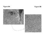
- FIG. 9A shows a picture of a face.
- FIG. 9B shows a close up of the face in FIG. 9A wherein the “small dark” pixels shown in FIG. 9B are used to calculate a weighed index using bilinear interpolation.
- FIGS. 10A-D show searching for a Best Fit on the Error Surface:
- An error surface calculation in the Gradient Descent Search method involves calculating mean squared differences of pixels in the square fit box centered on reference image pixel (x0, y0), between the reference image frame and the corresponding (offset) location (x, y) on the search image frame.
- FIGS. 11A-C show a second search box derived from a descent down the error surface gradient (evaluated separately), for which the evaluated error function is reduced, possibly minimized, with respect to the original reference box (evident from visual comparison of the boxes with the reference box in FIGS. 10A , B, C and D.).
- FIG. 12 depicts the gradient component evaluation.
- the error surface gradient is calculated as per definition of the gradient. Vertical and horizontal error deviations are evaluated at four positions near the search box center position, and combined to provide an estimate of the error gradient for that position. 12 .
- FIG. 13 shows a propagated mask in the first sequential instance where there is little discrepancy between the underlying image data and the mask data.
- the dress mask and hand mask can be clearly seen to be off relative to the image data.
- FIG. 14 shows that by using the automatic mask fitting routine, the mask data adjusts to the image data by referencing the underlying image data in the preceding image.
- FIG. 15 shows the mask data in later images within the sequence show marked discrepancy relative to the underlying image data. Eye makeup, lipstick, blush, hair, face, dress and hand image data are all displaced relative to the mask data.
- FIG. 16 shows that the mask data is adjusted automatically based on the underlying image data from the previous mask and underlying image data.
- FIG. 17 shows the mask data from FIG. 16 is shown with appropriate color transforms after whole frame automatic mask fitting.
- the mask data is adjusted to fit the underlying luminance pattern based on data from the previous frame or from the initial key frame.
- FIG. 18 shows polygons that are used to outline a region of interest for masking in frame one.
- the square polygon points snap to the edges of the object of interest.
- the Bezier points snap to the object of interest and the control points/curves shape to the edges.
- FIG. 19 shows the entire polygon or Bezier curve is carried to a selected last frame in the display memory where the operator adjusts the polygon points or Bezier points and curves using the snap function which automatically snaps the points and curves to the edges of the object of interest.
- FIG. 20 shows that if there is a marked discrepancy between the points and curves in frames between the two frames where there was an operator interactive adjustment, the operator will further adjust a frame in the middle of the plurality of frames where there is maximum error of fit.
- FIG. 21 shows that when it is determined that the polygons or Bezier curves are correctly animating between the two adjusted frames, the appropriate masks are applied to all frames.
- FIG. 22 shows the resulting masks from a polygon or Bezier animation with automatic point and curve snap to edges.
- the brown masks are the color transforms and the green masks are the arbitrary color masks.
- FIG. 23 shows an example of two pass blending:
- the objective in two-pass blending is to eliminate moving objects from the final blended mosaic. This can be done by first blending the frames so the moving object is completely removed from the left side of the background mosaic. As shown in FIG. 23 , the character can is removed from the scene, but can still be seen in the right side of the background mosaic.
- FIG. 24 shows the second pass blend.
- a second background mosaic is then generated, where the blend position and width is used so that the moving object is removed from the right side of the final background mosaic.
- the character can is removed from the scene, but can still be seen the left side of the background mosaic.
- the moving character is shown on the left.
- FIG. 25 shows the final background corresponding to FIGS. 23-24 .
- the two-passes are blended together to generate the final blended background mosaic with the moving object removed from the scene.
- the final blended background with moving character is removed.
- FIG. 26 shows an edit frame pair window.
- FIG. 27 shows sequential frames representing a camera pan that are loaded into memory.
- the motion object (butler moving left to the door) has been masked with a series of color transform information leaving the background black and white with no masks or color transform information applied.
- FIG. 28 shows six representative sequential frames of the pan above are displayed for clarity.
- FIG. 29 shows the composite or montage image of the entire camera pan that was built using phase correlation techniques.
- the motion object (butler) included as a transparency for reference by keeping the first and last frame and averaging the phase correlation in two directions.
- the single montage representation of the pan is color designed using the same color transform masking techniques as used for the foreground object.
- FIG. 30 shows that the sequence of frames in the camera pan after the background mask color transforms the montage has been applied to each frame used to create the montage.
- the mask is applied where there is no pre-existing mask thus retaining the motion object mask and color transform information while applying the background information with appropriate offsets.
- FIG. 31 shows a selected sequence of frames in the pan for clarity after the color background masks have been automatically applied to the frames where there is no pre-existing masks.
- FIG. 32 shows a sequence of frames in which all moving objects (actors) are masked with separate color transforms.
- FIG. 33 shows a sequence of selected frames for clarity prior to background mask information. All motion elements have been fully masked using the automatic mask-fitting algorithm.
- FIG. 34 shows the stationary background and foreground information minus the previously masked moving objects.
- the single representation of the complete background has been masked with color transforms in a manner similar to the motion objects.
- outlines of removed foreground objects appear truncated and unrecognizable due to their motion across the input frame sequence interval, i.e., the black objects in the frame represent areas in which the motion objects (actors) never expose the background and foreground.
- the black objects are ignored during the masking operation in colorization-only projects because the resulting background mask is later applied to all frames used to create the single representation of the background only where there is no pre-existing mask.
- the missing data area may be displayed so that image data may be obtained/generated for the missing data area so as to provide visually believable image data when translating foreground objects horizontally to generate a second viewpoint.
- FIG. 35 shows the sequential frames in the static camera scene cut after the background mask information has been applied to each frame with appropriate offsets and where there is no pre-existing mask information.
- FIG. 36 shows a representative sample of frames from the static camera scene cut after the background information has been applied with appropriate offsets and where there is no pre-existing mask information.
- FIGS. 37A-C show embodiments of the Mask Fitting functions, including calculate fit grid and interpolate mask on fit grid.
- FIGS. 38A-B show embodiments of the extract background functions.
- FIGS. 39A-C show embodiments of the snap point functions.
- FIGS. 40A-C show embodiments of the bimodal threshold masking functions, wherein FIG. 40C corresponds to step 2 . 1 in FIG. 40A , namely “Create Image of Light/Dark Cursor Shape” and FIG. 40B corresponds to step 2 . 2 in FIG. 40A , namely “Apply Light/Dark shape to mask”.
- FIGS. 41A-B show embodiments of the calculate fit value functions.
- FIG. 42 shows two image frames that are separated in time by several frames, of a person levitating a crystal ball wherein the various objects in the image frames are to be converted from two-dimensional objects to three-dimensional objects.
- FIG. 43 shows the masking of the first object in the first image frame that is to be converted from a two-dimensional image to a three-dimensional image.
- FIG. 44 shows the masking of the second object in the first image frame.
- FIG. 45 shows the two masks in color in the first image frame allowing for the portions associated with the masks to be viewed.
- FIG. 46 shows the masking of the third object in the first image frame.
- FIG. 47 shows the three masks in color in the first image frame allowing for the portions associated with the masks to be viewed.
- FIG. 48 shows the masking of the fourth object in the first image frame.
- FIG. 49 shows the masking of the fifth object in the first image frame.
- FIG. 50 shows a control panel for the creation of three-dimensional images, including the association of layers and three-dimensional objects to masks within an image frame, specifically showing the creation of a Plane layer for the sleeve of the person in the image.
- FIG. 51 shows a three-dimensional view of the various masks shown in FIGS. 43-49 , wherein the mask associated with the sleeve of the person is shown as a Plane layer that is rotated toward the left and right viewpoints on the right of the page.
- FIG. 52 shows a slightly rotated view of FIG. 51 .
- FIG. 53 shows a slightly rotated view of FIG. 51 .
- FIG. 54 shows a control panel specifically showing the creation of a sphere object for the crystal ball in front of the person in the image.
- FIG. 55 shows the application of the sphere object to the flat mask of the crystal ball, which is shown within the sphere and as projected to the front and back of the sphere to show the depth assigned to the crystal ball.
- FIG. 56 shows a top view of the three-dimensional representation of the first image frame showing the Z-dimension assigned to the crystal ball shows that the crystal ball is in front of the person in the scene.
- FIG. 57 shows that the sleeve plane rotating in the X-axis to make the sleeve appear to be coming out of the image more.
- FIG. 58 shows a control panel specifically showing the creation of a Head object for application to the person's face in the image, i.e., to give the person's face realistic depth without requiring a wire model for example.
- FIG. 59 shows the Head object in the three-dimensional view, too large and not aligned with the actual person's head.
- FIG. 60 shows the Head object in the three-dimensional view, resized to fit the person's face and aligned, e.g., translated to the position of the actual person's head.
- FIG. 61 shows the Head object in the three-dimensional view, with the Y-axis rotation shown by the circle and Y-axis originating from the person's head thus allowing for the correct rotation of the Head object to correspond to the orientation of the person's face.
- FIG. 62 shows the Head object also rotated slightly clockwise, about the Z-axis to correspond to the person's slightly tilted head.
- FIG. 63 shows the propagation of the masks into the second and final image frame.
- FIG. 64 shows the original position of the mask corresponding to the person's hand.
- FIG. 65 shows the reshaping of the mask, that can be performed automatically and/or manually, wherein any intermediate frames get the tweened depth information between the first image frame masks and the second image frame masks.
- FIG. 66 shows the missing information for the left viewpoint as highlighted in color on the left side of the masked objects in the lower image when the foreground object, here a crystal ball is translated to the right.
- FIG. 67 shows the missing information for the right viewpoint as highlighted in color on the right side of the masked objects in the lower image when the foreground object, here a crystal ball is translated to the left.
- FIG. 68 shows an anaglyph of the final depth enhanced first image frame viewable with Red/Blue 3-D glasses.
- FIG. 69 shows an anaglyph of the final depth enhanced second and last image frame viewable with Red/Blue 3-D glasses, note rotation of person's head, movement of person's hand and movement of crystal ball.
- FIG. 70 shows the right side of the crystal ball with fill mode “smear”, wherein the pixels with missing information for the left viewpoint, i.e., on the right side of the crystal ball are taken from the right edge of the missing image pixels and “smeared” horizontally to cover the missing information.
- FIG. 71 shows a mask or alpha plane, for an actor's upper torso and head (and transparent wings).
- the mask may include opaque areas shown as black and transparent areas that are shown as grey areas.
- FIG. 72 shows an occluded area, that corresponds to the actor of FIG. 71 , and that shows an area of the background that is never exposed in any frame in a scene. This may be a composite background for example.
- FIG. 73 shows the occluded area artistically rendered to generate a complete and realistic background for use in two-dimensional to three-dimensional conversion, so as to enable an artifact-free conversion.
- FIG. 73A shows the occluded area partially drawn or otherwise rendered to generate just enough of a realistic looking background for use in minimizing artifacts two-dimensional to three-dimensional conversion.
- FIG. 74 shows a light area of the shoulder portion on the right side of FIG. 71 that represents a gap where stretching (as is also shown in FIG. 70 ) would be used when shifting the foreground object to the left to create a right viewpoint.
- the dark portion of the figure is taken from the background where data is available in at least one frame of a scene.
- FIG. 75 shows an example of the stretching of pixels, i.e., smearing, corresponding to the light area in FIG. 74 without the use of a generated background, i.e., if no background data is available for an area that is occluded in all frames of a scene.
- FIG. 76 shows a result of a right viewpoint without artifacts on the edge of the shoulder of the person wherein the dark area includes pixels available in one or more frames of a scene, and generated data for always-occluded areas of a scene.
- FIG. 77 shows an example of a computer-generated element, here a robot, which is modeled in three-dimensional space and projected as a two-dimensional image. If metadata such as alpha, mask, depth or any combination thereof exists, the metadata can be utilized to speed the conversion process from two-dimensional image to a pair of two-dimensional images for left and right eye for three-dimensional viewing.
- metadata such as alpha, mask, depth or any combination thereof exists
- FIG. 78 shows an original image separated into a background and foreground elements, (mountain and sky in the background and soldiers in the bottom left also see FIG. 79 ) along with the imported color and depth of the computer-generated element, i.e., the robot with depth automatically set via the imported depth metadata.
- the computer-generated element i.e., the robot with depth automatically set via the imported depth metadata.
- any area that is covered for the scene can be artistically rendered for example to provide believable missing data, as is shown in FIG. 73 based on the missing data of FIG. 73A , which results in artifact free edges as shown in FIG. 76 for example.
- FIG. 79 shows masks associated with the photograph of soldiers in the foreground to apply depth to the various portions of the soldiers that lie in depth in front of the computer-generated element, i.e., the robot.
- the dashed lines horizontally extending from the mask areas show horizontal translation of the foreground objects takes place and where imported metadata can be utilized to accurately auto-correct over-painting of depth or color on the masked objects when metadata exists for the other elements of a movie. For example, when an alpha exists for the objects that occur in front of the computer-generated elements.
- One type of file that can be utilized to obtain mask edge data is a file with alpha file and/or mask data such as an RGBA file.
- FIG. 80 shows an imported alpha layer which can also be utilized as a mask layer to limit the operator defined, and potentially less accurate masks used for applying depth to the edges of the three soldiers A, B and C.
- a computer-generated element for dust or a dust layer image for example can be inserted into the scene along the line annotated as “DUST”, to augment the reality of the scene.
- FIG. 81 shows the result of using the operator-defined masks without adjustment when overlaying a motion element such as the soldier on the computer-generated element such as the robot.
- FIG. 82 shows a view of a software program configured to execute on a computer system that shows interface elements on the left side of the screen for altering characteristics of the input image over a series of frames that are shown on the bottom portion of the window.
- a translucent layer is imported and displayed in 3-D space in the right portion of the window.
- the translucent lay may for example include any type of translucent matter, e.g., smoke, haze or fog, etc., with no depth information.
- the translucent layer may not show the translucent element's shape since the colors of the element may be subtle or nearly transparent for example and difficult to see without false coloring.
- FIG. 83 shows application of depth, and display thereof to the pixels in the layer having a certain color or alpha value or which may be differentiated from other image elements such as background elements or other motion elements.
- a value range for luminance or color or alpha is utilized to set portions of the translucent element as closer (toward the viewpoint shown at the apex of the two pyramids that represent the right and left eye viewpoints) or further away (away from the apex of the two pyramids toward the left side of the window as shown).
- FIG. 84 shows application of a different color range to extend the depth of the layer with respect to FIG. 83 .
- FIG. 85 shows the display of a false color or mask view of the translucent element by displaying portions of the layer having a different characteristic, i.e., luminance, color, alpha, etc., in at least one color while displaying portions of the layer not having these characteristics in a different color.
- a different characteristic i.e., luminance, color, alpha, etc.
- FIG. 86 shows a different frame in the sequence of images where the translucent element is shaped differently wherein tweening may be utilized to morph the shape and depth of the translucent region between any two desired frames. This enables minimal work in setting depth to a translucent element in a layer.
- FIG. 87 shows depth modification parameters in the left portion of the window that may be utilized to vary depth within the translucent element.
- FIG. 88 shows a different setting for the blur radius so that the depth settings for the translucent region may have smoother or sharper depth profiles.
- FIG. 89 shows setting of depth lines with respect to FIG. 86 which enables shapes effectively to be applied to the depth profile to morph the shape of the translucent area.
- FIG. 90 shows a portion of an image having falling snow, which may for example be obtained by time masking by obtaining the average value of pixels in a scene and differencing each image in the scene from the average.
- FIG. 91 shows depth setting on a range of colors for example in the falling snow.
- FIG. 92 shows a display of the depth added to the snowflake based on luminance.
- FIG. 93 shows a depth range modification with respect to FIG. 92 to pull the lower portion of the snowflake closer.
- Feature films are tele-cined or transferred from 35 mm or 16 mm film using a high resolution scanner such as a 10-bit SPIRIT DATACINE® or similar device to HDTV (1920 by 1080 24P) or data-cined on a laser film scanner such as that manufactured by IMAGICA® Corp. of America at a larger format 2000 lines to 4000 lines and up to 16 bits of grayscale.
- the high resolution frame files are then converted to standard digital files such as uncompressed TIP files or uncompressed TGA files typically in 16 bit three-channel linear format or 8 bit three channel linear format.
- the 10-bit HDTV frame files are converted to similar TIF or TGA uncompressed files at either 16-bits or 8-bit per channel. Each frame pixel is then averaged such that the three channels are merged to create a single 16 bit channel or 8 bit channel respectively.
- Any other scanning technologies capable of scanning an existing film to digital format may be utilized.
- many movies are generated entirely in digital format, and thus may be utilized without scanning the movie.
- the metadata can be imported for example to obtain an alpha and/or mask and/or depth for the computer-generated element on a pixel-by-pixel or sub-pixel-by-sub-pixel basis.
- One format of a file that contains alpha/mask and depth data is the RGBAZ file format, of which one implementation is the EXR file format.
- Monochrome elements of either 35 or 16 mm negative or positive film are digitized at various resolutions and bit depth within a high resolution film scanner such as that performed with a SPIRIT DATACINE® by PHILIPS® and EASTMAN KODAK® which transfers either 525 or 625 formats, HDTV, (HDTV) 1280 ⁇ 720/60 Hz progressive, 2K, DTV (ATSC) formats like 1920 ⁇ 1080/24 Hz/25 Hz progressive and 1920 ⁇ 1080/48 Hz/50 Hz segmented frame or 1920 ⁇ 1080 50I as examples.
- the invention provides improved methods for editing film into motion pictures.
- Visual images are transferred from developed motion picture film to a high definition video storage medium, which is a storage medium adapted to store images and to display images in conjunction with display equipment having a scan density substantially greater than that of an NTSC compatible video storage medium and associated display equipment.
- the visual images are also transferred, either from the motion picture film or the high definition video storage medium to a digital data storage format adapted for use with digital nonlinear motion picture editing equipment.
- the digital nonlinear motion picture editing equipment is used to generate an edit decision list, to which the motion picture film is then conformed.
- the high definition video storage medium is generally adapted to store and display visual images having a scan density of at least 1080 horizontal lines.
- Electronic or optical transformation may be utilized to allow use of visual aspect ratios that make full use of the storage formats used in the method.
- This digitized film data as well as data already transferred from film to one of a multiplicity of formats such as HDTV are entered into a conversion system such as the HDTV STILL STORE® manufactured by AVICA® Technology Corporation.
- Such large scale digital buffers and data converters are capable of converting digital image to all standard formats such as 1080i HDTV formats such as 720p, and 1080p/24.
- An Asset Management System server provides powerful local and server back ups and archiving to standard SCSI devices, C2-level security, streamlined menu selection and multiple criteria data base searches.
- An undersized third pin enters a third perforation spaced along the film from the second pin and then pulls the film obliquely to a reference line extending between the first and second pins to nest against the first and second pins the perforations thereat and register the image frame precisely at the positioning location or aperture.
- a pair of flexible bands extending along the film edges adjacent the positioning location moves progressively into incrementally increasing contact with the film to iron it and clamp its perforations against the gate.
- the pins register the image frame precisely with the positioning location, and the bands maintain the image frame in precise focal position. Positioning can be further enhanced following the precision mechanical capture of images by methods such as that embodied in U.S. Pat. No. 4,903,131, Method For The Automatic Correction Of Errors In Image Registration During Film Scanning.
- the digital movie is broken down into scenes and cuts.
- the entire movie is then processed sequentially for the automatic detection of scene changes including dissolves, wipe-a-ways and cuts.
- These transitions are further broken down into camera pans, camera zooms and static scenes representing little or no movement.
- All database references to the above are entered into an edit decision list (EDT) within the database based on standard SMPTE time code or other suitable sequential naming convention.
- Motion is broken down into simple and complex depending on occlusion elements, number of moving objects and quality of the optics (e.g., softness of the elements, etc).
- Files are numbered using sequential SMPTE time code or other sequential naming convention.
- the image files are edited together at 24-frame/sec speed (without field related 3/2 pull down which is used in standard NTSC 30 frame/sec video) onto a DVD using ADOBE® AFTER EFFECTS® or similar programs to create a running video with audio of the feature film or TV series. This is used to assist with scene analysis and scene breakdown.
- a database permits the entering of scene, cut, design, key frame and other critical data in time code format as well as descriptive information for each scene and cut.
- Single frames from each scene are selected to serve as design frames. These frames are color designed or metadata is imported for depth and/or mask and/or alpha for computer-generated elements, or depth assignments (see FIGS. 42-70 ) are made to background elements or motion elements in the frames to represent the overall look and feel of the feature film. Approximately 80 to 100 design frames are typical for a feature film.
- single frames called key frames from each cut of the feature film are selected that contain all the elements within each cut that require color/depth consideration. There may be as many as 1,000 key frames. These frames will contain all the color/depth transform information necessary to apply color/depth to all sequential frames in each cut without additional color choices.
- Historical reference, studio archives and film analysis provides the designer with color references.
- the designer uses an input device such as a mouse, the designer masks features in a selected single frame containing a plurality of pixels and assigns color to them using an HSL color space model based on creative considerations and the grayscale and luminance distribution underlying each mask.
- One or more base colors are selected for image data under each mask and applied to the particular luminance pattern attributes of the selected image feature. Each color selected is applied to an entire masked object or to the designated features within the luminance pattern of the object based on the unique gray-scale values of the feature under the mask.
- a lookup table or color transform for the unique luminance pattern of the object or feature is thus created which represent the color to luminance values applied to the object. Since the color applied to the feature extends the entire range of potential grayscale values from dark to light the designer can insure that as the distribution of the gray-scale values representing the pattern change homogeneously into dark or light regions within subsequent frames of the movie such as with the introduction of shadows or bright light, the color for each feature also remains consistently homogeneous and correctly lighten or darken with the pattern upon which it is applied.
- Depth can imported for computer-generated objects where metadata exists and/or can be assigned to objects and adjusted using embodiments of the invention using an input device such as a mouse to assign objects particular depths including contour depths, e.g., geometric shapes such as an ellipsoid to a face for example.
- contour depths e.g., geometric shapes such as an ellipsoid to a face for example.
- contour depths e.g., geometric shapes such as an ellipsoid to a face for example.
- contour depths e.g., geometric shapes such as an ellipsoid to a face for example.
- the imported depth and/or alpha and/or mask shape can be adjusted if desired. Assigning a fixed distance to foreground objects tends to make the objects appear as cut-outs, i.e., flat. See also FIGS. 42-70 .
- the masks representing designed selected color transforms/depth contours in the single design frame are then copied to all subsequent frames in the series of movie frames by one or more methods such as auto-fitting bezier curves to edges, automatic mask fitting based on Fast Fourier Transforms and Gradient Descent Calculation tied to luminance patterns in a subsequent frame relative to the design frame or a successive preceding frames, mask paint to a plurality of successive frames by painting the object within only one frame, auto-fitting vector points to edges and copying and pasting individual masks or a plurality of masks to selected subsequent frames.
- depth information may be “tweened” to account for forward/backward motion or zooming with respect to the camera capture location.
- the alpha and/or mask data is generally correct and may be skipped for reshaping processes since the metadata associated with computer-generated elements is obtained digitally from the original model of an object and hence does not require adjustment in general.
- step 3710 for setting mask fit location to border of CG element to potentially skip large amounts of processing in fitting masks in subsequent frames to reshape the edges to align a photographic element.
- computer-generated elements may be morphed or reshaped to provide special effects not originally in a movie scene.
- camera moves are consolidated and separated from motion elements in each scene by the creation of a montage or composite image of the background from a series of successive frames into a single frame containing all background elements for each scene and cut.
- the resulting single frame becomes a representation of the entire common background of a multiplicity of frames in a movie, creating a visual database of all elements and camera offset information within those frames.
- Cuts are either single occurrences or a combination of cut-a-ways where there is a return to a particular camera shot such as in a dialog between two individuals. Such cut-a-ways can be considered a single scene sequence or single cut and can be consolidate in one image-processing pass.
- Pans can be consolidated within a single frame visual database using special panorama stitching techniques but without lens compensation.
- Each frame in a pan involves:
- each pixel within a single frame visual database of a background corresponds to an appropriate address within the respective “raw” (unconsolidated) frame from which it was created, any designer determined masking operation and corresponding masking lookup table designation applied to the visual database will be correctly applied to each pixel's appropriate address within the raw film frames that were used to create the single frame composite.
- sets for each scene and cut are each represented by a single frame (the visual database) in which pixels have either single or multiple representations within the series of raw frames from which they were derived. All masking within a single visual database frame will create a one bit mask per region representation of an appropriate lookup table that corresponds to either common or unique pixel addresses within the sequential frames that created the single composite frame. These address-defined masking pixels are applied to the full resolution frames where total masking is automatically checked and adjusted where necessary using feature, edge detection and pattern recognition routines. Where adjustments are required, i.e., where applied masked region edges do not correspond to the majority of feature edges within the gray scale image, a “red flag” exception comment signals the operator that frame-by-frame adjustments may be necessary.
- the differencing algorithm used for detecting motion objects will generally be able to differentiate dramatic pixel region changes that represent moving objects from frame to frame.
- the resulting masks will be assigned to a default alpha layer that renders that part of the moving object mask transparent.
- an operator using one or more vector or paint tools will designate the demarcation between the moving object and cast shadow.
- the cast shadows will be detected as an extraneous feature relative to the two key motion objects.
- cast shadows are handled by the background lookup table that automatically adjusts color along a luminance scale determined by the spectrum of light and dark gray scale values in the image.
- Action within each frame is isolated via differencing or frame-to-frame subtraction techniques that include vector (both directional and speed) differencing (i.e., where action occurs within a pan) as well as machine vision techniques, which model objects and their behaviors. Difference pixels are then composited as a single frame (or isolated in a tiling mode) representing a multiplicity of frames thus permitting the operator to window regions of interest and otherwise direct image processing operations for computer controlled subsequent frame masking.
- action taking place in multiple frames within a scene can be represented by a single frame visual database in which each unique pixel location undergoes appropriate one bit masking from which corresponding lookup tables are applied.
- the purpose of creating an action composite visual data base is to window or otherwise designate each feature or region of interest that will receive a particular mask and apply region of interest vectors from one key frame element to subsequent key frame elements thus provide operator assistance to the computer processing that will track each region of interest.
- masks are applied to designer designated regions of interest for a single instance of a motion object appearing within the background (i.e., a single frame of action appears within the background or stitched composited background in the proper x, y coordinates within the background corresponding to the single frame of action from which it was derived).
- a single frame of action appears within the background or stitched composited background in the proper x, y coordinates within the background corresponding to the single frame of action from which it was derived.
- an input device such as a mouse the operator uses the following tools in creating the regions of interest for masking.
- projects having associated computer-generated element metadata may import and if necessary, scale the metadata to the units utilized for depth in the project. Since these masks are digitally created, they can be assumed to be accurate throughout the scene and thus the outlines and depths of the computer-generated areas may be ignored for reshaping operations.
- An operator-assisted sliding scale and other tools create a “best fit” distribution index corresponding to the dynamic range of the underlying pixels as well as the underlying luminance values, pattern and weighted variables
- Key Frame Motion Object Creation The operator windows all masked regions of interest on the design frame in succession and directs the computer by various pointing instruments and routines to the corresponding location (regions of interest) on selected key frame motion objects within the visual database thereby reducing the area on which the computer must operate (i.e., the operator creates a vector from the design frame moving object to each subsequent key frame moving object following a close approximation to the center of the region of interest represented within the visual database of the key frame moving object.
- This operator-assisted method restricts the required detection operations that must be performed by the computer in applying masks to the corresponding regions of interest in the raw frames).
- the composited key frame motion object database described above is presented along with all subsequent motion inclusive of fully masked selected key frame motion objects.
- all motion composites can be toggled on and off within the background or sequentially turned on and off in succession within the background to simulate actual motion.
- all masked regions regions of interest
- the one-bit color masks are displayed as either translucent or opaque arbitrary colors.
- each region of interest within subsequent motion object frames, between two key motion object frames undergoes a computer masking operation.
- the masking operation involves a comparison of the masks in a preceding motion object frame with the new or subsequent Detector File operation and underlying parameters (i.e., mask dimensions, gray scale values and multiple weighting factors that lie within the vector of parameters in the subsequent key frame motion object) in the successive frame.
- This process is aided by the windowing or pointing (using various pointing instruments) and vector application within the visual database.
- the computer will determine a match and will attempt a best fit.
- the uncompressed, high resolution images all reside at the server level, all subsequent masking operations on the regions of interest are displayed on the compressed composited frame in display memory or on a tiled, compressed frame in display memory so that the operator can determine correct tracking and matching of regions.
- a zoomed region of interest window showing the uncompressed region is displayed on the screen to determine visually the region of interest best fit.
- This high-resolution window is also capable of full motion viewing so that the operator can determine whether the masking operation is accurate in motion.
- FIG. 1 a plurality of feature film or television film frames 14 a - n representing a scene or cut in which there is a single instance or perceptive of a background 12 ( FIG. 3 ).
- FIG. 1 shows selected samples of the 120 total frames 14 making up the 5-second pan.
- FIG. 2 an isolated background 16 processed scene from the plurality of frames 14 a - n represented in FIG. 1 in which all motion elements 18 are removed using various subtraction and differencing techniques.
- the separate frames that created the pan are combined into a visual database in which unique and common pixels from each of the 120 frames 14 composing the original pan are represented in the single composite background image 12 shown in FIG. 3 .
- the single background image 12 is then used to create a background mask overlay 20 representing designer selected color lookup tables in which dynamic pixel colors automatically compensate or adjust for moving shadows and other changes in luminance. For depth projects, any object in the background may be assigned any depth.
- a variety of tools may be utilized to perform the assignment of depth information to any portion of the background including paint tools, geometric icon based tools that allow setting a contour depth to an object, or text field inputs to allow for numeric inputs.
- the composite background shown in FIG. 2 for example may also have a ramp function assigned to allow for a nearer depth to be assigned to the left portion of the scene and a linear increase in depth to the right of the image to be automatically assigned. See also FIGS. 42-70 .
- Any dust that may occur in the scene may also be detected using an average pixel value for each element in the scene and performing a different on individual pixels to determine the differences, which may represent dust or haze or any other translucent element.
- operator assisted and automated operations are used to detect obvious anchor points represented by clear edge detected intersects and other contiguous edges n each frame 14 making up the single composite image 12 and over laid mask 20 .
- These anchor points are also represented within the composite image 12 and are used to aide in the correct assignment of the mark to each frame 14 represented by the single composite image 12 .
- Anchor points and objects and/or areas that are clearly defined by closed or nearly closed edges are designed as a single mask area and given a single lookup table. Within those clearly delineated regions polygons are created of which anchor points are dominant points. Where there is no clear edge detected to create a perfectly closed region, polygons are generated using the edge of the applied mask.
- the resulting polygon mesh includes the interior of anchor point dominant regions plus all exterior areas between those regions.
- Pattern parameters created by the distribution of luminance within each polygon are registered in a database for reference when corresponding polygonal addresses of the overlying masks are applied to the appropriate addresses of the frames that were used to create the composite single image 12 .
- a representative sample of each motion object (M-Object) 18 in the scene 10 receives a mask overlay that represents designer selected color lookup tables/depth assignments in which dynamic pixel colors automatically compensate or adjust for moving shadows and other changes in luminance as the M-Object 18 moves within the scene 10 .
- the representative sample are each considered Key M-Objects 18 that are used to define the underlying patterns, edges, grouped luminance characteristics, etc., within the masked M-Object 18 . These characteristics are used to translate the design masks from one Key M-Object 18 a to subsequent M-Objects 18 b along a defined vector of parameters leading to Key M-Object 18 c , each Subsequent M-Object becoming the new Key M-Object in succession as masks are applied.
- Key M-Object 18 a may be assigned a depth of 32 feet from the camera capture point while Key M-Object 18 c may be assigned a depth of 28 feet from the camera capture point.
- the various depths of the object may be “tweened” between the various depth points to allow for realistic three-dimensional motion to occur within the cut without for example requiring wire frame models of all of the objects in the objects in a frame.
- operator assisted and automated operations are used to detect obvious anchor points represented by clear edge detected intersects and other contiguous edges in each motion object used to create a keyframe.
- Anchor points and specific regions of interest within each motion object that are clearly defined by closed or nearly closed edges are designated as a single mask area and given a single lookup table. Within those clearly delineated regions, polygons are created of which anchor points are dominant points. Where there is no clear edge detected to create a perfectly closed region, polygons are generated using the edge of the applied mask.
- the resulting polygon mesh includes the interior of the anchor point dominant regions plus all exterior areas between those regions.
- Pattern parameters created by the distribution of luminance values within each polygon are registered in a database for reference when corresponding polygonal addresses of the overlying masks are applied to the appropriate addresses of the frames that were used to create the composite single frame 12 .
- Subsequent or in-between motion key frame objects 18 are processed sequentially.
- the group of masks comprising the motion key frame object remains in its correct address location in the subsequent frame 14 or in the subsequent instance of the next motion object 18 .
- the mask is shown as an opaque or transparent color.
- An operator indicates each mask in succession with a mouse or other pointing device and along with its corresponding location in the subsequent frame and/or instance of the motion object.
- the computer uses the prior anchor point and corresponding polygons representing both underlying luminance texture and mask edges to create a best fit to the subsequent instance of the motion object.
- the next instance of the motion object 18 is operated upon in the same manner until all motion objects 18 in a cut 10 and/or scene are completed between key motion objects.
- all mask elements of the scene 10 are then rendered to create a fully colored and/or depth enhanced frame in which M-Object 18 masks are applied to each appropriate frame in the scene followed by the background mask 20 , which is applied only where there is no pre-existing mask in a Boolean manner.
- Foreground elements are then applied to each frame 14 according to a pre-programmed priority set. Aiding the accurate application of background masks 20 are vector points which are applied by the designer to the visual database at the time of masking where there are well defined points of reference such as edges and/or distinct luminance points. These vectors create a matrix of reference points assuring accuracy of rendering masks to the separate frames that compose each scene.
- the applied depths of the various objects determine the amount of horizontal translation applied when generating left and right viewpoints as utilized in three-dimensional viewing as one skilled in the art will appreciate.
- the desired objects may be dynamically displayed while shifting by an operator set and observe a realistic depth.
- the depth value of an object determines the horizontal shift applied as one skilled in the art will recognize and which is taught in at least U.S. Pat. No. 6,031,564, to Ma et al., the specification of which is hereby incorporated herein by reference.
- each of the masked objects may have a depth shape applied, so that the object is three-dimensional as will be described further below.
- the operator employs several tools to apply masks to successive movie frames.
- a key frame that includes all motion objects for that frame is fully masked and loaded into the display buffer along with a plurality of subsequent frames in thumbnail format; typically 2 seconds or 48 frames.
- FIGS. 5A and 5B show a series of sequential frames 14 a - n loaded into display memory in which one frame 14 is fully masked with the background (key frame) and ready for mask propagation to the subsequent frames 14 via automatic mask fitting methods.
- All frames 14 along with associated masks and/or applied color transforms/depth enhancements can also be displayed sequentially in real-time (24 frames/sec) using a second (child) window to determine if the automatic masking operations are working correctly.
- stereoscopic glasses or red/blue anaglyph glasses may be utilized to view both viewpoints corresponding to each eye. Any type of depth viewing technology may be utilized to view depth enhanced images including video displays that require no stereoscopic glasses yet which utilizes more than two image pairs which may be created utilizing embodiments of the invention.
- FIGS. 6A and 6B show the child window displaying an enlarged and scalable single image of the series of sequential images in display memory.
- the Child window enables the operator to manipulate masks interactively on a single frame or in multiple frames during real time or slowed motion.
- Masks can be copied to all or selected frames and automatically modified in thumbnail view or in the preview window. In the preview window mask modification takes place on either individual frames in the display or on multiple frames during real-time motion.
- a single mask (flesh) is propagated automatically to all frames 14 in the display memory.
- the operator could designate selective frames to apply the selected mask or indicate that it is applied to all frames 14 .
- the mask is a duplication of the initial mask in the first fully masked frame. Modifications of that mask occur only after they have been propagated.
- all masks associated with the motion object are propagated to all sequential frames in display memory.
- the images show the displacement of the underlying image data relative to the mask information.
- Masks are adjusted to compensate for object motion in subsequent frames using various tools based on luminance, pattern and edge characteristics of the image.
- Successive frames of a feature film or TV episode exhibit movement of actors and other objects. These objects are designed in a single representative frame within the current embodiment such that operator selected features or regions have unique color transformations identified by unique masks, which encompass the entire feature.
- the purpose of the mask-fitting tool is to provide an automated means for correct placement and reshaping of a each mask region of interest (ROI) in successive frames such that the mask accurately conforms to the correct spatial location and two dimensional geometry of the ROI as it displaces from the original position in the single representative frame.
- This method is intended to permit propagation of a mask region from an original reference or design frame to successive frames, and automatically enabling it to adjust shape and location to each image displacement of the associated underlying image feature.
- the associated masks are digitally created and can be assumed to be accurate throughout the scene and thus the outlines and depths of the computer-generated areas may be ignored for automatic mask fitting or reshaping operations. Elements that border these objects, may thus be more accurately reshaped since the outlines of the computer-generated elements are taken as correct.
- the shape of the mask at the junction can be taken to be accurate even though there is no visual difference at the junction.
- the computer-generated element mask can be utilized to define the border of the operator-defined mask as per step 3710 of FIG. 37C .
- Automated mask fitting on translucent objects in subsequent frames may also utilize underlying values in the image, such as luminance or color, or may utilize any other values associated with the translucent object such as an alpha value associated with a portion of a layer that is associated with the translucent element for example.
- the method for automatically modifying both the location and correctly fitting all masks in an image to compensate for movement of the corresponding image data between frames involves the following:
- a reference frame (frame 1) is masked by an operator using a variety of means such as paint and polygon tools so that all regions of interest (i.e., features) are tightly covered.
- the minimum and maximum x,y coordinate values of each masked region are calculated to create rectangular bounding boxes around each masked region encompassing all underlying image pixels of each masked region.
- a subset of pixels are identified for each region of interest within its bounding rectangle (i.e., every 10th pixel)
- FFT Fast Fourier Transform
- Each mask in frame 2 with the accompanying bounding boxes are moved to compensate for the displacement of corresponding image data from frame 1 using the FFT calculation.
- the bounding box is augmented by an additional margin around the region to accommodate other motion and shape morphing effects.
- Mask fit initialization An operator selects image features in a single selected frame of a scene (the reference frame) and creates masks with contain all color transforms (color lookup tables) for the underlying image data for each feature.
- the selected image features that are identified by the operator have well-defined geometric extents which are identified by scanning the features underlying each mask for minimum and maximum x, y coordinate values, thereby defining a rectangular bounding box around each mask.
- the Fit Grid used for Fit Grid Interpolation For optimization purposes, only a sparse subset of the relevant mask-extent region pixels within each bounding box are fit with the method; this subset of pixels defines a regular grid in the image, as labeled by the light pixels of FIG. 9A .
- the “small dark” pixels shown in FIG. 9B are used to calculate a weighed index using bilinear interpolation.
- the grid spacing is currently set at 10 pixels, so that essentially no more than 1 in 50 pixels are presently fit with a gradient descent search. This grid spacing could be a user controllable parameter.
- FFT Fast Fourier Transform
- the FFT provides a displacement vector, which directs the search for ideal mask fitting using the Gradient Descent Search method.
- Gradient descent search requires that the translation or offset be less than the radius of the basin surrounding the minimum of the matching error surface. A successful FFT correlation for each mask region and bounding box will create the minimum requirements.
- An error surface calculation in the Gradient Descent Search method involves calculating mean squared differences of pixels in the square fit box centered on reference image pixel (x0, y0), between the reference image frame and the corresponding (offset) location (x, y) on the search image frame, as shown in FIGS. 10A , B, C and D.
- Fit Value Gradient The displacement vector data derived from the FFT creates a search fit location, and the error surface calculation begins at that offset position, proceeding down (against) the gradient of the error surface to a local minimum of the surface, which is assumed to be the best fit
- This method finds best fit for each next frame pixel or groups of pixels based on the previous frame, using normalized squared differences, for instance in a 10 ⁇ 10 box and finding a minimum down the mean squared difference gradients. This technique is similar to a cross correlation but with a restricted sampling box for the calculation. In this way the corresponding fit pixel in the previous frame can be checked for its mask index, and the resulting assignment is complete.
- FIGS. 11A , B and C show a second search box derived from a descent down the error surface gradient (evaluated separately), for which the evaluated error function is reduced, possibly minimized, with respect to the original reference box (evident from visual comparison of the boxes with the reference box in FIGS. 10A , B, C and D.).
- the error surface gradient is calculated as per definition of the gradient. Vertical and horizontal error deviations are evaluated at four positions near the search box center position, and combined to provide an estimate of the error gradient for that position.
- the gradient component evaluation is explained with the help of FIG. 12 .
- the reference image utilized for mask fitting is usually an adjacent frame in a film image-frame sequence. However, it is sometimes preferable to use an adequately fit mask as a reference image (e.g. a key frame mask, or the source frame from which mask regions were propagated/copied).
- the present embodiment provides a switch to disable “adjacent” reference frames, using the propagated masks of the reference image if that frame is defined by a recent propagation event.
- the process of mask fitting In the present embodiment the operator loads n frames into the display buffer. One frame includes the masks that are to be propagated and fitted to all other frames. All or some of the mask(s) are then propagated to all frames in the display buffer. Since the mask-fitting algorithm references the preceding frame or the first frame in the series for fitting masks to the subsequent frame, the first frame masks and/or preceding masks must be tightly applied to the objects and/or regions of interest. If this is not done, mask errors will accumulate and mask fitting will break down.
- the operator displays the subsequent frame, adjusts the sampling radius of the fit and executes a command to calculate mask fitting for the entire frame.
- the execution command can be a keystroke or mouse-hotkey command.
- FIG. 14 shows that by using the automatic mask fitting routine, the mask data adjusts to the image data by referencing the underlying image data in the preceding image.
- the mask data in later images within the sequence show marked discrepancy relative to the underlying image data.
- Eye makeup, lipstick, blush, hair, face, dress and hand image data are all displaced relative to the mask data.
- the mask data is adjusted automatically based on the underlying image data from the previous mask and underlying image data.
- the mask data is shown with random colors to show the regions that were adjusted automatically based on underlying pattern and luminance data.
- the blush and eye makeup did not have edge data to reference and were auto-adjusted on the basis of luminance and grayscale pattern.
- FIG. 17 mask data from FIG. 16 is shown with appropriate color transforms after whole frame automatic mask fitting.
- the mask data is adjusted to fit the underlying luminance pattern based on data from the previous frame or from the initial key frame.
- Masks for motion objects can be animated using either bezier curves or polygons that enclose a region of interest.
- a plurality of frames are loaded into display memory and either bezier points and curves or polygon points are applied close to the region of interest where the points automatically snap to edges detected within the image data.
- the operator adjusts the polygon or bezier in the last frame of the frames loaded in display memory.
- the operator executes a fitting routine, which snaps the polygons or bezier points plus control curves to all intermediate frames, animating the mask over all frames in display memory.
- the polygon and bezier algorithms include control points for rotation, scaling and move-all to handle camera zooms, pans and complex camera moves.
- polygons are used to outline a region of interest for masking in frame one.
- the square polygon points snap to the edges of the object of interest.
- the bezier points snap to the object of interest and the control points/curves shape to the edges.
- the entire polygon or bezier curve is carried to a selected last frame in the display memory where the operator adjusts the polygon points or bezier points and curves using the snap function, which automatically snaps the points and curves to the edges of the object of interest.
- FIG. 22 shows the resulting masks from a polygon or bezier animation with automatic point and curve snap to edges.
- the brown masks are the color transforms and the green masks are the arbitrary color masks.
- areas that have been depth assigned may be of one color while those areas that have yet to be depth assigned may be of another color for example.
- Embodiments of the invention include a method and process for automatically colorizing/depth enhancing a plurality of frames in scenes cuts that include complex camera movements as well as scene cuts where there is camera weave or drifting cameras movement that follows erratic action of the motion objects.
- a pan camera sequence For a pan camera sequence, the background associated with non-moving objects in a scene form a large part of the sequence.
- a mosaic that includes the background objects for an entire pan sequence with moving objects removed is created. This task is accomplished with a pan background stitcher tool. Once a background mosaic of the pan sequence is generated, it can be colorized/depth enhanced once and applied to the individual frames automatically, without having to manually colorize/depth assign the background objects in each frame of the sequence.
- the pan background stitcher tool generates a background image of a pan sequence using two general operations.
- First, the movement of the camera is estimated by calculating the transformation needed to align each frame in the sequence with the previous frame. Since moving objects form a large portion of cinematic sequences, techniques are used that minimize the effects of moving objects on the frame registration.
- Second, the frames are blended into a final background mosaic by interactively selecting two pass blending regions that effectively remove moving objects from the final mosaic.
- Background composite output data includes a greyscale/(or possibly color for depth projects) image file of standard digital format such as TIFF image file (bkg.*.tif) comprised of a background image of the entire pan shot, with the desired moving objects removed, ready for color design/depth assignments using the masking operations already described, and an associated background text data file needed for background mask extraction after associated background mask/colorization/depth data components (bkg.*.msk, bkg.*lut, . . . ) have been established.
- TIFF image file bkg.*.tif
- the background text data file provides filename, frame position within the mosaic, and other frame-dimensioning information for each constituent (input) frame associated with the background, with the following per line (per frame) content: Frame-filename, frame-x-position, frame-y-position, frame-width, frame-height, frame-left-margin-x-max, frame-right-margin-x-min.
- Each of the data fields are integers except for the first (frame-filename), which is a string.
- the registration method used in the pan stitcher uses properties of the Fourier transform in order to avoid bias towards moving objects in the scene. Automatic registration of frame pairs is calculated and used for the final background image assembly.
- the first step in the image registration process consists of taking the Fourier transform of each image.
- the camera motion can be estimated as a translation.
- Phase Shift Calculation The next step involves calculating the phase shift between the images. Doing this results in an expression for the phase shift in terms of the Fourier transform of the first and second image:
- Peak Location The two-dimensional surface that results from (4) will have a maximum peak at the translation point from the first image to the second image. By searching for the largest value in the surface, it is simple to find the transform that represents the camera movement in the scene. Although there will be spikes present due to moving objects, the dominant motion of the camera should represent the largest peak value. This calculation is performed for every consecutive pair of frames in the entire pan sequence.
- pan background stitcher deals with these outliers using two methods that detect and correct erroneous cases: closest peak matching and interpolated positions. If these corrections fail for a particular image pair, the stitching application has an option to manually correct the position of any pair of frames in the sequence.
- the frames can be composited into a mosaic which represents the entire background for the sequence. Since the moving objects in the scene need to be removed, different image blending options are used to effectively remove the dominant moving objects in the sequence.
- a background image buffer is generated which is large enough to span the entire sequence.
- the background can be blended together in a single pass, or if moving objects need to be removed, a two-pass blend is used, which is detailed below.
- the position and width of the blend can be edited in the stitching application and can be set globally set or individually set for each frame pair. Each blend is accumulated into the final mosaic and then written out as a single image file.
- Two Pass Blending The objective in two-pass blending is to eliminate moving objects from the final blended mosaic. This can be done by first blending the frames so the moving object is completely removed from the left side of the background mosaic. An example is shown in FIG. 23 , where the character can is removed from the scene, but can still be seen in the right side of the background mosaic. FIG. 23 . In the first pass blend shown in FIG. 23 , the moving character is shown on the stairs to the right
- a second background mosaic is then generated, where the blend position and width is used so that the moving object is removed from the right side of the final background mosaic.
- An example of this is shown in FIG. 24 , where the character can is removed from the scene, but can still be seen the left side of the background mosaic.
- the moving character is shown on the left.
- the two-passes are blended together to generate the final blended background mosaic with the moving object removed from the scene.
- the final background corresponding to FIGS. 23 and 24 is shown in FIG. 25 .
- the final blended background with moving character is removed.
- the stitcher application has on option to interactively set the blending width and position for each pass and each frame individually or globally.
- An example screen shot from the blend editing tool, showing the first and second pass blend positions and widths, can be seen in FIG. 26 , which is a screen shot of the blend-editing tool.
- each text data record includes: Frame-filename frame-x-position frame-y-position frame-width frame-height frame-left-margin-x-max frame-right-margin-x-min.
- the output text data filename is composed from the first composite input frame rootname by prepending the “bkg.” prefix and appending the “.txt” extension.
- Example Representative lines output text data file called “bkgA.00233.txt” that may include data from 300 or more frames making up the blended image:
- Image offset information used to create the composite representation of the series of frames is contained within a text file associated with the composite image and used to apply the single composite mask to all the frames used to create the composite image.
- FIG. 27 sequential frames representing a camera pan are loaded into memory.
- the motion object (butler moving left to the door) has been masked with a series of color transform information leaving the background black and white with no masks or color transform information applied.
- the motion object may be assigned a depth and/or depth shape. See FIGS. 42-70 .
- FIG. 28 six representative sequential frames of the pan above are displayed for clarity.
- FIG. 29 show the composite or montage image of the entire camera pan that was built using phase correlation techniques.
- the motion object (butler) included as a transparency for reference by keeping the first and last frame and averaging the phase correlation in two directions.
- the single montage representation of the pan is color designed using the same color transform masking techniques as used for the foreground object.
- FIG. 30 shows that the sequence of frames in the camera pan after the background mask color transforms the montage has been applied to each frame used to create the montage.
- the mask is applied where there is no pre-existing mask thus retaining the motion object mask and color transform information while applying the background information with appropriate offsets.
- the left and right eye views of each frame may be shown as pairs, or in a separate window for each eye for example.
- the images may be displayed on a three-dimensional viewing display as well.
- FIG. 31 a selected sequence of frames in the pan for clarity after the color background/depth enhanced background masks have been automatically applied to the frames where there is no pre-existing masks.
- Static and drifting camera shots Objects which are not moving and changing in a film scene cut can be considered “background” objects, as opposed to moving “foreground” objects. If a camera is not moving throughout a sequence of frames, associated background objects appear to be static for the sequence duration, and can be masked and colorized only once for all associated frames. This is the “static camera” (or “static background”) case, as opposed to the moving (e.g. panning) camera case, which requires stitching tool described above to generate a background composite.
- Cuts or frame sequences involving little or no camera motion provide the simplest case for generating frame-image background “composites” useful for cut background colorization.
- the static background composition tool cannot assume perfect pixel alignment from frame-to-frame, requiring an assessment of inter-frame shifts, accurate to 1 pixel, in order to optimally associated pixels between frames prior to adding their data contribution into the composite (an averaged value).
- the Static Background Composite tool provides this capability, generating all the data necessary to later colorize and extract background colorization information for each of the associated frames.
- Moving foreground objects such as actors, etc.
- the masked moving object exposes the background or foreground the instance of background and foreground previously occluded is copied into the single image with priority and proper offsets to compensate for movement.
- the offset information is included in a text file associated with the single representation of the background so that the resulting mask information can be applied to each frame in the scene cut with proper mask offsets.
- Background composite output data uses a greyscale TIFF image file (bkg.*.tif) that includes averaged input background pixel values lending itself to colorization/depth enhancement, and an associated background text data file required for background mask extraction after associated background mask/colorization data/depth enhancement components (bkg.*.msk, bkg.*.lut, . . . ) have been established.
- Background text data provides filename, mask-offset, and other frame-dimensioning information for each constituent (input) frame associated with the composite, with the following per line (per frame) format: Frame-filename frame-x-offset frame-y-offset frame-width frame-height frame-left-margin-x-max frame-right-margin-x-min. Each of these data fields are integers except for the first (frame-filename), which is a string.
- Initialization of the static background composition process involves initializing and acquiring the data necessary to create the composited background image-buffer and -data. This requires a loop over all constituent input image frames. Before any composite data initialization can occur, the composite input frames must be identified, loaded, and have all foreground objects identified/colorized (i.e. tagged with mask labels, for exclusion from composite). These steps are not part of the static background composition procedure, but occur prior to invoking the composite tool after browsing a database or directory tree, selecting and loading relevant input frames, painting/depth assigning the foreground objects.
- Adjacent frames' image background data in a static camera cut may exhibit small mutual vertical and horizontal offsets. Taking the first frame in the sequence as a baseline, all successive frames' background images are compared to the first frames', fitting line-wise and column-wise, to generate two histograms of “measured” horizontal and vertical offsets, from all measurable image-lines and -columns. The modes of these histograms provide the most frequent (and likely) assessed frame offsets, identified and stored in arrays DVx[iframe], DVy[iframe] per frame [iframe]. These offset arrays are generated in a loop over all input frames.
- Get Frame Margin While looping over input frames during initialization, an additional procedure is invoked to find the right edge of the left image margin as well as the left edge of the right image margin. As pixels in the margins have zero or near-zero values, the column indexes to these edges are found by evaluating average image-column pixel values and their variations. The edge column-indexes are stored in arrays lMarg[iframe] and rMarg[iframe] per frame [iframe], respectively.
- Initialize Composite Image An image-buffer class object instance is created for the resultant background composite.
- the resultant background composite has the dimensions of the first input frame increased by 2*DVxMax (horizontally) and 2*DVyMax (vertically) pixels, respectively.
- the first input frame background image pixels are copied into the background image buffer with the appropriate frame offset.
- Associated pixel composite count buffer values are initialized to one (1) for pixels receiving an initialization, zero (0) otherwise. See FIG. 38A for the flow of the processing for extracting a background, which occurs by generating a frame mask for all frames of a scene for example.
- FIG. 38B illustrations the determination of the amount of Frame shift and margin that is induced for example by a camera pan. The composit image is saved after determining and overlaying the shifted images from each of the desired frames for example.
- FIG. 39A shows the edgeDetection and determination of points to snap to (1.1 and 1.2 respectively), which are detailed in FIGS. 39B and 39C respectively and which enable one skilled in the art to implement a image edge detection routine via Average Filter, Gradient Filter, Fill Gradient Image and a comparison with a Threshold.
- the GetSnapPoint routine of FIG. 39C shows the determination of a NewPoint based on the BestSnapPoint as determined by the RangeImage less than MinDistance as shown.
- FIGS. 40A-C shows how a bimodal threshold tool is implemented in one or more embodiments of the invention. Creation of an image of light and dark cursor shape is implemented with the MakeLightShape routine wherein the light/dark values for the shape are applied with the respective routine as shown at the end of FIG. 40A . These routines are shown in FIGS. 40C and 40B respectively.
- FIGS. 41A-B show the calculation of FitValues and gradients for use in one or more of the above routines.
- Composite Frame Loop Input frames are composited (added) sequentially into the resultant background via a loop over the frames.
- Input frame background pixels are added into the background image buffer with the relevant offset (DVx[iframe], DVy[iframe]) for each frame, and associated pixel composite count values are incremented by one (1) for pixels receiving a composite addition (a separate composite count array/buffer is provided for this).
- Only background pixels, those without an associated input mask index, are composited (added) into the resultant background; pixels with nonzero (labeled) mask values are treated as foreground pixels and are therefore not subject to composition into the background; thus they are ignored.
- a status bar in the Gill is incremented per pass through the input frame loop.
- Composite Finish The final step in generating the output composite image buffer requires evaluating pixel averages which constitute the composite image. Upon completion of the composite frame loop, a background image pixel value represents the sum of all contributing aligned input frame pixels. Since resultant output pixels must be an average of these, division by a count of contributing input pixels is required. The count per pixel is provided by the associated pixel composite count buffer, as mentioned. All pixels with nonzero composite counts are averaged; other pixels remain zero.
- Composite Image Save A TIFF format output gray-scale image with 16 bits per pixel is generated from composite-averaged background image buffer.
- the output filename is composed from the first composite input frame filename by pre-pending the “bkg.” prefix (and appending the usual “.tif’ image extension if required), and writing to the associated background folder at path “ . . . /Bckgrnd Frm”, if available, otherwise to the default path (same as input frames').
- the output text data filename is composed from the first composite input frame rootname by prepending the “bkg.” prefix and appending the “.txt” extension, and writing to the associated background folder at path “ . . . /Bckgrnd Frm”, if available, otherwise to the default path (same as input frames').
- Data Cleanup Releases memory allocated to data objects used by the static background composite procedure. These include the background composite GUI dialog object and its member arrays DVx[ ], DVy[ ], lMarg[ ], rMarg[ ], and the background composite image buffer object, whose contents have previously been saved to disk and are no longer needed.
- the single frame can be masked by an operator with.
- the offset data for the background composite is transferred to the mask data overlaying the background such that the mask for each successive frame used to create the composite is placed appropriately.
- the background mask data is applied to each successive frame wherever there are no pre-existing masks (e.g. the foreground actors).
- FIG. 32 shows a sequence of frames in which all moving objects (actors) are masked with separate color transforms/depth enhancements.
- FIG. 33 shows a sequence of selected frames for clarity prior to background mask information. All motion elements have been fully masked using the automatic mask-fitting algorithm.
- FIG. 34 shows the stationary background and foreground information minus the previously masked moving objects.
- the single representation of the complete background has been masked with color transforms in a manner similar to the motion objects.
- outlines of removed foreground objects appear truncated and unrecognizable due to their motion across the input frame sequence interval, i.e., the black objects in the frame represent areas in which the motion objects (actors in this case) never expose the background and foreground, i.e., missing background image data 3401 .
- the black objects are ignored for colorization-only projects during the masking operation because the resulting background mask is later applied to all frames used to create the single representation of the background only where there is no pre-existing mask.
- the black objects where missing background image data 3401 exists may artistically or realistically rendered, for example to fill in information to be utilized in the conversion of two-dimensional images into three-dimensional images. Since these areas are areas where pixels may not be borrowed from other frames since they are never exposed in a scene, drawing them or otherwise creating believable images there, allows for all background information to be present and used for artifact free two-dimensional to three-dimensional conversion. For example, in order to create artifact-free three-dimensional image pairs from a two-dimensional image having areas that are never exposed in a scene, backgrounds having all or enough required information for the background areas that are always occluded may be generated.
- the missing background image data 3401 may be painted, drawn, created, computer-generated or otherwise obtained from a studio for example, so that there is enough information in a background, including the black areas to translate foreground objects horizontally and borrow generated background data for the translated edges for occluded areas.
- This enables the generation of artifact free three-dimensional image pairs since translation of foreground objects horizontally, which may expose areas that are always occluded in a scene, results in the use of the newly created background data instead of stretching objects or morphing pixels which creates artifacts that are human detectable errors.
- FIG. 35 shows the sequential frames in the static camera scene cut after the background mask information has been applied to each frame with appropriate offsets and where there is no pre-existing mask information.
- FIG. 36 shows a representative sample of frames from the static camera scene cut after the background information has been applied with appropriate offsets and where there is no pre-existing mask information.
- Colorization Rendering After color processing is completed for each scene, subsequent or sequential color motion masks and related lookup tables are combined within 24-bit or 48-bit RGB color space and rendered as TIF or TGA files. These uncompressed, high-resolution images are then rendered to various media such as HDTV, 35 mm negative film (via digital film scanner), or a variety of other standard and non standard video and film formats for viewing and exhibit.
- 35 mm film is digitized to 1920 ⁇ 1080 ⁇ 10 in any one of several digital formats.
- Each frame undergoes standard stabilization techniques to minimize natural weaving motion inherent in film as it traverses camera sprockets as well as any appropriate digital telecine technology employed. Frame-differencing techniques are also employed to further stabilize image flow.
- Background and foreground elements may include computer-generated elements or elements that exist in the original movie footage for example.
- Foregrounds are defined as any object and/or region that move in the same direction as the background but may represent a faster vector because of its proximity to the camera lens.
- pans are reduced to a single representative image, which contains all of the background and foreground information taken from a plurality of frames.
- Zooms are sometimes handled as a tiled database in which a matrix is applied to key frames where vector points of reference correspond to feature points in the image and correspond to feature points on the applied mask on the composited mask encompassing any distortion.
- a database is created from the frames making up the single representative or composited frame (i.e., each common and novel pixel during a pan is assigned to the plurality of frames from which they were derived or which they have in common).
- Each entire background is colorized/depth assigned as a single frame in which all motion objects are removed.
- Background masking is accomplished using a routine that employs standard paint, fill, digital airbrushing, transparency, texture mapping, and similar tools.
- Color selection is accomplished using a 24-bit color lookup table automatically adjusted to match the density of the underlying gray scale and luminance.
- Depth assignment is accomplished via assigning depths, assigning geometric shapes, entry of numeric values with respect to objects, or in any other manner in the single composite frame. In this way creatively selected colors/depths are applied that are appropriate for mapping to the range of gray scale/depth underlying each mask.
- the standard color wheel used to select color ranges detects the underlying grayscale dynamic range and determines the corresponding color range from which the designer may choose (i.e., only from those color saturations that will match the grayscale luminance underlying the mask.)
- Each lookup table allows for a multiplicity of colors applied to the range of gray scale values underlying the mask.
- the assigned colors will automatically adjust according to luminance and/or according to pre-selected color vectors compensating for changes in the underlying gray scale density and luminance.
- Design motion object frames are created which include the entire scene background as well as a single representative moment of movement within the scene in which all characters and elements within the scene are present. These moving non-background elements are called Design Frame Objects (DFO).
- DFO Design Frame Objects
- Each DFO is broken down into design regions of interest (regions of interest) with special attention focused on contrasting elements within the DFOs that can be readily be isolated using various gray scale and luminance analyses such as pattern recognition and or edge detection routines. As existing color movies may be utilized for depth enhancement, regions of interest may be picked with color taken into account.
- Color selection is determined for each region of interest comprising each object based on appropriate research into the film genre, period, creative intention, etc. and using a 24 bit color lookup table automatically adjusted to match the density of the underlying gray scale and luminance suitable and creatively selected colors are applied.
- the standard color wheel detects the underlying grayscale range and restricts the designer to choose only from those color saturations that will match the grayscale luminance underlying the mask. Depth assignments may be made or adjusted for depth projects until realistic depth is obtained for example.
- Key Frame Objects (all moving elements within the scene such as people, cars, etc that do not include background elements) are selected for masking.
- the determining factor for each successive key frame object is the amount of new information between one key frame and the next key frame object.
- the Production Colorist loads a plurality of frames into the display buffer.
- One of the frames in the display buffer will include a key frame from which the operator obtains all masking information. The operator makes no creative or color/depth decisions since all color transform information is encoded within the key frame masks.
- the operator can toggle from the colorized or applied lookup tables to translucent masks differentiated by arbitrary but highly contrasting colors.
- the operator can view the motion of all frames in the display buffer observing the motion that occurs in successive frames or they can step through the motion from one key frame to the next.
- the operator propagates (copies) the key frame mask information to all frames in the display buffer.
- FIG. 37A shows the mask fitting generally processing flow chart that is broken into subsequent detailed flow charts 37 B and 37 C.
- the program makes a best fit based on the grayscale/luminance, edge parameters and pattern recognition based on the gray scale and luminance pattern of the key frame or the previous frame in the display.
- the mask fitting routines are skipped since the masks or alphas define digitally created (and hence non-operator-defined) edges that accurately define the computer-generated element boundaries.
- Mask fitting operations take into account the computer-generated element masks or alphas and stop when hitting the edge of a computer-generated element mask since these boundaries are accepted as accurate irrespective of grey-scale as per step 3710 of FIG. 37C .
- the Mask Fit initializes the region and fit grid parameters, then calls the Calculate fit grid routine and then the Interpolate mask on fit grid routine, which execute on any computer as described herein, wherein the routines are specifically configured to calculate fit grids as specified in FIGS. 37B and 37C .
- the flow of processing of FIG. 37A the Mask Fit initializes the region and fit grid parameters, then calls the Calculate fit grid routine and then the Interpolate mask on fit grid routine, which execute on any computer as described herein, wherein the routines are specifically configured to calculate fit grids as specified in FIGS. 37B and 37C .
- the indices i and j for the FitGridCell are determined and a bilinear interpolation is performed at the fitGridA-D locations wherein the Mask is fit up to any border found for any CG element at 3710 (i.e., for a known alpha border or border with depth values for example that define a digitally rendered element that is taken as a certified correct mask border).
- the mask fitting interpolation is continued up to the size of the mask defined by xend and yend.
- the computer makes a best fit based on the grayscale/luminance, edge parameters, gray scale pattern and other analysis.
- a modified best-fit parameter is used. Once the occlusion is passed, the operator uses the pre-occlusion frame as a reference for the post occlusion frames.
- Masks for motion objects can also be animated using either bezier curves or polygons that enclose a region of interest.
- a plurality of frames are loaded into display memory and either bezier points and curves of polygon points are applied close to the region of interest where the points automatically snap to edges detected within the image data.
- the operator then executes a fitting routine, which snaps the polygons or bezier points plus control curves to all intem1ediate frames, animating the mask over all frames in display memory.
- the polygon and bezier algorithms include control points for rotation, scaling and move-all to handle zooms, pans and complex camera moves where necessary.
- FIG. 42 shows two image frames that are separated in time by several frames, of a person levitating a crystal ball wherein the various objects in the image frames are to be converted from two-dimensional objects to three-dimensional objects.
- the crystal ball moves with respect to the first frame (shown on top) by the time that the second frame (shown on the bottom) occurs.
- the frames are associated with one another, although separated in time, much of the masking information can be utilized for both frames, as reshaped using embodiments of the invention previously described above. For example, using the mask reshaping techniques described above for colorization, i.e., using the underlying grey-scale for tracking and reshaping masks, much of the labor involved with converting a two-dimensional movie to a three-dimensional movie is eliminated.
- FIG. 43 shows the masking of the first object in the first image frame that is to be converted from a two-dimensional image to a three-dimensional image.
- the first object masked is the crystal ball.
- a simple free form drawing tool is utilized to apply a somewhat round mask to the crystal ball.
- a circle mask may be dropped on the image and resized and translated to the correct position to correspond to the round crystal ball.
- the alternative approach is shown herein. The grey-scale values of the masked object are thus utilized to reshape the mask in subsequent frames.
- FIG. 44 shows the masking of the second object in the first image frame.
- the hair and face of the person behind the crystal ball are masked as the second object using a free form drawing tool.
- Edge detection or grey-scale thresholds can be utilized to accurately set the edges of the masks as has been previously described above with respect to colorization.
- an object be a single object, i.e., the hair and face of a person can be masked as a single item, or not and depth can thus be assigned to both or individually as desired.
- FIG. 45 shows the two masks in color in the first image frame allowing for the portions associated with the masks to be viewed. This figure shows the masks as colored transparent masks so that the masks can be adjusted if desired.
- FIG. 46 shows the masking of the third object in the first image frame.
- the hand is chosen as the third object.
- a free form tool is utilized to define the shape of the mask.
- FIG. 47 shows the three masks in color in the first image frame allowing for the portions associated with the masks to be viewed. Again, the masks can be adjusted if desired based on the transparent masks.
- FIG. 48 shows the masking of the fourth object in the first image frame. As shown the person's jacket form the fourth object.
- FIG. 49 shows the masking of the fifth object in the first image frame. As shown the person's sleeve forms the fifth object.
- FIG. 50 shows a control panel for the creation of three-dimensional images, including the association of layers and three-dimensional objects to masks within an image frame, specifically showing the creation of a Plane layer for the sleeve of the person in the image.
- the “Rotate” button is enabled, shown a “Translate Z” rotation quantity showing that the sleeve is rotated forward as is shown in the next figure.
- FIG. 51 shows a three-dimensional view of the various masks shown in FIGS. 43-49 , wherein the mask associated with the sleeve of the person is shown as a Plane layer that is rotated toward the left and right viewpoints on the right of the page. Also, as is shown the masks associated with the jacket and person's face have been assigned a Z-dimension or depth that is in front of the background.
- FIG. 52 shows a slightly rotated view of FIG. 51 .
- This figure shows the Plane layer with the rotated sleeve tilted toward the viewpoints.
- the crystal ball is shown as a flat object, still in two-dimensions as it has not yet been assigned a three-dimensional object type.
- FIG. 53 shows a slightly rotated view of FIGS. 51 (and 52 ), wherein the sleeve is shown tilting forward, again without ever defining a wire frame model for the sleeve.
- a three-dimensional object type of column can be applied to the sleeve to make an even more realistically three-dimensional shaped object.
- the Plane type is shown here for brevity.
- FIG. 54 shows a control panel specifically showing the creation of a sphere object for the crystal ball in front of the person in the image.
- the Sphere three-dimensional object is created and dropped into the three-dimensional image by clicking the “create selected” button in the middle of the frame, which is then shown (after translation and resizing onto the crystal ball in the next figure).
- FIG. 55 shows the application of the sphere object to the flat mask of the crystal ball, that is shown within the sphere and as projected to the front and back of the sphere to show the depth assigned to the crystal ball.
- the Sphere object can be translated, i.e., moved in three axis, and resized to fit the object that it is associated with.
- the projection of the crystal ball onto the sphere shows that the Sphere object is slightly larger than the crystal ball, however this ensures that the full crystal ball pixels are assigned depths.
- the Sphere object can be resized to the actual size of the sphere as well for more refined work projects as desired.
- FIG. 56 shows a top view of the three-dimensional representation of the first image frame showing the Z-dimension assigned to the crystal ball shows that the crystal ball is in front of the person in the scene.
- FIG. 57 shows that the sleeve plane rotating in the X-axis to make the sleeve appear to be coming out of the image more.
- the circle with a line (X axis line) projecting through it defines the plane of rotation of the three-dimensional object, here a plane associated with the sleeve mask.
- FIG. 58 shows a control panel specifically showing the creation of a Head object for application to the person's face in the image, i.e., to give the person's face realistic depth without requiring a wire model for example.
- the Head object is created using the “Created Selected” button in the middle of the screen and is shown in the next figure.
- FIG. 59 shows the Head object in the three-dimensional view, too large and not aligned with the actual person's head.
- the Head object shows up in the three-dimensional view as a generic depth primitive that is applicable to heads in general. This is due to the fact that depth information is not exactly required for the human eye. Hence, in depth assignments, generic depth primitives may be utilized in order to eliminate the need for three-dimensional wire frames.
- the Head object is translated, rotated and resized in subsequent figures as detailed below.
- FIG. 60 shows the Head object in the three-dimensional view, resized to fit the person's face and aligned, e.g., translated to the position of the actual person's head.
- FIG. 61 shows the Head object in the three-dimensional view, with the Y-axis rotation shown by the circle and Y-axis originating from the person's head thus allowing for the correct rotation of the Head object to correspond to the orientation of the person's face.
- FIG. 62 shows the Head object also rotated slightly clockwise, about the Z-axis to correspond to the person's slightly tilted head.
- the mask shows that the face does not have to be exactly lined up for the result three-dimensional image to be believable to the human eye. More exacting rotation and resizing can be utilized where desired.
- FIG. 63 shows the propagation of the masks into the second and final image frame. All of the methods previously disclosed above for moving masks and reshaping them are applied not only to colorization but to depth enhancement as well. Once the masks are propagated into another frame, all frames between the two frames may thus be tweened. By tweening the frames, the depth information (and color information if not a color movie) are thus applied to non-key frames.
- FIG. 64 shows the original position of the mask corresponding to the person's hand.
- FIG. 65 shows the reshaping of the mask, that is performed automatically and with can be adjusted in key frames manually if desired, wherein any intermediate frames get the tweened depth information between the first image frame masks and the second image frame masks.
- the automatic tracking of masks and reshaping of the masks allows for great savings in labor. Allowing manual refinement of the masks allows for precision work where desired.
- FIG. 66 shows the missing information for the left viewpoint as highlighted in color on the left side of the masked objects in the lower image when the foreground object, here a crystal ball is translated to the right.
- the highlighted data In generating the left viewpoint of the three-dimensional image, the highlighted data must be generated to fill the missing information from that viewpoint.
- FIG. 67 shows the missing information for the right viewpoint as highlighted in color on the right side of the masked objects in the lower image when the foreground object, here a crystal ball is translated to the left.
- the highlighted data In generating the right viewpoint of the three-dimensional image, the highlighted data must be generated to fill the missing information from that viewpoint.
- a single camera viewpoint may be offset from the viewpoint of the original camera, however the missing data is large for the new viewpoint. This may be utilized if there are a large number of frames and some of the missing information is found in adjacent frames for example.
- FIG. 68 shows an anaglyph of the final depth enhanced first image frame viewable with Red/Blue 3-D glasses. The original two-dimensional image is now shown in three-dimensions.
- FIG. 69 shows an anaglyph of the final depth enhanced second and last image frame viewable with Red/Blue 3-D glasses, note rotation of person's head, movement of person's hand and movement of crystal ball.
- the original two-dimensional image is now shown in three-dimensions as the masks have been moved/reshaped using the mask tracking/reshaping as described above and applying depth information to the masks in this subsequent frame from an image sequence.
- the operations for applying the depth parameter to a subsequent frame is performed using a general purpose computer having a central processing unit (CPU), memory, bus situated between the CPU and memory for example specifically programmed to do so wherein figures herein which show computer screen displays are meant to represent such a computer.
- CPU central processing unit
- FIG. 70 shows the right side of the crystal ball with fill mode “smear”, wherein the pixels with missing information for the left viewpoint, i.e., on the right side of the crystal ball are taken from the right edge of the missing image pixels and “smeared” horizontally to cover the missing information.
- Any other method for introducing data into hidden areas is in keeping with the spirit of the invention. Stretching or smearing pixels where missing information is creates artifacts that are recognizable to human observers as errors.
- By obtaining or otherwise creating realistic data for the missing information is, i.e., for example via a generated background with missing information filled in, methods of filling missing data can be avoided and artifacts are thus eliminated.
- providing a composite background or frame with all missing information designated in a way that an artist can use to create a plausible drawing or painting of a missing area is one method of obtaining missing information for use in two-dimensional to three-dimensional conversion projects.
- FIG. 71 shows a mask or alpha plane for a given frame of a scene, for an actor's upper torso and head 7101 , and transparent wings 7102 .
- the mask may include opaque areas shown as black and transparent areas that are shown as grey areas.
- the alpha plane may be generated for example as an 8 bit grey-scale “OR” of all foreground masks. Any other method of generating a foreground mask having motion objects or foreground object related masks defined is in keeping with the spirit of the invention.
- FIG. 72 shows an occluded area, i.e., missing background image data 7201 as a colored sub-area of the actor of FIG. 71 that never uncovers the underlying background, i.e., where missing information in the background for a scene or frame occurs.
- This area is the area of the background that is never exposed in any frame in a scene and hence cannot be borrowed from another frame.
- any background pixel not covered by a motion object mask or foreground mask can have a simple Boolean TRUE value, all other pixels are thus the occluded pixels as is also shown in FIG. 34 .
- FIG. 73 shows the occluded area of FIG. 72 with generated data 7201 a for missing background image data that is artistically drawn or otherwise rendered to generate a complete and realistic background for use in artifact free two-dimensional to three-dimensional conversion. As shown, FIG. 73 also has masks drawn on background objects, which are shown in colors that differ from the source image. This allows for colorization or colorization modifications for example as desired.
- FIG. 73A shows the occluded area with missing background image data 7201 b partially drawn or otherwise rendered to generate just enough of a realistic looking background for use in artifact free two-dimensional to three-dimensional conversion.
- An artist in this example may draw narrower versions of the occluded areas, so that offsets to foreground objects would have enough realistic background to work with when projecting a second view, i.e., translating a foreground object horizontally which exposes occluded areas.
- the edges of the missing background image data area may be drawn horizontally inward by enough to allow for some of the generated data to be used, or all of the generated data to be used in generating a second viewpoint for a three-dimensional image set.
- a number of scenes from a movie may be generated for example by computer drawing by artists or sent to artists for completion of backgrounds.
- a website may be created for artists to bid on background completion projects wherein the website is hosted on a computer system connected for example to the Internet. Any other method for obtaining backgrounds with enough information to render a two-dimensional frame into a three-dimensional pair of viewpoints is in keeping with the spirit of the invention, including rendering a full background with realistic data for all of the occluded area of FIG. 72 (which is shown in FIG. 73 ) or only a portion of the edges of the occluded area of FIG. 72 , (which is shown as FIG. 73A ).
- a fixed offset e.g., 100 pixels on each edge of each occluded area, or a percentage of the size of the foreground object, i.e., 5% for example, may flagged to be created and if more data is needed, then the frame is flagged for updating, or smearing or pixel stretching may be utilized to minimize the artifacts of missing data.
- FIG. 74 shows a light area of the shoulder portion on the right side of FIG. 71 , where missing background image data 7201 exists when generating a right viewpoint for a right image of a three-dimensional image pair. Missing background image data 7201 represents a gap where stretching (as is also shown in FIG. 70 ) or other artifact producing techniques would be used when shifting the foreground object to the left to create a right viewpoint.
- the dark portion of the figure is taken from the background where data is available in at least one frame of a scene.
- FIG. 75 shows an example of the stretching of pixels, or “smeared pixels” 7201 c , corresponding to the light area in FIG. 74 , i.e., missing background image data 7201 , wherein the pixels are created without the use of a generated background, i.e., if no background data is available for an area that is occluded in all frames of a scene.
- FIG. 76 shows a result of a right viewpoint without artifacts on the edge of the shoulder of the person through use of generated data 7201 a (or 7201 b ) for missing background image data 7201 shown as for always-occluded areas of a scene.
- FIG. 77 shows an example of a computer-generated element, here robot 7701 , which is modeled in three-dimensional space and projected as a two-dimensional image.
- the background is grey to signify invisible areas.
- metadata such as alpha, mask, depth or any combination thereof is utilized to speed the conversion process from two-dimensional image to a pair of two-dimensional images for left and right eye for three-dimensional viewing.
- Masking this character by hand, or even in a computer-aided manner by an operator is extremely time consuming since there are literally hundreds if not thousands of sub-masks required to render depth (and/or color) correctly to this complex object.
- FIG. 78 shows an original image separated into background 7801 and foreground elements 7802 and 7803 , (mountain and sky in the background and soldiers in the bottom left also see FIG. 79 ) along with the imported color and depth of the computer-generated element, i.e., robot 7803 with depth automatically set via the imported depth metadata.
- the soldiers exist in the original image, their depths are set by an operator, and generally shapes or masks with varying depths are applied at these depths with respect to the original objects to obtain a pair of stereo images for left and right eye viewing. (See FIG. 79 ).
- any area that is covered for the scene such as outline 7804 (of a soldier's head projected onto the background) can be artistically rendered for example to provide believable missing data, as is shown in FIG. 73 based on the missing data of FIG. 73A , which results in artifact free edges as shown in FIG. 76 for example.
- Importing data for computer generated elements may include reading a file that has depth information on a pixel-by-pixel basis for computer-generated element 7701 and displaying that information in a perspective view on a computer display as an imported element, e.g., robot 7803 . This import process saves enormous amounts of operator time and makes conversion of a two-dimensional movie into a three-dimensional movie economically viable.
- One or more embodiments of the invention store the masks and imported data in computer memory and/or computer disk drives for use by one or more computers in the conversion process.
- FIG. 79 shows mask 7901 (forming a portion of the helmet of the rightmost soldier) associated with the photograph of soldiers 7802 in the foreground.
- Mask 7901 along with all other operated-defined masks shown in multiple artificial colors on the soldiers, to apply depth to the various portions of the soldiers occurring in the original image that lie in depth in front of the computer-generated element, i.e., robot 7803 .
- the dashed lines horizontally extending from the mask areas 7902 and 7903 show horizontal translation of the foreground objects takes place and where imported metadata can be utilized to accurately auto-correct over-painting of depth or color on the masked objects when metadata exists for the other elements of a movie.
- One type of file that can be utilized to obtain mask edge data is a file with alpha file and/or mask data such as an RGBA file. (See FIG. 80 ).
- use of generated data for missing areas of the background at these horizontally translated mask areas 7902 and 7903 enables artifact free two-dimensional to three-dimensional conversion.
- FIG. 80 shows an imported alpha layer 8001 shown as a dark blue overlay, which can also be utilized as a mask layer to limit the operator defined, and potentially less accurate masks used for applying depth to the edges of the three soldiers 7802 and designated as soldiers A, B and C.
- an optional computer-generated element or image layer such as dust can be inserted into the scene along the line annotated as “DUST”, to augment the reality of the scene if desired.
- Any of the background, foreground or computer-generated elements can be utilized to fill portions of the final left and right image pairs as is required.
- FIG. 81 shows the result of using the operator-defined masks without adjustment when overlaying a motion element such as the soldier on the computer-generated element such as the robot.
- a motion element such as the soldier on the computer-generated element such as the robot.
- artifacts occur where operator-defined masks do not exactly align with the edges of the masked objects.
- the soldier's lips show a light colored edge 8101 while the lower picture shows an artifact free edge since the alpha of FIG. 80 is used to limit the edges of any operator-defined masks.
- the alpha metadata of FIG. 80 applied to the operated-defined mask edges of FIG. 79 , artifact free edges on the overlapping areas is thus enabled.
- application of successively nearer elements combined with their alphas is used to layer all of the objects at their various depths from back to front to create a final image pair for left eye and right eye viewing.
- FIG. 82 shows a view of a software program configured to execute on a computer system having interface elements on the left side of the screen.
- frames within the sequence of images that define a scene are represented at the bottom of the interface.
- the interface elements are utilized to alter characteristics of the input image over one or more frames in the series of frames.
- a translucent layer having at least one translucent object 8201 is imported and displayed in 3-D space in the right portion of the window, and shown for example in a false color. Otherwise, for a nearly transparent object, there would be no practical way to view the object.
- the translucent layer may for example include any type of translucent matter, e.g., smoke, haze or fog, etc., with no depth information.
- the translucent layer may not show the translucent element's shape since the colors of the element may be subtle or nearly transparent for example and difficult to see without false coloring.
- the translucent object in the layer may correspond to the “DUST” layer shown in FIG. 80 for example. Portions of the layer may overlap in depth with the other elements 7802 and/or 8001 , or background of the image.
- FIG. 83 shows application of depth, and display thereof to the pixels in the layer having a certain color or alpha value or which may be differentiated from other image elements such as background elements or other motion elements.
- a value range for luminance or color or alpha is utilized to set portions of the translucent element 8201 as closer (toward the viewpoint shown at the apex of the two pyramids that represent the right and left eye viewpoints) or further away (away from the apex of the two pyramids toward the left side of the window as shown).
- This depth enhanced layer is then utilized in a combined compositing and ray-tracing manner to form two images, i.e., a left and right eye image with slight horizontal offsets for 3-D viewing.
- the ray tracing step utilizes the depth enhanced layers, which may include a layer having at least one translucent object, for example with an alpha that is less than opaque.
- FIG. 84 shows application of a different color range to extend the depth of the layer with respect to FIG. 83 .
- This extends the depth of the translucent object, which may cause ray tracing to trace rays through portions of a layer on top of another layer or overlapping another depth enhanced layer whether having translucent objects or not.
- ray tracing can stop executing for the given pixel and move to the next pixel.
- Any architecture of computing elements may be utilized to speed the process including but not limited to a cluster or swarm of computers coupled with a high speed communication network for example.
- FIG. 85 shows the display of a false color or mask view of the translucent element by displaying portions of the layer having a different characteristic, i.e., luminance, color, alpha, etc., in at least one color while displaying portions of the layer not having these characteristics in a different color.
- the mask view may define the outline of the translucent object within a layer and be utilized with automatic reshaping of the mask in other frames in a scene to reshape the mask with the computer to keep the mask shape correlated to the translucent object. This saves tremendous amounts of man power so that rotoscoping of individual frames is eliminated.
- FIG. 86 shows a different frame in the sequence of images where the translucent element is shaped differently wherein tweening may be utilized to morph the shape and depth of the translucent region between any two desired frames. This further minimizes man power requirements in setting depth for a translucent element in a layer for a scene.
- FIG. 87 shows depth modification parameters in the left portion of the window that may be utilized to vary depth within the translucent element. Any type of color or metadata value associated with the image or mask may be utilized to differentiate and set different depths in portions of the mask for the layer.
- FIG. 88 shows a different setting for the blur radius so that the depth settings for the translucent region may have smoother or sharper depth profiles. As shown, the depth settings for the translucent object may be more rounded, or softened to make the translucent object more visually acceptable when viewing the scene.
- FIG. 89 shows setting of depth lines with respect to FIG. 86 which enables shapes or depth ranges to effectively to be applied to the depth profile to morph the shape of the translucent area.
- FIG. 90 shows a portion of an image having falling snow and that shows snowflake 9001 .
- the snow may be isolated from the other elements of an image by time masking by obtaining the average value of pixels in a scene and differencing each image in the scene from the average. Any other method of obtaining motion objects or translucent objects for use in depth based compositing and ray tracing of depth enhanced layers is in keeping with the spirit of the invention.
- FIG. 91 shows depth setting on a range of colors for example in the falling snow of FIG. 90 . False colors may be utilized to better observe and manipulate the outline of the desired objects in a layer whether translucent or not.
- FIG. 92 shows a display of the depth added to the snowflake 9001 based on luminance. As shown a few different values of luminance are set to particular depth values, shown as vertical steps in the depth of the object.
- FIG. 93 shows a depth range modification with respect to FIG. 92 to pull the lower portion of the snowflake closer.
- a depth line may be utilized to provide a range of depth for a line or any other shape in the object, and this is shown as a sloping area in the translucent object closest to the right side of the display. This would correlate to a snowflake that was falling with the bottom portion nearest the viewer and the top portion angling away from the user.
- One algorithm for ray tracing using depth enhanced layers includes adding the closet pixel color multiplied by the alpha at that pixel for each layer at a particular pixel for a given depth until the pixel is opaque and repeating for all pixels in each left and right image to be created. Any other algorithm for ray tracing may be utilized so long as the ray tracing can operate on multiple layers having depth information, which may overlap another layer.
Abstract
Description
Error(x0,y0;x,y)={Σi□Σj□(reference box(x0,y0)pixel[i,j]−search box(x,y)pixel[i,j])2}/(height2)
gradient(x,y)=[dS(x,y)/dx,dS(x,y)/dy],
which for the discrete case of the digital image is provided by:
gradient(x,y)=[(Error(x+dx,y)−Error(x−dx,y))/(2*dx),(Error(x,y+dy)−Error(x,y−dy))/(2*dy)]
I 2(x,y)=I 1(x−x 0 ,y−y 0). (1)
F 2(α,β)=e −j·2π·(αx
DVx[iframe]=DVx[iframe]+DVxMax
DVy[iframe]=DVy[iframe]+DVyMax
Claims (20)
Priority Applications (1)
| Application Number | Priority Date | Filing Date | Title |
|---|---|---|---|
| US13/367,316 US8897596B1 (en) | 2001-05-04 | 2012-02-06 | System and method for rapid image sequence depth enhancement with translucent elements |
Applications Claiming Priority (9)
| Application Number | Priority Date | Filing Date | Title |
|---|---|---|---|
| US28892901P | 2001-05-04 | 2001-05-04 | |
| PCT/US2002/014192 WO2002091302A2 (en) | 2001-05-04 | 2002-05-06 | Image sequence enhancement system and method |
| US11/324,815 US7333670B2 (en) | 2001-05-04 | 2006-01-04 | Image sequence enhancement system and method |
| US12/032,969 US7577312B2 (en) | 2001-05-04 | 2008-02-18 | Image sequence enhancement system and method |
| US12/542,498 US7907793B1 (en) | 2001-05-04 | 2009-08-17 | Image sequence depth enhancement system and method |
| US12/913,614 US8396328B2 (en) | 2001-05-04 | 2010-10-27 | Minimal artifact image sequence depth enhancement system and method |
| US12/976,970 US8401336B2 (en) | 2001-05-04 | 2010-12-22 | System and method for rapid image sequence depth enhancement with augmented computer-generated elements |
| US13/029,862 US8385684B2 (en) | 2001-05-04 | 2011-02-17 | System and method for minimal iteration workflow for image sequence depth enhancement |
| US13/367,316 US8897596B1 (en) | 2001-05-04 | 2012-02-06 | System and method for rapid image sequence depth enhancement with translucent elements |
Related Parent Applications (1)
| Application Number | Title | Priority Date | Filing Date |
|---|---|---|---|
| US13/029,862 Continuation-In-Part US8385684B2 (en) | 2001-05-04 | 2011-02-17 | System and method for minimal iteration workflow for image sequence depth enhancement |
Publications (1)
| Publication Number | Publication Date |
|---|---|
| US8897596B1 true US8897596B1 (en) | 2014-11-25 |
Family
ID=51901843
Family Applications (1)
| Application Number | Title | Priority Date | Filing Date |
|---|---|---|---|
| US13/367,316 Expired - Fee Related US8897596B1 (en) | 2001-05-04 | 2012-02-06 | System and method for rapid image sequence depth enhancement with translucent elements |
Country Status (1)
| Country | Link |
|---|---|
| US (1) | US8897596B1 (en) |
Cited By (50)
| Publication number | Priority date | Publication date | Assignee | Title |
|---|---|---|---|---|
| US20110289413A1 (en) * | 2006-12-22 | 2011-11-24 | Apple Inc. | Fast Creation of Video Segments |
| US20120144304A1 (en) * | 2009-08-12 | 2012-06-07 | Ju Guo | System and method for reducing artifacts in images |
| US20140229538A1 (en) * | 2013-02-10 | 2014-08-14 | Qualcomm Incorporated | Peer-to-peer picture sharing using custom based rules for minimal power consumption and better user experience |
| US20140368888A1 (en) * | 2013-06-18 | 2014-12-18 | Canon Kabushiki Kaisha | Image forming apparatus, image processing method, and medium |
| US20150310623A1 (en) * | 2014-04-04 | 2015-10-29 | Imagineer Systems Ltd. | Processing of digital motion images |
| US20160323587A1 (en) * | 2014-02-20 | 2016-11-03 | Konica Minolta Laboratory U.S.A. Inc. | Image processing to retain small color/gray differences |
| US20160343176A1 (en) * | 2015-05-19 | 2016-11-24 | Hand Held Products, Inc. | Evaluating image values |
| US9557166B2 (en) | 2014-10-21 | 2017-01-31 | Hand Held Products, Inc. | Dimensioning system with multipath interference mitigation |
| US9752864B2 (en) | 2014-10-21 | 2017-09-05 | Hand Held Products, Inc. | Handheld dimensioning system with feedback |
| US9762793B2 (en) | 2014-10-21 | 2017-09-12 | Hand Held Products, Inc. | System and method for dimensioning |
| US9779546B2 (en) | 2012-05-04 | 2017-10-03 | Intermec Ip Corp. | Volume dimensioning systems and methods |
| US9779276B2 (en) | 2014-10-10 | 2017-10-03 | Hand Held Products, Inc. | Depth sensor based auto-focus system for an indicia scanner |
| US9784566B2 (en) | 2013-03-13 | 2017-10-10 | Intermec Ip Corp. | Systems and methods for enhancing dimensioning |
| US20170323433A1 (en) * | 2014-11-27 | 2017-11-09 | Nokia Technologies Oy | Method, apparatus and computer program product for generating super-resolved images |
| US9823059B2 (en) | 2014-08-06 | 2017-11-21 | Hand Held Products, Inc. | Dimensioning system with guided alignment |
| US9830063B2 (en) | 2006-12-22 | 2017-11-28 | Apple Inc. | Modified media presentation during scrubbing |
| US9835486B2 (en) | 2015-07-07 | 2017-12-05 | Hand Held Products, Inc. | Mobile dimensioner apparatus for use in commerce |
| US9841311B2 (en) | 2012-10-16 | 2017-12-12 | Hand Held Products, Inc. | Dimensioning system |
| US9857167B2 (en) | 2015-06-23 | 2018-01-02 | Hand Held Products, Inc. | Dual-projector three-dimensional scanner |
| US9897434B2 (en) | 2014-10-21 | 2018-02-20 | Hand Held Products, Inc. | Handheld dimensioning system with measurement-conformance feedback |
| US9940721B2 (en) | 2016-06-10 | 2018-04-10 | Hand Held Products, Inc. | Scene change detection in a dimensioner |
| US9939259B2 (en) | 2012-10-04 | 2018-04-10 | Hand Held Products, Inc. | Measuring object dimensions using mobile computer |
| US10007858B2 (en) | 2012-05-15 | 2018-06-26 | Honeywell International Inc. | Terminals and methods for dimensioning objects |
| US10025314B2 (en) | 2016-01-27 | 2018-07-17 | Hand Held Products, Inc. | Vehicle positioning and object avoidance |
| US10060729B2 (en) | 2014-10-21 | 2018-08-28 | Hand Held Products, Inc. | Handheld dimensioner with data-quality indication |
| US10066982B2 (en) | 2015-06-16 | 2018-09-04 | Hand Held Products, Inc. | Calibrating a volume dimensioner |
| US10094650B2 (en) | 2015-07-16 | 2018-10-09 | Hand Held Products, Inc. | Dimensioning and imaging items |
| US10134120B2 (en) | 2014-10-10 | 2018-11-20 | Hand Held Products, Inc. | Image-stitching for dimensioning |
| US10140724B2 (en) | 2009-01-12 | 2018-11-27 | Intermec Ip Corporation | Semi-automatic dimensioning with imager on a portable device |
| US10163216B2 (en) | 2016-06-15 | 2018-12-25 | Hand Held Products, Inc. | Automatic mode switching in a volume dimensioner |
| US10203402B2 (en) | 2013-06-07 | 2019-02-12 | Hand Held Products, Inc. | Method of error correction for 3D imaging device |
| US10225544B2 (en) | 2015-11-19 | 2019-03-05 | Hand Held Products, Inc. | High resolution dot pattern |
| US10247547B2 (en) | 2015-06-23 | 2019-04-02 | Hand Held Products, Inc. | Optical pattern projector |
| US10249030B2 (en) | 2015-10-30 | 2019-04-02 | Hand Held Products, Inc. | Image transformation for indicia reading |
| US10321127B2 (en) | 2012-08-20 | 2019-06-11 | Intermec Ip Corp. | Volume dimensioning system calibration systems and methods |
| US10339352B2 (en) | 2016-06-03 | 2019-07-02 | Hand Held Products, Inc. | Wearable metrological apparatus |
| US10349040B2 (en) * | 2015-09-21 | 2019-07-09 | Inuitive Ltd. | Storing data retrieved from different sensors for generating a 3-D image |
| US10393506B2 (en) | 2015-07-15 | 2019-08-27 | Hand Held Products, Inc. | Method for a mobile dimensioning device to use a dynamic accuracy compatible with NIST standard |
| US10584962B2 (en) | 2018-05-01 | 2020-03-10 | Hand Held Products, Inc | System and method for validating physical-item security |
| US10733748B2 (en) | 2017-07-24 | 2020-08-04 | Hand Held Products, Inc. | Dual-pattern optical 3D dimensioning |
| US10775165B2 (en) | 2014-10-10 | 2020-09-15 | Hand Held Products, Inc. | Methods for improving the accuracy of dimensioning-system measurements |
| US10909708B2 (en) | 2016-12-09 | 2021-02-02 | Hand Held Products, Inc. | Calibrating a dimensioner using ratios of measurable parameters of optic ally-perceptible geometric elements |
| US11029762B2 (en) | 2015-07-16 | 2021-06-08 | Hand Held Products, Inc. | Adjusting dimensioning results using augmented reality |
| US11047672B2 (en) | 2017-03-28 | 2021-06-29 | Hand Held Products, Inc. | System for optically dimensioning |
| US20220030213A1 (en) * | 2017-04-27 | 2022-01-27 | Google Llc | Synthetic stereoscopic content capture |
| US20220044432A1 (en) * | 2019-04-30 | 2022-02-10 | Hewlett-Packard Development Company, L.P. | Generation of points identifying displaced portions of an image |
| US20220084269A1 (en) * | 2017-04-17 | 2022-03-17 | Intel Corporation | Editor for images with depth data |
| US11330145B1 (en) | 2021-06-10 | 2022-05-10 | Bank Of America Corporation | Image processing edge device for document noise removal |
| US11443772B2 (en) | 2014-02-05 | 2022-09-13 | Snap Inc. | Method for triggering events in a video |
| US11639846B2 (en) | 2019-09-27 | 2023-05-02 | Honeywell International Inc. | Dual-pattern optical 3D dimensioning |
Citations (242)
| Publication number | Priority date | Publication date | Assignee | Title |
|---|---|---|---|---|
| US2593925A (en) | 1948-10-05 | 1952-04-22 | Sheldon Edward Emanuel | Device for color projection of invisible rays |
| US2799722A (en) | 1954-04-26 | 1957-07-16 | Adalia Ltd | Reproduction with localized corrections |
| US2804500A (en) | 1953-10-01 | 1957-08-27 | Rca Corp | Color interpretation system |
| US2874212A (en) | 1955-07-29 | 1959-02-17 | Rca Corp | Generator of color images from monochrome television signals |
| US2883763A (en) | 1956-09-28 | 1959-04-28 | Otto F Schaper | Carrier landing trainer |
| US2974190A (en) | 1957-12-09 | 1961-03-07 | Columbia Broadcasting Syst Inc | Electronic matting apparatus |
| US3005042A (en) | 1958-04-17 | 1961-10-17 | David S Horsley | Electronic motion picture printer |
| US3258528A (en) | 1963-06-18 | 1966-06-28 | Gen Precision Inc | Converter for changing a black and white television signal to a color television signal |
| US3486242A (en) | 1967-05-29 | 1969-12-30 | Us Navy | Assault boat coxswain trainer |
| US3551589A (en) | 1967-03-23 | 1970-12-29 | Ward Electronic Ind | Apparatus for converting monochrome television signals to color signals |
| US3558811A (en) | 1967-05-25 | 1971-01-26 | Xerox Corp | Graphic communication electrical interface system |
| US3560644A (en) | 1968-02-29 | 1971-02-02 | Us Navy | Multiple projection television system |
| US3595987A (en) | 1969-02-20 | 1971-07-27 | Ass Motion Picture Tv Prod | Electronic composite photography |
| US3603962A (en) | 1970-03-18 | 1971-09-07 | Rca Corp | Color display for computer terminal |
| US3612755A (en) | 1969-07-03 | 1971-10-12 | Dorothea Weitzner | Color pattern generator |
| US3617626A (en) | 1969-05-16 | 1971-11-02 | Technicolor | High-definition color picture editing and recording system |
| US3619051A (en) | 1969-10-23 | 1971-11-09 | Norman Wright Productions Inc | Production of color films from monochromatic film |
| US3647942A (en) | 1970-04-23 | 1972-03-07 | Eric J Siegel | Video color synthesizer |
| US3673317A (en) | 1970-12-30 | 1972-06-27 | Westinghouse Electric Corp | Comparitive display of images in color |
| US3705762A (en) | 1971-09-20 | 1972-12-12 | Color Systems Inc | Method for converting black-and-white films to color films |
| US3706841A (en) | 1971-09-17 | 1972-12-19 | Joseph F Novak | Method and apparatus for converting monochrome pictures to multi-color pictures electronically |
| US3710011A (en) | 1970-12-04 | 1973-01-09 | Computer Image Corp | System for automatically producing a color display of a scene from a black and white representation of the scene |
| US3731995A (en) | 1970-10-29 | 1973-05-08 | Instructional Dynamics | Method and apparatus for producing animated motion pictures |
| US3742125A (en) | 1971-06-11 | 1973-06-26 | Electronic Visions Inc | Color video abstract synthesizer |
| US3761607A (en) | 1969-11-03 | 1973-09-25 | Technicolor | Video monochrom to color conversion |
| US3769458A (en) | 1972-05-23 | 1973-10-30 | Us Navy | Color electronic synthesizer |
| US3770884A (en) | 1972-02-07 | 1973-11-06 | Us Navy | Luminance control circuit for multi-color periscope view simulator |
| US3770885A (en) | 1971-10-21 | 1973-11-06 | Us Navy | Color electronic periscope view simulator |
| US3772465A (en) | 1971-06-09 | 1973-11-13 | Ass Of Motion Picture Televisi | Image modification of motion pictures |
| US3784736A (en) | 1971-09-17 | 1974-01-08 | J Novak | Method and apparatus for converting monochrome pictures to multi-color pictures electronically |
| US3848856A (en) | 1973-10-01 | 1974-11-19 | Hazeltine Corp | Local correction apparatus for a color previewer |
| US3971068A (en) | 1975-08-22 | 1976-07-20 | The United States Of America As Represented By The Secretary Of The Navy | Image processing system |
| US3972067A (en) | 1975-01-17 | 1976-07-27 | The Singer Company | Color video synthesizer with monochrome input |
| US4017166A (en) | 1973-02-05 | 1977-04-12 | Marks Polarized Corporation | Motion picture film for three dimensional projection |
| US4021841A (en) | 1975-12-31 | 1977-05-03 | Ralph Weinger | Color video synthesizer with improved image control means |
| US4054904A (en) | 1975-04-05 | 1977-10-18 | Nippon Electric Co., Ltd. | Video signal coding system |
| US4149185A (en) | 1977-03-04 | 1979-04-10 | Ralph Weinger | Apparatus and method for animated conversion of black and white video to color |
| US4168885A (en) | 1974-11-18 | 1979-09-25 | Marks Polarized Corporation | Compatible 3-dimensional motion picture projection system |
| US4183046A (en) | 1978-08-17 | 1980-01-08 | Interpretation Systems Incorporated | Electronic apparatus for converting digital image or graphics data to color video display formats and method therefor |
| US4189744A (en) | 1976-12-20 | 1980-02-19 | New York Institute Of Technology | Apparatus for generating signals representing operator-selected portions of a scene |
| US4189743A (en) | 1976-12-20 | 1980-02-19 | New York Institute Of Technology | Apparatus and method for automatic coloration and/or shading of images |
| US4258385A (en) | 1979-05-15 | 1981-03-24 | Combined Logic Company | Interactive video production system and method |
| US4318121A (en) | 1980-05-06 | 1982-03-02 | Jason Taite | Interior decor composition and display systems |
| US4329710A (en) | 1979-09-04 | 1982-05-11 | Taylor Harold C | Color composing video system |
| US4334240A (en) | 1979-07-03 | 1982-06-08 | Crosfield Electronics Limited | Interpolation methods and apparatus |
| US4475104A (en) | 1983-01-17 | 1984-10-02 | Lexidata Corporation | Three-dimensional display system |
| US4549172A (en) | 1982-06-21 | 1985-10-22 | Motorola, Inc. | Multicolor display from monochrome or multicolor control unit |
| SU1192168A1 (en) | 1982-11-09 | 1985-11-15 | Vladimir A Gornykh | Method and apparatus for generating and reproducing television signal of pseudostereoscopic picture |
| JPS6052190B2 (en) | 1982-10-08 | 1985-11-18 | 神奈川県 | Method for refining waste fluorocarbon-based synthetic lubricating oil |
| US4563703A (en) | 1982-03-19 | 1986-01-07 | Quantel Limited | Video processing systems |
| US4590511A (en) | 1984-01-03 | 1986-05-20 | Honeywell Inc. | Circuit for converting the phase encoded hue information of a quadrature modulated color subcarrier into distinct analog voltage levels |
| US4600919A (en) | 1982-08-03 | 1986-07-15 | New York Institute Of Technology | Three dimensional animation |
| US4606625A (en) | 1983-05-09 | 1986-08-19 | Geshwind David M | Method for colorizing black and white footage |
| US4608596A (en) | 1983-09-09 | 1986-08-26 | New York Institute Of Technology | System for colorizing video with both pseudo-colors and selected colors |
| US4617592A (en) | 1982-03-11 | 1986-10-14 | Crosfield Electronics Limited | Video retouching system |
| US4642676A (en) | 1984-09-10 | 1987-02-10 | Color Systems Technology, Inc. | Priority masking techniques for video special effects |
| US4645459A (en) | 1982-07-30 | 1987-02-24 | Honeywell Inc. | Computer generated synthesized imagery |
| US4647965A (en) | 1983-11-02 | 1987-03-03 | Imsand Donald J | Picture processing system for three dimensional movies and video systems |
| US4694329A (en) | 1984-04-09 | 1987-09-15 | Corporate Communications Consultants, Inc. | Color correction system and method with scene-change detection |
| US4721951A (en) | 1984-04-27 | 1988-01-26 | Ampex Corporation | Method and apparatus for color selection and production |
| US4723159A (en) | 1983-11-02 | 1988-02-02 | Imsand Donald J | Three dimensional television and video systems |
| US4725879A (en) | 1987-03-27 | 1988-02-16 | Honeywell Inc. | Chroma responsive inspection apparatus selectively producing analog voltage levels based on the luminance, the phase of the chrominance subcarrier, or the amplitude of the chrominance subcarrier |
| US4755870A (en) | 1983-07-11 | 1988-07-05 | Colorization Inc. | Coloring a black and white signal using motion detection |
| US4758908A (en) | 1986-09-12 | 1988-07-19 | Fred James | Method and apparatus for substituting a higher quality audio soundtrack for a lesser quality audio soundtrack during reproduction of the lesser quality audio soundtrack and a corresponding visual picture |
| US4760390A (en) | 1985-02-25 | 1988-07-26 | Computer Graphics Laboratories, Inc. | Graphics display system and method with enhanced instruction data and processing |
| US4774583A (en) | 1984-03-07 | 1988-09-27 | Quantel Limited | Video signal processing systems |
| US4794382A (en) | 1984-09-03 | 1988-12-27 | Crosfield Electronics Limited | Image retouching |
| US4827255A (en) | 1985-05-31 | 1989-05-02 | Ascii Corporation | Display control system which produces varying patterns to reduce flickering |
| US4847689A (en) | 1986-03-17 | 1989-07-11 | Dainippon Screen Mfg. Co., Ltd. | Method of and apparatus for tint generation and color separation over closed regioons of an image including generation of run-length color data |
| US4862256A (en) | 1983-05-05 | 1989-08-29 | Colorization Inc. | Method of, and apparatus for, coloring a black and white video signal |
| US4888713A (en) | 1986-09-05 | 1989-12-19 | Cdi Technologies, Inc. | Surface detail mapping system |
| US4903131A (en) | 1987-10-30 | 1990-02-20 | Bts Broadcast Television Systems Gmbh | Method for the automatic correction of errors in image registration during film scanning |
| US4918624A (en) | 1988-02-05 | 1990-04-17 | The United States Of America As Represented By The United States Department Of Energy | Vector generator scan converter |
| US4952051A (en) | 1988-09-27 | 1990-08-28 | Lovell Douglas C | Method and apparatus for producing animated drawings and in-between drawings |
| US4965844A (en) | 1985-04-03 | 1990-10-23 | Sony Corporation | Method and system for image transformation |
| US4984072A (en) | 1987-08-03 | 1991-01-08 | American Film Technologies, Inc. | System and method for color image enhancement |
| US5038161A (en) | 1990-01-08 | 1991-08-06 | Ki Lui S | Method and a camera for combination pictures in a photograph |
| US5050984A (en) | 1983-05-09 | 1991-09-24 | Geshwind David M | Method for colorizing footage |
| US5093717A (en) | 1987-08-03 | 1992-03-03 | American Film Technologies, Inc. | System and method for digitally coloring images |
| US5177474A (en) | 1989-09-13 | 1993-01-05 | Matsushita Electric Industrial Co., Ltd. | Three-dimensional display apparatus |
| US5252953A (en) | 1990-05-22 | 1993-10-12 | American Film Technologies, Inc. | Computergraphic animation system |
| US5262856A (en) | 1992-06-04 | 1993-11-16 | Massachusetts Institute Of Technology | Video image compositing techniques |
| US5328073A (en) | 1992-06-24 | 1994-07-12 | Eastman Kodak Company | Film registration and ironing gate assembly |
| US5347620A (en) | 1991-09-05 | 1994-09-13 | Zimmer Mark A | System and method for digital rendering of images and printed articulation |
| EP0302454B1 (en) | 1987-08-03 | 1995-12-06 | American Film Technologies, Inc. | System and method for color image enhancement |
| US5481321A (en) | 1991-01-29 | 1996-01-02 | Stereographics Corp. | Stereoscopic motion picture projection system |
| US5528655A (en) | 1993-03-05 | 1996-06-18 | Hitachi, Ltd. | Method and apparatus for producing radiologic three-dimensional image |
| US5534915A (en) | 1992-09-30 | 1996-07-09 | American Film Technologies, Inc. | Method of color enhancing a monochrome image using multiple base colors for selected regions of the monochrome image |
| US5684715A (en) | 1995-06-07 | 1997-11-04 | Canon Information Systems, Inc. | Interactive video system with dynamic video object descriptors |
| US5717454A (en) | 1993-07-14 | 1998-02-10 | Lifetouch Portrait Studios, Inc. | Method and apparatus for creating posing masks on video screen |
| US5729471A (en) | 1995-03-31 | 1998-03-17 | The Regents Of The University Of California | Machine dynamic selection of one video camera/image of a scene from multiple video cameras/images of the scene in accordance with a particular perspective on the scene, an object in the scene, or an event in the scene |
| US5742291A (en) | 1995-05-09 | 1998-04-21 | Synthonics Incorporated | Method and apparatus for creation of three-dimensional wire frames |
| US5748199A (en) | 1995-12-20 | 1998-05-05 | Synthonics Incorporated | Method and apparatus for converting a two dimensional motion picture into a three dimensional motion picture |
| US5767923A (en) | 1996-06-07 | 1998-06-16 | Electronic Data Systems Corporation | Method and system for detecting cuts in a video signal |
| US5778108A (en) | 1996-06-07 | 1998-07-07 | Electronic Data Systems Corporation | Method and system for detecting transitional markers such as uniform fields in a video signal |
| US5784175A (en) | 1995-10-05 | 1998-07-21 | Microsoft Corporation | Pixel block correlation process |
| US5784176A (en) | 1995-01-17 | 1998-07-21 | Fuji Photo Film Co., Ltd. | Method of image noise reduction processing |
| US5825997A (en) | 1994-12-28 | 1998-10-20 | Sanyo Electric Co., Ltd. | Apparatus for producing a three dimensional image from a two dimensional image |
| US5835163A (en) | 1995-12-21 | 1998-11-10 | Siemens Corporate Research, Inc. | Apparatus for detecting a cut in a video |
| US5841512A (en) | 1996-02-27 | 1998-11-24 | Goodhill; Dean Kenneth | Methods of previewing and editing motion pictures |
| US5867169A (en) | 1996-04-17 | 1999-02-02 | Pixar | Method and apparatus for manipulating color values in a computer graphics system |
| US5880788A (en) | 1996-03-25 | 1999-03-09 | Interval Research Corporation | Automated synchronization of video image sequences to new soundtracks |
| US5899861A (en) | 1995-03-31 | 1999-05-04 | Siemens Medical Systems, Inc. | 3-dimensional volume by aggregating ultrasound fields of view |
| US5907364A (en) | 1995-05-29 | 1999-05-25 | Hitachi, Ltd. | Display device for information signals |
| US5912994A (en) | 1995-10-27 | 1999-06-15 | Cerulean Colorization Llc | Methods for defining mask of substantially color-homogeneous regions of digitized picture stock |
| US5920360A (en) | 1996-06-07 | 1999-07-06 | Electronic Data Systems Corporation | Method and system for detecting fade transitions in a video signal |
| US5940528A (en) | 1995-07-28 | 1999-08-17 | Ushiodenki Kabushiki Kaisha | Process for positioning of a mask relative to another mask, or masks relative to a workpiece and device for executing the process |
| US5959697A (en) | 1996-06-07 | 1999-09-28 | Electronic Data Systems Corporation | Method and system for detecting dissolve transitions in a video signal |
| US5973831A (en) | 1996-01-22 | 1999-10-26 | Kleinberger; Paul | Systems for three-dimensional viewing using light polarizing layers |
| US5982350A (en) | 1991-10-07 | 1999-11-09 | Eastman Kodak Company | Compositer interface for arranging the components of special effects for a motion picture production |
| US5990903A (en) | 1997-02-03 | 1999-11-23 | Micron Technologies, Inc. | Method and apparatus for performing chroma key, transparency and fog operations |
| US6005582A (en) | 1995-08-04 | 1999-12-21 | Microsoft Corporation | Method and system for texture mapping images with anisotropic filtering |
| US6014473A (en) | 1996-02-29 | 2000-01-11 | Acuson Corporation | Multiple ultrasound image registration system, method and transducer |
| US6023276A (en) | 1994-06-24 | 2000-02-08 | Canon Kabushiki Kaisha | Image processing apparatus and method for forming a three-dimensional display |
| US6025882A (en) | 1987-07-27 | 2000-02-15 | Geshwind; David Michael | Methods and devices for incorporating additional information such as HDTV side strips into the blanking intervals of a previous frame |
| US6049628A (en) | 1995-09-01 | 2000-04-11 | Cerulean Colorization Llc | Polygon reshaping in picture colorization |
| US6056691A (en) | 1998-06-24 | 2000-05-02 | Ecton, Inc. | System for collecting ultrasound imaging data at an adjustable collection image frame rate |
| US6067125A (en) | 1997-05-15 | 2000-05-23 | Minerva Systems | Structure and method for film grain noise reduction |
| US6118584A (en) * | 1995-07-05 | 2000-09-12 | U.S. Philips Corporation | Autostereoscopic display apparatus |
| US6119123A (en) | 1997-12-02 | 2000-09-12 | U.S. Philips Corporation | Apparatus and method for optimizing keyframe and blob retrieval and storage |
| US6141433A (en) | 1997-06-19 | 2000-10-31 | Ncr Corporation | System and method for segmenting image regions from a scene likely to represent particular objects in the scene |
| US6166744A (en) | 1997-11-26 | 2000-12-26 | Pathfinder Systems, Inc. | System for combining virtual images with real-world scenes |
| US6173328B1 (en) | 1996-05-28 | 2001-01-09 | Hitachi, Ltd. | System for transferring multimedia information |
| US6184937B1 (en) | 1996-04-29 | 2001-02-06 | Princeton Video Image, Inc. | Audio enhanced electronic insertion of indicia into video |
| US6211941B1 (en) | 1995-10-10 | 2001-04-03 | Jonathan Erland | Matte process for composite photography |
| US6215516B1 (en) | 1997-07-07 | 2001-04-10 | Reveo, Inc. | Method and apparatus for monoscopic to stereoscopic image conversion |
| US6226015B1 (en) | 1998-02-25 | 2001-05-01 | Intel Corporation | Method of automatically producing sketches and cartoon images from movies |
| US6263101B1 (en) | 1995-09-01 | 2001-07-17 | Cerulean Colorization Llc | Filtering in picture colorization |
| US6271859B1 (en) | 1998-04-06 | 2001-08-07 | Adobe Systems Incorporated | Recoloring art work |
| US20010025267A1 (en) | 2000-01-14 | 2001-09-27 | Stephen Janiszewski | System and method for facilitating bidding transactions and conducting project management utilizing software metric collection |
| US6314211B1 (en) | 1997-12-30 | 2001-11-06 | Samsung Electronics Co., Ltd. | Apparatus and method for converting two-dimensional image sequence into three-dimensional image using conversion of motion disparity into horizontal disparity and post-processing method during generation of three-dimensional image |
| US20010051913A1 (en) | 2000-06-07 | 2001-12-13 | Avinash Vashistha | Method and system for outsourcing information technology projects and services |
| US6337709B1 (en) | 1995-02-13 | 2002-01-08 | Hitachi, Ltd. | Image display device |
| US6364835B1 (en) | 1998-11-20 | 2002-04-02 | Acuson Corporation | Medical diagnostic ultrasound imaging methods for extended field of view |
| US6373970B1 (en) | 1998-12-29 | 2002-04-16 | General Electric Company | Image registration using fourier phase matching |
| US20020049778A1 (en) | 2000-03-31 | 2002-04-25 | Bell Peter W. | System and method of information outsourcing |
| US6390980B1 (en) | 1998-12-07 | 2002-05-21 | Atl Ultrasound, Inc. | Spatial compounding with ultrasonic doppler signal information |
| US6416477B1 (en) | 2000-08-22 | 2002-07-09 | Koninklijke Philips Electronics N.V. | Ultrasonic diagnostic systems with spatial compounded panoramic imaging |
| US6445816B1 (en) | 1996-09-12 | 2002-09-03 | Autodesk Canada Inc. | Compositing video image data |
| US6509926B1 (en) | 2000-02-17 | 2003-01-21 | Sensormatic Electronics Corporation | Surveillance apparatus for camera surveillance system |
| US20030018608A1 (en) | 1998-05-14 | 2003-01-23 | Purdue Research Foundation, Inc. | Method and system for secure computational outsourcing and disguise |
| JP2003046982A (en) | 2001-07-30 | 2003-02-14 | Wowow Inc | System for participating in cheer in tv broadcast |
| US20030046656A1 (en) | 2002-08-29 | 2003-03-06 | Asha Saxena | Information technology outsourcing hubs |
| US20030089777A1 (en) | 2001-11-15 | 2003-05-15 | Rajasekharan Ajit V. | Method and system for authoring and playback of audio coincident with label detection |
| US20030093790A1 (en) | 2000-03-28 | 2003-05-15 | Logan James D. | Audio and video program recording, editing and playback systems using metadata |
| US20030097423A1 (en) | 2001-10-26 | 2003-05-22 | Yuka Ozawa | Preview system for data broadcast contents |
| US6606166B1 (en) | 1999-04-30 | 2003-08-12 | Adobe Systems Incorporated | Pattern dithering |
| US20030154299A1 (en) | 2002-02-08 | 2003-08-14 | Chris Hamilton | Method of home media server control |
| US6611268B1 (en) | 2000-05-30 | 2003-08-26 | Microsoft Corporation | System and process for generating 3D video textures using video-based rendering techniques |
| US20030177024A1 (en) | 2000-08-18 | 2003-09-18 | Koichi Tsuchida | Outsourcing service apparatus concerning electronic drawing data |
| US6650339B1 (en) | 1996-08-02 | 2003-11-18 | Autodesk, Inc. | Three dimensional modeling and animation system |
| US6662357B1 (en) | 1999-08-31 | 2003-12-09 | Accenture Llp | Managing information in an integrated development architecture framework |
| US6665798B1 (en) | 2000-04-27 | 2003-12-16 | International Business Machines Corporation | System for assigning data processing activities to users through an interactive display interface dynamically granting access only during activity to normally inaccessible resources needed for activity |
| US20040004616A1 (en) | 2002-07-03 | 2004-01-08 | Minehiro Konya | Mobile equipment with three dimensional display function |
| US6686591B2 (en) | 2000-09-18 | 2004-02-03 | Holon Co., Ltd | Apparatus for inspecting mask |
| US6707487B1 (en) | 1998-11-20 | 2004-03-16 | In The Play, Inc. | Method for representing real-time motion |
| US20040062439A1 (en) | 2002-09-27 | 2004-04-01 | Eastman Kodak Company | Method and system for generating a foreground mask for a composite image |
| US6727938B1 (en) | 1997-04-14 | 2004-04-27 | Robert Bosch Gmbh | Security system with maskable motion detection and camera with an adjustable field of view |
| US6737957B1 (en) | 2000-02-16 | 2004-05-18 | Verance Corporation | Remote control signaling using audio watermarks |
| US6744461B1 (en) | 1999-08-31 | 2004-06-01 | Matsushita Electric Industrial Co., Ltd. | Monitor camera system and method of displaying picture from monitor camera thereof |
| US6765568B2 (en) | 2000-06-12 | 2004-07-20 | Vrex, Inc. | Electronic stereoscopic media delivery system |
| JP2004207985A (en) | 2002-12-25 | 2004-07-22 | Fuji Photo Film Co Ltd | Digital camera |
| US20040189796A1 (en) | 2003-03-28 | 2004-09-30 | Flatdis Co., Ltd. | Apparatus and method for converting two-dimensional image to three-dimensional stereoscopic image in real time using motion parallax |
| US6813602B2 (en) | 1998-08-24 | 2004-11-02 | Mindspeed Technologies, Inc. | Methods and systems for searching a low complexity random codebook structure |
| US20040258089A1 (en) | 2002-11-18 | 2004-12-23 | Jacob Derechin | System and method for reducing bandwidth requirements for remote applications by utilizing client processing power |
| US6847737B1 (en) | 1998-03-13 | 2005-01-25 | University Of Houston System | Methods for performing DAF data filtering and padding |
| US6859523B1 (en) | 2001-11-14 | 2005-02-22 | Qgenisys, Inc. | Universal task management system, method and product for automatically managing remote workers, including assessing the work product and workers |
| US20050088515A1 (en) | 2003-10-23 | 2005-04-28 | Geng Z. J. | Camera ring for three-dimensional (3D) surface imaging |
| US20050188297A1 (en) | 2001-11-01 | 2005-08-25 | Automatic E-Learning, Llc | Multi-audio add/drop deterministic animation synchronization |
| US20050207623A1 (en) | 2000-03-09 | 2005-09-22 | Microsoft Corporation | Rapid computer modeling of faces for animation |
| US6964009B2 (en) | 1999-10-21 | 2005-11-08 | Automated Media Processing Solutions, Inc. | Automated media delivery system |
| US6973434B2 (en) | 1998-01-09 | 2005-12-06 | Millermed Software, Inc. | Computer-based system for automating administrative procedures in an office |
| US7000223B1 (en) | 2000-09-08 | 2006-02-14 | Corel Corporation | Method and apparatus for preparing a definition to control automated data processing |
| US7006881B1 (en) | 1991-12-23 | 2006-02-28 | Steven Hoffberg | Media recording device with remote graphic user interface |
| US20060061583A1 (en) | 2004-09-23 | 2006-03-23 | Conversion Works, Inc. | System and method for processing video images |
| US7027054B1 (en) | 2002-08-14 | 2006-04-11 | Avaworks, Incorporated | Do-it-yourself photo realistic talking head creation system and method |
| US7032177B2 (en) | 2001-12-27 | 2006-04-18 | Digeo, Inc. | Method and system for distributing personalized editions of media programs using bookmarks |
| US7079075B1 (en) | 2005-06-07 | 2006-07-18 | Trimble Navigation Limited | GPS rover station for synthesizing synthetic reference phases for controlling accuracy of high integrity positions |
| US7117231B2 (en) | 2000-12-07 | 2006-10-03 | International Business Machines Corporation | Method and system for the automatic generation of multi-lingual synchronized sub-titles for audiovisual data |
| US7116324B2 (en) | 1998-05-27 | 2006-10-03 | In-Three, Inc. | Method for minimizing visual artifacts converting two-dimensional motion pictures into three-dimensional motion pictures |
| US7136075B1 (en) | 2003-08-26 | 2006-11-14 | Adobe Systems Incorporated | Compositing in the presence of different transparencies |
| US20060274905A1 (en) | 2005-06-03 | 2006-12-07 | Apple Computer, Inc. | Techniques for presenting sound effects on a portable media player |
| US7181081B2 (en) | 2001-05-04 | 2007-02-20 | Legend Films Inc. | Image sequence enhancement system and method |
| US20070052807A1 (en) | 2005-09-07 | 2007-03-08 | Fuji Xerox Co., Ltd. | System and method for user monitoring interface of 3-D video streams from multiple cameras |
| US7260274B2 (en) * | 2000-12-01 | 2007-08-21 | Imax Corporation | Techniques and systems for developing high-resolution imagery |
| US20070260634A1 (en) | 2006-05-04 | 2007-11-08 | Nokia Corporation | Apparatus, system, method, and computer program product for synchronizing the presentation of media content |
| US7298094B2 (en) | 2005-12-28 | 2007-11-20 | Canon Kabushiki Kaisha | Image display apparatus |
| US7308139B2 (en) | 2002-07-12 | 2007-12-11 | Chroma Energy, Inc. | Method, system, and apparatus for color representation of seismic data and associated measurements |
| US20070296721A1 (en) | 2004-11-08 | 2007-12-27 | Electronics And Telecommunications Research Institute | Apparatus and Method for Producting Multi-View Contents |
| US7333519B2 (en) | 2002-04-23 | 2008-02-19 | Gateway Inc. | Method of manually fine tuning audio synchronization of a home network |
| US20080044155A1 (en) | 2006-08-17 | 2008-02-21 | David Kuspa | Techniques for positioning audio and video clips |
| US7343082B2 (en) | 2001-09-12 | 2008-03-11 | Ryshco Media Inc. | Universal guide track |
| US20080079851A1 (en) | 2006-09-29 | 2008-04-03 | Stanger Leon J | Audio video timing measurement and synchronization |
| US20080147917A1 (en) | 2006-12-19 | 2008-06-19 | Lees Jeremy J | Method and apparatus for maintaining synchronization of audio in a computing system |
| WO2008075276A1 (en) | 2006-12-19 | 2008-06-26 | Koninklijke Philips Electronics N.V. | Method and system to convert 2d video into 3d video |
| US20080162577A1 (en) | 2006-12-27 | 2008-07-03 | Takashi Fukuda | Automatic method to synchronize the time-line of video with audio feature quantity |
| US20080181486A1 (en) | 2007-01-26 | 2008-07-31 | Conversion Works, Inc. | Methodology for 3d scene reconstruction from 2d image sequences |
| US20080225059A1 (en) | 2007-03-12 | 2008-09-18 | Conversion Works, Inc. | System and method for using off-screen mask space to provide enhanced viewing |
| US20080226160A1 (en) | 2007-03-12 | 2008-09-18 | Conversion Works, Inc. | Systems and methods for filling light in frames during 2-d to 3-d image conversion |
| US20080228449A1 (en) | 2007-03-12 | 2008-09-18 | Conversion Works, Inc. | Systems and methods for 2-d to 3-d conversion using depth access segments to define an object |
| US20080225042A1 (en) | 2007-03-12 | 2008-09-18 | Conversion Works, Inc. | Systems and methods for allowing a user to dynamically manipulate stereoscopic parameters |
| US20080227075A1 (en) | 2007-03-15 | 2008-09-18 | Ctb/Mcgraw-Hill, Llc | Method and system for redundant data capture from scanned documents |
| US20080225040A1 (en) | 2007-03-12 | 2008-09-18 | Conversion Works, Inc. | System and method of treating semi-transparent features in the conversion of two-dimensional images to three-dimensional images |
| US20080226128A1 (en) | 2007-03-12 | 2008-09-18 | Conversion Works, Inc. | System and method for using feature tracking techniques for the generation of masks in the conversion of two-dimensional images to three-dimensional images |
| US20080226194A1 (en) | 2007-03-12 | 2008-09-18 | Conversion Works, Inc. | Systems and methods for treating occlusions in 2-d to 3-d image conversion |
| US20080226123A1 (en) | 2007-03-12 | 2008-09-18 | Conversion Works, Inc. | Systems and methods for filling occluded information for 2-d to 3-d conversion |
| US20080226181A1 (en) | 2007-03-12 | 2008-09-18 | Conversion Works, Inc. | Systems and methods for depth peeling using stereoscopic variables during the rendering of 2-d to 3-d images |
| US20080225045A1 (en) | 2007-03-12 | 2008-09-18 | Conversion Works, Inc. | Systems and methods for 2-d to 3-d image conversion using mask to model, or model to mask, conversion |
| US20080246759A1 (en) | 2005-02-23 | 2008-10-09 | Craig Summers | Automatic Scene Modeling for the 3D Camera and 3D Video |
| US20080246836A1 (en) | 2004-09-23 | 2008-10-09 | Conversion Works, Inc. | System and method for processing video images for camera recreation |
| US20080259073A1 (en) | 2004-09-23 | 2008-10-23 | Conversion Works, Inc. | System and method for processing video images |
| US7461002B2 (en) | 2001-04-13 | 2008-12-02 | Dolby Laboratories Licensing Corporation | Method for time aligning audio signals using characterizations based on auditory events |
| US20090002368A1 (en) | 2007-06-26 | 2009-01-01 | Nokia Corporation | Method, apparatus and a computer program product for utilizing a graphical processing unit to provide depth information for autostereoscopic display |
| US20090033741A1 (en) | 2007-07-30 | 2009-02-05 | Eun-Soo Kim | 2d-3d convertible display device and method having a background of full-parallax integral images |
| US7512262B2 (en) | 2005-02-25 | 2009-03-31 | Microsoft Corporation | Stereo-based image processing |
| US7519990B1 (en) | 2002-07-19 | 2009-04-14 | Fortinet, Inc. | Managing network traffic flow |
| US7532225B2 (en) | 2003-09-18 | 2009-05-12 | Kabushiki Kaisha Toshiba | Three-dimensional image display device |
| US7538768B2 (en) * | 2001-12-20 | 2009-05-26 | Olympus Corporation | Image display device utilizing 3D protecting process by detecting a parallax value |
| US7576332B2 (en) | 2003-08-01 | 2009-08-18 | St. George's Healthcare Nhs Trust | Imaging system |
| US20090219383A1 (en) | 2007-12-21 | 2009-09-03 | Charles Gregory Passmore | Image depth augmentation system and method |
| US7610155B2 (en) | 2004-12-28 | 2009-10-27 | Weyerhaeuser Nr Company | Methods for processing spectral data for enhanced embryo classification |
| US7624337B2 (en) | 2000-07-24 | 2009-11-24 | Vmark, Inc. | System and method for indexing, searching, identifying, and editing portions of electronic multimedia files |
| US7630533B2 (en) | 2007-09-20 | 2009-12-08 | Hologic, Inc. | Breast tomosynthesis with display of highlighted suspected calcifications |
| US7663689B2 (en) * | 2004-01-16 | 2010-02-16 | Sony Computer Entertainment Inc. | Method and apparatus for optimizing capture device settings through depth information |
| US7680653B2 (en) | 2000-02-11 | 2010-03-16 | Comsat Corporation | Background noise reduction in sinusoidal based speech coding systems |
| US7772532B2 (en) | 2005-07-01 | 2010-08-10 | Richard Ian Olsen | Camera and method having optics and photo detectors which are adjustable with respect to each other |
| US7894633B1 (en) | 1997-12-05 | 2011-02-22 | Dynamic Digital Depth Research Pty Ltd | Image conversion and encoding techniques |
| US20110050864A1 (en) | 2009-09-01 | 2011-03-03 | Prime Focus Vfx Services Ii Inc. | System and process for transforming two-dimensional images into three-dimensional images |
| WO2011029209A2 (en) | 2009-09-10 | 2011-03-17 | Liberovision Ag | Method and apparatus for generating and processing depth-enhanced images |
| US20110074784A1 (en) | 2009-09-30 | 2011-03-31 | Disney Enterprises, Inc | Gradient modeling toolkit for sculpting stereoscopic depth models for converting 2-d images into stereoscopic 3-d images |
| US20110188773A1 (en) | 2010-02-04 | 2011-08-04 | Jianing Wei | Fast Depth Map Generation for 2D to 3D Conversion |
| US20110273531A1 (en) | 2009-12-14 | 2011-11-10 | Atsushi Ito | Image processing apparatus, image processing method and program |
| WO2012016600A1 (en) | 2010-08-06 | 2012-02-09 | Trident Microsystems, Inc. | Method for generating of a depth map, method for converting a two-dimensional image sequence and device for generating a stereoscopic image |
| US20120087570A1 (en) | 2010-06-21 | 2012-04-12 | Iist Co., Ltd. | Method and apparatus for converting 2D image into 3D image |
| US20120102435A1 (en) | 2009-06-24 | 2012-04-26 | Sang-Choul Han | Stereoscopic image reproduction device and method for providing 3d user interface |
| US20120188334A1 (en) | 2010-09-22 | 2012-07-26 | Berfort Management Inc. | Generating 3D stereoscopic content from monoscopic video content |
| KR20120095059A (en) | 2011-02-18 | 2012-08-28 | (주)스튜디오 로프트 | Method of converting 2d images to 3d images |
| US20120274626A1 (en) | 2011-04-29 | 2012-11-01 | Himax Media Solutions, Inc. | Stereoscopic Image Generating Apparatus and Method |
| US20120281906A1 (en) | 2011-05-04 | 2012-11-08 | Texas Instruments Incorporated | Method, System and Computer Program Product for Converting a 2D Image Into a 3D Image |
| US20130051659A1 (en) | 2010-04-28 | 2013-02-28 | Panasonic Corporation | Stereoscopic image processing device and stereoscopic image processing method |
| KR20130061289A (en) | 2011-12-01 | 2013-06-11 | 엘지디스플레이 주식회사 | Method of multi-view image formation and stereoscopic image display device using the same |
| WO2013084234A1 (en) | 2011-12-05 | 2013-06-13 | Rotary View Ltd. | System and method for generating a stereoscopic 3d presentation from picture sequence emanating from single lens source |
-
2012
- 2012-02-06 US US13/367,316 patent/US8897596B1/en not_active Expired - Fee Related
Patent Citations (262)
| Publication number | Priority date | Publication date | Assignee | Title |
|---|---|---|---|---|
| US2593925A (en) | 1948-10-05 | 1952-04-22 | Sheldon Edward Emanuel | Device for color projection of invisible rays |
| US2804500A (en) | 1953-10-01 | 1957-08-27 | Rca Corp | Color interpretation system |
| US2799722A (en) | 1954-04-26 | 1957-07-16 | Adalia Ltd | Reproduction with localized corrections |
| US2874212A (en) | 1955-07-29 | 1959-02-17 | Rca Corp | Generator of color images from monochrome television signals |
| US2883763A (en) | 1956-09-28 | 1959-04-28 | Otto F Schaper | Carrier landing trainer |
| US2974190A (en) | 1957-12-09 | 1961-03-07 | Columbia Broadcasting Syst Inc | Electronic matting apparatus |
| US3005042A (en) | 1958-04-17 | 1961-10-17 | David S Horsley | Electronic motion picture printer |
| US3258528A (en) | 1963-06-18 | 1966-06-28 | Gen Precision Inc | Converter for changing a black and white television signal to a color television signal |
| US3551589A (en) | 1967-03-23 | 1970-12-29 | Ward Electronic Ind | Apparatus for converting monochrome television signals to color signals |
| US3558811A (en) | 1967-05-25 | 1971-01-26 | Xerox Corp | Graphic communication electrical interface system |
| US3486242A (en) | 1967-05-29 | 1969-12-30 | Us Navy | Assault boat coxswain trainer |
| US3560644A (en) | 1968-02-29 | 1971-02-02 | Us Navy | Multiple projection television system |
| US3595987A (en) | 1969-02-20 | 1971-07-27 | Ass Motion Picture Tv Prod | Electronic composite photography |
| US3617626A (en) | 1969-05-16 | 1971-11-02 | Technicolor | High-definition color picture editing and recording system |
| US3612755A (en) | 1969-07-03 | 1971-10-12 | Dorothea Weitzner | Color pattern generator |
| US3619051A (en) | 1969-10-23 | 1971-11-09 | Norman Wright Productions Inc | Production of color films from monochromatic film |
| US3761607A (en) | 1969-11-03 | 1973-09-25 | Technicolor | Video monochrom to color conversion |
| US3603962A (en) | 1970-03-18 | 1971-09-07 | Rca Corp | Color display for computer terminal |
| US3647942A (en) | 1970-04-23 | 1972-03-07 | Eric J Siegel | Video color synthesizer |
| US3731995A (en) | 1970-10-29 | 1973-05-08 | Instructional Dynamics | Method and apparatus for producing animated motion pictures |
| US3710011A (en) | 1970-12-04 | 1973-01-09 | Computer Image Corp | System for automatically producing a color display of a scene from a black and white representation of the scene |
| US3673317A (en) | 1970-12-30 | 1972-06-27 | Westinghouse Electric Corp | Comparitive display of images in color |
| US3772465A (en) | 1971-06-09 | 1973-11-13 | Ass Of Motion Picture Televisi | Image modification of motion pictures |
| US3742125A (en) | 1971-06-11 | 1973-06-26 | Electronic Visions Inc | Color video abstract synthesizer |
| US3784736A (en) | 1971-09-17 | 1974-01-08 | J Novak | Method and apparatus for converting monochrome pictures to multi-color pictures electronically |
| US3706841A (en) | 1971-09-17 | 1972-12-19 | Joseph F Novak | Method and apparatus for converting monochrome pictures to multi-color pictures electronically |
| US3705762A (en) | 1971-09-20 | 1972-12-12 | Color Systems Inc | Method for converting black-and-white films to color films |
| US3770885A (en) | 1971-10-21 | 1973-11-06 | Us Navy | Color electronic periscope view simulator |
| US3770884A (en) | 1972-02-07 | 1973-11-06 | Us Navy | Luminance control circuit for multi-color periscope view simulator |
| US3769458A (en) | 1972-05-23 | 1973-10-30 | Us Navy | Color electronic synthesizer |
| US4017166A (en) | 1973-02-05 | 1977-04-12 | Marks Polarized Corporation | Motion picture film for three dimensional projection |
| US3848856A (en) | 1973-10-01 | 1974-11-19 | Hazeltine Corp | Local correction apparatus for a color previewer |
| US4168885A (en) | 1974-11-18 | 1979-09-25 | Marks Polarized Corporation | Compatible 3-dimensional motion picture projection system |
| US3972067A (en) | 1975-01-17 | 1976-07-27 | The Singer Company | Color video synthesizer with monochrome input |
| US4054904A (en) | 1975-04-05 | 1977-10-18 | Nippon Electric Co., Ltd. | Video signal coding system |
| US3971068A (en) | 1975-08-22 | 1976-07-20 | The United States Of America As Represented By The Secretary Of The Navy | Image processing system |
| US4021841A (en) | 1975-12-31 | 1977-05-03 | Ralph Weinger | Color video synthesizer with improved image control means |
| US4189744A (en) | 1976-12-20 | 1980-02-19 | New York Institute Of Technology | Apparatus for generating signals representing operator-selected portions of a scene |
| US4189743A (en) | 1976-12-20 | 1980-02-19 | New York Institute Of Technology | Apparatus and method for automatic coloration and/or shading of images |
| US4149185A (en) | 1977-03-04 | 1979-04-10 | Ralph Weinger | Apparatus and method for animated conversion of black and white video to color |
| US4183046A (en) | 1978-08-17 | 1980-01-08 | Interpretation Systems Incorporated | Electronic apparatus for converting digital image or graphics data to color video display formats and method therefor |
| US4258385A (en) | 1979-05-15 | 1981-03-24 | Combined Logic Company | Interactive video production system and method |
| US4334240A (en) | 1979-07-03 | 1982-06-08 | Crosfield Electronics Limited | Interpolation methods and apparatus |
| US4329710A (en) | 1979-09-04 | 1982-05-11 | Taylor Harold C | Color composing video system |
| US4318121A (en) | 1980-05-06 | 1982-03-02 | Jason Taite | Interior decor composition and display systems |
| US4617592A (en) | 1982-03-11 | 1986-10-14 | Crosfield Electronics Limited | Video retouching system |
| US4563703A (en) | 1982-03-19 | 1986-01-07 | Quantel Limited | Video processing systems |
| US4549172A (en) | 1982-06-21 | 1985-10-22 | Motorola, Inc. | Multicolor display from monochrome or multicolor control unit |
| US4645459A (en) | 1982-07-30 | 1987-02-24 | Honeywell Inc. | Computer generated synthesized imagery |
| US4600919A (en) | 1982-08-03 | 1986-07-15 | New York Institute Of Technology | Three dimensional animation |
| US4600919B1 (en) | 1982-08-03 | 1992-09-15 | New York Inst Techn | |
| JPS6052190B2 (en) | 1982-10-08 | 1985-11-18 | 神奈川県 | Method for refining waste fluorocarbon-based synthetic lubricating oil |
| SU1192168A1 (en) | 1982-11-09 | 1985-11-15 | Vladimir A Gornykh | Method and apparatus for generating and reproducing television signal of pseudostereoscopic picture |
| US4475104A (en) | 1983-01-17 | 1984-10-02 | Lexidata Corporation | Three-dimensional display system |
| US4862256A (en) | 1983-05-05 | 1989-08-29 | Colorization Inc. | Method of, and apparatus for, coloring a black and white video signal |
| US4606625A (en) | 1983-05-09 | 1986-08-19 | Geshwind David M | Method for colorizing black and white footage |
| US5050984A (en) | 1983-05-09 | 1991-09-24 | Geshwind David M | Method for colorizing footage |
| US4755870A (en) | 1983-07-11 | 1988-07-05 | Colorization Inc. | Coloring a black and white signal using motion detection |
| US4608596A (en) | 1983-09-09 | 1986-08-26 | New York Institute Of Technology | System for colorizing video with both pseudo-colors and selected colors |
| US4647965A (en) | 1983-11-02 | 1987-03-03 | Imsand Donald J | Picture processing system for three dimensional movies and video systems |
| US4723159A (en) | 1983-11-02 | 1988-02-02 | Imsand Donald J | Three dimensional television and video systems |
| US4590511A (en) | 1984-01-03 | 1986-05-20 | Honeywell Inc. | Circuit for converting the phase encoded hue information of a quadrature modulated color subcarrier into distinct analog voltage levels |
| US4774583A (en) | 1984-03-07 | 1988-09-27 | Quantel Limited | Video signal processing systems |
| US4694329A (en) | 1984-04-09 | 1987-09-15 | Corporate Communications Consultants, Inc. | Color correction system and method with scene-change detection |
| US4721951A (en) | 1984-04-27 | 1988-01-26 | Ampex Corporation | Method and apparatus for color selection and production |
| US4794382A (en) | 1984-09-03 | 1988-12-27 | Crosfield Electronics Limited | Image retouching |
| US4642676A (en) | 1984-09-10 | 1987-02-10 | Color Systems Technology, Inc. | Priority masking techniques for video special effects |
| US4760390A (en) | 1985-02-25 | 1988-07-26 | Computer Graphics Laboratories, Inc. | Graphics display system and method with enhanced instruction data and processing |
| US4965844A (en) | 1985-04-03 | 1990-10-23 | Sony Corporation | Method and system for image transformation |
| US4827255A (en) | 1985-05-31 | 1989-05-02 | Ascii Corporation | Display control system which produces varying patterns to reduce flickering |
| US4847689A (en) | 1986-03-17 | 1989-07-11 | Dainippon Screen Mfg. Co., Ltd. | Method of and apparatus for tint generation and color separation over closed regioons of an image including generation of run-length color data |
| US4888713A (en) | 1986-09-05 | 1989-12-19 | Cdi Technologies, Inc. | Surface detail mapping system |
| US4888713B1 (en) | 1986-09-05 | 1993-10-12 | Cdi Technologies, Inc. | Surface detail mapping system |
| US4758908A (en) | 1986-09-12 | 1988-07-19 | Fred James | Method and apparatus for substituting a higher quality audio soundtrack for a lesser quality audio soundtrack during reproduction of the lesser quality audio soundtrack and a corresponding visual picture |
| US4725879A (en) | 1987-03-27 | 1988-02-16 | Honeywell Inc. | Chroma responsive inspection apparatus selectively producing analog voltage levels based on the luminance, the phase of the chrominance subcarrier, or the amplitude of the chrominance subcarrier |
| US6025882A (en) | 1987-07-27 | 2000-02-15 | Geshwind; David Michael | Methods and devices for incorporating additional information such as HDTV side strips into the blanking intervals of a previous frame |
| US5093717A (en) | 1987-08-03 | 1992-03-03 | American Film Technologies, Inc. | System and method for digitally coloring images |
| EP0302454B1 (en) | 1987-08-03 | 1995-12-06 | American Film Technologies, Inc. | System and method for color image enhancement |
| US4984072A (en) | 1987-08-03 | 1991-01-08 | American Film Technologies, Inc. | System and method for color image enhancement |
| US4903131A (en) | 1987-10-30 | 1990-02-20 | Bts Broadcast Television Systems Gmbh | Method for the automatic correction of errors in image registration during film scanning |
| US4918624A (en) | 1988-02-05 | 1990-04-17 | The United States Of America As Represented By The United States Department Of Energy | Vector generator scan converter |
| US4952051A (en) | 1988-09-27 | 1990-08-28 | Lovell Douglas C | Method and apparatus for producing animated drawings and in-between drawings |
| US5177474A (en) | 1989-09-13 | 1993-01-05 | Matsushita Electric Industrial Co., Ltd. | Three-dimensional display apparatus |
| US5038161A (en) | 1990-01-08 | 1991-08-06 | Ki Lui S | Method and a camera for combination pictures in a photograph |
| US5252953A (en) | 1990-05-22 | 1993-10-12 | American Film Technologies, Inc. | Computergraphic animation system |
| US5481321A (en) | 1991-01-29 | 1996-01-02 | Stereographics Corp. | Stereoscopic motion picture projection system |
| US5347620A (en) | 1991-09-05 | 1994-09-13 | Zimmer Mark A | System and method for digital rendering of images and printed articulation |
| US5982350A (en) | 1991-10-07 | 1999-11-09 | Eastman Kodak Company | Compositer interface for arranging the components of special effects for a motion picture production |
| US7006881B1 (en) | 1991-12-23 | 2006-02-28 | Steven Hoffberg | Media recording device with remote graphic user interface |
| US5262856A (en) | 1992-06-04 | 1993-11-16 | Massachusetts Institute Of Technology | Video image compositing techniques |
| US5328073A (en) | 1992-06-24 | 1994-07-12 | Eastman Kodak Company | Film registration and ironing gate assembly |
| US5534915A (en) | 1992-09-30 | 1996-07-09 | American Film Technologies, Inc. | Method of color enhancing a monochrome image using multiple base colors for selected regions of the monochrome image |
| US5528655A (en) | 1993-03-05 | 1996-06-18 | Hitachi, Ltd. | Method and apparatus for producing radiologic three-dimensional image |
| US5717454A (en) | 1993-07-14 | 1998-02-10 | Lifetouch Portrait Studios, Inc. | Method and apparatus for creating posing masks on video screen |
| US6023276A (en) | 1994-06-24 | 2000-02-08 | Canon Kabushiki Kaisha | Image processing apparatus and method for forming a three-dimensional display |
| US5825997A (en) | 1994-12-28 | 1998-10-20 | Sanyo Electric Co., Ltd. | Apparatus for producing a three dimensional image from a two dimensional image |
| US5784176A (en) | 1995-01-17 | 1998-07-21 | Fuji Photo Film Co., Ltd. | Method of image noise reduction processing |
| US6337709B1 (en) | 1995-02-13 | 2002-01-08 | Hitachi, Ltd. | Image display device |
| US5729471A (en) | 1995-03-31 | 1998-03-17 | The Regents Of The University Of California | Machine dynamic selection of one video camera/image of a scene from multiple video cameras/images of the scene in accordance with a particular perspective on the scene, an object in the scene, or an event in the scene |
| US5899861A (en) | 1995-03-31 | 1999-05-04 | Siemens Medical Systems, Inc. | 3-dimensional volume by aggregating ultrasound fields of view |
| US5742291A (en) | 1995-05-09 | 1998-04-21 | Synthonics Incorporated | Method and apparatus for creation of three-dimensional wire frames |
| US5907364A (en) | 1995-05-29 | 1999-05-25 | Hitachi, Ltd. | Display device for information signals |
| US5684715A (en) | 1995-06-07 | 1997-11-04 | Canon Information Systems, Inc. | Interactive video system with dynamic video object descriptors |
| US6118584A (en) * | 1995-07-05 | 2000-09-12 | U.S. Philips Corporation | Autostereoscopic display apparatus |
| US5940528A (en) | 1995-07-28 | 1999-08-17 | Ushiodenki Kabushiki Kaisha | Process for positioning of a mask relative to another mask, or masks relative to a workpiece and device for executing the process |
| US6005582A (en) | 1995-08-04 | 1999-12-21 | Microsoft Corporation | Method and system for texture mapping images with anisotropic filtering |
| US6049628A (en) | 1995-09-01 | 2000-04-11 | Cerulean Colorization Llc | Polygon reshaping in picture colorization |
| US6263101B1 (en) | 1995-09-01 | 2001-07-17 | Cerulean Colorization Llc | Filtering in picture colorization |
| US5784175A (en) | 1995-10-05 | 1998-07-21 | Microsoft Corporation | Pixel block correlation process |
| US6211941B1 (en) | 1995-10-10 | 2001-04-03 | Jonathan Erland | Matte process for composite photography |
| US5912994A (en) | 1995-10-27 | 1999-06-15 | Cerulean Colorization Llc | Methods for defining mask of substantially color-homogeneous regions of digitized picture stock |
| US5748199A (en) | 1995-12-20 | 1998-05-05 | Synthonics Incorporated | Method and apparatus for converting a two dimensional motion picture into a three dimensional motion picture |
| US5835163A (en) | 1995-12-21 | 1998-11-10 | Siemens Corporate Research, Inc. | Apparatus for detecting a cut in a video |
| US5973831A (en) | 1996-01-22 | 1999-10-26 | Kleinberger; Paul | Systems for three-dimensional viewing using light polarizing layers |
| US5841512A (en) | 1996-02-27 | 1998-11-24 | Goodhill; Dean Kenneth | Methods of previewing and editing motion pictures |
| US6201900B1 (en) | 1996-02-29 | 2001-03-13 | Acuson Corporation | Multiple ultrasound image registration system, method and transducer |
| US6132376A (en) | 1996-02-29 | 2000-10-17 | Acuson Corporation | Multiple ultrasonic image registration system, method and transducer |
| US6360027B1 (en) | 1996-02-29 | 2002-03-19 | Acuson Corporation | Multiple ultrasound image registration system, method and transducer |
| US6222948B1 (en) | 1996-02-29 | 2001-04-24 | Acuson Corporation | Multiple ultrasound image registration system, method and transducer |
| US6102865A (en) | 1996-02-29 | 2000-08-15 | Acuson Corporation | Multiple ultrasound image registration system, method and transducer |
| US6014473A (en) | 1996-02-29 | 2000-01-11 | Acuson Corporation | Multiple ultrasound image registration system, method and transducer |
| US5880788A (en) | 1996-03-25 | 1999-03-09 | Interval Research Corporation | Automated synchronization of video image sequences to new soundtracks |
| US5867169A (en) | 1996-04-17 | 1999-02-02 | Pixar | Method and apparatus for manipulating color values in a computer graphics system |
| US6184937B1 (en) | 1996-04-29 | 2001-02-06 | Princeton Video Image, Inc. | Audio enhanced electronic insertion of indicia into video |
| US6173328B1 (en) | 1996-05-28 | 2001-01-09 | Hitachi, Ltd. | System for transferring multimedia information |
| US5778108A (en) | 1996-06-07 | 1998-07-07 | Electronic Data Systems Corporation | Method and system for detecting transitional markers such as uniform fields in a video signal |
| US5920360A (en) | 1996-06-07 | 1999-07-06 | Electronic Data Systems Corporation | Method and system for detecting fade transitions in a video signal |
| US5959697A (en) | 1996-06-07 | 1999-09-28 | Electronic Data Systems Corporation | Method and system for detecting dissolve transitions in a video signal |
| US5767923A (en) | 1996-06-07 | 1998-06-16 | Electronic Data Systems Corporation | Method and system for detecting cuts in a video signal |
| US6650339B1 (en) | 1996-08-02 | 2003-11-18 | Autodesk, Inc. | Three dimensional modeling and animation system |
| US6445816B1 (en) | 1996-09-12 | 2002-09-03 | Autodesk Canada Inc. | Compositing video image data |
| US5990903A (en) | 1997-02-03 | 1999-11-23 | Micron Technologies, Inc. | Method and apparatus for performing chroma key, transparency and fog operations |
| US6727938B1 (en) | 1997-04-14 | 2004-04-27 | Robert Bosch Gmbh | Security system with maskable motion detection and camera with an adjustable field of view |
| US6067125A (en) | 1997-05-15 | 2000-05-23 | Minerva Systems | Structure and method for film grain noise reduction |
| US6141433A (en) | 1997-06-19 | 2000-10-31 | Ncr Corporation | System and method for segmenting image regions from a scene likely to represent particular objects in the scene |
| US6215516B1 (en) | 1997-07-07 | 2001-04-10 | Reveo, Inc. | Method and apparatus for monoscopic to stereoscopic image conversion |
| US6166744A (en) | 1997-11-26 | 2000-12-26 | Pathfinder Systems, Inc. | System for combining virtual images with real-world scenes |
| US6119123A (en) | 1997-12-02 | 2000-09-12 | U.S. Philips Corporation | Apparatus and method for optimizing keyframe and blob retrieval and storage |
| US7894633B1 (en) | 1997-12-05 | 2011-02-22 | Dynamic Digital Depth Research Pty Ltd | Image conversion and encoding techniques |
| US6314211B1 (en) | 1997-12-30 | 2001-11-06 | Samsung Electronics Co., Ltd. | Apparatus and method for converting two-dimensional image sequence into three-dimensional image using conversion of motion disparity into horizontal disparity and post-processing method during generation of three-dimensional image |
| US6973434B2 (en) | 1998-01-09 | 2005-12-06 | Millermed Software, Inc. | Computer-based system for automating administrative procedures in an office |
| US6226015B1 (en) | 1998-02-25 | 2001-05-01 | Intel Corporation | Method of automatically producing sketches and cartoon images from movies |
| US6847737B1 (en) | 1998-03-13 | 2005-01-25 | University Of Houston System | Methods for performing DAF data filtering and padding |
| US7272265B2 (en) | 1998-03-13 | 2007-09-18 | The University Of Houston System | Methods for performing DAF data filtering and padding |
| US6271859B1 (en) | 1998-04-06 | 2001-08-07 | Adobe Systems Incorporated | Recoloring art work |
| US20030018608A1 (en) | 1998-05-14 | 2003-01-23 | Purdue Research Foundation, Inc. | Method and system for secure computational outsourcing and disguise |
| US7116324B2 (en) | 1998-05-27 | 2006-10-03 | In-Three, Inc. | Method for minimizing visual artifacts converting two-dimensional motion pictures into three-dimensional motion pictures |
| US6056691A (en) | 1998-06-24 | 2000-05-02 | Ecton, Inc. | System for collecting ultrasound imaging data at an adjustable collection image frame rate |
| US6086537A (en) | 1998-06-24 | 2000-07-11 | Ecton, Inc. | System for reducing speckle in full motion ultrasound image data by filtering across physiologic cycles |
| US6228030B1 (en) | 1998-06-24 | 2001-05-08 | Ecton, Inc. | Method of using ultrasound energy to locate the occurrence of predetermined event in the heart cycle or other physiologic cycle of the body |
| US6813602B2 (en) | 1998-08-24 | 2004-11-02 | Mindspeed Technologies, Inc. | Methods and systems for searching a low complexity random codebook structure |
| US6364835B1 (en) | 1998-11-20 | 2002-04-02 | Acuson Corporation | Medical diagnostic ultrasound imaging methods for extended field of view |
| US6707487B1 (en) | 1998-11-20 | 2004-03-16 | In The Play, Inc. | Method for representing real-time motion |
| US6390980B1 (en) | 1998-12-07 | 2002-05-21 | Atl Ultrasound, Inc. | Spatial compounding with ultrasonic doppler signal information |
| US6373970B1 (en) | 1998-12-29 | 2002-04-16 | General Electric Company | Image registration using fourier phase matching |
| US6606166B1 (en) | 1999-04-30 | 2003-08-12 | Adobe Systems Incorporated | Pattern dithering |
| US6744461B1 (en) | 1999-08-31 | 2004-06-01 | Matsushita Electric Industrial Co., Ltd. | Monitor camera system and method of displaying picture from monitor camera thereof |
| US6662357B1 (en) | 1999-08-31 | 2003-12-09 | Accenture Llp | Managing information in an integrated development architecture framework |
| US6964009B2 (en) | 1999-10-21 | 2005-11-08 | Automated Media Processing Solutions, Inc. | Automated media delivery system |
| US20010025267A1 (en) | 2000-01-14 | 2001-09-27 | Stephen Janiszewski | System and method for facilitating bidding transactions and conducting project management utilizing software metric collection |
| US7680653B2 (en) | 2000-02-11 | 2010-03-16 | Comsat Corporation | Background noise reduction in sinusoidal based speech coding systems |
| US6737957B1 (en) | 2000-02-16 | 2004-05-18 | Verance Corporation | Remote control signaling using audio watermarks |
| US6509926B1 (en) | 2000-02-17 | 2003-01-21 | Sensormatic Electronics Corporation | Surveillance apparatus for camera surveillance system |
| US20050207623A1 (en) | 2000-03-09 | 2005-09-22 | Microsoft Corporation | Rapid computer modeling of faces for animation |
| US20030093790A1 (en) | 2000-03-28 | 2003-05-15 | Logan James D. | Audio and video program recording, editing and playback systems using metadata |
| US20020049778A1 (en) | 2000-03-31 | 2002-04-25 | Bell Peter W. | System and method of information outsourcing |
| US6665798B1 (en) | 2000-04-27 | 2003-12-16 | International Business Machines Corporation | System for assigning data processing activities to users through an interactive display interface dynamically granting access only during activity to normally inaccessible resources needed for activity |
| US6611268B1 (en) | 2000-05-30 | 2003-08-26 | Microsoft Corporation | System and process for generating 3D video textures using video-based rendering techniques |
| US20010051913A1 (en) | 2000-06-07 | 2001-12-13 | Avinash Vashistha | Method and system for outsourcing information technology projects and services |
| US6765568B2 (en) | 2000-06-12 | 2004-07-20 | Vrex, Inc. | Electronic stereoscopic media delivery system |
| US7624337B2 (en) | 2000-07-24 | 2009-11-24 | Vmark, Inc. | System and method for indexing, searching, identifying, and editing portions of electronic multimedia files |
| US20030177024A1 (en) | 2000-08-18 | 2003-09-18 | Koichi Tsuchida | Outsourcing service apparatus concerning electronic drawing data |
| US6416477B1 (en) | 2000-08-22 | 2002-07-09 | Koninklijke Philips Electronics N.V. | Ultrasonic diagnostic systems with spatial compounded panoramic imaging |
| US7000223B1 (en) | 2000-09-08 | 2006-02-14 | Corel Corporation | Method and apparatus for preparing a definition to control automated data processing |
| US6686591B2 (en) | 2000-09-18 | 2004-02-03 | Holon Co., Ltd | Apparatus for inspecting mask |
| US7260274B2 (en) * | 2000-12-01 | 2007-08-21 | Imax Corporation | Techniques and systems for developing high-resolution imagery |
| US7117231B2 (en) | 2000-12-07 | 2006-10-03 | International Business Machines Corporation | Method and system for the automatic generation of multi-lingual synchronized sub-titles for audiovisual data |
| US7461002B2 (en) | 2001-04-13 | 2008-12-02 | Dolby Laboratories Licensing Corporation | Method for time aligning audio signals using characterizations based on auditory events |
| US7333670B2 (en) | 2001-05-04 | 2008-02-19 | Legend Films, Inc. | Image sequence enhancement system and method |
| US7181081B2 (en) | 2001-05-04 | 2007-02-20 | Legend Films Inc. | Image sequence enhancement system and method |
| US7577312B2 (en) | 2001-05-04 | 2009-08-18 | Legend Films Inc. | Image sequence enhancement system and method |
| JP2003046982A (en) | 2001-07-30 | 2003-02-14 | Wowow Inc | System for participating in cheer in tv broadcast |
| US7343082B2 (en) | 2001-09-12 | 2008-03-11 | Ryshco Media Inc. | Universal guide track |
| US20030097423A1 (en) | 2001-10-26 | 2003-05-22 | Yuka Ozawa | Preview system for data broadcast contents |
| US20050188297A1 (en) | 2001-11-01 | 2005-08-25 | Automatic E-Learning, Llc | Multi-audio add/drop deterministic animation synchronization |
| US6859523B1 (en) | 2001-11-14 | 2005-02-22 | Qgenisys, Inc. | Universal task management system, method and product for automatically managing remote workers, including assessing the work product and workers |
| US20030089777A1 (en) | 2001-11-15 | 2003-05-15 | Rajasekharan Ajit V. | Method and system for authoring and playback of audio coincident with label detection |
| US7538768B2 (en) * | 2001-12-20 | 2009-05-26 | Olympus Corporation | Image display device utilizing 3D protecting process by detecting a parallax value |
| US7032177B2 (en) | 2001-12-27 | 2006-04-18 | Digeo, Inc. | Method and system for distributing personalized editions of media programs using bookmarks |
| US20030154299A1 (en) | 2002-02-08 | 2003-08-14 | Chris Hamilton | Method of home media server control |
| US7333519B2 (en) | 2002-04-23 | 2008-02-19 | Gateway Inc. | Method of manually fine tuning audio synchronization of a home network |
| US20040004616A1 (en) | 2002-07-03 | 2004-01-08 | Minehiro Konya | Mobile equipment with three dimensional display function |
| US7308139B2 (en) | 2002-07-12 | 2007-12-11 | Chroma Energy, Inc. | Method, system, and apparatus for color representation of seismic data and associated measurements |
| US7519990B1 (en) | 2002-07-19 | 2009-04-14 | Fortinet, Inc. | Managing network traffic flow |
| US7027054B1 (en) | 2002-08-14 | 2006-04-11 | Avaworks, Incorporated | Do-it-yourself photo realistic talking head creation system and method |
| US20030046656A1 (en) | 2002-08-29 | 2003-03-06 | Asha Saxena | Information technology outsourcing hubs |
| US20040062439A1 (en) | 2002-09-27 | 2004-04-01 | Eastman Kodak Company | Method and system for generating a foreground mask for a composite image |
| US20040258089A1 (en) | 2002-11-18 | 2004-12-23 | Jacob Derechin | System and method for reducing bandwidth requirements for remote applications by utilizing client processing power |
| JP2004207985A (en) | 2002-12-25 | 2004-07-22 | Fuji Photo Film Co Ltd | Digital camera |
| US20040189796A1 (en) | 2003-03-28 | 2004-09-30 | Flatdis Co., Ltd. | Apparatus and method for converting two-dimensional image to three-dimensional stereoscopic image in real time using motion parallax |
| US7576332B2 (en) | 2003-08-01 | 2009-08-18 | St. George's Healthcare Nhs Trust | Imaging system |
| US7136075B1 (en) | 2003-08-26 | 2006-11-14 | Adobe Systems Incorporated | Compositing in the presence of different transparencies |
| US7532225B2 (en) | 2003-09-18 | 2009-05-12 | Kabushiki Kaisha Toshiba | Three-dimensional image display device |
| US20050088515A1 (en) | 2003-10-23 | 2005-04-28 | Geng Z. J. | Camera ring for three-dimensional (3D) surface imaging |
| US7663689B2 (en) * | 2004-01-16 | 2010-02-16 | Sony Computer Entertainment Inc. | Method and apparatus for optimizing capture device settings through depth information |
| US8085339B2 (en) * | 2004-01-16 | 2011-12-27 | Sony Computer Entertainment Inc. | Method and apparatus for optimizing capture device settings through depth information |
| US20060061583A1 (en) | 2004-09-23 | 2006-03-23 | Conversion Works, Inc. | System and method for processing video images |
| US20110169914A1 (en) | 2004-09-23 | 2011-07-14 | Conversion Works, Inc. | System and method for processing video images |
| US20090256903A1 (en) | 2004-09-23 | 2009-10-15 | Conversion Works, Inc. | System and method for processing video images |
| US20120032948A1 (en) | 2004-09-23 | 2012-02-09 | Conversion Works, Inc. | System and method for processing video images for camera recreation |
| US20110169827A1 (en) | 2004-09-23 | 2011-07-14 | Conversion Works, Inc. | System and method for processing video images |
| US7542034B2 (en) | 2004-09-23 | 2009-06-02 | Conversion Works, Inc. | System and method for processing video images |
| US8217931B2 (en) | 2004-09-23 | 2012-07-10 | Conversion Works, Inc. | System and method for processing video images |
| US20080259073A1 (en) | 2004-09-23 | 2008-10-23 | Conversion Works, Inc. | System and method for processing video images |
| US20080246836A1 (en) | 2004-09-23 | 2008-10-09 | Conversion Works, Inc. | System and method for processing video images for camera recreation |
| US20070296721A1 (en) | 2004-11-08 | 2007-12-27 | Electronics And Telecommunications Research Institute | Apparatus and Method for Producting Multi-View Contents |
| US7610155B2 (en) | 2004-12-28 | 2009-10-27 | Weyerhaeuser Nr Company | Methods for processing spectral data for enhanced embryo classification |
| US20080246759A1 (en) | 2005-02-23 | 2008-10-09 | Craig Summers | Automatic Scene Modeling for the 3D Camera and 3D Video |
| US7512262B2 (en) | 2005-02-25 | 2009-03-31 | Microsoft Corporation | Stereo-based image processing |
| US20060274905A1 (en) | 2005-06-03 | 2006-12-07 | Apple Computer, Inc. | Techniques for presenting sound effects on a portable media player |
| US7079075B1 (en) | 2005-06-07 | 2006-07-18 | Trimble Navigation Limited | GPS rover station for synthesizing synthetic reference phases for controlling accuracy of high integrity positions |
| US7772532B2 (en) | 2005-07-01 | 2010-08-10 | Richard Ian Olsen | Camera and method having optics and photo detectors which are adjustable with respect to each other |
| US20070052807A1 (en) | 2005-09-07 | 2007-03-08 | Fuji Xerox Co., Ltd. | System and method for user monitoring interface of 3-D video streams from multiple cameras |
| US7298094B2 (en) | 2005-12-28 | 2007-11-20 | Canon Kabushiki Kaisha | Image display apparatus |
| US20070260634A1 (en) | 2006-05-04 | 2007-11-08 | Nokia Corporation | Apparatus, system, method, and computer program product for synchronizing the presentation of media content |
| US20080044155A1 (en) | 2006-08-17 | 2008-02-21 | David Kuspa | Techniques for positioning audio and video clips |
| US20080079851A1 (en) | 2006-09-29 | 2008-04-03 | Stanger Leon J | Audio video timing measurement and synchronization |
| WO2008075276A1 (en) | 2006-12-19 | 2008-06-26 | Koninklijke Philips Electronics N.V. | Method and system to convert 2d video into 3d video |
| US20080147917A1 (en) | 2006-12-19 | 2008-06-19 | Lees Jeremy J | Method and apparatus for maintaining synchronization of audio in a computing system |
| US20080162577A1 (en) | 2006-12-27 | 2008-07-03 | Takashi Fukuda | Automatic method to synchronize the time-line of video with audio feature quantity |
| US20080181486A1 (en) | 2007-01-26 | 2008-07-31 | Conversion Works, Inc. | Methodology for 3d scene reconstruction from 2d image sequences |
| US20080226194A1 (en) | 2007-03-12 | 2008-09-18 | Conversion Works, Inc. | Systems and methods for treating occlusions in 2-d to 3-d image conversion |
| US20080225042A1 (en) | 2007-03-12 | 2008-09-18 | Conversion Works, Inc. | Systems and methods for allowing a user to dynamically manipulate stereoscopic parameters |
| US20080228449A1 (en) | 2007-03-12 | 2008-09-18 | Conversion Works, Inc. | Systems and methods for 2-d to 3-d conversion using depth access segments to define an object |
| US20080225040A1 (en) | 2007-03-12 | 2008-09-18 | Conversion Works, Inc. | System and method of treating semi-transparent features in the conversion of two-dimensional images to three-dimensional images |
| US20080226128A1 (en) | 2007-03-12 | 2008-09-18 | Conversion Works, Inc. | System and method for using feature tracking techniques for the generation of masks in the conversion of two-dimensional images to three-dimensional images |
| US20080225045A1 (en) | 2007-03-12 | 2008-09-18 | Conversion Works, Inc. | Systems and methods for 2-d to 3-d image conversion using mask to model, or model to mask, conversion |
| US20080226123A1 (en) | 2007-03-12 | 2008-09-18 | Conversion Works, Inc. | Systems and methods for filling occluded information for 2-d to 3-d conversion |
| US20080226181A1 (en) | 2007-03-12 | 2008-09-18 | Conversion Works, Inc. | Systems and methods for depth peeling using stereoscopic variables during the rendering of 2-d to 3-d images |
| US20080226160A1 (en) | 2007-03-12 | 2008-09-18 | Conversion Works, Inc. | Systems and methods for filling light in frames during 2-d to 3-d image conversion |
| US20110227917A1 (en) | 2007-03-12 | 2011-09-22 | Conversion Works, Inc. | System and method for using off-screen mask space to provide enhanced viewing |
| US20080225059A1 (en) | 2007-03-12 | 2008-09-18 | Conversion Works, Inc. | System and method for using off-screen mask space to provide enhanced viewing |
| US20080227075A1 (en) | 2007-03-15 | 2008-09-18 | Ctb/Mcgraw-Hill, Llc | Method and system for redundant data capture from scanned documents |
| US20090002368A1 (en) | 2007-06-26 | 2009-01-01 | Nokia Corporation | Method, apparatus and a computer program product for utilizing a graphical processing unit to provide depth information for autostereoscopic display |
| US20090033741A1 (en) | 2007-07-30 | 2009-02-05 | Eun-Soo Kim | 2d-3d convertible display device and method having a background of full-parallax integral images |
| US7630533B2 (en) | 2007-09-20 | 2009-12-08 | Hologic, Inc. | Breast tomosynthesis with display of highlighted suspected calcifications |
| US20090219383A1 (en) | 2007-12-21 | 2009-09-03 | Charles Gregory Passmore | Image depth augmentation system and method |
| US20120102435A1 (en) | 2009-06-24 | 2012-04-26 | Sang-Choul Han | Stereoscopic image reproduction device and method for providing 3d user interface |
| US20110050864A1 (en) | 2009-09-01 | 2011-03-03 | Prime Focus Vfx Services Ii Inc. | System and process for transforming two-dimensional images into three-dimensional images |
| WO2011029209A2 (en) | 2009-09-10 | 2011-03-17 | Liberovision Ag | Method and apparatus for generating and processing depth-enhanced images |
| US20110074784A1 (en) | 2009-09-30 | 2011-03-31 | Disney Enterprises, Inc | Gradient modeling toolkit for sculpting stereoscopic depth models for converting 2-d images into stereoscopic 3-d images |
| US20110273531A1 (en) | 2009-12-14 | 2011-11-10 | Atsushi Ito | Image processing apparatus, image processing method and program |
| US20110188773A1 (en) | 2010-02-04 | 2011-08-04 | Jianing Wei | Fast Depth Map Generation for 2D to 3D Conversion |
| US20130051659A1 (en) | 2010-04-28 | 2013-02-28 | Panasonic Corporation | Stereoscopic image processing device and stereoscopic image processing method |
| US20120087570A1 (en) | 2010-06-21 | 2012-04-12 | Iist Co., Ltd. | Method and apparatus for converting 2D image into 3D image |
| WO2012016600A1 (en) | 2010-08-06 | 2012-02-09 | Trident Microsystems, Inc. | Method for generating of a depth map, method for converting a two-dimensional image sequence and device for generating a stereoscopic image |
| US20120188334A1 (en) | 2010-09-22 | 2012-07-26 | Berfort Management Inc. | Generating 3D stereoscopic content from monoscopic video content |
| KR20120095059A (en) | 2011-02-18 | 2012-08-28 | (주)스튜디오 로프트 | Method of converting 2d images to 3d images |
| US20120274626A1 (en) | 2011-04-29 | 2012-11-01 | Himax Media Solutions, Inc. | Stereoscopic Image Generating Apparatus and Method |
| US20120281906A1 (en) | 2011-05-04 | 2012-11-08 | Texas Instruments Incorporated | Method, System and Computer Program Product for Converting a 2D Image Into a 3D Image |
| KR20130061289A (en) | 2011-12-01 | 2013-06-11 | 엘지디스플레이 주식회사 | Method of multi-view image formation and stereoscopic image display device using the same |
| WO2013084234A1 (en) | 2011-12-05 | 2013-06-13 | Rotary View Ltd. | System and method for generating a stereoscopic 3d presentation from picture sequence emanating from single lens source |
Non-Patent Citations (71)
| Title |
|---|
| "Nintendo DSi Uses Camera Face Tracking to Create 3D Mirages", retrieved from www.Gizmodo.com on Mar. 18, 2013, 3 pages. |
| A. Michael Noll, Computer-Generated Three-Dimensional Movies, Computers and Automation, vol. 14, No. 11 (Nov. 1965), pp. 20-23. |
| A. Michael Noll, Stereographic Projections by Digital Computer, Computers and Automation, vol. 14, No. 5 (May 1965), pp. 32-34. |
| CA Office Action, Dec. 28, 2011, Appl No. 2,446,150, 4 pages. |
| Daniel L. Symmes, Three-Dimensional Image, Microsoft Encarta Online Encyclopedia (printed May 28, 2008 and of record, now indicated by the website indicated on the document to be discontinued: http://encarta.msn.com/text-761584746-0/Three-Dimensional-Image.htm). |
| Declaration of Barbara Frederiksen in Support of In-Three, Inc's Opposition to Plaintiffs Motion for Preliminary Injunction, Aug. 1, 2005, IMAX Corporation et al v. In-Three, Inc., Case No. CV05 1795 FMC (Mcx). (25 pages). |
| Declaration of John Marchioro, Exhibit C, 3 pages, Nov. 2, 2007. |
| Declaration of John Marchioro, Exhibit C, 3 pages. |
| Declaration of Michael F. Chou, Exhibit B, 12 pages, Nov. 2, 2007. |
| Declaration of Michael F. Chou, Exhibit B, 12 pages. |
| Declaration of Steven K. Feiner, Exhibit A, 10 pages, Nov. 2, 2007. |
| Declaration of Steven K. Feiner, Exhibit A, 10 pages. |
| Di Zhong, Shih-Fu Chang, "AMOS: An Active System for MPEG-4 Video Object Segmentation," ICIP (2) 8: 647-651, Apr. 1998. |
| E. N. Mortensen and W. A. Barrett, "Intelligent Scissors for Image Composition," Computer Graphics (SIGGRAPH '95), pp. 191-198, Los Angeles, CA, Aug. 1995. |
| Eric N. Mortensen, William A. Barrett, "Interactive segmentation with Intelligent Scissors," Graphical Models and Image Processing, v.60 n.5, p. 349-384, Sep. 2002. |
| European Office Action dated Jun. 26, 2013, for EP Appl. No. 02734203.9 on Jul. 22, 2013, 5 pages. |
| Exhibit 1 to Declaration of John Marchioro, Revised translation of portions of Japanese Patent Document No. 60-52190 to Hiromae, 3 pages, Nov. 2, 2007. |
| Exhibit 1 to Declaration of John Marchioro, Revised translation of portions of Japanese Patent Document No. 60-52190 to Hiromae, 3 pages. |
| First Examination Report for Indian Patent Application No. 01779/DELNP/2003 dated Mar. 2004. (4 pages). |
| Gao et al., Perceptual Motion Tracking from Image Sequences, IEEE, Jan. 2001, pp. 389-392. |
| Grossman, "Look Ma, No Glasses", Games, Apr. 1992, pp. 12-14. |
| Hanrahan et al., "Direct WYSIWYG painting and texturing on 3D shapes", Computer Graphics, vol. 24, Issue 4, pp. 215-223. Aug. 1990. |
| Harman et al. "Rapid 2D to 3D Conversion", The Reporter, vol. 17, No. 1, Feb. 2002, 12 pages. |
| Hua Zhong, et al., "Interactive Tracker-A Semi-automatic Video Object Tracking and Segmentation System," Microsoft Research China, http://research.microsoft.com (Aug. 26, 2003). |
| International Search Report and Written Opinion issued for PCT/US2013/072447, dated Mar. 13, 2014, 6 pages. |
| International Search Report Dated Jun. 13, 2003 (3 pages). |
| International Search Report dated May 10, 2012, 8 pages. |
| International Search Report fro PCT Application No. PCT/US2011/067024, dated Aug. 22, 2012, 10 pages. |
| International Search Report Issued for PCT/US2013/072208, dated Feb. 27, 2014, 6 pages. |
| International Search Report, Jun. 13, 2003, PCT/US02/14192, 4 pages. |
| Interpolation (from Wikipedia encyclopedia, article pp. 1-6), retrieved from Internet URL:http://en.wikipedia.org/wiki/Interpolation on Jun. 5, 2008. |
| Interpolation (from Wikipedia encyclopedia, article pp. 1-6). |
| IPER, Mar. 29, 2007, PCT/US2005/014348, 5 pages. |
| IPER, Oct. 5, 2013, PCT/US2011/058182, 6 pages. |
| Izquierdo et al., Virtual 3D-View Generation from Stereoscopic Video Data, IEEE, Jan. 1998, pp. 1219-1224. |
| Joseph Weber, et al., "Rigid Body Segmentation and Shape Description . . . ," IEEE Transactions on Pattern Analysis and Machine Intelligence, vol. 19, No. 2, Feb. 1997,pp. 139-143. |
| Kaufman, D., "The Big Picture", Apr. 1998, http://www.xenotech.com Apr. 1998, pp. 1-4. |
| Legend Films, "System and Method for Conversion of Sequences of Two-Dimensional Medical Images to Three-Dimensional Images" Sep. 12, 2013, 7 pages. |
| Lenny Lipton, "Foundations of the Stereo-Scopic Cinema, a Study in Depth" With and Appendix on 3D Television, 325 pages, May 1978. |
| Lenny Lipton, "Foundations of the Stereo-Scopic Cinema, a Study in Depth" With and Appendix on 3D Television, 325 pages. |
| Lenny Lipton, Foundations of the Stereo-Scopic Cinema a Study in Depth, 1982, Van Nostrand Reinhold Company. |
| Machine translation of JP Patent No. 2004-207985, dated Jul. 22, 2008, 34 pages. |
| Michael Gleicher, "Image Snapping," SIGGRAPH: 183-190, Jun. 1995. |
| Murray et al., Active Tracking, IEEE International Conference on Intelligent Robots and Systems, Sep. 1993, pp. 1021-1028. |
| Nell et al., "Stereographic Projections by Digital Computer", Computers and Automation for May 1965, pp. 32-34. |
| Nell, "Computer-Generated Three-Dimensional Movies" Computers and Automation for Nov. 1965, pp. 20-23. |
| Office Action for AUS Patent Application No. 2002305387 dated Mar. 9, 2007. (2 pages). |
| Office Action for Canadian Patent Application No. 2,446,150 dated Jun. 13, 2011 (4 pages). |
| Office Action for Canadian Patent Application No. 2,446,150 dated Oct. 8, 2010 (6 pages). |
| Office Action for EPO Patent Application No. 02 734 203.9 dated Oct. 7, 2010. (5 pages). |
| Office Action for EPO Patent Application No. 02 734 203.9 dated Sep. 12, 2006. (4 pages). |
| Ohm et al., An Object-Based System for Stereopscopic Viewpoint Synthesis, IEEE transaction on Circuits and Systems for Video Technology, vol. 7, No. 5, Oct. 1997, pp. 801-811. |
| Optical Reader (from Wikipedia encyclopedia, article p. 1), retrieved from Internet URL:http://en.wikipedia.org/wiki/Optical-reader on Jun. 5, 2008. |
| Optical Reader (from Wikipedia encyclopedia, article p. 1). |
| Partial Testimony, Expert: Samuel Zhou, Ph.D., 2005 WL 3940225 (C.D.Cal.), Jul. 21, 2005, 21 pages. |
| PCT IPRP, Jul. 4, 2013, PCT/US2011/067024, 5 pages. |
| PCT ISR, Feb. 27, 2007, PCT/US2005/014348, 8 pages. |
| PCT ISR, Nov. 14, 2007, PCT/US07/62515, 24 pages. |
| PCT ISR, Sep. 11, 2007, PCT/US07/62515, 9 pages. |
| Selsis et al., Automatic Tracking and 3D Localization of Moving Objects by Active Contour Models, Intelligent Vehicles 95 Symposium, Sep. 1995, pp. 96-100. |
| Slinker et al., "The Generation and Animation of Random Dot and Random Line Autostereograms", Journal of Imaging Science and Technology, vol. 36, No. 3, pp. 260-267, May 1992. |
| Smeulders et al., Tracking Nonparameterized Object Contours in Video, IEEE Transactions on Image Processing, vol. 11, No. 9, Sep. 2002, pp. 1081-1091. |
| Tam et al., "3D-TV Content Generation: 2D-To-3D Conversion", ICME 2006, p. 1868-1872. |
| U.S. District Court, C.D. California, IMAX Corporation and Three-Dimensional Media Group, Ltd., v. In-Three, Inc., Partial Testimony, Expert: Samuel Zhou, Ph.D., No. CV 05-1795 FMC(Mcx), Jul. 19, 2005, 2005 WL 3940223 (C.D.Cal.), 6 pages. |
| U.S. District Court, C.D. California, IMAX v. In-Three, No. 05 CV 1795, 2005, Partial Testimony, Expert: David Geshwind, WestLaw 2005, WL 3940224 (C.D.Cal.), 8 pages. |
| U.S. District Court, C.D. California, IMAX v. In-Three. No. 06 CV 1795. Jul. 21, 2005, Partial Testimony, Expert: Samuel Zhou, Ph.D., 2005 WL 3940225 (C.D.Cal.), 21 pages. |
| U.S. District Court, C.D. California, Western Division, IMAX Corporation, and Three-Dimensional Media Group, Ltd. v. In-Three, Inc., No. CV05 1795 FMC (Mcx). Jul. 18, 2005. Declaration of Barbara Frederiksen in Support of In-Three, Inc.'s Opposition to Plaintiffs' Motion for Preliminary Injunction, 2005 WL 5434580 (C.D.Cal.), 13 pages. |
| U.S. Patent and Trademark Office, Before the Board of Patent Appeals and Interferences, Ex Parte Three-Dimensional Media Group, Ltd., Appeal 2009-004087, Reexamination Control No. 90/007,578, US Patent No. 4,925,294, Decision on Appeal, 88 pages, Jul. 30, 2010. |
| U.S. Patent and Trademark Office, Before the Board of Patent Appeals and Interferences, Ex Parte Three-Dimensional Media Group, Ltd., Appeal 2009-004087, Reexamination Control No. 90/007,578, US Patent No. 4,925,294, Decision on Appeal, 88 pages. |
| USPTO, Board of Patent Appeals and Interferences, Decision on Appeal dated Jul. 30, 2010, Ex parte Three-Dimensional Media Group, Ltd., Appeal 2009-004087, Reexamination Control No. 90/007,578, US Patent 4,925,294. (88 pages). |
| Yasushi Mae, et al., "Object Tracking in Cluttered Background Based on Optical Flow and Edges," Proc. 13th Int. Conf. on Pattern Recognition, vol. 1, pp. 196-200, Apr. 1996. |
Cited By (84)
| Publication number | Priority date | Publication date | Assignee | Title |
|---|---|---|---|---|
| US9830063B2 (en) | 2006-12-22 | 2017-11-28 | Apple Inc. | Modified media presentation during scrubbing |
| US20110289413A1 (en) * | 2006-12-22 | 2011-11-24 | Apple Inc. | Fast Creation of Video Segments |
| US9959907B2 (en) * | 2006-12-22 | 2018-05-01 | Apple Inc. | Fast creation of video segments |
| US10140724B2 (en) | 2009-01-12 | 2018-11-27 | Intermec Ip Corporation | Semi-automatic dimensioning with imager on a portable device |
| US10845184B2 (en) | 2009-01-12 | 2020-11-24 | Intermec Ip Corporation | Semi-automatic dimensioning with imager on a portable device |
| US20120144304A1 (en) * | 2009-08-12 | 2012-06-07 | Ju Guo | System and method for reducing artifacts in images |
| US10467806B2 (en) | 2012-05-04 | 2019-11-05 | Intermec Ip Corp. | Volume dimensioning systems and methods |
| US9779546B2 (en) | 2012-05-04 | 2017-10-03 | Intermec Ip Corp. | Volume dimensioning systems and methods |
| US10007858B2 (en) | 2012-05-15 | 2018-06-26 | Honeywell International Inc. | Terminals and methods for dimensioning objects |
| US10635922B2 (en) | 2012-05-15 | 2020-04-28 | Hand Held Products, Inc. | Terminals and methods for dimensioning objects |
| US10321127B2 (en) | 2012-08-20 | 2019-06-11 | Intermec Ip Corp. | Volume dimensioning system calibration systems and methods |
| US10805603B2 (en) | 2012-08-20 | 2020-10-13 | Intermec Ip Corp. | Volume dimensioning system calibration systems and methods |
| US9939259B2 (en) | 2012-10-04 | 2018-04-10 | Hand Held Products, Inc. | Measuring object dimensions using mobile computer |
| US9841311B2 (en) | 2012-10-16 | 2017-12-12 | Hand Held Products, Inc. | Dimensioning system |
| US10908013B2 (en) | 2012-10-16 | 2021-02-02 | Hand Held Products, Inc. | Dimensioning system |
| US20140229538A1 (en) * | 2013-02-10 | 2014-08-14 | Qualcomm Incorporated | Peer-to-peer picture sharing using custom based rules for minimal power consumption and better user experience |
| US10133754B2 (en) * | 2013-02-10 | 2018-11-20 | Qualcomm Incorporated | Peer-to-peer picture sharing using custom based rules for minimal power consumption and better user experience |
| US9784566B2 (en) | 2013-03-13 | 2017-10-10 | Intermec Ip Corp. | Systems and methods for enhancing dimensioning |
| US10203402B2 (en) | 2013-06-07 | 2019-02-12 | Hand Held Products, Inc. | Method of error correction for 3D imaging device |
| US10228452B2 (en) | 2013-06-07 | 2019-03-12 | Hand Held Products, Inc. | Method of error correction for 3D imaging device |
| US9053409B2 (en) * | 2013-06-18 | 2015-06-09 | Canon Kabushiki Kaisha | Image forming apparatus, method, and program product determining periodic drawing pattern and thinning an image |
| US20140368888A1 (en) * | 2013-06-18 | 2014-12-18 | Canon Kabushiki Kaisha | Image forming apparatus, image processing method, and medium |
| US11443772B2 (en) | 2014-02-05 | 2022-09-13 | Snap Inc. | Method for triggering events in a video |
| US11468913B1 (en) * | 2014-02-05 | 2022-10-11 | Snap Inc. | Method for real-time video processing involving retouching of an object in the video |
| US11514947B1 (en) | 2014-02-05 | 2022-11-29 | Snap Inc. | Method for real-time video processing involving changing features of an object in the video |
| US11651797B2 (en) | 2014-02-05 | 2023-05-16 | Snap Inc. | Real time video processing for changing proportions of an object in the video |
| US9930349B2 (en) * | 2014-02-20 | 2018-03-27 | Konica Minolta Laboratory U.S.A., Inc. | Image processing to retain small color/gray differences |
| US20160323587A1 (en) * | 2014-02-20 | 2016-11-03 | Konica Minolta Laboratory U.S.A. Inc. | Image processing to retain small color/gray differences |
| US10078905B2 (en) * | 2014-04-04 | 2018-09-18 | Imagineer Systems Ltd. | Processing of digital motion images |
| US20150310623A1 (en) * | 2014-04-04 | 2015-10-29 | Imagineer Systems Ltd. | Processing of digital motion images |
| US9823059B2 (en) | 2014-08-06 | 2017-11-21 | Hand Held Products, Inc. | Dimensioning system with guided alignment |
| US10240914B2 (en) | 2014-08-06 | 2019-03-26 | Hand Held Products, Inc. | Dimensioning system with guided alignment |
| US10859375B2 (en) | 2014-10-10 | 2020-12-08 | Hand Held Products, Inc. | Methods for improving the accuracy of dimensioning-system measurements |
| US10121039B2 (en) | 2014-10-10 | 2018-11-06 | Hand Held Products, Inc. | Depth sensor based auto-focus system for an indicia scanner |
| US10402956B2 (en) | 2014-10-10 | 2019-09-03 | Hand Held Products, Inc. | Image-stitching for dimensioning |
| US10134120B2 (en) | 2014-10-10 | 2018-11-20 | Hand Held Products, Inc. | Image-stitching for dimensioning |
| US10810715B2 (en) | 2014-10-10 | 2020-10-20 | Hand Held Products, Inc | System and method for picking validation |
| US10775165B2 (en) | 2014-10-10 | 2020-09-15 | Hand Held Products, Inc. | Methods for improving the accuracy of dimensioning-system measurements |
| US9779276B2 (en) | 2014-10-10 | 2017-10-03 | Hand Held Products, Inc. | Depth sensor based auto-focus system for an indicia scanner |
| US10218964B2 (en) | 2014-10-21 | 2019-02-26 | Hand Held Products, Inc. | Dimensioning system with feedback |
| US10393508B2 (en) | 2014-10-21 | 2019-08-27 | Hand Held Products, Inc. | Handheld dimensioning system with measurement-conformance feedback |
| US10060729B2 (en) | 2014-10-21 | 2018-08-28 | Hand Held Products, Inc. | Handheld dimensioner with data-quality indication |
| US9557166B2 (en) | 2014-10-21 | 2017-01-31 | Hand Held Products, Inc. | Dimensioning system with multipath interference mitigation |
| US9762793B2 (en) | 2014-10-21 | 2017-09-12 | Hand Held Products, Inc. | System and method for dimensioning |
| US9897434B2 (en) | 2014-10-21 | 2018-02-20 | Hand Held Products, Inc. | Handheld dimensioning system with measurement-conformance feedback |
| US9752864B2 (en) | 2014-10-21 | 2017-09-05 | Hand Held Products, Inc. | Handheld dimensioning system with feedback |
| US20170323433A1 (en) * | 2014-11-27 | 2017-11-09 | Nokia Technologies Oy | Method, apparatus and computer program product for generating super-resolved images |
| US20160343176A1 (en) * | 2015-05-19 | 2016-11-24 | Hand Held Products, Inc. | Evaluating image values |
| US10593130B2 (en) * | 2015-05-19 | 2020-03-17 | Hand Held Products, Inc. | Evaluating image values |
| US9786101B2 (en) * | 2015-05-19 | 2017-10-10 | Hand Held Products, Inc. | Evaluating image values |
| US11906280B2 (en) | 2015-05-19 | 2024-02-20 | Hand Held Products, Inc. | Evaluating image values |
| US20180033214A1 (en) * | 2015-05-19 | 2018-02-01 | Hand Held Products, Inc. | Evaluating image values |
| US11403887B2 (en) | 2015-05-19 | 2022-08-02 | Hand Held Products, Inc. | Evaluating image values |
| US10066982B2 (en) | 2015-06-16 | 2018-09-04 | Hand Held Products, Inc. | Calibrating a volume dimensioner |
| US9857167B2 (en) | 2015-06-23 | 2018-01-02 | Hand Held Products, Inc. | Dual-projector three-dimensional scanner |
| US10247547B2 (en) | 2015-06-23 | 2019-04-02 | Hand Held Products, Inc. | Optical pattern projector |
| US10612958B2 (en) | 2015-07-07 | 2020-04-07 | Hand Held Products, Inc. | Mobile dimensioner apparatus to mitigate unfair charging practices in commerce |
| US9835486B2 (en) | 2015-07-07 | 2017-12-05 | Hand Held Products, Inc. | Mobile dimensioner apparatus for use in commerce |
| US10393506B2 (en) | 2015-07-15 | 2019-08-27 | Hand Held Products, Inc. | Method for a mobile dimensioning device to use a dynamic accuracy compatible with NIST standard |
| US11353319B2 (en) | 2015-07-15 | 2022-06-07 | Hand Held Products, Inc. | Method for a mobile dimensioning device to use a dynamic accuracy compatible with NIST standard |
| US10094650B2 (en) | 2015-07-16 | 2018-10-09 | Hand Held Products, Inc. | Dimensioning and imaging items |
| US11029762B2 (en) | 2015-07-16 | 2021-06-08 | Hand Held Products, Inc. | Adjusting dimensioning results using augmented reality |
| US10349040B2 (en) * | 2015-09-21 | 2019-07-09 | Inuitive Ltd. | Storing data retrieved from different sensors for generating a 3-D image |
| US10249030B2 (en) | 2015-10-30 | 2019-04-02 | Hand Held Products, Inc. | Image transformation for indicia reading |
| US10225544B2 (en) | 2015-11-19 | 2019-03-05 | Hand Held Products, Inc. | High resolution dot pattern |
| US10747227B2 (en) | 2016-01-27 | 2020-08-18 | Hand Held Products, Inc. | Vehicle positioning and object avoidance |
| US10025314B2 (en) | 2016-01-27 | 2018-07-17 | Hand Held Products, Inc. | Vehicle positioning and object avoidance |
| US10339352B2 (en) | 2016-06-03 | 2019-07-02 | Hand Held Products, Inc. | Wearable metrological apparatus |
| US10872214B2 (en) | 2016-06-03 | 2020-12-22 | Hand Held Products, Inc. | Wearable metrological apparatus |
| US9940721B2 (en) | 2016-06-10 | 2018-04-10 | Hand Held Products, Inc. | Scene change detection in a dimensioner |
| US10163216B2 (en) | 2016-06-15 | 2018-12-25 | Hand Held Products, Inc. | Automatic mode switching in a volume dimensioner |
| US10417769B2 (en) | 2016-06-15 | 2019-09-17 | Hand Held Products, Inc. | Automatic mode switching in a volume dimensioner |
| US10909708B2 (en) | 2016-12-09 | 2021-02-02 | Hand Held Products, Inc. | Calibrating a dimensioner using ratios of measurable parameters of optic ally-perceptible geometric elements |
| US11047672B2 (en) | 2017-03-28 | 2021-06-29 | Hand Held Products, Inc. | System for optically dimensioning |
| US20220084269A1 (en) * | 2017-04-17 | 2022-03-17 | Intel Corporation | Editor for images with depth data |
| US11620777B2 (en) * | 2017-04-17 | 2023-04-04 | Intel Corporation | Editor for images with depth data |
| US20220030213A1 (en) * | 2017-04-27 | 2022-01-27 | Google Llc | Synthetic stereoscopic content capture |
| US11765335B2 (en) * | 2017-04-27 | 2023-09-19 | Google Llc | Synthetic stereoscopic content capture |
| US10733748B2 (en) | 2017-07-24 | 2020-08-04 | Hand Held Products, Inc. | Dual-pattern optical 3D dimensioning |
| US10584962B2 (en) | 2018-05-01 | 2020-03-10 | Hand Held Products, Inc | System and method for validating physical-item security |
| US20220044432A1 (en) * | 2019-04-30 | 2022-02-10 | Hewlett-Packard Development Company, L.P. | Generation of points identifying displaced portions of an image |
| US11928833B2 (en) * | 2019-04-30 | 2024-03-12 | Hewlett-Packard Development Company, L.P. | Generation of points identifying displaced portions of an image |
| US11639846B2 (en) | 2019-09-27 | 2023-05-02 | Honeywell International Inc. | Dual-pattern optical 3D dimensioning |
| US11330145B1 (en) | 2021-06-10 | 2022-05-10 | Bank Of America Corporation | Image processing edge device for document noise removal |
Similar Documents
| Publication | Publication Date | Title |
|---|---|---|
| US8897596B1 (en) | System and method for rapid image sequence depth enhancement with translucent elements | |
| US8401336B2 (en) | System and method for rapid image sequence depth enhancement with augmented computer-generated elements | |
| US8078006B1 (en) | Minimal artifact image sequence depth enhancement system and method | |
| US8396328B2 (en) | Minimal artifact image sequence depth enhancement system and method | |
| US9615082B2 (en) | Image sequence enhancement and motion picture project management system and method | |
| US9595296B2 (en) | Multi-stage production pipeline system | |
| US7181081B2 (en) | Image sequence enhancement system and method | |
| US9031383B2 (en) | Motion picture project management system | |
| AU2002305387A1 (en) | Image sequence enhancement system and method | |
| WO2013120115A2 (en) | Motion picture project management system | |
| AU2015213286B2 (en) | System and method for minimal iteration workflow for image sequence depth enhancement |
Legal Events
| Date | Code | Title | Description |
|---|---|---|---|
| AS | Assignment |
Owner name: LEGEND3D, INC., CALIFORNIA Free format text: ASSIGNMENT OF ASSIGNORS INTEREST;ASSIGNORS:PASSMORE, CHARLES;BALDRIDGE, TONY;SANDREW, BARRY;SIGNING DATES FROM 20120120 TO 20120206;REEL/FRAME:027689/0801 |
|
| AS | Assignment |
Owner name: PAR INVESTMENT PARTNERS, L.P., MASSACHUSETTS Free format text: SECURITY INTEREST;ASSIGNOR:LEGEND3D, INC.;REEL/FRAME:032999/0689 Effective date: 20140521 |
|
| STCF | Information on status: patent grant |
Free format text: PATENTED CASE |
|
| AS | Assignment |
Owner name: IP SUCCESSOR FUND 21 L.P., CANADA Free format text: SECURITY INTEREST;ASSIGNOR:LEGEND3D, INC.;REEL/FRAME:040589/0472 Effective date: 20161130 |
|
| AS | Assignment |
Owner name: IP SUCCESSOR FUND 21 L.P., CANADA Free format text: SECURITY AGREEMENT;ASSIGNOR:PAR INVESTMENT PARTNERS, L.P.;REEL/FRAME:042198/0013 Effective date: 20160818 |
|
| FEPP | Fee payment procedure |
Free format text: MAINTENANCE FEE REMINDER MAILED (ORIGINAL EVENT CODE: REM.) |
|
| FEPP | Fee payment procedure |
Free format text: SURCHARGE FOR LATE PAYMENT, LARGE ENTITY (ORIGINAL EVENT CODE: M1554); ENTITY STATUS OF PATENT OWNER: LARGE ENTITY |
|
| MAFP | Maintenance fee payment |
Free format text: PAYMENT OF MAINTENANCE FEE, 4TH YEAR, LARGE ENTITY (ORIGINAL EVENT CODE: M1551); ENTITY STATUS OF PATENT OWNER: LARGE ENTITY Year of fee payment: 4 |
|
| AS | Assignment |
Owner name: LEGEND3D, INC., CALIFORNIA Free format text: RELEASE BY SECURED PARTY;ASSIGNOR:IP SUCCESSOR FUND 21 L.P.;REEL/FRAME:056385/0697 Effective date: 20210510 Owner name: LEGEND3D, INC., CALIFORNIA Free format text: RELEASE BY SECURED PARTY;ASSIGNOR:IP SUCCESSOR FUND 21 L.P.;REEL/FRAME:056422/0735 Effective date: 20210510 |
|
| FEPP | Fee payment procedure |
Free format text: MAINTENANCE FEE REMINDER MAILED (ORIGINAL EVENT CODE: REM.); ENTITY STATUS OF PATENT OWNER: LARGE ENTITY |
|
| LAPS | Lapse for failure to pay maintenance fees |
Free format text: PATENT EXPIRED FOR FAILURE TO PAY MAINTENANCE FEES (ORIGINAL EVENT CODE: EXP.); ENTITY STATUS OF PATENT OWNER: LARGE ENTITY |
|
| STCH | Information on status: patent discontinuation |
Free format text: PATENT EXPIRED DUE TO NONPAYMENT OF MAINTENANCE FEES UNDER 37 CFR 1.362 |
|
| FP | Lapsed due to failure to pay maintenance fee |
Effective date: 20221125 |