US8820395B2 - Cooling systems and heat exchangers for cooling computer components - Google Patents
Cooling systems and heat exchangers for cooling computer components Download PDFInfo
- Publication number
- US8820395B2 US8820395B2 US12/862,002 US86200210A US8820395B2 US 8820395 B2 US8820395 B2 US 8820395B2 US 86200210 A US86200210 A US 86200210A US 8820395 B2 US8820395 B2 US 8820395B2
- Authority
- US
- United States
- Prior art keywords
- inlet
- outlet
- volume
- working fluid
- manifold
- Prior art date
- Legal status (The legal status is an assumption and is not a legal conclusion. Google has not performed a legal analysis and makes no representation as to the accuracy of the status listed.)
- Active, expires
Links
Images


Classifications
-
- F—MECHANICAL ENGINEERING; LIGHTING; HEATING; WEAPONS; BLASTING
- F28—HEAT EXCHANGE IN GENERAL
- F28D—HEAT-EXCHANGE APPARATUS, NOT PROVIDED FOR IN ANOTHER SUBCLASS, IN WHICH THE HEAT-EXCHANGE MEDIA DO NOT COME INTO DIRECT CONTACT
- F28D1/00—Heat-exchange apparatus having stationary conduit assemblies for one heat-exchange medium only, the media being in contact with different sides of the conduit wall, in which the other heat-exchange medium is a large body of fluid, e.g. domestic or motor car radiators
- F28D1/02—Heat-exchange apparatus having stationary conduit assemblies for one heat-exchange medium only, the media being in contact with different sides of the conduit wall, in which the other heat-exchange medium is a large body of fluid, e.g. domestic or motor car radiators with heat-exchange conduits immersed in the body of fluid
- F28D1/04—Heat-exchange apparatus having stationary conduit assemblies for one heat-exchange medium only, the media being in contact with different sides of the conduit wall, in which the other heat-exchange medium is a large body of fluid, e.g. domestic or motor car radiators with heat-exchange conduits immersed in the body of fluid with tubular conduits
- F28D1/0408—Multi-circuit heat exchangers, e.g. integrating different heat exchange sections in the same unit or heat exchangers for more than two fluids
- F28D1/0426—Multi-circuit heat exchangers, e.g. integrating different heat exchange sections in the same unit or heat exchangers for more than two fluids with units having particular arrangement relative to the large body of fluid, e.g. with interleaved units or with adjacent heat exchange units in common air flow or with units extending at an angle to each other or with units arranged around a central element
-
- G—PHYSICS
- G06—COMPUTING; CALCULATING OR COUNTING
- G06F—ELECTRIC DIGITAL DATA PROCESSING
- G06F1/00—Details not covered by groups G06F3/00 - G06F13/00 and G06F21/00
- G06F1/16—Constructional details or arrangements
- G06F1/20—Cooling means
-
- F—MECHANICAL ENGINEERING; LIGHTING; HEATING; WEAPONS; BLASTING
- F28—HEAT EXCHANGE IN GENERAL
- F28D—HEAT-EXCHANGE APPARATUS, NOT PROVIDED FOR IN ANOTHER SUBCLASS, IN WHICH THE HEAT-EXCHANGE MEDIA DO NOT COME INTO DIRECT CONTACT
- F28D1/00—Heat-exchange apparatus having stationary conduit assemblies for one heat-exchange medium only, the media being in contact with different sides of the conduit wall, in which the other heat-exchange medium is a large body of fluid, e.g. domestic or motor car radiators
- F28D1/02—Heat-exchange apparatus having stationary conduit assemblies for one heat-exchange medium only, the media being in contact with different sides of the conduit wall, in which the other heat-exchange medium is a large body of fluid, e.g. domestic or motor car radiators with heat-exchange conduits immersed in the body of fluid
- F28D1/04—Heat-exchange apparatus having stationary conduit assemblies for one heat-exchange medium only, the media being in contact with different sides of the conduit wall, in which the other heat-exchange medium is a large body of fluid, e.g. domestic or motor car radiators with heat-exchange conduits immersed in the body of fluid with tubular conduits
- F28D1/053—Heat-exchange apparatus having stationary conduit assemblies for one heat-exchange medium only, the media being in contact with different sides of the conduit wall, in which the other heat-exchange medium is a large body of fluid, e.g. domestic or motor car radiators with heat-exchange conduits immersed in the body of fluid with tubular conduits the conduits being straight
- F28D1/0535—Heat-exchange apparatus having stationary conduit assemblies for one heat-exchange medium only, the media being in contact with different sides of the conduit wall, in which the other heat-exchange medium is a large body of fluid, e.g. domestic or motor car radiators with heat-exchange conduits immersed in the body of fluid with tubular conduits the conduits being straight the conduits having a non-circular cross-section
- F28D1/05366—Assemblies of conduits connected to common headers, e.g. core type radiators
- F28D1/05383—Assemblies of conduits connected to common headers, e.g. core type radiators with multiple rows of conduits or with multi-channel conduits
-
- F—MECHANICAL ENGINEERING; LIGHTING; HEATING; WEAPONS; BLASTING
- F28—HEAT EXCHANGE IN GENERAL
- F28F—DETAILS OF HEAT-EXCHANGE AND HEAT-TRANSFER APPARATUS, OF GENERAL APPLICATION
- F28F1/00—Tubular elements; Assemblies of tubular elements
- F28F1/02—Tubular elements of cross-section which is non-circular
- F28F1/022—Tubular elements of cross-section which is non-circular with multiple channels
-
- F—MECHANICAL ENGINEERING; LIGHTING; HEATING; WEAPONS; BLASTING
- F28—HEAT EXCHANGE IN GENERAL
- F28F—DETAILS OF HEAT-EXCHANGE AND HEAT-TRANSFER APPARATUS, OF GENERAL APPLICATION
- F28F1/00—Tubular elements; Assemblies of tubular elements
- F28F1/10—Tubular elements and assemblies thereof with means for increasing heat-transfer area, e.g. with fins, with projections, with recesses
- F28F1/12—Tubular elements and assemblies thereof with means for increasing heat-transfer area, e.g. with fins, with projections, with recesses the means being only outside the tubular element
-
- H—ELECTRICITY
- H05—ELECTRIC TECHNIQUES NOT OTHERWISE PROVIDED FOR
- H05K—PRINTED CIRCUITS; CASINGS OR CONSTRUCTIONAL DETAILS OF ELECTRIC APPARATUS; MANUFACTURE OF ASSEMBLAGES OF ELECTRICAL COMPONENTS
- H05K7/00—Constructional details common to different types of electric apparatus
- H05K7/20—Modifications to facilitate cooling, ventilating, or heating
- H05K7/20009—Modifications to facilitate cooling, ventilating, or heating using a gaseous coolant in electronic enclosures
-
- H—ELECTRICITY
- H05—ELECTRIC TECHNIQUES NOT OTHERWISE PROVIDED FOR
- H05K—PRINTED CIRCUITS; CASINGS OR CONSTRUCTIONAL DETAILS OF ELECTRIC APPARATUS; MANUFACTURE OF ASSEMBLAGES OF ELECTRICAL COMPONENTS
- H05K7/00—Constructional details common to different types of electric apparatus
- H05K7/20—Modifications to facilitate cooling, ventilating, or heating
- H05K7/20218—Modifications to facilitate cooling, ventilating, or heating using a liquid coolant without phase change in electronic enclosures
-
- H—ELECTRICITY
- H05—ELECTRIC TECHNIQUES NOT OTHERWISE PROVIDED FOR
- H05K—PRINTED CIRCUITS; CASINGS OR CONSTRUCTIONAL DETAILS OF ELECTRIC APPARATUS; MANUFACTURE OF ASSEMBLAGES OF ELECTRICAL COMPONENTS
- H05K7/00—Constructional details common to different types of electric apparatus
- H05K7/20—Modifications to facilitate cooling, ventilating, or heating
- H05K7/2039—Modifications to facilitate cooling, ventilating, or heating characterised by the heat transfer by conduction from the heat generating element to a dissipating body
-
- H—ELECTRICITY
- H05—ELECTRIC TECHNIQUES NOT OTHERWISE PROVIDED FOR
- H05K—PRINTED CIRCUITS; CASINGS OR CONSTRUCTIONAL DETAILS OF ELECTRIC APPARATUS; MANUFACTURE OF ASSEMBLAGES OF ELECTRICAL COMPONENTS
- H05K7/00—Constructional details common to different types of electric apparatus
- H05K7/20—Modifications to facilitate cooling, ventilating, or heating
- H05K7/20536—Modifications to facilitate cooling, ventilating, or heating for racks or cabinets of standardised dimensions, e.g. electronic racks for aircraft or telecommunication equipment
- H05K7/20554—Forced ventilation of a gaseous coolant
- H05K7/20572—Forced ventilation of a gaseous coolant within cabinets for removing heat from sub-racks, e.g. plenum
-
- H—ELECTRICITY
- H05—ELECTRIC TECHNIQUES NOT OTHERWISE PROVIDED FOR
- H05K—PRINTED CIRCUITS; CASINGS OR CONSTRUCTIONAL DETAILS OF ELECTRIC APPARATUS; MANUFACTURE OF ASSEMBLAGES OF ELECTRICAL COMPONENTS
- H05K7/00—Constructional details common to different types of electric apparatus
- H05K7/20—Modifications to facilitate cooling, ventilating, or heating
- H05K7/20709—Modifications to facilitate cooling, ventilating, or heating for server racks or cabinets; for data centers, e.g. 19-inch computer racks
- H05K7/20718—Forced ventilation of a gaseous coolant
- H05K7/20736—Forced ventilation of a gaseous coolant within cabinets for removing heat from server blades
-
- F—MECHANICAL ENGINEERING; LIGHTING; HEATING; WEAPONS; BLASTING
- F28—HEAT EXCHANGE IN GENERAL
- F28D—HEAT-EXCHANGE APPARATUS, NOT PROVIDED FOR IN ANOTHER SUBCLASS, IN WHICH THE HEAT-EXCHANGE MEDIA DO NOT COME INTO DIRECT CONTACT
- F28D21/00—Heat-exchange apparatus not covered by any of the groups F28D1/00 - F28D20/00
- F28D2021/0019—Other heat exchangers for particular applications; Heat exchange systems not otherwise provided for
- F28D2021/0061—Other heat exchangers for particular applications; Heat exchange systems not otherwise provided for for phase-change applications
- F28D2021/0064—Vaporizers, e.g. evaporators
Definitions
- the present disclosure relates generally to cooling systems and heat exchangers for cooling electronic components in computer systems.
- Supercomputers and other large computer systems typically include a large number of computer modules housed in cabinets arranged in banks.
- the computer modules are typically positioned in close proximity to each other. During operation, the close proximity can make dissipating heat generated by the modules difficult. If not dissipated, the heat can damage the modules or significantly reduce system performance.
- One conventional technique for computer module cooling includes drawing air into the cabinet to cool the computer modules and discharging the heated air to the room.
- One shortcoming of this technique is that the heat capacity of the cooling air can quickly become saturated. As a result, some of the computer modules may not be adequately cooled. Accordingly, there is a need to effectively dissipate heat generated by computer modules during operation.
- FIG. 1A is a partially schematic elevation view of a computer system having internal heat exchangers configured in accordance with an embodiment of the invention.
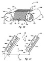
- FIG. 1B is an enlarged perspective view of a heat exchanger having canted heat exchange elements configured in accordance with an embodiment of the invention.
- FIG. 1C is an enlarged, cross-sectional side view of two heat exchange elements from the heat exchanger of FIG. 1B , configured in accordance with an embodiment of the invention.
- FIG. 2 is a cross-sectional side view of a heat exchange element having non-identical internal channels configured in accordance with another embodiment of the invention.
- FIG. 3 is a front view of a heat exchange element having a plurality of fin configurations positioned along an air flow path in accordance with another embodiment of the invention.
- FIG. 4 is a perspective view of a heat exchanger having partitioned inlet and/or outlet manifolds configured in accordance with another embodiment of the invention and suitable for use in the computer system of FIG. 1A .
- FIG. 5 is a top view of a heat exchanger having counter-flowing working fluids configured in accordance with a further embodiment of the invention and suitable for use in the computer system of FIG. 1A .
- FIG. 1A is a partially schematic elevation view of a computer system 100 having a plurality of internal heat exchangers 118 (identified individually as heat exchangers 118 a - d ) configured in accordance with an embodiment of the invention.
- the computer system 100 can include a computer cabinet 102 in a room 101 .
- Working fluid lines 106 (identified individually as a supply line 106 a and a return line 106 b ) connect the computer cabinet 102 to a heat removal system 104 .
- the heat removal system 104 is situated in the room 101 and spaced apart from the computer cabinet 102 . In other embodiments, however, the heat removal system 104 can be integrated into the computer cabinet 102 , positioned outside the room 101 , or situated in other suitable places.
- the computer cabinet 102 can include an air inlet 114 for receiving cooling air from the room 101 or a floor plenum (not shown), an air outlet 116 for discharging air to the room 101 , and a plurality of computer module compartments 120 (identified individually as first, second, and third computer module compartments 120 a - c , respectively) arranged vertically between the air inlet 114 and the air outlet 116 in a chassis 110 .
- Individual computer module compartments 120 hold a plurality of computer modules 112 oriented edgewise with respect to the flow of cooling air through the chassis 110 .
- the computer cabinet 102 can also hold a plurality of heat exchangers 118 in the chassis 110 .
- the individual heat exchangers 118 can be configured to receive a working fluid (not shown) from the heat removal system 104 via the supply line 106 a . After flowing through the heat exchangers 118 , the working fluid returns to the heat removal system 104 via the return line 106 b .
- the working fluid can include hydrofluorocarbons, hydrochlorofluorocarbons, chlorofluorocarbons, ammonia, and/or other suitable refrigerants known in the art.
- the working fluid can include a vapor phase fluid, a liquid phase fluid, or a two-phase fluid when flowing through the heat exchangers 118 .
- the computer cabinet 102 can additionally include an air mover 130 (e.g., a fan) positioned proximate to the air inlet 114 to facilitate movement of the cooling air through the chassis 110 along a flow path 117 .
- the air mover 130 can draw air from the room 101 or a floor plenum into the chassis 110 through the air inlet 114 . The air then flows through the chassis 110 past the computer modules 112 , and exits the chassis 110 via the air outlet 116 .
- the heat removal system 104 can include a pump 124 in fluid communication with a condenser 122 .
- the condenser 122 can be a shell-and-tube type heat exchanger, a plate-and-frame type heat exchanger, or other suitable type of heat exchanger known in the art.
- the condenser 122 can include a working fluid inlet 126 a for receiving heated working fluid returning from the computer cabinet 102 , and a working fluid outlet 126 b for supplying cooled working fluid to the pump 124 .
- the condenser 122 can also include a coolant inlet 128 a and a coolant outlet 128 b for circulating chilled water, cooling water, or other suitable coolant (not shown) to cool the working fluid.
- the pump 124 can include a positive displacement pump, a centrifugal pump, or other suitable type of pump for circulating the working fluid back to the heat exchangers 118 via the supply line 106 a.
- the air mover 130 draws air into the chassis 110 through the air inlet 114 .
- the first heat exchanger 118 a cools the air before it flows into the first compartment 120 a .
- the computer modules 112 in the first compartment 120 a transfer heat to the air.
- the second heat exchanger 118 b then cools the air before the air passes into the second compartment 120 b by absorbing heat from the air into the working fluid.
- the air is similarly cooled by the third heat exchanger 118 c before flowing into the third compartment 120 c .
- the fourth heat exchanger 118 d then cools the heated air leaving the third compartment 120 c before the air is discharged to the room 101 via the air outlet 116 .
- the working fluid is in phase transition between liquid and vapor as the working fluid leaves the heat exchangers 118 .
- the working fluid can have other phase conditions at this time.
- the heated working fluid from the heat exchangers 118 returns to the condenser 122 via the return line 106 b .
- the coolant in the condenser 122 cools the working fluid before the pump 124 circulates the working fluid back to the heat exchangers 118 .
- FIG. 1A Only a single computer cabinet 102 is shown in FIG. 1A for purposes of illustration and ease of reference. In other embodiments, however, supercomputers and other large computer systems can include a plurality of computer cabinets arranged in banks or other configurations. In such embodiments, the heat removal system 104 can provide working fluid to one or more of the computer cabinets 102 via an appropriately configured piping circuit. Further, although the heat exchangers 118 have been described above in the context of working fluid-type heat exchangers, in other embodiments, other types of heat exchangers can be used to inter-cool the air moving through the compartments 120 without departing from the spirit or scope of the present invention.
- FIG. 1B is an enlarged perspective view of one of the heat exchangers 118 configured in accordance with an embodiment of the invention.
- the heat exchanger 118 can include a plurality of heat exchange elements 132 extending between and in fluid communication with an inlet manifold 134 and an outlet manifold 135 . Although four heat exchange elements 132 are shown in FIG. 1B , in other embodiments, the heat exchanger 118 can include more or fewer heat exchange elements 132 depending on a number of factors including heat load, cost, manufacturability, etc.
- the inlet manifold 134 can include a distribution section 137 c extending between an inlet port 137 a and a capped inlet end 137 b .
- the distribution section 137 c includes a generally tubular structure (e.g., a section of a pipe or a tube) with a plurality of first slots 137 d arranged along a length of the distribution section 137 c .
- the first slots 137 d are configured to receive first end portions of the heat exchange elements 132 .
- the distribution section 137 c can have other configurations to accommodate other factors.
- the outlet manifold 135 is generally similar to the inlet manifold 134 .
- the outlet manifold 135 includes a collection section 139 c extending between an outlet port 139 a and a capped outlet end 139 b .
- the collection section 139 c includes a generally tubular structure with a plurality of second slots 139 d arranged along a length of the collection section 139 c in one-to-one correspondence with the first slots 137 d .
- the outlet manifold 135 can have other configurations, including others that differ from the inlet manifold 134 .
- the collection section 139 c can have a different cross-sectional shape and/or a different size than the distribution section 137 c.
- the individual heat exchange elements 132 can include a plurality of fins 142 extending from a passage portion 140 .
- a first end portion 132 a of the passage portion 140 is coupled to the inlet manifold 134 via the first slots 137 d
- a second end portion 132 b of the passage portion 140 is coupled to the outlet manifold 135 via the second slots 139 d .
- the passage portion 140 extends into both the inlet manifold 134 and the outlet manifold 135 . In other embodiments, however, the ends of the passage portion 140 can be generally flush with the first and/or second slots 137 d , 139 d . Further details of several embodiments of the passage portion 140 are described below with reference to FIG. 1C .
- FIG. 1C is an enlarged side view of two of the heat exchange elements 132 of FIG. 1B , configured in accordance with one embodiment of the invention.
- the heat exchange elements 132 can be at least generally parallel to each other with a gap D (e.g., from about 1 cm to about 2 cm, or any other desired spacing) therebetween. In other embodiments, however, at least some of the heat exchange elements 132 can be nonparallel to the other heat exchange elements 132 .
- the gap D can form an air passage 136 in fluid communication with the air flow path 117 .
- the air passage 136 allows cooling air to flow past the heat exchange elements 132 during operation of the computer system 100 .
- individual heat exchange elements 132 can be canted relative to the incoming air flow path 117 a .
- the heat exchange elements 132 can form an angle A of from about 10° to about 45°, preferably from about 15° to about 40°, and more preferably about 20° to about 30° relative to the air flow path 117 a .
- the heat exchange elements 132 and the air flow path 117 a can form other suitable angles.
- Each of the heat exchange elements 132 can form the same angle or different angles relative to the air flow path 117 .
- the angles can increase or decrease (e.g., linearly, exponentially, etc.) from one heat exchange element 132 to another.
- the individual heat exchange elements 132 can include a plurality of internal fluid channels 144 (identified individually as first, second, third, and fourth internal channels 144 a - d , respectively).
- the internal channels 144 have generally the same cross-sectional shape, e.g., a generally rectangular shape, and generally the same cross-sectional area. In other embodiments, however, the internal channels 144 can have other cross-sectional shapes, such as triangular shapes, circular shapes, oval shapes, and/or other suitable shapes and/or cross-sectional areas.
- the internal channels 144 can have non-identical configurations, as described in more detail below with reference to FIG. 2 .
- a working fluid flows into the inlet manifold 134 via the inlet port 137 a , as indicated by the arrow 131 a .
- the inlet manifold 134 distributes the working fluid to the internal channels 144 at the first end 132 a of each of the heat exchange elements 132 .
- the working fluid flows across the heat exchange elements 132 from the first end 132 a toward the second end 132 b .
- the working fluid absorbs heat from cooling air flowing through the air passage 136 and/or past the fins 142 .
- the working fluid can be at least partially vaporized (i.e., a two-phase fluid) at the outlet manifold 135 .
- the working fluid can be sub-cooled at the outlet manifold 135 .
- the working fluid can be substantially completely vaporized at the outlet manifold 135 .
- the collection section 139 c of the outlet manifold 135 collects the heated working fluid and returns the heated working fluid to the heat removal system 104 ( FIG. 1A ) via the outlet port 139 a , as indicated by the arrow 131 b.
- Canting the heat exchange elements 132 can improve heat distribution along a length L ( FIG. 1C ) of the heat exchange elements 132 .
- the working fluid in one of the internal channels 144 e.g., the fourth internal channel 144 d
- the working fluid in one of the internal channels 144 can absorb heat from air streams that have not been significantly cooled by working fluid flowing through other internal channels 144 (e.g., the first, second, and/or third internal channels 144 a - c ).
- heat distribution along the length L of the heat exchange element 132 can be more efficient than with heat exchange elements arranged parallel to the air flow.
- the canted heat exchange elements 132 can also increase the heat transfer area without significantly affecting the height of the heat exchanger 118 .
- the canted heat exchange elements 132 can improve energy distribution in the computer cabinet 102 ( FIG. 1A ) because the canted heat exchange elements 132 can deflect cooling air to other parts of the computer cabinet 102 during operation, as indicated by the arrow 117 .
- FIG. 2 is a cross-sectional side view of a heat exchange element 232 having non-identical internal channels configured in accordance with another embodiment of the invention.
- the heat exchange element 232 can include a plurality of internal channels 244 (identified individually as first, second, third, and fourth internal channel 244 a - d , respectively), and at least one internal channel 244 has a different internal configuration than others.
- the cross-sectional area of the internal channels 244 can sequentially decrease from the first internal channel 244 a to the fourth internal channel 244 d .
- first and second internal channels 244 a - b can have a first cross-sectional area
- third and fourth internal channels 244 c - d can have a second cross-sectional area, smaller than the first cross-sectional area.
- the internal channels 244 can have different cross-sectional shapes and/or other arrangements.
- the different internal configurations of the internal channels 244 can allow the working fluid to have different mass flow rates when flowing through the internal channels 244 .
- the first internal channel 244 a has a larger cross-sectional area than that of the second internal channel 244 b .
- the mass flow rate of working fluid through the first internal channel 244 a will be greater than the mass flow rate of the working fluid through the second internal channel 244 b for a given fluid pressure.
- Controlling the flow rate of the working fluid flowing through individual internal channels 244 can improve heat transfer performance of the heat exchange element 232 .
- the inventor has recognized that, in certain situations, the working fluid flowing through the first internal channel 244 a can be completely vaporized before and/or when it reaches the outlet manifold 135 ( FIG. 1B ).
- the completely vaporized working fluid typically cannot efficiently transfer heat because of a low heat capacity.
- the working fluid can be at least a two-phase fluid when it reaches the outlet manifold 135 , thus improving the heat transfer efficiency.
- the heat exchange element 232 can include other features that affect the mass flow rate of the working fluid in the internal channels 244 .
- individual internal channels 244 can include an orifice, a nozzle, and/or other flow restricting components.
- the heat exchange element 232 can include a barrier (not shown) that partially blocks the cross-section of at least one of the internal channels 244 .
- FIG. 3 is a front view of a heat exchange element 332 having a fin configuration configured in accordance with a further embodiment of the invention.
- the heat exchange element 332 includes a first fin portion 342 a and a second fin portion 342 b arranged along the air flow path 117 .
- the first fin portion 342 a can include a plurality of first fins 343 a
- the second fin portion 342 b can include a plurality of second fins 343 b , different than the first fins 343 a .
- the second fin portion 342 b can have a larger number of fins 343 b than the first fin portion 342 a .
- the second fin portion 342 b can include different types of fins than the first fin portion 342 a (e.g., the second fins 343 b can have different heights, thicknesses, etc). In a further embodiment, the second fins 343 b can have a higher heat conductance than the first fins 343 a . In any of these embodiments, the second fin portion 342 b can have a higher heat transfer coefficient that the first fin portion 342 a.
- the inventor has recognized that if the fins have the same configuration along the length L of the heat exchange element 332 , the working fluid flowing through the fourth internal channel 144 d ( FIG. 1C ) is likely to be mostly liquid when it reaches the outlet manifold 135 ( FIG. 1B ). Thus, the heat transfer between the working fluid and the cooling air is limited because the mostly liquid working fluid typically has a latent heat capacity much lower than its heat of vaporization.
- the inventor has further recognized that the limiting factor in the heat transfer between the working fluid and the cooling air is the heat transfer rate between the fins and the cooling air. Thus, by increasing the heat transfer efficiency and/or capability of the second fin portion 342 b , the heat transfer between the working fluid in the fourth internal channel 144 d and the cooling air can be improved.
- FIG. 4 is a partially exploded perspective view of a heat exchanger 418 configured in accordance with another embodiment of the invention and suitable for use in the computer system 100 of FIG. 1A .
- the heat exchanger 418 can include a plurality of heat exchange elements 432 extending between an inlet manifold 434 and an outlet manifold 435 .
- the individual heat exchange elements 432 can include a plurality of fins 442 extending from a passage portion 440 .
- the passage portion 440 can be generally similar to the passage portion 140 of FIGS. 1B and 1C , or the passage portion 240 of FIG. 2 .
- the inlet manifold 434 can include a distribution section 437 c extending between an inlet opening 437 a and a capped inlet end 437 b .
- the inlet manifold 434 can also include an inlet divider 448 extending between the inlet opening 437 a and the inlet end 437 b .
- the inlet divider 448 separates the distribution section 437 c into a first inlet volume 450 a and a second inlet volume 450 b .
- the inlet divider 448 also separates the inlet opening 437 a into a first inlet port 452 a and a second inlet port 452 b.
- the outlet manifold 435 is generally similar to the inlet manifold 434 .
- the outlet manifold 435 includes a collection section 439 c extending between an outlet opening 439 a and a capped outlet end 439 b .
- the outlet manifold 435 can also include an outlet divider 458 that separates the collection section 439 c into a first outlet volume 460 a and a second outlet volume 460 b .
- the outlet divider 458 also separates the outlet opening 439 a into a first outlet port 462 a and a second outlet port 462 b.
- the inlet and outlet dividers 448 , 458 cooperate to separate the internal channels 144 ( FIG. 1C ) of individual heat exchange elements 432 into a first channel portion 444 a corresponding to the first inlet/outlet volumes 450 a , 460 a and a second channel portion 444 b corresponding to the second inlet/outlet volumes 450 b , 460 b .
- the first inlet volume 450 a , the first channel portion 444 a , and the first outlet volume 460 a form a first flow path of the heat exchanger 418 .
- the second inlet volume 450 b , the second channel portion 444 b , and the second outlet volume 460 b form a second flow path of the heat exchanger 418 .
- the first and second flow paths are isolated from each other and arranged along the air flow path 117 .
- the heat exchanger 418 can receive a first working fluid portion via the first inlet port 452 a , as indicated by arrow 470 a , and a second working fluid portion via the second inlet port 452 b , as indicated by arrow 472 a .
- the first and second inlet volumes 450 a - b distribute the first and second working fluid portions to the first and second channel portions 444 a - b , respectively.
- the first and second working fluid portions flow across the heat exchange elements 432 , as indicated by arrows 470 b and 472 b , respectively. As the first and second working fluid portions flow across the heat exchange elements 432 , they absorb heat from the cooling air flowing past the fins 442 .
- the first and second outlet volumes 460 a - b collect the heated first and second working fluid portions and returns them to the heat removal system 104 ( FIG. 1A ) via the first and second outlet ports 462 a and 462 b , respectively, as indicated by arrows 470 c and 472 c , respectively.
- the first and second working fluid portions can have different physical characteristics.
- the first working fluid portion can have a mass flow rate that is less than the second working fluid portion.
- the first working fluid portion can have a higher heat transfer coefficient than the second working fluid portion.
- the first working fluid portion can have a lower boiling point than the second working fluid portion.
- the first working fluid portion can have a higher heat of vaporization than the second working fluid portion.
- the heat exchanger 418 can have improved heat transfer performance compared to conventional heat exchangers.
- the inventor has recognized that if the same working fluid is flowing through all the internal channels of the heat exchange elements 432 , the working fluid in those channels proximate to the incoming cooling air is likely to be completely vaporized, while the working fluid in other channels spaced apart from the incoming cooling air may still be in liquid phase.
- an operator can improve the heat transfer between the working fluid and the cooling air.
- the inlet divider 448 and the outlet divider 458 are illustrated in FIG. 4 as being generally perpendicular to the air flow path 117 , in other embodiments, at least one of the inlet divider 448 and the outlet divider 458 can be canted relative to the air flow path 117 . In further embodiments, at least one of the inlet divider 448 and the outlet divider 458 can be omitted, and/or at least one of the first and second inlet/outlet volumes 450 a - b , 460 a - b can be standalone structures.
- the first and second inlet volumes 450 a - b can each include a generally tubular structure and spaced apart from each other.
- FIG. 5 is a top view of a heat exchanger 518 configured in accordance with a further embodiment of the invention and suitable for use in the computer system 100 of FIG. 1A .
- the heat exchanger 518 can include a plurality of heat exchange elements 532 (identified individually as first, second, third, and fourth heat exchange elements 532 a - d , respectively) extending between a first manifold 534 and a second manifold 535 .
- the individual heat exchange elements 532 can include a passage portion 540 and have a plurality of fins 542 extending from the passage portion 540 .
- the passage portion 540 can be generally similar to the passage portion 140 of FIGS. 1B and 1C , or FIG. 2 .
- the first manifold 534 can include a first intermediate section 537 c extending between a first opening 537 a and a capped first end 537 b .
- the first manifold 534 can also include a first divider 548 extending between the first opening 537 a and the first end 537 b .
- the first divider 548 separates the first intermediate section 537 c into a first distribution volume 550 a and a first collection volume 550 b .
- the first divider 548 also separates the first opening 537 a into a first inlet port 552 a and a first outlet port 552 b.
- the first distribution volume 550 a and the first collection volume 550 b are in fluid communication with only a portion of the heat exchange elements 532 .
- the first distribution volume 550 a is in fluid communication with the second and fourth heat exchange elements 532 b , 532 d
- the first collection volume 550 b is in fluid communication with the first and third heat exchange elements 532 a , 532 c .
- the first manifold 534 can also have other flow configurations.
- the second manifold 535 can include a second intermediate section 539 c extending between a second opening 539 a and a capped second end 539 b .
- the second manifold 535 can also include a second divider 558 extending between the second opening 539 a and the second end 539 b .
- the second divider 558 separates the second intermediate section 539 c into a second distribution volume 560 a and a second collection volume 560 b .
- the second divider 558 also separates the second opening 539 a into a second inlet port 562 a and a second outlet port 562 b.
- the second distribution volume 560 a and the second collection volume 560 b are in fluid communication with only a portion of the heat exchange elements 532 .
- the second distribution volume 560 a is in fluid communication with the first and third heat exchange elements 532 a , 532 c
- the second collection volume 560 b is in fluid communication with the second and fourth heat exchange elements 532 b , 532 d .
- the second manifold 535 can also have other flow configurations.
- the heat exchanger 518 can thus have a first flow path from the first inlet port 552 a to the second outlet port 562 b via the first distribution volume 550 a , the second and fourth heat exchange elements 532 b , 532 d , and the second collection volume 560 b .
- the heat exchanger 518 can also have a second flow path from the second inlet port 562 a to the first outlet port 552 b via the second distribution volume 560 a , the first and third heat exchange elements 532 a , 532 c , and the first collection volume 550 b.
- the heat exchanger 518 can receive a first working fluid portion via the first inlet port 552 a , as indicated by arrow 570 a , and a second working fluid portion via the second inlet port 562 a , as indicated by arrow 572 a .
- the first and second distribution volumes 550 a , 560 a distribute the first and second working fluid portions to corresponding heat exchange elements 532 .
- the first working fluid portion then flows across the second and fourth heat exchange elements 532 b , 532 d in a first direction, as indicated by arrow 570 b .
- the second working fluid portion then flows across the first and third heat exchange elements 532 a , 532 c in a second direction, as indicated by arrow 572 b .
- the second direction is generally opposite the first direction.
- the first and second directions can form an angle of about 120° to about 180°.
- the first and second collection volumes 550 b , 560 b collect the heated first and second working fluid portions and return them to the heat removal system 104 ( FIG. 1A ) via the first and second outlet ports 552 b , 562 b , as indicated by arrows 570 c , 572 c , respectively.
- the heat exchanger 518 can have improved heat transfer efficiency compared to conventional heat exchangers.
- the inventor has recognized that the heat transfer efficiency decreases as the first and/or second portions of working fluid flow across the heat exchange elements. Thus, if the first and second working fluid portions flow in the same direction, one side of the heat exchanger 518 may have insufficient heat transfer.
- the heat transfer efficiency between the first and second working fluid portions and the cooling air can be improved.
- the heat exchangers shown in FIGS. 4 and 5 can also incorporate the heat exchange elements shown in FIGS. 2 and 3 .
- the heat exchanger shown in FIG. 1B can also incorporate the inlet/outlet manifolds of FIG. 4 or FIG. 5 .
- advantages associated with certain embodiments of the invention have been described in the context of those embodiments, other embodiments may also exhibit such advantages, and not all embodiments need necessarily exhibit such advantages to fall within the scope of the invention. Accordingly, the invention is not limited, except as by the appended claims.
Abstract
Description
Claims (8)
Priority Applications (4)
| Application Number | Priority Date | Filing Date | Title |
|---|---|---|---|
| US12/862,002 US8820395B2 (en) | 2007-12-17 | 2010-08-24 | Cooling systems and heat exchangers for cooling computer components |
| US14/283,299 US9288935B2 (en) | 2007-12-17 | 2014-05-21 | Cooling systems and heat exchangers for cooling computer components |
| US14/444,985 US9596789B2 (en) | 2007-12-17 | 2014-07-28 | Cooling systems and heat exchangers for cooling computer components |
| US15/420,863 US10082845B2 (en) | 2007-12-17 | 2017-01-31 | Cooling systems and heat exchangers for cooling computer components |
Applications Claiming Priority (2)
| Application Number | Priority Date | Filing Date | Title |
|---|---|---|---|
| US11/958,114 US20090154091A1 (en) | 2007-12-17 | 2007-12-17 | Cooling systems and heat exchangers for cooling computer components |
| US12/862,002 US8820395B2 (en) | 2007-12-17 | 2010-08-24 | Cooling systems and heat exchangers for cooling computer components |
Related Parent Applications (1)
| Application Number | Title | Priority Date | Filing Date |
|---|---|---|---|
| US11/958,114 Division US20090154091A1 (en) | 2007-12-17 | 2007-12-17 | Cooling systems and heat exchangers for cooling computer components |
Related Child Applications (2)
| Application Number | Title | Priority Date | Filing Date |
|---|---|---|---|
| US14/283,299 Division US9288935B2 (en) | 2007-12-17 | 2014-05-21 | Cooling systems and heat exchangers for cooling computer components |
| US14/444,985 Division US9596789B2 (en) | 2007-12-17 | 2014-07-28 | Cooling systems and heat exchangers for cooling computer components |
Publications (2)
| Publication Number | Publication Date |
|---|---|
| US20100317279A1 US20100317279A1 (en) | 2010-12-16 |
| US8820395B2 true US8820395B2 (en) | 2014-09-02 |
Family
ID=40752923
Family Applications (5)
| Application Number | Title | Priority Date | Filing Date |
|---|---|---|---|
| US11/958,114 Abandoned US20090154091A1 (en) | 2007-12-17 | 2007-12-17 | Cooling systems and heat exchangers for cooling computer components |
| US12/862,002 Active 2028-07-17 US8820395B2 (en) | 2007-12-17 | 2010-08-24 | Cooling systems and heat exchangers for cooling computer components |
| US14/283,299 Active 2028-06-03 US9288935B2 (en) | 2007-12-17 | 2014-05-21 | Cooling systems and heat exchangers for cooling computer components |
| US14/444,985 Active 2028-09-26 US9596789B2 (en) | 2007-12-17 | 2014-07-28 | Cooling systems and heat exchangers for cooling computer components |
| US15/420,863 Active 2028-02-08 US10082845B2 (en) | 2007-12-17 | 2017-01-31 | Cooling systems and heat exchangers for cooling computer components |
Family Applications Before (1)
| Application Number | Title | Priority Date | Filing Date |
|---|---|---|---|
| US11/958,114 Abandoned US20090154091A1 (en) | 2007-12-17 | 2007-12-17 | Cooling systems and heat exchangers for cooling computer components |
Family Applications After (3)
| Application Number | Title | Priority Date | Filing Date |
|---|---|---|---|
| US14/283,299 Active 2028-06-03 US9288935B2 (en) | 2007-12-17 | 2014-05-21 | Cooling systems and heat exchangers for cooling computer components |
| US14/444,985 Active 2028-09-26 US9596789B2 (en) | 2007-12-17 | 2014-07-28 | Cooling systems and heat exchangers for cooling computer components |
| US15/420,863 Active 2028-02-08 US10082845B2 (en) | 2007-12-17 | 2017-01-31 | Cooling systems and heat exchangers for cooling computer components |
Country Status (1)
| Country | Link |
|---|---|
| US (5) | US20090154091A1 (en) |
Cited By (19)
| Publication number | Priority date | Publication date | Assignee | Title |
|---|---|---|---|---|
| US20120309284A1 (en) * | 2009-12-22 | 2012-12-06 | Atrium Data | Method and device for reducing the energy consumption of a center comprising energy-intensive apparatuses |
| US20130295834A1 (en) * | 2012-05-07 | 2013-11-07 | Microsoft Corporation | Multi-chassis climate regulator plenum |
| US20140049146A1 (en) * | 2011-09-23 | 2014-02-20 | Cloud Dynamics Inc. | Data center equipment cabinet system |
| US20140326436A1 (en) * | 2011-09-19 | 2014-11-06 | Amazon Technologies, Inc. | Carrier with adjustable heat removal elements |
| US20150144309A1 (en) * | 2013-03-13 | 2015-05-28 | Brayton Energy, Llc | Flattened Envelope Heat Exchanger |
| WO2016069354A1 (en) * | 2014-10-27 | 2016-05-06 | Ebullient, Llc | Heat exchanger with helical passageways |
| US20170003039A1 (en) * | 2015-07-02 | 2017-01-05 | Schneider Electric It Corporation | Cooling system and method having micro-channel coil with countercurrent circuit |
| US9638480B1 (en) | 2016-02-05 | 2017-05-02 | Ford Global Technologies, Llc | System and method for cooling vehicle computing device |
| US9848509B2 (en) | 2011-06-27 | 2017-12-19 | Ebullient, Inc. | Heat sink module |
| US9852963B2 (en) | 2014-10-27 | 2017-12-26 | Ebullient, Inc. | Microprocessor assembly adapted for fluid cooling |
| US9885526B2 (en) | 2016-03-11 | 2018-02-06 | Ford Global Technologies, Llc | Cooling system for vehicle sensor modules |
| US9891002B2 (en) | 2014-10-27 | 2018-02-13 | Ebullient, Llc | Heat exchanger with interconnected fluid transfer members |
| US20180132386A1 (en) * | 2016-11-09 | 2018-05-10 | Inventec (Pudong) Technology Corporation | Radiator and server cooling system including the same |
| US10082845B2 (en) | 2007-12-17 | 2018-09-25 | Cray, Inc. | Cooling systems and heat exchangers for cooling computer components |
| US20190335618A1 (en) * | 2018-04-27 | 2019-10-31 | Hewlett Packard Enterprise Development Lp | Cooling fluids in opposite directions across a device |
| US10588246B2 (en) | 2008-02-11 | 2020-03-10 | Cray, Inc. | Systems and associated methods for controllably cooling computer components |
| US11371694B2 (en) | 2016-12-22 | 2022-06-28 | Trinity Endeavors, Llc | Fire tube |
| US11703282B2 (en) | 2016-12-22 | 2023-07-18 | Trinity Endeavors, Llc | Fire tube |
| US11906218B2 (en) | 2014-10-27 | 2024-02-20 | Ebullient, Inc. | Redundant heat sink module |
Families Citing this family (21)
| Publication number | Priority date | Publication date | Assignee | Title |
|---|---|---|---|---|
| US20090116186A1 (en) * | 2006-07-04 | 2009-05-07 | Fujitsu Limited | Cooling unit and electronic apparatus |
| US8081459B2 (en) | 2008-10-17 | 2011-12-20 | Cray Inc. | Air conditioning systems for computer systems and associated methods |
| US8472181B2 (en) | 2010-04-20 | 2013-06-25 | Cray Inc. | Computer cabinets having progressive air velocity cooling systems and associated methods of manufacture and use |
| MX2013007123A (en) | 2010-12-22 | 2013-08-01 | Cooper Technologies Co | Manifold for controlling airflow within an explosion-proof enclosure. |
| CA2819897C (en) | 2010-12-22 | 2019-02-19 | Cooper Technologies Company | Controlling airflow within an explosion-proof enclosure |
| US9232683B2 (en) * | 2011-07-22 | 2016-01-05 | Seagate Technology Llc | Storage system and a method of cooling storage media within a data storage system |
| DE102011089091A1 (en) * | 2011-12-19 | 2013-06-20 | Behr Gmbh & Co. Kg | Heat exchanger |
| US9801310B2 (en) * | 2013-04-03 | 2017-10-24 | International Business Machines Corporation | Server cooling system without the use of vapor compression refrigeration |
| JP6136670B2 (en) * | 2013-07-08 | 2017-05-31 | 富士通株式会社 | Information processing apparatus, exhaust unit, and data center |
| JP6531380B2 (en) * | 2014-12-12 | 2019-06-19 | ダイキン工業株式会社 | Heat exchanger |
| WO2016152111A1 (en) * | 2015-03-23 | 2016-09-29 | 日本電気株式会社 | Phase change cooling device and phase change cooling method |
| KR102478547B1 (en) | 2016-08-26 | 2022-12-16 | 이너테크 아이피 엘엘씨 | Cooling system and method using a flat tube heat exchanger with single-phase fluid and counterflow circuits |
| CN108930423B (en) * | 2017-05-26 | 2020-09-08 | 华为技术有限公司 | Data center |
| CN107787164B (en) * | 2017-09-26 | 2019-08-27 | 青岛海信电器股份有限公司 | A kind of liquid cooling block, liquid cooling heat radiation system and laser projection |
| CN107911966A (en) * | 2017-11-09 | 2018-04-13 | 乐山师范学院 | A kind of safety means of computer network |
| US20190212066A1 (en) * | 2018-01-11 | 2019-07-11 | Asia Vital Components Co., Ltd. | Water-cooling radiator assembly with internal horiziontal partition members and flow disturbing members |
| CN111173326B (en) * | 2020-01-12 | 2021-07-16 | 苏州浪潮智能科技有限公司 | Multistage refrigerated data center computer lab |
| CN113900054B (en) * | 2020-07-06 | 2024-01-30 | 西门子(深圳)磁共振有限公司 | Cabinet and magnetic resonance imaging system |
| US11737246B2 (en) * | 2021-04-27 | 2023-08-22 | Quanta Computer Inc. | Dual-radiator cooling device |
| US20230200017A1 (en) * | 2021-12-20 | 2023-06-22 | Microsoft Technology Licensing, Llc | Systems and methods for electromagnetic shielding of thermal fin packs |
| WO2023215845A1 (en) * | 2022-05-04 | 2023-11-09 | Hoffman Enclosures Inc. | System and method for sidecar cooling system |
Citations (279)
| Publication number | Priority date | Publication date | Assignee | Title |
|---|---|---|---|---|
| US2628018A (en) | 1950-04-13 | 1953-02-10 | Westinghouse Electric Corp | Air translating apparatus |
| US2673721A (en) | 1951-04-13 | 1954-03-30 | Bell Telephone Labor Inc | Apparatus for cooling electron discharge devices |
| US2861782A (en) | 1957-01-18 | 1958-11-25 | Swartz Elmer | Holder for electron tubes |
| US3120166A (en) | 1961-11-16 | 1964-02-04 | Kooltronic Fan Company | Cooling duct for cabinets |
| US3192306A (en) | 1962-09-26 | 1965-06-29 | Philco Corp | Cooling wall structure for electronic equipment cabinet |
| US3236296A (en) | 1961-06-21 | 1966-02-22 | Lambda Electronics Corp | Heat exchanger |
| US3317798A (en) | 1966-04-13 | 1967-05-02 | Ibm | Cooling electrical apparatus |
| US3348609A (en) | 1966-04-29 | 1967-10-24 | Lambda Electronics Corp | Multi-positional power supply module and heat exchange techniques |
| US3525385A (en) | 1968-10-07 | 1970-08-25 | Ralph C Liebert | Computer refrigeration system |
| US3559728A (en) | 1968-11-29 | 1971-02-02 | Kooltronic Fan Co | Electronic equipment rack temperature control |
| US3648754A (en) | 1969-07-28 | 1972-03-14 | Hugo H Sephton | Vortex flow process and apparatus for enhancing interfacial surface and heat and mass transfer |
| US3903404A (en) | 1973-10-17 | 1975-09-02 | Amdahl Corp | Computer construction and method |
| US3942426A (en) | 1975-04-14 | 1976-03-09 | Restaurant Technology, Inc. | Heated sanitary sandwich bin with air curtains |
| US4016357A (en) | 1975-07-18 | 1977-04-05 | Burroughs Corporation | Floor structure for the environment of a modular computer system |
| US4158875A (en) | 1977-05-24 | 1979-06-19 | Nippon Electric Co., Ltd. | Air cooling equipment for electronic systems |
| US4261519A (en) | 1978-12-20 | 1981-04-14 | Honeywell Information Systems Inc. | Air distribution system |
| US4270362A (en) | 1977-04-29 | 1981-06-02 | Liebert Corporation | Control system for an air conditioning system having supplementary, ambient derived cooling |
| US4271678A (en) | 1977-03-21 | 1981-06-09 | Liebert Corporation | Liquid refrigeration system for an enclosure temperature controlled outdoor cooling or pre-conditioning |
| US4306613A (en) | 1980-03-10 | 1981-12-22 | Christopher Nicholas S | Passive cooling system |
| US4313310A (en) | 1979-09-07 | 1982-02-02 | Fujitsu Limited | Cooling system |
| US4315300A (en) | 1979-01-29 | 1982-02-09 | The United States Of America As Represented By The Secretary Of The Navy | Cooling arrangement for plug-in module assembly |
| US4386651A (en) | 1980-12-02 | 1983-06-07 | Autz + Herrmann Metallwaren-Und Maschinenfabrik | Heat exchanger accessory for electronic circuit cabinets |
| US4449579A (en) | 1981-01-30 | 1984-05-22 | Tokyo Shibaura Denki Kabushiki Kaisha | Cooling apparatus for a closed housing |
| US4458296A (en) | 1982-05-19 | 1984-07-03 | The Boeing Company | Avionic shelf assembly |
| US4473382A (en) | 1983-07-08 | 1984-09-25 | Lasko Metal Products, Inc. | Air cleaning and circulating apparatus |
| US4513351A (en) | 1982-09-29 | 1985-04-23 | International Business Machines Corporation | Electronic assembly with forced convection cooling |
| US4528614A (en) | 1983-10-07 | 1985-07-09 | Westinghouse Electric Corp. | Electric control center having integral air-ventilation system |
| US4535386A (en) | 1983-05-23 | 1985-08-13 | Allen-Bradley Company | Natural convection cooling system for electronic components |
| US4600050A (en) | 1985-04-26 | 1986-07-15 | Noren Don W | Heat exchanger |
| US4642715A (en) | 1984-11-01 | 1987-02-10 | Miltope Corporation | Environmental conditioning and safety system for disk-type mass memories |
| US4644443A (en) | 1985-09-27 | 1987-02-17 | Texas Instruments Incorporated | Computer cooling system using recycled coolant |
| US4691274A (en) | 1986-04-29 | 1987-09-01 | Modular Power Corporation | Modular electronic power supply |
| US4702154A (en) | 1987-01-28 | 1987-10-27 | Dodson Douglas A | Cooling system for personal computer |
| US4728160A (en) | 1986-10-22 | 1988-03-01 | Digital Equipment Corporation | Cabinet for a computer assembly |
| US4767262A (en) | 1987-04-16 | 1988-08-30 | Knurr-Mechanik Fur Die Elektronik Aktiengesellschaft | Fan slide-in unit |
| US4774631A (en) | 1984-11-15 | 1988-09-27 | Fujitsu Limited | Cooling structure of electronic equipment rack |
| US4797783A (en) | 1984-09-26 | 1989-01-10 | Nec Corporation | Air cooling equipment for electronic systems |
| US4798238A (en) | 1981-05-27 | 1989-01-17 | D.S.D.P. - S.P.A | Shelter for thermally conditioning electronic appliances |
| US4802060A (en) | 1987-03-30 | 1989-01-31 | Rittal-Werk Rudolf Loh Gmbh & Co., Kg | Apparatus for connecting a control panel with an air conditioning device |
| US4860163A (en) | 1988-08-05 | 1989-08-22 | American Telephone And Telegraph Company | Communication equipment cabinet cooling arrangement |
| US4874127A (en) | 1987-11-12 | 1989-10-17 | Collier William R | Climate control apparatus |
| US4901200A (en) | 1987-10-14 | 1990-02-13 | Schroff Gmbh | Insertable housing |
| US4911231A (en) | 1987-10-15 | 1990-03-27 | Bicc Public Limited Company | Electronic enclosure cooling system |
| US4993482A (en) | 1990-01-09 | 1991-02-19 | Microelectronics And Computer Technology Corporation | Coiled spring heat transfer element |
| US5000079A (en) | 1990-05-17 | 1991-03-19 | Mardis Michael C | Noise-attenuating ventilation pedestal for an electronic enclosure |
| US5019880A (en) | 1988-01-07 | 1991-05-28 | Prime Computer, Inc. | Heat sink apparatus |
| US5035628A (en) | 1990-05-29 | 1991-07-30 | Amp Incorporated | Electrical connector for electrically interconnecting two parallel surfaces |
| US5060716A (en) | 1989-03-31 | 1991-10-29 | Heine William F | Heat dissipating device and combination including same |
| US5090476A (en) | 1990-03-20 | 1992-02-25 | Rittal-Werk Rudolf Loh Gmbh & Co. Kg | Air-water heat exchanger for a control box |
| US5101320A (en) | 1991-01-22 | 1992-03-31 | Hayes Microcomputer Products, Inc. | Apparatus for rack mounting multiple circuit boards |
| US5131233A (en) | 1991-03-08 | 1992-07-21 | Cray Computer Corporation | Gas-liquid forced turbulence cooling |
| US5150277A (en) | 1990-05-04 | 1992-09-22 | At&T Bell Laboratories | Cooling of electronic equipment cabinets |
| US5161087A (en) | 1990-10-15 | 1992-11-03 | International Business Machines Corporation | Pivotal heat sink assembly |
| US5165466A (en) | 1991-12-11 | 1992-11-24 | Morteza Arbabian | Modular heat exchanger having delayed heat transfer capability |
| US5168925A (en) * | 1990-11-30 | 1992-12-08 | Aisin Seiki Kabushiki Kaisha | Heat exchanger |
| US5174373A (en) * | 1990-07-13 | 1992-12-29 | Sanden Corporation | Heat exchanger |
| US5196989A (en) | 1990-04-09 | 1993-03-23 | Trw Inc. | Rigid circuit board structure using impingement cooling |
| US5263538A (en) | 1991-10-18 | 1993-11-23 | Aerospatiale Societe Nationale Industrielle | Equipment support, fixing and heat conditioning panel |
| US5273438A (en) | 1992-08-19 | 1993-12-28 | The Whitaker Corporation | Canted coil spring array and method for producing the same |
| US5297990A (en) | 1991-02-01 | 1994-03-29 | Meissner & Wurst Gmbh & Co. | Filter-ventilator-arrangement |
| US5323847A (en) | 1990-08-01 | 1994-06-28 | Hitachi, Ltd. | Electronic apparatus and method of cooling the same |
| US5326317A (en) | 1991-10-18 | 1994-07-05 | Matsushita Seiko Co., Ltd. | Ventilator |
| US5329425A (en) | 1991-02-25 | 1994-07-12 | Alcatel N.V. | Cooling system |
| US5339214A (en) | 1993-02-12 | 1994-08-16 | Intel Corporation | Multiple-fan microprocessor cooling through a finned heat pipe |
| US5345779A (en) | 1993-04-23 | 1994-09-13 | Liebert Corporation | Modular floor sub-structure for the operational support of computer systems |
| US5365402A (en) | 1990-11-30 | 1994-11-15 | Hitachi, Ltd. | Cooling apparatus of electronic device |
| US5376008A (en) | 1993-10-21 | 1994-12-27 | The Whitaker Corporation | Retainer for elastomeric contact element |
| US5395251A (en) | 1993-10-21 | 1995-03-07 | The Whitaker Corporation | Board retainer system for active electrical connector assembly |
| US5402313A (en) | 1993-05-21 | 1995-03-28 | Cummins Engine Company, Inc. | Electronic component heat sink attachment using a canted coil spring |
| US5410448A (en) | 1992-03-02 | 1995-04-25 | Digital Equipment Corporation | Adaptive cooling system |
| US5414591A (en) | 1991-04-15 | 1995-05-09 | Hitachi, Ltd. | Magnetic disk storage system |
| US5467250A (en) | 1994-03-21 | 1995-11-14 | Hubbell Incorporated | Electrical cabinet with door-mounted heat exchanger |
| US5467609A (en) | 1993-04-23 | 1995-11-21 | Liebert Corporation | Modular floor sub-structure for the operational support of computer systems |
| US5471850A (en) | 1993-07-09 | 1995-12-05 | Acurex Corporation | Refrigeration system and method for very large scale integrated circuits |
| US5491310A (en) | 1990-08-16 | 1996-02-13 | Jen; Wang H. | Acoustic board |
| US5493474A (en) | 1995-02-14 | 1996-02-20 | Hewlett-Packard Company | Enclosure with redundant air moving system |
| US5547272A (en) | 1995-04-24 | 1996-08-20 | At&T Global Information Solutions Company | Modular cabinet bezel |
| US5570740A (en) | 1995-03-03 | 1996-11-05 | Dsc Communications Corporation | Built-in cooling system for an enclosure |
| US5572403A (en) | 1995-01-18 | 1996-11-05 | Dell Usa, L.P. | Plenum bypass serial fan cooling subsystem for computer systems |
| US5603375A (en) | 1991-02-01 | 1997-02-18 | Commonwealth Scientific And Industrial Research Organisation | Heat transfer device |
| US5603376A (en) | 1994-08-31 | 1997-02-18 | Fujitsu Network Communications, Inc. | Heat exchanger for electronics cabinet |
| US5684671A (en) | 1995-08-22 | 1997-11-04 | Sequent Computer Systems, Inc. | Packaging architecture for a data server |
| US5685363A (en) | 1994-12-08 | 1997-11-11 | Nissin Electric Co., Ltd. | Substrate holding device and manufacturing method therefor |
| US5707205A (en) | 1996-07-04 | 1998-01-13 | Matsushita Electric Industrial Co., Ltd. | Fan device |
| US5709100A (en) | 1996-08-29 | 1998-01-20 | Liebert Corporation | Air conditioning for communications stations |
| US5718628A (en) | 1995-05-02 | 1998-02-17 | Nit Power And Building Facilities, Inc. | Air conditioning method in machine room having forced air-cooling equipment housed therein |
| US5749702A (en) | 1996-10-15 | 1998-05-12 | Air Handling Engineering Ltd. | Fan for air handling system |
| US5782546A (en) | 1996-04-10 | 1998-07-21 | Nec Corporation | Door structure for cabinets |
| US5793610A (en) | 1996-01-25 | 1998-08-11 | Dell Usa, L.P. | Multi-position air regulation device |
| US5829676A (en) | 1996-11-11 | 1998-11-03 | Kabushiki Kaisha Toyoda Jidoshokki Seisakusho | Heating apparatus and method for vehicle |
| US5849076A (en) | 1996-07-26 | 1998-12-15 | Memc Electronic Materials, Inc. | Cooling system and method for epitaxial barrel reactor |
| US5880931A (en) | 1998-03-20 | 1999-03-09 | Tilton; Donald E. | Spray cooled circuit card cage |
| US5927386A (en) | 1998-08-24 | 1999-07-27 | Macase Industrial Group Ga., Inc. | Computer hard drive heat sink assembly |
| US5941303A (en) * | 1997-11-04 | 1999-08-24 | Thermal Components | Extruded manifold with multiple passages and cross-counterflow heat exchanger incorporating same |
| US5979541A (en) | 1995-11-20 | 1999-11-09 | Seiko Epson Corporation | Cooling fan and cooling fan assembly |
| US6021047A (en) | 1997-10-24 | 2000-02-01 | Dell U.S.A., L,P. | Computer and a rack mount system and method for a computer |
| US6024165A (en) | 1998-08-26 | 2000-02-15 | Dsc Telecom L.P. | Thermal management device and system for an electronic component enclosure |
| US6026565A (en) | 1997-06-12 | 2000-02-22 | Harris Corporation | Housing for diverse cooling configuration printed circuit cards |
| US6034870A (en) | 1999-01-27 | 2000-03-07 | Sun Microsystems, Inc. | Computer system having a highly efficient forced air cooling subsystem |
| US6039414A (en) | 1998-12-11 | 2000-03-21 | Alcatel Usa Sourcing, L.P. | Modular electronic enclosure having rotational molded plastic interlocking components |
| US6046908A (en) | 1998-09-04 | 2000-04-04 | Long Well Electronics Corp. | Heat-radiating structure of power adapter |
| US6052278A (en) | 1998-11-13 | 2000-04-18 | Hewlett-Packard Company | Data storage module and enclosure system |
| US6104608A (en) | 1997-10-30 | 2000-08-15 | Emc Corporation | Noise reduction hood for an electronic system enclosure |
| US6115242A (en) | 1997-10-24 | 2000-09-05 | Advanced Micro Devices, Inc. | Chip chassis including a micro-backplane for receiving and connecting a plurality of computer chips |
| US6132171A (en) | 1997-06-10 | 2000-10-17 | Matsushita Electric Industrial Co., Ltd. | Blower and method for molding housing thereof |
| US6135875A (en) | 1999-06-29 | 2000-10-24 | Emc Corporation | Electrical cabinet |
| US6158502A (en) | 1996-11-18 | 2000-12-12 | Novel Concepts, Inc. | Thin planar heat spreader |
| US6164369A (en) | 1999-07-13 | 2000-12-26 | Lucent Technologies Inc. | Door mounted heat exchanger for outdoor equipment enclosure |
| US6182787B1 (en) | 1999-01-12 | 2001-02-06 | General Electric Company | Rigid sandwich panel acoustic treatment |
| US6185098B1 (en) | 2000-01-31 | 2001-02-06 | Chatsworth Products, Inc. | Co-location server cabinet |
| US6183196B1 (en) | 1998-05-14 | 2001-02-06 | Matsushita Electric Industrial Co., Ltd. | Blower |
| US6208510B1 (en) | 1999-07-23 | 2001-03-27 | Teradyne, Inc. | Integrated test cell cooling system |
| US6205796B1 (en) | 1999-03-29 | 2001-03-27 | International Business Machines Corporation | Sub-dew point cooling of electronic systems |
| US6223812B1 (en) * | 1998-12-07 | 2001-05-01 | Serck Heat Transfer Limited | Heat exchanger core connection |
| US6236564B1 (en) | 2000-04-13 | 2001-05-22 | Enlight Corporation | Detachable fan rack mounting structure |
| US6272012B1 (en) | 2000-02-03 | 2001-08-07 | Crystal Group Inc. | System and method for cooling compact PCI circuit cards in a computer |
| US6305180B1 (en) | 1999-09-13 | 2001-10-23 | British Broadcasting Corporation | Cooling system for use in cooling electronic equipment |
| US6310773B1 (en) | 1999-12-21 | 2001-10-30 | Intel Corporation | Heat sink system |
| US6328100B1 (en) * | 1998-06-08 | 2001-12-11 | Valeo Klimasechnick Gmbh & Co Kg | Heat exchanger with ribbed flat tubes |
| US6332946B1 (en) | 1998-03-12 | 2001-12-25 | International Business Machines Corporation | Method for assembling a multi-layered ceramic package |
| JP2002026548A (en) | 2000-07-12 | 2002-01-25 | Hitachi Ltd | I/o card packaging device |
| US6351381B1 (en) | 2001-06-20 | 2002-02-26 | Thermal Corp. | Heat management system |
| US6359779B1 (en) | 1999-04-05 | 2002-03-19 | Western Digital Ventures, Inc. | Integrated computer module with airflow accelerator |
| US6361892B1 (en) | 1999-12-06 | 2002-03-26 | Technology Management, Inc. | Electrochemical apparatus with reactant micro-channels |
| US6396684B2 (en) | 1998-04-10 | 2002-05-28 | Lg Electronics Inc. | Structure of tower-type personal computer |
| US20020072809A1 (en) | 2000-10-24 | 2002-06-13 | Michael Zuraw | Microcomputer control of physical devices |
| US6416330B1 (en) | 2000-07-17 | 2002-07-09 | Cray Inc. | Canted coil spring conductor electrical circuit connector |
| US6421240B1 (en) | 2001-04-30 | 2002-07-16 | Hewlett-Packard Company | Cooling arrangement for high performance electronic components |
| US6435266B1 (en) | 2001-05-01 | 2002-08-20 | Aavid Taiwan Inc. | Heat-pipe type radiator and method for producing the same |
| JP2002237692A (en) | 2001-02-09 | 2002-08-23 | Nec Saitama Ltd | Cooling structure of electronic circuit package |
| US6439340B1 (en) | 2000-11-17 | 2002-08-27 | Astech Manufacturing, Inc. | Acoustically treated structurally reinforced sound absorbing panel |
| US6462944B1 (en) | 2000-10-25 | 2002-10-08 | Macase Industrial Group Ga., Inc. | Computer cabinet cooling system |
| US6481527B1 (en) | 2001-03-14 | 2002-11-19 | Emc Corporation | Methods and apparatus for attenuating noise from a cabinet that houses computer equipment |
| US6501652B2 (en) | 1997-02-24 | 2002-12-31 | Fujitsu Limited | Heat sink and information processor using it |
| US6515862B1 (en) | 2000-03-31 | 2003-02-04 | Intel Corporation | Heat sink assembly for an integrated circuit |
| US6519955B2 (en) | 2000-04-04 | 2003-02-18 | Thermal Form & Function | Pumped liquid cooling system using a phase change refrigerant |
| US6524064B2 (en) | 2001-05-23 | 2003-02-25 | Industrial Technology Research Institute | Fan filter unit with sound-absorbing wedges |
| US20030053928A1 (en) | 2001-08-20 | 2003-03-20 | Motoharu Takano | Pressure heating apparatus |
| US6536510B2 (en) | 2001-07-10 | 2003-03-25 | Thermal Corp. | Thermal bus for cabinets housing high power electronics equipment |
| US6542362B2 (en) | 1999-06-28 | 2003-04-01 | Sun Microsystems, Inc. | Computer system housing configuration |
| US6546998B2 (en) * | 2000-12-01 | 2003-04-15 | Lg Electronics Inc. | Tube structure of micro-multi channel heat exchanger |
| US6550530B1 (en) | 2002-04-19 | 2003-04-22 | Thermal Corp. | Two phase vacuum pumped loop |
| US6554697B1 (en) | 1998-12-30 | 2003-04-29 | Engineering Equipment And Services, Inc. | Computer cabinet design |
| US6557357B2 (en) | 2000-02-18 | 2003-05-06 | Toc Technology, Llc | Computer rack heat extraction device |
| US6557624B1 (en) | 2000-08-09 | 2003-05-06 | Liebert Corporation | Configurable system and method for cooling a room |
| US6564571B2 (en) | 2000-07-17 | 2003-05-20 | Liebert Corporation | High availability energy |
| US6564858B1 (en) | 2000-07-17 | 2003-05-20 | Liebert Corporation | Overhead cooling system with selectively positioned paths of airflow |
| US6582192B2 (en) | 2001-07-27 | 2003-06-24 | Shou-Tang Tseng | Omnidirectional electric fan |
| US6587340B2 (en) | 2001-04-10 | 2003-07-01 | Sun Microsystems, Inc. | Maintaining cooling efficiency during air mover failure |
| US6609592B2 (en) | 2000-06-30 | 2003-08-26 | Short Brothers Plc | Noise attenuation panel |
| US6621698B2 (en) | 2001-05-29 | 2003-09-16 | Intel Corporation | Computer assembly providing cooling for more than one electronic component |
| US6628520B2 (en) | 2002-02-06 | 2003-09-30 | Hewlett-Packard Development Company, L.P. | Method, apparatus, and system for cooling electronic components |
| US6631078B2 (en) | 2002-01-10 | 2003-10-07 | International Business Machines Corporation | Electronic package with thermally conductive standoff |
| US6644384B2 (en) | 2001-09-21 | 2003-11-11 | Liebert Corporation | Modular low profile cooling system |
| US6646879B2 (en) | 2001-05-16 | 2003-11-11 | Cray Inc. | Spray evaporative cooling system and method |
| US6661660B2 (en) | 2000-12-22 | 2003-12-09 | Intel Corporation | Integrated vapor chamber heat sink and spreader and an embedded direct heat pipe attachment |
| US20040008491A1 (en) | 2002-07-11 | 2004-01-15 | Yung-Shun Chen | Heat dissipation apparatus |
| US6684457B2 (en) | 2000-05-25 | 2004-02-03 | Liebert Corporation | Adjustable and reversible hinge assembly |
| US20040020225A1 (en) | 2002-08-02 | 2004-02-05 | Patel Chandrakant D. | Cooling system |
| US6690576B2 (en) | 2001-07-31 | 2004-02-10 | Hewlett Packard Development Company, L.P. | Externally mounted on-line replaceable fan module |
| US6695041B2 (en) | 2001-09-27 | 2004-02-24 | Quanta Computer Inc. | Double heat exchange module for a portable computer |
| JP2004079754A (en) | 2002-08-16 | 2004-03-11 | Fujikura Ltd | Heat sink |
| US6705625B2 (en) | 2000-10-27 | 2004-03-16 | Liebert Corporation | Caster arrangement for use on access floors |
| US20040052052A1 (en) | 2002-09-18 | 2004-03-18 | Rivera Rudy A. | Circuit cooling apparatus |
| US6714412B1 (en) | 2002-09-13 | 2004-03-30 | International Business Machines Corporation | Scalable coolant conditioning unit with integral plate heat exchanger/expansion tank and method of use |
| US6724617B2 (en) | 2000-07-19 | 2004-04-20 | Internet Research Institute, Inc. | Server unit comprising stacked multiple server unit cabinets accommodating multiple cartridge type server units |
| US6725912B1 (en) * | 1999-05-21 | 2004-04-27 | Aero Systems Engineering, Inc. | Wind tunnel and heat exchanger therefor |
| US6742068B2 (en) | 1997-06-30 | 2004-05-25 | Emc Corporation | Data server with hot replaceable processing unit modules |
| US6742583B2 (en) | 1999-08-20 | 2004-06-01 | Nokia Corporation | Cooling system for a cabinet |
| US6745579B2 (en) | 2000-02-18 | 2004-06-08 | Toc Technology, Llc | Computer room air flow method and apparatus |
| US6755280B2 (en) | 2001-03-09 | 2004-06-29 | Airbus France | Method for producing a panel comprising an adapted acoustically resistive layer and panel so obtained |
| US6761212B2 (en) | 2000-05-25 | 2004-07-13 | Liebert Corporation | Spiral copper tube and aluminum fin thermosyphon heat exchanger |
| US6772604B2 (en) | 2002-10-03 | 2004-08-10 | Hewlett-Packard Development Company, L.P. | Cooling of data centers |
| US6775137B2 (en) | 2002-11-25 | 2004-08-10 | International Business Machines Corporation | Method and apparatus for combined air and liquid cooling of stacked electronics components |
| US6776707B2 (en) | 1998-12-30 | 2004-08-17 | Engineering Equipment And Services, Inc. | Computer cabinet |
| US6789613B1 (en) * | 1999-08-20 | 2004-09-14 | Denso Corporation | Double heat exchanger for vehicle air conditioner |
| US6796372B2 (en) | 2001-06-12 | 2004-09-28 | Liebert Corporation | Single or dual buss thermal transfer system |
| US6801428B2 (en) | 2002-05-31 | 2004-10-05 | Racksaver, Inc. | Rack mountable computer component fan cooling arrangement and method |
| US6819563B1 (en) | 2003-07-02 | 2004-11-16 | International Business Machines Corporation | Method and system for cooling electronics racks using pre-cooled air |
| US6836407B2 (en) | 2002-01-04 | 2004-12-28 | Intel Corporation | Computer system having a plurality of server units transferring heat to a fluid flowing through a frame-level fluid-channeling structure |
| US6854659B2 (en) | 2001-09-21 | 2005-02-15 | Kliebert Corporation | Interactive sensors for environmental control |
| US6860713B2 (en) | 2002-11-27 | 2005-03-01 | Nidec Corporation | Fan with collapsible blades, redundant fan system, and related method |
| US6867966B2 (en) * | 2002-05-31 | 2005-03-15 | Verari Systems, Inc. | Method and apparatus for rack mounting computer components |
| WO2005027609A1 (en) | 2003-09-10 | 2005-03-24 | Hamman Brian A | Liquid cooling system |
| US6875101B1 (en) | 2003-11-18 | 2005-04-05 | Robert Chien | Computer housing ventilation arrangement |
| US6876549B2 (en) | 2001-09-14 | 2005-04-05 | Hewlett-Packard Development Company, L.P. | Method and apparatus for individually cooling components of electronic systems |
| US6881898B2 (en) | 2001-03-02 | 2005-04-19 | Liebert Corporation | Remote distribution cabinet |
| US6882531B2 (en) | 2002-07-23 | 2005-04-19 | Silicon Graphics, Inc. | Method and rack for exchanging air with modular bricks in a computer system |
| US6896095B2 (en) | 2002-03-26 | 2005-05-24 | Ford Motor Company | Fan shroud with built in noise reduction |
| US20050120737A1 (en) * | 2003-12-05 | 2005-06-09 | Borror Steven A. | Cooling system for high density heat load |
| US6909611B2 (en) | 2002-05-31 | 2005-06-21 | Verari System, Inc. | Rack mountable computer component and method of making same |
| US6914780B1 (en) | 2003-01-16 | 2005-07-05 | Cisco Technology, Inc. | Methods and apparatus for cooling a circuit board component using a heat pipe assembly |
| US20050161205A1 (en) | 2002-08-09 | 2005-07-28 | Ashe Morris Ltd. | Reduced volume heat exchangers |
| US6932443B1 (en) | 2000-10-19 | 2005-08-23 | Multipower, Inc. | Outdoor cabinet for electrical components |
| US20050186070A1 (en) | 2004-02-23 | 2005-08-25 | Ling-Zhong Zeng | Fan assembly and method |
| US20050207116A1 (en) * | 2004-03-22 | 2005-09-22 | Yatskov Alexander I | Systems and methods for inter-cooling computer cabinets |
| US6952667B2 (en) | 2000-04-03 | 2005-10-04 | Xerox Corporation | Method and apparatus for extracting infinite ambiguity when factoring finite state transducers |
| US20050217837A1 (en) * | 2004-04-02 | 2005-10-06 | Kudija Charles T Jr | Compact counterflow heat exchanger |
| US20050241810A1 (en) | 2004-04-29 | 2005-11-03 | Hewlett-Packard Development Company, L.P. | Controllable flow resistance in a cooling apparatus |
| US6964296B2 (en) * | 2001-02-07 | 2005-11-15 | Modine Manufacturing Company | Heat exchanger |
| US6975510B1 (en) | 2003-05-09 | 2005-12-13 | Linux Networx | Ventilated housing for electronic components |
| US6992889B1 (en) | 2000-01-25 | 2006-01-31 | Fujitsu Limited | Retention module, heat sink and electronic device |
| US6997741B2 (en) | 2003-11-15 | 2006-02-14 | Cray Inc. | Systems and methods for partitioning banks of processors in large computer systems |
| US6997245B2 (en) | 2002-08-28 | 2006-02-14 | Thermal Corp. | Vapor chamber with sintered grooved wick |
| US20060044758A1 (en) | 2004-08-30 | 2006-03-02 | Power-One As | System and method for managing temperature in an interior-portion of a cabinet |
| US7016191B2 (en) | 2003-11-28 | 2006-03-21 | Hitachi, Ltd. | Disk array device |
| US7046513B2 (en) | 2003-06-24 | 2006-05-16 | Hitachi, Ltd. | Cooling structure for electronic devices |
| US20060102322A1 (en) * | 2004-11-14 | 2006-05-18 | Liebert Corp. | Integrated heat exchangers in a rack for verticle board style computer systems |
| US7051946B2 (en) | 2003-05-29 | 2006-05-30 | Hewlett-Packard Development Company, L.P. | Air re-circulation index |
| US7051802B2 (en) | 2000-03-21 | 2006-05-30 | Liebert Corp. | Method and apparatus for cooling electronic enclosures |
| US7114555B2 (en) | 2002-05-31 | 2006-10-03 | Hewlett-Packard Development Company, L.P. | Controlled cooling of a data center |
| US7120027B2 (en) | 2004-07-08 | 2006-10-10 | Cray Inc. | Assemblies for mounting electronic devices and associated heat sinks to computer modules and other structures |
| US7120017B2 (en) | 2004-01-27 | 2006-10-10 | Tong-Wen Shieh | Heat dissipating system of personal computer |
| US7123477B2 (en) | 2004-03-31 | 2006-10-17 | Rackable Systems, Inc. | Computer rack cooling system |
| US7133285B2 (en) | 2004-01-23 | 2006-11-07 | Yamaichi Electronics U.S.A., Inc. | Electronics connector with heat sink |
| US7144320B2 (en) | 2004-12-29 | 2006-12-05 | Turek James R | Air distribution arrangement for rack-mounted equipment |
| US7152668B2 (en) * | 2004-01-08 | 2006-12-26 | Visteon Global Technologies, Inc. | Heat exchanger for vehicles |
| US7154748B2 (en) | 2003-02-20 | 2006-12-26 | Fujitsu Limited | Cooling structure of electronic equipment and information processing equipment using the cooling structure |
| US7152418B2 (en) | 2004-07-06 | 2006-12-26 | Intel Corporation | Method and apparatus to manage airflow in a chassis |
| US20070030650A1 (en) | 2005-08-04 | 2007-02-08 | Liebert Corporation | Electronic equipment cabinet with integrated, high capacity, cooling system, and backup ventiliation |
| US7177156B2 (en) | 2004-07-08 | 2007-02-13 | Cray Inc. | Assemblies for holding heat sinks and other structures in contact with electronic devices and other apparatuses |
| US7182208B2 (en) | 2002-12-20 | 2007-02-27 | Agilent Technologies, Inc. | Instrument rack with direct exhaustion |
| US7187549B2 (en) | 2004-06-30 | 2007-03-06 | Teradyne, Inc. | Heat exchange apparatus with parallel flow |
| US7185696B2 (en) | 2003-06-12 | 2007-03-06 | Phoenix Contact Gmbh & Co., Kg | Cooling element for heat dissipation in electronic components |
| US7193846B1 (en) | 1999-04-26 | 2007-03-20 | Gateway Inc. | CPU fan assembly |
| US7193851B2 (en) | 2004-12-09 | 2007-03-20 | Cray Inc. | Assemblies for holding heat sinks and other structures in contact with electronic devices and other apparatuses |
| US7209351B2 (en) | 2004-06-30 | 2007-04-24 | Intel Corporation | Telecom equipment chassis using modular air cooling system |
| US7215552B2 (en) | 2005-03-23 | 2007-05-08 | Intel Corporation | Airflow redistribution device |
| US7218516B2 (en) | 2004-09-24 | 2007-05-15 | Shuttle, Inc. | Inlet airflow guiding structure for computers |
| US7222660B2 (en) | 2004-10-04 | 2007-05-29 | Tellabs Petaluma, Inc. | Cabinet with an environmentally-sealed air-to-air heat exchanger |
| US7226353B2 (en) | 2004-01-13 | 2007-06-05 | Power Of 4, Llc | Cabinet for computer devices with air distribution device |
| US7242579B2 (en) | 2004-01-09 | 2007-07-10 | International Business Machines Corporation | System and method for providing cooling in a three-dimensional infrastructure for massively scalable computers |
| US7255640B2 (en) | 2002-10-11 | 2007-08-14 | Liebert Corporation | Cable and air management adapter system for enclosures housing electronic equipment |
| US7259963B2 (en) | 2004-12-29 | 2007-08-21 | American Power Conversion Corp. | Rack height cooling |
| US20070224084A1 (en) | 2006-03-24 | 2007-09-27 | Holmes Elizabeth A | Systems and Methods of Sample Processing and Fluid Control in a Fluidic System |
| US7286351B2 (en) | 2005-05-06 | 2007-10-23 | International Business Machines Corporation | Apparatus and method for facilitating cooling of an electronics rack employing a closed loop heat exchange system |
| US7304842B2 (en) | 2004-06-14 | 2007-12-04 | Cray Inc. | Apparatuses and methods for cooling electronic devices in computer systems |
| US7312985B2 (en) | 2002-03-08 | 2007-12-25 | Lg Electronics Inc. | Cooler of notebook personal computer and fabrication method thereof |
| US7314113B2 (en) | 2004-09-14 | 2008-01-01 | Cray Inc. | Acoustic absorbers for use with computer cabinet fans and other cooling systems |
| US7315448B1 (en) | 2005-06-01 | 2008-01-01 | Hewlett-Packard Development Company, L.P. | Air-cooled heat generating device airflow control system |
| US7318322B2 (en) | 2003-02-14 | 2008-01-15 | Hitachi, Ltd. | Liquid cooling system for a rack-mount server system |
| US7330350B2 (en) | 2004-06-04 | 2008-02-12 | Cray Inc. | Systems and methods for cooling computer modules in computer cabinets |
| US20080078202A1 (en) | 2006-09-28 | 2008-04-03 | Chin-Kuang Luo | Heat dissipating system and method |
| US7362571B2 (en) | 2004-09-16 | 2008-04-22 | Cray Inc. | Inlet flow conditioners for computer cabinet air conditioning systems |
| US7365976B2 (en) | 2006-03-24 | 2008-04-29 | Fujitsu Limited | Electronic apparatus |
| US20080098763A1 (en) | 2006-10-30 | 2008-05-01 | Fujitsu Limited | Air-conditioning installation and computer system |
| US20080112128A1 (en) | 2004-09-23 | 2008-05-15 | Trox (Uk) Limited | Cooling Methods and Apparatus |
| US7382613B2 (en) | 2004-05-21 | 2008-06-03 | Hewlett-Packard Development Company, L.P. | Computer system with external air mover |
| US7385810B2 (en) | 2005-04-18 | 2008-06-10 | International Business Machines Corporation | Apparatus and method for facilitating cooling of an electronics rack employing a heat exchange assembly mounted to an outlet door cover of the electronics rack |
| US20080158814A1 (en) | 2006-12-27 | 2008-07-03 | Takeshi Hattori | Plug-in unit and electronic apparatus |
| US7397661B2 (en) | 2006-08-25 | 2008-07-08 | International Business Machines Corporation | Cooled electronics system and method employing air-to-liquid heat exchange and bifurcated air flow |
| US7411785B2 (en) | 2006-06-05 | 2008-08-12 | Cray Inc. | Heat-spreading devices for cooling computer systems and associated methods of use |
| US7418825B1 (en) | 2004-11-19 | 2008-09-02 | American Power Conversion Corporation | IT equipment cooling |
| US20080212282A1 (en) | 2005-06-30 | 2008-09-04 | International Business Machines Corporation | Method and apparatus for cooling an equipment enclosure through closed-loop liquid-assisted air cooling in combination with direct liquid cooling |
| US20080216493A1 (en) | 2007-03-08 | 2008-09-11 | Liebert Corporation | Microchannel cooling condenser for precision cooling applications |
| US7430118B1 (en) | 2007-06-04 | 2008-09-30 | Yahoo! Inc. | Cold row encapsulation for server farm cooling system |
| US7508663B2 (en) | 2003-12-29 | 2009-03-24 | Rackable Systems, Inc. | Computer rack cooling system with variable airflow impedance |
| US7513923B1 (en) | 2005-05-23 | 2009-04-07 | Force10 Networks, Inc. | Variable impedance air filter for electronic systems |
| US7534167B2 (en) | 2002-03-28 | 2009-05-19 | American Power Conversion Corporation | Data center cooling |
| US7542287B2 (en) | 2005-09-19 | 2009-06-02 | Chatsworth Products, Inc. | Air diverter for directing air upwardly in an equipment enclosure |
| US20090154091A1 (en) | 2007-12-17 | 2009-06-18 | Yatskov Alexander I | Cooling systems and heat exchangers for cooling computer components |
| US7554803B2 (en) | 2005-04-13 | 2009-06-30 | Dell Products L.P. | Method and apparatus for cooling an information handling system |
| US20090201644A1 (en) | 2008-02-11 | 2009-08-13 | Kelley Douglas P | Systems and associated methods for cooling computer components |
| US20090236006A1 (en) | 2005-10-10 | 2009-09-24 | Air Products And Chemicals, Inc. | Temperature-Compensated Dispensing of Compressed Gases |
| US20090244826A1 (en) | 2008-04-01 | 2009-10-01 | Doll Wade J | Airflow management apparatus for computer cabinets and associated methods |
| US20090260384A1 (en) | 2008-04-21 | 2009-10-22 | International Business Machines Corporation | Coolant Distribution System For A Rack Having A Rear-Door Heat Exchanger |
| US7630198B2 (en) | 2006-03-08 | 2009-12-08 | Cray Inc. | Multi-stage air movers for cooling computer systems and for other uses |
| US7641101B2 (en) | 2006-10-10 | 2010-01-05 | International Business Machines Corporation | Method of assembling a cooling system for a multi-component electronics system |
| US7657347B2 (en) | 2008-02-15 | 2010-02-02 | International Business Machines Corporation | Temperature-based monitoring method and system for determining first and second fluid flow rates through a heat exchanger |
| US7679909B2 (en) | 2006-07-18 | 2010-03-16 | Liebert Corporation | Integral swivel hydraulic connectors, door hinges, and methods and systems for their use |
| US20100097751A1 (en) | 2008-10-17 | 2010-04-22 | Doll Wade J | Air conditioning systems for computer systems and associated methods |
| US20100097752A1 (en) | 2008-10-17 | 2010-04-22 | Doll Wade J | Airflow intake systems and associated methods for use with computer cabinets |
| US7707880B2 (en) | 2008-02-15 | 2010-05-04 | International Business Machines Corporation | Monitoring method and system for determining rack airflow rate and rack power consumption |
| US7710720B2 (en) | 2007-01-23 | 2010-05-04 | Fujitsu Limited | Electronic device and fire protecting mechanism of the electronic device |
| US7830658B2 (en) | 2005-06-17 | 2010-11-09 | Fiwihex B.V. | Housing with cooling for electronic equipment |
| US7895854B2 (en) | 2005-06-01 | 2011-03-01 | Hewlett-Packard Development Company, L.P. | Refrigeration system with parallel evaporators and variable speed compressor |
| US20110112694A1 (en) | 2008-06-30 | 2011-05-12 | Bash Cullen E | Cooling Medium Distribution Over A Network Of Passages |
| US20120026691A1 (en) | 2010-07-28 | 2012-02-02 | International Business Machines Corporation | Apparatus and method for facilitating dissipation of heat from a liquid-cooled electronics rack |
| US8485248B2 (en) * | 2009-12-15 | 2013-07-16 | Delphi Technologies, Inc. | Flow distributor for a heat exchanger assembly |
Family Cites Families (34)
| Publication number | Priority date | Publication date | Assignee | Title |
|---|---|---|---|---|
| US2628010A (en) * | 1948-01-02 | 1953-02-10 | Ray Carlo | Apparatus for automatically continuously and alternately supplying a flowable commodity to alternately movable cartons carried in parallel lines |
| US2661782A (en) | 1952-04-01 | 1953-12-08 | Robert E Burton | Bark peeler having pivoted jaws spread by fluid pressure |
| JPH02197195A (en) | 1989-01-26 | 1990-08-03 | Nec Corp | Multistage mounting cooling structure of electronic equipment |
| JPH0730275Y2 (en) | 1989-06-12 | 1995-07-12 | マツダ株式会社 | Work hole shot peening equipment |
| JPH0730275A (en) | 1993-07-09 | 1995-01-31 | Nippon Telegr & Teleph Corp <Ntt> | Cooling structure for electronic apparatus |
| US5501270A (en) * | 1995-03-09 | 1996-03-26 | Ford Motor Company | Plate fin heat exchanger |
| US5782545A (en) * | 1997-03-20 | 1998-07-21 | Esp Lock Products, Inc. | Multiple drawer interlocking system |
| US6208796B1 (en) * | 1998-07-21 | 2001-03-27 | Adc Telecommunications, Inc. | Fiber optic module |
| US6412292B2 (en) | 2000-05-09 | 2002-07-02 | Toc Technology, Llc | Computer rack heat extraction device |
| US8464781B2 (en) * | 2002-11-01 | 2013-06-18 | Cooligy Inc. | Cooling systems incorporating heat exchangers and thermoelectric layers |
| TWI229253B (en) * | 2003-01-08 | 2005-03-11 | Ma Lab Inc | Structural improvement for removable cooler |
| DK200301577A (en) * | 2003-10-27 | 2005-04-28 | Danfoss Silicon Power Gmbh | Flow distribution unit and cooling unit |
| US6958911B2 (en) * | 2004-01-30 | 2005-10-25 | Isothermal Systems Research, Inc. | Low momentum loss fluid manifold system |
| US20060011326A1 (en) * | 2004-07-15 | 2006-01-19 | Yassour Yuval | Heat-exchanger device and cooling system |
| US20060096738A1 (en) * | 2004-11-05 | 2006-05-11 | Aavid Thermalloy, Llc | Liquid cold plate heat exchanger |
| US20060213645A1 (en) * | 2005-03-24 | 2006-09-28 | Wintersteen Douglas C | Integral liquid cooling unit for a computer |
| US7317615B2 (en) * | 2005-05-23 | 2008-01-08 | Intel Corporation | Integrated circuit coolant microchannel assembly with manifold member that facilitates coolant line attachment |
| US7450386B2 (en) * | 2005-07-30 | 2008-11-11 | Articchoke Enterprises Llc | Phase-separated evaporator, blade-thru condenser and heat dissipation system thereof |
| US7324336B2 (en) * | 2005-09-27 | 2008-01-29 | Lockheed Martin Corporation | Flow through cooling assemblies for conduction-cooled circuit modules |
| US7331378B2 (en) * | 2006-01-17 | 2008-02-19 | Delphi Technologies, Inc. | Microchannel heat sink |
| US7365973B2 (en) * | 2006-01-19 | 2008-04-29 | American Power Conversion Corporation | Cooling system and method |
| US7319596B2 (en) | 2006-03-24 | 2008-01-15 | Fujitsu Limited | Electronic apparatus |
| US8528628B2 (en) * | 2007-02-08 | 2013-09-10 | Olantra Fund X L.L.C. | Carbon-based apparatus for cooling of electronic devices |
| GB2481771B (en) * | 2009-04-29 | 2013-08-28 | Hewlett Packard Development Co | Printed circuit board cooling assembly |
| EP2246654B1 (en) * | 2009-04-29 | 2013-12-11 | ABB Research Ltd. | Multi-row thermosyphon heat exchanger |
| EP2259310B1 (en) * | 2009-06-05 | 2020-04-08 | Siemens Gamesa Renewable Energy A/S | Integrated heat exchanger |
| EP2270413A1 (en) * | 2009-06-10 | 2011-01-05 | ABB Research Ltd. | Anti-gravity thermosyphon heat exchanger and a power module |
| US8035972B2 (en) * | 2009-07-31 | 2011-10-11 | Oracle America, Inc. | Method and apparatus for liquid cooling computer equipment |
| US8472181B2 (en) | 2010-04-20 | 2013-06-25 | Cray Inc. | Computer cabinets having progressive air velocity cooling systems and associated methods of manufacture and use |
| US8335081B2 (en) | 2010-07-16 | 2012-12-18 | Rockwell Automation Technologies, Inc. | Heat sink cooling arrangement for multiple power electronic circuits |
| US8391008B2 (en) * | 2011-02-17 | 2013-03-05 | Toyota Motor Engineering & Manufacturing North America, Inc. | Power electronics modules and power electronics module assemblies |
| US8755021B2 (en) * | 2011-05-04 | 2014-06-17 | Manufacturing Resources International, Inc. | System for cooling an electronic image assembly with manifolds and ambient gas |
| US8760863B2 (en) * | 2011-10-31 | 2014-06-24 | International Business Machines Corporation | Multi-rack assembly with shared cooling apparatus |
| AU2012232968B2 (en) * | 2011-10-31 | 2014-11-13 | Abb Technology Ag | Thermosiphon cooler arrangement in modules with electric and/or electronic components |
-
2007
- 2007-12-17 US US11/958,114 patent/US20090154091A1/en not_active Abandoned
-
2010
- 2010-08-24 US US12/862,002 patent/US8820395B2/en active Active
-
2014
- 2014-05-21 US US14/283,299 patent/US9288935B2/en active Active
- 2014-07-28 US US14/444,985 patent/US9596789B2/en active Active
-
2017
- 2017-01-31 US US15/420,863 patent/US10082845B2/en active Active
Patent Citations (291)
| Publication number | Priority date | Publication date | Assignee | Title |
|---|---|---|---|---|
| US2628018A (en) | 1950-04-13 | 1953-02-10 | Westinghouse Electric Corp | Air translating apparatus |
| US2673721A (en) | 1951-04-13 | 1954-03-30 | Bell Telephone Labor Inc | Apparatus for cooling electron discharge devices |
| US2861782A (en) | 1957-01-18 | 1958-11-25 | Swartz Elmer | Holder for electron tubes |
| US3236296A (en) | 1961-06-21 | 1966-02-22 | Lambda Electronics Corp | Heat exchanger |
| US3120166A (en) | 1961-11-16 | 1964-02-04 | Kooltronic Fan Company | Cooling duct for cabinets |
| US3192306A (en) | 1962-09-26 | 1965-06-29 | Philco Corp | Cooling wall structure for electronic equipment cabinet |
| US3317798A (en) | 1966-04-13 | 1967-05-02 | Ibm | Cooling electrical apparatus |
| US3348609A (en) | 1966-04-29 | 1967-10-24 | Lambda Electronics Corp | Multi-positional power supply module and heat exchange techniques |
| US3525385A (en) | 1968-10-07 | 1970-08-25 | Ralph C Liebert | Computer refrigeration system |
| US3559728A (en) | 1968-11-29 | 1971-02-02 | Kooltronic Fan Co | Electronic equipment rack temperature control |
| US3648754A (en) | 1969-07-28 | 1972-03-14 | Hugo H Sephton | Vortex flow process and apparatus for enhancing interfacial surface and heat and mass transfer |
| US3903404A (en) | 1973-10-17 | 1975-09-02 | Amdahl Corp | Computer construction and method |
| US3942426A (en) | 1975-04-14 | 1976-03-09 | Restaurant Technology, Inc. | Heated sanitary sandwich bin with air curtains |
| US4016357A (en) | 1975-07-18 | 1977-04-05 | Burroughs Corporation | Floor structure for the environment of a modular computer system |
| US4271678A (en) | 1977-03-21 | 1981-06-09 | Liebert Corporation | Liquid refrigeration system for an enclosure temperature controlled outdoor cooling or pre-conditioning |
| US4270362A (en) | 1977-04-29 | 1981-06-02 | Liebert Corporation | Control system for an air conditioning system having supplementary, ambient derived cooling |
| US4158875A (en) | 1977-05-24 | 1979-06-19 | Nippon Electric Co., Ltd. | Air cooling equipment for electronic systems |
| US4261519A (en) | 1978-12-20 | 1981-04-14 | Honeywell Information Systems Inc. | Air distribution system |
| US4315300A (en) | 1979-01-29 | 1982-02-09 | The United States Of America As Represented By The Secretary Of The Navy | Cooling arrangement for plug-in module assembly |
| US4313310A (en) | 1979-09-07 | 1982-02-02 | Fujitsu Limited | Cooling system |
| US4306613A (en) | 1980-03-10 | 1981-12-22 | Christopher Nicholas S | Passive cooling system |
| US4386651A (en) | 1980-12-02 | 1983-06-07 | Autz + Herrmann Metallwaren-Und Maschinenfabrik | Heat exchanger accessory for electronic circuit cabinets |
| US4449579A (en) | 1981-01-30 | 1984-05-22 | Tokyo Shibaura Denki Kabushiki Kaisha | Cooling apparatus for a closed housing |
| US4798238A (en) | 1981-05-27 | 1989-01-17 | D.S.D.P. - S.P.A | Shelter for thermally conditioning electronic appliances |
| US4458296A (en) | 1982-05-19 | 1984-07-03 | The Boeing Company | Avionic shelf assembly |
| US4513351A (en) | 1982-09-29 | 1985-04-23 | International Business Machines Corporation | Electronic assembly with forced convection cooling |
| US4535386A (en) | 1983-05-23 | 1985-08-13 | Allen-Bradley Company | Natural convection cooling system for electronic components |
| US4473382A (en) | 1983-07-08 | 1984-09-25 | Lasko Metal Products, Inc. | Air cleaning and circulating apparatus |
| US4528614A (en) | 1983-10-07 | 1985-07-09 | Westinghouse Electric Corp. | Electric control center having integral air-ventilation system |
| US4797783A (en) | 1984-09-26 | 1989-01-10 | Nec Corporation | Air cooling equipment for electronic systems |
| US4642715A (en) | 1984-11-01 | 1987-02-10 | Miltope Corporation | Environmental conditioning and safety system for disk-type mass memories |
| US4774631A (en) | 1984-11-15 | 1988-09-27 | Fujitsu Limited | Cooling structure of electronic equipment rack |
| US4600050A (en) | 1985-04-26 | 1986-07-15 | Noren Don W | Heat exchanger |
| US4644443A (en) | 1985-09-27 | 1987-02-17 | Texas Instruments Incorporated | Computer cooling system using recycled coolant |
| US4691274A (en) | 1986-04-29 | 1987-09-01 | Modular Power Corporation | Modular electronic power supply |
| US4728160A (en) | 1986-10-22 | 1988-03-01 | Digital Equipment Corporation | Cabinet for a computer assembly |
| US4702154A (en) | 1987-01-28 | 1987-10-27 | Dodson Douglas A | Cooling system for personal computer |
| US4802060A (en) | 1987-03-30 | 1989-01-31 | Rittal-Werk Rudolf Loh Gmbh & Co., Kg | Apparatus for connecting a control panel with an air conditioning device |
| US4767262A (en) | 1987-04-16 | 1988-08-30 | Knurr-Mechanik Fur Die Elektronik Aktiengesellschaft | Fan slide-in unit |
| US4901200A (en) | 1987-10-14 | 1990-02-13 | Schroff Gmbh | Insertable housing |
| US4911231A (en) | 1987-10-15 | 1990-03-27 | Bicc Public Limited Company | Electronic enclosure cooling system |
| US4874127A (en) | 1987-11-12 | 1989-10-17 | Collier William R | Climate control apparatus |
| US5019880A (en) | 1988-01-07 | 1991-05-28 | Prime Computer, Inc. | Heat sink apparatus |
| US4860163A (en) | 1988-08-05 | 1989-08-22 | American Telephone And Telegraph Company | Communication equipment cabinet cooling arrangement |
| US5060716A (en) | 1989-03-31 | 1991-10-29 | Heine William F | Heat dissipating device and combination including same |
| US4993482A (en) | 1990-01-09 | 1991-02-19 | Microelectronics And Computer Technology Corporation | Coiled spring heat transfer element |
| US5090476A (en) | 1990-03-20 | 1992-02-25 | Rittal-Werk Rudolf Loh Gmbh & Co. Kg | Air-water heat exchanger for a control box |
| US5196989A (en) | 1990-04-09 | 1993-03-23 | Trw Inc. | Rigid circuit board structure using impingement cooling |
| US5150277A (en) | 1990-05-04 | 1992-09-22 | At&T Bell Laboratories | Cooling of electronic equipment cabinets |
| US5000079A (en) | 1990-05-17 | 1991-03-19 | Mardis Michael C | Noise-attenuating ventilation pedestal for an electronic enclosure |
| US5035628A (en) | 1990-05-29 | 1991-07-30 | Amp Incorporated | Electrical connector for electrically interconnecting two parallel surfaces |
| US5174373A (en) * | 1990-07-13 | 1992-12-29 | Sanden Corporation | Heat exchanger |
| US5323847A (en) | 1990-08-01 | 1994-06-28 | Hitachi, Ltd. | Electronic apparatus and method of cooling the same |
| US5491310A (en) | 1990-08-16 | 1996-02-13 | Jen; Wang H. | Acoustic board |
| US5161087A (en) | 1990-10-15 | 1992-11-03 | International Business Machines Corporation | Pivotal heat sink assembly |
| US5168925A (en) * | 1990-11-30 | 1992-12-08 | Aisin Seiki Kabushiki Kaisha | Heat exchanger |
| US5365402A (en) | 1990-11-30 | 1994-11-15 | Hitachi, Ltd. | Cooling apparatus of electronic device |
| US5101320A (en) | 1991-01-22 | 1992-03-31 | Hayes Microcomputer Products, Inc. | Apparatus for rack mounting multiple circuit boards |
| US5603375A (en) | 1991-02-01 | 1997-02-18 | Commonwealth Scientific And Industrial Research Organisation | Heat transfer device |
| US5297990A (en) | 1991-02-01 | 1994-03-29 | Meissner & Wurst Gmbh & Co. | Filter-ventilator-arrangement |
| US5329425A (en) | 1991-02-25 | 1994-07-12 | Alcatel N.V. | Cooling system |
| US5131233A (en) | 1991-03-08 | 1992-07-21 | Cray Computer Corporation | Gas-liquid forced turbulence cooling |
| US5414591A (en) | 1991-04-15 | 1995-05-09 | Hitachi, Ltd. | Magnetic disk storage system |
| US5326317A (en) | 1991-10-18 | 1994-07-05 | Matsushita Seiko Co., Ltd. | Ventilator |
| US5263538A (en) | 1991-10-18 | 1993-11-23 | Aerospatiale Societe Nationale Industrielle | Equipment support, fixing and heat conditioning panel |
| US5165466A (en) | 1991-12-11 | 1992-11-24 | Morteza Arbabian | Modular heat exchanger having delayed heat transfer capability |
| US5410448A (en) | 1992-03-02 | 1995-04-25 | Digital Equipment Corporation | Adaptive cooling system |
| US5273438A (en) | 1992-08-19 | 1993-12-28 | The Whitaker Corporation | Canted coil spring array and method for producing the same |
| US5339214A (en) | 1993-02-12 | 1994-08-16 | Intel Corporation | Multiple-fan microprocessor cooling through a finned heat pipe |
| US5345779A (en) | 1993-04-23 | 1994-09-13 | Liebert Corporation | Modular floor sub-structure for the operational support of computer systems |
| US5467609A (en) | 1993-04-23 | 1995-11-21 | Liebert Corporation | Modular floor sub-structure for the operational support of computer systems |
| US5402313A (en) | 1993-05-21 | 1995-03-28 | Cummins Engine Company, Inc. | Electronic component heat sink attachment using a canted coil spring |
| US5471850A (en) | 1993-07-09 | 1995-12-05 | Acurex Corporation | Refrigeration system and method for very large scale integrated circuits |
| US5376008A (en) | 1993-10-21 | 1994-12-27 | The Whitaker Corporation | Retainer for elastomeric contact element |
| US5395251A (en) | 1993-10-21 | 1995-03-07 | The Whitaker Corporation | Board retainer system for active electrical connector assembly |
| US5467250A (en) | 1994-03-21 | 1995-11-14 | Hubbell Incorporated | Electrical cabinet with door-mounted heat exchanger |
| US5603376A (en) | 1994-08-31 | 1997-02-18 | Fujitsu Network Communications, Inc. | Heat exchanger for electronics cabinet |
| US5685363A (en) | 1994-12-08 | 1997-11-11 | Nissin Electric Co., Ltd. | Substrate holding device and manufacturing method therefor |
| US5572403A (en) | 1995-01-18 | 1996-11-05 | Dell Usa, L.P. | Plenum bypass serial fan cooling subsystem for computer systems |
| US5493474A (en) | 1995-02-14 | 1996-02-20 | Hewlett-Packard Company | Enclosure with redundant air moving system |
| US5570740A (en) | 1995-03-03 | 1996-11-05 | Dsc Communications Corporation | Built-in cooling system for an enclosure |
| US5547272A (en) | 1995-04-24 | 1996-08-20 | At&T Global Information Solutions Company | Modular cabinet bezel |
| US5718628A (en) | 1995-05-02 | 1998-02-17 | Nit Power And Building Facilities, Inc. | Air conditioning method in machine room having forced air-cooling equipment housed therein |
| US5684671A (en) | 1995-08-22 | 1997-11-04 | Sequent Computer Systems, Inc. | Packaging architecture for a data server |
| US5979541A (en) | 1995-11-20 | 1999-11-09 | Seiko Epson Corporation | Cooling fan and cooling fan assembly |
| US5793610A (en) | 1996-01-25 | 1998-08-11 | Dell Usa, L.P. | Multi-position air regulation device |
| US5782546A (en) | 1996-04-10 | 1998-07-21 | Nec Corporation | Door structure for cabinets |
| US5707205A (en) | 1996-07-04 | 1998-01-13 | Matsushita Electric Industrial Co., Ltd. | Fan device |
| US5849076A (en) | 1996-07-26 | 1998-12-15 | Memc Electronic Materials, Inc. | Cooling system and method for epitaxial barrel reactor |
| US5709100A (en) | 1996-08-29 | 1998-01-20 | Liebert Corporation | Air conditioning for communications stations |
| US5749702A (en) | 1996-10-15 | 1998-05-12 | Air Handling Engineering Ltd. | Fan for air handling system |
| US5829676A (en) | 1996-11-11 | 1998-11-03 | Kabushiki Kaisha Toyoda Jidoshokki Seisakusho | Heating apparatus and method for vehicle |
| US6167948B1 (en) | 1996-11-18 | 2001-01-02 | Novel Concepts, Inc. | Thin, planar heat spreader |
| US6158502A (en) | 1996-11-18 | 2000-12-12 | Novel Concepts, Inc. | Thin planar heat spreader |
| US6501652B2 (en) | 1997-02-24 | 2002-12-31 | Fujitsu Limited | Heat sink and information processor using it |
| US6132171A (en) | 1997-06-10 | 2000-10-17 | Matsushita Electric Industrial Co., Ltd. | Blower and method for molding housing thereof |
| US6026565A (en) | 1997-06-12 | 2000-02-22 | Harris Corporation | Housing for diverse cooling configuration printed circuit cards |
| US6742068B2 (en) | 1997-06-30 | 2004-05-25 | Emc Corporation | Data server with hot replaceable processing unit modules |
| US6021047A (en) | 1997-10-24 | 2000-02-01 | Dell U.S.A., L,P. | Computer and a rack mount system and method for a computer |
| US6115242A (en) | 1997-10-24 | 2000-09-05 | Advanced Micro Devices, Inc. | Chip chassis including a micro-backplane for receiving and connecting a plurality of computer chips |
| US6104608A (en) | 1997-10-30 | 2000-08-15 | Emc Corporation | Noise reduction hood for an electronic system enclosure |
| US5941303A (en) * | 1997-11-04 | 1999-08-24 | Thermal Components | Extruded manifold with multiple passages and cross-counterflow heat exchanger incorporating same |
| US6332946B1 (en) | 1998-03-12 | 2001-12-25 | International Business Machines Corporation | Method for assembling a multi-layered ceramic package |
| US5880931A (en) | 1998-03-20 | 1999-03-09 | Tilton; Donald E. | Spray cooled circuit card cage |
| US6396684B2 (en) | 1998-04-10 | 2002-05-28 | Lg Electronics Inc. | Structure of tower-type personal computer |
| US6183196B1 (en) | 1998-05-14 | 2001-02-06 | Matsushita Electric Industrial Co., Ltd. | Blower |
| US6328100B1 (en) * | 1998-06-08 | 2001-12-11 | Valeo Klimasechnick Gmbh & Co Kg | Heat exchanger with ribbed flat tubes |
| US5927386A (en) | 1998-08-24 | 1999-07-27 | Macase Industrial Group Ga., Inc. | Computer hard drive heat sink assembly |
| US6024165A (en) | 1998-08-26 | 2000-02-15 | Dsc Telecom L.P. | Thermal management device and system for an electronic component enclosure |
| US6046908A (en) | 1998-09-04 | 2000-04-04 | Long Well Electronics Corp. | Heat-radiating structure of power adapter |
| US6052278A (en) | 1998-11-13 | 2000-04-18 | Hewlett-Packard Company | Data storage module and enclosure system |
| US6223812B1 (en) * | 1998-12-07 | 2001-05-01 | Serck Heat Transfer Limited | Heat exchanger core connection |
| US6039414A (en) | 1998-12-11 | 2000-03-21 | Alcatel Usa Sourcing, L.P. | Modular electronic enclosure having rotational molded plastic interlocking components |
| US6554697B1 (en) | 1998-12-30 | 2003-04-29 | Engineering Equipment And Services, Inc. | Computer cabinet design |
| US6776707B2 (en) | 1998-12-30 | 2004-08-17 | Engineering Equipment And Services, Inc. | Computer cabinet |
| US6182787B1 (en) | 1999-01-12 | 2001-02-06 | General Electric Company | Rigid sandwich panel acoustic treatment |
| US6034870A (en) | 1999-01-27 | 2000-03-07 | Sun Microsystems, Inc. | Computer system having a highly efficient forced air cooling subsystem |
| US6205796B1 (en) | 1999-03-29 | 2001-03-27 | International Business Machines Corporation | Sub-dew point cooling of electronic systems |
| US6359779B1 (en) | 1999-04-05 | 2002-03-19 | Western Digital Ventures, Inc. | Integrated computer module with airflow accelerator |
| US7193846B1 (en) | 1999-04-26 | 2007-03-20 | Gateway Inc. | CPU fan assembly |
| US6725912B1 (en) * | 1999-05-21 | 2004-04-27 | Aero Systems Engineering, Inc. | Wind tunnel and heat exchanger therefor |
| US6542362B2 (en) | 1999-06-28 | 2003-04-01 | Sun Microsystems, Inc. | Computer system housing configuration |
| US6135875A (en) | 1999-06-29 | 2000-10-24 | Emc Corporation | Electrical cabinet |
| US6164369A (en) | 1999-07-13 | 2000-12-26 | Lucent Technologies Inc. | Door mounted heat exchanger for outdoor equipment enclosure |
| US6208510B1 (en) | 1999-07-23 | 2001-03-27 | Teradyne, Inc. | Integrated test cell cooling system |
| US6742583B2 (en) | 1999-08-20 | 2004-06-01 | Nokia Corporation | Cooling system for a cabinet |
| US6789613B1 (en) * | 1999-08-20 | 2004-09-14 | Denso Corporation | Double heat exchanger for vehicle air conditioner |
| US6305180B1 (en) | 1999-09-13 | 2001-10-23 | British Broadcasting Corporation | Cooling system for use in cooling electronic equipment |
| US6361892B1 (en) | 1999-12-06 | 2002-03-26 | Technology Management, Inc. | Electrochemical apparatus with reactant micro-channels |
| US6310773B1 (en) | 1999-12-21 | 2001-10-30 | Intel Corporation | Heat sink system |
| US6992889B1 (en) | 2000-01-25 | 2006-01-31 | Fujitsu Limited | Retention module, heat sink and electronic device |
| US6185098B1 (en) | 2000-01-31 | 2001-02-06 | Chatsworth Products, Inc. | Co-location server cabinet |
| US6272012B1 (en) | 2000-02-03 | 2001-08-07 | Crystal Group Inc. | System and method for cooling compact PCI circuit cards in a computer |
| US6557357B2 (en) | 2000-02-18 | 2003-05-06 | Toc Technology, Llc | Computer rack heat extraction device |
| US6745579B2 (en) | 2000-02-18 | 2004-06-08 | Toc Technology, Llc | Computer room air flow method and apparatus |
| US7051802B2 (en) | 2000-03-21 | 2006-05-30 | Liebert Corp. | Method and apparatus for cooling electronic enclosures |
| US20060180301A1 (en) | 2000-03-21 | 2006-08-17 | Liebert Corporation | Method and apparatus for cooling electronic enclosures |
| US6515862B1 (en) | 2000-03-31 | 2003-02-04 | Intel Corporation | Heat sink assembly for an integrated circuit |
| US6952667B2 (en) | 2000-04-03 | 2005-10-04 | Xerox Corporation | Method and apparatus for extracting infinite ambiguity when factoring finite state transducers |
| US6519955B2 (en) | 2000-04-04 | 2003-02-18 | Thermal Form & Function | Pumped liquid cooling system using a phase change refrigerant |
| US6679081B2 (en) | 2000-04-04 | 2004-01-20 | Thermal Form & Function, Llc | Pumped liquid cooling system using a phase change refrigerant |
| US6236564B1 (en) | 2000-04-13 | 2001-05-22 | Enlight Corporation | Detachable fan rack mounting structure |
| US6684457B2 (en) | 2000-05-25 | 2004-02-03 | Liebert Corporation | Adjustable and reversible hinge assembly |
| US6761212B2 (en) | 2000-05-25 | 2004-07-13 | Liebert Corporation | Spiral copper tube and aluminum fin thermosyphon heat exchanger |
| US6609592B2 (en) | 2000-06-30 | 2003-08-26 | Short Brothers Plc | Noise attenuation panel |
| JP2002026548A (en) | 2000-07-12 | 2002-01-25 | Hitachi Ltd | I/o card packaging device |
| US6416330B1 (en) | 2000-07-17 | 2002-07-09 | Cray Inc. | Canted coil spring conductor electrical circuit connector |
| US6564571B2 (en) | 2000-07-17 | 2003-05-20 | Liebert Corporation | High availability energy |
| US6564858B1 (en) | 2000-07-17 | 2003-05-20 | Liebert Corporation | Overhead cooling system with selectively positioned paths of airflow |
| US6724617B2 (en) | 2000-07-19 | 2004-04-20 | Internet Research Institute, Inc. | Server unit comprising stacked multiple server unit cabinets accommodating multiple cartridge type server units |
| US6557624B1 (en) | 2000-08-09 | 2003-05-06 | Liebert Corporation | Configurable system and method for cooling a room |
| US6932443B1 (en) | 2000-10-19 | 2005-08-23 | Multipower, Inc. | Outdoor cabinet for electrical components |
| US20020072809A1 (en) | 2000-10-24 | 2002-06-13 | Michael Zuraw | Microcomputer control of physical devices |
| US6462944B1 (en) | 2000-10-25 | 2002-10-08 | Macase Industrial Group Ga., Inc. | Computer cabinet cooling system |
| US6705625B2 (en) | 2000-10-27 | 2004-03-16 | Liebert Corporation | Caster arrangement for use on access floors |
| US6439340B1 (en) | 2000-11-17 | 2002-08-27 | Astech Manufacturing, Inc. | Acoustically treated structurally reinforced sound absorbing panel |
| US6546998B2 (en) * | 2000-12-01 | 2003-04-15 | Lg Electronics Inc. | Tube structure of micro-multi channel heat exchanger |
| US6661660B2 (en) | 2000-12-22 | 2003-12-09 | Intel Corporation | Integrated vapor chamber heat sink and spreader and an embedded direct heat pipe attachment |
| US6964296B2 (en) * | 2001-02-07 | 2005-11-15 | Modine Manufacturing Company | Heat exchanger |
| JP2002237692A (en) | 2001-02-09 | 2002-08-23 | Nec Saitama Ltd | Cooling structure of electronic circuit package |
| US6881898B2 (en) | 2001-03-02 | 2005-04-19 | Liebert Corporation | Remote distribution cabinet |
| US6755280B2 (en) | 2001-03-09 | 2004-06-29 | Airbus France | Method for producing a panel comprising an adapted acoustically resistive layer and panel so obtained |
| US6481527B1 (en) | 2001-03-14 | 2002-11-19 | Emc Corporation | Methods and apparatus for attenuating noise from a cabinet that houses computer equipment |
| US6587340B2 (en) | 2001-04-10 | 2003-07-01 | Sun Microsystems, Inc. | Maintaining cooling efficiency during air mover failure |
| US6421240B1 (en) | 2001-04-30 | 2002-07-16 | Hewlett-Packard Company | Cooling arrangement for high performance electronic components |
| US6435266B1 (en) | 2001-05-01 | 2002-08-20 | Aavid Taiwan Inc. | Heat-pipe type radiator and method for producing the same |
| US6646879B2 (en) | 2001-05-16 | 2003-11-11 | Cray Inc. | Spray evaporative cooling system and method |
| US6524064B2 (en) | 2001-05-23 | 2003-02-25 | Industrial Technology Research Institute | Fan filter unit with sound-absorbing wedges |
| US6621698B2 (en) | 2001-05-29 | 2003-09-16 | Intel Corporation | Computer assembly providing cooling for more than one electronic component |
| US6796372B2 (en) | 2001-06-12 | 2004-09-28 | Liebert Corporation | Single or dual buss thermal transfer system |
| US6351381B1 (en) | 2001-06-20 | 2002-02-26 | Thermal Corp. | Heat management system |
| US6536510B2 (en) | 2001-07-10 | 2003-03-25 | Thermal Corp. | Thermal bus for cabinets housing high power electronics equipment |
| US6582192B2 (en) | 2001-07-27 | 2003-06-24 | Shou-Tang Tseng | Omnidirectional electric fan |
| US6690576B2 (en) | 2001-07-31 | 2004-02-10 | Hewlett Packard Development Company, L.P. | Externally mounted on-line replaceable fan module |
| US20030053928A1 (en) | 2001-08-20 | 2003-03-20 | Motoharu Takano | Pressure heating apparatus |
| US6904968B2 (en) | 2001-09-14 | 2005-06-14 | Hewlett-Packard Development Company, L.P. | Method and apparatus for individually cooling components of electronic systems |
| US6876549B2 (en) | 2001-09-14 | 2005-04-05 | Hewlett-Packard Development Company, L.P. | Method and apparatus for individually cooling components of electronic systems |
| US6644384B2 (en) | 2001-09-21 | 2003-11-11 | Liebert Corporation | Modular low profile cooling system |
| US6854659B2 (en) | 2001-09-21 | 2005-02-15 | Kliebert Corporation | Interactive sensors for environmental control |
| US6695041B2 (en) | 2001-09-27 | 2004-02-24 | Quanta Computer Inc. | Double heat exchange module for a portable computer |
| US6836407B2 (en) | 2002-01-04 | 2004-12-28 | Intel Corporation | Computer system having a plurality of server units transferring heat to a fluid flowing through a frame-level fluid-channeling structure |
| US6631078B2 (en) | 2002-01-10 | 2003-10-07 | International Business Machines Corporation | Electronic package with thermally conductive standoff |
| US6628520B2 (en) | 2002-02-06 | 2003-09-30 | Hewlett-Packard Development Company, L.P. | Method, apparatus, and system for cooling electronic components |
| US7312985B2 (en) | 2002-03-08 | 2007-12-25 | Lg Electronics Inc. | Cooler of notebook personal computer and fabrication method thereof |
| US6896095B2 (en) | 2002-03-26 | 2005-05-24 | Ford Motor Company | Fan shroud with built in noise reduction |
| US7534167B2 (en) | 2002-03-28 | 2009-05-19 | American Power Conversion Corporation | Data center cooling |
| US6550530B1 (en) | 2002-04-19 | 2003-04-22 | Thermal Corp. | Two phase vacuum pumped loop |
| US6867966B2 (en) * | 2002-05-31 | 2005-03-15 | Verari Systems, Inc. | Method and apparatus for rack mounting computer components |
| US6801428B2 (en) | 2002-05-31 | 2004-10-05 | Racksaver, Inc. | Rack mountable computer component fan cooling arrangement and method |
| US7114555B2 (en) | 2002-05-31 | 2006-10-03 | Hewlett-Packard Development Company, L.P. | Controlled cooling of a data center |
| US7420805B2 (en) | 2002-05-31 | 2008-09-02 | Verari Systems, Inc. | Method and apparatus for rack mounting computer components |
| US6909611B2 (en) | 2002-05-31 | 2005-06-21 | Verari System, Inc. | Rack mountable computer component and method of making same |
| US20040008491A1 (en) | 2002-07-11 | 2004-01-15 | Yung-Shun Chen | Heat dissipation apparatus |
| US6882531B2 (en) | 2002-07-23 | 2005-04-19 | Silicon Graphics, Inc. | Method and rack for exchanging air with modular bricks in a computer system |
| US6854287B2 (en) | 2002-08-02 | 2005-02-15 | Hewlett-Packard Development Company, L.P. | Cooling system |
| US20040020225A1 (en) | 2002-08-02 | 2004-02-05 | Patel Chandrakant D. | Cooling system |
| US20050161205A1 (en) | 2002-08-09 | 2005-07-28 | Ashe Morris Ltd. | Reduced volume heat exchangers |
| JP2004079754A (en) | 2002-08-16 | 2004-03-11 | Fujikura Ltd | Heat sink |
| US6997245B2 (en) | 2002-08-28 | 2006-02-14 | Thermal Corp. | Vapor chamber with sintered grooved wick |
| US6714412B1 (en) | 2002-09-13 | 2004-03-30 | International Business Machines Corporation | Scalable coolant conditioning unit with integral plate heat exchanger/expansion tank and method of use |
| US20040052052A1 (en) | 2002-09-18 | 2004-03-18 | Rivera Rudy A. | Circuit cooling apparatus |
| US6772604B2 (en) | 2002-10-03 | 2004-08-10 | Hewlett-Packard Development Company, L.P. | Cooling of data centers |
| US7255640B2 (en) | 2002-10-11 | 2007-08-14 | Liebert Corporation | Cable and air management adapter system for enclosures housing electronic equipment |
| US6775137B2 (en) | 2002-11-25 | 2004-08-10 | International Business Machines Corporation | Method and apparatus for combined air and liquid cooling of stacked electronics components |
| US6860713B2 (en) | 2002-11-27 | 2005-03-01 | Nidec Corporation | Fan with collapsible blades, redundant fan system, and related method |
| US7182208B2 (en) | 2002-12-20 | 2007-02-27 | Agilent Technologies, Inc. | Instrument rack with direct exhaustion |
| US6914780B1 (en) | 2003-01-16 | 2005-07-05 | Cisco Technology, Inc. | Methods and apparatus for cooling a circuit board component using a heat pipe assembly |
| US7318322B2 (en) | 2003-02-14 | 2008-01-15 | Hitachi, Ltd. | Liquid cooling system for a rack-mount server system |
| US7154748B2 (en) | 2003-02-20 | 2006-12-26 | Fujitsu Limited | Cooling structure of electronic equipment and information processing equipment using the cooling structure |
| US6975510B1 (en) | 2003-05-09 | 2005-12-13 | Linux Networx | Ventilated housing for electronic components |
| US7227751B2 (en) | 2003-05-09 | 2007-06-05 | Linux Networx | Ventilated housing for electronic components |
| US7051946B2 (en) | 2003-05-29 | 2006-05-30 | Hewlett-Packard Development Company, L.P. | Air re-circulation index |
| US7185696B2 (en) | 2003-06-12 | 2007-03-06 | Phoenix Contact Gmbh & Co., Kg | Cooling element for heat dissipation in electronic components |
| US7046513B2 (en) | 2003-06-24 | 2006-05-16 | Hitachi, Ltd. | Cooling structure for electronic devices |
| US6819563B1 (en) | 2003-07-02 | 2004-11-16 | International Business Machines Corporation | Method and system for cooling electronics racks using pre-cooled air |
| WO2005027609A1 (en) | 2003-09-10 | 2005-03-24 | Hamman Brian A | Liquid cooling system |
| US6999316B2 (en) | 2003-09-10 | 2006-02-14 | Qnx Cooling Systems Inc. | Liquid cooling system |
| US7059899B2 (en) | 2003-11-15 | 2006-06-13 | Cray Inc. | Systems and methods for partitioning banks of processors in large computer systems |
| US6997741B2 (en) | 2003-11-15 | 2006-02-14 | Cray Inc. | Systems and methods for partitioning banks of processors in large computer systems |
| US6875101B1 (en) | 2003-11-18 | 2005-04-05 | Robert Chien | Computer housing ventilation arrangement |
| US7016191B2 (en) | 2003-11-28 | 2006-03-21 | Hitachi, Ltd. | Disk array device |
| US20050120737A1 (en) * | 2003-12-05 | 2005-06-09 | Borror Steven A. | Cooling system for high density heat load |
| US7508663B2 (en) | 2003-12-29 | 2009-03-24 | Rackable Systems, Inc. | Computer rack cooling system with variable airflow impedance |
| US7152668B2 (en) * | 2004-01-08 | 2006-12-26 | Visteon Global Technologies, Inc. | Heat exchanger for vehicles |
| US7242579B2 (en) | 2004-01-09 | 2007-07-10 | International Business Machines Corporation | System and method for providing cooling in a three-dimensional infrastructure for massively scalable computers |
| US7226353B2 (en) | 2004-01-13 | 2007-06-05 | Power Of 4, Llc | Cabinet for computer devices with air distribution device |
| US7133285B2 (en) | 2004-01-23 | 2006-11-07 | Yamaichi Electronics U.S.A., Inc. | Electronics connector with heat sink |
| US7120017B2 (en) | 2004-01-27 | 2006-10-10 | Tong-Wen Shieh | Heat dissipating system of personal computer |
| US20050186070A1 (en) | 2004-02-23 | 2005-08-25 | Ling-Zhong Zeng | Fan assembly and method |
| US20050207116A1 (en) * | 2004-03-22 | 2005-09-22 | Yatskov Alexander I | Systems and methods for inter-cooling computer cabinets |
| US7123477B2 (en) | 2004-03-31 | 2006-10-17 | Rackable Systems, Inc. | Computer rack cooling system |
| US20050217837A1 (en) * | 2004-04-02 | 2005-10-06 | Kudija Charles T Jr | Compact counterflow heat exchanger |
| US20050241810A1 (en) | 2004-04-29 | 2005-11-03 | Hewlett-Packard Development Company, L.P. | Controllable flow resistance in a cooling apparatus |
| US7382613B2 (en) | 2004-05-21 | 2008-06-03 | Hewlett-Packard Development Company, L.P. | Computer system with external air mover |
| US7330350B2 (en) | 2004-06-04 | 2008-02-12 | Cray Inc. | Systems and methods for cooling computer modules in computer cabinets |
| US7304842B2 (en) | 2004-06-14 | 2007-12-04 | Cray Inc. | Apparatuses and methods for cooling electronic devices in computer systems |
| US7209351B2 (en) | 2004-06-30 | 2007-04-24 | Intel Corporation | Telecom equipment chassis using modular air cooling system |
| US7187549B2 (en) | 2004-06-30 | 2007-03-06 | Teradyne, Inc. | Heat exchange apparatus with parallel flow |
| US7152418B2 (en) | 2004-07-06 | 2006-12-26 | Intel Corporation | Method and apparatus to manage airflow in a chassis |
| US7177156B2 (en) | 2004-07-08 | 2007-02-13 | Cray Inc. | Assemblies for holding heat sinks and other structures in contact with electronic devices and other apparatuses |
| US7120027B2 (en) | 2004-07-08 | 2006-10-10 | Cray Inc. | Assemblies for mounting electronic devices and associated heat sinks to computer modules and other structures |
| US20060044758A1 (en) | 2004-08-30 | 2006-03-02 | Power-One As | System and method for managing temperature in an interior-portion of a cabinet |
| US7314113B2 (en) | 2004-09-14 | 2008-01-01 | Cray Inc. | Acoustic absorbers for use with computer cabinet fans and other cooling systems |
| US7362571B2 (en) | 2004-09-16 | 2008-04-22 | Cray Inc. | Inlet flow conditioners for computer cabinet air conditioning systems |
| US20080112128A1 (en) | 2004-09-23 | 2008-05-15 | Trox (Uk) Limited | Cooling Methods and Apparatus |
| US7218516B2 (en) | 2004-09-24 | 2007-05-15 | Shuttle, Inc. | Inlet airflow guiding structure for computers |
| US7222660B2 (en) | 2004-10-04 | 2007-05-29 | Tellabs Petaluma, Inc. | Cabinet with an environmentally-sealed air-to-air heat exchanger |
| US20060102322A1 (en) * | 2004-11-14 | 2006-05-18 | Liebert Corp. | Integrated heat exchangers in a rack for verticle board style computer systems |
| US7367384B2 (en) | 2004-11-14 | 2008-05-06 | Liebert Corporation | Integrated heat exchangers in a rack for vertical board style computer systems |
| US7418825B1 (en) | 2004-11-19 | 2008-09-02 | American Power Conversion Corporation | IT equipment cooling |
| US7193851B2 (en) | 2004-12-09 | 2007-03-20 | Cray Inc. | Assemblies for holding heat sinks and other structures in contact with electronic devices and other apparatuses |
| US7259963B2 (en) | 2004-12-29 | 2007-08-21 | American Power Conversion Corp. | Rack height cooling |
| US7144320B2 (en) | 2004-12-29 | 2006-12-05 | Turek James R | Air distribution arrangement for rack-mounted equipment |
| US7215552B2 (en) | 2005-03-23 | 2007-05-08 | Intel Corporation | Airflow redistribution device |
| US7554803B2 (en) | 2005-04-13 | 2009-06-30 | Dell Products L.P. | Method and apparatus for cooling an information handling system |
| US7385810B2 (en) | 2005-04-18 | 2008-06-10 | International Business Machines Corporation | Apparatus and method for facilitating cooling of an electronics rack employing a heat exchange assembly mounted to an outlet door cover of the electronics rack |
| US7286351B2 (en) | 2005-05-06 | 2007-10-23 | International Business Machines Corporation | Apparatus and method for facilitating cooling of an electronics rack employing a closed loop heat exchange system |
| US7513923B1 (en) | 2005-05-23 | 2009-04-07 | Force10 Networks, Inc. | Variable impedance air filter for electronic systems |
| US7315448B1 (en) | 2005-06-01 | 2008-01-01 | Hewlett-Packard Development Company, L.P. | Air-cooled heat generating device airflow control system |
| US7895854B2 (en) | 2005-06-01 | 2011-03-01 | Hewlett-Packard Development Company, L.P. | Refrigeration system with parallel evaporators and variable speed compressor |
| US7830658B2 (en) | 2005-06-17 | 2010-11-09 | Fiwihex B.V. | Housing with cooling for electronic equipment |
| US20080212282A1 (en) | 2005-06-30 | 2008-09-04 | International Business Machines Corporation | Method and apparatus for cooling an equipment enclosure through closed-loop liquid-assisted air cooling in combination with direct liquid cooling |
| US20070030650A1 (en) | 2005-08-04 | 2007-02-08 | Liebert Corporation | Electronic equipment cabinet with integrated, high capacity, cooling system, and backup ventiliation |
| US7542287B2 (en) | 2005-09-19 | 2009-06-02 | Chatsworth Products, Inc. | Air diverter for directing air upwardly in an equipment enclosure |
| US20090236006A1 (en) | 2005-10-10 | 2009-09-24 | Air Products And Chemicals, Inc. | Temperature-Compensated Dispensing of Compressed Gases |
| US7630198B2 (en) | 2006-03-08 | 2009-12-08 | Cray Inc. | Multi-stage air movers for cooling computer systems and for other uses |
| US7365976B2 (en) | 2006-03-24 | 2008-04-29 | Fujitsu Limited | Electronic apparatus |
| US20070224084A1 (en) | 2006-03-24 | 2007-09-27 | Holmes Elizabeth A | Systems and Methods of Sample Processing and Fluid Control in a Fluidic System |
| US7411785B2 (en) | 2006-06-05 | 2008-08-12 | Cray Inc. | Heat-spreading devices for cooling computer systems and associated methods of use |
| US7679909B2 (en) | 2006-07-18 | 2010-03-16 | Liebert Corporation | Integral swivel hydraulic connectors, door hinges, and methods and systems for their use |
| US7397661B2 (en) | 2006-08-25 | 2008-07-08 | International Business Machines Corporation | Cooled electronics system and method employing air-to-liquid heat exchange and bifurcated air flow |
| US20080078202A1 (en) | 2006-09-28 | 2008-04-03 | Chin-Kuang Luo | Heat dissipating system and method |
| US7641101B2 (en) | 2006-10-10 | 2010-01-05 | International Business Machines Corporation | Method of assembling a cooling system for a multi-component electronics system |
| US20080098763A1 (en) | 2006-10-30 | 2008-05-01 | Fujitsu Limited | Air-conditioning installation and computer system |
| US20080158814A1 (en) | 2006-12-27 | 2008-07-03 | Takeshi Hattori | Plug-in unit and electronic apparatus |
| US7710720B2 (en) | 2007-01-23 | 2010-05-04 | Fujitsu Limited | Electronic device and fire protecting mechanism of the electronic device |
| US20080216493A1 (en) | 2007-03-08 | 2008-09-11 | Liebert Corporation | Microchannel cooling condenser for precision cooling applications |
| US7430118B1 (en) | 2007-06-04 | 2008-09-30 | Yahoo! Inc. | Cold row encapsulation for server farm cooling system |
| US20090154091A1 (en) | 2007-12-17 | 2009-06-18 | Yatskov Alexander I | Cooling systems and heat exchangers for cooling computer components |
| US20120188706A1 (en) | 2008-02-11 | 2012-07-26 | Kelley Douglas P | Systems and associated methods for controllably cooling computer components |
| US20090201644A1 (en) | 2008-02-11 | 2009-08-13 | Kelley Douglas P | Systems and associated methods for cooling computer components |
| US7657347B2 (en) | 2008-02-15 | 2010-02-02 | International Business Machines Corporation | Temperature-based monitoring method and system for determining first and second fluid flow rates through a heat exchanger |
| US7707880B2 (en) | 2008-02-15 | 2010-05-04 | International Business Machines Corporation | Monitoring method and system for determining rack airflow rate and rack power consumption |
| US20090244826A1 (en) | 2008-04-01 | 2009-10-01 | Doll Wade J | Airflow management apparatus for computer cabinets and associated methods |
| US20090260384A1 (en) | 2008-04-21 | 2009-10-22 | International Business Machines Corporation | Coolant Distribution System For A Rack Having A Rear-Door Heat Exchanger |
| US20110112694A1 (en) | 2008-06-30 | 2011-05-12 | Bash Cullen E | Cooling Medium Distribution Over A Network Of Passages |
| US20100097751A1 (en) | 2008-10-17 | 2010-04-22 | Doll Wade J | Air conditioning systems for computer systems and associated methods |
| US20120008275A1 (en) | 2008-10-17 | 2012-01-12 | Doll Wade J | Air conditioning systems for computer systems and associated methods |
| US20100097752A1 (en) | 2008-10-17 | 2010-04-22 | Doll Wade J | Airflow intake systems and associated methods for use with computer cabinets |
| US8485248B2 (en) * | 2009-12-15 | 2013-07-16 | Delphi Technologies, Inc. | Flow distributor for a heat exchanger assembly |
| US20120026691A1 (en) | 2010-07-28 | 2012-02-02 | International Business Machines Corporation | Apparatus and method for facilitating dissipation of heat from a liquid-cooled electronics rack |
Non-Patent Citations (24)
| Title |
|---|
| Baer, D.B., "Emerging Cooling Requirements & Systems in Telecommunications Spaces," Telecommunications Energy Conference 2001, Oct. 14-18, 2001, pp. 95-100. |
| Bleier, F. P., "FAN Handbook, Selection, Application, and Design," McGraw Hill, 1998, pp. 7.50-7.51. |
| Final Office Action for U.S. Appl. No. 11/958,114, Mail Date Apr. 9, 2010, 28 pages. |
| Hannemann, R. et al., "Pumped Liquid Multiphase Cooling," ASME, 2004, IMECE 2004, Paper IMECE2004-60669, Anaheim, CA, 5 pages. |
| JAMSTEC/Earth Simulator Center, "Processor Node (PN) Cabinet," http://www.es.jamstec.go.jp/esc/eng/Hardware/pnc.html, 1 page, [accessed Mar. 5, 2004]. |
| Liebert Corporation, "Managing Extreme Heat Cooling Strategies for High-Density Computer Systems," Dec. 7, 2003, Columbus, OH, 16 pages. |
| Marsala, J., "Pumped Liquid/Two Phase Cooling for High Performance Systems," Thermal Form & Function LLC, May 13, 2003, Scottsdale, AZ, 19 pages. |
| Non-Final Office Action for U.S. Appl. No. 11/371,272, Mail Date Mar. 19, 2009, 13 pages. |
| Non-Final Office Action for U.S. Appl. No. 11/958,114, Mail Date Aug. 25, 2009, 22 pages. |
| Non-Final Office Action for U.S. Appl. No. 12/029,124, Mail Date Dec. 11, 2009, 27 pages. |
| Non-Final Office Action for U.S. Appl. No. 12/060,377, Mail Date Sep. 23, 2009, 10 pages. |
| Notice of Allowance for U.S. Appl. No. 12/029,124, Mail Date Oct. 28, 2011, 21 pages. |
| Novel Concepts, Inc., "Heat Spreaders," http://www.novelconceptsinc.com/heat-spreaders.htm, 2 pages [accessed Jun. 14, 2004]. |
| Pitasi, M. "Thermal Management System Using Pumped Liquid R-134a with Two Phase Heat Transfer," Thermal Form & Function LLC, Manchester, MA, Mar. 2002, pp. 1-9, http:/www.coolingzone.com/Guest/News/NL-MAR-2002/TFF/Tff.html. |
| Pitasi, M. "Thermal Management System Using Pumped Liquid R-134a with Two Phase Heat Transfer," Thermal Form & Function LLC, Manchester, MA, Mar. 2002, pp. 1-9, http:/www.coolingzone.com/Guest/News/NL—MAR—2002/TFF/Tff.html. |
| Thermacore International, Inc., "Frequently Asked Questions about Heat Pipes," http://www.thermacore.com/hpt-faqs.htm, 3 pages [accessed Jun. 14, 2004]. |
| Thermacore International, Inc., "Frequently Asked Questions about Heat Pipes," http://www.thermacore.com/hpt—faqs.htm, 3 pages [accessed Jun. 14, 2004]. |
| Thermacore Thermal Management Solutions, "Therma-base-Heat Sink," 3 pages, [accessed Jun. 14, 2005]. |
| Thermal Form & Function LLC, "Box/Blade Cooling System," http://www.thermalformandfunction.com/boxsystem.html, Manchester, MA, 2005, 1 page [accessed May 10, 2006]. |
| Thermal Form & Function LLC, "Thermal Form & Function-Rack Cooling System (RCS)," 2005, Manchester, MA, one page, http:/www.thermalformandfunction.com/racksystem.html, [accessed May 11, 2006]. |
| Thermal Form & Function LLC, "Thermal Form & Function—Rack Cooling System (RCS)," 2005, Manchester, MA, one page, http:/www.thermalformandfunction.com/racksystem.html, [accessed May 11, 2006]. |
| U.S. Appl. No. 12/763,977, filed Apr. 20, 2010, Doll. |
| Vogel, M. et al., "Low Profile Heat Sink Cooling Technologies for Next Generation CPU Thermal Designs," Electronic Cooling Online, Feb. 17, 2005, 11 pages. |
| Webb, W., "Take the heat: Cool that hot embedded design," EDN, May 13, 2004, 5 pages. |
Cited By (23)
| Publication number | Priority date | Publication date | Assignee | Title |
|---|---|---|---|---|
| US10082845B2 (en) | 2007-12-17 | 2018-09-25 | Cray, Inc. | Cooling systems and heat exchangers for cooling computer components |
| US10588246B2 (en) | 2008-02-11 | 2020-03-10 | Cray, Inc. | Systems and associated methods for controllably cooling computer components |
| US20120309284A1 (en) * | 2009-12-22 | 2012-12-06 | Atrium Data | Method and device for reducing the energy consumption of a center comprising energy-intensive apparatuses |
| US9674988B2 (en) * | 2009-12-22 | 2017-06-06 | Atrium Data | Method and device for reducing the energy consumption of a center comprising energy-intensive apparatuses |
| US9848509B2 (en) | 2011-06-27 | 2017-12-19 | Ebullient, Inc. | Heat sink module |
| US20140326436A1 (en) * | 2011-09-19 | 2014-11-06 | Amazon Technologies, Inc. | Carrier with adjustable heat removal elements |
| US9720461B2 (en) * | 2011-09-19 | 2017-08-01 | Amazon Technologies, Inc. | Carrier with adjustable heat removal elements |
| US20140049146A1 (en) * | 2011-09-23 | 2014-02-20 | Cloud Dynamics Inc. | Data center equipment cabinet system |
| US20130295834A1 (en) * | 2012-05-07 | 2013-11-07 | Microsoft Corporation | Multi-chassis climate regulator plenum |
| US20150144309A1 (en) * | 2013-03-13 | 2015-05-28 | Brayton Energy, Llc | Flattened Envelope Heat Exchanger |
| WO2016069354A1 (en) * | 2014-10-27 | 2016-05-06 | Ebullient, Llc | Heat exchanger with helical passageways |
| US9852963B2 (en) | 2014-10-27 | 2017-12-26 | Ebullient, Inc. | Microprocessor assembly adapted for fluid cooling |
| US9891002B2 (en) | 2014-10-27 | 2018-02-13 | Ebullient, Llc | Heat exchanger with interconnected fluid transfer members |
| US11906218B2 (en) | 2014-10-27 | 2024-02-20 | Ebullient, Inc. | Redundant heat sink module |
| US20180010813A1 (en) * | 2015-07-02 | 2018-01-11 | Schneider Electric It Corporation | Cooling system and method having micro-channel coil with countercurrent circuit |
| US20170003039A1 (en) * | 2015-07-02 | 2017-01-05 | Schneider Electric It Corporation | Cooling system and method having micro-channel coil with countercurrent circuit |
| US9638480B1 (en) | 2016-02-05 | 2017-05-02 | Ford Global Technologies, Llc | System and method for cooling vehicle computing device |
| US9885526B2 (en) | 2016-03-11 | 2018-02-06 | Ford Global Technologies, Llc | Cooling system for vehicle sensor modules |
| US20180132386A1 (en) * | 2016-11-09 | 2018-05-10 | Inventec (Pudong) Technology Corporation | Radiator and server cooling system including the same |
| US11371694B2 (en) | 2016-12-22 | 2022-06-28 | Trinity Endeavors, Llc | Fire tube |
| US11703282B2 (en) | 2016-12-22 | 2023-07-18 | Trinity Endeavors, Llc | Fire tube |
| US20190335618A1 (en) * | 2018-04-27 | 2019-10-31 | Hewlett Packard Enterprise Development Lp | Cooling fluids in opposite directions across a device |
| US10827649B2 (en) * | 2018-04-27 | 2020-11-03 | Hewlett Packard Enterprise Development Lp | Cooling fluids in opposite directions across a device |
Also Published As
| Publication number | Publication date |
|---|---|
| US9288935B2 (en) | 2016-03-15 |
| US20140333187A1 (en) | 2014-11-13 |
| US20170177042A1 (en) | 2017-06-22 |
| US20090154091A1 (en) | 2009-06-18 |
| US10082845B2 (en) | 2018-09-25 |
| US20100317279A1 (en) | 2010-12-16 |
| US9596789B2 (en) | 2017-03-14 |
| US20140251574A1 (en) | 2014-09-11 |
Similar Documents
| Publication | Publication Date | Title |
|---|---|---|
| US10082845B2 (en) | Cooling systems and heat exchangers for cooling computer components | |
| KR101532817B1 (en) | Thermosiphon cooler arrangement in modules with electric and/or electronic components | |
| US9759440B2 (en) | Air conditioning system with multiple-effect evaporative condenser | |
| EP2153156B1 (en) | Cooling system | |
| KR101476003B1 (en) | Cabinet with modules having a thermosiphon cooler arrangement | |
| US7411785B2 (en) | Heat-spreading devices for cooling computer systems and associated methods of use | |
| US9671128B2 (en) | Air conditioner having angled heat exchangers | |
| US20120008275A1 (en) | Air conditioning systems for computer systems and associated methods | |
| EP2869000A1 (en) | Refrigeration cycle of refrigerator | |
| US20170038104A1 (en) | Evaporator having vertical arrangement of header pipe for vehicle air conditioner | |
| EP2971982B1 (en) | Modular coil for air cooled chillers | |
| US20120291998A1 (en) | Microchannel hybrid evaporator | |
| EP3113593A1 (en) | Cooling system and method having micro-channel coil with countercurrent circuit | |
| US9671176B2 (en) | Heat exchanger, and method for transferring heat | |
| US20170036509A1 (en) | Integrated module of evaporator-core and heater-core for air conditioner | |
| US10883767B2 (en) | Multi-fluid heat exchanger | |
| US20170045299A1 (en) | Improved heat exchanger | |
| KR102148722B1 (en) | Heat exchanger and air conditional having the same | |
| JP6639959B2 (en) | Heat exchange system |
Legal Events
| Date | Code | Title | Description |
|---|---|---|---|
| AS | Assignment |
Owner name: CRAY INC., WASHINGTON Free format text: ASSIGNMENT OF ASSIGNORS INTEREST;ASSIGNOR:YATSKOV, ALEXANDER I.;REEL/FRAME:033376/0071 Effective date: 20071217 |
|
| STCF | Information on status: patent grant |
Free format text: PATENTED CASE |
|
| MAFP | Maintenance fee payment |
Free format text: PAYMENT OF MAINTENANCE FEE, 4TH YEAR, LARGE ENTITY (ORIGINAL EVENT CODE: M1551) Year of fee payment: 4 |
|
| MAFP | Maintenance fee payment |
Free format text: PAYMENT OF MAINTENANCE FEE, 8TH YEAR, LARGE ENTITY (ORIGINAL EVENT CODE: M1552); ENTITY STATUS OF PATENT OWNER: LARGE ENTITY Year of fee payment: 8 |