US8818773B2 - Embroidery image rendering using parametric texture mapping - Google Patents
Embroidery image rendering using parametric texture mapping Download PDFInfo
- Publication number
- US8818773B2 US8818773B2 US12/911,521 US91152110A US8818773B2 US 8818773 B2 US8818773 B2 US 8818773B2 US 91152110 A US91152110 A US 91152110A US 8818773 B2 US8818773 B2 US 8818773B2
- Authority
- US
- United States
- Prior art keywords
- stitch
- image
- photographic
- embroidery design
- embroidery
- Prior art date
- Legal status (The legal status is an assumption and is not a legal conclusion. Google has not performed a legal analysis and makes no representation as to the accuracy of the status listed.)
- Expired - Fee Related, expires
Links
Images


Classifications
-
- G—PHYSICS
- G06—COMPUTING; CALCULATING OR COUNTING
- G06T—IMAGE DATA PROCESSING OR GENERATION, IN GENERAL
- G06T11/00—2D [Two Dimensional] image generation
- G06T11/001—Texturing; Colouring; Generation of texture or colour
-
- G—PHYSICS
- G06—COMPUTING; CALCULATING OR COUNTING
- G06T—IMAGE DATA PROCESSING OR GENERATION, IN GENERAL
- G06T11/00—2D [Two Dimensional] image generation
- G06T11/60—Editing figures and text; Combining figures or text
-
- G—PHYSICS
- G06—COMPUTING; CALCULATING OR COUNTING
- G06T—IMAGE DATA PROCESSING OR GENERATION, IN GENERAL
- G06T15/00—3D [Three Dimensional] image rendering
- G06T15/04—Texture mapping
-
- G—PHYSICS
- G06—COMPUTING; CALCULATING OR COUNTING
- G06T—IMAGE DATA PROCESSING OR GENERATION, IN GENERAL
- G06T15/00—3D [Three Dimensional] image rendering
- G06T15/50—Lighting effects
- G06T15/506—Illumination models
-
- G06F17/50—
-
- G—PHYSICS
- G06—COMPUTING; CALCULATING OR COUNTING
- G06F—ELECTRIC DIGITAL DATA PROCESSING
- G06F30/00—Computer-aided design [CAD]
-
- G—PHYSICS
- G06—COMPUTING; CALCULATING OR COUNTING
- G06T—IMAGE DATA PROCESSING OR GENERATION, IN GENERAL
- G06T2210/00—Indexing scheme for image generation or computer graphics
- G06T2210/16—Cloth
Definitions
- the present invention relates generally to generating computer images of embroidered stitching, and more particularly image rendering of embroidered images using parametric texture mapping.
- Embroidery is the art of applying decorative threaded designs to fabric or textiles.
- machine embroidery embroidery designs are stitched with an automated embroidery machine. These designs are digitized into a sequence of embroidery primitives with embroidery software, and then converted to individual stitches using a stitch engine.
- Methods, systems, and techniques for computer-assisted embroidery are described in U.S. Pat. No. 6,836,695 to Goldman, U.S. Pat. No. 7,016,756 to Goldman, U.S. Pat. No. 6,947,808 to Goldman, U.S. Pat. No. 7,016,757 to Goldman, U.S. Pat. No. 7,587,256 to Goldman, U.S. Pat. No. 6,804,573 to Goldman, U.S. Pat.
- Embroidered products may be viewed and purchased at various websites accessible through the Internet.
- the vendor of the embroidered products does not embroider a product before the product is ordered.
- there may not be an image available e.g., a picture image of the actual embroidered product
- the '283 Publication describes an embroidery system and method in which a consumer can provide a design, such as images or text, have it converted into a digitized image and then used to generate customized embroidery that can be placed onto a product.
- the '283 Publication also describes an embroidery simulation that shows the translated embroidery design using the embroidered textures and colors placed by an artisan. The embroidery simulation demonstrates to the user how the embroidery machine might execute the stitch instructions implicit in an embroidery design, and displays the simulated image of the design to the user.
- the embroidery simulation algorithm described in the '283 Publication utilizes a set of Normal Maps that contain geometric information about the object, in this case a thread stitch.
- a simple shading model appears to be used, such as a Phong shading model which models surface reflection of light based on a combination of diffuse reflection of rough surfaces with the specular reflection of shiny surfaces and factoring in the ambient light to account for light scatter.
- the embroidery simulation described in the '283 Publication is an embodiment of a traditional model-and-color rendering technique which colors a three-dimensional model of an object according to its material properties and lighting. To render embroidery using this approach, it is necessary to model the geometry of thread down to the twist level. However, the achievable realism using this approach is limited for a variety of reasons.
- model-and-color approach the model is colored using a shading algorithm. Most shading models do not account for effects such as subsurface scattering and global illumination, both of which are visible in photographs of embroidery. The computational complexity of these techniques makes them impractical for interactive scenarios.
- the model-and-color approach may take several hours to generate a single frame. While such latency may be suited for generating computer graphics used in film-making, such latency would be unacceptable in an application for real-time rendering on a website.
- a method for rendering a simulated embroidery design image includes obtaining a plurality of stitch representations for an embroidery design, obtaining a lighting angle for the simulated embroidery design image, and processing at least a plurality of the stitch representations, the processing comprising the steps of, for each processed stitch representation, determining a stitch length, selecting from a stitch image database a stitch image corresponding to the stitch length such that when placed on a rendering canvas in a position corresponding to a stitch position, the selected stitch image will appear to be illuminated at the selected lighting angle, and placing the selected stitch image on the rendering canvas in a position corresponding to the stitch position.
- non-transitory computer readable memory tangibly embodies program instructions which, when executed by a computer, implement a method for rendering a simulated embroidery design image.
- the method includes the steps of obtaining a plurality of stitch representations for an embroidery design, obtaining a lighting angle for the simulated embroidery design image, and processing at least a plurality of the stitch representations, the processing comprising the steps of, for each processed stitch representation, determining a stitch length, selecting from a stitch image database a stitch image corresponding to the stitch length such that when placed on a rendering canvas in a position corresponding to a stitch position, the selected stitch image will appear to be illuminated at the selected lighting angle, and placing the selected stitch image on the rendering canvas in a position corresponding to the stitch position.
- non-transitory computer readable storage tangibly embodies a simulated embroidered design image that includes a plurality of individual stitch images appearing to be illuminated at a particular lighting angle.
- Each of the plurality of individual stitch images corresponds to a stitch representation in a corresponding embroidery design having a plurality of stitch representations from which stitch position and stitch rotational angle is determinable.
- a system for rendering an embroidery design image includes one or more processors configured to receive a lighting angle for the simulated embroidery design image and a plurality of stitch representations for an embroidery design, and to process each stitch representation to determine a corresponding stitch length, select from a stitch image database a stitch image corresponding to the stitch length such that when placed on a rendering canvas in a position corresponding to a stitch position, the selected stitch image will appear to be illuminated at the selected lighting angle, and to place the selected stitch image on the rendering canvas in a position corresponding to the stitch position.
- FIG. 1 illustrates an example of an exemplary simulated embroidered design image rendered in accordance with embodiments of the invention
- FIG. 2 illustrates various thread images, illustrating the effects of compressing, stretching, and cropping an original thread image.
- FIG. 3 shows an exemplary embodiment of a stitch palette for use in acquiring stitch images.
- FIG. 4A-4D illustrate rotation of an object in physical space and the resulting lighting effects.
- FIG. 5 illustrates rotation of an image of an object.
- FIG. 6 is a diagram illustrating a set up for acquiring stitch images.
- FIG. 7A-7D show an exemplary stitch database indexed by stitch length and lighting angle, and together illustrate how a stitch image is selected by the embroidery design renderer.
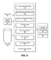
- FIG. 8 is a block diagram of an exemplary embroidery design renderer.
- FIG. 9 is a flowchart of an exemplary method for rendering an embroidered image of an embroidery design.
- FIG. 10 is a block diagram of a networked system in which embodiments of the invention may operate.
- Embodiments of the invention described herein employ a novel hybridization of the model-based and data-driven approaches described in the background section.
- embodiments of the invention utilize a parametric approach to texture mapping.
- Many of the design choices in the embodiments herein described are specific to embroidery visualization and yield results superior to those attainable by existing techniques.
- the performance of the system is suitable for use in interactive applications.
- Embroidery data used as input to such a machine typically consists of a series of x,y coordinates specifying the locations at which stitches (i.e., needle penetrations) should be placed. Stitch length and a rotational angle of the stitch relative to a predefined zero rotation can be determined based on the relative coordinates of the two needle penetrations.
- Wireframe formats typically include a set of wireframe primitives that describe regions using control points and specify properties about how that region should be stitched.
- An example of a wireframe primitive might be an area that should be stitched using a fill stitch with a given density and stitch angle. This higher-level wireframe primitive can then be converted into individual stitch representations by a stitch engine.
- Another traditional method for representing embroidery design data is using a stitch-based format which specifies individual stitches or needle impressions. This is the format that is usually required by an embroidery machine.
- An instruction in a stitch-based format might be represented as “place needle at (2,3), place needle at (5,4), trim, change color, place needle at (3,3), place needle at (6,5), trim . . . ”. If the file specifies needle impressions or stitch points, then the points usually have a type associated with them such as stitch, needle up, or trim.
- an embroidery rendering technique based on a parametric texture model is utilized to render embroidery designs based on stitch representations.
- an embroidery design renderer in accordance with embodiments of the invention quickly draws a simulated image of an embroidery design that appears highly real.
- FIG. 1 there is illustrated an exemplary image 100 of a simulated embroidered design image.
- Each individual stitch in the design is rendered as a rectangle primitive 120 textured with an appropriate image 121 of a stitch.
- the rendering technique employs texture mapping at the individual stitch level, and selects appropriate textures for each stitch based on the length and rotation of the stitch and the lighting angle of the source light.
- the parametric texture model is based in part on texture mapping.
- Texture mapping is the act of taking an image, and placing it on top of some sort of simple graphics primitive. Drawing the rectangle primitives corresponding to the positions of the stitches is a straight-forward procedure that is well-known in the art.
- obtaining and selecting a texture that realistically simulates an actual embroidery stitch presents greater challenges and has not heretofore been achieved. While one might consider simply stretching, compressing, or cropping an image of an individual thread to fit the rectangle primitives, as illustrated in the examples shown in FIG. 2 , the resulting simulated embroidery image does not realistically represent how the embroidered design will appear when physically stitched. First, since threads internally have twists, the image looks unrealistic if it stretched by any significant amount. Second, if an image of a thread is cropped, the middle section may accurately represent the middle portion of an actual stitch, but the ends appear obviously cut off since the stitch penetrations into the fabric are not simulated and do not have the correct lighting.
- FIG. 3 shows an image 300 of a palette 305 containing multiple stitches 310 of various lengths.
- Individual stitch images 310 can be extracted from the image 300 , for example by cropping the areas of the image 300 surrounding a stitch 310 of interest.
- each stitched column contains stitches of the same length, and the stitch length is different between columns.
- the start and end of each stitch is visible—notice how it gets darker at the endpoints where the stitch penetrates the fabric.
- texturing the rectangles using images of real stitches, including the start and end points greatly improves the realism of the rendered design.
- An embroidery design renderer in accordance with embodiments of the invention render the stitches of the embroidery design using texture mapping with images of actual stitches, for example stitches that are selected from the image of FIG. 3 .
- a rectangle primitive corresponding to the length and width of each stitch is generated and placed on the rendering canvas (i.e., an area on a display screen), and a corresponding stitch image having a length (in pixels) that is closest to the size of the rectangle that is to be textured is obtained and used as texture for the corresponding rectangle primitive associated with the stitch being rendered.
- all of the stitches are oriented in the same direction and are illuminated by the same light source and thus at the same lighting angle.
- stitches of the same length and rotation have very similar lighting effects.
- the stitches of a design may be oriented at different rotational angles relative to the light source and to one another. The lighting angle and thus the lighting effects such as illumination and shadowing are independent of the rotation of the stitches. For example, referring to FIGS.
- FIG. 4A-4D if one observes an object 400 (such as the Arrow) in real space that is illuminated from above left, one will observe illuminated areas 402 near the above-left of the object and shadows 404 cast below-right the object 400 no matter what the rotation of the actual object 400 .
- the Arrow object 400 is rotated pointing up at 0° in FIG. 4A , rotated to 90° in FIG. 4B , 180° in FIG. 4C , and 270° in FIG. 4D .
- the illuminated areas 402 are generally at the upper left and the shadows are generally toward the lower right.
- individual embroidery stitches may be stitched at many different rotations in a single design, as illustrated at 110 in FIG. 1 , and the lighting effects (e.g., illumination, shadowing) may fall on different areas of differently oriented stitches.
- the renderer When using texture mapping to render a design having stitches oriented at different rotational angles, the renderer must account for the fact that the imaged lighting effects will rotate with the image of the stitch, which would not be case when an actual physical stitch is rotated relative a light source. For example, if a photograph were to be taken of the Arrow object 400 with the object and light source oriented as shown in FIG. 4A , and then the photograph were rotated by 90°, as shown in FIG. 5 , the illumination areas 402 and shadowing 404 have also rotated by 90°.
- the illumination areas 402 are more toward the upper right (instead of upper left) and the shadow areas 404 appear at the lower left (instead of lower right).
- the rectangle primitive of a rotated stitch cannot be textured by merely rotating an image of a stitch taken at a different stitch rotation with the same lighting angle.
- the renderer should texture the corresponding rectangle primitive with an image of the stitch taken at a lighting angle corresponding to the relative lighting angle between the light source and the rotated stitch. This requires multiple stitch images taken from different lighting angles.
- images of multiple stitches for each of multiple different stitch lengths are obtained over a plurality of different source light angles.
- FIG. 6 graphically illustrates one technique for collecting the required images.
- a camera 610 is positioned a fixed distance in front of a hooped stitch palette.
- the palette 605 is a textile stitched with one or more stitches, such as 305 in FIG. 3 , and is framed in a hoop 630 .
- the palette implements green stitches on a red substrate. These colors are preferable as they are very distinct for good decomposition (just like green-screen or blue-screen video).
- An off-camera light source 620 is rotated around the palette in increments (such as 16°) over a full 360° rotation. Individual stitches (such as 310 shown in FIG. 3 ) can be extracted from the photographs and inserted into a database containing individual stitch images of different stitch lengths and different lighting angles.
- FIG. 7A shows a collection of stitch images arranged in rows by stitch length and columns by source lighting angle. Indexing the images in this manner allows simple selection of appropriate stitch textures for use in texture mapping an embroidery design.
- the relative lighting angle, RAL is then computed as the difference between the illumination angle, I, and the stitch rotational angle, R.
- the column in the stitch image database 700 corresponding to a lighting angle closest to the computed relative lighting angle may then be selected, as illustrated at 730 in FIG. 5D .
- multiple images of different stitches of the same length and lighting angle are collected and usable as an appropriate texture for a stitch of corresponding length and lighting angle.
- one of the multiple images having the same stitch length and lighting angle may be selected at random, or according to a selection algorithm, to add variability to the rendered image—thus, not all stitches having the same stitch length and lighting angle appear exactly the same in the simulated embroidery design image.
- the embroidery design renderer textures the rectangle primitive 120 with the selected stitch image 121 , as best shown at 110 in FIG. 1 .
- This process is repeated for all the stitch representations in the embroidery design, and results in a very real-looking simulated embroidery design image.
- the image database 700 may contain images of stitches taken at not only at varying stitch lengths and lighting angles, but also using different thread colors. The image database 700 would then be further indexed (along a third dimension, not shown), by color.
- the stitch images may be taken of thread of a known color, and then the color can be changed to the specified stitch color via color transformation algorithms.
- the thread color in a selected stitch image may be transformed from one color to another using the well-known Phong shading algorithm, described in Bui Tuong Phong, “Illumination for Computer Generated Pictures,” Comm. ACM, Vol. 18(6):311-317, June 1975, which is incorporated by reference herein for all that it teaches.
- the texture is formed by the combination (overlay) of different channels. These texture coordinates index a specially prepared image file that contains different coefficients for a Phong-like shader. The components that are combined are the color channel, ambient channel, diffuse coefficient, and specular coefficient.
- the embroidery design renderer 800 receives the stitch length and lighting angle, and produces a 3-channel RGB texture which contains (per pixel):
- the texture is produced by indexing the stitch length and lighting angle to a corresponding stitch image having the nearest stitch length and lighting angle in a database of stitch images of varying stitch lengths taken at varying lighting angles, retrieving the corresponding stitch image, and positioning the retrieved stitch image on a rendering canvas in a position specified in the stitch file.
- each individual stitch is rendered as a rectangle. Texture coordinates within each rectangle, ranging from 0 ⁇ u ⁇ 1 and 0 ⁇ v ⁇ 1, are used to index the aforementioned stitch images which comprise, at each pixel, coefficients for a Phong-like shader. These coefficients (diffuse and specular) are combined with the color channel and ambient channel to determine the pixel color in the resulting image.
- the diffuse and specular coefficients from the texture are the geometry-dependent terms in the Phong shading equation. These are computed from the actual stitch image, on a pixel-by-pixel basis, which differs substantially from the traditional computer graphics approaches (such as described in the '283 Publication discussed in the background section) which determine these coefficients based on shape information (e.g., full 3D models or surface normals for bump mapping).
- the diffuse coefficient combined with the color channel provides the general shading for the stitches. It gets the general idea across, but does not have the sparkle of real thread. Adding specular highlights produces the look of reflected light. Preferably, this combination should be performed in linear gamma (1.0) instead of display gamma (typically 1.8 or 2.2).
- the ambient channel accounts for some global illumination and subsurface scattering effects (since the threads are translucent).
- the color of a given pixel in the stitch image is affected by the diffuse component, D, which is the component affected by the observed color, and the specular component, S, which depicts the reflection of the light.
- D the component affected by the observed color
- specular component S
- D the specular component
- S the specular component
- D and S are RGB (Red, Green, Blue display channels).
- D and S are RGB (Red, Green, Blue display channels)
- P new aD new +bS. Since the thread color and light color is known at the time the images are acquired, we can solve for a and b and store this as the texture.
- the threads are green and the light is white when the images are taken
- To transform to a different color one can multiply the thread colors by the diffuse image and add in the specular component.
- the embroidery design renderer selects a stitch image having a stitch length and lighting angle that most closely corresponds to the stitch length and lighting angle of the stitch to be rendered. If a stitch image having an intermediate lighting angle were desired, images corresponding to the two closest lighting angles could be selected and the pixel values could be linearly interpolated only if the desired color is that of the actual images. To produce a thread of a different color, as discussed above, it is not sufficient to just tint the image due to the existence of specular highlights, and it would therefore be necessary to separate out the components of the image.
- FIG. 8 a block diagram depicting a computer system for processing of embroidery stitch data by the embroidery design renderer 800 in accordance with a preferred embodiment of the present invention is shown. It should be understood that the methods and systems exemplified in embodiments described herein apply equally to any computer system, regardless of whether the computer system is a complex multi-user computing system or a single user device such as a personal computer, workstation, laptop, notepad, tablet, personal digital assistant (PDA), cellular phone, or other such device.
- PDA personal digital assistant
- the embroidery design renderer 800 receives a lighting angle 801 from which the illumination angle can be determined. In an embodiment, this is the azimuth of the light source. In an alternative embodiment, the lighting angle is the actual illumination angle.
- the embroidery design renderer also receives embroidery design stitch data 802 typically in the form of a stitch file containing one or more stitch representations from which the length, color, rotation, and position of each stitch of the design is determinable.
- the embroidery design renderer 800 processes each stitch representation from the embroidery design stitch data 802 .
- a number of components of the embroidery design renderer 800 process each stitch representation in the embroidery design stitch data 802 .
- the embroidery design renderer 800 includes a Stitch Length Determination component 810 , a Stitch Rotational Angle Determination component 820 , a Relative Light Angle Determination component 830 , a Color Determination component 840 , a Stitch Image Retrieval component 850 , a Color Translator component 860 (for some embodiments), and a Stitch Image Positioner component 870 .
- the Stitch Length Determination component 810 extracts the start and end coordinates from the stitch representation and determines the length of a stitch in display pixels (it is assumed that all stitches are the same width).
- the Stitch Rotational Angle Determination component 820 determines the stitch angle relative a predetermined reference (e.g., vertical at 0°) based on the start and end coordinates extracted from the stitch representation.
- a predetermined reference e.g., vertical at 0°
- the Relative Lighting Angle Determination 830 component 830 determines the relative lighting angle between the illumination angle (which is determined based on the input Lighting Angle 801 ) and the stitch rotational angle calculated by the Stitch Rotational Angle Determination component 820 .
- the Lighting Angle is the azimuth angle measured between a predetermined positional reference vector (i.e., a predetermined positional “North” coinciding with vertical or 0°) and the directional vector of a light source illuminating the stitch that is to be rendered (hereinafter referred to as the “azimuth angle”).
- the illumination angle is the angle of illumination, which is 180° from the azimuth.
- the Lighting Angle is simply the illumination angle itself.
- the Color Determination component 840 extracts the thread color from the stitch representation.
- the Stitch Image Retrieval component 850 accesses the Stitch Images database 805 and selects an appropriate stitch image using the calculated Stitch Length and Relative Light Angle as an index into the database. If the database includes images of different colored threads, the color is also used to index into the database.
- the Color Translator component 860 translates the retrieved image to the desired color, for example using the Phong shading algorithm described previously.
- the Stitch Image Positioner component 870 then places the retrieved image on a rendering canvas 890 in a position corresponding to a stitch position in the design as extracted from the stitch representation.
- the rendering canvas 890 is an image file.
- the rendering canvas is a display screen.
- a method of operation of an embroidery design renderer in accordance with an exemplary embodiment is illustrated by the flowchart illustrated in FIG. 9 .
- the embroidery renderer obtains the lighting angle (step 901 ) and accesses a stitch file containing stitch representations for an embroidery design (step 902 ).
- the embroidery design renderer processes the stitch representations, one by one accessing the stitch representation (step 903 ), determining the stitch length (step 904 ), determining the relative lighting angle between the illumination angle and the stitch rotational angle (step 906 ), obtaining a stitch image from the stitch image database which corresponds to the determined stitch length and relative lighting angle (step 907 ), and placing the obtained stitch image on a rendering canvas in a position corresponding to stitch position in the embroidery design (step 908 ). Processing continues until all stitches are processed (step 910 ).
- the stitching can be rendered in real-time so that each stitch appears in order on a display screen in the order that it would be processed by the embroidery machine. Generating a slight delay between rendering each stitch on the display screen simulates an animation of the rendering (steps 911 and 912 ).
- the rendered image can be saved to an image file (steps 913 , 914 ), which can presented all at once on a user's display screen, or can be uploaded to a requesting client for remote display.
- animation of moving light can be simulated by rerendering the embroidery design using different lighting angles (steps 915 , 916 ) and sequentially displaying the rerendered images on a display screen.
- FIG. 10 is a block diagram illustrating an exemplary system in which embodiments of the invention may operate.
- a client computer 10 includes one or more processors 11 that perform computation and control functions of the client computer system 10 .
- Processor(s) 11 execute a design tool program 15 and may further execute a browser program 17 .
- the design tool program 15 may execute within the browser program 17 .
- the browser program 17 and design tool program 15 comprise program instructions stored in non-transitory computer readable program memory.
- the Browser program 17 may be used to access, via a network 50 , a website hosted by a server computer system 20 . Web pages 33 of a website may be stored in non-transitory computer readable memory 32 that is accessible to the server computer 20 .
- the server computer 20 also includes one or more processors 21 that perform computation and control functions of the client computer system 20 .
- Processor(s) 21 execute a webhosting program 27 that receives web page requests from client computer 10 , retrieves requested web pages from memory 32 , and sends the requested web pages to client computer 10 .
- At least one web page may require the services of a design tool program 25 , which may reside on the server computer 20 or may be uploaded to the client for execution by the client computer 10 .
- the design tool program 25 may allow a client to select or input an embroidery design, which may already be in the stitch representation format required by embroidery machines, or which may be converted using a translation tool such as that described in U.S. Pat. No. 6,836,695 to Goldman, to the stitch representation format.
- the design tool 25 may include a preview tool 26 , which communicates with an embroidery design renderer 800 residing on the server computer 20 to render a preview image 40 of the selected design.
- the preview image 40 may be saved in non-transitory computer readable storage at the server and transmitted via the network 50 to the client computer 10 , where it is displayed on the user's display screen 19 .
- individual rendered stitches can be sequentially sent from the server computer 20 to the client computer 10 and displayed on the client's display screen 19 .
- the invented method and apparatus described and illustrated herein may be implemented in software, firmware or hardware, or any suitable combination thereof.
- the methods are implemented in software, and the apparatuses and systems are implemented using a combination of hardware and software for purposes of low cost and flexibility.
- the method and apparatus of the invention may be implemented by a computer or microprocessor process in which instructions are executed, the instructions being stored for execution on one or more non-transitory computer-readable mediums and being executed by any suitable instruction processor or combination of instruction processors.
- Alternative embodiments are contemplated, however, and are within the spirit and scope of the invention.
Abstract
Description
-
- Alpha transparency (in the red (R) channel)
- The diffuse coefficient (in the green (G) channel)
- The specular coefficient (in the blue (B) channel)
Claims (19)
Priority Applications (6)
| Application Number | Priority Date | Filing Date | Title |
|---|---|---|---|
| US12/911,521 US8818773B2 (en) | 2010-10-25 | 2010-10-25 | Embroidery image rendering using parametric texture mapping |
| PCT/US2011/042608 WO2012060907A2 (en) | 2010-10-25 | 2011-06-30 | Embroidery image rendering using parametric texture mapping |
| AU2011324027A AU2011324027A1 (en) | 2010-10-25 | 2011-06-30 | Embroidery image rendering using texture database |
| CA2813807A CA2813807A1 (en) | 2010-10-25 | 2011-06-30 | Embroidery image rendering using parametric texture mapping |
| CN2011800514067A CN103180880A (en) | 2010-10-25 | 2011-06-30 | Embroidery image rendering using parametric texture mapping |
| EP11735727.7A EP2633497A2 (en) | 2010-10-25 | 2011-06-30 | Embroidery image rendering using texture database |
Applications Claiming Priority (1)
| Application Number | Priority Date | Filing Date | Title |
|---|---|---|---|
| US12/911,521 US8818773B2 (en) | 2010-10-25 | 2010-10-25 | Embroidery image rendering using parametric texture mapping |
Publications (2)
| Publication Number | Publication Date |
|---|---|
| US20120101790A1 US20120101790A1 (en) | 2012-04-26 |
| US8818773B2 true US8818773B2 (en) | 2014-08-26 |
Family
ID=44628873
Family Applications (1)
| Application Number | Title | Priority Date | Filing Date |
|---|---|---|---|
| US12/911,521 Expired - Fee Related US8818773B2 (en) | 2010-10-25 | 2010-10-25 | Embroidery image rendering using parametric texture mapping |
Country Status (6)
| Country | Link |
|---|---|
| US (1) | US8818773B2 (en) |
| EP (1) | EP2633497A2 (en) |
| CN (1) | CN103180880A (en) |
| AU (1) | AU2011324027A1 (en) |
| CA (1) | CA2813807A1 (en) |
| WO (1) | WO2012060907A2 (en) |
Cited By (2)
| Publication number | Priority date | Publication date | Assignee | Title |
|---|---|---|---|---|
| US10089049B2 (en) | 2016-03-09 | 2018-10-02 | Pti Marketing Technologies Inc. | Ganged imposition postal sort system |
| US20190051044A1 (en) * | 2017-08-10 | 2019-02-14 | Outward, Inc. | Automated mesh generation |
Families Citing this family (5)
| Publication number | Priority date | Publication date | Assignee | Title |
|---|---|---|---|---|
| JP5615055B2 (en) * | 2010-06-18 | 2014-10-29 | キヤノン株式会社 | Information processing apparatus and processing method thereof |
| US20130335437A1 (en) * | 2011-04-11 | 2013-12-19 | Vistaprint Technologies Limited | Methods and systems for simulating areas of texture of physical product on electronic display |
| US9607411B2 (en) | 2014-04-23 | 2017-03-28 | Ebay Inc. | Specular highlights on photos of objects |
| CN109544668B (en) * | 2017-09-21 | 2022-10-25 | 腾讯科技(深圳)有限公司 | Texture coordinate processing method, terminal device and computer readable storage medium |
| CN113362443B (en) * | 2021-06-30 | 2022-11-18 | 珠海必要工业科技股份有限公司 | Embroidery effect picture generation method and device, storage medium and electronic equipment |
Citations (17)
| Publication number | Priority date | Publication date | Assignee | Title |
|---|---|---|---|---|
| US5009943A (en) * | 1988-10-21 | 1991-04-23 | Stahls' Inc. | Pre-sewn letter and method |
| US5668730A (en) * | 1994-10-14 | 1997-09-16 | Pulse Microsystems Ltd. | Method for automatically generating chain stitches |
| US20040056871A1 (en) | 2000-05-02 | 2004-03-25 | Milliron Timothy S. | Method, apparatus, and computer program product for geometric warps and deformations |
| EP1500735A1 (en) | 2002-04-11 | 2005-01-26 | Shima Seiki Manufacturing Limited | Embroidery simulation method and apparatus, and program and recording medium |
| US20060061585A1 (en) | 1998-11-18 | 2006-03-23 | Microsoft Corporation | View dependent tiled textures |
| EP1676945A1 (en) | 2003-10-15 | 2006-07-05 | Shima Seiki Manufacturing, Ltd. | Embroidery data creation device, embroidery data creation method, and embroidery data creation program |
| US7088374B2 (en) | 2003-03-27 | 2006-08-08 | Microsoft Corporation | System and method for managing visual structure, timing, and animation in a graphics processing system |
| US20070118245A1 (en) * | 2005-11-02 | 2007-05-24 | Goldman David A | Printer driver systems and methods for automatic generation of embroidery designs |
| US20080079727A1 (en) * | 2006-09-30 | 2008-04-03 | Soft Sight, Inc | Method and System for Creating and Manipulating Embroidery Designs Over a Wide Area Network |
| US20090249841A1 (en) | 2008-03-24 | 2009-10-08 | David Aaron Holmes | Mnemonic combination locking system |
| US20090286039A1 (en) * | 2008-05-02 | 2009-11-19 | Paul Weedlun | Printed applique with three-dimensional embroidered appearance |
| US20100106283A1 (en) | 2008-10-23 | 2010-04-29 | Zazzle.Com, Inc. | Embroidery System and Method |
| US20110157226A1 (en) | 2009-12-29 | 2011-06-30 | Ptucha Raymond W | Display system for personalized consumer goods |
| US20110170800A1 (en) | 2010-01-13 | 2011-07-14 | Microsoft Corporation | Rendering a continuous oblique image mosaic |
| US20120259727A1 (en) | 2011-04-11 | 2012-10-11 | Vistaprint Technologies Limited | Method and system for personalizing images rendered in scenes for personalized customer experience |
| US20120256948A1 (en) | 2011-04-11 | 2012-10-11 | Vistaprint Technologies Limited | Method and system for rendering images in scenes |
| US20130335437A1 (en) | 2011-04-11 | 2013-12-19 | Vistaprint Technologies Limited | Methods and systems for simulating areas of texture of physical product on electronic display |
Family Cites Families (5)
| Publication number | Priority date | Publication date | Assignee | Title |
|---|---|---|---|---|
| US6836695B1 (en) | 1998-08-17 | 2004-12-28 | Soft Sight Inc. | Automatically generating embroidery designs from a scanned image |
| US6397120B1 (en) | 1999-12-30 | 2002-05-28 | David A. Goldman | User interface and method for manipulating singularities for automatic embroidery data generation |
| JP3826349B2 (en) * | 2002-04-30 | 2006-09-27 | 株式会社ゴールドウイン | Embroidery and method for forming the same |
| AU2009205456B2 (en) | 2008-01-14 | 2014-07-17 | Cimpress Schweiz Gmbh | Systems, methods and apparatus for embroidery thread color management |
| CN101859335B (en) * | 2010-05-18 | 2011-09-07 | 南京大学 | Computer-aided crewel embroidery production method |
-
2010
- 2010-10-25 US US12/911,521 patent/US8818773B2/en not_active Expired - Fee Related
-
2011
- 2011-06-30 CN CN2011800514067A patent/CN103180880A/en active Pending
- 2011-06-30 CA CA2813807A patent/CA2813807A1/en not_active Abandoned
- 2011-06-30 AU AU2011324027A patent/AU2011324027A1/en not_active Abandoned
- 2011-06-30 WO PCT/US2011/042608 patent/WO2012060907A2/en active Application Filing
- 2011-06-30 EP EP11735727.7A patent/EP2633497A2/en not_active Withdrawn
Patent Citations (19)
| Publication number | Priority date | Publication date | Assignee | Title |
|---|---|---|---|---|
| US5009943A (en) * | 1988-10-21 | 1991-04-23 | Stahls' Inc. | Pre-sewn letter and method |
| US5668730A (en) * | 1994-10-14 | 1997-09-16 | Pulse Microsystems Ltd. | Method for automatically generating chain stitches |
| US7271811B2 (en) * | 1998-11-18 | 2007-09-18 | Microsoft Corporation | View dependent tiled textures |
| US20060061585A1 (en) | 1998-11-18 | 2006-03-23 | Microsoft Corporation | View dependent tiled textures |
| US20040056871A1 (en) | 2000-05-02 | 2004-03-25 | Milliron Timothy S. | Method, apparatus, and computer program product for geometric warps and deformations |
| EP1500735A1 (en) | 2002-04-11 | 2005-01-26 | Shima Seiki Manufacturing Limited | Embroidery simulation method and apparatus, and program and recording medium |
| US20050149223A1 (en) * | 2002-04-11 | 2005-07-07 | Nobuyuki Takeuchi | Embroidery simulation method and apparatus and program and recording medium |
| US7088374B2 (en) | 2003-03-27 | 2006-08-08 | Microsoft Corporation | System and method for managing visual structure, timing, and animation in a graphics processing system |
| EP1676945A1 (en) | 2003-10-15 | 2006-07-05 | Shima Seiki Manufacturing, Ltd. | Embroidery data creation device, embroidery data creation method, and embroidery data creation program |
| US20070118245A1 (en) * | 2005-11-02 | 2007-05-24 | Goldman David A | Printer driver systems and methods for automatic generation of embroidery designs |
| US20080079727A1 (en) * | 2006-09-30 | 2008-04-03 | Soft Sight, Inc | Method and System for Creating and Manipulating Embroidery Designs Over a Wide Area Network |
| US20090249841A1 (en) | 2008-03-24 | 2009-10-08 | David Aaron Holmes | Mnemonic combination locking system |
| US20090286039A1 (en) * | 2008-05-02 | 2009-11-19 | Paul Weedlun | Printed applique with three-dimensional embroidered appearance |
| US20100106283A1 (en) | 2008-10-23 | 2010-04-29 | Zazzle.Com, Inc. | Embroidery System and Method |
| US20110157226A1 (en) | 2009-12-29 | 2011-06-30 | Ptucha Raymond W | Display system for personalized consumer goods |
| US20110170800A1 (en) | 2010-01-13 | 2011-07-14 | Microsoft Corporation | Rendering a continuous oblique image mosaic |
| US20120259727A1 (en) | 2011-04-11 | 2012-10-11 | Vistaprint Technologies Limited | Method and system for personalizing images rendered in scenes for personalized customer experience |
| US20120256948A1 (en) | 2011-04-11 | 2012-10-11 | Vistaprint Technologies Limited | Method and system for rendering images in scenes |
| US20130335437A1 (en) | 2011-04-11 | 2013-12-19 | Vistaprint Technologies Limited | Methods and systems for simulating areas of texture of physical product on electronic display |
Non-Patent Citations (11)
| Title |
|---|
| "Notification of Transmittal of the International Search Report and the Written Opinion of the International Searching Authority, or the Declaration," mailed Aug. 3, 2012 for International Application No. PCT/US2012/033104. |
| "Notification of Transmittal of the International Search Report and the Written Opinion of the International Searching Authority, or the Declaration," mailed Jul. 25, 2012 for International Application No. PCT/US2012/033096. |
| Ding, et al., "Semi-Automatic Image Personalization Tool for Variable Text Insertion and Replacement," Proceedings of the International Society for Optical Engineering SPIE, vol. 7540, pp. 1-11, XP-002678817, 2010. |
| Final Office Action dated Oct. 29, 2013 for U.S. Appl. No. 13/084,550. |
| Gilmours Wholesale Food & Beverage, "Webshot Help and Frequently Asked Questions," Retrieved from the Internet: URL: https://www.gilmours.co.nz/content/frequently-asked-questions.pdf, 5 pages, updated Mar. 22, 2011. |
| Gilmours Wholesale Food & Beverage, "Webshot Help and Frequently Asked Questions," Retrieved from the Internet: URL: https://www.gilmours.co.nz/content/frequently—asked—questions.pdf, 5 pages, updated Mar. 22, 2011. |
| Notification of Transmittal of the International Search Report and the Written Opinion of the International Searching Authority, or the Declaration, mailed on Jul. 25, 2012 for International Application No. PCT/US2011/042608. |
| Office Action dated Jan. 17, 2013 for U.S. Appl. No. 13/084,550. |
| Wauters, "DAZZ Offers a Way to Preview PhotoGifts Prior to Purchase," http://techcrunch.com; Feb. 28, 2009, Retrieved from the Internet: URL: http://techcrunch.com/2009/02/28/dazz-offers-a-way-to-preview-photo-gifts-prior-to-purchase/. |
| White et al., "Retexturing Single Views Using Texture and Shading," Computer Vision-ECCV 2006, Part IV, Lecture Notes in Computer Science 3954, pp. 70-81, Jan. 1, 2006. |
| Yen, et al., "Web-Based Virtual Reality Catalog in Electronic Commerce," Proceedings of the 33rd Hawaii International Conference on System Sciences, pp. 1-10, Jan. 4-7, 2000. |
Cited By (5)
| Publication number | Priority date | Publication date | Assignee | Title |
|---|---|---|---|---|
| US10089049B2 (en) | 2016-03-09 | 2018-10-02 | Pti Marketing Technologies Inc. | Ganged imposition postal sort system |
| US10891094B2 (en) | 2016-03-09 | 2021-01-12 | Pti Marketing Technologies Inc. | Ganged imposition sort system |
| US20190051044A1 (en) * | 2017-08-10 | 2019-02-14 | Outward, Inc. | Automated mesh generation |
| US10650586B2 (en) * | 2017-08-10 | 2020-05-12 | Outward, Inc. | Automated mesh generation |
| US11935193B2 (en) | 2017-08-10 | 2024-03-19 | Outward, Inc. | Automated mesh generation |
Also Published As
| Publication number | Publication date |
|---|---|
| WO2012060907A3 (en) | 2012-09-07 |
| WO2012060907A2 (en) | 2012-05-10 |
| EP2633497A2 (en) | 2013-09-04 |
| CN103180880A (en) | 2013-06-26 |
| CA2813807A1 (en) | 2012-05-10 |
| US20120101790A1 (en) | 2012-04-26 |
| AU2011324027A1 (en) | 2013-05-02 |
Similar Documents
| Publication | Publication Date | Title |
|---|---|---|
| US8818773B2 (en) | Embroidery image rendering using parametric texture mapping | |
| DE102005035012B4 (en) | High performance shading of large volumetric data using partial screen space derivatives | |
| Schott et al. | A directional occlusion shading model for interactive direct volume rendering | |
| Owada et al. | Volumetric illustration: Designing 3d models with internal textures | |
| Hameeuw et al. | New visualization techniques for cuneiform texts and sealings | |
| US8970586B2 (en) | Building controllable clairvoyance device in virtual world | |
| JP7235875B2 (en) | Point cloud colorization system with real-time 3D visualization | |
| US20170124754A1 (en) | Point and click lighting for image based lighting surfaces | |
| Lallensack et al. | Photogrammetry in ichnology: 3D model generation, visualisation, and data extraction | |
| US10325402B1 (en) | View-dependent texture blending in 3-D rendering | |
| US11769195B2 (en) | Systems and methods for visualizing wall coverings in an image of a scene | |
| EP0789893A1 (en) | Methods and apparatus for rapidly rendering photo-realistic surfaces on 3-dimensional wire frames automatically | |
| JP2004199301A (en) | Image processor | |
| US11113868B2 (en) | Rastered volume renderer and manipulator | |
| US11138791B2 (en) | Voxel to volumetric relationship | |
| Jaspe et al. | Web-based multi-layered exploration of annotated image-based shape and material models | |
| Gierlinger et al. | Rendering techniques for mixed reality | |
| Güssefeld et al. | Are reflectance field renderings appropriate for optical flow evaluation? | |
| Feldman et al. | Interactive 2D to 3D stereoscopic image synthesis | |
| Birukov et al. | Elaboration of visualization modes for lighting simulation in catia cad system | |
| Lum et al. | Interactivity is the key to expressive visualization | |
| Liu | A novel Mesa-based OpenGL implementation on an FPGA-based embedded system | |
| Wu et al. | Editable texture map generation and optimization technique for 3D visualization presentation | |
| Krumpen et al. | OctreeBTFs–A compact, seamless and distortion-free reflectance representation | |
| Hwang et al. | Video-based weathering gallery |
Legal Events
| Date | Code | Title | Description |
|---|---|---|---|
| AS | Assignment |
Owner name: VISTAPRINT TECHNOLOGIES LIMITED, BERMUDA Free format text: ASSIGNMENT OF ASSIGNORS INTEREST;ASSIGNORS:HSU, EUGENE;GOLDMAN, DAVID A.;REEL/FRAME:025198/0651 Effective date: 20101025 |
|
| AS | Assignment |
Owner name: JPMORGAN CHASE BANK, N.A., AS ADMINISTRATIVE AGENT Free format text: SECURITY AGREEMENT;ASSIGNOR:VISTAPRINT SCHWEIZ GMBH;REEL/FRAME:031371/0384 Effective date: 20130930 |
|
| AS | Assignment |
Owner name: VISTAPRINT LIMITED, BERMUDA Free format text: ASSIGNMENT OF ASSIGNORS INTEREST;ASSIGNOR:VISTAPRINT TECHNOLOGIES LIMITED;REEL/FRAME:031394/0311 Effective date: 20131008 |
|
| AS | Assignment |
Owner name: VISTAPRINT SCHWEIZ GMBH, SWITZERLAND Free format text: ASSIGNMENT OF ASSIGNORS INTEREST;ASSIGNOR:VISTAPRINT LIMITED;REEL/FRAME:031394/0742 Effective date: 20131008 |
|
| STCF | Information on status: patent grant |
Free format text: PATENTED CASE |
|
| AS | Assignment |
Owner name: CIMPRESS SCHWEIZ GMBH, SWITZERLAND Free format text: CHANGE OF NAME;ASSIGNOR:VISTAPRINT SCHWEIZ GMBH;REEL/FRAME:036277/0592 Effective date: 20150619 |
|
| MAFP | Maintenance fee payment |
Free format text: PAYMENT OF MAINTENANCE FEE, 4TH YEAR, LARGE ENTITY (ORIGINAL EVENT CODE: M1551) Year of fee payment: 4 |
|
| FEPP | Fee payment procedure |
Free format text: MAINTENANCE FEE REMINDER MAILED (ORIGINAL EVENT CODE: REM.); ENTITY STATUS OF PATENT OWNER: LARGE ENTITY |
|
| LAPS | Lapse for failure to pay maintenance fees |
Free format text: PATENT EXPIRED FOR FAILURE TO PAY MAINTENANCE FEES (ORIGINAL EVENT CODE: EXP.); ENTITY STATUS OF PATENT OWNER: LARGE ENTITY |
|
| STCH | Information on status: patent discontinuation |
Free format text: PATENT EXPIRED DUE TO NONPAYMENT OF MAINTENANCE FEES UNDER 37 CFR 1.362 |
|
| FP | Lapsed due to failure to pay maintenance fee |
Effective date: 20220826 |