US8239831B2 - Visual interface for automated software testing - Google Patents
Visual interface for automated software testing Download PDFInfo
- Publication number
- US8239831B2 US8239831B2 US11/548,572 US54857206A US8239831B2 US 8239831 B2 US8239831 B2 US 8239831B2 US 54857206 A US54857206 A US 54857206A US 8239831 B2 US8239831 B2 US 8239831B2
- Authority
- US
- United States
- Prior art keywords
- interface portion
- test
- visual
- screen
- window
- Prior art date
- Legal status (The legal status is an assumption and is not a legal conclusion. Google has not performed a legal analysis and makes no representation as to the accuracy of the status listed.)
- Active - Reinstated, expires
Links
- 230000000007 visual effect Effects 0.000 title claims abstract description 58
- 238000013522 software testing Methods 0.000 title description 7
- 238000012360 testing method Methods 0.000 claims abstract description 137
- 238000000034 method Methods 0.000 claims abstract description 27
- 230000000051 modifying effect Effects 0.000 claims abstract description 7
- 230000009471 action Effects 0.000 claims description 87
- 238000012986 modification Methods 0.000 claims description 2
- 230000004048 modification Effects 0.000 claims description 2
- 238000012795 verification Methods 0.000 abstract description 11
- 238000011990 functional testing Methods 0.000 abstract description 7
- 238000013515 script Methods 0.000 description 17
- 230000008569 process Effects 0.000 description 8
- 238000013459 approach Methods 0.000 description 7
- 230000006870 function Effects 0.000 description 4
- 238000012552 review Methods 0.000 description 4
- 230000006399 behavior Effects 0.000 description 2
- 230000008859 change Effects 0.000 description 2
- 238000004891 communication Methods 0.000 description 2
- 238000004590 computer program Methods 0.000 description 2
- 238000011161 development Methods 0.000 description 2
- 230000006872 improvement Effects 0.000 description 2
- 230000007246 mechanism Effects 0.000 description 2
- 230000001360 synchronised effect Effects 0.000 description 2
- 230000001960 triggered effect Effects 0.000 description 2
- 238000004458 analytical method Methods 0.000 description 1
- 238000004364 calculation method Methods 0.000 description 1
- 238000010276 construction Methods 0.000 description 1
- 238000013461 design Methods 0.000 description 1
- 238000010586 diagram Methods 0.000 description 1
- 238000011156 evaluation Methods 0.000 description 1
- 230000014509 gene expression Effects 0.000 description 1
- 238000004519 manufacturing process Methods 0.000 description 1
- QSHDDOUJBYECFT-UHFFFAOYSA-N mercury Chemical compound [Hg] QSHDDOUJBYECFT-UHFFFAOYSA-N 0.000 description 1
- 229910052753 mercury Inorganic materials 0.000 description 1
- 230000003287 optical effect Effects 0.000 description 1
- 238000000275 quality assurance Methods 0.000 description 1
- 239000007787 solid Substances 0.000 description 1
- 230000003068 static effect Effects 0.000 description 1
- 238000012956 testing procedure Methods 0.000 description 1
- 230000007704 transition Effects 0.000 description 1
- 238000013519 translation Methods 0.000 description 1
Images


Classifications
-
- G—PHYSICS
- G06—COMPUTING; CALCULATING OR COUNTING
- G06F—ELECTRIC DIGITAL DATA PROCESSING
- G06F11/00—Error detection; Error correction; Monitoring
- G06F11/36—Preventing errors by testing or debugging software
- G06F11/3664—Environments for testing or debugging software
Definitions
- This invention relates generally to automated testing of computer software programs and more particularly to automated software quality through automated functional testing using graphical user interfaces.
- Software testing is viewed as an obstacle to production because it is time consuming and the costs of not testing are theoretical and uncertain. Consequently, software testing is often neglected.
- One way to balance deployment time with higher software quality resulting from thorough testing is to make testing and development as efficient as possible.
- test scripts for testing a software application.
- These scripts are conventionally written in a general purpose programming language such as Visual Basic, C++ or Java, or in a proprietary language focused on test scripts.
- the scripts abstractly represent actions that are to be performed by the application under test.
- the scripts themselves, like computer programs, are compiled and then executed against the application under test.
- a software tool called Mercury QuickTest Pro provides a “screenshot” view that gives users a visual context for creating and maintaining test scripts while seeing the controls they are manipulating.
- a tree and grid interface textually describes the actions relative to the screenshot view.
- the user is not provided with a visual interface for understanding the relationship of each action and each window to the overall scope of the script. Rather, a hierarchical tree view indicates the relationship of each window to each step in the test script.
- the user must still deal with significant abstraction.
- technical language is still used in much of the text presented to the user, making it difficult for non-technical personnel to make use of such tool.
- translation between the visual interface and a script remains a requirement.
- CERTIFY product produced by Worksoft, Inc. of Dallas, Tex. is marketed as using a “progression testing” approach that requires no scripts or other programming.
- An expert has to develop a testing execution engine for at least some environments. The engine accepts a limited set of Keywords to be input from tables. The test processes, then, are defined based on the tables.
- the items in the tables include objects (e.g., “NewBtn PushButton”), actions (e.g., “Press”), descriptions (e.g., “Press NewBtn PushButton”), and what to do on pass or on fail (e.g., “Continue”).
- TestPartner product from assignee Compuware Corporation
- Visual Navigator a tool that simplifies some of the more arcane aspects of creating, executing, and managing scripts.
- a system and a method for software testing and quality assurance provides a visually oriented interface that includes actual screen views for each window that is automated within the application under test.
- the system captures a screen shot of each window against which it records user actions, and then matches up the known starting point of the screen shot with the known location of enumerated controls within the window.
- This information is stored in conjunction with the screenshot. Accordingly, the user is able to review the exact screens being automated, as well as the flow of information; identify all supported controls on each window; edit existing transactions, also called “Visual tests”, including adding new control information visually; and perform such actions even when the application under test is not itself available (e.g., when it is off line).
- a screen is displayed to notify the user when recording of a new visual test has begun.
- a visual interface geared for novice users includes an application window, also called “Screen Preview”, an action window, also called test steps, a properties window and a storyboard window.
- the application window is a screen shot of the window being automated in the application under test.
- the action window is a list of actions displayed within the application window, as well as logic that occurs within the context of the transaction but does not directly manipulate the graphical user interface of the application under test.
- the properties window displays the attributes associated with an item or step the user selects.
- the storyboard window shows a sequence of application windows being automated. In one embodiment, the application window appears to the left of the action window, the property window below the application window and the storyboard window appears below the property and action windows. In a further embodiment, the storyboard window uses “thumbnail” screenshots to depict the windows under automation.
- highlighting within the application window, the action window and the storyboard window is synchronized so as to help direct the user to the appropriate context for any particular portion of the testing. For example, when a user selects a particular action in the action window, the corresponding graphical user interface component of the application under test is highlighted in the application window, as is the appropriate “thumbnail” in the storyboard window.
- actions are visually editable regardless of whether the application under test is actually available.
- the user performs such editing directly in the application window and in another the user is given the option of editing offline and updating on a screen-by-screen or application-by-application basis when online. In this manner, the user does not need to locate and execute the actual application under test every time a change is made to the desired testing procedure.
- usability of the action window is increased by application of relatively non-technical language in that window, a simple syntactical structure (e.g., ⁇ action> ⁇ object>), and inclusion of visually descriptive icons in the action window's list of actions.
- a simple syntactical structure e.g., ⁇ action> ⁇ object>
- a results window includes a portion with a list of tests executed and a context-sensitive portion providing further details.
- results are broken down into simple to understand levels of severity including errors, warnings, and informational messages. Categorization of such levels is user-controllable on an individual basis as well as globally, to permit the user or an administrator to modify levels as may be needed.
- the context-sensitive portion of the results window displays application, action, property and storyboard portions to visually show what happened during execution of a particular test.
- a startup window for each user integrates recent transactions; new transactions; assigned tasks, notes and other collaboration information; support and “getting started” information to enhance usability.
- system is configured to allow a user to flag elements for follow-up directly in the results or transaction window, and to allow a user to annotate with text, voice, or file attachments directly in the application window.
- the system is also configured to allow a user to add notes to the results or transaction widows. Flags are to facilitate collaboration between users, and notes are for informational purposes.
- the system permits a user to print tests, results, screenshots and descriptions.
- the print dialog allows users to decide how much information they wish to print. For example, users may select to print all associated screens, or only selected items.
- FIG. (“FIG.”) 1 illustrates a visual interface geared for novice users to control the automation of an Application Under Test (AUT) which includes an Application Window, an Action Window, and a Storyboard Window in accordance with one embodiment of the present invention.
- AUT Application Under Test
- FIG. 2 illustrates one step in the method of using the visual interface shown in FIG. 1 to modify transactions of an automated functional test, where the action being modified is selected, in accordance with one embodiment of the present invention.
- FIG. 3 illustrates a results window which provides users with a broad understanding of the results of the transactions executed on the AUT, in accordance with one embodiment of the present invention.
- FIG. 4 illustrates the results window in which the numbers on each tab and the data displayed within the lower results pane is contextually dependant on the line selected in the upper results pane, in accordance with one embodiment of the present invention.
- FIG. 5 illustrates the results window when the details tab is selected, including a log of results that can be viewed in conjunction with the Application Window to show the actual controls automated, in accordance with one embodiment of the present invention.
- FIG. 6 illustrates an initial task based interface, called the Start Screen, which allows users to select from variety of initial tasks to perform in accordance with one embodiment of the present invention.
- FIG. 7 illustrates an initial screen of a Test Logic Designer that allows users to simply perform a variety of logic functions in accordance with one embodiment of the present invention.
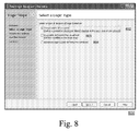
- FIG. 8 illustrates a screen of the Test Logic Designer that is displayed while it is being used to create looping logic in a functional test in accordance with one embodiment of the present invention.
- FIG. 9 illustrates a screen of the Test Logic Designer and the Action Window that is displayed while they are being used to create looping logic in a functional test in accordance with one embodiment of the present invention.
- FIG. 10 illustrates a further screen of the Test Logic Designer that is displayed while it is being used to create looping logic in a functional test in accordance with one embodiment of the present invention.
- FIG. 11 illustrates a screen of the Test Logic Builder that is displayed while it is being used to create looping logic based on the value of a control property, in accordance with one embodiment of the present invention.
- FIG. 12 illustrates a programmed computer in accordance with one embodiment of the present invention.
- FIG. 13 illustrates a condition editor screen in accordance with an embodiment of the present invention.
- FIG. The Figures (“FIG.”) and the following description relate to preferred embodiments of the present invention by way of illustration only. It should be noted that from the following discussion, alternative embodiments of the structures and methods disclosed herein will be readily recognized as viable alternatives that may be employed without departing from the principles of the claimed invention.
- the present invention includes a system and a method for providing a visual interface for creating, maintaining, and, reviewing the results of, automated functional tests of software applications.
- the system includes actual screen views for each window that is automated within the application under test.
- FIG. 12 illustrates an overall flow diagram of one embodiment of this invention with the processes disclosed herein 1290 in one embodiment stored in the storage medium 1230 of a computer, and then copied to memory 1220 during execution.
- FIG. (“FIG.”) 1 illustrates an embodiment with a visual interface 10 , geared for novice users, which includes an Application Window 100 , an Action Window 102 , a Properties Window 126 , and a Storyboard Window 104 .
- the Application Window 100 is the primary visual interface that the “novice” user interacts with to control the automation of each window within the Application Under Test (AUT). It is generated by capturing a screen image 106 of each application window being automated in the AUT. Since the invention knows the coordinates of the application window and all supported controls within it 108 , and since the screenshot 106 originates from a known screen position, the list of enumerated controls can be matched to the screen image accurately.
- the application window matches the known starting point of the screenshot with the known locations of the enumerated controls 108 within the window. This information is stored in conjunction with the screenshot.
- the user can interact with the screenshot of the application (offline) in much the same way that they would interact with the application itself.
- the user is then able to perform a variety of actions without any consideration for whether the actual application under test is currently offline or unavailable. These actions include reviewing the exact screens being automated, reviewing the flow of automation, identifying all supported controls on each window, editing existing transactions and adding new control automation visually.
- the user also is able to inspect the controls displayed, click on a control and modify its automated behavior, and create a verification to test the properties found within a control on the application.
- the Action Window 102 is a “list-based” interface that presents users with a sequential, textual list 110 of the actions that occur within the transaction. It also provides users with an interface for modifying actions 112 . In one embodiment, the Action Window 102 also allows the user to insert logic—commands that do not directly manipulate the GUI of the application under test, but which occur within the flow of the transaction.
- the language used within the Action Window is both simple and plain, as opposed to being codelike or technical jargon. Because (1) the Application Window visually provides the context of the actions, (2) the system knows what kind of control it is automating, and (3) the point of automation is visually specified in the Application Window, a relatively complex sequence of code that would be used in a script based testing environment is reduced to a single, fairly simple action within the Action Window, for example “Select ‘Bauhaus 93’” 114 .
- the Application Window 100 works in conjunction with the Action Window 102 to present the user with the sequence of recorded actions. If an action is selected 114 within the Action Window, the corresponding control 116 is highlighted within the Application Window. This enables the user to quickly associate the action 114 with the application control 116 being automated, even if the application under test is not running.
- the Storyboard Window 104 presents users with the visual sequence of windows being automated 118 , and numeric data 120 that provides the relationship between each window and the recorded actions.
- Each window is depicted as a thumbnail and the windows are arranged in the linear order in which they are automated within the transaction.
- the number above each window 120 relates the numeric sequence of actions performed against each window, and it correlates with the numbers 122 listed in the Action Window.
- the Storyboard windows 118 have three primary purposes. First, they allow the user to visually understand order of windows and actions being executed. The windows provide a miniature visual representation of each window under automation, enabling users to more quickly find a particular point (window) in the automation sequence. Second, the windows allow users to move quickly among windows. By moving window-to-window, the user can quickly navigate through, or jump over, a large number of actions. Third, the windows allow users to quickly and easily rearrange the order that the windows are automated. Users can copy, paste, and drag and drop entire windows and their associated sequence of actions.
- the corresponding lines 114 within the Action Window are also highlighted at once. Similarly, if an item 114 in the Action Window is selected, the corresponding window 124 within the Storyboard is highlighted.
- a “Properties” window is provided.
- Properties Window 126 appears below application 100 .
- Properties Window 126 lists various action items 127 and displays properties of any selected action item 128 .
- selecting an action item also allows the user to edit that action item. Users may also add descriptions to items through the Properties window.
- the Properties Window 126 allows a user to interact with a selected item. If a variable or active data value is selected, the user may edit the item through the Properties Window.
- windows 100 , 102 , 104 , 126 include “header” areas with selection mechanisms (e.g., drop-down menus, icon bars, test logic toolbox) permitting users to readily select tasks pertinent to the windows they are looking at.
- selection mechanisms e.g., drop-down menus, icon bars, test logic toolbox
- a playback dialog is presented on one embodiment that allows a user to set whether the log will be saved into a new test result, overwrite the existing test result or append to the old test result.
- a playback window further allows a user to select how often the program will export results. Options provided to the user include always, only when a test fails, and never.
- the user selects the “Record New . . . ” 604 option from the Start Screen 601 .
- the user interface then transitions to record mode.
- the Application, Action, and Storyboard windows are presented to the user as in FIGS. 1 and 2 . From here they can modify their transaction as desired. The user can also choose to execute their transaction or return to the Start Screen interface 601 to choose another task.
- the Application 100 and Action 102 Windows provide users with the ability to easily edit existing transactions. From directly within these windows, users can add, edit, move/reorder, copy/duplicate, or delete steps within the sequence of recorded actions 110 . The user can delete all actions associated with an entire screen. In the case of editing, the user can modify transactions in offline mode. This is because the system preserves property, enumeration, and visual information of the test. To edit, the user opens the transaction and selects the action to modify 200 . As long as the application screen and controls remain the same, a wide variety of actions can be modified without having access to the application under test.
- the invention provides the user with multiple ways to edit an existing action. These include: (1) Selecting a step from the Action Window 200 , then modifying it through the Properties window 126 (2) Scrolling upward/downward in the Action Window using the scrollbars 202 , highlighting the appropriate item 200 , and then modifying the step 204 . (3) Tabbing through the automated controls 108 in the Application Window 100 and selecting a popup menu that allows the user to modify the action performed against this control.
- Users can also elect to add a new step to the sequence of actions recorded against a given screen. For example, to accomplish this via the Action Window, the user selects the step prior to where they want to add the new action, and then right-clicks to select a pop-up “Insert” menu option to insert “Control From” the “Application Under Test” or “Application Window.” The user then selects the control to be automated, selects the action, and specifies any pertinent data that may need to be entered, such as the text to be typed into an edit control.
- a system in accordance with the invention also allows users to delete, copy, cut, and paste actions in a similar manner. In some embodiments, the system allows a user to repeat actions based on the value of a control property by selecting a corresponding user interface option.
- FIG. 3 illustrates a results window 300 that provides users with a broad understanding of the results of the transactions they executed. It displays the results of the overall transaction; the errors, warnings, or messages generated; and the pass/fail status of any verifications performed.
- the results window 300 includes a portion with a list of tests executed 302 and a context sensitive portion providing further details 304 .
- the top portion of the window 302 provides a summary of the result of each transaction 306 (pass, fail, or potentially “mixed” for a driver that contains both passes and fails), the test cycle 308 , a status 310 that briefly describes the result, the result of any verifications 312 , and notation as to whether an items have been flagged for specific attention 314 .
- the first line of the results is selected by default.
- the lower portion of the window has a tabbed frame that breaks down and provides additional information related to the selected line within the results.
- the tabs are, in order: Summary 316 , Errors 318 , Warnings 320 , Informationals 322 , Verifications 324 , Flags 326 , and Details 328 .
- the summary tab 316 offers information about the status of the transaction, pertinent options and criteria used when executing the transaction, etc.
- the error tab 318 provides a list of runtime errors encountered, details about the errors, and links to help troubleshoot the errors.
- the warnings tab 320 provides a list of any issues encountered that the tool was able to recover from, for example a runtime error that the tool handled, details about the situation, and links to resolve the situation that triggered the warning.
- the informational tab 322 provides a list of any less critical issues or comments logged, and details about the issue.
- the verifications tab 324 provides a list of the verifications executed, distinguishes between passed and failed verifications, and provides some details about the cause of any failures.
- the flags tab 326 provides a list of any issues that have been flagged for additional follow-up. Issues can be flagged based on preconfigured criteria set up by the user, or can be manually flagged by the user during a review of the results (for review by a more experienced user, for example). Each tab contains a number that identifies how many of each item are present (e.g.—1 error 318 , 4 warnings 320 , etc).
- the tabbed pane is context sensitive: If the user selects a different line 400 in the top results window 302 , the numbers on each tab 402 and the data within each pane 304 are updated to reflect information appropriate to the selected transaction.
- the details tab 328 focuses on the technical success or failure of each command and any details associated with the command. As shown in FIG. 5 , when the details tab is selected, it shows a result 500 that can be viewed in conjunction with the Application Window 502 to show the actual controls 510 that were automated. Therefore, in addition to providing information about each step executed 512 in the transaction, the details tab offers the user with a visual link between the results 504 and the application under test 506 . To facilitate this approach, the same “Application Window” 502 used in creating a test is also used to present a screenshot of each window that was automated during execution 506 . Similarly, the properties window 513 is the same format as was used when the test began, displaying the attributes of any items the user selects.
- the same “Storyboard Window” used in creating a test is also used to present a visual sequence of windows being automated, as well as numeric data that provides the relationship between each window and the recorded actions. This allows the user to have a more visual understanding of the automation.
- the Details tab provides information about the result of the step 504 (e.g.—did it result in an error, a warning, etc). For situations where a verification fails or an error is encountered, the system offers a description of the cause 508 . Because there is a visual link between the Details tab 528 and the Application Window 502 , users can scroll through the numbered list of actions 500 , and the applicable control within the Application Window 502 is highlighted. This allows the system to demonstrate the entire sequence of actions to the user from both a textual and visual standpoint.
- Filter criteria include whether a given check was passed or failed, user and events. In some embodiments, additional filter criteria are provided.
- users can choose to view a session as it is running rather than waiting for the transaction log. By clicking on a window, the data the window displays will be updated in real time as the application runs.
- the system is controlled from a task based interface called “Start Screen” 601 .
- Novice users are task oriented, and so they often need guidance in determining what they want to do with the tool.
- the system disclosed herein provides users with a goal oriented approach they understand by identifying common tasks. It also provides users with structure by offering a defined set of tasks that they can choose from.
- the initial task based interface includes a limited selection and a limited variety of tasks to perform, since novice users in general only undertake a handful of “higher level” tasks.
- the initial Start Screen interface is broken down to provide the following options: (1) Visual tests 602 ; (2) Tasks 604 ; (3) Flags 606 ; (4) Help 608 .
- the Visual tests area 602 provides the user with the choice to record new tests or open existing tests. In a preferred embodiment, a list of recent tests is displayed for the user's convenience.
- the Tasks area 604 lists for the user a number of the more common tasks the user might wish to choose.
- the Flags area 606 provides a convenient location for the user to see which recent results have been flagged for special attention.
- the Help 608 area provides for a variety of help and support options including: (1) A tour of the program; (2) Recording, modifying, and managing visual tests; (3) Reviewing results; (4) An index of help topics; (5) View sample visual tests; (6) A section to help the user understand the test steps; (7) Visit technical support, known as Compuware Frontline; (8) Visit the Compuware website.
- the Properties window allows the user to “variabilize data” or “add test data”. Adding “verification” and “synchronization” is achieved through the menu options.
- the Properties window allows the user to “review passed and failed checks”, “analyze a script failure”, “show execution summary”, or “export results”. In other embodiments, different sets of choices are presented to the user.
- the system presents features in a manner that allows the user to explore what is available.
- the Properties window shows the items that affect the execution of a Test step; items within the window allow the user to change the behavior by selecting appropriate action, and the Properties window displays help information to assist the user in their selection.
- the preferred embodiment provides users with a list of common actions, explained in plain non-technical language, for the screen that that they are currently using.
- the system shows users how to perform a particular task though the help system, as detailed above.
- the Test Logic Designer 700 enables novice users to add logic, including verification and synchronization, to their transactions without having to understand programming concepts.
- the Logic Builder uses a wizard interface to allow the user to define the task they want to accomplish. As the user makes choices, the options are narrowed down accordingly until the user action is clearly defined, including parameterization options.
- novice level users are task oriented. Novice users know what they want to do, even if they do not necessarily understand how to do it in a deeply technical manner.
- the Test Logic Designer describes tasks in plain, non-technical language through a list of actions and methods to ensure that the user does not need a technical background in order to use the software.
- Test Logic Builder users are able to simply perform a variety of logic functions. Users can create loops that repeat a section of the automated test based on a condition. Users are able to branch to other sections of the test based on a condition. Users are also able to create expressions using a combination of keywords, operators, variables, or constants that can be used to perform calculations, manipulate characters, or test data.
- FIG. 8 shows the next window 800 the user comes to, called, “list of actions.”
- the user selects whether the IF statement will depend upon a property 802 , a variable, 803 or a condition 804 .
- FIG. 9 shows the next screen 900 , which in this instance is for defining a condition based on a property.
- the user names the item, the property, the condition and the value they want to use to trigger the IF statement.
- the next screen 1000 is shown in FIG. 10 , and is called “Build the IF,” where the user selects what action or actions to perform when the IF is triggered.
- the final screen 1100 shown in FIG. 11 , is a summary of the loop the user has created.
- Logic Builder toolbar called “Test Logic Toolbox”, that allows users to insert logic (e.g.—IF, ELSE, Loop, etc) into the transaction without the need to go through the Test Logic Designer.
- the toolbar further has shortcuts directly to the various steps in the Test Logic Designer.
- FIG. 13 shows another feature of the Test Logic Builder, a conditions editor 1300 , or “conditions designer,” which allows users to create logical conditions separately from the Test Logic Builder screens described above. Steps in the conditions include simple variable evaluation, 1302 , string manipulation 1303 and floating point conversation functions. Steps are connected with the logical operators OR and AND 1304 . The condition is viewed both graphically, 1305 and as a textual narrative 1306 .
- FIG. 12 illustrates one embodiment of a computer system in accordance with the present invention.
- the computer system includes a processor 1210 , a memory 1220 , a storage 1230 , a network interface (IF) 1240 , a display interface 1250 , and one or more other input/output (IO or I/O) interfaces 1260 .
- the processor 1210 , the memory 1220 , the storage 1230 , the network interface 1240 , the display interface 1250 , and the input/output interfaces 1260 are communicatively coupled through a data bus 1270 .
- the processor 1210 is a conventional processor, for example, a complex instruction set computing processor (e.g., an Intel® Pentium® processor or AMD AthlonTM processor).
- a reduced instruction set computing processor e.g., an IBM® PowerPC processor or Sun® SPARC® processor
- a specialized or highly optimized processor e.g., IBM/Toshiba/Sony Cell Processor
- the processor 1210 is configured to run a conventional operating system 1280 corresponding with the processor 1210 being used, e.g., Microsoft® WindowsTM or Windows CE, Linux, Lindows, Apple® OS X, IBM MVS or VM, Sun Microsystems® SolarisTM, or Palm Source® Palm OS.
- the processor 1010 with operating system is configured to execute instructions corresponding to the steps of processes disclosed herein 1290 .
- the processes disclosed herein 1290 perform testing and analysis operation on an application under test 1295 .
- the processes disclosed herein 1290 are stored in the storage medium 1230 of a computer, and then copied to memory 1220 during execution.
- the processes disclosed herein 1290 are, in a preferred embodiment, structured as instructions using conventional computer programming tools, e.g., programming languages, compilers, and the like.
- the memory 1220 is a conventional memory, for example, a dynamic random access memory (DRAM), a static random access memory (SRAM), or a synchronous DRAM (SDRAM).
- the storage 1230 is a conventional storage medium, for example, a magnetic storage (e.g., magnetic hard drive), an optical storage (e.g., a CD or DVD based drive and medium), or solid state storage (e.g., a flash memory or electrically erasable programmable read only memory).
- the network interface 1240 is a conventional network interface for connecting with a wired (e.g., Ethernet) or wireless (e.g., WiFi or other IEEE 802.11, WiMax or other IEEE 802.16, or Bluetooth) network through a communication protocol.
- networks that the network interface 1240 could communicatively couple include wide area networks such as an Internet or local area networks such an Intranet.
- An example of a communication protocol is TCP/IP.
- the display processor 1250 is a conventional display processor configured to drive still and motion text, images and graphics to a visual display.
- the input/output interfaces 1260 are conventional input/output interfaces for use with the computing system, for example, an audio interface (e.g., microphone and/or a speaker), or I/O ports such as a universal serial bus (USB) interface or an IEEE 1394 (e.g., Apple® FireWire) interface.
- an audio interface e.g., microphone and/or a speaker
- I/O ports such as a universal serial bus (USB) interface or an IEEE 1394 (e.g., Apple® FireWire) interface.
- USB universal serial bus
- IEEE 1394 e.g., Apple® FireWire
Abstract
Description
Claims (23)
Priority Applications (2)
| Application Number | Priority Date | Filing Date | Title |
|---|---|---|---|
| US11/548,572 US8239831B2 (en) | 2006-10-11 | 2006-10-11 | Visual interface for automated software testing |
| US13/542,408 US20130014085A1 (en) | 2006-10-11 | 2012-07-05 | Visual interface of automated software testing |
Applications Claiming Priority (1)
| Application Number | Priority Date | Filing Date | Title |
|---|---|---|---|
| US11/548,572 US8239831B2 (en) | 2006-10-11 | 2006-10-11 | Visual interface for automated software testing |
Related Child Applications (1)
| Application Number | Title | Priority Date | Filing Date |
|---|---|---|---|
| US13/542,408 Continuation US20130014085A1 (en) | 2006-10-11 | 2012-07-05 | Visual interface of automated software testing |
Publications (2)
| Publication Number | Publication Date |
|---|---|
| US20080127095A1 US20080127095A1 (en) | 2008-05-29 |
| US8239831B2 true US8239831B2 (en) | 2012-08-07 |
Family
ID=39495789
Family Applications (2)
| Application Number | Title | Priority Date | Filing Date |
|---|---|---|---|
| US11/548,572 Active - Reinstated 2031-06-05 US8239831B2 (en) | 2006-10-11 | 2006-10-11 | Visual interface for automated software testing |
| US13/542,408 Abandoned US20130014085A1 (en) | 2006-10-11 | 2012-07-05 | Visual interface of automated software testing |
Family Applications After (1)
| Application Number | Title | Priority Date | Filing Date |
|---|---|---|---|
| US13/542,408 Abandoned US20130014085A1 (en) | 2006-10-11 | 2012-07-05 | Visual interface of automated software testing |
Country Status (1)
| Country | Link |
|---|---|
| US (2) | US8239831B2 (en) |
Cited By (22)
| Publication number | Priority date | Publication date | Assignee | Title |
|---|---|---|---|---|
| US20090064088A1 (en) * | 2007-08-28 | 2009-03-05 | Roland Barcia | Method and system for displaying http session entry and exit points |
| US20100131927A1 (en) * | 2008-11-24 | 2010-05-27 | Ibm Corporation | Automated gui testing |
| US20110314343A1 (en) * | 2010-06-21 | 2011-12-22 | Apple Inc. | Capturing and Displaying State of Automated User-Level Testing of a Graphical User Interface Application |
| US8489930B1 (en) * | 2010-01-20 | 2013-07-16 | Instavia Software, Inc. | Method and system for creating virtual editable data objects by using a read-only data set as baseline |
| US8686864B2 (en) | 2011-01-18 | 2014-04-01 | Marwan Hannon | Apparatus, system, and method for detecting the presence of an intoxicated driver and controlling the operation of a vehicle |
| US8718536B2 (en) | 2011-01-18 | 2014-05-06 | Marwan Hannon | Apparatus, system, and method for detecting the presence and controlling the operation of mobile devices within a vehicle |
| US20140181705A1 (en) * | 2012-12-21 | 2014-06-26 | International Business Machines Corporation | Automated screen captures |
| US8984484B2 (en) | 2012-11-27 | 2015-03-17 | Nvidia Corporation | Video sequence recording during a testing session on a data processing device to enable fault detection |
| US9495277B1 (en) | 2015-06-10 | 2016-11-15 | International Business Machines Corporation | Dynamic test topology visualization |
| US9559915B2 (en) | 2013-10-01 | 2017-01-31 | Blazemeter Ltd. | System and method for dynamically testing networked target systems |
| US9811439B1 (en) * | 2016-04-18 | 2017-11-07 | Color Genomics, Inc. | Functional testing of code modifications for read processing systems |
| US20180121336A1 (en) * | 2016-11-02 | 2018-05-03 | Cognizant Technology Solutions India Pvt. Ltd. | System and method for automating testing of software applications |
| US20180217921A1 (en) * | 2017-02-02 | 2018-08-02 | Cognizant Technology Solutions India Pvt. Ltd. | System and method for generating and executing automated test cases |
| US10205819B2 (en) | 2015-07-14 | 2019-02-12 | Driving Management Systems, Inc. | Detecting the location of a phone using RF wireless and ultrasonic signals |
| US10237161B2 (en) | 2013-12-11 | 2019-03-19 | Ca, Inc. | System and method for dynamically testing networked target systems |
| US10250483B2 (en) | 2014-06-25 | 2019-04-02 | Ca, Inc. | System and method thereof for dynamically testing networked target systems through simulation by a mobile device |
| US10437714B2 (en) * | 2017-01-25 | 2019-10-08 | Wipro Limited | System and method for performing script-less unit testing |
| US10509718B2 (en) | 2017-12-08 | 2019-12-17 | Cognizant Technology Solutions India Pvt. Ltd | System and method for automatically generating software testing scripts from test cases |
| US10853130B1 (en) | 2015-12-02 | 2020-12-01 | Color Genomics, Inc. | Load balancing and conflict processing in workflow with task dependencies |
| US11138097B2 (en) | 2019-09-24 | 2021-10-05 | Aetna Inc. | Automated web testing framework for generating and maintaining test scripts |
| US11288153B2 (en) | 2020-06-18 | 2022-03-29 | Bank Of America Corporation | Self-healing computing device |
| US11886330B1 (en) | 2021-06-16 | 2024-01-30 | Amdocs Development Limited | System, method, and computer program for generating a context visualization during test automation |
Families Citing this family (33)
| Publication number | Priority date | Publication date | Assignee | Title |
|---|---|---|---|---|
| US8214802B1 (en) * | 2007-02-08 | 2012-07-03 | Vmware, Inc. | Providing visual preview of intermediate steps of software configuration |
| US8024670B1 (en) * | 2007-10-30 | 2011-09-20 | Intuit Inc. | Workflow management using live thumbnails |
| US8819630B2 (en) * | 2008-12-08 | 2014-08-26 | Microsoft Corporation | Automatic test tool for webpage design with micro-browsers on mobile platforms |
| US8549483B1 (en) * | 2009-01-22 | 2013-10-01 | Intuit Inc. | Engine for scalable software testing |
| TW201030564A (en) * | 2009-02-06 | 2010-08-16 | Primax Electronics Ltd | Mouse with capturing computer screen function |
| GB2489354A (en) * | 2009-12-01 | 2012-09-26 | Cinnober Financial Technology Ab | Methods and systems for automatic testing of a graphical user interface |
| US20110161395A1 (en) * | 2009-12-24 | 2011-06-30 | International Business Machines Corporation | Synthetic transaction monitoring and management of scripts |
| US8762881B2 (en) * | 2010-07-15 | 2014-06-24 | Salesforce.Com, Inc. | Taking screenshots of a failed application |
| US9348617B1 (en) | 2010-08-22 | 2016-05-24 | Panaya Ltd. | Method and system for automatic processing of failed test scenarios |
| US8719795B2 (en) * | 2011-04-12 | 2014-05-06 | Miami International Security Exchange, Llc | System and method for automating testing of computers |
| US9348735B1 (en) * | 2011-05-08 | 2016-05-24 | Panaya Ltd. | Selecting transactions based on similarity of profiles of users belonging to different organizations |
| US9317404B1 (en) * | 2011-05-08 | 2016-04-19 | Panaya Ltd. | Generating test scenario templates from test runs collected from different organizations |
| US9092579B1 (en) * | 2011-05-08 | 2015-07-28 | Panaya Ltd. | Rating popularity of clusters of runs of test scenarios based on number of different organizations |
| US9134961B1 (en) * | 2011-05-08 | 2015-09-15 | Panaya Ltd. | Selecting a test based on connections between clusters of configuration changes and clusters of test scenario runs |
| US9201774B1 (en) * | 2011-05-08 | 2015-12-01 | Panaya Ltd. | Generating test scenario templates from testing data of different organizations utilizing similar ERP modules |
| US9170925B1 (en) * | 2011-05-08 | 2015-10-27 | Panaya Ltd. | Generating test scenario templates from subsets of test steps utilized by different organizations |
| US9201773B1 (en) * | 2011-05-08 | 2015-12-01 | Panaya Ltd. | Generating test scenario templates based on similarity of setup files |
| US9069904B1 (en) * | 2011-05-08 | 2015-06-30 | Panaya Ltd. | Ranking runs of test scenarios based on number of different organizations executing a transaction |
| US9170809B1 (en) * | 2011-05-08 | 2015-10-27 | Panaya Ltd. | Identifying transactions likely to be impacted by a configuration change |
| US9201772B1 (en) * | 2011-05-08 | 2015-12-01 | Panaya Ltd. | Sharing test scenarios among organizations while protecting proprietary data |
| US8826084B1 (en) * | 2011-09-07 | 2014-09-02 | Innovative Defense Technologies, LLC | Method and system for implementing automated test and retest procedures |
| CN103034583B (en) | 2011-09-30 | 2016-03-30 | 国际商业机器公司 | A kind of method and system for the treatment of software automatic test script |
| CN103092742B (en) * | 2011-10-31 | 2015-08-19 | 国际商业机器公司 | Program log recording optimization method and system |
| US9111041B1 (en) * | 2013-05-10 | 2015-08-18 | Ca, Inc. | Methods, systems and computer program products for user interaction in test automation |
| US9626432B2 (en) * | 2013-09-09 | 2017-04-18 | International Business Machines Corporation | Defect record classification |
| US9372779B2 (en) | 2014-05-02 | 2016-06-21 | International Business Machines Corporation | System, method, apparatus and computer program for automatic evaluation of user interfaces in software programs |
| US10678681B2 (en) * | 2015-03-10 | 2020-06-09 | Siemens Aktiengesellshaft | Method and device for automatic testing |
| US20180336122A1 (en) * | 2015-11-30 | 2018-11-22 | Entit Software Llc | Generating application flow entities |
| US10013339B2 (en) | 2015-12-30 | 2018-07-03 | Cognizant Technology Solutions India Pvt. Ltd. | System and method for automating testing without scripting |
| WO2017123203A1 (en) * | 2016-01-12 | 2017-07-20 | Entit Software Llc | Determining visual testing coverages |
| US10896121B2 (en) * | 2016-02-06 | 2021-01-19 | Picangelo Ltd. | Methods and systems for software related problem solution |
| US10073766B2 (en) * | 2016-08-25 | 2018-09-11 | Entit Software Llc | Building signatures of application flows |
| US11249885B2 (en) * | 2020-02-10 | 2022-02-15 | EMC IP Holding Company LLC | Test case generator and user interface |
Citations (12)
| Publication number | Priority date | Publication date | Assignee | Title |
|---|---|---|---|---|
| US5790117A (en) | 1992-11-02 | 1998-08-04 | Borland International, Inc. | System and methods for improved program testing |
| US5959633A (en) | 1996-10-04 | 1999-09-28 | Micrografx, Inc. | Method and system for producing graphical images |
| US6038378A (en) * | 1993-07-29 | 2000-03-14 | Digital Esquipment Corporation | Method and apparatus for testing implementations of software specifications |
| US6046741A (en) | 1997-11-21 | 2000-04-04 | Hewlett-Packard Company | Visual command sequence desktop agent |
| US6192512B1 (en) | 1998-09-24 | 2001-02-20 | International Business Machines Corporation | Interpreter with virtualized interface |
| US20020188890A1 (en) | 2001-06-04 | 2002-12-12 | Shupps Eric A. | System and method for testing an application |
| US20030005413A1 (en) * | 2001-06-01 | 2003-01-02 | Siemens Ag Osterreich | Method for testing of software |
| US6810364B2 (en) | 2000-02-04 | 2004-10-26 | International Business Machines Corporation | Automated testing of computer system components |
| US20040268334A1 (en) * | 2003-06-30 | 2004-12-30 | Kalyan Muthukumar | System and method for software-pipelining of loops with sparse matrix routines |
| US20070240118A1 (en) * | 2006-02-28 | 2007-10-11 | Ido Keren | System, method, and software for testing a software application |
| US20080066009A1 (en) * | 2006-08-14 | 2008-03-13 | Soasta, Inc. | Visual test automation tool for message-based applications, web applications and SOA systems |
| US7966604B2 (en) * | 2006-08-14 | 2011-06-21 | Honeywell International Inc. | Web browser object based automatic testing method for web applications |
Family Cites Families (7)
| Publication number | Priority date | Publication date | Assignee | Title |
|---|---|---|---|---|
| US5600789A (en) * | 1992-11-19 | 1997-02-04 | Segue Software, Inc. | Automated GUI interface testing |
| US7917895B2 (en) * | 2001-07-27 | 2011-03-29 | Smartesoft, Inc. | Automated software testing and validation system |
| US7412658B2 (en) * | 2002-11-14 | 2008-08-12 | Sap Ag | Modeling system for graphic user interface |
| US8117591B1 (en) * | 2005-01-07 | 2012-02-14 | Interactive TKO, Inc. | Graphical model for test case viewing, editing, and reporting |
| US8745583B2 (en) * | 2006-03-31 | 2014-06-03 | Sap Ag | Method and system for managing development components |
| US9154611B1 (en) * | 2006-08-14 | 2015-10-06 | Soasta, Inc. | Functional test automation for gesture-based mobile applications |
| US8694953B2 (en) * | 2006-08-14 | 2014-04-08 | Payman Khodabandehloo | Tool and methodology for enterprise software applications |
-
2006
- 2006-10-11 US US11/548,572 patent/US8239831B2/en active Active - Reinstated
-
2012
- 2012-07-05 US US13/542,408 patent/US20130014085A1/en not_active Abandoned
Patent Citations (12)
| Publication number | Priority date | Publication date | Assignee | Title |
|---|---|---|---|---|
| US5790117A (en) | 1992-11-02 | 1998-08-04 | Borland International, Inc. | System and methods for improved program testing |
| US6038378A (en) * | 1993-07-29 | 2000-03-14 | Digital Esquipment Corporation | Method and apparatus for testing implementations of software specifications |
| US5959633A (en) | 1996-10-04 | 1999-09-28 | Micrografx, Inc. | Method and system for producing graphical images |
| US6046741A (en) | 1997-11-21 | 2000-04-04 | Hewlett-Packard Company | Visual command sequence desktop agent |
| US6192512B1 (en) | 1998-09-24 | 2001-02-20 | International Business Machines Corporation | Interpreter with virtualized interface |
| US6810364B2 (en) | 2000-02-04 | 2004-10-26 | International Business Machines Corporation | Automated testing of computer system components |
| US20030005413A1 (en) * | 2001-06-01 | 2003-01-02 | Siemens Ag Osterreich | Method for testing of software |
| US20020188890A1 (en) | 2001-06-04 | 2002-12-12 | Shupps Eric A. | System and method for testing an application |
| US20040268334A1 (en) * | 2003-06-30 | 2004-12-30 | Kalyan Muthukumar | System and method for software-pipelining of loops with sparse matrix routines |
| US20070240118A1 (en) * | 2006-02-28 | 2007-10-11 | Ido Keren | System, method, and software for testing a software application |
| US20080066009A1 (en) * | 2006-08-14 | 2008-03-13 | Soasta, Inc. | Visual test automation tool for message-based applications, web applications and SOA systems |
| US7966604B2 (en) * | 2006-08-14 | 2011-06-21 | Honeywell International Inc. | Web browser object based automatic testing method for web applications |
Non-Patent Citations (7)
| Title |
|---|
| E-Test Suite for Integrated Web Testing, Empirix, pp. 1-7, Empirix. |
| IBM Rational Functional Tester, Rational Software, On Demand Business, 2004, pp. 1-4, IBM Corporation. |
| Mercury: Functional Testing: Mercury Quicktest Professional, 2006, 2 pages, Mercury Interactive Corporation. |
| Mercury: WinRunner, 2006, 2 pages, Mercury Interactive Corporation. |
| SilkTest, Segue 2006, 2 pages, Segue Software, Inc. |
| Worksoft Whitepaper, Worksoft Test Progressive, 2005, 8 pages, Worksoft, Inc. |
| Worksoft: Certify. Progressive Automated Software Testing, Worksoft Test Progressive, 2006, 2 pages, Worksoft, Inc. |
Cited By (38)
| Publication number | Priority date | Publication date | Assignee | Title |
|---|---|---|---|---|
| US8607197B2 (en) * | 2007-08-28 | 2013-12-10 | International Business Machines Corporation | Displaying HTTP session entry and exit points |
| US20090064088A1 (en) * | 2007-08-28 | 2009-03-05 | Roland Barcia | Method and system for displaying http session entry and exit points |
| US20100131927A1 (en) * | 2008-11-24 | 2010-05-27 | Ibm Corporation | Automated gui testing |
| US8489930B1 (en) * | 2010-01-20 | 2013-07-16 | Instavia Software, Inc. | Method and system for creating virtual editable data objects by using a read-only data set as baseline |
| US8966447B2 (en) * | 2010-06-21 | 2015-02-24 | Apple Inc. | Capturing and displaying state of automated user-level testing of a graphical user interface application |
| US20110314343A1 (en) * | 2010-06-21 | 2011-12-22 | Apple Inc. | Capturing and Displaying State of Automated User-Level Testing of a Graphical User Interface Application |
| US9758039B2 (en) | 2011-01-18 | 2017-09-12 | Driving Management Systems, Inc. | Apparatus, system, and method for detecting the presence of an intoxicated driver and controlling the operation of a vehicle |
| US8686864B2 (en) | 2011-01-18 | 2014-04-01 | Marwan Hannon | Apparatus, system, and method for detecting the presence of an intoxicated driver and controlling the operation of a vehicle |
| US8718536B2 (en) | 2011-01-18 | 2014-05-06 | Marwan Hannon | Apparatus, system, and method for detecting the presence and controlling the operation of mobile devices within a vehicle |
| US9854433B2 (en) | 2011-01-18 | 2017-12-26 | Driving Management Systems, Inc. | Apparatus, system, and method for detecting the presence and controlling the operation of mobile devices within a vehicle |
| US9280145B2 (en) | 2011-01-18 | 2016-03-08 | Driving Management Systems, Inc. | Apparatus, system, and method for detecting the presence of an intoxicated driver and controlling the operation of a vehicle |
| US9369196B2 (en) | 2011-01-18 | 2016-06-14 | Driving Management Systems, Inc. | Apparatus, system, and method for detecting the presence and controlling the operation of mobile devices within a vehicle |
| US9379805B2 (en) | 2011-01-18 | 2016-06-28 | Driving Management Systems, Inc. | Apparatus, system, and method for detecting the presence and controlling the operation of mobile devices within a vehicle |
| US8984484B2 (en) | 2012-11-27 | 2015-03-17 | Nvidia Corporation | Video sequence recording during a testing session on a data processing device to enable fault detection |
| US10698557B2 (en) | 2012-12-21 | 2020-06-30 | International Business Machines Corporation | Automated screen captures |
| US20140181705A1 (en) * | 2012-12-21 | 2014-06-26 | International Business Machines Corporation | Automated screen captures |
| US10025446B2 (en) | 2012-12-21 | 2018-07-17 | International Business Machines Incorporated | Automated screen captures |
| US10025445B2 (en) * | 2012-12-21 | 2018-07-17 | International Business Machines Corporation | Automated screen captures |
| US9559915B2 (en) | 2013-10-01 | 2017-01-31 | Blazemeter Ltd. | System and method for dynamically testing networked target systems |
| US10277475B2 (en) | 2013-10-01 | 2019-04-30 | Ca, Inc. | System and method for dynamically testing networked target systems |
| US10237161B2 (en) | 2013-12-11 | 2019-03-19 | Ca, Inc. | System and method for dynamically testing networked target systems |
| US10250483B2 (en) | 2014-06-25 | 2019-04-02 | Ca, Inc. | System and method thereof for dynamically testing networked target systems through simulation by a mobile device |
| US9632923B2 (en) | 2015-06-10 | 2017-04-25 | International Business Machines Corporation | Dynamic test topology visualization |
| US9495277B1 (en) | 2015-06-10 | 2016-11-15 | International Business Machines Corporation | Dynamic test topology visualization |
| US9928163B2 (en) | 2015-06-10 | 2018-03-27 | International Business Machines Corporation | Dynamic test topology visualization |
| US10055340B2 (en) | 2015-06-10 | 2018-08-21 | International Business Machines Corporation | Dynamic test topology visualization |
| US10547736B2 (en) | 2015-07-14 | 2020-01-28 | Driving Management Systems, Inc. | Detecting the location of a phone using RF wireless and ultrasonic signals |
| US10205819B2 (en) | 2015-07-14 | 2019-02-12 | Driving Management Systems, Inc. | Detecting the location of a phone using RF wireless and ultrasonic signals |
| US10853130B1 (en) | 2015-12-02 | 2020-12-01 | Color Genomics, Inc. | Load balancing and conflict processing in workflow with task dependencies |
| US9811439B1 (en) * | 2016-04-18 | 2017-11-07 | Color Genomics, Inc. | Functional testing of code modifications for read processing systems |
| US10515001B2 (en) * | 2016-11-02 | 2019-12-24 | Cognizant Technology Solutions India Pvt. Ltd. | System and method for automating testing of software applications |
| US20180121336A1 (en) * | 2016-11-02 | 2018-05-03 | Cognizant Technology Solutions India Pvt. Ltd. | System and method for automating testing of software applications |
| US10437714B2 (en) * | 2017-01-25 | 2019-10-08 | Wipro Limited | System and method for performing script-less unit testing |
| US20180217921A1 (en) * | 2017-02-02 | 2018-08-02 | Cognizant Technology Solutions India Pvt. Ltd. | System and method for generating and executing automated test cases |
| US10509718B2 (en) | 2017-12-08 | 2019-12-17 | Cognizant Technology Solutions India Pvt. Ltd | System and method for automatically generating software testing scripts from test cases |
| US11138097B2 (en) | 2019-09-24 | 2021-10-05 | Aetna Inc. | Automated web testing framework for generating and maintaining test scripts |
| US11288153B2 (en) | 2020-06-18 | 2022-03-29 | Bank Of America Corporation | Self-healing computing device |
| US11886330B1 (en) | 2021-06-16 | 2024-01-30 | Amdocs Development Limited | System, method, and computer program for generating a context visualization during test automation |
Also Published As
| Publication number | Publication date |
|---|---|
| US20130014085A1 (en) | 2013-01-10 |
| US20080127095A1 (en) | 2008-05-29 |
Similar Documents
| Publication | Publication Date | Title |
|---|---|---|
| US8239831B2 (en) | Visual interface for automated software testing | |
| US11126543B2 (en) | Software test automation system and method | |
| KR101038395B1 (en) | Active content wizard: execution of tasks and structured content | |
| US7367017B2 (en) | Method and apparatus for analyzing machine control sequences | |
| EP1693747B1 (en) | Discoverability of tasks using active content wizards and help files | |
| US7529990B2 (en) | Systems and methods for managing multi-device test sessions | |
| KR101120756B1 (en) | Automatic text generation | |
| EP1763865B1 (en) | Automatic image capture for generating content | |
| CA2299113C (en) | Techniques for mapping graphical user interfaces of applications | |
| US20080270841A1 (en) | Test case manager | |
| US9600519B2 (en) | Method and system to detect changes to graphical user interface screenshots used in documentation | |
| US20080307348A1 (en) | Method to Review, Preview and Modify Change Plans From a Progress Bar | |
| US20030131290A1 (en) | Software system and methods for testing transactional servers | |
| US20090037881A1 (en) | Systems and methods for testing the functionality of a web-based application | |
| US20060200701A1 (en) | Kernel-mode in-flight recorder tracing mechanism | |
| WO2008125468A2 (en) | An interactive progress bar | |
| US20050223360A1 (en) | System and method for providing a generic user interface testing framework | |
| US8250554B2 (en) | Systems and methods for generating and distributing executable procedures for technical desk-side support | |
| US7574625B2 (en) | Active content wizard testing | |
| KR101368044B1 (en) | Plugin module based on eclipse platform | |
| JPH10149301A (en) | Script generation device | |
| USH2264H1 (en) | Human-computer interface (HCI) test driver | |
| JP5251863B2 (en) | Program for recording user interface component information and recording / reproducing user interface operations using a tree structure | |
| Murach | murach’s | |
| Rossberg et al. | Manual Testing |
Legal Events
| Date | Code | Title | Description |
|---|---|---|---|
| AS | Assignment |
Owner name: COMPUWARE CORPORATION, MICHIGAN Free format text: ASSIGNMENT OF ASSIGNORS INTEREST;ASSIGNORS:BRENNAN, JAMES M.;SALIH, ERGIN A.;HARFOUCH, KHALIL N.;AND OTHERS;REEL/FRAME:018378/0989 Effective date: 20061009 |
|
| AS | Assignment |
Owner name: MICRO FOCUS (IP) LIMITED, UNITED KINGDOM Free format text: ASSIGNMENT OF ASSIGNORS INTEREST;ASSIGNOR:COMPUWARE CORPORATION;REEL/FRAME:022764/0124 Effective date: 20090529 |
|
| STCF | Information on status: patent grant |
Free format text: PATENTED CASE |
|
| AS | Assignment |
Owner name: BANK OF AMERICA, N.A., CALIFORNIA Free format text: SECURITY INTEREST;ASSIGNOR:MICRO FOCUS IP DEVELOPMENT LIMITED;REEL/FRAME:035633/0599 Effective date: 20141120 |
|
| AS | Assignment |
Owner name: BANK OF AMERICA, N.A., CALIFORNIA Free format text: CORRECTIVE ASSIGNMENT TO CORRECT THE ASSIGNOR FIELD TO SHOW MICRO FOCUS (IP) LIMITED AS AN ASSIGNOR/GRANTOR TO THE SECURITY INTEREST PREVIOUSLY RECORDED ON REEL 035633 FRAME 0599. ASSIGNOR(S) HEREBY CONFIRMS THE GRANT OF SECURITY INTEREST;ASSIGNORS:MICRO FOCUS IP DEVELOPMENT LIMITED;MICRO FOCUS (IP) LIMITED;REEL/FRAME:035685/0628 Effective date: 20141120 |
|
| FPAY | Fee payment |
Year of fee payment: 4 |
|
| AS | Assignment |
Owner name: MICRO FOCUS (IP) LIMITED, UNITED KINGDOM Free format text: RELEASE BY SECURED PARTY;ASSIGNOR:BANK OF AMERICA, N.A.;REEL/FRAME:042205/0235 Effective date: 20170501 Owner name: MICRO FOCUS IP DEVELOPMENT LIMITED, UNITED KINGDOM Free format text: RELEASE BY SECURED PARTY;ASSIGNOR:BANK OF AMERICA, N.A.;REEL/FRAME:042205/0235 Effective date: 20170501 Owner name: MICRO FOCUS IP DEVELOPMENT LIMITED, UNITED KINGDOM Free format text: RELEASE BY SECURED PARTY;ASSIGNOR:BANK OF AMERICA, N.A.;REEL/FRAME:042205/0867 Effective date: 20170501 Owner name: MICRO FOCUS (IP) LIMITED, UNITED KINGDOM Free format text: RELEASE BY SECURED PARTY;ASSIGNOR:BANK OF AMERICA, N.A.;REEL/FRAME:042205/0867 Effective date: 20170501 |
|
| FEPP | Fee payment procedure |
Free format text: MAINTENANCE FEE REMINDER MAILED (ORIGINAL EVENT CODE: REM.); ENTITY STATUS OF PATENT OWNER: LARGE ENTITY |
|
| PRDP | Patent reinstated due to the acceptance of a late maintenance fee |
Effective date: 20200812 |
|
| FEPP | Fee payment procedure |
Free format text: PETITION RELATED TO MAINTENANCE FEES GRANTED (ORIGINAL EVENT CODE: PMFG); ENTITY STATUS OF PATENT OWNER: LARGE ENTITY Free format text: SURCHARGE, PETITION TO ACCEPT PYMT AFTER EXP, UNINTENTIONAL (ORIGINAL EVENT CODE: M1558); ENTITY STATUS OF PATENT OWNER: LARGE ENTITY Free format text: PETITION RELATED TO MAINTENANCE FEES FILED (ORIGINAL EVENT CODE: PMFP); ENTITY STATUS OF PATENT OWNER: LARGE ENTITY |
|
| MAFP | Maintenance fee payment |
Free format text: PAYMENT OF MAINTENANCE FEE, 8TH YEAR, LARGE ENTITY (ORIGINAL EVENT CODE: M1552); ENTITY STATUS OF PATENT OWNER: LARGE ENTITY Year of fee payment: 8 |
|
| MAFP | Maintenance fee payment |
Free format text: PAYMENT OF MAINTENANCE FEE, 12TH YEAR, LARGE ENTITY (ORIGINAL EVENT CODE: M1553); ENTITY STATUS OF PATENT OWNER: LARGE ENTITY Year of fee payment: 12 |