US8112663B2 - Method to establish redundancy and fault tolerance better than RAID level 6 without using parity - Google Patents
Method to establish redundancy and fault tolerance better than RAID level 6 without using parity Download PDFInfo
- Publication number
- US8112663B2 US8112663B2 US12/732,841 US73284110A US8112663B2 US 8112663 B2 US8112663 B2 US 8112663B2 US 73284110 A US73284110 A US 73284110A US 8112663 B2 US8112663 B2 US 8112663B2
- Authority
- US
- United States
- Prior art keywords
- drives
- drive
- data
- region
- compressed data
- Prior art date
- Legal status (The legal status is an assumption and is not a legal conclusion. Google has not performed a legal analysis and makes no representation as to the accuracy of the status listed.)
- Expired - Fee Related
Links
Images


Classifications
-
- G—PHYSICS
- G06—COMPUTING; CALCULATING OR COUNTING
- G06F—ELECTRIC DIGITAL DATA PROCESSING
- G06F11/00—Error detection; Error correction; Monitoring
- G06F11/07—Responding to the occurrence of a fault, e.g. fault tolerance
- G06F11/08—Error detection or correction by redundancy in data representation, e.g. by using checking codes
- G06F11/10—Adding special bits or symbols to the coded information, e.g. parity check, casting out 9's or 11's
- G06F11/1076—Parity data used in redundant arrays of independent storages, e.g. in RAID systems
-
- G—PHYSICS
- G06—COMPUTING; CALCULATING OR COUNTING
- G06F—ELECTRIC DIGITAL DATA PROCESSING
- G06F11/00—Error detection; Error correction; Monitoring
- G06F11/07—Responding to the occurrence of a fault, e.g. fault tolerance
- G06F11/16—Error detection or correction of the data by redundancy in hardware
-
- G—PHYSICS
- G06—COMPUTING; CALCULATING OR COUNTING
- G06F—ELECTRIC DIGITAL DATA PROCESSING
- G06F12/00—Accessing, addressing or allocating within memory systems or architectures
- G06F12/16—Protection against loss of memory contents
-
- G—PHYSICS
- G06—COMPUTING; CALCULATING OR COUNTING
- G06F—ELECTRIC DIGITAL DATA PROCESSING
- G06F2211/00—Indexing scheme relating to details of data-processing equipment not covered by groups G06F3/00 - G06F13/00
- G06F2211/10—Indexing scheme relating to G06F11/10
- G06F2211/1002—Indexing scheme relating to G06F11/1076
- G06F2211/1014—Compression, i.e. RAID systems with parity using compression techniques
Definitions
- the present invention relates to storage devices generally and, more particularly, to a method and/or apparatus for establishing a level of redundancy and fault tolerance better than RAID level 6 without using parity.
- RAID redundant array of inexpensive drives
- Conventional approaches used in RAID (redundant array of inexpensive drives) storage systems are primarily based on either an XOR function (parity calculations) or a mirror function to obtain redundancy and provide fault-tolerance.
- the drives are mirrored to obtain redundancy. Every time a new write occurs on the media, the entire data needs to be replicated and written onto both a data drive and a corresponding mirrored drive.
- RAID 10 a RAID 10 approach is shown.
- the drive DISK 0 is shown mirrored to the drive DISK 1 .
- the drive DISK 2 is shown mirrored to the drive DISK 3 .
- RAID 1 and RAID 10 approaches involve mirroring the complete contents of one drive to another drive. If there are two drives configured as RAID 1, where each drive has a capacity C GB, then the total capacity of the RAID group would be C GB (i.e., not the total capacity of both drives of 2 C GB). Hence, the overall storage capacity of a RAID 1 or RAID 10 is 50% of the total capacity of all of the drives in the RAID 1 or RAID 10 configuration.
- a RAID 4 and a RAID 5 approach are shown.
- a number of drives DISK 0 , DISK 1 , DISK 2 and DISK 3 are shown.
- the data blocks are striped across a number of the drives DISK 0 -DISK 3 of the RAID group.
- the drives DISK 0 , DISK 1 and DISK 2 store data.
- the parity block is stored in a dedicated drive (i.e., shown as the drive DISK 3 ).
- the parity is distributed across all the drives DISK 0 -DISK 4 in the RAID group.
- the drive DISK 3 is shown holding data (compared with a RAID 4 where the drive DISK 3 only holds parity).
- a D parity (i.e., a parity of the data block D) is stored in the disk DISK 0 .
- a C parity is stored on the DISK 2 .
- a B parity is shown stored on the disk DISK 2 .
- An A parity is shown stored on the disk DISK 3 .
- RAID 4 and RAID 5 approaches use parity generation based on an XOR function. With RAID 4 and RAID 5, every stripe of data is used to generate parity. The parity generated is then stored in another dedicated drive or distributed across all the drives of the RAID group. RAID 4 and RAID 5 can tolerate only one drive failure at a time without losing data.
- a RAID 6 approach is shown.
- the data blocks A-D are striped across a number of drives (i.e., shown as the drives DISK 0 -DISK 4 ) of the RAID group.
- Two parities are calculated. The two parities are then distributed across all the drives in the RAID group.
- a first of the D parities i.e., a parity of the data block D
- a second of the D parities is shown stored on the drive DISK 1 .
- the A-C parities are shown similarly distributed on the drives DISK 1 -DISK 4 .
- the performance of a RAID 6 configuration is less than the performance of a RAID 0, RAID 4 or RAID 5 configuration due to the dual parity generation.
- the complexity involved during data modification and data writes of a RAID 6 configuration also slows performance.
- a RAID 6 configuration can only provide a fault-tolerance of up to 2 drive failures without losing data.
- the present invention concerns an apparatus comprising a logically contiguous group of at least three drives, a first loop, a second loop, and a compression/decompression circuit.
- Each of the drives comprises (i) a first region configured to store compressed data of a previous drive, (ii) a second region configured to store uncompressed data of the drive, (iii) a third region configured to store compressed data of a next drive.
- the first loop may be connected to the next drive in the logically contiguous group.
- the second loop may be connected to the previous drive of the logically contiguous group.
- the compression/decompression circuit may be configured to compress and decompress the data stored on each of the drives.
- the objects, features and advantages of the present invention include providing a drive storage configuration that may (i) establish a level of redundancy and fault tolerance better than RAID level 6, (ii) be implemented without using parity, (iii) implement an ASIC for Compression/Decompression operations, (iv) use an existing redundant drive channel in a drive enclosure, (v) use drive ports already in use to store data, (vi) provide firmware to implement compression/decompression, (vii) implement firmware to store a mapping between the data blocks of each drive compared to the compressed data block stored in another drive and/or (viii) be cost effective to implement.
- FIG. 1 is a diagram illustrating a RAID 1 and RAID 10 approach
- FIG. 2 is a diagram illustrating a RAID 4 and RAID 5 approach
- FIG. 3 is a diagram illustrating a RAID 6 approach
- FIG. 4 is a diagram illustrating an example of a drive of the present invention.
- FIG. 5 is a diagram illustrating a number of drives in a dual chained two logical loop configuration
- FIG. 6 is a diagram illustrating dedicated logic for compression/decompression operations
- FIG. 7 is a diagram illustrating a drive enclosure
- FIG. 8 is a diagram illustrating an example of data flow to the drives.
- FIG. 9 is a diagram illustrating an example of a three drive failure.
- the present invention may implement compression technology to compress a redundant copy of the data in a RAID configuration.
- the redundant data may be distributed in a dual chained manner.
- Two logical loops may be implemented to achieve a high level of redundancy and performance in a RAID configuration without the need for parity and/or mirroring techniques.
- Using compression technology for redundancy provides additional redundancy, better fault tolerance, storage efficiency and/or improved performance.
- a set of drives may be grouped into a RAID group. The data content of each of the drives may be compressed and stored in two separate drives in the RAID group.
- a dual chain logical organization may be implemented.
- a redundant port on the drives and a redundant drive channel in the drive enclosures may be used to provide logical organization.
- the present invention may provide a 50% storage utilization. Such storage utilization may be comparable to a RAID 1. However, with a higher level of compression, the present invention may provide storage efficiency greater than a RAID 1 drive group. For example, the storage efficiency of the present invention may be improved depending on the amount of compression applied to the data. For 50% compression, the storage efficiency of the present invention is generally equal to the storage efficiency of a RAID 1 configuration. For a compression greater than 50%, the storage efficiency achievable by the present invention increases further and generally outperforms the storage efficiency of RAID 4, RAID 5 and/or RAID 6 without any compromise in fault tolerance.
- the present invention may provide a fault tolerance of up to a flooring function of 2n/3 drive failures, where n is the number of drives in the system. Fault tolerance better than RAID 4, RAID 5, RAID 6 (and similar variants) may be achieved provided that three logically contiguous drives do not fail (to be discussed in more detail in connection with FIG. 9 ). In general, no additional read, modify, and/or write operations are needed from the surviving drives in the present invention (as in RAID 5 and RAID 6—due to parity recalculations) thereby enhancing the performance when the system is in a degraded state (e.g., with one or more drive failures).
- An ASIC application specific integrated circuit
- An ASIC application specific integrated circuit
- the use of a dual port drive and/or redundant drive channels in the drive enclosure may ensure such a specified performance for the drives.
- the dual chained compression solution of the present invention may provide an improved fault-tolerance, redundancy and/or availability to a RAID system.
- the RAID group of the present invention may include a collection of drives.
- An example block of data may be stored in a single drive.
- a compressed form of the example data from one drive may be stored in two other drives in the same RAID group. These three drives may be referred to as “logically contiguous” drives.
- the need to use either parity and/or mirroring may be avoided by introducing compression.
- the compressed data of a particular drive may be stored in two drives in a dual chained manner. For example, two loops may be formed. A high level of redundancy, fault-tolerance and/or performance may be achieved.
- the drive 100 generally comprises a region 102 , a region 104 and a region 106 .
- the region 104 may be used to store uncompressed data.
- the region 102 may be used to store compressed data of one logically contiguous drive (e.g., the compressed data from the drive n ⁇ 1).
- the region 106 may be used to store compressed data of the another logically contiguous drive (e.g., the compressed data from the drive n+1).
- the particular compression mechanism implemented may involve a one-to-two mapping of the actual contents of the drive 100 (to be described in more detail in connection with FIG. 5 ).
- a compressed version of the data of one drive may be stored on two other logically contiguous drives.
- Mapping information may be maintained by embedded firmware on a controller. The mapping information may be used to reconstruct the data of the drive in the event of a drive failure and/or error correction by decompressing the compressed data block from one of the logically contiguous drive. When replacing the failed drive with a new properly performing drive, the data of the failed drive can be reconstructed in the new drive by decompressing the compressed data block from one of the logically contiguous drives.
- the mapping information may be implemented by the controller firmware embedded on each of the redundant storage array controllers (to be described in more detail in connection with FIG. 6 ).
- the system 150 generally comprises a number of drives 100 a - 100 n .
- the particular number of drives 100 a - 100 n may be varied to meet the design criteria of a particular implementation.
- Each of the drives 100 a - 100 n may have a data section (e.g., D 1 -D 5 ), a compression section (e.g., C 1 -C 5 ) and a compression section (e.g., C 1 -C 5 ).
- the drive 100 a may have a data section configured to store an uncompressed data D 1 .
- a compressed form of the data blocks D 1 may be stored in two logically contiguous drives as data C 1 .
- the compressed data C 1 may be stored in the drive 100 b and the drive 100 n .
- the drives 100 a - 100 n may form a loop 160 a - 160 n and a loop 162 a - 162 n .
- the loop 160 a - 160 n and the loop 162 a - 162 n may form two dual chained logical loops.
- the loop 160 a - 160 n may be implemented as a number of logical connections between the drives 100 a - 100 n .
- a portion 160 a may logically connect the data D 1 of the drive 100 a to the compressed data C 1 of the drive 100 b .
- the loop 160 a - 160 n is shown in a generally left to right manner.
- the loop 162 a - 162 n has a similar implementation in a generally right to left implementation.
- the portion 162 d may logically connect the data D 5 of the drive 100 n to the compressed data C 5 of the drive 100 d .
- the particular arrangement of the loop 160 a - 160 n and the loop 162 a - 162 n may be varied to meet the design criteria of a particular implementation.
- the drive 100 b may store data D 2 .
- a compressed version of the data D 2 may be stored on the drive 100 c as the data C 2 , accessible through a portion 160 b of the logical loop 160 a - 160 n .
- the data C 2 may also be stored on the drive 100 a , accessible through a portion 162 a of the logical loop 162 a - 162 n .
- the data D 1 of drive 100 a may have a compressed version of the D 1 data stored as the data C 1 on the drive 100 n and the drive 100 b .
- the compressed data C 5 of the drive 100 n may be stored in the drive 100 a and the drive 100 d .
- any three of the drives 100 a - 100 n may form a logically contiguous group.
- the drives 100 b , 100 c and 100 d may be a logically contiguous group.
- a logically contiguous group may be formed by drives that are not shown adjacent to each other.
- the data D 3 of the drive 100 c is shown stored in both the drive 100 b and the drive 100 d as compressed data C 3 .
- the subsystem 200 generally comprises a number of blocks (or circuits) 202 a - 202 b .
- the circuits 202 a - 202 b may each be implemented as compression/decompression circuits.
- a mid-plane 204 may be implemented between the circuit 202 a and the circuit 202 b .
- the compression circuit 202 a generally comprises a block (or circuit) 210 , a block (or circuit) 212 , a block (or circuit) 214 and a block (or circuit) 216 .
- the circuit 210 may be implemented as a host interface.
- the circuit 212 may be implemented as a processor along with a data cache.
- the circuit 214 may be implemented as a compression/decompression engine.
- the circuit 216 may be implemented as a drive interface.
- the circuit 212 generally comprises a cache circuit 218 and a processor circuit 220 .
- the host interface 210 may have an input 230 that may receive a signal (e.g., DATA).
- the signal DATA generally represents one or more data blocks (or packets) representing the data D 1 -D 5 described in FIG. 5 .
- the host interface may have an output 232 that may present the signal DATA to an input 234 of the circuit 212 .
- the circuit 212 may have an output 236 that may present the signal DATA to an input 238 of the circuit 214 .
- the circuit 212 may also have an output 240 that may present the signal DATA to the input 242 of the circuit 216 .
- the circuit 214 may have an output 244 that may present a signal (e.g., C_DATA) to an input 246 of the circuit 216 .
- the signal C_DATA may be a compressed version of the signal DATA.
- the signal C_DATA generally represents one or more data blocks (or packets) representing the compressed data C 1 -C 5 described in FIG. 5 .
- the circuit 202 b may have a similar implementation.
- the circuit 214 may provide a dedicated logic to implement the compression and/or decompression operations.
- the logic of the circuit 202 a and/or circuit 202 b may be either embedded in the code running as a part of the controller firmware along with code for the RAID engine, or may be offloaded to an ASIC controlled and operated by the controller firmware code. Offloading the code may increase the performance at the cost of additional circuitry.
- the particular type of compression/decompression implemented by the circuit 214 may be varied to meet the design criteria of a particular implementation.
- the circuit 202 a and/or the circuit 202 b may be used for redundancy, fault tolerance and/or RAID group failover mechanisms.
- a drive enclosure 300 is shown.
- the drive enclosure 300 is shown including a number of the drives 100 a - 100 n .
- Each of the drives 100 a - 100 n is shown having a port (e.g., P 1 ) and another port (e.g., P 2 ).
- the enclosure generally comprises a circuit 302 , a circuit 304 , a mid-plane 204 , a circuit 308 , and a circuit 310 .
- the circuit 302 may be implemented as a primary ESM.
- the circuit 308 may be implemented as a alternate ESM.
- One of the ports P 1 and P 2 of each of the drives 100 a - 100 n may be a primary port.
- One of the other ports P 1 and P 2 of each of the drives 100 a - 100 n may be a secondary port.
- the I/O paths of the uncompressed data D 1 -D 5 and the compressed data C 1 -C 5 onto the drives may be kept separate. Both the uncompressed data D 1 -D 5 and the compressed data C 1 -C 5 are handled by the same controller.
- the drives 100 a - 100 n may be implemented as dual port drives to implement redundancy (e.g., to store and the retrieve compressed data C 1 -C 5 on the drives 100 a - 100 n ).
- the SOC 304 may be resident in an ESM 302 (or 308 ) and may perform the switching/routing of data onto the drives 100 a - 100 n .
- the mid plane 204 on the drive enclosure 300 may be used to send compressed data to the redundant ESM 302 (or 308 ) of the drive enclosure 300 .
- the mid plane 204 may also be used to send compressed data to a drive 100 a - 100 n using the secondary port P 2 .
- the compressed data C_DATA of the signal DATA may be routed over the mid-plane circuit 204 in the drive enclosure 300 onto the alternate ESM 308 keeping the data D 1 -D 5 with the same ESM.
- the primary port P 1 of each of the drives 100 a - 100 n may be used to transfer uncompressed data over the primary channel handled by the ESM 302 .
- the secondary port P 2 of each of the drives 100 a - 100 n may be used to transfer compressed data over the secondary channel handled by ESM 308 .
- the port P 2 may be used as a primary port to transfer uncompressed data over the primary channel handled by the ESM B 308 .
- the port P 1 may be used as a secondary port to transfer compressed data over the secondary channel handled by the ESM 302 .
- a RAID group implemented using the present invention may have the actual (uncompressed) data D 1 -Dn stored in one of the drives 100 a - 100 n and compressed data C 1 -Cn stored in two other logically contiguous drives 100 a - 100 n .
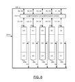
- the data D 1 -D 5 is split into multiple stripes to be sent to the drive interface 216 .
- the striped data is compressed by the compression engine sent to the drive interface.
- the actual data D 1 -Dn along with the compressed data C 1 -Cn is sent to the drive enclosure 300 .
- Data may be sent on a data channel 320 .
- Each of the drives 100 a - 100 n may receive data on the primary port P 1 from the data channel 320 .
- the data from the data channel 320 may be compressed by the compression/decompression engine 214 .
- Each of the drives 100 a - 100 n may receive compressed data on the secondary port P 2 from the compression/decompression engine 214 .
- This ensures that the RAID group works with any number of drives 100 a - 100 n without loss of drive performance.
- the present invention normally provides a fault-tolerance of 2n/3 drives, where n is the total number of drives in the RAID group provided that there are not three logically contiguous drive failures.
- the present invention may provide storage efficiency equal to RAID 1 with compression equal to 50%. Also, the present invention may provide performance and storage efficiency greater than RAID 1 with a compression greater than 50%. However, by implementing compression greater than 50%, the storage capacity efficiency of the drives 1001 - 100 n may be further improved.
- the present invention is generally more fault tolerant than the RAID 4, RAID 5 and RAID 6 implementations since the present invention may continue to operate without data loss if more than 2 drives fail (up to 2n/3 drives provided no 3 logically contiguous drives fail). Additional fault tolerance may be implemented compared with RAID 3, RAID 5 and RAID 6 groups.
- RAID 3, RAID 5 and RAID 6 groups whenever a modify operation is implemented on the group, all the drives need to be read to recalculate the parity and update the parity along with the modified data.
- the present invention for every modify operation, the data is striped and written to the respective drives 100 a - 100 n . The compression of the stripes are then independently generated and written onto the logically contiguous drives in the RAID group. Fewer reads and/or updates are needed compared with the parity generation methods.
- the drive system 150 may handle a multiple drive loss scenario, so long as all of the drives that fail are non-contiguous.
- the drive 100 a , the drive 100 b and the drive 100 d are marked with an X to show drive failures. Even with three drives failing, all the data will continue to be available.
- TABLE 1 describes the state of each drive and the data availability:
Abstract
Description
| TABLE 1 | |||
| Drive | | Data Availability | |
| 1 | Failed | Through C1 in |
|
| 2 | Failed | Through C2 in |
|
| 3 | Optimal | Through |
|
| 4 | Failed | Through C4 in |
|
| 5 | Optimal | Through D5 | |
Claims (20)
Priority Applications (6)
| Application Number | Priority Date | Filing Date | Title |
|---|---|---|---|
| US12/732,841 US8112663B2 (en) | 2010-03-26 | 2010-03-26 | Method to establish redundancy and fault tolerance better than RAID level 6 without using parity |
| TW100109844A TWI376683B (en) | 2010-03-26 | 2011-03-23 | Method for implementing fault tolerance in a drive array and storage device using said method |
| JP2011068012A JP4955822B2 (en) | 2010-03-26 | 2011-03-25 | Method for establishing redundancy and fault tolerance better than RAID level 6 without using parity |
| KR1020110027103A KR101162702B1 (en) | 2010-03-26 | 2011-03-25 | Method to establish redundancy and fault tolerance better than raid level 6 without using parity |
| EP11159720A EP2375332B1 (en) | 2010-03-26 | 2011-03-25 | Method to establish redundancy and fault tolerance better than raid level 6 without using parity |
| CN2011100760383A CN102200938B (en) | 2010-03-26 | 2011-03-28 | Method to establish redundancy and fault tolerance better than raid level 6 without using parity |
Applications Claiming Priority (1)
| Application Number | Priority Date | Filing Date | Title |
|---|---|---|---|
| US12/732,841 US8112663B2 (en) | 2010-03-26 | 2010-03-26 | Method to establish redundancy and fault tolerance better than RAID level 6 without using parity |
Publications (2)
| Publication Number | Publication Date |
|---|---|
| US20110239042A1 US20110239042A1 (en) | 2011-09-29 |
| US8112663B2 true US8112663B2 (en) | 2012-02-07 |
Family
ID=44527898
Family Applications (1)
| Application Number | Title | Priority Date | Filing Date |
|---|---|---|---|
| US12/732,841 Expired - Fee Related US8112663B2 (en) | 2010-03-26 | 2010-03-26 | Method to establish redundancy and fault tolerance better than RAID level 6 without using parity |
Country Status (6)
| Country | Link |
|---|---|
| US (1) | US8112663B2 (en) |
| EP (1) | EP2375332B1 (en) |
| JP (1) | JP4955822B2 (en) |
| KR (1) | KR101162702B1 (en) |
| CN (1) | CN102200938B (en) |
| TW (1) | TWI376683B (en) |
Cited By (3)
| Publication number | Priority date | Publication date | Assignee | Title |
|---|---|---|---|---|
| US20120303892A1 (en) * | 2011-05-23 | 2012-11-29 | International Business Machines Corporation | Writing of new data of a first block size in a raid array that stores both parity and data in a second block size |
| US20120303891A1 (en) * | 2011-05-23 | 2012-11-29 | International Business Machines Corporation | Writing of data of a first block size in a raid array that stores and mirrors data in a second block size |
| US10512680B2 (en) | 2012-12-28 | 2019-12-24 | Boehringer Ingelheim Vetmedica Gmbh | Method of making a mycoplasma vaccine |
Families Citing this family (3)
| Publication number | Priority date | Publication date | Assignee | Title |
|---|---|---|---|---|
| US8181062B2 (en) * | 2010-03-26 | 2012-05-15 | Lsi Corporation | Method to establish high level of redundancy, fault tolerance and performance in a raid system without using parity and mirroring |
| US11204716B2 (en) * | 2019-01-31 | 2021-12-21 | EMC IP Holding Company LLC | Compression offloading to RAID array storage enclosure |
| US11055188B2 (en) | 2019-04-12 | 2021-07-06 | EMC IP Holding Company LLC | Offloading error processing to raid array storage enclosure |
Citations (21)
| Publication number | Priority date | Publication date | Assignee | Title |
|---|---|---|---|---|
| US5757642A (en) | 1995-01-20 | 1998-05-26 | Dell Usa L.P. | Multi-function server input/output subsystem and method |
| US5812754A (en) | 1996-09-18 | 1998-09-22 | Silicon Graphics, Inc. | Raid system with fibre channel arbitrated loop |
| US6079029A (en) | 1997-03-17 | 2000-06-20 | Fujitsu Limited | Device array system providing redundancy of disks from active system disks during a disk failure |
| US6098128A (en) | 1995-09-18 | 2000-08-01 | Cyberstorage Systems Corporation | Universal storage management system |
| US6151659A (en) | 1997-12-22 | 2000-11-21 | Emc Corporation | Distributed raid storage system |
| US6170037B1 (en) * | 1997-09-02 | 2001-01-02 | Emc Corporation | Method and apparatus for storing information among a plurality of disk drives |
| US6192027B1 (en) | 1998-09-04 | 2001-02-20 | International Business Machines Corporation | Apparatus, system, and method for dual-active fibre channel loop resiliency during controller failure |
| US20020035669A1 (en) | 2000-09-19 | 2002-03-21 | Sung-Hoon Baek | Apparatus for redundant interconnection between multiple hosts and raid |
| US6442659B1 (en) | 1998-02-17 | 2002-08-27 | Emc Corporation | Raid-type storage system and technique |
| US20030041211A1 (en) * | 2001-03-07 | 2003-02-27 | Merkey Jeffrey Vernon | Dual axis RAID systems for enhanced bandwidth and reliability |
| US6678768B1 (en) | 2000-10-06 | 2004-01-13 | International Business Machines Corporation | Method and apparatus for configuring redundant array of independent disks (RAID) |
| US20040059869A1 (en) | 2002-09-20 | 2004-03-25 | Tim Orsley | Accelerated RAID with rewind capability |
| US20050039069A1 (en) * | 2003-04-03 | 2005-02-17 | Anand Prahlad | Remote disaster data recovery system and method |
| US20060077724A1 (en) * | 2004-10-12 | 2006-04-13 | Takashi Chikusa | Disk array system |
| US20060206640A1 (en) * | 2005-03-09 | 2006-09-14 | Tetsuya Abe | Storage apparatus |
| US7281160B2 (en) | 2003-02-10 | 2007-10-09 | Netezza Corporation | Rapid regeneration of failed disk sector in a distributed database system |
| US7512862B1 (en) | 2005-04-13 | 2009-03-31 | Network Appliance, Inc. | Compression of data for protection |
| US20090106492A1 (en) * | 2007-10-19 | 2009-04-23 | Hitachi, Ltd. | Storage apparatus and data storage method using the same |
| US7640452B2 (en) | 2006-07-28 | 2009-12-29 | Qnap Systems, Inc. | Method for reconstructing data in case of two disk drives of RAID failure and system therefor |
| US20100268857A1 (en) * | 2009-04-20 | 2010-10-21 | International Business Machines Corporation | Management of Redundant Physical Data Paths in a Computing System |
| US20100274926A1 (en) | 2009-04-22 | 2010-10-28 | Rajendra Sadanand Marulkar | High-speed inline data compression inline with an eight byte data path |
Family Cites Families (2)
| Publication number | Priority date | Publication date | Assignee | Title |
|---|---|---|---|---|
| US7584378B2 (en) * | 2006-09-07 | 2009-09-01 | International Business Machines Corporation | Reconfigurable FC-AL storage loops in a data storage system |
| JP2009193125A (en) * | 2008-02-12 | 2009-08-27 | Hitachi Ltd | Storage system for managing encryption key, computer system and method |
-
2010
- 2010-03-26 US US12/732,841 patent/US8112663B2/en not_active Expired - Fee Related
-
2011
- 2011-03-23 TW TW100109844A patent/TWI376683B/en not_active IP Right Cessation
- 2011-03-25 JP JP2011068012A patent/JP4955822B2/en not_active Expired - Fee Related
- 2011-03-25 EP EP11159720A patent/EP2375332B1/en not_active Not-in-force
- 2011-03-25 KR KR1020110027103A patent/KR101162702B1/en not_active IP Right Cessation
- 2011-03-28 CN CN2011100760383A patent/CN102200938B/en not_active Expired - Fee Related
Patent Citations (23)
| Publication number | Priority date | Publication date | Assignee | Title |
|---|---|---|---|---|
| US5757642A (en) | 1995-01-20 | 1998-05-26 | Dell Usa L.P. | Multi-function server input/output subsystem and method |
| US6098128A (en) | 1995-09-18 | 2000-08-01 | Cyberstorage Systems Corporation | Universal storage management system |
| US5812754A (en) | 1996-09-18 | 1998-09-22 | Silicon Graphics, Inc. | Raid system with fibre channel arbitrated loop |
| US6079029A (en) | 1997-03-17 | 2000-06-20 | Fujitsu Limited | Device array system providing redundancy of disks from active system disks during a disk failure |
| US6170037B1 (en) * | 1997-09-02 | 2001-01-02 | Emc Corporation | Method and apparatus for storing information among a plurality of disk drives |
| US6151659A (en) | 1997-12-22 | 2000-11-21 | Emc Corporation | Distributed raid storage system |
| US6442659B1 (en) | 1998-02-17 | 2002-08-27 | Emc Corporation | Raid-type storage system and technique |
| US6192027B1 (en) | 1998-09-04 | 2001-02-20 | International Business Machines Corporation | Apparatus, system, and method for dual-active fibre channel loop resiliency during controller failure |
| US20020035669A1 (en) | 2000-09-19 | 2002-03-21 | Sung-Hoon Baek | Apparatus for redundant interconnection between multiple hosts and raid |
| US6978346B2 (en) | 2000-09-19 | 2005-12-20 | Electronics And Telecommunications Reseach Institute | Apparatus for redundant interconnection between multiple hosts and raid |
| US6678768B1 (en) | 2000-10-06 | 2004-01-13 | International Business Machines Corporation | Method and apparatus for configuring redundant array of independent disks (RAID) |
| US6795895B2 (en) | 2001-03-07 | 2004-09-21 | Canopy Group | Dual axis RAID systems for enhanced bandwidth and reliability |
| US20030041211A1 (en) * | 2001-03-07 | 2003-02-27 | Merkey Jeffrey Vernon | Dual axis RAID systems for enhanced bandwidth and reliability |
| US20040059869A1 (en) | 2002-09-20 | 2004-03-25 | Tim Orsley | Accelerated RAID with rewind capability |
| US7281160B2 (en) | 2003-02-10 | 2007-10-09 | Netezza Corporation | Rapid regeneration of failed disk sector in a distributed database system |
| US20050039069A1 (en) * | 2003-04-03 | 2005-02-17 | Anand Prahlad | Remote disaster data recovery system and method |
| US20060077724A1 (en) * | 2004-10-12 | 2006-04-13 | Takashi Chikusa | Disk array system |
| US20060206640A1 (en) * | 2005-03-09 | 2006-09-14 | Tetsuya Abe | Storage apparatus |
| US7512862B1 (en) | 2005-04-13 | 2009-03-31 | Network Appliance, Inc. | Compression of data for protection |
| US7640452B2 (en) | 2006-07-28 | 2009-12-29 | Qnap Systems, Inc. | Method for reconstructing data in case of two disk drives of RAID failure and system therefor |
| US20090106492A1 (en) * | 2007-10-19 | 2009-04-23 | Hitachi, Ltd. | Storage apparatus and data storage method using the same |
| US20100268857A1 (en) * | 2009-04-20 | 2010-10-21 | International Business Machines Corporation | Management of Redundant Physical Data Paths in a Computing System |
| US20100274926A1 (en) | 2009-04-22 | 2010-10-28 | Rajendra Sadanand Marulkar | High-speed inline data compression inline with an eight byte data path |
Cited By (9)
| Publication number | Priority date | Publication date | Assignee | Title |
|---|---|---|---|---|
| US20120303892A1 (en) * | 2011-05-23 | 2012-11-29 | International Business Machines Corporation | Writing of new data of a first block size in a raid array that stores both parity and data in a second block size |
| US20120303890A1 (en) * | 2011-05-23 | 2012-11-29 | International Business Machines Corporation | Writing of new data of a first block size in a raid array that stores both parity and data in a second block size |
| US20120303891A1 (en) * | 2011-05-23 | 2012-11-29 | International Business Machines Corporation | Writing of data of a first block size in a raid array that stores and mirrors data in a second block size |
| US20120303893A1 (en) * | 2011-05-23 | 2012-11-29 | International Business Machines Corporation | Writing of data of a first block size in a raid array that stores and mirrors data in a second block size |
| US8949528B2 (en) * | 2011-05-23 | 2015-02-03 | International Business Machines Corporation | Writing of data of a first block size in a raid array that stores and mirrors data in a second block size |
| US8954668B2 (en) * | 2011-05-23 | 2015-02-10 | International Business Machines Corporation | Writing of data of a first block size in a raid array that stores and mirrors data in a second block size |
| US9043544B2 (en) * | 2011-05-23 | 2015-05-26 | International Business Machines Corporation | Writing of new data of a first block size in a raid array that stores both parity and data in a second block size |
| US9043543B2 (en) * | 2011-05-23 | 2015-05-26 | International Business Machines Corporation | Writing of new data of a first block size in a raid array that stores both parity and data in a second block size |
| US10512680B2 (en) | 2012-12-28 | 2019-12-24 | Boehringer Ingelheim Vetmedica Gmbh | Method of making a mycoplasma vaccine |
Also Published As
| Publication number | Publication date |
|---|---|
| JP4955822B2 (en) | 2012-06-20 |
| TW201203227A (en) | 2012-01-16 |
| JP2011243189A (en) | 2011-12-01 |
| TWI376683B (en) | 2012-11-11 |
| US20110239042A1 (en) | 2011-09-29 |
| EP2375332A2 (en) | 2011-10-12 |
| KR101162702B1 (en) | 2012-07-05 |
| CN102200938A (en) | 2011-09-28 |
| EP2375332A3 (en) | 2011-10-26 |
| EP2375332B1 (en) | 2012-10-31 |
| KR20110108312A (en) | 2011-10-05 |
| CN102200938B (en) | 2013-12-04 |
Similar Documents
| Publication | Publication Date | Title |
|---|---|---|
| JP4516846B2 (en) | Disk array system | |
| US8112663B2 (en) | Method to establish redundancy and fault tolerance better than RAID level 6 without using parity | |
| US8327080B1 (en) | Write-back cache protection | |
| US7386757B2 (en) | Method and apparatus for enabling high-reliability storage of distributed data on a plurality of independent storage devices | |
| KR100275900B1 (en) | Method for implement divideo parity spare disk in raid sub-system | |
| US7979779B1 (en) | System and method for symmetric triple parity for failing storage devices | |
| US7673167B2 (en) | RAID array data member copy offload in high density packaging | |
| US9639457B1 (en) | Data storage system and method for data migration between high-performance computing architectures and data storage devices using storage controller with distributed XOR capability | |
| TWI391815B (en) | Enclosure-based raid parity assist | |
| JPH10260789A (en) | Device array system | |
| US8181062B2 (en) | Method to establish high level of redundancy, fault tolerance and performance in a raid system without using parity and mirroring | |
| JP2010503941A (en) | Optimized method to restore and copy back a disconnected drive when there is a global hot spare disk | |
| US20230205632A1 (en) | Reliability coding with reduced network traffic | |
| Reddy et al. | Gracefully degradable disk arrays | |
| JP5360666B2 (en) | Method and system for performing I / O operations of multiple disk arrays | |
| JP2000148409A (en) | Redundant storage device | |
| JP2006285802A (en) | Data storage device, reconstruction control device, reconstruction control method, program and storage medium | |
| JP2010224803A (en) | Disk array device | |
| JPH0816327A (en) | Disk array device | |
| Terao | Technologies of ETERNUS 6000 and ETERNUS 3000 Mission-Critical Disk Arrays | |
| JPH10240452A (en) | Distributed data storage system and recovery system |
Legal Events
| Date | Code | Title | Description |
|---|---|---|---|
| AS | Assignment |
Owner name: LSI CORPORATION, CALIFORNIA Free format text: ASSIGNMENT OF ASSIGNORS INTEREST;ASSIGNORS:P S, PAVAN;PRAKASH, VIVEK;JIBBE, MAHMOUD K.;SIGNING DATES FROM 20100325 TO 20100326;REEL/FRAME:024147/0112 |
|
| STCF | Information on status: patent grant |
Free format text: PATENTED CASE |
|
| AS | Assignment |
Owner name: DEUTSCHE BANK AG NEW YORK BRANCH, AS COLLATERAL AG Free format text: PATENT SECURITY AGREEMENT;ASSIGNORS:LSI CORPORATION;AGERE SYSTEMS LLC;REEL/FRAME:032856/0031 Effective date: 20140506 |
|
| AS | Assignment |
Owner name: AVAGO TECHNOLOGIES GENERAL IP (SINGAPORE) PTE. LTD Free format text: ASSIGNMENT OF ASSIGNORS INTEREST;ASSIGNOR:LSI CORPORATION;REEL/FRAME:035390/0388 Effective date: 20140814 |
|
| FPAY | Fee payment |
Year of fee payment: 4 |
|
| AS | Assignment |
Owner name: AGERE SYSTEMS LLC, PENNSYLVANIA Free format text: TERMINATION AND RELEASE OF SECURITY INTEREST IN PATENT RIGHTS (RELEASES RF 032856-0031);ASSIGNOR:DEUTSCHE BANK AG NEW YORK BRANCH, AS COLLATERAL AGENT;REEL/FRAME:037684/0039 Effective date: 20160201 Owner name: LSI CORPORATION, CALIFORNIA Free format text: TERMINATION AND RELEASE OF SECURITY INTEREST IN PATENT RIGHTS (RELEASES RF 032856-0031);ASSIGNOR:DEUTSCHE BANK AG NEW YORK BRANCH, AS COLLATERAL AGENT;REEL/FRAME:037684/0039 Effective date: 20160201 |
|
| AS | Assignment |
Owner name: BANK OF AMERICA, N.A., AS COLLATERAL AGENT, NORTH CAROLINA Free format text: PATENT SECURITY AGREEMENT;ASSIGNOR:AVAGO TECHNOLOGIES GENERAL IP (SINGAPORE) PTE. LTD.;REEL/FRAME:037808/0001 Effective date: 20160201 Owner name: BANK OF AMERICA, N.A., AS COLLATERAL AGENT, NORTH Free format text: PATENT SECURITY AGREEMENT;ASSIGNOR:AVAGO TECHNOLOGIES GENERAL IP (SINGAPORE) PTE. LTD.;REEL/FRAME:037808/0001 Effective date: 20160201 |
|
| AS | Assignment |
Owner name: AVAGO TECHNOLOGIES GENERAL IP (SINGAPORE) PTE. LTD., SINGAPORE Free format text: TERMINATION AND RELEASE OF SECURITY INTEREST IN PATENTS;ASSIGNOR:BANK OF AMERICA, N.A., AS COLLATERAL AGENT;REEL/FRAME:041710/0001 Effective date: 20170119 Owner name: AVAGO TECHNOLOGIES GENERAL IP (SINGAPORE) PTE. LTD Free format text: TERMINATION AND RELEASE OF SECURITY INTEREST IN PATENTS;ASSIGNOR:BANK OF AMERICA, N.A., AS COLLATERAL AGENT;REEL/FRAME:041710/0001 Effective date: 20170119 |
|
| AS | Assignment |
Owner name: AVAGO TECHNOLOGIES INTERNATIONAL SALES PTE. LIMITE Free format text: MERGER;ASSIGNOR:AVAGO TECHNOLOGIES GENERAL IP (SINGAPORE) PTE. LTD.;REEL/FRAME:047230/0133 Effective date: 20180509 |
|
| AS | Assignment |
Owner name: AVAGO TECHNOLOGIES INTERNATIONAL SALES PTE. LIMITE Free format text: CORRECTIVE ASSIGNMENT TO CORRECT THE EFFECTIVE DATE OF MERGER TO 09/05/2018 PREVIOUSLY RECORDED AT REEL: 047230 FRAME: 0133. ASSIGNOR(S) HEREBY CONFIRMS THE MERGER;ASSIGNOR:AVAGO TECHNOLOGIES GENERAL IP (SINGAPORE) PTE. LTD.;REEL/FRAME:047630/0456 Effective date: 20180905 |
|
| FEPP | Fee payment procedure |
Free format text: MAINTENANCE FEE REMINDER MAILED (ORIGINAL EVENT CODE: REM.); ENTITY STATUS OF PATENT OWNER: LARGE ENTITY |
|
| LAPS | Lapse for failure to pay maintenance fees |
Free format text: PATENT EXPIRED FOR FAILURE TO PAY MAINTENANCE FEES (ORIGINAL EVENT CODE: EXP.); ENTITY STATUS OF PATENT OWNER: LARGE ENTITY |
|
| STCH | Information on status: patent discontinuation |
Free format text: PATENT EXPIRED DUE TO NONPAYMENT OF MAINTENANCE FEES UNDER 37 CFR 1.362 |
|
| FP | Lapsed due to failure to pay maintenance fee |
Effective date: 20200207 |