US8089339B2 - Wireless device as programmable vehicle key - Google Patents
Wireless device as programmable vehicle key Download PDFInfo
- Publication number
- US8089339B2 US8089339B2 US11/614,434 US61443406A US8089339B2 US 8089339 B2 US8089339 B2 US 8089339B2 US 61443406 A US61443406 A US 61443406A US 8089339 B2 US8089339 B2 US 8089339B2
- Authority
- US
- United States
- Prior art keywords
- vehicle
- database
- key
- network
- access control
- Prior art date
- Legal status (The legal status is an assumption and is not a legal conclusion. Google has not performed a legal analysis and makes no representation as to the accuracy of the status listed.)
- Active, expires
Links
Images


Classifications
-
- G—PHYSICS
- G07—CHECKING-DEVICES
- G07C—TIME OR ATTENDANCE REGISTERS; REGISTERING OR INDICATING THE WORKING OF MACHINES; GENERATING RANDOM NUMBERS; VOTING OR LOTTERY APPARATUS; ARRANGEMENTS, SYSTEMS OR APPARATUS FOR CHECKING NOT PROVIDED FOR ELSEWHERE
- G07C9/00—Individual registration on entry or exit
- G07C9/00174—Electronically operated locks; Circuits therefor; Nonmechanical keys therefor, e.g. passive or active electrical keys or other data carriers without mechanical keys
- G07C9/00309—Electronically operated locks; Circuits therefor; Nonmechanical keys therefor, e.g. passive or active electrical keys or other data carriers without mechanical keys operated with bidirectional data transmission between data carrier and locks
-
- H—ELECTRICITY
- H04—ELECTRIC COMMUNICATION TECHNIQUE
- H04L—TRANSMISSION OF DIGITAL INFORMATION, e.g. TELEGRAPHIC COMMUNICATION
- H04L63/00—Network architectures or network communication protocols for network security
- H04L63/08—Network architectures or network communication protocols for network security for authentication of entities
- H04L63/0853—Network architectures or network communication protocols for network security for authentication of entities using an additional device, e.g. smartcard, SIM or a different communication terminal
-
- G—PHYSICS
- G07—CHECKING-DEVICES
- G07C—TIME OR ATTENDANCE REGISTERS; REGISTERING OR INDICATING THE WORKING OF MACHINES; GENERATING RANDOM NUMBERS; VOTING OR LOTTERY APPARATUS; ARRANGEMENTS, SYSTEMS OR APPARATUS FOR CHECKING NOT PROVIDED FOR ELSEWHERE
- G07C9/00—Individual registration on entry or exit
- G07C9/00174—Electronically operated locks; Circuits therefor; Nonmechanical keys therefor, e.g. passive or active electrical keys or other data carriers without mechanical keys
- G07C9/00309—Electronically operated locks; Circuits therefor; Nonmechanical keys therefor, e.g. passive or active electrical keys or other data carriers without mechanical keys operated with bidirectional data transmission between data carrier and locks
- G07C2009/00507—Electronically operated locks; Circuits therefor; Nonmechanical keys therefor, e.g. passive or active electrical keys or other data carriers without mechanical keys operated with bidirectional data transmission between data carrier and locks keyless data carrier having more than one function
-
- H—ELECTRICITY
- H04—ELECTRIC COMMUNICATION TECHNIQUE
- H04L—TRANSMISSION OF DIGITAL INFORMATION, e.g. TELEGRAPHIC COMMUNICATION
- H04L67/00—Network arrangements or protocols for supporting network services or applications
- H04L67/01—Protocols
- H04L67/12—Protocols specially adapted for proprietary or special-purpose networking environments, e.g. medical networks, sensor networks, networks in vehicles or remote metering networks
Definitions
- Automobiles and other vehicles are often secured from unauthorized access and operation via lock and key. Once locked, the vehicle's doors and ignition system remain inoperable until the proper key is used. Keys traditionally have been made of metal blanks with grooves and teeth shaped to engage the lock. Electronic keys may provide similar functionality as their metal key counterparts. In addition, an electronic key may not require the operator of the vehicle to physically place the key within the lock. For example, the electronic key may operate via a proximity sensor within the car. When the electronic key is within range of the proximity sensor, the vehicle may shift from an inoperable, “locked” mode to an operable mode.
- valet key In addition to metal and electronic keys that grant full access to open and operate a vehicle, some vehicle manufactures provide a “valet key” that grants limited access to the vehicle.
- the valet key is typically a metal key that allows the holder to unlock the driver's side door and operate the ignition lock.
- the valet key typically does not provide access to the vehicle's trunk, glove box, or other secure areas of the vehicle. With respect to the operation of the vehicle, however, the valet key does not limit the range or manner in which the holder operates the vehicle.
- the holder of a valet key may operate the vehicle at any speed or over any distance, which may not be acceptable for the vehicle's owner.
- conventional metal and electronic keys typically provide the owner with only two options.
- the first option is to provide the person with a “regular” key that provides the person with full access to all of the vehicle's features.
- the second option is to provide the person with a valet key that restricts the person's access to certain vehicle compartments. In either case, the owner has no way to restrict the person's ability to operate the vehicle.
- Wireless devices such as cellular telephones, are increasingly ubiquitous. They are increasingly able to process applications and perform digital functions beyond placing and receiving telephone calls. Their network connectivity gives them functionality typically not found in other handheld devices.
- the method includes detecting a key for accessing a vehicle, retrieving a vehicle operation policy associated with the key, and permitting operation of the vehicle consistent with the vehicle operation policy.
- the key may be embedded within a wireless device such as a cellular telephone.
- the vehicle operation policy may include an access control rule that may indicate to enable, partially enable, or disable a vehicle operation feature. Where the intended operation of the vehicle is not consistent with the access control rule, the operation may not be permitted and an enforcement action may be taken, such as disabling a feature of the vehicle for example.
- Records in a first database may be synchronized with records in a second database.
- the second database may reside in a vehicle and the first database may communicate with the second database via a wireless network.
- the records may include an access control rule.
- the wireless device may include a user interface module, a wireless communications module, a memory, a processor, and a vehicle access module.
- the wireless communications module may communicate an request to update an access control rule via the wireless network.
- the vehicle access module may communicate a secure identifier to access the vehicle.
- FIG. 1A depicts an overview of a network environment in which aspects of an embodiment may be implemented
- FIG. 1B depicts a GPRS network architecture in which aspects of an embodiment may be implemented
- FIG. 1C depicts an alternate block diagram of an example GSM/GPRS/IP multimedia network architecture in which aspects of an embodiment may be implemented
- FIG. 2 depicts a block diagram of an example wireless vehicle security system
- FIGS. 3A-B depicts a block diagram of an example master database and local database, respectively;
- FIG. 4 depicts a block diagram of an example wireless device equipped for use as an electronic key
- FIG. 5 depicts a flow diagram of an example vehicle security process
- FIG. 6 depicts a flow diagram of an example network security process.
- the following description sets forth some example telephony radio networks and non-limiting operating environments in which a wireless vehicle security system according to an embodiment may be used.
- the below-described operating environments should be considered non-exhaustive, however, and thus the below-described network architecture merely shows an example network architecture in which aspects of various embodiments may be incorporated.
- GSM Global System for mobile communication
- GSM Global System for mobile communication
- GPRS General Packet Radio Service
- GPRS uses a packet-based wireless communication technology to transfer high and low speed data and signaling in an efficient manner.
- GPRS optimizes the use of network and radio resources, thus enabling the cost effective and efficient use of GSM network resources for packet mode applications.
- various embodiments are described herein in connection with GSM.
- the references to GSM are not exclusive, however, as it should be appreciated that embodiments may be implemented in connection with any type of wireless access system such as, for example, CDMA or the like.
- the example GSM/GPRS environment and services described herein can also be extended to 3G services, such as Universal Mobile Telephone System (“UMTS”), Frequency Division Duplexing (“FDD”) and Time Division Duplexing (“TDD”), High Speed Packet Data Access (“HSPDA”), cdma2000 1 ⁇ Evolution Data Optimized (“EVDO”), Code Division Multiple Access-2000 (“cdma2000 3 ⁇ ”), Time Division Synchronous Code Division Multiple Access (“TD-SCDMA”), Wideband Code Division Multiple Access (“WCDMA”), Enhanced Data GSM Environment (“EDGE”), International Mobile Telecommunications-2000 (“IMT-2000”), Digital Enhanced Cordless Telecommunications (“DECT”), etc., as well as to other network services that shall become available in time.
- UMTS Universal Mobile Telephone System
- FDD Frequency Division Duplexing
- TDD Time Division Duplexing
- HSPDA High Speed Packet Data Access
- EVDO cdma2000 1 ⁇ Evolution Data Optimized
- TD-SCDMA Time
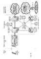
- FIG. 1A depicts an overall block diagram of an example packet-based mobile cellular network environment, such as a GPRS network, in which aspects of an embodiment may be practiced.
- a plurality of Base Station Subsystems (“BSS”) 100 each of which comprises a Base Station Controller (“BSC”) 104 serving a plurality of Base Transceiver Stations (“BTS”) such as, for example, BTSs 101 , 102 and 103 .
- BTSs 101 , 102 , 103 , etc. are the access points where users of packet-based mobile devices become connected to the wireless network.
- the packet traffic originating from user devices is transported over the air interface to BTS 103 , and from BTS 103 to BSC 104 .
- Base station subsystems such as BSS 100 , may be a part of internal frame relay network 106 that may include Service GPRS Support Nodes (“SGSN”) such as SGSN 105 and 107 .
- SGSN Service GPRS Support Nodes
- Each SGSN 105 , 107 , etc. may be in turn connected to internal packet network 108 through which SGSN 105 , 107 , etc. can route data packets to and from a plurality of gateway GPRS support nodes (GGSN) 222 , 111 , 110 , etc.
- GGSN gateway GPRS support nodes
- Gateway GPRS serving nodes 222 , 111 and 110 may provide an interface to external Internet Protocol (“IP”) networks such as Public Land Mobile Network (“PLMN”) 115 , corporate intranets 117 , Fixed-End System (“FES”), the public Internet 113 or the like.
- IP Internet Protocol
- PLMN Public Land Mobile Network
- FES Fixed-End System
- subscriber corporate network 117 may be connected to GGSN 111 via firewall 112 ; and PLMN 115 may be connected to GGSN 111 via boarder gateway router 114 .
- Remote Authentication Dial-In User Service (“RADIUS”) server 116 may be used for caller authentication when a user of a mobile cellular device calls corporate network 117 , for example.
- Macro cells may be regarded as cells where the base station antenna is installed in a mast or a building above average roof top level.
- Micro cells are cells whose antenna height is under average roof top level; they are typically used in urban areas.
- Pico cells are small cells having a diameter is a few dozen meters; they are mainly used indoors.
- umbrella cells are used to cover shadowed regions of smaller cells and fill in gaps in coverage between those cells.
- FIG. 1B illustrates the architecture of a typical GPRS network as segmented into four groups: users 115 , radio access network 120 , core network 124 and interconnect network 137 .
- Users 115 comprise a plurality of end users.
- Radio access network 120 comprises a plurality of base station subsystems such as BSSs 123 , which include BTSs 121 and BSCs 122 .
- Core network 124 comprises a host of various network elements.
- core network 124 may comprise Mobile Switching Center (“MSC”) 125 , Service Control Point (“SCP”) 126 , gateway MSC 127 , SGSN 130 , Home Location Register (“HLR”) 129 , Authentication Center (“AuC”) 128 , Domain Name Server (“DNS”) 131 and GGSN 132 .
- Interconnect network 137 also comprises a host of various networks and other network elements. As illustrated in FIG. 1B , interconnect network 137 comprises Public Switched Telephone Network (“PSTN”) 133 , Fixed-End System (“FES”) or Internet 134 , firewall 135 and Corporate Network 136 .
- PSTN Public Switched Telephone Network
- FES Fixed-End System
- firewall 135 and Corporate Network 136 .
- a mobile switching center 125 may be connected to a large number of base station controllers.
- the traffic may be separated such that voice may be sent to Public Switched Telephone Network (“PSTN”) 133 through Gateway MSC (“GMSC”) 127 , and/or data may be sent to SGSN 130 , which then sends the data traffic to GGSN 132 for further forwarding.
- PSTN Public Switched Telephone Network
- GMSC Gateway MSC
- MSC 125 When MSC 125 receives call traffic, for example, from BSC 122 , it may send a query to a database hosted by SCP 126 . The SCP 126 processes the request and issues a response to MSC 125 so that it may continue call processing as appropriate.
- HLR 129 is a centralized database for users to register to the GPRS network.
- HLR 129 stores static information about the subscribers such as the International Mobile Subscriber Identity (“IMSI”), subscribed services, and a key for authenticating the subscriber.
- IMSI International Mobile Subscriber Identity
- HLR 129 also stores dynamic subscriber information such as the current location of the mobile subscriber.
- AuC 128 is a database that contains the algorithms for authenticating subscribers and includes the associated keys for encryption to safeguard the user input for authentication.
- the term “mobile subscriber” may refer to either the end user or to the actual portable device used by an end user of the mobile cellular service.
- the mobile device goes through an attach process by which the mobile device attaches to an SGSN of the GPRS network.
- an attach request is sent by mobile subscriber 119 to SGSN 130 .
- the SGSN 130 queries another SGSN, to which mobile subscriber 119 was attached before, for the identity of mobile subscriber 119 .
- SGSN 130 Upon receiving the identity of mobile subscriber 119 from the other SGSN, SGSN 130 requests more information from mobile subscriber 119 . This information is used to authenticate mobile subscriber 119 to SGSN 130 by HLR 129 . Once verified, SGSN 130 sends a location update to HLR 129 indicating the change of location to a new SGSN, in this case SGSN 130 . HLR 129 notifies the old SGSN, to which mobile subscriber 119 was attached, to cancel the location process for mobile subscriber 119 . HLR 129 then notifies SGSN 130 that the location update has been performed. At this time, SGSN 130 sends an Attach Accept message to mobile subscriber 119 , which in turn sends an Attach Complete message to SGSN 130 .
- mobile subscriber 119 After attaching itself with the network, mobile subscriber 119 then goes through the authentication process. In the authentication process, SGSN 130 sends the authentication information to HLR 129 , which sends information back to SGSN 130 based on the user profile that was part of the user's initial setup. SGSN 130 then sends a request for authentication and ciphering to mobile subscriber 119 . Mobile subscriber 119 uses an algorithm to send the user identification (ID) and password to SGSN 130 . SGSN 130 uses the same algorithm and compares the result. If a match occurs, SGSN 130 authenticates mobile subscriber 119 .
- ID user identification
- SGSN 130 uses the same algorithm and compares the result. If a match occurs, SGSN 130 authenticates mobile subscriber 119 .
- mobile subscriber 119 establishes a user session with the destination network, corporate network 136 , by going through a Packet Data Protocol (“PDP”) activation process.
- PDP Packet Data Protocol
- mobile subscriber 119 requests access to the Access Point Name (“APN”), for example, UPS.com (e.g., which can be corporate network 279 ) and SGSN 130 receives the activation request from mobile subscriber 119 .
- APN Access Point Name
- SGSN 130 then initiates a Domain Name Service (“DNS”) query to learn which GGSN node has access to the UPS.com APN.
- DNS Domain Name Service
- the DNS query is sent to the DNS server within the core network 124 , such as DNS 131 , which is provisioned to map to one or more GGSN nodes in the core network 124 .
- the mapped GGSN 132 can access the requested corporate network 279 .
- the SGSN 130 then sends to GGSN 132 a Create Packet Data Protocol (“PDP”) Context Request message that contains necessary information.
- PDP Packet Data Protocol
- the GGSN 132 sends a Create PDP Context Response message to SGSN 130 , which then sends an Activate PDP Context Accept message to mobile subscriber 119 .
- data packets of the call made by mobile subscriber 119 can then go through radio access network 120 , core network 124 , and interconnect network 137 , in particular fixed-end system or Internet 134 and firewall 135 , to reach corporate network 136 .
- FIG. 1C shows another example block diagram view of a GSM/GPRS/IP multimedia network architecture 138 in which the apparatus and methods for transferring multimedia content between receiving devices of the below-discussed embodiments may be incorporated.
- architecture 138 of FIG. 1C includes GSM core network 154 , GPRS network 157 and IP multimedia network 159 .
- GSM core network 154 includes Mobile Station (MS) 140 , at least one Base Transceiver Station (BTS) 141 and Base Station Controller (BSC) 142 .
- MS 140 is physical equipment or Mobile Equipment (ME), such as a mobile phone or a laptop computer that is used by mobile subscribers, with a Subscriber identity Module (SIM).
- ME Mobile Equipment
- the SIM includes an International Mobile Subscriber Identity (IMSI), which is a unique identifier of a subscriber.
- IMSI International Mobile Subscriber Identity
- BTS 141 is physical equipment, such as a radio tower, that enables a radio interface to communicate with the MS. Each BTS may serve more than one MS.
- BSC 142 manages radio resources, including the BTS. The BSC may be connected to several BTSs.
- the BSC and BTS components, in combination, are generally referred to as a base station (BSS) or radio access network (RAN) 143 .
- BSS base station
- RAN radio access network
- GSM core network 154 also includes Mobile Switching Center (MSC) 144 , Gateway Mobile Switching Center (GMSC) 145 , Home Location Register (HLR) 146 , Visitor Location Register (VLR) 147 , Authentication Center (AuC) 149 and Equipment Identity Register (EIR) 148 .
- MSC 144 performs a switching function for the network. The MSC also performs other functions, such as registration, authentication, location updating, handovers and call routing.
- GMSC 145 provides a gateway between the GSM network and other networks, such as an Integrated Services Digital Network (ISDN) or Public Switched Telephone Networks (PSTNs) 150 . In other words, GMSC 145 provides interworking functionality with external networks.
- ISDN Integrated Services Digital Network
- PSTNs Public Switched Telephone Networks
- HLR 146 is a database that contains administrative information regarding each subscriber registered in a corresponding GSM network. HLR 146 also contains the current location of each MS.
- VLR 147 is a database that contains selected administrative information from HLR 146 . The VLR contains information necessary for call control and provision of subscribed services for each MS currently located in a geographical area controlled by the VLR. HLR 146 and VLR 147 , together with MSC 144 , provide the call routing and roaming capabilities of GSM.
- AuC 148 provides the parameters needed for authentication and encryption functions. Such parameters allow verification of a subscriber's identity.
- EIR 149 stores security-sensitive information about the mobile equipment.
- SMS Short Message Service Center
- PPG Push Proxy Gateway
- SMS Short Message Service
- PPG Push Proxy Gateway
- SMS Short Message Service
- PPG Push Proxy Gateway
- SMS Short Message Service
- PPG Push Proxy Gateway
- PPG 152 acts as a proxy between wired and wireless networks to facilitate pushing of data to MS 140 .
- SMSPP Short Message Peer to Peer
- SMPP Short Message Peer to Peer
- SMPP Short Message Peer to Peer
- SMPP Short Message Peer to Peer
- SMPP Short Message Peer to Peer
- SMPP Short Message Peer to Peer
- SMPP Short Message Peer to Peer
- SMPP Short Message Peer to Peer
- SMPP Short Message Peer to Peer
- SMPP Short Message Peer to Peer
- SMPP Short Message Peer to Peer
- SMPP Short Message Peer to Peer
- SMPP Short Message Peer to Pe
- the MS To gain access to GSM services, such as speech, data, and short message service (SMS), the MS first registers with the network to indicate its current location by performing a location update and IMSI attach procedure.
- MS 140 sends a location update including its current location information to the MSC/VLR, via BTS 141 and BSC 142 .
- the location information is then sent to the MS's HLR.
- the HLR is updated with the location information received from the MSC/VLR.
- the location update also is performed when the MS moves to a new location area.
- the location update is periodically performed to update the database as location updating events occur.
- GPRS network 157 is logically implemented on the GSM core network architecture by introducing two packet-switching network nodes, a serving GPRS support node (SGSN) 155 and a cell broadcast and a Gateway GPRS support node (GGSN) 156 .
- SGSN 155 is at the same hierarchical level as MSC 144 in the GSM network.
- the SGSN controls the connection between the GPRS network and MS 140 .
- the SGSN also keeps track of individual MS's locations and security functions and access controls.
- Cell Broadcast Center (CBC) 171 communicates cell broadcast messages that are typically delivered to multiple users in a specified area.
- Cell Broadcast is one-to-many geographically focused service. It enables messages to be communicated to multiple mobile phone customers who are located within a given part of its network coverage area at the time the message is broadcast.
- GGSN 156 provides a gateway between the GPRS network and a public packet network (PDN) or other IP networks 158 . That is, the GGSN provides interworking functionality with external networks, and sets up a logical link to the MS through the SGSN. When packet-switched data leaves the GPRS network, it is transferred to external TCP-IP network 158 , such as an X.25 network or the Internet.
- PDN public packet network
- IP networks 158 such as an X.25 network or the Internet.
- the MS In order to access GPRS services, the MS first attaches itself to the GPRS network by performing an attach procedure. The MS then activates a packet data protocol (PDP) context, thus activating a packet communication session between the MS, the SGSN, and the GGSN.
- PDP packet data protocol
- GPRS services and GSM services can be used in parallel.
- the MS can operate in one three classes: class A, class B, and class C.
- class A MS can attach to the network for both GPRS services and GSM services simultaneously.
- class A MS also supports simultaneous operation of GPRS services and GSM services. For example, class A mobiles can receive GSM voice/data/SMS calls and GPRS data calls at the same time.
- a class B MS can attach to the network for both GPRS services and GSM services simultaneously. However, a class B MS does not support simultaneous operation of the GPRS services and GSM services. That is, a class B MS can only use one of the two services at a given time.
- a class C MS can attach for only one of the GPRS services and GSM services at a time. Simultaneous attachment and operation of GPRS services and GSM services is not possible with a class C MS.
- GPRS network 157 can be designed to operate in three network operation modes (NOM 1 , NOM 2 and NOM 3 ).
- a network operation mode of a GPRS network is indicated by a parameter in system information messages transmitted within a cell.
- the system information messages dictates a MS where to listen for paging messages and how signal towards the network.
- the network operation mode represents the capabilities of the GPRS network.
- NOM 1 a MS can receive pages from a circuit switched domain (voice call) when engaged in a data call. The MS can suspend the data call or take both simultaneously, depending on the ability of the MS.
- a MS may not received pages from a circuit switched domain when engaged in a data call, since the MS is receiving data and is not listening to a paging channel
- a MS can monitor pages for a circuit switched network while received data and vise versa.
- IP multimedia network 159 was introduced with 3GPP Release 5, and includes IP multimedia subsystem (IMS) 160 to provide rich multimedia services to end users.
- IMS 160 IP multimedia subsystem
- a representative set of the network entities within IMS 160 are a call/session control function (CSCF), media gateway control function (MGCF) 162 , media gateway (MGW) 165 , and a master subscriber database, referred to as a home subscriber server (HSS) 168 .
- HSS 168 may be common to GSM network 154 , GPRS network 157 as well as IP multimedia network 159 .
- IP multimedia system 160 is built around the call/session control function, of which there are three types: interrogating CSCF (I-CSCF) 164 , proxy CSCF (P-CSCF) 161 and serving CSCF (S-CSCF) 163 .
- P-CSCF 161 is the MS's first point of contact with IMS 160 .
- P-CSCF 161 forwards session initiation protocol (SIP) messages received from the MS to an SIP server in a home network (and vice versa) of the MS.
- SIP session initiation protocol
- P-CSCF 161 may also modify an outgoing request according to a set of rules defined by the network operator (for example, address analysis and potential modification).
- I-CSCF 164 forms an entrance to a home network and hides the inner topology of the home network from other networks and provides flexibility for selecting an S-CSCF. I-CSCF 164 may contact subscriber location function (SLF) 169 to determine which HSS 168 to use for the particular subscriber, if multiple HSSs 168 are present. S-CSCF 163 performs the session control services for MS 140 . This includes routing originating sessions to external networks and routing terminating sessions to visited networks. S-CSCF 163 also decides whether application server (AS) 167 is required to receive information on an incoming SIP session request to ensure appropriate service handling. This decision is based on information received from HSS 168 (or other sources, such as application server 167 ). AS 167 also communicates to location server 170 (e.g., a Gateway Mobile Location Center (GMLC)) that provides a position (e.g., latitude/longitude coordinates) of MS 140 .
- GMLC Gateway Mobile Location Center
- HSS 168 contains a subscriber profile and keeps track of which core network node is currently handling the subscriber. It also supports subscriber authentication and authorization functions (AAA). In networks with more than one HSS 168 , a subscriber location function provides information on HSS 168 that contains the profile of a given subscriber.
- AAA subscriber authentication and authorization functions
- the MGCF 162 provides interworking functionality between SIP session control signaling from IMS 160 and ISUP/BICC call control signaling from the external GSTN networks (not shown). It also controls media gateway (MGW) 165 that provides user-plane interworking functionality (e.g., converting between AMR- and PCM-coded voice). MGW 165 also communicates with other IP multimedia networks 166 .
- MGW media gateway
- Push to Talk over Cellular (PoC) capable mobile phones register with the wireless network when the phones are in a predefined area (e.g., job site, etc.).
- a predefined area e.g., job site, etc.
- the mobile phones leave the area they register with the network in their new location as being outside the predefined area. This registration, however, may not indicate the actual physical location of the mobile phones outside the pre-defined area.
- FIG. 2 illustrates a block diagram of an example wireless vehicle security system 200 .
- Wireless vehicle security system 200 may secure access and operation of vehicle 201 .
- Vehicle 201 may be a car, truck, boat, motorcycle or other mechanism for transporting people or things.
- Vehicle 201 may support various vehicle operation features such as unlocking a door, opening a trunk, opening a glove box, engaging an ignition, directing the vehicle from a one geographic location to a another geographic location, and accelerating the vehicle, for example. Any aspect of the control, use, or functionality of vehicle 201 may be considered a vehicle operation feature.
- the system may include one or more keys 205 A-C control unit 202 and local database 203 , for example.
- Keys 205 A-C may be electronic keys, traditional metal keys, or a combination of both.
- keys 205 A-C may be embedded in a wireless device such as a cellular telephone or Personal Digital Assistant (PDA), for example.
- PDA Personal Digital Assistant
- Control unit 202 may be any combination of hardware and/or software that is in operative communication with vehicle 201 and keys 205 A-C.
- the control unit may be an onboard computer.
- key 205 A-C may communicate directly with control unit 202 .
- key 205 A-C and control unit 202 may communicate directly via a radio frequency transmission.
- vehicle 201 may communicate to control unit 202 when key 205 A-C is inserted into a key slot of vehicle 201 .
- Control unit 202 may be in operative communication with local database 203 .
- control unit 202 and local database 203 may be resident within vehicle 201 .
- Local database 203 may be any software system or device suitable for storing and retrieving data records.
- local database 203 may be a Structured Query Language (SQL)-compliant database, for example.
- SQL Structured Query Language
- local database 203 may be implemented as a relational database, hierarchical database, or the like.
- Local database 203 may include any number of records, where each record represents a vehicle operation policy.
- the vehicle operation policy may relate to vehicle operation features and keys 205 A-C.
- Wireless network 207 may be any system suitable for wirelessly sending and receiving data.
- Wireless network 207 may be a GSM network, a GPRS network, an EDGE network, Wideband Integrated Dispatch Enhanced Network (WiDEN), Wideband Code Division Multiple Access (W-CDMA) network, Wireless Local Area Network (WLAN), or a 802.11a/b/g/n network, for example.
- wireless network 207 may host master database 208 and application 209 .
- Wireless network 207 may interconnect with other networks, such as corporate extranets, private networks, the Internet, or the public switched telephone network (PSTN), for example.
- PSTN public switched telephone network
- Control unit 202 may interface with vehicle 201 .
- Control unit 202 may control vehicle functions and may sense operation of vehicle 201 .
- control unit 202 may signal to lock and unlock the vehicle doors.
- control unit 202 may sense vehicle speed and the status of the ignition.
- Control unit 202 may interface to a Global Positioning System (GPS) unit to sense the position of vehicle 201 .
- GPS Global Positioning System
- any aspect of the vehicle operation that may be controlled by an electrical signal may be controlled by control unit 202 , and aspect of the vehicle operation that may be sensed and converted to an electronic signal may be sensed by control unit 202 .
- Master database 208 may be any software system or device suitable for storing and retrieving data records.
- master database 208 may be a Structured Query Language (SQL)-compliant database.
- Master database 208 may include any number of records representing a vehicle operation policy, and master database 208 may include any number of vehicle operation policies relating to more than one vehicle.
- Master database 208 may communicate with local database 203 .
- local database 203 may mirror some of the data in master database 208 such that records within each database are consistent.
- local database 203 may regularly poll master database 208 to maintain consistent data.
- each of local database 203 and master database 208 may communicate an update to the other after a record change.
- Master application 209 may be any interface, software, or device suitable for managing communication to and from master database 208 .
- master application 209 may be software resident on a server platform, may be integrated into master database 208 , may stand alone, etc.
- master application 209 may include a hypertext transfer protocol (HTTP) server.
- HTTP hypertext transfer protocol
- Key 205 B and computer 210 may be in communication with wireless network 207 .
- key 205 B and computer 210 may communicate with application 209 , with master database 208 , or, via wireless network 207 , with control unit 202 and/or local database 203 .
- Both computer 210 and key 205 B may provide a user interface with wireless vehicle security system 200 to enable a user to manage and monitor system 200 .
- the user of the mobile telephone may use the mobile telephone to send updates to master database 208 via master application 209 .
- FIGS. 3A-B illustrate a block diagram of an example structure for master database 300 and local database 303 , respectively. It will be appreciated that FIGS. 3A-B depict just one possible embodiment; master database 300 and local database 303 may be structured in accordance with other database schema.
- An embodiment of the master database 208 is depicted in FIG. 3 as master database 300 .
- an embodiment of the local database 203 is depicted in FIG. 3 as local database 303 .
- Master database 300 may include any number of vehicle records 302 . Each record may be associated with Vehicle ID 301 .
- Vehicle ID 301 may be an identifier that uniquely defines a vehicle record 302 .
- vehicle ID 301 may be a vehicle identification number (VIN), serial number, an alphanumeric string, or the like.
- Vehicle ID 301 may relate to a physical vehicle that may be within wireless vehicle security system 200 .
- vehicle record 302 may include key set 310 , policy set 313 , and mapping 312 .
- Key set 310 may include data representing a collection of keys 205 A-C.
- Policy set 313 may include a collection of vehicle operation policies 311 .
- Mapping 312 may include a collection of one or more relationships linking individual keys from key set 310 with individual vehicle operation policies from policy set 313 . In one embodiment, there may be a one-to-one relationship between vehicle ID 301 and vehicle record 302 . Mapping 312 may include a one-to-many relationship between an individual key of key set 310 and vehicle operation policies 311 . It will be appreciated that other schema may be used to practice master database 300 .
- Local database 303 may include vehicle ID 301 , key set 310 , one or more vehicle operation policies, and mapping 312 .
- Vehicle ID 301 in local database 303 may map directly to that in master database 300 .
- vehicle ID 301 in local database 303 may be a singular record that associates particular vehicle ID 301 with physical vehicle 201 .
- Key set 310 may include a secure ID check 315 associated with a key 205 A-C within the set.
- the secure ID check may be a serial number, electronic serial number (ESN), or other identifier of a key 205 A-C.
- secure ID check 315 may be a digital signature associated with a key 205 A-C.
- the digital signature may be the product of a public key encryption system.
- the secure ID check may be a component of a challenge and response system such as the challenge-handshake authentication protocol (CHAP), for example.
- CHAP challenge-handshake authentication protocol
- Vehicle operation policy 311 may include vehicle operation feature ID 316 and a related access control rule 317 .
- Vehicle operation feature ID 316 may be, for example, a data field identifying one vehicle operation feature.
- Vehicle 201 may support various vehicle operation features such as unlocking a door, opening a trunk, opening a glove box, engaging an ignition, directing the vehicle from a one geographic location to another geographic location and accelerating the vehicle, for example. Any aspect of the control, use, or functionality of vehicle 201 may be considered a vehicle operation feature. It will be appreciated that one or more vehicle subsystems that control one or more of such vehicle operation features may be in operative communication with, for example, wireless vehicle security system 200 (not shown in FIGS. 3A-B ).
- a vehicle operation feature may be associated with vehicle operation feature ID 316 .
- Access control rule 317 may include a criterion relating to associated vehicle operation feature ID 316 .
- access control rule 317 may operate to enable, partially enable, or disable the related vehicle operation feature.
- Access control rule 317 may include advanced criteria relating to the manner and conditions under which the vehicle may be operated. For example, access control rule 317 may establish a maximum acceleration for the vehicle, a maximum distance traveled for the vehicle, a range of time within which the vehicle may be operated, a geographic range within which the vehicle may be operated and the like. For illustration, access control rule 317 may indicate that the vehicle's ignition may not be engaged between 12 a.m.
- access control rule 317 may relate to the number of people in the car. Weight sensors within the seat may be used to determine the number of people in the car, for example.
- access control rule 317 may relate to the distance between vehicle 201 and key 205 A-C.
- wireless network 207 may send the position of a key embedded within a cellular phone, and using an GPS, control unit 202 may determine the distance between the cellular phone and vehicle 201 .
- Mapping 312 may link vehicle operation policy 311 and keys 205 A-C. To illustrate this point, one embodiment may include two keys, first with greater access than the second.
- the first key in this example illustration, may be related via mapping 312 to access control rule 317 that enables all vehicle operation features.
- the second key in this illustration, may be a “valet key” with limited functionality.
- the second key may be related to three access control rules 317 : a first rule that disables access to the trunk and glove box, a second rule that limits the maximum speed to 35 miles per hour, and a third rule that limits the total allowed distance traveled to one mile.
- FIG. 4 illustrates a block diagram of an example wireless device 400 equipped for use as a key 205 A-C within wireless vehicle security system 200 .
- Wireless device 400 may include processor 401 , user interface module 402 , wireless communications module 403 , memory 404 , power supply 405 , and security module 406 , for example.
- the functions performed by any or all of the components and modules illustrated in FIG. 4 may be performed by any number of physical components.
- the functionality of more than one component and/or module illustrated in FIG. 4 may be performed by any number or types of hardware and/or software.
- User interface module 402 may include a display for illustrating textual and graphical information to a user and a collection of keys, buttons, or voice controls for receiving input from the user.
- the buttons or keys may relate to fixed, pre-defined functions (hard keys), or they may have dynamically defined or context controlled functions (soft keys).
- User interface module 402 may be enabled receive user requests from the user, such as an update request and an access request, for example.
- the update request may include access control rule 317 from the user.
- User interface module 402 may be enabled to receive access control rule 317 from the user, and it may be enabled to display access control rule 317 to the user.
- the access request access may relate to a vehicle operation feature.
- the user interface module 402 may include a hard key related to unlocking a vehicle door.
- Wireless communications module 403 may be a subsystem suitable to provide communications between wireless device 400 and wireless network 207 .
- Wireless communications module 403 may include a modulator, a transmitter, a receiver and an antenna, for example.
- wireless communications module 403 may enable communication over a GSM or GPRS network for example.
- Wireless communications module 403 may communicate the update request via wireless network 207 .
- Wireless communications module 403 may support telephony and data services.
- Memory 404 may be a subsystem suitable for storing and retrieving data.
- Memory 404 may be random access memory (RAM) or read only memory (ROM), or the like.
- memory 404 may provide non-volatile storage of secure identifier 407 of wireless device 400 .
- memory 404 may provide volatile storage of secure identifier 407 retrieved, for example, via wireless communications module 403 or via user interface module 402 with a user/password prompt, biometric or other user authentication.
- secure identifier 407 may authenticate wireless device 400 as a key 205 A-B as discussed above in connection with FIG. 2 .
- Secure identifier 407 may be a serial number, electronic serial number (ESN), or other identifier of wireless device 400 .
- secure identifier 407 may be a digital signature associated with wireless device 400 .
- the digital signature may, for example, be the product of a public key encryption system.
- secure identifier 407 may be a component of a challenge and response system, such as the challenge-handshake authentication protocol (CHAP).
- CHAP challenge-handshake authentication protocol
- Processor 401 may be a microprocessor packaged in one or more integrated circuits with support circuitry.
- Processor 401 may be structured as a reduced instruction set computer (RISC), an advanced RISC machine (ARM) and/or as a gate-level logic circuit, for example.
- Processor 401 may include an array processor and/or a digital signal processor (DSP), for example.
- DSP digital signal processor
- Processor 401 may be in communication with user interface module 402 , wireless communications module 403 , memory 404 , power supply 405 , and security module 400 .
- processor 401 may operate responsive to user input, such as a user request, for example.
- processor 401 may retrieve secure identifier 407 from memory 404 , and may perform one or more operations on secure identifier 407 .
- Processor 401 may also operate responsive to instructions from security application 409 .
- Security module 406 may include security application 409 and vehicle access module 408 .
- Vehicle access module 408 may receive secure identifier 407 from processor 401 , and may communicate with vehicle 201 to send secure identifier 407 to vehicle 201 .
- Vehicle access module 408 may communicate via any wireless protocol suitable for the transmission of data.
- access module 408 may communicate via Bluetooth protocol, WiFi, RF-ID, cellular, and the like.
- Bluetooth protocol may be defined by the Institute of Electrical and Electronics Engineers (IEEE) specification 802.15.1.
- Security application 409 may include software relating to the management of secure identifiers 407 .
- security application 409 may provide a user with customizable features that may be presented by user interface module 402 .
- Security application 409 may perform cryptographic functions related to the secure identifier, an authentication process, or cryptographic key generation, for example.
- FIG. 5 depicts a flow diagram of example vehicle security process 500 .
- Example process 500 is merely one embodiment and therefore describes features and functionality by way of example and illustration. Reference will also be made to FIGS. 2 , 3 A-B, and 4 where appropriate.
- local database 203 may synchronize with master database 208 .
- Control unit 202 or local database 203 may initiate the synchronization to pull updated data from master database 208 .
- master application 209 or master database 208 may initiate the synchronization to push updated data to local database 203 .
- the synchronization may be a partial or complete refresh of the data.
- the updated data may represent only the changes in the master database made since the last synchronization in a partial refresh.
- the updated data may represent the entire contents of master database 208 that are relevant to vehicle 201 .
- periodic complete refreshes may be supplemented by intermediate partial refreshes.
- a user attempt to access or operate vehicle 201 with a key 205 A-C is detected, which may initiate the authentication the detection of key 205 A-C may include receiving secure identifier 407 .
- Secure identifier 407 may be received, for example, at control unit 202 .
- key 205 A-C is an electronic key, such as a key embedded in wireless device 400 for example
- key 205 A-C may transmit secure identifier 407 .
- key 205 A-C is a metal key for insertion into a physical lock
- the physical lock may authenticate the key—by the patterns of grooves and teeth, for example—and signal a secure identifier within vehicle 201 to control unit 202 .
- Control unit 202 may authenticate key 205 A-C via secure ID check 315 .
- the secure ID is a serial number
- the secure ID check may be a copy of the serial number.
- the control unit and key 205 A-C may determine the secure ID from a common hopping code or rolling code, where the secure ID changes after each use.
- the authentication may include verifying a digital signature and timestamp, for example.
- vehicle operation policy 311 may be retrieved by, for example, querying local database 203 .
- the query may be based on authenticated key 205 A-C.
- the records queried reflect the vehicle operation policy 311 that may be in effect with relation to the key 205 A-C being used. More than one vehicle operation policy 311 record may be returned as a result of the query.
- control unit 202 may perform the query and may temporarily store or cache the records for the duration of the users operation of the vehicle 201 .
- Vehicle 201 may receive a user request, such as an access request for example.
- the access request may include unlocking a door, opening a trunk, opening a glove box, engaging an ignition, directing the vehicle from a first geographic location to a second geographic location, and accelerating the vehicle, for example.
- the user may approach the vehicle 201 , signal the secure ID 407 and an access request to unlock a vehicle door.
- the user may be operating the vehicle and press the accelerator of the vehicle, signaling an access request to accelerate the vehicle.
- control unit 202 may process the access request and compare the access request with retrieved vehicle operation policy 311 . Where the access request is consistent with retrieved vehicle operation policy 311 , control unit 202 may permit the operation of the vehicle at 510 . Where the access request is inconsistent with the with the retrieved vehicle operation policy 311 , then at 516 control unit 202 may block and/or limit the operation of the vehicle.
- the control unite 202 may notify a user or a system by signaling an indication of whether an access request conformed with the retrieved vehicle operation policy 311 .
- the notification need not occur, particularly if the access did conform with the retrieved vehicle operation policy 311 .
- Notification may occur whether or not the access request was permitted or blocked.
- the nature and extent of the notification may depend on the significance of the access request or related vehicle operation policy 311 .
- the notification may be an electronic message, an audible alarm and/or a visual alarm, for example.
- the electronic message may be any digital communication such as e-mail, a database query or update, a text message via Short Message Service (SMS), and/or appending a text string to a log file, for example.
- SMS Short Message Service
- the electronic message may be sent via wireless network 207 to wireless device 400 , computer 210 , or other device reachable by network 207 .
- the audible alarm may be within vehicle 201 , at wireless device 400 .
- the visual alarm may be within vehicle 201 , such as a dash board indicator light for example, at a wireless device 400 , or displayed on the screen of a computer.
- the notification may be directed or redirected to the police or other security officers.
- the control unit 202 may monitor the status of a particular vehicle operation feature and confirming its conformance with vehicle operation policy 311 associated with the key 205 A-C that is currently in use. Once control unit 202 has permitted a vehicle operation feature, monitoring ensures that the feature stays in conformance with policy 311 . For example, where vehicle operation policy 311 includes setting a maximum speed for the operation of vehicle 201 , monitoring continuously checks the speed of vehicle 201 and compares it to the maximum imposed by vehicle operation policy 311 . If vehicle 201 's speed exceeds that defined by policy 311 , notification and/or enforcement action may be taken.
- control unit 202 may block and/or limit operation of vehicle 201 may occur when an access request does not conform with vehicle operation policy 311 or may occur when a vehicle operation feature being monitored no longer conforms with vehicle operation policy 311 . In such a situation, and in one embodiment, control unit 202 may disallow the operation. For example, where key 205 A-C signals an access request to vehicle 201 to unlock a door and the access request is not allowed by vehicle operation policy 311 retrieved for that specific key 205 A-C, blocking operation may include maintaining the locked condition of the doors, or if the doors were previously unlocked, blocking may include locking the doors.
- control unit 202 may, at 520 , initiate an enforcement action when an access request does not conform with vehicle operation policy 311 or when a vehicle operation feature being monitored no longer conforms with vehicle operation policy 311 .
- An enforcement action may include sending an electronic message, sounding an audible alarm, illuminating a visual alarm, gradually lowering a maximum speed of the vehicle, disabling an audio system of the vehicle, and the like.
- control unit 202 may direct vehicle 201 to gradually lower the maximum speed while indicating to the driver that vehicle 201 soon will be inoperable.
- the enforcement action may disable the audio system and/or other comfort features of the vehicle.
- FIG. 6 depicts a flow diagram of an example network security process 600 .
- Example process 600 is merely an embodiment and describes features and functionality by way of example and illustration.
- network security process 600 may be implemented by a combination of wireless network 207 , master database 208 and master application 209 .
- Network security process 600 may, for example, handle messages and logic related to the overall management of wireless vehicle security system 200 .
- mater application 209 may receive an update request.
- the update request may have originated at a computing device such as a wireless telephone, a computer 210 , a wireless handheld device, a server, control unit 202 , key 205 B, or any other device capable of formulating and sending a message via wireless network 207 .
- the update request may include, but is not limited to, a vehicle identifier, a secure key identifier, and a access control rule, for example.
- the update request may be formatted in any acceptable computer readable format such as an HTTP message, an SMS message, a protocol related to a downloadable web application (Java and/or ActiveX, for example), a SQL formatted query, and the like.
- master database 208 may be queried. This may include a request for information from master database 208 via a database query.
- the query may include a vehicle identifier to filter only records relating to a particular vehicle.
- the query may be generated via master application 209 , computer 210 , or other device that may be in operative communication with wireless network 207 .
- the query may retrieve and return query results, which may include information such as, for example, a vehicle record, key set 310 , vehicle operation policy 311 , mapping 312 and the like.
- the query results may support a display application at computer 210 for providing a user with a current view of the keys 205 A-C and policies related to a vehicle.
- the query may return results to an application that may process the results.
- Master application 209 processing an update request may query 606 master database 208 to locate the records related to the update request.
- Master application 209 may extract the vehicle identifier from the update request and populate a field of the query with the vehicle identifier.
- Master application 209 may consider the query results in processing an update request. For example, master application 209 may compare the secure identifier of the update request with the key set retrieved via the query to authenticate the update request. Master application 209 may compare the access control rule of the update request with that contained in vehicle operation policy 311 retrieved via the query. On this basis, master application 209 may reject the update request, defer the update request, or continue to process the update request.
- master database 208 may be updated with data to supersede or supplement one or more existing records.
- Master application 209 may update master database 208 responsive to a properly authenticated update request.
- the updating may include editing or overwriting one or more records, deleting one or more records, or adding one or more records, for example.
- updating may include making the records in master database 208 reflect the received access control rule.
- local database 203 and master database 208 may synchronize. This may include sending or receiving data that, when processed by either local database 203 and/or master database 208 , make the records in each consistent with each other. In one embodiment, consistency may be achieved by making the data of local database 203 mirror that of corresponding vehicle record 302 . Master database 208 may push data to local database 203 , or local database 203 may pull data from master database 208 or some combination thereof. In one embodiment, master database 208 may push data to synchronize after every update request. Master database 208 may maintain an accounting of the changes made to vehicle record 302 since the last synchronization and include that data when synchronizing with local database 203 . In one embodiment, local database 203 may request a complete refresh, where the entire record is synchronized. This approach may be desirable when some or all data of local database 203 has become corrupted or lost.
- the synchronization data may be communicated via wireless network 207 .
- Vehicle 201 may not always be in contact with wireless network 207 , such as when vehicle 201 is parked underground and out of range of wireless network 207 , for example.
- master application 209 may establish communication with control unit 202 before initiating the synchronization.
- master application 209 or master database 208 may queue the request for a later time.
Abstract
Description
Claims (21)
Priority Applications (2)
| Application Number | Priority Date | Filing Date | Title |
|---|---|---|---|
| US11/614,434 US8089339B2 (en) | 2006-12-21 | 2006-12-21 | Wireless device as programmable vehicle key |
| PCT/US2007/025990 WO2008079254A1 (en) | 2006-12-21 | 2007-12-19 | Wireless device as programmable vehicle key |
Applications Claiming Priority (1)
| Application Number | Priority Date | Filing Date | Title |
|---|---|---|---|
| US11/614,434 US8089339B2 (en) | 2006-12-21 | 2006-12-21 | Wireless device as programmable vehicle key |
Publications (2)
| Publication Number | Publication Date |
|---|---|
| US20080150683A1 US20080150683A1 (en) | 2008-06-26 |
| US8089339B2 true US8089339B2 (en) | 2012-01-03 |
Family
ID=39274541
Family Applications (1)
| Application Number | Title | Priority Date | Filing Date |
|---|---|---|---|
| US11/614,434 Active 2030-11-02 US8089339B2 (en) | 2006-12-21 | 2006-12-21 | Wireless device as programmable vehicle key |
Country Status (2)
| Country | Link |
|---|---|
| US (1) | US8089339B2 (en) |
| WO (1) | WO2008079254A1 (en) |
Cited By (27)
| Publication number | Priority date | Publication date | Assignee | Title |
|---|---|---|---|---|
| US20090309696A1 (en) * | 2008-06-12 | 2009-12-17 | Kabushiki Kaisha Tokai Rika Denki Seisakusho | Vehicle function restriction system |
| US20100071427A1 (en) * | 2008-09-24 | 2010-03-25 | Kabushiki Kaisha Tokai Rika Denki Seisakusho | Key slot device for in-vehicle auxiliary key |
| US20120179331A1 (en) * | 2008-10-30 | 2012-07-12 | International Business Machines Corporation | Mechanic certification tracking validation |
| US20130151070A1 (en) * | 2011-06-11 | 2013-06-13 | Thomas Bock | Method and device for activating and deactivating a valet parking function |
| US20140098959A1 (en) * | 2012-10-10 | 2014-04-10 | Kabushiki Kaisha Tokai Rika Denki Seisakusho | Electronic key registration system |
| US8788113B2 (en) | 2011-06-13 | 2014-07-22 | Ford Global Technologies, Llc | Vehicle driver advisory system and method |
| DE102014204225A1 (en) | 2013-03-14 | 2014-09-18 | Ford Global Technologies, Llc | KEYCHAIN SAFETY COPY TO A MOBILE PHONE |
| US8849519B2 (en) | 2011-08-09 | 2014-09-30 | Ford Global Technologies, Llc | Method and apparatus for vehicle hardware theft prevention |
| US8947221B2 (en) | 2013-02-26 | 2015-02-03 | Ford Global Technologies, Llc | Method and apparatus for tracking device connection and state change |
| US9064101B2 (en) | 2011-04-01 | 2015-06-23 | Ford Global Technologies, Llc | Methods and systems for authenticating one or more users of a vehicle communications and information system |
| US20150197205A1 (en) * | 2014-01-10 | 2015-07-16 | Sony Network Entertainment International Llc | Apparatus and method for use in configuring an environment of an automobile |
| US9141583B2 (en) | 2013-03-13 | 2015-09-22 | Ford Global Technologies, Llc | Method and system for supervising information communication based on occupant and vehicle environment |
| US9207924B2 (en) | 2010-08-04 | 2015-12-08 | Premkumar Jonnala | Apparatus for enabling delivery and access of applications and interactive services |
| US9452735B2 (en) | 2011-02-10 | 2016-09-27 | Ford Global Technologies, Llc | System and method for controlling a restricted mode in a vehicle |
| US9569403B2 (en) | 2012-05-03 | 2017-02-14 | Ford Global Technologies, Llc | Methods and systems for authenticating one or more users of a vehicle communications and information system |
| US9639688B2 (en) | 2010-05-27 | 2017-05-02 | Ford Global Technologies, Llc | Methods and systems for implementing and enforcing security and resource policies for a vehicle |
| US9666005B2 (en) | 2014-02-14 | 2017-05-30 | Infinitekey, Inc. | System and method for communicating with a vehicle |
| US9688246B2 (en) | 2013-02-25 | 2017-06-27 | Ford Global Technologies, Llc | Method and apparatus for in-vehicle alarm activation and response handling |
| US9794753B1 (en) | 2016-04-15 | 2017-10-17 | Infinitekey, Inc. | System and method for establishing real-time location |
| US10097993B2 (en) | 2011-07-25 | 2018-10-09 | Ford Global Technologies, Llc | Method and apparatus for remote authentication |
| US10249123B2 (en) | 2015-04-09 | 2019-04-02 | Ford Global Technologies, Llc | Systems and methods for mobile phone key fob management |
| US10356550B2 (en) | 2016-12-14 | 2019-07-16 | Denso Corporation | Method and system for establishing microlocation zones |
| US10501053B2 (en) | 2016-10-10 | 2019-12-10 | Honda Motor Co., Ltd. | System and method for providing access to a vehicle and enabling data off-boarding |
| US10507796B2 (en) | 2017-11-21 | 2019-12-17 | Ford Global Technologies, Llc | Method and apparatus for wireless valet key configuration and relay |
| US10661797B2 (en) | 2015-12-28 | 2020-05-26 | Imperio, Llc | Vehicle speed control system |
| US10949849B2 (en) | 2007-10-22 | 2021-03-16 | CPC Patent Technologies Pty Ltd. | Transmitter for transmitting a secure access signal |
| US10965450B2 (en) * | 2016-09-20 | 2021-03-30 | Blackberry Limited | In-vehicle networking |
Families Citing this family (56)
| Publication number | Priority date | Publication date | Assignee | Title |
|---|---|---|---|---|
| US7650509B1 (en) | 2004-01-28 | 2010-01-19 | Gordon & Howard Associates, Inc. | Encoding data in a password |
| US20070194881A1 (en) | 2006-02-07 | 2007-08-23 | Schwarz Stanley G | Enforcing payment schedules |
| US8089339B2 (en) * | 2006-12-21 | 2012-01-03 | Cingular Wireless Ii, Llc | Wireless device as programmable vehicle key |
| US20090050093A1 (en) * | 2007-01-31 | 2009-02-26 | Peter William Petersen | Twin Ignition System |
| US9026267B2 (en) * | 2007-03-09 | 2015-05-05 | Gordon*Howard Associates, Inc. | Methods and systems of selectively enabling a vehicle by way of a portable wireless device |
| JP4909773B2 (en) * | 2007-03-16 | 2012-04-04 | 日本電気株式会社 | Home subscriber server configuration method, configuration system, program, and storage medium |
| US9848447B2 (en) * | 2007-06-27 | 2017-12-19 | Ford Global Technologies, Llc | Method and system for emergency notification |
| DE102007034634A1 (en) * | 2007-07-23 | 2009-01-29 | Endress + Hauser Process Solutions Ag | Method for exchanging maintenance-relevant information with a computer-aided maintenance system |
| US9299247B2 (en) * | 2008-01-14 | 2016-03-29 | Caterpillar Inc. | System and method for adjusting machine parameters |
| US20090184800A1 (en) * | 2008-01-22 | 2009-07-23 | Harris Scott C | Cellular phone Entry Techniques |
| US8228380B2 (en) * | 2008-03-15 | 2012-07-24 | International Business Machines Corporation | Informing a driver or an owner of a vehicle of visible problems detected by outside video sources |
| US9800413B2 (en) * | 2008-08-15 | 2017-10-24 | Gm Global Technology Operations, Inc. | System and method for performing an asymmetric key exchange between a vehicle and a remote device |
| FR2936631B1 (en) * | 2008-09-29 | 2011-03-25 | Act Concepts | METHOD AND DEVICE FOR AUTHENTICATING TRANSMITTED DATA RELATING TO THE USE OF A VEHICLE AND / OR BEHAVIOR OF ITS DRIVER |
| US8903351B2 (en) * | 2009-03-06 | 2014-12-02 | Ford Motor Company | Method and system for emergency call handling |
| WO2011052136A1 (en) | 2009-10-30 | 2011-05-05 | Panasonic Corporation | Communication system and apparatus for status dependent mobile services |
| EP2337311B1 (en) * | 2009-12-21 | 2015-09-02 | Deutsche Telekom AG | Method and device for integrating mobile radio technologies in a key and key-like objects |
| US8903354B2 (en) * | 2010-02-15 | 2014-12-02 | Ford Global Technologies, Llc | Method and system for emergency call arbitration |
| US20110230159A1 (en) * | 2010-03-19 | 2011-09-22 | Ford Global Technologies, Llc | System and Method for Automatic Storage and Retrieval of Emergency Information |
| US20120190324A1 (en) | 2011-01-25 | 2012-07-26 | Ford Global Technologies, Llc | Automatic Emergency Call Language Provisioning |
| US8818325B2 (en) | 2011-02-28 | 2014-08-26 | Ford Global Technologies, Llc | Method and system for emergency call placement |
| US9268545B2 (en) | 2011-03-31 | 2016-02-23 | Intel Corporation | Connecting mobile devices, internet-connected hosts, and cloud services |
| US9032493B2 (en) * | 2011-03-31 | 2015-05-12 | Intel Corporation | Connecting mobile devices, internet-connected vehicles, and cloud services |
| JP5751029B2 (en) * | 2011-06-03 | 2015-07-22 | 株式会社リコー | Authentication device, program, and recording medium |
| US9842498B2 (en) | 2011-07-05 | 2017-12-12 | Qualcomm Incorporated | Road-traffic-based group, identifier, and resource selection in vehicular peer-to-peer networks |
| CN102497354A (en) * | 2011-11-08 | 2012-06-13 | 陈嘉贤 | Method, system and device for identifying user's identity |
| US10433161B2 (en) * | 2012-01-30 | 2019-10-01 | Telefonaktiebolaget Lm Ericsson (Publ) | Call handover between cellular communication system nodes that support different security contexts |
| JP6093503B2 (en) * | 2012-01-31 | 2017-03-08 | 株式会社東海理化電機製作所 | Electronic key registration method |
| US20130217331A1 (en) | 2012-02-17 | 2013-08-22 | Intertrust Technologies Corporation | Systems and methods for vehicle policy enforcement |
| US8594616B2 (en) | 2012-03-08 | 2013-11-26 | Ford Global Technologies, Llc | Vehicle key fob with emergency assistant service |
| US20130274955A1 (en) * | 2012-04-13 | 2013-10-17 | Walter Steven Rosenbaum | Method for analyzing operation characteristics of a vehicle driver |
| US9881474B2 (en) * | 2012-09-21 | 2018-01-30 | Google Llc | Initially detecting a visitor at a smart-home |
| US10735216B2 (en) | 2012-09-21 | 2020-08-04 | Google Llc | Handling security services visitor at a smart-home |
| US10332059B2 (en) | 2013-03-14 | 2019-06-25 | Google Llc | Security scoring in a smart-sensored home |
| US9959727B2 (en) | 2012-09-21 | 2018-05-01 | Google Llc | Handling visitor interaction at a smart-home in a do not disturb mode |
| US9978238B2 (en) | 2012-09-21 | 2018-05-22 | Google Llc | Visitor options at an entryway to a smart-home |
| US9960929B2 (en) | 2012-09-21 | 2018-05-01 | Google Llc | Environmental sensing with a doorbell at a smart-home |
| US9953514B2 (en) | 2012-09-21 | 2018-04-24 | Google Llc | Visitor feedback to visitor interaction with a doorbell at a smart-home |
| EP2713582B1 (en) * | 2012-09-28 | 2018-08-01 | Harman Becker Automotive Systems GmbH | Method and apparatus for personalized access to automotive telematic services |
| SE536816C2 (en) * | 2012-10-30 | 2014-09-23 | Scania Cv Ab | Communication system and method in connection with vehicles |
| US9665997B2 (en) | 2013-01-08 | 2017-05-30 | Gordon*Howard Associates, Inc. | Method and system for providing feedback based on driving behavior |
| US9049584B2 (en) | 2013-01-24 | 2015-06-02 | Ford Global Technologies, Llc | Method and system for transmitting data using automated voice when data transmission fails during an emergency call |
| US9840229B2 (en) | 2013-03-14 | 2017-12-12 | Gordon*Howard Associates, Inc. | Methods and systems related to a remote tamper detection |
| US9378480B2 (en) | 2013-03-14 | 2016-06-28 | Gordon*Howard Associates, Inc. | Methods and systems related to asset identification triggered geofencing |
| US9035756B2 (en) | 2013-03-14 | 2015-05-19 | Gordon*Howard Associates, Inc. | Methods and systems related to remote tamper detection |
| US8928471B2 (en) | 2013-03-14 | 2015-01-06 | Gordon*Howard Associates, Inc. | Methods and systems related to remote tamper detection |
| US9013333B2 (en) | 2013-06-24 | 2015-04-21 | Gordon*Howard Associates, Inc. | Methods and systems related to time triggered geofencing |
| US20150166009A1 (en) * | 2013-11-11 | 2015-06-18 | Chris Outwater | System and Method for Wirelessly Rostering a Vehicle |
| DE102014103889A1 (en) * | 2014-03-21 | 2015-09-24 | Vodafone Gmbh | Method for the coupling of a vehicle key with a control unit for access authorizations of a vehicle |
| US9272688B2 (en) * | 2014-04-04 | 2016-03-01 | Ford Global Technologies, Llc | Method and system for selecting vehicle performance |
| FR3030818B1 (en) * | 2014-12-23 | 2016-12-23 | Valeo Comfort & Driving Assistance | METHOD FOR SECURELY TRANSMITTING A VIRTUAL KEY AND METHOD OF AUTHENTICATING A MOBILE TERMINAL |
| US10725758B2 (en) * | 2015-03-17 | 2020-07-28 | Automotive Data Solutions, Inc. | Telematics system |
| US9701279B1 (en) | 2016-01-12 | 2017-07-11 | Gordon*Howard Associates, Inc. | On board monitoring device |
| US10339739B2 (en) * | 2017-01-26 | 2019-07-02 | SmartBox Technology, LLC | Vehicle key programming system and method |
| JP6638945B2 (en) * | 2018-03-20 | 2020-02-05 | 本田技研工業株式会社 | Electronic key management system auxiliary device, electronic key management system, method, and program |
| TWM562879U (en) * | 2018-03-29 | 2018-07-01 | 陳澤興 | Wireless door lock device and biometric door lock controlling system having the wireless door lock device |
| FR3097360A1 (en) * | 2019-06-14 | 2020-12-18 | Psa Automobiles Sa | REMOTE CONTROL PROCESS OF THE AUXILIARY FUNCTION (S) OF A VEHICLE BY A THIRD PARTY WITHOUT RELATIONSHIP TO THE LATTER |
Citations (12)
| Publication number | Priority date | Publication date | Assignee | Title |
|---|---|---|---|---|
| US5479156A (en) * | 1994-12-20 | 1995-12-26 | Magnadyne Corporation | Vehicle security system responsive to short and long range transmitters |
| US5705991A (en) * | 1992-01-09 | 1998-01-06 | Supra Products, Inc. | Access control device featuring key ordering or key simultaneity |
| GB2336221A (en) | 1998-04-10 | 1999-10-13 | Ibm | Customization of vehicle controls for different drivers; restricting and logging use of vehicle |
| EP1191486A1 (en) | 2000-09-21 | 2002-03-27 | Robert Bosch Gmbh | Information carrier |
| US20020084887A1 (en) | 2000-12-28 | 2002-07-04 | Arshad Mohammad J. | Transponder communication and control system for a vehicle |
| US6538557B1 (en) * | 1998-03-19 | 2003-03-25 | Siemens Aktiengesellschaft | Device and method for securing a motor vehicle against unauthorized use |
| US20030126464A1 (en) * | 2001-12-04 | 2003-07-03 | Mcdaniel Patrick D. | Method and system for determining and enforcing security policy in a communication session |
| US20050065682A1 (en) * | 2000-07-20 | 2005-03-24 | Kapadia Viraf S. | System and method for transportation vehicle monitoring, feedback and control |
| US6987964B2 (en) * | 1998-12-23 | 2006-01-17 | American Calcar Inc. | Technique for effectively providing to a vehicle information concerning a condition of the vehicle |
| US20080150683A1 (en) * | 2006-12-21 | 2008-06-26 | Cingular Wireless Ii, Llc | Wireless Device As Programmable Vehicle Key |
| US20080301760A1 (en) * | 2005-12-29 | 2008-12-04 | Blue Jungle | Enforcing Universal Access Control in an Information Management System |
| US7518489B2 (en) * | 2006-01-19 | 2009-04-14 | Honda Motor Co., Ltd. | Method and system for remote immobilization of vehicles |
Family Cites Families (5)
| Publication number | Priority date | Publication date | Assignee | Title |
|---|---|---|---|---|
| US6738697B2 (en) * | 1995-06-07 | 2004-05-18 | Automotive Technologies International Inc. | Telematics system for vehicle diagnostics |
| US6009355A (en) * | 1997-01-28 | 1999-12-28 | American Calcar Inc. | Multimedia information and control system for automobiles |
| US6505780B1 (en) * | 2001-12-05 | 2003-01-14 | Koninklijke Philips Electronics N.V. | Personalize vehicle settings using RF tags |
| US7174153B2 (en) * | 2003-12-23 | 2007-02-06 | Gregory A Ehlers | System and method for providing information to an operator of an emergency response vehicle |
| US20060180647A1 (en) * | 2005-02-11 | 2006-08-17 | Hansen Scott R | RFID applications |
-
2006
- 2006-12-21 US US11/614,434 patent/US8089339B2/en active Active
-
2007
- 2007-12-19 WO PCT/US2007/025990 patent/WO2008079254A1/en active Application Filing
Patent Citations (13)
| Publication number | Priority date | Publication date | Assignee | Title |
|---|---|---|---|---|
| US5705991A (en) * | 1992-01-09 | 1998-01-06 | Supra Products, Inc. | Access control device featuring key ordering or key simultaneity |
| US5479156A (en) * | 1994-12-20 | 1995-12-26 | Magnadyne Corporation | Vehicle security system responsive to short and long range transmitters |
| US6538557B1 (en) * | 1998-03-19 | 2003-03-25 | Siemens Aktiengesellschaft | Device and method for securing a motor vehicle against unauthorized use |
| GB2336221A (en) | 1998-04-10 | 1999-10-13 | Ibm | Customization of vehicle controls for different drivers; restricting and logging use of vehicle |
| US7319848B2 (en) * | 1998-12-23 | 2008-01-15 | American Calcar Inc. | Technique for collecting data from vehicles for analysis thereof |
| US6987964B2 (en) * | 1998-12-23 | 2006-01-17 | American Calcar Inc. | Technique for effectively providing to a vehicle information concerning a condition of the vehicle |
| US20050065682A1 (en) * | 2000-07-20 | 2005-03-24 | Kapadia Viraf S. | System and method for transportation vehicle monitoring, feedback and control |
| EP1191486A1 (en) | 2000-09-21 | 2002-03-27 | Robert Bosch Gmbh | Information carrier |
| US20020084887A1 (en) | 2000-12-28 | 2002-07-04 | Arshad Mohammad J. | Transponder communication and control system for a vehicle |
| US20030126464A1 (en) * | 2001-12-04 | 2003-07-03 | Mcdaniel Patrick D. | Method and system for determining and enforcing security policy in a communication session |
| US20080301760A1 (en) * | 2005-12-29 | 2008-12-04 | Blue Jungle | Enforcing Universal Access Control in an Information Management System |
| US7518489B2 (en) * | 2006-01-19 | 2009-04-14 | Honda Motor Co., Ltd. | Method and system for remote immobilization of vehicles |
| US20080150683A1 (en) * | 2006-12-21 | 2008-06-26 | Cingular Wireless Ii, Llc | Wireless Device As Programmable Vehicle Key |
Cited By (50)
| Publication number | Priority date | Publication date | Assignee | Title |
|---|---|---|---|---|
| US10949849B2 (en) | 2007-10-22 | 2021-03-16 | CPC Patent Technologies Pty Ltd. | Transmitter for transmitting a secure access signal |
| US8487740B2 (en) * | 2008-06-12 | 2013-07-16 | Kabushiki Kaisha Tokai Rika Denki Seisakusho | Vehicle function restriction system |
| US20090309696A1 (en) * | 2008-06-12 | 2009-12-17 | Kabushiki Kaisha Tokai Rika Denki Seisakusho | Vehicle function restriction system |
| US20100071427A1 (en) * | 2008-09-24 | 2010-03-25 | Kabushiki Kaisha Tokai Rika Denki Seisakusho | Key slot device for in-vehicle auxiliary key |
| US8648693B2 (en) * | 2008-09-24 | 2014-02-11 | Kabushiki Kaisha Tokai Rika Denki Seisakusho | Key slot device for in-vehicle auxiliary key |
| US20120179331A1 (en) * | 2008-10-30 | 2012-07-12 | International Business Machines Corporation | Mechanic certification tracking validation |
| US9639688B2 (en) | 2010-05-27 | 2017-05-02 | Ford Global Technologies, Llc | Methods and systems for implementing and enforcing security and resource policies for a vehicle |
| US10255059B2 (en) | 2010-08-04 | 2019-04-09 | Premkumar Jonnala | Method apparatus and systems for enabling delivery and access of applications and services |
| US9207924B2 (en) | 2010-08-04 | 2015-12-08 | Premkumar Jonnala | Apparatus for enabling delivery and access of applications and interactive services |
| US9215273B2 (en) | 2010-08-04 | 2015-12-15 | Premkumar Jonnala | Apparatus for enabling delivery and access of applications and interactive services |
| US9210214B2 (en) | 2010-08-04 | 2015-12-08 | Keertikiran Gokul | System, method and apparatus for enabling access to applications and interactive services |
| US11640287B2 (en) | 2010-08-04 | 2023-05-02 | Aprese Systems Texas Llc | Method, apparatus and systems for enabling delivery and access of applications and services |
| US9452735B2 (en) | 2011-02-10 | 2016-09-27 | Ford Global Technologies, Llc | System and method for controlling a restricted mode in a vehicle |
| US10486716B2 (en) | 2011-02-10 | 2019-11-26 | Ford Global Technologies, Llc | System and method for controlling a restricted mode in a vehicle |
| US10692313B2 (en) | 2011-04-01 | 2020-06-23 | Ford Global Technologies, Llc | Methods and systems for authenticating one or more users of a vehicle communications and information system |
| US9064101B2 (en) | 2011-04-01 | 2015-06-23 | Ford Global Technologies, Llc | Methods and systems for authenticating one or more users of a vehicle communications and information system |
| US20130151070A1 (en) * | 2011-06-11 | 2013-06-13 | Thomas Bock | Method and device for activating and deactivating a valet parking function |
| US9043080B2 (en) * | 2011-06-11 | 2015-05-26 | Volkswagen Ag | Method and device for activating and deactivating a valet parking function |
| US8788113B2 (en) | 2011-06-13 | 2014-07-22 | Ford Global Technologies, Llc | Vehicle driver advisory system and method |
| US10097993B2 (en) | 2011-07-25 | 2018-10-09 | Ford Global Technologies, Llc | Method and apparatus for remote authentication |
| US9079554B2 (en) | 2011-08-09 | 2015-07-14 | Ford Global Technologies, Llc | Method and apparatus for vehicle hardware theft prevention |
| US8849519B2 (en) | 2011-08-09 | 2014-09-30 | Ford Global Technologies, Llc | Method and apparatus for vehicle hardware theft prevention |
| US9569403B2 (en) | 2012-05-03 | 2017-02-14 | Ford Global Technologies, Llc | Methods and systems for authenticating one or more users of a vehicle communications and information system |
| US9509496B2 (en) * | 2012-10-10 | 2016-11-29 | Kabushiki Kaisha Tokai Rika Denki Seisakusho | Electronic key registration system |
| US20140098959A1 (en) * | 2012-10-10 | 2014-04-10 | Kabushiki Kaisha Tokai Rika Denki Seisakusho | Electronic key registration system |
| US9688246B2 (en) | 2013-02-25 | 2017-06-27 | Ford Global Technologies, Llc | Method and apparatus for in-vehicle alarm activation and response handling |
| US8947221B2 (en) | 2013-02-26 | 2015-02-03 | Ford Global Technologies, Llc | Method and apparatus for tracking device connection and state change |
| US9612999B2 (en) | 2013-03-13 | 2017-04-04 | Ford Global Technologies, Llc | Method and system for supervising information communication based on occupant and vehicle environment |
| US9141583B2 (en) | 2013-03-13 | 2015-09-22 | Ford Global Technologies, Llc | Method and system for supervising information communication based on occupant and vehicle environment |
| US9002536B2 (en) | 2013-03-14 | 2015-04-07 | Ford Global Technologies, Llc | Key fob security copy to a mobile phone |
| DE102014204225A1 (en) | 2013-03-14 | 2014-09-18 | Ford Global Technologies, Llc | KEYCHAIN SAFETY COPY TO A MOBILE PHONE |
| US9168895B2 (en) | 2013-03-14 | 2015-10-27 | Ford Global Technologies, Llc | Key fob security copy to a mobile phone |
| US9758116B2 (en) * | 2014-01-10 | 2017-09-12 | Sony Corporation | Apparatus and method for use in configuring an environment of an automobile |
| US20150197205A1 (en) * | 2014-01-10 | 2015-07-16 | Sony Network Entertainment International Llc | Apparatus and method for use in configuring an environment of an automobile |
| US9666005B2 (en) | 2014-02-14 | 2017-05-30 | Infinitekey, Inc. | System and method for communicating with a vehicle |
| US10410447B2 (en) | 2014-02-14 | 2019-09-10 | Denso Corporation | System and method for communicating with a vehicle |
| US11094151B2 (en) | 2014-02-14 | 2021-08-17 | Denso Corporation | System and method for communicating with a vehicle |
| US10249123B2 (en) | 2015-04-09 | 2019-04-02 | Ford Global Technologies, Llc | Systems and methods for mobile phone key fob management |
| US10661797B2 (en) | 2015-12-28 | 2020-05-26 | Imperio, Llc | Vehicle speed control system |
| US9794753B1 (en) | 2016-04-15 | 2017-10-17 | Infinitekey, Inc. | System and method for establishing real-time location |
| US10616710B2 (en) | 2016-04-15 | 2020-04-07 | Denso Corporation | System and method for establishing real-time location |
| US11089433B2 (en) | 2016-04-15 | 2021-08-10 | Denso Corporation | System and method for establishing real-time location |
| US10965450B2 (en) * | 2016-09-20 | 2021-03-30 | Blackberry Limited | In-vehicle networking |
| US10501053B2 (en) | 2016-10-10 | 2019-12-10 | Honda Motor Co., Ltd. | System and method for providing access to a vehicle and enabling data off-boarding |
| US11153708B2 (en) | 2016-12-14 | 2021-10-19 | Denso Corporation | Method and system for establishing microlocation zones |
| US11265674B2 (en) | 2016-12-14 | 2022-03-01 | Denso Corporation | Method and system for establishing microlocation zones |
| US10356550B2 (en) | 2016-12-14 | 2019-07-16 | Denso Corporation | Method and system for establishing microlocation zones |
| US11889380B2 (en) | 2016-12-14 | 2024-01-30 | Denso Corporation | Method and system for establishing microlocation zones |
| US10919496B2 (en) | 2017-11-21 | 2021-02-16 | Ford Global Technologies, Llc | Method and apparatus for wireless valet key configuration and relay |
| US10507796B2 (en) | 2017-11-21 | 2019-12-17 | Ford Global Technologies, Llc | Method and apparatus for wireless valet key configuration and relay |
Also Published As
| Publication number | Publication date |
|---|---|
| WO2008079254A1 (en) | 2008-07-03 |
| US20080150683A1 (en) | 2008-06-26 |
Similar Documents
| Publication | Publication Date | Title |
|---|---|---|
| US8089339B2 (en) | Wireless device as programmable vehicle key | |
| US8838185B2 (en) | Controlling use of a communications device in accordance with motion of the device | |
| US8140012B1 (en) | Bluetooth security profile | |
| US20200145828A1 (en) | Detect presence of two people in a vehicle | |
| US8611884B2 (en) | Stealth mode for wireless communications device | |
| US9219977B2 (en) | Selected restriction of wireless communication services | |
| US9572003B2 (en) | Provision of text messages to emergency call takers | |
| US20180295493A1 (en) | Utilization of sms and/or cellular broadcast to receive multimedia alerts | |
| US8918082B2 (en) | Dual mode device with MAC address capture and pairing | |
| US8682287B2 (en) | Providing information pertaining usage of a mobile wireless communications device | |
| US8730033B2 (en) | Method and system for sending information from a user device to a car | |
| US20100279647A1 (en) | Methods and systems for relaying out of range emergency information | |
| US20160028501A1 (en) | Systems And Methods For Activating A Security System Upon Receipt Of Emergency Alert Messages | |
| US8805415B2 (en) | Systems and methods for determination of mobile devices in or proximate to an alert area | |
| CN104135717B (en) | A kind of calling for help and emergency method based on mobile phone | |
| US20160270025A1 (en) | Tracking, Warning, and Blocking Unsafe Texting in Moving Vehicles including Telematics Systems | |
| US9167096B2 (en) | Automatic delivery of visual voicemail | |
| US20120150966A1 (en) | Security social network | |
| US20140329488A1 (en) | Identifying source of tty based emergency call | |
| US8761992B2 (en) | Broadcast of automobile related information | |
| WO2011043975A1 (en) | Mapping commercial mobile alert service messages to cell broadcasts | |
| CA2665993A1 (en) | Method for geo-targeting wireless emergency alerts | |
| US7747239B1 (en) | MSC based routing of SMS alerts | |
| US9866665B2 (en) | Method for operating a communication system, and communication system | |
| KR101367264B1 (en) | Method for limiting disclosure of personal mobile terminal number information using car number, and disclosure limiting server of personal mobile terminal number information for implementing the same |
Legal Events
| Date | Code | Title | Description |
|---|---|---|---|
| AS | Assignment |
Owner name: CINGULAR WIRELESS II, LLC, GEORGIA Free format text: ASSIGNMENT OF ASSIGNORS INTEREST;ASSIGNORS:MIKAN, JEFFREY;MCNAMARA, JUSTIN;CENCIARELLI, FULVIO;AND OTHERS;REEL/FRAME:019015/0198;SIGNING DATES FROM 20070203 TO 20070223 Owner name: CINGULAR WIRELESS II, LLC, GEORGIA Free format text: ASSIGNMENT OF ASSIGNORS INTEREST;ASSIGNORS:MIKAN, JEFFREY;MCNAMARA, JUSTIN;CENCIARELLI, FULVIO;AND OTHERS;SIGNING DATES FROM 20070203 TO 20070223;REEL/FRAME:019015/0198 |
|
| STCF | Information on status: patent grant |
Free format text: PATENTED CASE |
|
| FPAY | Fee payment |
Year of fee payment: 4 |
|
| MAFP | Maintenance fee payment |
Free format text: PAYMENT OF MAINTENANCE FEE, 8TH YEAR, LARGE ENTITY (ORIGINAL EVENT CODE: M1552); ENTITY STATUS OF PATENT OWNER: LARGE ENTITY Year of fee payment: 8 |
|
| AS | Assignment |
Owner name: AT&T MOBILITY II, LLC, GEORGIA Free format text: CHANGE OF NAME;ASSIGNOR:CINGULAR WIRELESS II, LLC;REEL/FRAME:057291/0060 Effective date: 20070420 Owner name: AT&T MOBILITY II LLC, GEORGIA Free format text: CHANGE OF NAME;ASSIGNOR:AT&T MOBILITY II, LLC;REEL/FRAME:057262/0660 Effective date: 20070823 |
|
| AS | Assignment |
Owner name: KIA CORPORATION, KOREA, REPUBLIC OF Free format text: ASSIGNMENT OF ASSIGNORS INTEREST;ASSIGNOR:AT&T MOBILITY II LLC;REEL/FRAME:058135/0609 Effective date: 20211021 Owner name: HYUNDAI MOTOR COMPANY, KOREA, REPUBLIC OF Free format text: ASSIGNMENT OF ASSIGNORS INTEREST;ASSIGNOR:AT&T MOBILITY II LLC;REEL/FRAME:058135/0609 Effective date: 20211021 |
|
| MAFP | Maintenance fee payment |
Free format text: PAYMENT OF MAINTENANCE FEE, 12TH YEAR, LARGE ENTITY (ORIGINAL EVENT CODE: M1553); ENTITY STATUS OF PATENT OWNER: LARGE ENTITY Year of fee payment: 12 |