US8074201B2 - Deployment and execution of a program on an embedded device - Google Patents
Deployment and execution of a program on an embedded device Download PDFInfo
- Publication number
- US8074201B2 US8074201B2 US10/283,548 US28354802A US8074201B2 US 8074201 B2 US8074201 B2 US 8074201B2 US 28354802 A US28354802 A US 28354802A US 8074201 B2 US8074201 B2 US 8074201B2
- Authority
- US
- United States
- Prior art keywords
- program
- components
- target device
- subset
- execution system
- Prior art date
- Legal status (The legal status is an assumption and is not a legal conclusion. Google has not performed a legal analysis and makes no representation as to the accuracy of the status listed.)
- Active, expires
Links
- 238000000034 method Methods 0.000 claims abstract description 133
- 230000006870 function Effects 0.000 claims description 165
- 238000010586 diagram Methods 0.000 claims description 42
- 238000005259 measurement Methods 0.000 claims description 14
- 230000004044 response Effects 0.000 claims description 8
- 238000012360 testing method Methods 0.000 claims description 7
- 230000005540 biological transmission Effects 0.000 claims description 6
- 238000004886 process control Methods 0.000 claims description 4
- 238000011010 flushing procedure Methods 0.000 claims 2
- 230000008569 process Effects 0.000 description 39
- 238000004891 communication Methods 0.000 description 16
- 238000012545 processing Methods 0.000 description 14
- 239000000872 buffer Substances 0.000 description 8
- 238000011161 development Methods 0.000 description 7
- 238000012546 transfer Methods 0.000 description 7
- 238000013459 approach Methods 0.000 description 6
- 230000007246 mechanism Effects 0.000 description 6
- 239000004187 Spiramycin Substances 0.000 description 5
- 230000008859 change Effects 0.000 description 5
- 238000004590 computer program Methods 0.000 description 5
- 238000012986 modification Methods 0.000 description 5
- 230000004048 modification Effects 0.000 description 5
- 238000004458 analytical method Methods 0.000 description 4
- 230000000717 retained effect Effects 0.000 description 4
- 238000013461 design Methods 0.000 description 3
- 230000002093 peripheral effect Effects 0.000 description 3
- 238000004088 simulation Methods 0.000 description 3
- 238000003860 storage Methods 0.000 description 3
- 230000008901 benefit Effects 0.000 description 2
- 235000014510 cooky Nutrition 0.000 description 2
- 239000000463 material Substances 0.000 description 2
- 230000003287 optical effect Effects 0.000 description 2
- 241001522296 Erithacus rubecula Species 0.000 description 1
- 241001289717 Hypolimnas Species 0.000 description 1
- 102000055788 SPARC family Human genes 0.000 description 1
- 108700015859 SPARC family Proteins 0.000 description 1
- 230000001413 cellular effect Effects 0.000 description 1
- 238000006243 chemical reaction Methods 0.000 description 1
- 239000002537 cosmetic Substances 0.000 description 1
- 238000013480 data collection Methods 0.000 description 1
- 238000013500 data storage Methods 0.000 description 1
- 235000019580 granularity Nutrition 0.000 description 1
- 238000010348 incorporation Methods 0.000 description 1
- 238000009434 installation Methods 0.000 description 1
- 239000012464 large buffer Substances 0.000 description 1
- 238000012423 maintenance Methods 0.000 description 1
- 238000007726 management method Methods 0.000 description 1
- 238000004519 manufacturing process Methods 0.000 description 1
- 239000010813 municipal solid waste Substances 0.000 description 1
- 238000002360 preparation method Methods 0.000 description 1
- 238000011160 research Methods 0.000 description 1
- 238000012163 sequencing technique Methods 0.000 description 1
- 238000005549 size reduction Methods 0.000 description 1
- 238000012549 training Methods 0.000 description 1
- 230000001131 transforming effect Effects 0.000 description 1
- 238000009966 trimming Methods 0.000 description 1
- 238000012795 verification Methods 0.000 description 1
- 230000000007 visual effect Effects 0.000 description 1
Images


Classifications
-
- G—PHYSICS
- G06—COMPUTING; CALCULATING OR COUNTING
- G06F—ELECTRIC DIGITAL DATA PROCESSING
- G06F11/00—Error detection; Error correction; Monitoring
- G06F11/36—Preventing errors by testing or debugging software
- G06F11/3664—Environments for testing or debugging software
-
- G—PHYSICS
- G06—COMPUTING; CALCULATING OR COUNTING
- G06F—ELECTRIC DIGITAL DATA PROCESSING
- G06F8/00—Arrangements for software engineering
- G06F8/60—Software deployment
- G06F8/61—Installation
-
- G—PHYSICS
- G06—COMPUTING; CALCULATING OR COUNTING
- G06F—ELECTRIC DIGITAL DATA PROCESSING
- G06F9/00—Arrangements for program control, e.g. control units
- G06F9/06—Arrangements for program control, e.g. control units using stored programs, i.e. using an internal store of processing equipment to receive or retain programs
- G06F9/44—Arrangements for executing specific programs
- G06F9/445—Program loading or initiating
- G06F9/44521—Dynamic linking or loading; Link editing at or after load time, e.g. Java class loading
Definitions
- the present invention relates to the field of programming, and more particularly to a system and method for executing a program, such as a graphical program, on an embedded device.
- a componentized program execution system is described.
- a method is also presented for streaming execution of a program by a minimal embedded execution system.
- high level text-based programming languages have been used by programmers in writing application programs.
- Many different high level programming languages exist including BASIC, C, JAVA, FORTRAN, PASCAL, COBOL, ADA, APL, etc.
- Programs written in these high level languages are translated to the machine language level by translators known as compilers or interpreters.
- compilers or interpreters The high level programming languages in this level, as well as the assembly language level, are referred to herein as text-based programming environments.
- a user often must substantially master different skills in order to both conceptualize a problem or process and then to program a computer to implement a solution to the problem or process. Since a user often is not fully proficient in techniques for programming a computer system in a text-based environment to implement his solution, the efficiency with which the computer system can be utilized often is reduced.
- Examples of fields in which computer systems are employed to interact with physical systems are the fields of instrumentation, process control, industrial automation, and simulation.
- Computer measurement and control of devices such as instruments or industrial automation hardware has become increasingly desirable in view of the increasing complexity and variety of instruments and devices available for use.
- U.S. Pat. Nos. 4,901,221; 4,914,568; 5,291,587; 5,301,301; and 5,301,336; among others, to Kodosky et al disclose a graphical system and method for modeling a process, i.e., a graphical programming environment which enables a user to easily and intuitively model a process.
- the graphical programming environment disclosed in Kodosky et al can be considered a higher and more intuitive way in which to interact with a computer.
- a graphically based programming environment can be represented at a level above text-based high level programming languages such as C, Basic, Java, etc.
- the method disclosed in Kodosky et al allows a user to construct a diagram using a block diagram editor.
- the block diagram may include a plurality of interconnected icons such that the diagram created graphically displays a procedure or method for accomplishing a certain result, such as manipulating one or more input variables and/or producing one or more output variables.
- data structures and/or program instructions may be automatically constructed which characterize an execution procedure that corresponds to the displayed procedure.
- the graphical program may be compiled or interpreted by a computer.
- Kodosky et al teaches a graphical programming environment wherein a user places or manipulates icons and interconnects or “wires up” the icons in a block diagram using a block diagram editor to create a graphical “program.”
- a graphical program for performing an instrumentation, measurement or automation function such as measuring a Unit Under Test (UUT) or device, controlling or modeling instruments, controlling or measuring a system or process, or for modeling or simulating devices, may be referred to as a virtual instrument (VI).
- UUT Unit Under Test
- VI virtual instrument
- a user can create a computer program solely by using a graphically based programming environment.
- This graphically based programming environment may be used for creating virtual instrumentation systems, modeling processes, control, simulation, and numerical analysis, as well as for any type of general programming.
- a graphical program may have a graphical user interface.
- a user may create a front panel or user interface panel.
- the front panel may include various graphical user interface elements or front panel objects, such as user interface controls and/or indicators, that represent or display the respective input and output that will be used by the graphical program or VI, and may include other icons which represent devices being controlled.
- the front panel may be comprised in a single window of user interface elements, or may comprise a plurality of individual windows each having one or more user interface elements, wherein the individual windows may optionally be tiled together.
- the user can place terminal icons in the block diagram which may cause the display of corresponding front panel objects in the front panel, either at edit time or later at run time.
- the front panel may comprise front panel objects, e.g., the GUI, embedded in the block diagram.
- the user may select various function nodes or icons that accomplish his desired result and connect the function nodes together.
- the function nodes may be connected in one or more of a data flow, control flow, and/or execution flow format.
- the function nodes may also be connected in a “signal flow” format, which is a subset of data flow.
- the function nodes may be connected between the terminals of the various user interface elements, e.g., between the respective controls and indicators.
- the user may create or assemble a graphical program, referred to as a block diagram, graphically representing the desired process.
- the assembled graphical program may be represented in the memory of the computer system as data structures and/or program instructions.
- the assembled graphical program i.e., these data structures, may then be compiled or interpreted to produce machine language that accomplishes the desired method or process as shown in the block diagram.
- Input data to a graphical program may be received from any of various sources, such as from a device, unit under test, a process being measured or controlled, another computer program, or from a file.
- a user may input data to a graphical program or virtual instrument using a graphical user interface, e.g., a front panel as described above.
- the input data may propagate through the block diagram or graphical program and appear as changes on the output indicators.
- the front panel can be analogized to the front panel of an instrument.
- the front panel can be analogized to the MMI (Man Machine Interface) of a device.
- MMI Man Machine Interface
- the user may adjust the controls on the front panel to affect the input and view the output on the respective indicators.
- the user interface may be used merely to view the input and output, or just the output, and the input may not be interactively manipulable by the user during program execution.
- graphical programming has become a powerful tool available to programmers.
- Graphical programming environments such as the National Instruments LabVIEW product have become very popular.
- Tools such as LabVIEW have greatly increased the productivity of programmers, and increasing numbers of programmers are using graphical programming environments to develop their software applications.
- graphical programming tools are being used for test and measurement, data acquisition, process control, man machine interface (MMI), supervisory control and data acquisition (SCADA) applications, simulation, image processing/machine vision applications, and motion control, among others.
- MMI man machine interface
- SCADA supervisory control and data acquisition
- One embodiment of the present invention comprises a system and method for deploying and executing a program, e.g., a graphical program, on an embedded device.
- the system may include a host computer system coupled to a target embedded device over a network or other transmission means.
- the program may be created on the computer system and transmitted to the embedded device for execution.
- the program that is created on the computer system may require use of an execution system to execute the program.
- the program may require an operating system or similar software to execute.
- the program is a graphical program and requires a graphical program execution system to execute. Due to the small allowable footprint of the target device, in one embodiment, the program execution system is configured in such a way so as to only transmit the minimum amount of the program execution system (e.g., a portion of a modular callback system) actually required by the program that is being executed.
- the program execution system is partitioned into a (minimal) base execution system, and a plurality of components for enabling execution of different program functionality.
- the base portion of the program execution system may only be capable of executing the very simplest commands. This minimal system may comprise the smallest set of commands which allows the other components to be executed.
- the base portion of the program execution system may be stored on the target device, and only the required components (as determined based on the program to be executed) may be transmitted to the target device, e.g., on an as-needed basis.
- a software program executing on the computer may operate to analyze the program to determine the functionality contained in the program. Once the functionality of the program has been identified, the program uses the functionality to determine which of the respective components of the program execution system are actually required by the program. In one embodiment, the method determines the functionality of the program, and uses the functionality to index into a data structure or look-up table to determine which program execution system components will be required to execute this program.
- the computer system may operate to only provide the program execution system base portion (if the base portion is not already resident on the target device) and the respective components that are actually required to execute the program. Thus, a smaller amount of execution system code may be transmitted to the target device. This allows a smaller footprint for one or more of the target devices and/or the sensor devices. In other words, the target device may include a smaller processor and/or a smaller memory medium since a full program execution system is not required to be transmitted.
- an execution system analysis program may determine which execution system components are required for execution of the program.
- a deployment program may then assemble the required components of the execution system and the program, for example, by interspersing the required execution system components and the program together according to the order of execution of the program.
- These interspersed program execution system components and program may then be assembled into a file (e.g., a flatfile or “deployment file”), and respective portions of the file may be transmitted to the target device for execution.
- the file may optionally be compressed prior to transmission.
- the flatfile may be received by the target device and used to construct a combined program including executable code from the program and executable code from the required execution system. This combined program may then be executed by the embedded device. The combined program may also be stored in non-volatile memory of the embedded device for subsequent execution.
- successive portions of the file may be streamed to the target device and/or sensor device for dynamic execution.
- the target device may execute the program as it is streamed to the device.
- the device may receive a first portion of the file comprising a first portion of a program to be executed and a first portion of the execution system components that are used for executing this first portion of the program.
- the first portion of the program may be flushed or removed from the memory of the sensor device.
- the execution system components that are no longer required may be also removed from the memory.
- execution system components that may be required by other portions of the program to be executed may be retained in the memory for execution.
- the deployment program determines which execution system components may be required for a plurality of different portions of the program, and includes a variable or data structure or other indication with the execution system component to indicate that this component should not be flushed immediately after it has been executed, but rather should be retained by the target device for execution with another part of the program.
- the target device may maintain a type of “component buffer” for temporarily storing execution system components that are required later by other parts of the program (or by subsequent programs to be executed).
- the computer system and/or target device may then provide a second portion of the program interspersed with the second portion of the execution system components.
- the second portion of the file may be provided by the computer system to the target device. Operation then proceeds as above.
- the computer system may operate to provide respective portions of the deployment file to the target device for execution on an as needed basis, based on the memory availability or memory capacity of the target device.
- the target device may receive a portion of the program that it is supposed to execute along with the execution system components used by that portion of the program, execute the program under direction of the execution system components, and then receive further portions of the deployment file, and so forth.
- the computer system may essentially provide a stream of the program and its corresponding execution system components to the target device according to the order of execution of the program.
- FIGS. 1A and 1B illustrate embodiments of a system for execution of a program in a minimal embedded system
- FIG. 2 is a block diagram of the system of FIG. 1A , according to one embodiment
- FIG. 3 is a block diagram of the computer system of FIGS. 1A , 1 B, and 2 , according to one embodiment
- FIG. 4A is a hardware layout of a minimal embedded system, according to one embodiment
- FIG. 4B illustrates the embedded target device of FIG. 4A , according to one embodiment
- FIG. 4C illustrates another example of an embedded target device, according to one embodiment
- FIG. 5 illustrates a minimal execution system, according to one embodiment
- FIG. 6 flowcharts a method for creating the minimal execution system of FIG. 5 , according to one embodiment
- FIG. 7 graphically illustrates componentization of a callback system, according to one embodiment
- FIG. 8 flowcharts one embodiment of a method for componentizing a callback system to generate a modular callback system
- FIG. 9 illustrates a process of generating a flatfile from a program and the modular callback system, according to one embodiment
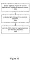
- FIG. 10 flowcharts one embodiment of a method for generating the program flatfile
- FIGS. 11A-11C illustrate the structure and deployment of the program flatfile, according to one embodiment.
- FIG. 12 flowcharts one embodiment of a method for deploying and executing a program on an embedded device.
- Each of the two submitted discs includes:
- FIGS. 1A and 1B illustrate embodiments of embedded system for executing programs.
- the system may include a computer system 102 coupled through a network 104 (or other transmission medium) to an embedded device 110 , also referred to as a target device 110 .
- the computer system 102 may be coupled to the target device 110 via an intermediate hub 108 , which may communicate with the computer system 102 over the network 102 , and which may communicate with the target device 110 via wireless means.
- the computer system 102 may be of any various types of computer systems.
- Computer system 102 may include a processor, a memory medium, as well as other components as may typically be found in a computer system.
- the memory medium of the computer system may store a program development environment for creating programs.
- the computer system 102 is described in more detail below with reference to FIG. 3 .
- the term program is intended to include text-based or graphical instructions which are executable, compliable, and/or interpretable by a processor or programmable hardware element (such as a Field Programmable Gate Array (FPGA)) to perform a specified function or functions.
- FPGA Field Programmable Gate Array
- the program development environment is a graphical program development environment for creating graphical programs.
- An exemplary graphical program development environment is LabVIEW development environment offered by National Instruments Corporation.
- a user may create a program on a computer system, and computer system 102 may provide the program to target embedded device 110 , optionally via hub device 108 .
- Target device 110 may include a processor and memory medium for executing programs, such as graphical programs.
- the target device 110 executes programs, e.g., graphical programs, received from the computer system over the network 104 .
- the computer system 102 sends the program to the hub device 108 over the network 104 , and the hub device 108 operates to deploy the programs to the target device 110 in a wireless fashion, and the program executes on target device 110 .
- the target device 110 may be implemented in different devices, such as, for example, a device with an ARM processor, as described below, a PXI chassis which includes an embedded device card, or any other processor based device suitable for embedded systems.
- One exemplary target device 110 is a smart sensor (e.g., a smart camera).
- the target device 110 may include a programmable hardware element, such as an FPGA.
- the target device 110 may be operable to receive a hardware configuration file, e.g., a netlist, which encodes a desired functionality, and to deploy the hardware configuration file to the FPGA, thereby configuring the FPGA to perform the desired functionality.
- a hardware configuration file e.g., a netlist
- Target device 110 may be connected to computer system 102 by a network 104 as shown.
- the network may be comprised of any of the various types of networks including local area networks (LAN), wide area networks (WAN), etc.
- LAN local area networks
- WAN wide area networks
- the Internet Target device 110 may also connect to computer system 102 through other communication mediums, such as a serial bus, e.g., USB or IEEE 1394, a parallel bus, or through wireless means.
- the wireless communication mechanism may comprise any of various types of wireless transmission, including Blue Tooth, IEEE 802.11 (wireless Ethernet), RF communication, and other types of wireless communications, such as, for example, communication via satellite, and cell towers, such as used for cellular telephone communication, among others.
- the target device 110 may include or may be coupled to one or more sensors or actuators.
- the target device may include a radio and may be coupled to a sensor via wireless means.
- one or more of the sensors coupled to the target device 110 may be smart sensors, i.e., may include a processor and memory (and/or a programmable hardware element, such as an FPGA), and therefore may be operable to execute program code and/or receive commands from the target device 110 as a result of execution of the program code.
- an embedded device 110 may be coupled to the host computer 102 .
- the term “embedded device” refers to a small platform which includes dedicated hardware, and which includes a processor and memory (or FPGA) on which may be installed dedicated programs or software.
- An embedded device is typically designed to perform a defined task very well.
- an embedded device is typically not a device with general capabilities, such as a PC or PXI controller, for example, loaded with one or several plug-in boards, running a Microsoft OS with generous amounts of memory, system files, utilities, etc, that can be used as a measurement system, or as an office computer, or as a Web browser, etc.
- An example of an embedded system is an Internet remote camera, with dedicated hardware and software that implements the following tasks:
- embedded devices include a measurement device with a specific type of measurement hardware and/or software for taking certain measurements, a control measurement device with a specific type of hardware and/or software for performing certain control operations, etc.
- an embedded device generally includes both hardware and software. Additionally, embedded devices are generally built around a specialized hardware component, which is the “reason to exist” for these devices (like the camera in the above example).
- Other typical components include: a processor, such as an ARM processor, RAM and ROM memory, a storage medium, a display, one or more communication devices, and power and over-voltage protection components.
- flash memory is used for data storage in addition to RAM.
- FIG. 2 Block Diagram of the Data Acquisition System
- FIG. 2 is a block diagram of the system of FIG. 1A , according to one embodiment.
- the computer system 102 includes a program development environment 201 , e.g., a graphical program development environment, which facilitates development of programs, e.g., graphical programs, for implementing desired functions or operations, as well as a program execution system 203 , also referred to as the execution system 203 .
- the execution system 203 may be operable to execute programs developed with the program development environment 201 (or other program development environments).
- execution system may include at least one software program that is designed to execute a certain class of programs.
- LabVIEW programs utilize an execution system (a LabVIEW graphical program execution engine) that executes in a system in order to execute LabVIEW graphical programs.
- the execution system 203 may include a componentized or modular architecture, e.g., a componentized callback system, stored on the computer system for partial transfer to an external device, e.g., the target device 110 .
- the functions of the execution system 203 may be organized into modular components which may be operable to be transferred entirely or in part to the target embedded device 110 to facilitate execution of programs on the target embedded device 110 .
- the systems and methods are described in terms of graphical programs, although it should be noted that the invention is broadly applicable to other types of programs as well, e.g., text-based programs, etc., and is not intended to be limited to graphical programs.
- the computer system 102 may also store one or more programs 202 (e.g., graphical programs) which are executable via the execution system 203 (or portions thereof) to perform specified functions or operations, as desired.
- the graphical program 202 may be stored for transferal to the target embedded device 110 for execution.
- various components of the execution system 203 may be combined with respective portions of the graphical program 201 for transferal to the target device 110 for execution.
- the computer system 102 may also include a network interface 204 for communicating over the network 104 with devices on the network 104 .
- the network interface 204 may be an Ethernet interface for communicating over the Internet 104 . Further details of the computer system 102 are provided below with reference to FIG. 3 .
- the graphical program 201 may be provided from a first computer, and components of the execution system 203 necessary for execution of this graphical program may be provided from a second different computer system.
- the target device 110 includes an operating system 210 , e.g., a real-time operating system (OS), for managing program execution, managing device resources, and communications in embedded devices, as is well known in the art.
- OS real-time operating system
- Examples of real-time operating systems 210 include, but are not limited to, Linux, NetBSD, vxWorks, eCos, and Windows CE. Due to size and performance issues, the eCos real-time operating system may be particularly suitable for use in the embedded target device 110 , although other real-time operating systems are also contemplated.
- the target device 110 may also include a target execution system (or “minimal execution system”) 205 , which preferably is a minimal embedded graphical program execution system 205 , and which may include a subset of the execution system 203 stored on the computer system 102 , mentioned above.
- the minimal execution system 205 may be optimized to minimize the memory footprint on the target device 110 , as described below with reference to FIG. 5 .
- the minimal execution system 205 may comprise an execution system virtual machine.
- the minimal execution system 205 may facilitate execution of graphical program(s) 202 by the target device 110 .
- the graphical program 202 stored on the computer system 102 may be combined with one or more components of the componentized callback system of execution system 203 to generate a flatfile 207 which may be transferred to the target embedded device 110 .
- the flatfile 207 may be directly executable by the target device 110 .
- the flatfile 207 may be used in constructing a combined program 202 A on the target device 110 , wherein the combined program 202 A may be executed on the target device 110 .
- the flatfile 207 and the combined program 202 A are described in detail below.
- the target embedded device 110 may also include software for performing various functions related to the present invention, such as a program linker/loader, which in various embodiments may be comprised in the real-time OS, the minimal execution system 205 , or may be stored and executed as a separate program.
- a program linker/loader which in various embodiments may be comprised in the real-time OS, the minimal execution system 205 , or may be stored and executed as a separate program.
- FIG. 3 Computer System Block Diagram
- FIG. 3 is a block diagram for a computer system 102 suitable for implementing various embodiments of the present invention. More specifically, the computer system 102 may be operable to store and download to the target device 110 a graphical program that is configured to perform a specified function. Embodiments of a method for transmitting and executing the graphical program are described below.
- the computer system 102 may be any type of computer system, including a personal computer system, mainframe computer system, workstation, network appliance, Internet appliance, personal digital assistant (PDA), television system or other device.
- PDA personal digital assistant
- the computer system can be broadly defined to encompass any device having at least one processor that executes instructions from a memory medium.
- the computer may include at least one central processing unit or CPU 160 which is coupled to a processor or host bus 162 .
- the CPU 160 may be any of various types, including an x86 processor, e.g., a Pentium class, a PowerPC processor, a CPU from the SPARC family of RISC processors, as well as
- the computer system 102 may include a memory medium(s) 166 on which one or more computer programs or software components according to one embodiment of the present invention may be stored.
- the memory medium may store a graphical program execution system, as well as one or more graphical programs, as described above.
- the memory medium may store a graphical programming development environment application used to create and/or execute such graphical programs.
- the memory medium may also store operating system software, as well as other software for operation of the computer system.
- memory medium is intended to include an installation medium, e.g., a CD-ROM, floppy disks 104 , or tape device; a computer system memory or random access memory such as DRAM, SRAM, EDO RAM, Rambus RAM, etc.; or a non-volatile memory such as a magnetic media, e.g., a hard drive, or optical storage.
- the memory medium may comprise other types of memory as well, or combinations thereof.
- the memory medium may be located in a first computer in which the programs are executed, or may be located in a second different computer which connects to the first computer over a network, such as the Internet. In the latter instance, the second computer may provide program instructions to the first computer for execution.
- Various embodiments further include receiving or storing instructions and/or data implemented in accordance with the foregoing description upon a carrier medium.
- Suitable carrier media include a memory medium as described above, as well as signals such as electrical, electromagnetic, or digital signals, conveyed via a communication medium such as networks and/or a wireless link.
- the memory medium 166 may be coupled to the host bus 162 by means of memory controller 164 .
- the host bus 162 may be coupled to an expansion or input/output bus 170 by means of a bus controller 168 or bus bridge logic.
- the expansion bus 170 may be the PCI (Peripheral Component Interconnect) expansion bus, although other bus types can be used.
- the expansion bus 170 includes slots for various devices, such as a network interface card 114 , a video display subsystem 180 , and hard drive 1102 coupled to the expansion bus 170 .
- graphical program or “block diagram” is intended to include a program comprising graphical code, e.g., two or more interconnected nodes or icons, wherein the interconnected nodes or icons may visually indicate the functionality of the program.
- the nodes may be connected in one or more of a data flow, control flow, and/or execution flow format.
- the nodes may also be connected in a “signal flow” format, which is a subset of data flow.
- the terms “graphical program” or “block diagram” are each intended to include a program comprising a plurality of interconnected nodes or icons which visually indicate the functionality of the program.
- a graphical program may also comprise a user interface or front panel.
- the user interface portion may be contained in the block diagram or may be contained in one or more separate panels or windows.
- the user interface of a graphical program may include various graphical user interface elements or front panel objects, such as user interface controls and/or indicators, that represent or display the respective input and/or output that will be used by the graphical program or VI, and may include other icons which represent devices being controlled.
- the user interface or front panel may be comprised in a single window of user interface elements, or may comprise a plurality of individual windows each having one or more user interface elements, wherein the individual windows may optionally be tiled together.
- the user interface or front panel may comprise user interface or front panel objects, e.g., the GUI, embedded in the block diagram.
- the user interface of a graphical program may display only output, only input, or both input and output. Further, in some embodiments the user interface operates as a front panel, wherein the user can interactively control or manipulate the input being provided to the graphical program during program execution and can view resulting output.
- Examples of graphical programming development environments that may be used to create graphical programs include LabVIEW, DasyLab, and DiaDem from National Instruments, VEE from Agilent, WiT from Coreco, Vision Program Manager from PPT Vision, SoftWIRE from Measurement Computing, Simulink from the MathWorks, Sanscript from Northwoods Software, Khoros from Khoral Research, SnapMaster from HEM Data, VisSim from Visual Solutions, ObjectBench by SES (Scientific and Engineering Software), and VisiDAQ from Advantech, among others.
- the system uses the LabVIEW graphical programming system available from National Instruments.
- FIG. 4 A Embedded Device Hardware Configuration
- FIG. 4A illustrates a hardware configuration of one embodiment of a target embedded device, as shown in FIGS. 1A , 1 B, and 2 . It should be noted that the embodiment shown is intended to be exemplary only, and is not meant to limit the target embedded device to any particular architecture, components, size, or form.
- the target embedded device 110 may include an I/O connector 402 coupled to a 4-channel multiplexer (MUX) 402 , connected to a 4-channel 16-bit ADC 408 , a temperature sensor 404 , a micro-controller with internal flash program memory and data SRAM 406 , and Ethernet port 414 .
- power is provided by a 5 volt DC power supply 412 .
- the processor 406 an ATMEL ARM Thumb AT91FR4081, has a high-performance 32-bit RISC architecture with high-density 16-bit instruction set and very low power consumption.
- the Atmel AT91FR4081 406 provides a powerful, flexible, and cost-effective solution to the minimal embedded control application. Significant board size reduction is also noted as a benefit.
- FIG. 4 B Embedded Device Hardware
- FIG. 4B illustrates the embedded hardware of FIG. 4A , according to one embodiment. As FIG. 4B shows, the hardware components included in the target embedded device 110 facilitate an extremely compact form factor.
- FIG. 4 C Another Example of Embedded Device Hardware
- FIG. 4C illustrates another embodiment of the embedded target device 110 , according to one embodiment.
- substantially all of the functionality included on the board is modular.
- different I/O boards 420 may be selected and plugged-in depending on the type of sensors required by the application.
- components which may be provided by additional modules (e.g., cards) have been remove, such as the temperature sensor 404 and the ADC 408 .
- a micro-controller with internal 1 MB of flash program memory and 128 kb of data SRAM is connected via SPI (serial peripheral interface) to an analog small form-factor DAQ slot, and is further connected via a digital bus to a digital small form-factor DAQ slot.
- SPI serial peripheral interface
- This embodiment may be particularly suited for smart sensing, computing, and control, due to the design emphasis on modularity.
- FIG. 5 Minimal Execution System
- FIG. 5 illustrates the determination of a reduced or minimal set of functionality needed to execute graphical programs.
- This minimal set is included in the minimal graphical program execution system 205 which is installed on the target embedded device 110 , and which operates to execute the (combined) graphical program (via the graphical program flatfile 207 ) on the target device 110 .
- FIG. 5 compares a minimal graphical program execution system 205 with an un-optimized (for small memory footprint) graphical program execution system 500 .
- the graphical program execution system 500 may include an execution engine 502 , a network manager 504 , a callback system 506 , and other components 508 .
- an execution engine 502 there may be as many as (or more than) 30 components, and so the execution system may be quite large.
- Such a system may operate under a real-time OS, such as Linux, which has a size of roughly 1.5 MB (mega-bytes).
- the amount of available memory may be quite large, and hence there is typically no need to reduce the size of the graphical program execution system.
- the target device may have a limited memory size, e.g., due to power and/or cost constraints.
- a real-time OS 210 for the embedded target device 110 such as eCos, may only be 50 KB in size, and so the execution engine is preferably scaled down accordingly to run on the embedded device 110 under the embedded real-time OS 210 . This may be accomplished by modifying or removing various sub-systems of the execution system 500 that are not required for basic execution.
- the minimal execution system may include only a portion of the execution engine 502 A, as shown, along with a substantially modified network manager 504 A. Other components may be omitted altogether.
- a minimal execution system 205 may be generated with greatly reduced size, and somewhat reduced functionality in order to fit on the embedded target device 110 .
- the minimal execution system 205 may be the absolute smallest executable execution system 205 , or simply a reduced version of the execution system 205 including a core set of functionality.
- the callback system 506 may be omitted from the minimal execution system 205 .
- the callback system 506 may be replaced with a componentized or modular callback system 206 which is stored on the host computer 102 , and which may be transferred in part to the target device 110 depending on the needs of the particular graphical program.
- the componentization of the callback system 506 is described below with reference to FIGS. 7 and 8 .
- FIG. 6 Method of Creating a Minimal Graphical Program Execution System
- FIG. 6 flowcharts one embodiment of a method for creating a minimal graphical program execution system, as described above with reference to FIG. 5 . It is noted that in various embodiments, one or more of the steps may be performed in a different order than shown, or may be omitted. Additional steps may also be performed as desired.
- this may include removing such subsystems as the web server, XML support, and the callback table.
- all the functions that are named in the callback table (which are candidates for modularization and aren't required for the simple VIs) may be removed.
- a code coverage test may be perform in order to find and remove the functions that were not called in executing the simple VI (or a set of simple VIs).
- the resulting code comprises an initial version of the minimal execution engine 205 .
- the resulting code may be profiled to determined how much code memory and RAM memory it occupies, and to decide which of the remaining subsystems are too large and should be redesigned. For example, for the system described above based on the ARM processor, a target memory footprint of 50K may require trimming those subsystems that are required and are too large in the original execution system. As an example, the network manager and type system may need to be redesigned if they were implemented with too large buffers in the original execution system.
- VI20BJ components for converting VIs to object files (VI20BJ) and for generating the modules for the flatfile (FLATFILE) may be created. Further information regarding the generation of object files for VIs is provided below in the section titled VI Object Files.
- a minimal execution engine 205 may be constructed by removing all but the minimum functionality required to execute a VI (graphical program), including most or all of the callback system 506 , leaving the portion of the execution engine 502 A and a modified network manager 504 A, as described above. Such a minimal execution system 205 may then be suitable for loading and executing on an embedded device 110 .
- the minimal execution system may comprise an execution system virtual machine.
- an operating system may be optimized, modularized, and/or modified to minimize the footprint on the target device 110 .
- the operating system may be analyzed to determine a minimal kernel or core functionality necessary for the OS to operate.
- the minimum functionality may include a simple Basic I/O Service (BIOS) and/or a minimum communication service, such as a TCP/IP service, as is well known in the art.
- the minimum functionality may include a simple downloading capability or functionality, e.g., a download protocol.
- the minimum functionality may include one or more of: a simple BIOS, a minimum network communications protocol (e.g., TCP/IP), and/or a minimum download capability.
- the minimum functionality may include a hardware and/or software checking capability.
- Other functions or services of the OS such as I/O, memory management (e.g., trash collection, etc.) etc., may be modularized or partitioned such that subsets of the functions or services needed for a particular application or device may be determined and transmitted as needed.
- a distributed, “on-demand” OS may be created which includes the kernel (or minimum functionality), and one or more transferable OS modules which provide additional OS functionality in a modular fashion.
- the minimum functionality may facilitate subsequent downloading of support libraries and executing kernel components, i.e., in one embodiment, the minimum functionality may be just enough to allow the device to download further basic OS capabilities, including portions of the kernel and/or the BIOS. In another embodiment, these further basic OS capabilities may be included with an application, as described in detail below.
- the OS kernel or core functionality may reside on the target device 110 , and may be executable to perform basic OS functionality on the device. Then, based on analysis of the application (e.g., a graphical program and/or the desired task, and/or the target device), one or more OS modules may be selected to provide particular needed services. These OS modules may then be transmitted to the target device 110 and installed (e.g., by the kernel or other loader program) to augment the basic OS functionality provided by the kernel, after which the OS (now extended) may be operable to provide the additional OS services or functionality.
- the application e.g., a graphical program and/or the desired task, and/or the target device
- these OS modules may then be transmitted to the target device 110 and installed (e.g., by the kernel or other loader program) to augment the basic OS functionality provided by the kernel, after which the OS (now extended) may be operable to provide the additional OS services or functionality.
- the one or more OS modules may be transmitted alone, or along with or as part of the target application.
- the one or more OS modules may be included in a flatfile 207 (or other structure or file) along with modules from the graphical program, and possibly also with modules (components) of the modular callback system 206 .
- FIG. 7 Componentization of the Graphical Program Callback System
- FIG. 7 illustrates the process of componentizing a monolithic graphical program callback system 506 to generate the modular graphical program callback system 206 , according to one embodiment. It should be noted that the callback system of FIG. 7 is a highly simplified model which is intended only to illustrate the process, and is not meant to represent an actual callback system.
- the monolithic graphical program callback system 506 includes a plurality of functions A-K ( 702 - 722 ) with varying dependencies.
- the functions are arbitrarily stored in many different files, which generally accumulate over time as the function library is developed.
- locating functions for linking and execution may be difficult and expensive, since functional dependencies may span numerous files in a substantially haphazard manner.
- many unnecessary functions may be included due to the fact that they happened to be located in the same files as need functions, thus, the resulting memory footprint of the executable may be unnecessarily large.
- function A 702 calls function B 704 and function C 706 .
- Function B 704 calls function D 708 , and function C 706 calls function E.
- function A 702 has a dependency on function B 704 , function C 706 , function D 708 , and function E 710 .
- a first module, module 1 762 may include function A 702 , function B 704 , and function D 708 , as indicated in the modular callback system 203 .
- Module 2 764 includes function C 706 and function D 708 , as shown.
- Module 3 766 includes function F 712 , function G 714 , function H 716 , function I 718 and function J 720 . Note that module 1 762 and module 3 766 both depend on module 2 764 (since both function A 702 and function F 712 call function C 706 ). This module dependency relationship may be maintained in a module dependency table 730 or its equivalent. As FIG. 7 also shows, function K is independent of any other functions, and so has its own module, module 4 768 .
- each module may be stored in a separate file, greatly easing the task of a dependency checker when selecting modules/files needed by the graphical program 202 , i.e., for inclusion in the flatfile 207 .
- a method for performing this componentization is described below with reference to FIG. 8 .
- FIG. 8 Method for Componentizing a Graphical Program Execution System
- FIG. 8 flowcharts one embodiment of a method for componentizing a graphical program execution system, such as, for example, LabVIEW RT. More specifically, as described above with reference to FIG. 7 , the method componentizes or modularizes a set of functions (e.g., the function library) of the execution system, also referred to as the callback system of the execution system, by grouping functions in files or modules based on dependencies.
- a set of functions e.g., the function library
- the original source code of the callback system includes a set of files that each contains functions that may call other functions, that may call other functions, etc., that belong to other files. If a function's dependencies extend into several files, it may be difficult or impossible for a dependency checker to identify and retrieve the function. To facilitate a dependency checker being able to select from the callback system source code only those functions that are needed by a particular application, an attempt may be made to place each function with it's dependencies into a single file. This “complete” function file (e.g., with *.cpp extension) may comprise a module.
- componentization of the graphical program execution engine may include the creation of modules, or *.cpp files, that completely (or almost completely) describe a function.
- each function may be analyzed with respect to its functional dependencies to determine whether to place the function in a separate module or in a module with another function. For example:
- a next function e.g., function A
- a next function such as from the callback system of the graphical program execution engine. Then, a determination may be made as to whether function A has dependencies, i.e., calls a function B, as indicated in 804 . If function A has no dependencies, i.e., does not call function B, then a module or file may be created for function A, as shown in 808 .
- function A does call function B
- a determination may be made as to whether function B is also called by another function, e.g., function C. In other words, the method may check to see if any other function has a dependency on function B. If no other function calls function B, then in 807 a module or file may be created containing both function A and function B.
- function B If in 806 it is determined that function B is called by function C, then separate modules or files may be created for function A and function B, respectively. Said another way, if function B may be legitimately included in multiple modules (or files), then function B may be given its own module or file. It should be noted that in various embodiments, dependencies between modules may be stored either in the modules themselves or in some type of module dependency table or its equivalent.
- function A calls function B, and function B is only called by function A
- a module or file containing function A's definition may also contain function B's definition.
- the dependency checker will know that function A and function B are interrelated and part of the same file. If function A calls function B, and function B is also called by function C, then function A's module or file will not contain function B in its definition file, and so function B's definition may be included in a separate file (or module).
- the functions of a callback system in a graphical program execution engine may be modularized to allow the dependency checker to find and retrieve only those modules or files that are needed by the application, where the modules or files are organized to minimize the number of unnecessary functions included in the graphical program flatfile.
- FIG. 9 Generication of the Graphical Program Flatfile
- FIG. 9 graphically illustrates the process of generating a graphical program flatfile 207 from graphical program 202 and the modular callback system 206 .
- a dependency checker program or process may analyze the graphical program 202 with respect to the modular callback system 206 to determine required modules 902 .
- function K 722 is executed, then function C 706 (which calls function E 710 implicitly) is executed.
- function E 710 is executed (explicitly).
- the graphical program not only indicates the functions called, but the sequence of execution, as well.
- the dependency checker may thus may determine that module 2 764 and module 4 768 are required by the graphical program. This information may then be used in conjunction with execution sequence information from the graphical program 202 to generate the flatfile, as indicated in FIG. 10 . Further details of the flat file are provided below with reference to FIGS. 10 and 11 A- 11 C.
- one or more object files may be produced, e.g., via a utility such as VI20BJ or its equivalent.
- a utility such as VI20BJ or its equivalent.
- the reasoning behind this approach is due to the storage limitations of many embedded devices. For example, loading an entire VI to the target device 110 may require more RAM than is available on the device, and execution of VIs directly from flash may not be possible because there is not enough RAM memory to copy these VIs into RAM and execute from there.
- the term “program” may refer to the original source code of a program (e.g., the graphical diagram and underlying code, or text source code, such as C code), to object code generated from the source code, or to executable machine code generated from the source or object code.
- VI20BJ linker/loader may be developed based on the idea that VIs can be saved, not in their native format, but as object files, such that an ordinary C linker may be used to process them—i.e. to transform them into shared objects that can be loaded at runtime into the target device 110 .
- This approach may make generation of executables from VIs easy and straightforward when space is limited.
- VI20BJ or its equivalent is a mechanism to transform a VI (ex: add_int.vi) into an object file (ex: add_int.o).
- linkinfo describes connections made from a VI to various entities, e.g., subVIs, external functions etc.
- an object file is substantially a file comprising of blocks of information (e.g., code, data, etc.), symbol information, and relocation information.
- the steps taken to create an object file from a VI may include:
- Performing the steps described above may generate an object file that contains all the information needed by a VI to run, and that also includes symbol and relocation information used to connect this VI with other VIs or modules.
- FIG. 10 Method for Generating the Graphical Program Flatfile
- FIG. 10 is a high-level flowchart of one embodiment of a method for generating the graphical program flatfile 207 , as illustrated in FIG. 9 .
- one or more of the steps may be performed in a different order than shown, or may be omitted. Additional steps may also be performed as desired.
- a graphical program 202 may be analyzed with respect to function dependencies to generate a list or collection of required modules.
- a dependency checker residing on the host computer system 102 may determine the functions used in the graphical program, then select modules from the modularized callback system 206 which contain those functions to generate required modules 902 .
- the graphical program 202 may be analyzed to determine an execution sequence or order of the functions called by the program (or by other functions in the program 202 ). In other words, the program flow for the graphical program 202 may be determined.
- the flatfile 207 may be generated based on the required modules 902 and the execution sequence for the program.
- the flatfile 207 may be generated by including the required modules 902 in the flatfile 207 along with sequencing information and/or module dependency information.
- An exemplary structure and format of the generated flatfile 207 is presented below with reference to FIGS. 11A-11C .
- the flatfile 207 may be generated from an object file and a symbol map of the target executable (the graphical program).
- the object file is named add int.o (for adding two integers) and the flatfile name, will be add_int.flat.
- a symbol map (named mb.sym) may be generated from the graphical program, e.g., by using a special tool, e.g., a symdump tool.
- the symbol map contains all the global symbols of the graphical program along with the sections where they belong, and their addresses relative to the beginning of the section.
- Section names of the graphical program may then be extracted (e.g., from mb.sym), and numbered, e.g., beginning with one.
- Section names of add_int.o may then be extracted and numbered, e.g., beginning with 100.
- symbol lookup may be done at the time of the flatfile creation.
- Relocation information in an object file may include the address where the relocation is needed and the symbol name for the relocation.
- the relocation information in a flatfile may comprise tuples (clusters, structures, etc.) of ⁇ [address where the relocation is needed (uInt32)], [the target section (uint16)], [the target address relative to the start of the start section] ⁇ . Further information regarding relocation is provided below.
- the symbol name may be searched for in mb.sym and add_int.o, and, if the symbol is not found, then an error message may be generated and the method terminated. If the symbol is found, the relocation may be written to the flatfile, i.e., to add_int.flat.
- each section's content may be written to the flatfile.
- writes to the flatfile 207 may be made in accordance with the formats for relocation, etc., for a flatfile, described below.
- flatfiles are “targeted”.
- flatfiles are generally built to be loaded by a specified program.
- a crash or error may occur if another program tries to load a flatfile that was not built for it.
- the version of the symbol map should match the version of the graphical program. This version compliance may be facilitated by using a “build timestamp” in the application and in the mb.sym, so verification of the “version match” is possible.
- Relocation refers to writing the code section of an application at a certain memory address and preparing the code for execution. Preparation includes modification of the code according to a relocation table such that at execution time the code is able to access the variables and functions that it needs for its task. Examples of relocation are presented below.
- a program, at compile time, is set to run at certain memory addresses, say Xtext for the code section and Xdata for the data section.
- Xtext for the code section
- Xdata for the data section.
- the code and data sections of the program may be placed in different memory locations on the target device, say Ytext and Ydata.
- variable i (Xdata+100) (an offset of 100, for example, with respect to Xdata)
- the relocation process uses the Relocation Table to determine the address in the code section for the instruction
- one or more of the following constraints may apply to the target device:
- target flash should be large enough to be able to store the flatfile code, constructor, destructor and read-only sections.
- target RAM should be large enough to store the flatfile data section and also the largest relocation table.
- i is an un-initialized variable, so it may be stored in the un-initialized data (.bss) section.
- j is a variable that will contain the address of variable i, so after being initialized it may be stored in the data section. Because j will eventually have to contain the address of i, a relocation may be necessary in the data section to the address of j.
- FIGS. 11 A- 11 C Structure and Deployment of the Graphical Program Flatfile
- FIGS. 11A-11C illustrate the structure and deployment of the graphical program flatfile 207 , according to one embodiment.
- FIG. 11A illustrates one embodiment of the contents of the modules used to build the flatfile 207 .
- FIG. 11B illustrates the structure of the flatfile 207 , according to one embodiment.
- FIG. 11C illustrates the deployment of the minimal graphical program execution system 205 and the constructed combined program 202 A.
- a module 1100 may include three components: a sections component 1102 , a symbols component 1104 , and a relocation table 1106 .
- the module is a piece of C or C++ code contained in one or more C or C++ files. Every module may be compiled into an object file which contains the executable code and the data generated by the compiler for a specific module, along with symbolic and relocation information for that module, and other information, such as debug info, comments, etc.
- the sections component 1102 may include six sections which represent various aspects of the module 1100 , as shown in FIG. 11A . More specifically, the sections may include a code section 1112 which is the program code for the module, a data section 1113 , a constructor 1114 for the module, a destructor 1115 for the module, a un-initialized data section 1116 , and a data read-only section 1117 (i.e., for constants). A section may comprise a range of addresses with no gaps; all data in those addresses may be treated the same for some particular purpose.
- the symbols component 1104 includes the variables and function names for the module. A symbol is a name associated with a given address in a given section. The symbolic and relocation information from the object file of the graphical program can be used to determine the dependency relation between modules.
- relocation is the process that makes an object file able to run at a given address.
- the information (table) that the relocation process uses is referred to as relocation information (or the relocation table) and is preferably included in the flatfile 207 .
- the relocation table 1106 also referred to as an address table, provides the relative addresses for the symbols (variables and functions) with respect to the program on the host computer 102 .
- This relocation information may be used by the target device to construct the combined program 202 A, adding an address offset to the addresses in the relocation table 1106 to generate correct locations for the symbols in the context of the target device 110 .
- the object file may contain sections such as:
- each module 1100 may be included in the flatfile 207 , as shown in FIG. 11B .
- the flatfile 207 may include an initial segment 1120 (reading left to right) which includes information regarding the module information in the flatfile 207 .
- this section may be about 100 bytes in size, and may include such information as the number of sections in the flatfile, the size of each section in bytes, and the type of each section, e.g., code 1112 , data 1113 , etc.
- each module segment may include the module information shown in FIG. 11A , i.e., each module segment may include relocation table 1106 and sections 1102 for a respective module 1100 .
- FIG. 11C illustrates the deployment of the minimal execution system 205 and the combined program 202 A on the target device 110 .
- the minimal execution system 205 may be divided between RAM 1130 and flash memory 1140 on the target embedded device 110 .
- the RAM 1130 is of size 128 k and stores data and un-initialized data for the minimal execution system 205 .
- 128 k of the flash memory 1142 is used to store the real-time OS (e.g., eCos) and the code and read-only data for the minimal execution system 205 .
- the remainder of the flash memory 1140 may be used to store the combined program 202 A which may be constructed based on the flatfile 207 .
- the RAM 1130 may also be used to store data during execution of the combined program 202 A.
- the flatfile 207 may include module information for functions of the graphical program 202 and for functions included from the modular callback system.
- the functions (with variables) for the graphical program 202 have been combined with the execution system functions required to execute those graphical program functions.
- This module information also includes relative address information for re-locating the functions in the memory space of the target device 110 .
- the flatfile 207 may be transmitted to the target device 110 where a flatfile loader may execute to receive the flatfile 207 and construct the combined program 202 A. Further details of the process of constructing the combined program 202 A from the flatfile are provided below with reference to FIG. 12 .
- sec_desc[sec_nr] An array of sec_nr section descriptors. See the format of sec_desc below;
- sec_content[sec_nr] An array of sec_nr with section contents. See the format of sec_content below;
- rel_desc Relocations for this section. See bellow for rel_desc structure
- section_data the raw data of the section
- rel_data[rel_nr] an array of rel_nr relocations data—See bellow for the rel_data structure
- target_addr (uInt32)—the address relative to target section address where the relocation should point;
- rel_type (uInt16)—the type of the relocation.
- FIG. 12 Method for Deploying and Executing a Graphical Program
- FIG. 12 flowcharts one embodiment of a method for creating, deploying, and executing a graphical program on an embedded device. More specifically, a method is described for creation and deployment of programs on the target device 110 . It is noted that in various embodiments, some of the steps may be performed in a different order than shown, or may be omitted. Additional steps may also be performed. As shown, this method may operate as follows.
- the user first may create a program that is operable to execute within the target embedded device, as indicated in 1202 .
- the user may be aware of the one or more sensor devices 120 which will be acquiring data in the system.
- the user may include code in the program which is operable to execute on the target device, and which operates to provide instructions to one or more of sensor devices 120 to direct sensor devices 120 to acquire data at certain times or based on certain detected events.
- the user may create a graphical program on computer system 102 .
- a graphical program may comprise graphical code, i.e., two or more interconnected nodes or icons which visually represent operation of the program.
- the user may place icons within the graphical program representing each of the respective sensor devices 120 that are being used.
- the user may also include graphical code in the program which operates to provide instructions to the respective sensor device icons, i.e., by connecting other graphical nodes to the sensor device icons in the graphical program.
- the graphical program may be created or assembled by the user arranging on a display a plurality of nodes or icons and then interconnecting the nodes to create the graphical program.
- data structures may be created and stored which represent the graphical program.
- the nodes may be interconnected in one or more of a data flow, control flow, or execution flow format.
- the graphical program may thus comprise a plurality of interconnected nodes or icons which visually indicates the functionality of the program.
- the graphical program may comprise a block diagram and may also optionally include a user interface portion or front panel portion.
- the user may assemble the user interface on the display.
- the user may use the LabVIEW graphical programming development environment to create the graphical program.
- the block diagram may be intended to execute on the target device 110 .
- the user interface code may remain on the host computer 102 and may execute on the host computer 102 to present the user interface on the host computer 102 during execution of the block diagram on the target device 110 .
- the user may interact with the user interface presented on the host computer 102 to provide input to and/or view output from the block diagram executing on the target device 110 .
- the graphical program may be created in step 1202 by the user creating or specifying a prototype, followed by automatic or programmatic creation of the graphical program from the prototype.
- This functionality is described in U.S. patent application Ser. No. 09/587,6102 titled “System and Method for Automatically Generating a Graphical Program to Perform an Image Processing Algorithm”, which is hereby incorporated by reference in its entirety as though fully and completely set forth herein.
- the graphical program may be created in other manners, either by the user or programmatically, as desired.
- the graphical program may implement a measurement function that is desired to be performed by the instrument.
- the instrument is an image acquisition device (e.g., a smart camera)
- the graphical program may implement an image processing function.
- the graphical program flatfile may be generated, as described above with reference to FIG. 10 .
- the graphical program includes a block diagram and a user interface
- only the block diagram portion may be used in generating the flatfile.
- the user interface may remain as code that executes on the host computer 102 .
- the flatfile may be transmitted to the target device 110 , e.g., over a network (or other transmission means).
- the user may cause the computer system to send the flatfile 207 over the network 104 (or other communication medium) to the target device 110 .
- the target device 110 may thus receive the flatfile 207 , and a loader/linker program on the target device 110 may construct the combined program 202 A based on the received flatfile 207 , as indicated in 1208 . Further details of one embodiment of this process are provided below in the Dynamic Linking section and the Example Process section.
- the target device 110 may execute the combined program 202 A.
- the target device 110 may send output data (e.g., acquired data or execution results) to the host computer 102 .
- the data may be transmitted to the computer 102 over the network 104 , e.g., through wired or wireless means.
- the target device 110 may send the output data through one or more intermediate devices, such as a hub device 108 .
- the host computer system 102 may display the received data in a GUI, and/or may otherwise process the received data to generate a certain result.
- the user constructs a GUI or front panel as part of the process of creating the graphical program, and this GUI code is executed on the computer system 102 to present the GUI on the display of the computer system 102 .
- the target device 110 in executing the program received from the computer system, may be directed by the program to provide certain commands to respective ones of sensor devices 120 to cause the sensor devices to acquire data and provide this acquired data to the target device.
- Examples of the types of commands that may be implemented by sensor devices 120 include, but are not limited to, single/multiple point read, writes (e.g., for configuration) start, and stop, among others.
- the minimal execution system 205 prior to sending the program to the target device 110 , the minimal execution system 205 may be deployed to the target device 110 . In another embodiment, the target device 110 may already have the execution system 205 installed.
- the target device 110 executes the program received from the computer system 102 , e.g., via the execution system 205 .
- the target device 110 may execute the program upon reception of the program from the host computer 102 .
- the user may send a command to the target device 110 over the network 104 invoking execution of the program by the target device 110 .
- the execution of the program results in some data being acquired or generated. These data may then be sent (e.g., over the network 104 or other communication medium) to the host computer system 102 , e.g., for display and/or analysis. In other embodiments, the acquired data may be sent to other systems.
- the target device 110 may use web server program 604 to publish the acquired data to a website, where a system with a web browser may then access the data.
- the target device may send the data to one or more other systems coupled to the network 104 (e.g., the Internet).
- the target device may send the acquired data to any networked devices, as desired.
- the flatfile 207 may comprise a sequence of sections and relocation tables.
- the sections can be code, data, constructors, etc.
- the code in its sections is relative, meaning that the instructions described in this code do not have real target addresses for the variables but rather some generic addresses, e.g., with respect to the beginning of the program.
- the program may include an instruction:
- the flatfile may be transmitted to the target device, say, for example, in chunks of 4 kbytes.
- the very first transfer contains the initial 100 bytes 1120 that give information regarding the total number of sections, their type, and size, and the relocation tables that come with them, as described above with reference to FIG. 11B . Based on this information memory on the target device 110 may be reserved to accommodate these sections.
- the constructed combined program may be executed. In another embodiment, the execution of the constructed combined program may occur as the flatfile is streamed to the target device 110 , as described below.
- the user creates a VI on the host computer 102 , named Delay.vi, and wishes to run this VI on the target device 110 .
- the VI is transformed into an object file named Delay.o.
- the modules required for running the VI are determined by a dependency checker executing on the host computer 102 , producing the following list (for example):
- the application VIs are converted into object files, and the required modules (that are also compiled into object files at this point) from the modular callback system 206 are determined. Then, all the object files pertaining to the application (using an ordinary C linker) are lined into a single object file which becomes the “application object file”. In other words, the following object files may be merged together:
- All code sections (of type text) with related relocation, symbol and debug information from Delay.o, memmove.o, mbCookie.o, mbOccur.o, and memcpy.o are assembled into one big code section (of type text) with related relocation, symbol and debug information in the resulting exampleVI.o.
- All data sections (of type data) with related relocation, symbol and debug information from Delay.o, memmove.o, mbCookie.o, mbOccur.o, and memcpy.o are assembled together into one big data section (of type data) with related relocation, symbol and debug information in the resulting exampleVI.o
- All constructor sections (of type .ctors) with related relocation, symbol and debug information from Delay.o, memmove.o, mbCookie.o, mbOccur.o, and memcpy.o are assembled together into one big constructor section (of type ctors) with related relocation, symbol and debug information in the resulting exampleVI.o.
- All code destructor (of type .dtors) with related relocation, symbol and debug information from Delay.o, memmove.o, mbCookie.o, mbOccur.o, and memcpy.o are assembled together into one big destructor section (of type dtors) with related relocation, symbol and debug information in the resulting exampleVI.o.
- All read_only sections (of type rodata) with related relocation, symbol and debug information from Delay.o, memmove.o, mbCookie.o, mbOccur.o, and memcpy.o are assembled together into one big read_only section (of type rodata) with related relocation, symbol and debug information in the resulting exampleVI.o.
- All un_initialized data sections (of type .bss) with related relocation, symbol and debug information from Delay.o, memmove.o, mbCookie.o, mbOccur.o, and memcpy.o are assembled together into one big un initialized data section (of type .bss) with related relocation, symbol and debug information in the resulting exampleVI.o.
- exampleVI.o contains:
- a typical object file has a very complicated internal structure and thus may not be suitable for sequential processing (on the target device 110 ). Therefore, in order to be able to load, dynamically link, and sequentially process an object file on the target device 110 , the object file may be processed into a different format called the flatfile, described above in detail.
- the flatfile is an object file that has a much simpler structure than a regular object file, and therefore it may be processed “on the fly” or sequentially on the target device 110 .
- a utility referred to as obj2flat, that transforms an object file into a flatfile, may be developed and used. Therefore, by running the obj2flat utility on exampleVI.o a single flatfile file named exampleVI.flat may be generated.
- the exampleVI.flat file may include:
- debug information may be omitted, while the symbol information may be used to create the relocation tables.
- the section table gives information for every section regarding the number of sections, the size of each section in bytes, and the type of each section, as described above.
- the section table may be required to pre-allocate the memory for the sections. The idea is that in the relocation process, all section addresses must be known, and so allocation of memory for sections is preferably the first step performed on the target device 110 .
- exampleVI.flat may be transferred to the target device.
- the target device has a network buffer in RAM that is 4K wide (although in other embodiment, the network buffer may be set to any size desired). Based on the size of this buffer, transfers of information from exampleVI.flat to target device RAM may be made in chunks of 4K.
- the very first 4K piece of exampleVI.flat arrives via the network into RAM on the target device 110 .
- This 4K of data contains the Section Table, Relocation Table for the Code Section, and some Code Section.
- the dynamic linker (or loader) that resides in Flash memory of the target device 110 may be a state machine with two run modes: read information, and process information.
- the dynamic linker enters read mode and starts reading the Section Table.
- the dynamic linker enters processing mode and stores the Section Table in another location in target RAM, then executes the Flash memory allocations for the sections described in the Section Table.
- the dynamic linker enters read mode, and reads the Relocation Table for Code Section.
- the dynamic linker enters processing mode and stores the Relocation Table for Code Section into target RAM at a different location than the 4K network buffer and the Section Table locations. Then it uses the information from the Relocation Table for Code Section to process the content of the Code Section that is already in the target RAM.
- the Relocation Table for Data Section is read into the 4K network buffer.
- the dynamic linker enters processing mode and stores the Relocation Table for Data Section into target RAM, overwriting the Relocation Table for Code Section.
- the dynamic linker uses the information from the Relocation Table for Data Section to process the content of the Data Section that is already in target RAM.
- a new 4K transfer from exampleVI.flat into the network buffer takes place, thereby overwriting the previous 4K information. Note that at this time, the Relocation Table for Data Section has been saved into target RAM, so the dynamic linker can proceed with processing of the Data Section by using information from the Relocation Table for Data Section.
- the program that is created on the computer system 102 may require use of program execution system 205 to execute the program.
- the program is a graphical program and requires graphical program execution system 205 to execute the program.
- the program execution system is configured in such a way so as to only transmit the minimum amount of a program execution system (i.e., a portion of the modular callback system 206 ) actually required by the program that is being executed.
- the program execution system is partitioned into a (minimal) base execution system, and a plurality of components for presenting different functionality that can be performed by a program.
- the base portion of the program execution system is only capable of executing the very simplest commands. This minimal engine may comprise the smallest set of commands which allows the other components to be executed.
- a software program executing on the computer may operate to analyze the program to determine the functionality contained in the program. Once the functionality of the program has been identified, the program uses the functionality to determine which of the respective components of the program execution system are actually required by the program. In one embodiment, the method determines the functionality of the program, and uses the functionality to index into a data structure or look-up table to determine which program execution system components will be required to execute this program.
- the computer system may operate to only provide the program execution system base portion and the respective components that are actually required to execute the program. Thus, the smaller amount of execution system code may be transmitted to the target device. This allows a smaller footprint for one or more of the target devices and/or the sensor devices.
- target device 110 may include a smaller processor and/or a smaller memory medium since a full program execution system is not required to be transmitted.
- an execution system analysis program may determine which execution system components are required for execution of the program.
- a deployment program may then assemble the required components of the execution system and the program, for example, by interspersing the required execution system components and the program together according to the order of execution of the program.
- These interspersed program execution system components and program may then be assembled into a file (i.e., the flatfile 207 ), and respective portions of the file transmitted to the target device 110 for execution.
- the flatfile 207 may be received by the target device 110 and used to construct a combined program 202 A including executable code from the program and executable code from the required execution system.
- This combined program 202 A may then be executed by the embedded device 110 .
- the combined program may also be stored in non-volatile memory of the embedded device for subsequent execution.
- successive portions of the file may be streamed to the target device 110 and/or sensor device 120 for dynamic execution.
- the target device may execute the program as it is streamed to the device.
- the sensor device 120 may receive a first portion of the file comprising a first portion of a program to be executed at a first portion of the execution system components that are used for executing this first portion of the program. After this first portion of the program has been executed along with the first portion of the execution system components, the first portion of the program may be flushed or removed from the memory of the sensor device. In a similar manner, the execution system components that are no longer required may be also removed from the memory.
- execution system components that may be required by other portions of the program to be executed may be retained in the memory for execution.
- the deployment program determines which execution system components may be required for a plurality of different portions of the program, and includes a variable or data structure or other indication with the execution system component to indicate that this component should not be flushed immediately after it has been executed, or others should be retained by target device 110 for execution with another part of the program.
- computer system 102 and/or target device 110 may then provide a second portion of the program interspersed with the second portion of the execution system components.
- the second portion of the file may be provided by the computer system to target device 110 .
- Operation then proceeds as above.
- computer system 102 may operate to provide respective portions of the deployment file to target device 110 for execution on an as needed basis, based on the memory availability or memory capacity of target device 110 .
- Target device 110 may receive the program that it is supposed to execute along with the execution system components used by that portion of the program, execute the program under direction of the execution system components, and then receive further portions of the deployment file, and so forth.
- computer system 102 may essentially provide a stream of the program and its corresponding execution system components to the target device according to the order of execution of the program.
- the computer system 102 , the target device 110 , and/or the hub device 108 may operate to execute a radio server program which is operable to discover remote or wireless data acquisition devices that enter into and exit from the wireless communication space that is within the range of the target device.
- the radio server executing on the target device may send out a wireless communication signal to query the presence of respective data acquisition devices 120 that are within the wireless communication range of the computer system 102 , target device 110 , or hub 108 .
- Any present data acquisition devices may respond to the queries to indicate its respective presence.
- the queries may be performed periodically, e.g., once permitted, once per hour, once per day, or at greater or lesser time frame granularities.
- the target device 110 may include a programmable hardware element, such as an FPGA, in addition to, or instead of, a processor.
- a programmable hardware element such as an FPGA
- the graphical program may be compiled to a hardware configuration file on the host computer system 102 , where the hardware configuration file is targeted at the FPGA on the target device 110 .
- the host computer may transmit the hardware configuration file to the target device 110 , where it may be stored, e.g., in a memory medium of the target device.
- the processor on the target device may then deploy the hardware configuration file onto the FPGA, after which the configured FPGA may execute to perform the desired function or operation.
- the target device may include two (or more) FPGAs.
- the host may stream the compiled hardware configuration file to the target device in portions which are each suitable for deployment and execution by respective ones of the FPGAs. Execution of the program may proceed in “ping-pong” fashion among the two or more FPGAs. For example, once a first portion of the hardware configuration file is received and deployed on a first FPGA, the configured first FPGA may execute, thereby performing a function encoded in the first portion of the hardware configuration file. While the first FPGA is executing the first portion of the hardware configuration file, a second portion of the hardware configuration file may be received and stored in the memory medium of the target device. The processor may then deploy this second portion of the hardware configuration program to a second FPGA on the target device 110 .
- the second FPGA may begin execution.
- execution of the first FPGA may be halted, and a third portion of the hardware configuration program may be received, stored in memory, and deployed onto the first FPGA (now inactive).
- the FPGAs may be dynamically configured in an alternating manner.
- this approach may be extended to more than two FPGAs, where more sophisticated techniques may be applied to determine which FPGA to configure with each successive portion of the hardware configuration program, e.g., round robin, longest inactive, size-based, etc.
Abstract
Description
| Name | Size | Modified |
| Build HUB list_(01).bmp | 6,090 KB | 9/5/02 |
| Build HUB list_(02).bmp | 6,079 KB | 9/5/02 |
| Build_crc.32.bmp | 6,113 KB | 9/5/02 |
| Change Name UI_(01).bmp | 6,092 KB | 9/5/02 |
| Change Name UI_(02).bmp | 6,087 KB | 9/5/02 |
| Change Name UI_(03).bmp | 6,077 KB | 9/5/02 |
| Change Name UI_(04).bmp | 6,097 KB | 9/5/02 |
| Change Name UI_(05).bmp | 6,087 KB | 9/5/02 |
| change_Name.bmp | 6,124 KB | 9/5/02 |
| change_net_config_UI_(01).bmp | 6,068 KB | 9/5/02 |
| change_net_config_UI_(02).bmp | 6,057 KB | 9/5/02 |
| cluster to net.bmp | 6,057 KB | 9/5/02 |
| crc32.bmp | 6,101 KB | 9/5/02 |
| daq_info.bmp | 6,090 KB | 9/5/02 |
| daq_list.bmp | 6,079 KB | 9/5/02 |
| Decode DISCOVERY_REPLY_(01).bmp | 6,079 KB | 9/5/02 |
| Decode DISCOVERY_REPLY_(02).bmp | 6,124 KB | 9/5/02 |
| Detect.bmp | 6,101 KB | 9/5/02 |
| discovery_reply_check.bmp | 6,113 KB | 9/5/02 |
| fix_name.bmp | 6,101 KB | 9/5/02 |
| Global var.bmp | 6,101 KB | 9/5/02 |
| Main Config 4_(01).bmp | 6,107 KB | 9/5/02 |
| Main Config 4_(02).bmp | 6,112 KB | 9/5/02 |
| Main Config 4_(03).bmp | 6,092 KB | 9/5/02 |
| Main Config 4_(04).bmp | 6,067 KB | 9/5/02 |
| Main Config 4_(05).bmp | 6,097 KB | 9/5/02 |
| Main Config 4_(06).bmp | 6,087 KB | 9/5/02 |
| net to cluster.bmp | 6,090 KB | 9/5/02 |
| net_conf_(01).bmp | 6,068 KB | 9/5/02 |
| net_conf_(02).bmp | 6,068 KB | 9/5/02 |
| net_info.bmp | 6,124 KB | 9/5/02 |
| New Name Dialog.bmp | 6,101 KB | 9/5/02 |
| store_net_info_(01).bmp | 6,101 KB | 9/5/02 |
| store_net_info_(02).bmp | 6,113 KB | 9/5/02 |
| Configurator.11b | 666 KB | 7/17/02 |
| demo-new.arm.11b | 619 KB | 7/17/02 |
FIGS. 1A and 1B—Embedded Systems
-
- it acquires images from the optical device,
- it compresses these images as GIF or JPEG files, or perhaps as MPEG streams, and
- it sends the images to a host computer upon request, using TCP/IP, HTTP, or multimedia streams.
- 1. Compiled code—executable binary code of a VI;
- 2. Data space—stores all the data that is required by the VI to run;
- 3. Data space type map—describes the data stored in the data space;
- 4. Connector panel—describes the inputs & outputs of a VI;
- 5. Front panel heap—hosts the controls, indicator & cosmetics etc.; and
- 6. Block diagram heap—hosts the nodes & wires that make up the block diagram.
- 1. The generated object file may be processed by an ordinary C linker (the VI may be linked to other support modules and eventually used to generate the flatfile).
- 2. It may be desirable to use the original execution mechanism of VIs on the
target device 110. - 3. The overhead induced by the new loading mechanism should be minimized.
- 4. Additional processing required after the VI is loaded by
target device 110, up to the point where it is ready to run, should be minimized. - 5. The object file size should be minimized.
- 1. placing the compiled code resulting from the VI into the section code of the object file, extracting the symbol information attached to the VI code, and adding relocation information for local and external function calls.
- 2. creating a data section for the object file containing initialized data, e.g., data space type map block of the VI, default data space, connector panel and VI Instrhandle structure (enabling some of the initialization for a VI on the host side), etc. Additionally, symbol information may be added to facilitate retrieval and use of information stored in this section.
- 3. creating a .bss section for un-initialized data and storing related symbol information there.
- 4. extracting patch information from the linkinfo block and storing this info in a data section (e.g., named linkdata). This information may include a set of symbol and relocations entries. The data section may be used to store links from the VI to other subVIs or external modules.
- 5. finally, calls may be generated for InitVI and UnInitVI functions (and stored in two special sections: .ctors and .dtors, of the object file). These functions may be responsible for VI initialization and disposal on the target device side.
-
- mov [Xdata+100], 0
meaning “move the value 0 at address Xdata+100”.
- mov [Xdata+100], 0
-
- Debug information for SectionA
SectionB
- Debug information for SectionA
-
- Move to variable I at address 510, the value 0 (I=0) has been corrected. In other words, the offset (500) has been added to the address. In one embodiment, the call may not be executed immediately, but rather may be stored or written in a code section of the
flash location 1140.
- Move to variable I at address 510, the value 0 (I=0) has been corrected. In other words, the offset (500) has been added to the address. In one embodiment, the call may not be executed immediately, but rather may be stored or written in a code section of the
Claims (42)
Priority Applications (8)
| Application Number | Priority Date | Filing Date | Title |
|---|---|---|---|
| US10/283,548 US8074201B2 (en) | 2002-07-10 | 2002-10-30 | Deployment and execution of a program on an embedded device |
| EP03763354A EP1530756B1 (en) | 2002-07-03 | 2003-07-03 | Wireless deployment / distributed execution of graphical programs to smart sensors |
| AT03763354T ATE480820T1 (en) | 2002-07-03 | 2003-07-03 | WIRELESS DISTRIBUTION / DISTRIBUTED EXECUTION OF GRAPHIC PROGRAMS TO INTELLIGENT SENSORS |
| EP08008168.0A EP2003549B1 (en) | 2002-07-03 | 2003-07-03 | Wireless deployment/distributed execution of graphical programs to smart sensors |
| DE60334107T DE60334107D1 (en) | 2002-07-03 | 2003-07-03 | WIRELESS DISTRIBUTION / DISTRIBUTED VERSION OF GRAPHIC PROGRAMS TO INTELLIGENT SENSORS |
| PCT/US2003/021352 WO2004006205A2 (en) | 2002-07-03 | 2003-07-03 | Wireless deployment / distributed execution of graphical programs to smart sensors |
| AU2003247935A AU2003247935A1 (en) | 2002-07-03 | 2003-07-03 | Wireless deployment / distributed execution of graphical programs to smart sensors |
| US12/286,137 US8239848B2 (en) | 2002-07-10 | 2008-09-29 | Incremental deployment and execution of a program on an embedded device |
Applications Claiming Priority (2)
| Application Number | Priority Date | Filing Date | Title |
|---|---|---|---|
| US39489502P | 2002-07-10 | 2002-07-10 | |
| US10/283,548 US8074201B2 (en) | 2002-07-10 | 2002-10-30 | Deployment and execution of a program on an embedded device |
Related Child Applications (1)
| Application Number | Title | Priority Date | Filing Date |
|---|---|---|---|
| US12/286,137 Division US8239848B2 (en) | 2002-07-10 | 2008-09-29 | Incremental deployment and execution of a program on an embedded device |
Publications (2)
| Publication Number | Publication Date |
|---|---|
| US20040010734A1 US20040010734A1 (en) | 2004-01-15 |
| US8074201B2 true US8074201B2 (en) | 2011-12-06 |
Family
ID=30117958
Family Applications (2)
| Application Number | Title | Priority Date | Filing Date |
|---|---|---|---|
| US10/283,548 Active 2028-08-20 US8074201B2 (en) | 2002-07-03 | 2002-10-30 | Deployment and execution of a program on an embedded device |
| US12/286,137 Expired - Lifetime US8239848B2 (en) | 2002-07-10 | 2008-09-29 | Incremental deployment and execution of a program on an embedded device |
Family Applications After (1)
| Application Number | Title | Priority Date | Filing Date |
|---|---|---|---|
| US12/286,137 Expired - Lifetime US8239848B2 (en) | 2002-07-10 | 2008-09-29 | Incremental deployment and execution of a program on an embedded device |
Country Status (1)
| Country | Link |
|---|---|
| US (2) | US8074201B2 (en) |
Cited By (38)
| Publication number | Priority date | Publication date | Assignee | Title |
|---|---|---|---|---|
| US20050220146A1 (en) * | 2004-03-31 | 2005-10-06 | Jung Edward K Y | Transmission of aggregated mote-associated index data |
| US20050254520A1 (en) * | 2004-05-12 | 2005-11-17 | Searete Llc, A Limited Liability Corporation Of The State Of Delaware | Transmission of aggregated mote-associated log data |
| US20050265388A1 (en) * | 2004-05-12 | 2005-12-01 | Searete Llc, A Limited Liability Corporation Of The State Of Delaware | Aggregating mote-associated log data |
| US20050267960A1 (en) * | 2004-05-12 | 2005-12-01 | Searete Llc, A Limited Liability Corporation Of The State Of Delaware | Mote-associated log creation |
| US20060004888A1 (en) * | 2004-05-21 | 2006-01-05 | Searete Llc, A Limited Liability Corporation Of The State Delaware | Using mote-associated logs |
| US20060046711A1 (en) * | 2004-07-30 | 2006-03-02 | Jung Edward K | Discovery of occurrence-data |
| US20060062252A1 (en) * | 2004-06-30 | 2006-03-23 | Jung Edward K | Mote appropriate network power reduction techniques |
| US20060079285A1 (en) * | 2004-03-31 | 2006-04-13 | Jung Edward K Y | Transmission of mote-associated index data |
| US20090300584A1 (en) * | 2008-05-30 | 2009-12-03 | Faus Norman L | Methods and systems for providing a demo appliance and migrating the demo appliance to a production appliance |
| US20120036505A1 (en) * | 2010-08-05 | 2012-02-09 | Kyocera Mita Corporation | Information Processing Apparatus that Automatically and Sequentially Displays Graphical User Interface Images and Recording Medium Storing Program |
| US20120096433A1 (en) * | 2010-10-18 | 2012-04-19 | Oracle International Corporation | Dependency resolution in polyphasic modules |
| US20120254836A1 (en) * | 2011-03-30 | 2012-10-04 | Timothy Aaron Storer | Apparatus, System, and Method for Managing Industrial Software Configurations |
| US8352420B2 (en) | 2004-06-25 | 2013-01-08 | The Invention Science Fund I, Llc | Using federated mote-associated logs |
| US9062992B2 (en) | 2004-07-27 | 2015-06-23 | TriPlay Inc. | Using mote-associated indexes |
| US9092243B2 (en) | 2008-05-28 | 2015-07-28 | Red Hat, Inc. | Managing a software appliance |
| US9235395B2 (en) | 2013-05-30 | 2016-01-12 | National Instruments Corporation | Graphical development and deployment of parallel floating-point math functionality on a system with heterogeneous hardware components |
| US9398082B2 (en) | 2008-05-29 | 2016-07-19 | Red Hat, Inc. | Software appliance management using broadcast technique |
| US9477570B2 (en) | 2008-08-26 | 2016-10-25 | Red Hat, Inc. | Monitoring software provisioning |
| US9652213B2 (en) | 2014-10-23 | 2017-05-16 | National Instruments Corporation | Global optimization and verification of cyber-physical systems using floating point math functionality on a system with heterogeneous hardware components |
| US10031490B2 (en) | 2013-03-15 | 2018-07-24 | Fisher-Rosemount Systems, Inc. | Mobile analysis of physical phenomena in a process plant |
| US10037303B2 (en) | 2013-03-14 | 2018-07-31 | Fisher-Rosemount Systems, Inc. | Collecting and delivering data to a big data machine in a process control system |
| US10168691B2 (en) | 2014-10-06 | 2019-01-01 | Fisher-Rosemount Systems, Inc. | Data pipeline for process control system analytics |
| US10282676B2 (en) | 2014-10-06 | 2019-05-07 | Fisher-Rosemount Systems, Inc. | Automatic signal processing-based learning in a process plant |
| US10296668B2 (en) | 2013-03-15 | 2019-05-21 | Fisher-Rosemount Systems, Inc. | Data modeling studio |
| US10318904B2 (en) | 2016-05-06 | 2019-06-11 | General Electric Company | Computing system to control the use of physical state attainment of assets to meet temporal performance criteria |
| US20190250912A1 (en) * | 2018-02-15 | 2019-08-15 | Wipro Limited | Method and system for migrating monolithic enterprise applications to microservice architecture |
| US10386827B2 (en) | 2013-03-04 | 2019-08-20 | Fisher-Rosemount Systems, Inc. | Distributed industrial performance monitoring and analytics platform |
| US10503483B2 (en) | 2016-02-12 | 2019-12-10 | Fisher-Rosemount Systems, Inc. | Rule builder in a process control network |
| US10649449B2 (en) | 2013-03-04 | 2020-05-12 | Fisher-Rosemount Systems, Inc. | Distributed industrial performance monitoring and analytics |
| US10649424B2 (en) | 2013-03-04 | 2020-05-12 | Fisher-Rosemount Systems, Inc. | Distributed industrial performance monitoring and analytics |
| US10657466B2 (en) | 2008-05-29 | 2020-05-19 | Red Hat, Inc. | Building custom appliances in a cloud-based network |
| US10656627B2 (en) | 2014-01-31 | 2020-05-19 | Fisher-Rosemount Systems, Inc. | Managing big data in process control systems |
| US10678225B2 (en) | 2013-03-04 | 2020-06-09 | Fisher-Rosemount Systems, Inc. | Data analytic services for distributed industrial performance monitoring |
| US10866952B2 (en) | 2013-03-04 | 2020-12-15 | Fisher-Rosemount Systems, Inc. | Source-independent queries in distributed industrial system |
| US10909137B2 (en) | 2014-10-06 | 2021-02-02 | Fisher-Rosemount Systems, Inc. | Streaming data for analytics in process control systems |
| US20210389943A1 (en) * | 2009-02-02 | 2021-12-16 | Enterpriseweb Llc | Resource processing using an intermediary for context-based customization of interaction deliverables |
| US11385608B2 (en) | 2013-03-04 | 2022-07-12 | Fisher-Rosemount Systems, Inc. | Big data in process control systems |
| US11472293B2 (en) | 2015-03-02 | 2022-10-18 | Ford Global Technologies, Llc | In-vehicle component user interface |
Families Citing this family (45)
| Publication number | Priority date | Publication date | Assignee | Title |
|---|---|---|---|---|
| US6876368B2 (en) * | 2001-08-14 | 2005-04-05 | National Instruments Corporation | System and method for deploying a graphical program to a PDA device |
| US7647562B2 (en) * | 2003-04-03 | 2010-01-12 | National Instruments Corporation | Deployment and execution of a graphical program on an embedded device from a PDA |
| EP1734432B1 (en) * | 2004-03-22 | 2011-09-21 | Digital Electronics Corporation | Display apparatus, program for causing a computer to function as the display apparatus and storage medium including the program |
| JP4604543B2 (en) * | 2004-04-30 | 2011-01-05 | 日本電気株式会社 | Computer, computer startup method, management server device, and program |
| US7503040B2 (en) * | 2004-09-30 | 2009-03-10 | International Business Machines Corporation | Configuring a shared library to accommodate relocatable data in a pervasive device |
| US7975233B2 (en) * | 2006-07-24 | 2011-07-05 | National Instruments Corporation | Automatic conversion of a textual language into a graphical program representation |
| US7954059B2 (en) * | 2006-07-24 | 2011-05-31 | National Instruments Corporation | Automatic conversion of text-based code having function overloading and dynamic types into a graphical program for compiled execution |
| US7877727B2 (en) * | 2006-08-18 | 2011-01-25 | Bitrouter | Hierarchical state programming with a markup language |
| US8789013B1 (en) | 2006-08-28 | 2014-07-22 | Rockwell Automation Technologies, Inc. | Ordered execution of events in a data-driven architecture |
| US7668608B2 (en) * | 2006-09-01 | 2010-02-23 | Fisher-Rosemount Systems, Inc. | Graphical programming language object editing and reporting tool |
| US8087017B1 (en) * | 2007-04-09 | 2011-12-27 | Moka5, Inc. | Trace-assisted prefetching of virtual machines in a distributed system |
| ES2368366T3 (en) * | 2007-05-07 | 2011-11-16 | Vorne Industries, Inc. | METHOD AND SYSTEM TO EXPAND THE CAPACITIES OF INTEGRATED DEVICES THROUGH NETWORK CUSTOMERS. |
| US10997531B2 (en) | 2007-09-11 | 2021-05-04 | Ciambella Ltd. | System, method and graphical user interface for workflow generation, deployment and/or execution |
| US8490067B2 (en) * | 2008-05-22 | 2013-07-16 | National Instruments Corporation | Graphical program code coverage |
| US8402267B1 (en) | 2009-03-18 | 2013-03-19 | University Of Louisville Research Foundation, Inc. | Security enhanced network device and method for secure operation of same |
| US8868907B2 (en) | 2009-03-18 | 2014-10-21 | University Of Louisville Research Foundation, Inc. | Device, method, and system for processing communications for secure operation of industrial control system field devices |
| US8875033B2 (en) * | 2009-05-18 | 2014-10-28 | National Instruments Corporation | Static analysis of a graphical program in a browser |
| US8423981B2 (en) | 2009-06-18 | 2013-04-16 | National Instruments Corporation | Compiling a graphical program having a textual language program portion for a real time target |
| US8621447B1 (en) * | 2009-08-25 | 2013-12-31 | Adobe Systems Incorporated | Systems and methods for dynamic struct variable creation including inline declaration with dynamic keys |
| US9424016B2 (en) * | 2010-03-31 | 2016-08-23 | Automic Software Gmbh | Methods, apparatuses, and systems relating to automation in distributed systems |
| US8850413B2 (en) * | 2012-05-31 | 2014-09-30 | Oracle International Corporation | Compiling multi-threaded applications for targeted criticalities |
| JP5987501B2 (en) * | 2012-06-29 | 2016-09-07 | 富士通株式会社 | Branch address management program, method, and apparatus |
| US8972941B2 (en) * | 2012-07-18 | 2015-03-03 | International Business Machines Corporation | Integrated development environment-based workload testing in a networked computing environment |
| US9104519B1 (en) * | 2013-06-17 | 2015-08-11 | Symantec Corporation | Provisioning partner aware apps on sandboxed operating systems |
| KR102243793B1 (en) | 2013-06-18 | 2021-04-26 | 시암벨라 리미티드 | Method and apparatus for code virtualization and remote process call generation |
| US9830136B2 (en) | 2013-07-12 | 2017-11-28 | Ciambella Ltd. | Method and apparatus for firmware virtualization |
| CN106161224B (en) * | 2015-04-02 | 2019-09-17 | 阿里巴巴集团控股有限公司 | Method for interchanging data, device and equipment |
| CN107750356B (en) * | 2015-05-08 | 2020-02-14 | 西安姆贝拉有限公司 | Method and apparatus for automated software development of a set of controller-based devices |
| US10067490B2 (en) | 2015-05-08 | 2018-09-04 | Ciambella Ltd. | Method and apparatus for modifying behavior of code for a controller-based device |
| US10089108B1 (en) * | 2015-06-17 | 2018-10-02 | Amazon Technologies, Inc. | Archival format for incremental deployments and version control |
| US9690360B2 (en) * | 2015-08-13 | 2017-06-27 | Intel Corporation | Technologies for discontinuous execution by energy harvesting devices |
| EP3394743B1 (en) | 2015-12-21 | 2023-07-12 | Ciambella Ltd. | Method and apparatus for creating and managing controller based remote solutions |
| DE202016008563U1 (en) * | 2016-01-26 | 2018-07-03 | Dspace Digital Signal Processing And Control Engineering Gmbh | Configuration system for configuring a test device set up to test a controller |
| US10216498B2 (en) * | 2016-05-13 | 2019-02-26 | Tibco Software Inc. | Custom-built process engine with minimal memory and disk resource consumption |
| US11087249B2 (en) | 2016-05-24 | 2021-08-10 | Ciambella Ltd. | Method and apparatus for triggering execution of a workflow over a network |
| US10798780B2 (en) | 2016-08-22 | 2020-10-06 | Ciambella Ltd. | Method and apparatus for creating and managing controller based remote solutions |
| US10929202B2 (en) | 2016-09-16 | 2021-02-23 | Oracle International Corporation | Cloud service notifications |
| US10789050B2 (en) | 2016-09-16 | 2020-09-29 | Oracle International Corporation | Stage file objects in a visual design tool for integration development |
| GB201702933D0 (en) | 2017-02-23 | 2017-04-12 | Ge Healthcare Bio Sciences Ab | A method and a system for installation of an instrument |
| EP3596593A4 (en) | 2017-03-14 | 2021-01-27 | Ciambella Ltd. | Method and apparatus for automatically generating and incorporating code in development environments |
| JP6880962B2 (en) * | 2017-04-14 | 2021-06-02 | 富士通株式会社 | Program analyzer, program analysis method and analysis program |
| WO2018204625A2 (en) * | 2017-05-03 | 2018-11-08 | Ndustrial.Io, Inc. | Device, system, and method for sensor provisioning |
| KR101870105B1 (en) | 2018-03-08 | 2018-06-21 | 엘에스산전 주식회사 | Computing apparatus |
| CN111316227B (en) * | 2018-08-20 | 2021-08-13 | 华为技术有限公司 | Method and equipment for debugging application program |
| CN110928779B (en) * | 2019-11-19 | 2023-04-25 | 抖音视界有限公司 | File processing method, application program operation fault positioning method and equipment |
Citations (28)
| Publication number | Priority date | Publication date | Assignee | Title |
|---|---|---|---|---|
| US5715387A (en) * | 1995-02-10 | 1998-02-03 | Research In Motion Limited | Method and system for loading and confirming correct operation of an application program in a target system |
| US5838683A (en) | 1995-03-13 | 1998-11-17 | Selsius Systems Inc. | Distributed interactive multimedia system architecture |
| US6102965A (en) | 1996-09-23 | 2000-08-15 | National Instruments Corporation | System and method for providing client/server access to graphical programs |
| US6173438B1 (en) | 1997-08-18 | 2001-01-09 | National Instruments Corporation | Embedded graphical programming system |
| EP1077404A2 (en) | 1999-08-19 | 2001-02-21 | National Instruments Corporation | System and method for programmatically creating a graphical program |
| WO2001014963A1 (en) | 1999-08-19 | 2001-03-01 | National Instruments Corporation | Graphical programming system with distributed block diagram execution and user interface display |
| US6199196B1 (en) * | 1998-03-20 | 2001-03-06 | Sun Microsystems, Inc. | Methods and apparatus for linking a program for remote execution |
| US6219628B1 (en) * | 1997-08-18 | 2001-04-17 | National Instruments Corporation | System and method for configuring an instrument to perform measurement functions utilizing conversion of graphical programs into hardware implementations |
| US20010037399A1 (en) * | 1998-07-22 | 2001-11-01 | Dan Eylon | Method and system for streaming software applications to a client |
| US20020032751A1 (en) * | 2000-05-23 | 2002-03-14 | Srinivas Bharadwaj | Remote displays in mobile communication networks |
| US20020087945A1 (en) * | 2000-12-29 | 2002-07-04 | Marshall Donald Brent | System and method for providing flexible network service application components |
| US6438575B1 (en) * | 2000-06-07 | 2002-08-20 | Clickmarks, Inc. | System, method, and article of manufacture for wireless enablement of the world wide web using a wireless gateway |
| US20020169591A1 (en) * | 2001-03-12 | 2002-11-14 | Martin Ryzl | Module for developing wireless device applications using an integrated emulator |
| US20020188434A1 (en) * | 2001-06-12 | 2002-12-12 | Pauline Shulman | System and method for providing cross-development application design tools and services via a network |
| US20030106039A1 (en) * | 2001-12-03 | 2003-06-05 | Rosnow Jeffrey J. | Computer-implemented system and method for project development |
| US6581204B2 (en) * | 1999-08-24 | 2003-06-17 | Ge Medical Systems Information Technologies, Inc. | Modular tracking and profiling system |
| US6608638B1 (en) * | 2000-02-07 | 2003-08-19 | National Instruments Corporation | System and method for configuring a programmable hardware instrument to perform measurement functions utilizing estimation of the hardware implentation and management of hardware resources |
| US20040060035A1 (en) * | 2002-09-24 | 2004-03-25 | Eric Ustaris | Automated method and system for building, deploying and installing software resources across multiple computer systems |
| US6754883B2 (en) * | 1999-08-24 | 2004-06-22 | Ge Medical Systems Information Technologies, Inc. | Modular analysis and standardization system |
| US6784903B2 (en) * | 1997-08-18 | 2004-08-31 | National Instruments Corporation | System and method for configuring an instrument to perform measurement functions utilizing conversion of graphical programs into hardware implementations |
| US20040261060A1 (en) * | 2003-06-20 | 2004-12-23 | Haselden J. Kirk | Dependency based package deployment |
| US20050097516A1 (en) * | 2003-11-05 | 2005-05-05 | Microsoft Corporation | Extensible and dynamically-configurable problem-reporting client |
| US6910159B2 (en) * | 2002-02-20 | 2005-06-21 | Microsoft Corporation | System and method for gathering and automatically processing user and debug data for mobile devices |
| US6918113B2 (en) * | 2000-11-06 | 2005-07-12 | Endeavors Technology, Inc. | Client installation and execution system for streamed applications |
| US6971066B2 (en) * | 1997-08-18 | 2005-11-29 | National Instruments Corporation | System and method for deploying a graphical program on an image acquisition device |
| US7496890B2 (en) * | 2003-06-30 | 2009-02-24 | Microsoft Corporation | Generation of configuration instructions using an abstraction technique |
| US7707550B2 (en) * | 2001-06-22 | 2010-04-27 | Invensys Systems, Inc. | Supervisory process control and manufacturing information system application having an extensible component model |
| US7870535B2 (en) * | 2001-02-22 | 2011-01-11 | Accenture Global Services Gmbh | Distributed development environment for building internet applications by developers at remote locations |
Family Cites Families (13)
| Publication number | Priority date | Publication date | Assignee | Title |
|---|---|---|---|---|
| US6047323A (en) * | 1995-10-19 | 2000-04-04 | Hewlett-Packard Company | Creation and migration of distributed streams in clusters of networked computers |
| US6684393B1 (en) * | 1999-01-29 | 2004-01-27 | International Business Machines Corporation | Compilation method and system to reuse memory storage instead of allocating it |
| US6701383B1 (en) * | 1999-06-22 | 2004-03-02 | Interactive Video Technologies, Inc. | Cross-platform framework-independent synchronization abstraction layer |
| US6691308B1 (en) * | 1999-12-30 | 2004-02-10 | Stmicroelectronics, Inc. | Method and apparatus for changing microcode to be executed in a processor |
| GB0013336D0 (en) * | 2000-06-01 | 2000-07-26 | Sgs Thomson Microelectronics | Forming an executable program |
| US7055146B1 (en) * | 2001-03-08 | 2006-05-30 | Microsoft Corporation | Method and system for dynamically inserting modifications for identified programs |
| US7392517B2 (en) * | 2001-10-04 | 2008-06-24 | International Business Machines Corporation | Extracting information from software |
| SE521753C2 (en) * | 2002-02-08 | 2003-12-02 | Xelerated Ab | Procedures and systems for meeting real-time requirements for a data processor |
| US7076544B2 (en) * | 2002-04-08 | 2006-07-11 | Microsoft Corporation | Caching techniques for streaming media |
| US7735057B2 (en) * | 2003-05-16 | 2010-06-08 | Symantec Corporation | Method and apparatus for packaging and streaming installation software |
| US20050028151A1 (en) * | 2003-05-19 | 2005-02-03 | Roth Steven T. | Module symbol export |
| US7937694B2 (en) * | 2004-02-13 | 2011-05-03 | Microsoft Corporation | Fast flattening of nested streams |
| US7168070B2 (en) * | 2004-05-25 | 2007-01-23 | International Business Machines Corporation | Aggregate bandwidth through management using insertion of reset instructions for cache-to-cache data transfer |
-
2002
- 2002-10-30 US US10/283,548 patent/US8074201B2/en active Active
-
2008
- 2008-09-29 US US12/286,137 patent/US8239848B2/en not_active Expired - Lifetime
Patent Citations (29)
| Publication number | Priority date | Publication date | Assignee | Title |
|---|---|---|---|---|
| US5715387A (en) * | 1995-02-10 | 1998-02-03 | Research In Motion Limited | Method and system for loading and confirming correct operation of an application program in a target system |
| US5838683A (en) | 1995-03-13 | 1998-11-17 | Selsius Systems Inc. | Distributed interactive multimedia system architecture |
| US6102965A (en) | 1996-09-23 | 2000-08-15 | National Instruments Corporation | System and method for providing client/server access to graphical programs |
| US6173438B1 (en) | 1997-08-18 | 2001-01-09 | National Instruments Corporation | Embedded graphical programming system |
| US6219628B1 (en) * | 1997-08-18 | 2001-04-17 | National Instruments Corporation | System and method for configuring an instrument to perform measurement functions utilizing conversion of graphical programs into hardware implementations |
| US6971066B2 (en) * | 1997-08-18 | 2005-11-29 | National Instruments Corporation | System and method for deploying a graphical program on an image acquisition device |
| US6802053B1 (en) * | 1997-08-18 | 2004-10-05 | National Instruments Corporation | Graphical programming system with distributed block diagram execution and front panel display |
| US6784903B2 (en) * | 1997-08-18 | 2004-08-31 | National Instruments Corporation | System and method for configuring an instrument to perform measurement functions utilizing conversion of graphical programs into hardware implementations |
| US6199196B1 (en) * | 1998-03-20 | 2001-03-06 | Sun Microsystems, Inc. | Methods and apparatus for linking a program for remote execution |
| US20010037399A1 (en) * | 1998-07-22 | 2001-11-01 | Dan Eylon | Method and system for streaming software applications to a client |
| EP1077404A2 (en) | 1999-08-19 | 2001-02-21 | National Instruments Corporation | System and method for programmatically creating a graphical program |
| WO2001014963A1 (en) | 1999-08-19 | 2001-03-01 | National Instruments Corporation | Graphical programming system with distributed block diagram execution and user interface display |
| US6581204B2 (en) * | 1999-08-24 | 2003-06-17 | Ge Medical Systems Information Technologies, Inc. | Modular tracking and profiling system |
| US6754883B2 (en) * | 1999-08-24 | 2004-06-22 | Ge Medical Systems Information Technologies, Inc. | Modular analysis and standardization system |
| US6608638B1 (en) * | 2000-02-07 | 2003-08-19 | National Instruments Corporation | System and method for configuring a programmable hardware instrument to perform measurement functions utilizing estimation of the hardware implentation and management of hardware resources |
| US20020032751A1 (en) * | 2000-05-23 | 2002-03-14 | Srinivas Bharadwaj | Remote displays in mobile communication networks |
| US6438575B1 (en) * | 2000-06-07 | 2002-08-20 | Clickmarks, Inc. | System, method, and article of manufacture for wireless enablement of the world wide web using a wireless gateway |
| US6918113B2 (en) * | 2000-11-06 | 2005-07-12 | Endeavors Technology, Inc. | Client installation and execution system for streamed applications |
| US20020087945A1 (en) * | 2000-12-29 | 2002-07-04 | Marshall Donald Brent | System and method for providing flexible network service application components |
| US7870535B2 (en) * | 2001-02-22 | 2011-01-11 | Accenture Global Services Gmbh | Distributed development environment for building internet applications by developers at remote locations |
| US20020169591A1 (en) * | 2001-03-12 | 2002-11-14 | Martin Ryzl | Module for developing wireless device applications using an integrated emulator |
| US20020188434A1 (en) * | 2001-06-12 | 2002-12-12 | Pauline Shulman | System and method for providing cross-development application design tools and services via a network |
| US7707550B2 (en) * | 2001-06-22 | 2010-04-27 | Invensys Systems, Inc. | Supervisory process control and manufacturing information system application having an extensible component model |
| US20030106039A1 (en) * | 2001-12-03 | 2003-06-05 | Rosnow Jeffrey J. | Computer-implemented system and method for project development |
| US6910159B2 (en) * | 2002-02-20 | 2005-06-21 | Microsoft Corporation | System and method for gathering and automatically processing user and debug data for mobile devices |
| US20040060035A1 (en) * | 2002-09-24 | 2004-03-25 | Eric Ustaris | Automated method and system for building, deploying and installing software resources across multiple computer systems |
| US20040261060A1 (en) * | 2003-06-20 | 2004-12-23 | Haselden J. Kirk | Dependency based package deployment |
| US7496890B2 (en) * | 2003-06-30 | 2009-02-24 | Microsoft Corporation | Generation of configuration instructions using an abstraction technique |
| US20050097516A1 (en) * | 2003-11-05 | 2005-05-05 | Microsoft Corporation | Extensible and dynamically-configurable problem-reporting client |
Non-Patent Citations (12)
| Title |
|---|
| "A component-based visual environment development process", Costagliola et al., Jul. 2002, pp. 327-334, . * |
| "A component-based visual environment development process", Costagliola et al., Jul. 2002, pp. 327-334, <http://delivery.acm.org/10.1145/570000/568818/p327-costagliola.pdf>. * |
| "Component-based software development with JavaBeans", J. Wang, Apr. 2000, pp. 296-298, . * |
| "Component-based software development with JavaBeans", J. Wang, Apr. 2000, pp. 296-298, <http://delivery.acm.org/10.1145/370000/364212/p292-wang.pdf>. * |
| "Mobile Information Device Profile (JSR-37)", Sun Microsystems, Dec. 2000, pp. 1-284, . * |
| "Mobile Information Device Profile (JSR-37)", Sun Microsystems, Dec. 2000, pp. 1-284, <jcp.org/aboutJava/communityprocess/final/jsr037/index.html >. * |
| "Mobile Information Device Profile (JSR-37), JCP Specification", Sun Microsystems, Inc., Dec. 2000 (pp. 49-70 extracted). [Online] [Retrieved at] . * |
| "Mobile Information Device Profile (JSR-37), JCP Specification", Sun Microsystems, Inc., Dec. 2000 (pp. 49-70 extracted). [Online] [Retrieved at] <http://java.sun.com/products/midp/overview.html>. * |
| File System for Embedded Applications AVE-File v1.1, 2 pgs. 2001. |
| PCT/US03/21352 Search Report, mailed Dec. 17, 2004. |
| Sun Microsystems, Inc., Mobile Information Device Profile, Dec. 2000, version J2ME 1.0a (48 pages extracted). [Online] [retrieved at] . * |
| Sun Microsystems, Inc., Mobile Information Device Profile, Dec. 2000, version J2ME 1.0a (48 pages extracted). [Online] [retrieved at] <http://java.sun.com/products/midp/overview.html>. * |
Cited By (65)
| Publication number | Priority date | Publication date | Assignee | Title |
|---|---|---|---|---|
| US20060079285A1 (en) * | 2004-03-31 | 2006-04-13 | Jung Edward K Y | Transmission of mote-associated index data |
| US8335814B2 (en) * | 2004-03-31 | 2012-12-18 | The Invention Science Fund I, Llc | Transmission of aggregated mote-associated index data |
| US11650084B2 (en) | 2004-03-31 | 2023-05-16 | Alarm.Com Incorporated | Event detection using pattern recognition criteria |
| US20050220146A1 (en) * | 2004-03-31 | 2005-10-06 | Jung Edward K Y | Transmission of aggregated mote-associated index data |
| US20050267960A1 (en) * | 2004-05-12 | 2005-12-01 | Searete Llc, A Limited Liability Corporation Of The State Of Delaware | Mote-associated log creation |
| US20050265388A1 (en) * | 2004-05-12 | 2005-12-01 | Searete Llc, A Limited Liability Corporation Of The State Of Delaware | Aggregating mote-associated log data |
| US20050254520A1 (en) * | 2004-05-12 | 2005-11-17 | Searete Llc, A Limited Liability Corporation Of The State Of Delaware | Transmission of aggregated mote-associated log data |
| US8346846B2 (en) * | 2004-05-12 | 2013-01-01 | The Invention Science Fund I, Llc | Transmission of aggregated mote-associated log data |
| US20060004888A1 (en) * | 2004-05-21 | 2006-01-05 | Searete Llc, A Limited Liability Corporation Of The State Delaware | Using mote-associated logs |
| US8352420B2 (en) | 2004-06-25 | 2013-01-08 | The Invention Science Fund I, Llc | Using federated mote-associated logs |
| US20060062252A1 (en) * | 2004-06-30 | 2006-03-23 | Jung Edward K | Mote appropriate network power reduction techniques |
| US9062992B2 (en) | 2004-07-27 | 2015-06-23 | TriPlay Inc. | Using mote-associated indexes |
| US20060046711A1 (en) * | 2004-07-30 | 2006-03-02 | Jung Edward K | Discovery of occurrence-data |
| US9261383B2 (en) | 2004-07-30 | 2016-02-16 | Triplay, Inc. | Discovery of occurrence-data |
| US9928041B2 (en) | 2008-05-28 | 2018-03-27 | Red Hat, Inc. | Managing a software appliance |
| US9092243B2 (en) | 2008-05-28 | 2015-07-28 | Red Hat, Inc. | Managing a software appliance |
| US10657466B2 (en) | 2008-05-29 | 2020-05-19 | Red Hat, Inc. | Building custom appliances in a cloud-based network |
| US11734621B2 (en) | 2008-05-29 | 2023-08-22 | Red Hat, Inc. | Methods and systems for building custom appliances in a cloud-based network |
| US9398082B2 (en) | 2008-05-29 | 2016-07-19 | Red Hat, Inc. | Software appliance management using broadcast technique |
| US9032367B2 (en) * | 2008-05-30 | 2015-05-12 | Red Hat, Inc. | Providing a demo appliance and migrating the demo appliance to a production appliance |
| US20090300584A1 (en) * | 2008-05-30 | 2009-12-03 | Faus Norman L | Methods and systems for providing a demo appliance and migrating the demo appliance to a production appliance |
| US9477570B2 (en) | 2008-08-26 | 2016-10-25 | Red Hat, Inc. | Monitoring software provisioning |
| US20210389943A1 (en) * | 2009-02-02 | 2021-12-16 | Enterpriseweb Llc | Resource processing using an intermediary for context-based customization of interaction deliverables |
| US20120036505A1 (en) * | 2010-08-05 | 2012-02-09 | Kyocera Mita Corporation | Information Processing Apparatus that Automatically and Sequentially Displays Graphical User Interface Images and Recording Medium Storing Program |
| US8869137B2 (en) * | 2010-08-05 | 2014-10-21 | Kyocera Documents Solutions Inc. | Information processing apparatus that automatically and sequentially displays graphical user interface images and recording medium storing program |
| US9116707B2 (en) * | 2010-10-18 | 2015-08-25 | Oracle International Corporation | Dependency resolution in polyphasic modules |
| US20120096433A1 (en) * | 2010-10-18 | 2012-04-19 | Oracle International Corporation | Dependency resolution in polyphasic modules |
| US8689184B2 (en) * | 2011-03-30 | 2014-04-01 | The Procter & Gamble Company | Apparatus, system, and method for managing industrial software configurations |
| US20120254836A1 (en) * | 2011-03-30 | 2012-10-04 | Timothy Aaron Storer | Apparatus, System, and Method for Managing Industrial Software Configurations |
| US11385608B2 (en) | 2013-03-04 | 2022-07-12 | Fisher-Rosemount Systems, Inc. | Big data in process control systems |
| US10386827B2 (en) | 2013-03-04 | 2019-08-20 | Fisher-Rosemount Systems, Inc. | Distributed industrial performance monitoring and analytics platform |
| US10866952B2 (en) | 2013-03-04 | 2020-12-15 | Fisher-Rosemount Systems, Inc. | Source-independent queries in distributed industrial system |
| US10678225B2 (en) | 2013-03-04 | 2020-06-09 | Fisher-Rosemount Systems, Inc. | Data analytic services for distributed industrial performance monitoring |
| US10649424B2 (en) | 2013-03-04 | 2020-05-12 | Fisher-Rosemount Systems, Inc. | Distributed industrial performance monitoring and analytics |
| US10649449B2 (en) | 2013-03-04 | 2020-05-12 | Fisher-Rosemount Systems, Inc. | Distributed industrial performance monitoring and analytics |
| US10037303B2 (en) | 2013-03-14 | 2018-07-31 | Fisher-Rosemount Systems, Inc. | Collecting and delivering data to a big data machine in a process control system |
| US10223327B2 (en) | 2013-03-14 | 2019-03-05 | Fisher-Rosemount Systems, Inc. | Collecting and delivering data to a big data machine in a process control system |
| US10311015B2 (en) | 2013-03-14 | 2019-06-04 | Fisher-Rosemount Systems, Inc. | Distributed big data in a process control system |
| US10152031B2 (en) | 2013-03-15 | 2018-12-11 | Fisher-Rosemount Systems, Inc. | Generating checklists in a process control environment |
| US11169651B2 (en) | 2013-03-15 | 2021-11-09 | Fisher-Rosemount Systems, Inc. | Method and apparatus for controlling a process plant with location aware mobile devices |
| US11573672B2 (en) | 2013-03-15 | 2023-02-07 | Fisher-Rosemount Systems, Inc. | Method for initiating or resuming a mobile control session in a process plant |
| US10031490B2 (en) | 2013-03-15 | 2018-07-24 | Fisher-Rosemount Systems, Inc. | Mobile analysis of physical phenomena in a process plant |
| US10324423B2 (en) | 2013-03-15 | 2019-06-18 | Fisher-Rosemount Systems, Inc. | Method and apparatus for controlling a process plant with location aware mobile control devices |
| US10551799B2 (en) | 2013-03-15 | 2020-02-04 | Fisher-Rosemount Systems, Inc. | Method and apparatus for determining the position of a mobile control device in a process plant |
| US11112925B2 (en) | 2013-03-15 | 2021-09-07 | Fisher-Rosemount Systems, Inc. | Supervisor engine for process control |
| US10133243B2 (en) | 2013-03-15 | 2018-11-20 | Fisher-Rosemount Systems, Inc. | Method and apparatus for seamless state transfer between user interface devices in a mobile control room |
| US10296668B2 (en) | 2013-03-15 | 2019-05-21 | Fisher-Rosemount Systems, Inc. | Data modeling studio |
| US10649413B2 (en) | 2013-03-15 | 2020-05-12 | Fisher-Rosemount Systems, Inc. | Method for initiating or resuming a mobile control session in a process plant |
| US10649412B2 (en) | 2013-03-15 | 2020-05-12 | Fisher-Rosemount Systems, Inc. | Method and apparatus for seamless state transfer between user interface devices in a mobile control room |
| US10691281B2 (en) | 2013-03-15 | 2020-06-23 | Fisher-Rosemount Systems, Inc. | Method and apparatus for controlling a process plant with location aware mobile control devices |
| US10671028B2 (en) | 2013-03-15 | 2020-06-02 | Fisher-Rosemount Systems, Inc. | Method and apparatus for managing a work flow in a process plant |
| US9235395B2 (en) | 2013-05-30 | 2016-01-12 | National Instruments Corporation | Graphical development and deployment of parallel floating-point math functionality on a system with heterogeneous hardware components |
| US9904523B2 (en) | 2013-05-30 | 2018-02-27 | National Instruments Corporation | Graphical development and deployment of parallel floating-point math functionality on a system with heterogeneous hardware components |
| US10656627B2 (en) | 2014-01-31 | 2020-05-19 | Fisher-Rosemount Systems, Inc. | Managing big data in process control systems |
| US10168691B2 (en) | 2014-10-06 | 2019-01-01 | Fisher-Rosemount Systems, Inc. | Data pipeline for process control system analytics |
| US10282676B2 (en) | 2014-10-06 | 2019-05-07 | Fisher-Rosemount Systems, Inc. | Automatic signal processing-based learning in a process plant |
| US10909137B2 (en) | 2014-10-06 | 2021-02-02 | Fisher-Rosemount Systems, Inc. | Streaming data for analytics in process control systems |
| US9652213B2 (en) | 2014-10-23 | 2017-05-16 | National Instruments Corporation | Global optimization and verification of cyber-physical systems using floating point math functionality on a system with heterogeneous hardware components |
| US11472293B2 (en) | 2015-03-02 | 2022-10-18 | Ford Global Technologies, Llc | In-vehicle component user interface |
| US11886155B2 (en) | 2015-10-09 | 2024-01-30 | Fisher-Rosemount Systems, Inc. | Distributed industrial performance monitoring and analytics |
| US10503483B2 (en) | 2016-02-12 | 2019-12-10 | Fisher-Rosemount Systems, Inc. | Rule builder in a process control network |
| US10318903B2 (en) | 2016-05-06 | 2019-06-11 | General Electric Company | Constrained cash computing system to optimally schedule aircraft repair capacity with closed loop dynamic physical state and asset utilization attainment control |
| US10318904B2 (en) | 2016-05-06 | 2019-06-11 | General Electric Company | Computing system to control the use of physical state attainment of assets to meet temporal performance criteria |
| US20190250912A1 (en) * | 2018-02-15 | 2019-08-15 | Wipro Limited | Method and system for migrating monolithic enterprise applications to microservice architecture |
| US10620947B2 (en) * | 2018-02-15 | 2020-04-14 | Wipro Limited | Method and system for migrating monolithic enterprise applications to microservice architecture |
Also Published As
| Publication number | Publication date |
|---|---|
| US8239848B2 (en) | 2012-08-07 |
| US20110191753A1 (en) | 2011-08-04 |
| US20040010734A1 (en) | 2004-01-15 |
Similar Documents
| Publication | Publication Date | Title |
|---|---|---|
| US8074201B2 (en) | Deployment and execution of a program on an embedded device | |
| US7647562B2 (en) | Deployment and execution of a graphical program on an embedded device from a PDA | |
| US7860582B2 (en) | Compact modular embedded device | |
| US6971066B2 (en) | System and method for deploying a graphical program on an image acquisition device | |
| US5937411A (en) | Method and apparatus for creating storage for java archive manifest file | |
| US5842024A (en) | Method of software installation | |
| US20060248524A1 (en) | System and method for common file installation | |
| CN112256286B (en) | Application running method and device and computer storage medium | |
| US20030093420A1 (en) | Method and system for retrieving sharable information using a hierarchically dependent directory structure | |
| US20200057654A1 (en) | Method and system for mirror image package preparation and application operation | |
| US8423981B2 (en) | Compiling a graphical program having a textual language program portion for a real time target | |
| US8397214B2 (en) | Generating a hardware description for a programmable hardware element based on a graphical program including multiple physical domains | |
| CN103493011A (en) | Application compatibility with library operating systems | |
| JPH1040087A (en) | Method for handling data model to be used for software engineering | |
| CN105335173A (en) | Method, apparatus and system for initializing intelligent terminal device | |
| CN106055330A (en) | Management method and system of application program | |
| CN107357607B (en) | The read method and device of file data | |
| CN107122219A (en) | The acquisition methods and device of installation file | |
| CN115309562A (en) | Operator calling system, operator generating method and electronic equipment | |
| CN111683005B (en) | Internet of things intelligent gateway equipment and construction method thereof | |
| CN111290740B (en) | Application program development method and device, computer equipment and storage medium | |
| EP2003549A1 (en) | Wireless deployment/distributed execution of graphical programs to smart sensors | |
| CN115344275A (en) | Method and device for generating image file of operating system and computer equipment | |
| JP3045286B2 (en) | Circuit design method and apparatus, information storage medium | |
| KR100478463B1 (en) | Dynamic Linking Method for Application Program |
Legal Events
| Date | Code | Title | Description |
|---|---|---|---|
| AS | Assignment |
Owner name: NATIONAL INSTRUMENTS CORPORATION, TEXAS Free format text: ASSIGNMENT OF ASSIGNORS INTEREST;ASSIGNORS:GHERCIOIU, MARIUS;CETERAS, CIPRIAN;MONOSES, IOAN;AND OTHERS;REEL/FRAME:013472/0502;SIGNING DATES FROM 20021004 TO 20021028 Owner name: NATIONAL INSTRUMENTS CORPORATION, TEXAS Free format text: ASSIGNMENT OF ASSIGNORS INTEREST;ASSIGNORS:GHERCIOIU, MARIUS;CETERAS, CIPRIAN;MONOSES, IOAN;AND OTHERS;SIGNING DATES FROM 20021004 TO 20021028;REEL/FRAME:013472/0502 |
|
| STCF | Information on status: patent grant |
Free format text: PATENTED CASE |
|
| FPAY | Fee payment |
Year of fee payment: 4 |
|
| MAFP | Maintenance fee payment |
Free format text: PAYMENT OF MAINTENANCE FEE, 8TH YEAR, LARGE ENTITY (ORIGINAL EVENT CODE: M1552); ENTITY STATUS OF PATENT OWNER: LARGE ENTITY Year of fee payment: 8 |
|
| AS | Assignment |
Owner name: WELLS FARGO BANK, NATIONAL ASSOCIATION, NORTH CAROLINA Free format text: SECURITY INTEREST;ASSIGNORS:NATIONAL INSTRUMENTS CORPORATION;PHASE MATRIX, INC.;REEL/FRAME:052935/0001 Effective date: 20200612 |
|
| AS | Assignment |
Owner name: WELLS FARGO BANK, NATIONAL ASSOCIATION, NORTH CAROLINA Free format text: SECURITY INTEREST;ASSIGNOR:NATIONAL INSTRUMENTS CORPORATION;REEL/FRAME:057280/0028 Effective date: 20210618 |
|
| MAFP | Maintenance fee payment |
Free format text: PAYMENT OF MAINTENANCE FEE, 12TH YEAR, LARGE ENTITY (ORIGINAL EVENT CODE: M1553); ENTITY STATUS OF PATENT OWNER: LARGE ENTITY Year of fee payment: 12 |
|
| AS | Assignment |
Owner name: NATIONAL INSTRUMENTS CORPORATION, TEXAS Free format text: RELEASE OF SECURITY INTEREST IN PATENTS (REEL/FRAME 057280/0028);ASSIGNOR:WELLS FARGO BANK, NATIONAL ASSOCIATION, AS ADMINISTRATIVE AGENT;REEL/FRAME:065231/0466 Effective date: 20231011 Owner name: PHASE MATRIX, INC., CALIFORNIA Free format text: RELEASE OF SECURITY INTEREST IN PATENTS (REEL/FRAME 052935/0001);ASSIGNOR:WELLS FARGO BANK, NATIONAL ASSOCIATION, AS ADMINISTRATIVE AGENT;REEL/FRAME:065653/0463 Effective date: 20231011 Owner name: NATIONAL INSTRUMENTS CORPORATION, TEXAS Free format text: RELEASE OF SECURITY INTEREST IN PATENTS (REEL/FRAME 052935/0001);ASSIGNOR:WELLS FARGO BANK, NATIONAL ASSOCIATION, AS ADMINISTRATIVE AGENT;REEL/FRAME:065653/0463 Effective date: 20231011 |