US8054171B1 - Programming an existing indicator to indicate the cause of a condition - Google Patents
Programming an existing indicator to indicate the cause of a condition Download PDFInfo
- Publication number
- US8054171B1 US8054171B1 US12/049,355 US4935508A US8054171B1 US 8054171 B1 US8054171 B1 US 8054171B1 US 4935508 A US4935508 A US 4935508A US 8054171 B1 US8054171 B1 US 8054171B1
- Authority
- US
- United States
- Prior art keywords
- indicator
- notification
- occurrence
- behavior
- event
- Prior art date
- Legal status (The legal status is an assumption and is not a legal conclusion. Google has not performed a legal analysis and makes no representation as to the accuracy of the status listed.)
- Expired - Fee Related, expires
Links
- 238000000034 method Methods 0.000 claims abstract description 36
- 230000008859 change Effects 0.000 claims abstract description 15
- 230000004044 response Effects 0.000 claims abstract description 12
- 238000004891 communication Methods 0.000 claims description 38
- 230000008672 reprogramming Effects 0.000 claims description 8
- 238000003745 diagnosis Methods 0.000 claims description 2
- 230000001953 sensory effect Effects 0.000 abstract description 4
- 230000006399 behavior Effects 0.000 description 32
- 230000006735 deficit Effects 0.000 description 16
- 238000013024 troubleshooting Methods 0.000 description 11
- 230000005540 biological transmission Effects 0.000 description 7
- 230000004048 modification Effects 0.000 description 6
- 238000012986 modification Methods 0.000 description 6
- 206010011878 Deafness Diseases 0.000 description 5
- 238000010586 diagram Methods 0.000 description 4
- 230000006870 function Effects 0.000 description 4
- 238000012384 transportation and delivery Methods 0.000 description 4
- 238000012545 processing Methods 0.000 description 3
- 238000012360 testing method Methods 0.000 description 3
- 230000001052 transient effect Effects 0.000 description 3
- 238000004364 calculation method Methods 0.000 description 2
- 230000002596 correlated effect Effects 0.000 description 2
- 230000008713 feedback mechanism Effects 0.000 description 2
- 238000007726 management method Methods 0.000 description 2
- 239000003921 oil Substances 0.000 description 2
- 208000024891 symptom Diseases 0.000 description 2
- 229930091051 Arenine Natural products 0.000 description 1
- 230000003190 augmentative effect Effects 0.000 description 1
- 230000001413 cellular effect Effects 0.000 description 1
- 238000006243 chemical reaction Methods 0.000 description 1
- 230000006835 compression Effects 0.000 description 1
- 238000007906 compression Methods 0.000 description 1
- 238000013461 design Methods 0.000 description 1
- 238000001514 detection method Methods 0.000 description 1
- 238000002405 diagnostic procedure Methods 0.000 description 1
- 230000003467 diminishing effect Effects 0.000 description 1
- 239000002828 fuel tank Substances 0.000 description 1
- 230000000977 initiatory effect Effects 0.000 description 1
- 239000004973 liquid crystal related substance Substances 0.000 description 1
- 230000007246 mechanism Effects 0.000 description 1
- 238000012544 monitoring process Methods 0.000 description 1
- 239000010705 motor oil Substances 0.000 description 1
- 230000002085 persistent effect Effects 0.000 description 1
- 238000010926 purge Methods 0.000 description 1
- 238000012552 review Methods 0.000 description 1
- 238000004904 shortening Methods 0.000 description 1
- 230000011664 signaling Effects 0.000 description 1
- 238000004088 simulation Methods 0.000 description 1
- 230000001360 synchronised effect Effects 0.000 description 1
- 230000001960 triggered effect Effects 0.000 description 1
Images


Classifications
-
- G—PHYSICS
- G05—CONTROLLING; REGULATING
- G05B—CONTROL OR REGULATING SYSTEMS IN GENERAL; FUNCTIONAL ELEMENTS OF SUCH SYSTEMS; MONITORING OR TESTING ARRANGEMENTS FOR SUCH SYSTEMS OR ELEMENTS
- G05B23/00—Testing or monitoring of control systems or parts thereof
- G05B23/02—Electric testing or monitoring
- G05B23/0205—Electric testing or monitoring by means of a monitoring system capable of detecting and responding to faults
- G05B23/0259—Electric testing or monitoring by means of a monitoring system capable of detecting and responding to faults characterized by the response to fault detection
- G05B23/0267—Fault communication, e.g. human machine interface [HMI]
- G05B23/027—Alarm generation, e.g. communication protocol; Forms of alarm
-
- G—PHYSICS
- G06—COMPUTING; CALCULATING OR COUNTING
- G06F—ELECTRIC DIGITAL DATA PROCESSING
- G06F11/00—Error detection; Error correction; Monitoring
- G06F11/07—Responding to the occurrence of a fault, e.g. fault tolerance
- G06F11/0703—Error or fault processing not based on redundancy, i.e. by taking additional measures to deal with the error or fault not making use of redundancy in operation, in hardware, or in data representation
- G06F11/0706—Error or fault processing not based on redundancy, i.e. by taking additional measures to deal with the error or fault not making use of redundancy in operation, in hardware, or in data representation the processing taking place on a specific hardware platform or in a specific software environment
- G06F11/0736—Error or fault processing not based on redundancy, i.e. by taking additional measures to deal with the error or fault not making use of redundancy in operation, in hardware, or in data representation the processing taking place on a specific hardware platform or in a specific software environment in functional embedded systems, i.e. in a data processing system designed as a combination of hardware and software dedicated to performing a certain function
- G06F11/0739—Error or fault processing not based on redundancy, i.e. by taking additional measures to deal with the error or fault not making use of redundancy in operation, in hardware, or in data representation the processing taking place on a specific hardware platform or in a specific software environment in functional embedded systems, i.e. in a data processing system designed as a combination of hardware and software dedicated to performing a certain function in a data processing system embedded in automotive or aircraft systems
-
- G—PHYSICS
- G06—COMPUTING; CALCULATING OR COUNTING
- G06F—ELECTRIC DIGITAL DATA PROCESSING
- G06F11/00—Error detection; Error correction; Monitoring
- G06F11/07—Responding to the occurrence of a fault, e.g. fault tolerance
- G06F11/0703—Error or fault processing not based on redundancy, i.e. by taking additional measures to deal with the error or fault not making use of redundancy in operation, in hardware, or in data representation
- G06F11/0766—Error or fault reporting or storing
- G06F11/0772—Means for error signaling, e.g. using interrupts, exception flags, dedicated error registers
-
- G—PHYSICS
- G07—CHECKING-DEVICES
- G07C—TIME OR ATTENDANCE REGISTERS; REGISTERING OR INDICATING THE WORKING OF MACHINES; GENERATING RANDOM NUMBERS; VOTING OR LOTTERY APPARATUS; ARRANGEMENTS, SYSTEMS OR APPARATUS FOR CHECKING NOT PROVIDED FOR ELSEWHERE
- G07C5/00—Registering or indicating the working of vehicles
- G07C5/08—Registering or indicating performance data other than driving, working, idle, or waiting time, with or without registering driving, working, idle or waiting time
- G07C5/0816—Indicating performance data, e.g. occurrence of a malfunction
-
- G—PHYSICS
- G07—CHECKING-DEVICES
- G07C—TIME OR ATTENDANCE REGISTERS; REGISTERING OR INDICATING THE WORKING OF MACHINES; GENERATING RANDOM NUMBERS; VOTING OR LOTTERY APPARATUS; ARRANGEMENTS, SYSTEMS OR APPARATUS FOR CHECKING NOT PROVIDED FOR ELSEWHERE
- G07C2205/00—Indexing scheme relating to group G07C5/00
- G07C2205/02—Indexing scheme relating to group G07C5/00 using a vehicle scan tool
Definitions
- the method and apparatus relate to the field of diagnosing problems.
- the person who is diagnosing the problem may rely on indicators that have a fixed purpose. For example, for catastrophic problems that require immediate attention, such as, if a car's engine oil pressure is low, a single purpose “check oil” light on the dashboard turns on. Similarly, when a car door is ajar, there may be a special indicator on a liquid crystal display (LCD) or an audible message, notifying the driver to close the car door. Likewise, when the driver and/or passenger are not wearing their safety belt, an indicator on an LCD may light or an audible message may tell the driver that a safety belt is not properly on. These indicators' function cannot be modified to have a different function for troubleshooting purposes.
- LCD liquid crystal display
- Non-catastrophic car problems often are difficult to troubleshoot.
- An indicator such as the “check oil” light
- the computer error code that identifies the specific problem may be hidden under a car seat, carpeting, or in the trunk, and may not be visible while driving the car.
- Ford provides a light emitting diode (LED) under the carpet on older models that flashes 1-20 times. If the error code is 92, there are nine flashes followed by two flashes. On newer models, the LED presents two digits. The error code appears to be a fixed function that indicates one error even when there may be multiple problems. Below are two examples of two Honda error codes, and a more comprehensive list is available at http://www.c-speedracing.com/faq/05.php
- stored performance information from the car's computer may not be downloadable, or accessing thereof may require specialized equipment.
- Hesitation is an example of a difficult car problem to troubleshoot.
- the difficulties arise as the troubleshooter attempts to correlate the time when the troubleshooter perceived the hesitation with the error codes stored in the car's computer log. Hesitation may happen regularly or intermittently, and may be due to various causes, such as, mechanical or electrical. To make matters worse, at the time of the perceived hesitation, the car's computer log may record an error code 138 , but reset or overwrite the error code when the computer's log memory is full.
- the car industry is not the only industry that uses indicators that are not multifunctional for troubleshooting purposes.
- Communication equipment such as, routers, gateways, switches, and port boards within the equipment, etc., use LEDs to indicate the various states that the electronic product may enter and exit.
- an electronic product may have several multi-colored LEDs. If a green LED is steadily on, then the product is operating normally. If a yellow LED is steadily on, the product may have experienced a problem. If a red LED is steadily on, then the electronic product may be off-line.
- a single LED may indicate a change in state by flashing on and off for a variable period. For example, the LED may be flashing on for a long period of time and off for a short period.
- the LED may be flashing on for a short period and flashing off for a long period. These LEDs are visible and provide state information, but the troubleshooter cannot modify the LED's behavior to help the troubleshooter correlate the time when the troubleshooter notices a problem with an error logged by a computer.
- a converged network's operation is complicated and includes specialized communication equipment providing voice communications over a packet network, such as, Voice over Internet Protocol (VoIP).
- Specialized communication equipment may include call-processing stored program code and a VoIP interface board.
- the call-processing stored program code i.e., software and firmware
- the VoIP interface board converts media types, such as, analog or digital, to Internet Protocol (IP), thereby allowing conversations to occur between an analog phone and an Internet Protocol (IP) phone.
- IP Internet Protocol
- call-processing stored program code and/or the VoIP interface board compute error codes for quality-of-service (QoS) faults.
- QoS quality-of-service
- QoS faults include but are not limited to the following: loss of packets of data (packet loss); packet jitter (variation in time between data packets arriving, which may be due to network congestion, changes in packet routing, and timing issues); and out-of-order packets; etc.
- Packet loss and jitter are examples of two transient faults that cause voice impairments, drop fax and modem calls on converged networks, and disrupt telecommunications device for the deaf/telephone typewriter (TTY/TDD) calls.
- the most troublesome faults are from outside of the boundaries of the enterprise network, and are outside of the enterprise's control, which leads to joint debugging sessions between multiple companies to solve a particular customer's problem.
- Packet loss due to network traffic may occur anywhere in the network path. Pinpointing the specific communication equipment that is causing the packet loss is often extremely difficult to determine in real-time by using current troubleshooting techniques.
- Current troubleshooting techniques include the following: using hardware or software based network sniffers; sending test packets between the near and far end of the call; performing dynamic calculations on the test packets between both ends of the call using the test data; and could include providing an endpoint with an audio or visible indication of the network QoS performance based on the dynamic calculations.
- the far end of the call can send a message to the near end of the call regarding the QoS of the call.
- the display can use the telephone's LED or other visible or audible means to convey the QoS information.
- the indicator may reside in, for example, an endpoint device or a network device.
- the notification from the indicator can be tactile (ex., vibration), audio (ex., a beep), or visible (ex., LED flashing).
- the indicator's behavior may be modified after the fault happens once, an administrable threshold number of times, or intermittently. Alternatively, the indicator's modified behavior may become semi-permanent if the fault continues some administrable number of times.
- a first embodiment is a method of diagnosing problems, comprising the steps of:
- said indicator in response to a later occurrence of said problem, said indicator providing said notification of said possible cause of said next occurrence of said problem.
- the first embodiment further comprises the steps of: correlating said later occurrence of said problem with said notification of said possible cause of said next occurrence of said problem; and returning said indicator to its first purpose after said problem is triaged.
- said notification is selected from a group comprising: an audible, visible, and tactile notification; and said notification of said possible cause of said next occurrence of said problem occurs before returning said indicator to its first purpose.
- said modified indicator's behavior is illustratively selected from a group comprising: a semi-permanent change in behavior when the problem occurs once, and a change in behavior when the problem occurs after an administered threshold.
- a second embodiment is an apparatus for diagnosing problems, comprising:
- ii. means for modifying said indicator's behavior in response to a first occurrence of said problem to provide notification of a possible cause of a next occurrence of said problem, whereby said indicator is adapted to provide said notification of said possible cause of said next occurrence of said problem.
- the apparatus of said second embodiment further comprises: means responsive to a later occurrence of said problem, for correlating said later occurrence of said problem with said notification of said possible cause of said next occurrence of said problem; and means for returning said indicator to its first purpose after said problem is triaged.
- said notification is selected from a group comprising: an audible, visible, and tactile notification.
- a third embodiment is a method of diagnosing problems in a suspect device operating in a communications network, comprising the steps of:
- said indicator in response to a later occurrence of said problem in said communications network, said indicator providing said notification of said possible cause of said next occurrence of said problem;
- a fourth embodiment is a system for assisting in diagnosis of problems, the system comprising:
- a programmable indictor in an absence of a problem, having a first purpose other than providing notification of a fault that is possibly causing the problem;
- At least one computer responsive to a first occurrence of said problem, for reprogramming said indicator's behavior to provide notification of an occurrence of at least one fault that is possibly causing said problem, whereby said programmable indicator is adapted to provide notification of a next occurrence of said at least one fault that is possibly causing said problem.
- said computer is responsive to a later occurrence of said problem, for correlating said later occurrence of said problem with said notification of said next occurrence of said at least one fault that is possibly causing said problem, and for returning said indicator to its first purpose after said problem is triaged.
- the various embodiments are applicable to diagnosing problems in a wide variety of environments.
- the various embodiments allow the troubleshooter, i.e., driver and/or mechanic, to diagnose one or more car problems.
- the troubleshooter modifies an indicator's behavior to provide visible, audible, or tactile notification when a selected fault, i.e., possible cause of the problem, next occurs.
- the problem can be intermittent or persistent.
- the car's computer will send the appropriate control message to the selected indicator to operate in a manner that is different from its pre-modified use.
- the troubleshooter or diagnosing apparatus then correlates the next occurrence of the problem with the selected fault, thereby triaging the problem without the need to search an error log after the problem first occurs.
- the reuse of existing car indicators may include but is not limited to selecting the following: the car's headlamps or dashboard lights flashing on and off; using the horn; having one or more specific radio stations, a compact disc, tape player, car phone or MP3 device activated; or having the computer announce through the speakers that the exposed fault (ex. computer error code) occurred.
- the indicator can be a specialized indicator, such as, a check engine light, or a message may scroll across a menu screen that the exposed fault has been computed.
- the troubleshooter may utilize stored program code in the car's computer to modify the indicator's behavior.
- the troubleshooter may adapt electronically or mechanically the existing indicator or parts that control the indicator to modify the indicator's behavior.
- problems that are causing voice and data impairments on a converged network are triaged locally or remotely.
- the troubleshooter selects to expose a fault or faults based on the customer's description of the problem, and the network communication device that is most likely experiencing the problem on the converged network.
- the troubleshooter proceeds to modify an indicator's behavior on the suspected device to expose a known fault or state that is monitored by the system, which may be the possible cause of the problem.
- the troubleshooter selects the type of sensory notification and pattern to alert at the next occurrence of the problem, such as, visible, audible, or tactile.
- the troubleshooter, customer, or apparatus attempts to correlate the problem with the exposed fault. Examples of faults that may be exposed at system telephony interfaces and that show the source of the problem to be outside of the network communications device include but are not limited to packet loss, low signal level, echo, overload distortion, background noise, etc.
- An indicator maybe computer controlled, but a computer may or may not directly control the indictor.
- direct computer control is an LED controlled by a processor port pin to indicate power is on or off in a personal computer.
- an LED may be directly controlled by a field programmable gate array (FPGA) rather than directly via computer.
- the FPGA may be electronically adapted and thereafter allow stored program command to control the LED and allow a user to administer, i.e., modify the LED's behavior to provide notification of a possible cause of a next occurrence of a problem.
- the pins from Ethernet chip's physical device or line interface (PHY) communicate directly thru an FPGA, then communicate to an LED.
- the LEDs connected to the PHY pins first purpose, other than notification of a possible cause of a problem, is to reflect the status of the Ethernet interface: transmitting (TX), receiving (RX), and what speed (10 Mbytes/s or 100 Mbytes/s).
- TX transmitting
- RX receiving
- what speed 10 Mbytes/s or 100 Mbytes/s.
- One skilled in the art may electronically adapt the FPGA to allow direct computer control and allow a user to administer, i.e., modify the LEDs behavior, i.e., to set the LED pin state and light the LED in response to a later occurrence of a problem and hence provide notification of the possible cause of the next occurrence of the problem.
- the various embodiments described could be a feature that is constantly available, or it may be part of a service mode that the IP interface or IP phone could be put into in the event of a customer complaint.
- indicator is not limited to the reuse of LEDs, but may use any indicator that is available on the electronic equipment, to troubleshoot intermittent or consistently occurring faults.
- indicators do not need to be directly controlled by a computer, but may be directly controlled by a FPGA, programmable logic device (PLD), microprocessor control or user controlled.
- PLD programmable logic device
- Examples of computer controlled indicators may include the following: the light that indicates “power” on a personal computer; the on/off switch on a person computer; etc.
- indicators that are user controlled may include the following: car radio station memory buttons; the button used to pick between an AM and FM radio; etc.
- the method of notification may be to provide an audible message to the customer, provide text information through a display, or provide sensory information through a cell phone set in vibrate mode or a TDD/TTY device.
- the troubleshooter can modify the behavior of an existing indicator, for example, an LED on a network communication device, such as, a port board, router, gateway, to flash in a completely different manner than in its normal use, when a fault occurs, for example, packet loss.
- an existing indicator for example, an LED on a network communication device, such as, a port board, router, gateway
- the troubleshooter may access, locally or remotely, the stored program code, which allows the selection and modification of an indicator and the notification pattern.
- the stored program code may also perform the iterative troubleshooting steps with the assistance of the troubleshooter or customer.
- the stored program code employing the method to diagnose problems may reside on every network communication device or on a central computer.
- the troubleshooter may utilize stored program code in a device that is part of the converged communication network to modify an indicator's behavior.
- the troubleshooter may adapt electronically or mechanically the existing indicator or parts that control the indicator to modify the indicator's behavior.
- FIG. 1 is an exemplary figure of a car and its computer.
- FIG. 2 is an exemplary method of interfacing to the car's computer.
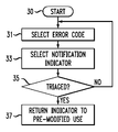
- FIG. 3 is a flow diagram describing the steps in the method.
- FIG. 4 is an exemplary block diagram of a communications network employing the method to diagnose problems.
- FIG. 1 is an exemplary side view of a car 20 .
- the figure shows a headlamp 1 at the front of the car, a horn 2 inside the car, two of four wheels 3 , dashboard 4 inside the car, and computer 6 for operating the car residing inside a trunk 5 .
- the computer 6 may not reside in the trunk, but elsewhere, such as, under one of the car seats or under the hood of the car.
- Stored program code may be used to operate each component in the car 20 , determine when a fault occurs and implement the notification of an exposed fault.
- Stored program code may also be used to correlate a later occurrence of a problem with the notification of the next occurrence of an exposed fault, and restore the indicator's behavior to its original purpose.
- the stored program code may include proprietary software or software otherwise known as “freeware or open source.”
- the stored program code may be, for example, application software, operating system software, or middleware, that controls and co-ordinates distributed systems and resides on one or more computers.
- the stored program code may be firmware and may reside in various media.
- the stored program code may reside in a hardware device, such as in a microcontroller or in flash memory.
- the stored program code can be uploaded as a binary image file to the hardware device.
- FIG. 2 shows an exemplary method of interfacing a computer to the computer 6 of car 20 .
- the troubleshooter may administer the computer 6 by interfacing a laptop or desktop computer 10 thereto, for example, by using an RS-232 or USB cable, or wirelessly by radio frequency (RF) or infrared (IR), or by using a specialized cable interface, etc.
- the laptop or desktop computer 10 has stored program code that can read information from computer 6 , download information to computer 6 , and modify stored program code in computer 6 .
- the modifications to stored program code may be performed, for example, by using a command line interface or a graphical user interface.
- the laptop or desktop computer 10 may use client software that is provided by the car manufacturer or a third party vendor to diagnose problems on the car 20 . Additionally, the laptop or desktop computer 10 may have Internet access to download information, such as, software or firmware updates from the car manufacturer, for example, via a World Wide Web portal.
- the computer 6 may allow the troubleshooter to modify stored program code in computer 6 , locally or remotely, via menus without the need for laptop or desktop computer 10 .
- an existing display within the car 20 may be used, as for example, using the LCD screen (not shown) available on the dashboard of many cars.
- the computer 6 , or laptop or desktop computer 10 has the stored program code to automatically select new faults, methods of notification, and notification patterns that can be used to triage the car's 20 problem.
- FIG. 3 is a flow diagram describing the steps of the method.
- the driver and mechanic discuss the perceived problem, which is hesitation.
- the mechanic looks at the car manufacturer's computer 6 error codes, either via the computer 6 , a shop manual, or online via the World Wide Web, to see which error code correlates most closely with hesitation.
- the mechanic sees that it may be computer error 138 : the carburetor may not be operating properly.
- the computer 6 may be menu driven or have a command line interface.
- the mechanic maybe allowed to perform one or more of the following: choose an error code from a variety of error codes, at least one indicator to modify, and a behavior pattern for the indicator.
- the mechanic selects a notification indicator.
- both may agree that turning on the dashboard lights (on dashboard 4 ) on and off a number of times (ex. three times) when computer 6 next computes error code 138 , is non-obtrusive while the car is in motion.
- the mechanic may keep the car for some amount of time, or the driver may drive the car for some amount of time, such as an hour or days, before the “hesitation” occurs again.
- the mechanic may decide to administer the car's communication system to send him a message, in any modality, such as a page, SMS text message, fax, email, or voice call when the indicator provides notification of the next occurrence of the possible problem.
- laptop or desktop computer 10 may have stored program code to reproduce the perceived problem, i.e., hesitation.
- the mechanic or driver perceives the car hesitating.
- the mechanic may ask the driver, “Did the dashboard lights turn on and off three times when you next felt the car hesitate?”
- the driver may reply, “Yes, I was watching for that and I have made that correlation.”
- the mechanic in step 35 determines that he has selected the correct error code to expose as the possible problem because the driver correlated the later occurrence of hesitation with the notification of the next occurrence of computer 6 diagnosing error code 138 .
- the mechanic has triaged the problem quickly without the need to review the car's computer error log, which may be a tedious task, thereby shortening the amount of time spent actually troubleshooting this problem and reducing the mechanic's service bill.
- the mechanic is satisfied that the problem is understood, and he returns the dashboard lights to their pre-modified use.
- the mechanic can modify the stored program code in the computer 6 to expose another error code that closely matches the symptoms. For example, the mechanic may then decide that error code 140 is also applicable, as this error code may indicate that one or more spark plugs are misfiring, and therefore decides to expose error code 140 .
- the mechanic modifies the computer 6 to turn the check engine light (on dashboard 4 ) on and off three times when the computer 6 diagnoses error code 140 . The mechanic or driver proceeds to drive the car 20 .
- the mechanic or driver makes the correlation and determines the possible cause of the hesitation is indicated by error code 140 .
- the mechanic may consider the problem is triaged in step 35 and fix the spark plug misfiring problem.
- the mechanic returns the two indicators, the dashboard light and the check engine light, to their normal operating use.
- the stored program code of computer 6 may automatically return the notification indicator to its pre-modified use without the need for the mechanic to do so. This may be the case after the hesitation is resolved and/or the computer does not compute the exposed error code anymore.
- the laptop or desktop computer 10 or computer 6 may contain stored program code to reproduce the perceived problem, intelligently select one or more faults to expose, receive input and output from the car, receive input from the mechanic, and repeat the diagnostic process until the problem is triaged.
- the mechanic may enter a perceived problem as “hesitation.”
- the stored program code may list various possible faults to expose, such as 138 or 140 .
- the mechanic or the stored program code may decide which fault to expose first. For example, the stored program code may chose to expose error code 138 first.
- the mechanic or stored program code may choose what indicator to use for notification and how to modify its behavior pattern. If the stored program code chooses the indictor, it will alert the mechanic as to its choices for indicator and behavior pattern modification.
- a feedback mechanism such as, input into desktop 10 or computer 6 , to confirm when the mechanic or driver perceives the problem to occur next.
- the feedback confirms when the mechanic or driver correlates the next occurrence of the problem with the notification of the next occurrence of the exposed fault.
- this feedback mechanism helps the stored program code to determine whether the mechanic has accurately selected the correct fault to expose in the first place. If the stored program code reproduces hesitation in the car, but the mechanic does not confirm the problem as hesitation, then the stored program code can alert the mechanic that the perceived problem was mislabeled as hesitation and that the mechanic needs further discussions with the driver to understand more about the perceived problem.
- step 35 if the mechanic indicates the mechanic did correlate the next occurrence of the perceived problem with notification of the next occurrence of the exposed fault, then the stored program code may consider the problem as having been triaged, and provide the mechanic with a list of actions to fix the perceived problem.
- step 37 if the stored program code cannot reproduce the problem or does not compute the exposed error code, the stored program code may consider the problem resolved and return the notification indicators to their original purpose.
- the notification indicator can be auditory (a beep from a car horn), visible (which includes text scrolling across a display) or sensory (Braille or a phone in vibration mode).
- an endpoint device such as a Telecommunications Device for the Deaf/TeleTYpewriter (TDD/TTY) device ( 44 shown in FIG. 4 ).
- TDD/TTY Telecommunications Device for the Deaf/TeleTYpewriter
- an event may be triggered and the notification may be transmitted to an endpoint device.
- the notification may be a message to a pager or cell phone (not shown) that is set to ring or vibrate, or a message scrolling across a display (not shown), etc., to alert the mechanic to finish their coffee break and get back to the car because the problem has recurred.
- the indicator's change in behavior can occur after the fault happens once. Alternatively, if the fault happens an administrable threshold number of times, the indicator's change in behavior may occur intermittently. In another alternative, the change in behavior may become “sticky,” that is, semi-permanent, if the fault continues to occur for some administrable number of times.
- FIG. 4 shows a block diagram of an exemplary communications network that employs the method and apparatus to diagnose voice impairment problems.
- examples of endpoint devices are analog phone 41 , facsimile 42 , modem in desktop or laptop computer 43 , Telecommunications Device for the Deaf/TeleTYpewriter (TDD/TTY) terminal 44 , digital phone 45 , IP softphone client on a laptop computer or on a handheld device, internet protocol (IP) desktop phone 46 , and phone communicating via the PSTN 48 .
- endpoint devices may also include cellular phones, wireless access points, and other handheld devices such as a Blackberry® device or a PALM® device.
- the IP softphone client on a laptop device or IP desktop phone 46 may include the stored program code to allow it to communicate via one or more VoIP signaling protocols such as H.323, Session Initiation Protocol (SIP), Media Gateway Control Protocol (MGCP), etc.
- a network device may be a router, a port board operating in a gateway or a Public Branch Exchange (PBX), etc.
- Gateways 50 and 70 convert analog data, such as voice from an analog phone 41 , data from facsimile 42 , or modem 43 , to packets of data conforming to the Internet Protocol (IP). Also, each gateway 50 and 70 includes call controller 55 , which routes voice, data, image, and video transmissions. Call controller 55 is also known as Call Server, Gatekeeper (an H.323 term), Media Gateway Controller (an H.248 term), and SIP Controller (a SIP term). Call controller 55 contains stored program code and allows connections to private and public switched telephone networks (PSTNs) 64 , Ethernet local area networks (LANs) 62 , ATM networks (not shown), and the Internet 63 .
- PSTNs public switched telephone networks
- LANs Ethernet local area networks
- ATM networks not shown
- Call controller 55 may have stored program code that uses H.323 and/or SIP, which are the two prevalent protocols used for Internet Protocol (IP) telephony.
- Real-Time Protocol (RTP) is used in both H.323 and SIP to transport the real-time application data such as voice or video.
- RFC 3550-RTP A Transport Protocol for Real-Time Applications, Schulzrinne, et. al. (July 2003), which is hereby incorporated by reference herein, describes RTP as providing “end-to-end network transport functions suitable for applications transmitting real-time data, such as audio, video, or simulation data, over multicast or unicast network services.
- RTP does not address resource reservation and does not guarantee quality-of-service for real-time services.
- the data transport is augmented by a control protocol (RTCP) to allow monitoring of the data delivery in a manner scalable to large multicast networks, and to provide minimal control and identification functionality.
- RTCP control protocol
- RTP and RTCP are designed to be independent of the underlying transport and network layers . . . . Applications typically run RTP on top of UDP to make use of its multiplexing and checksum services; both protocols contribute parts of the transport protocol functionality . . . .
- Note that RTP itself does not provide any mechanism to ensure timely delivery or provide other quality-of-service guarantees, but relies on lower-layer services to do so. It does not guarantee delivery or prevent out-of-order delivery, nor does it assume that the underlying network is reliable and delivers packets in sequence.
- RTP Real-time transport protocol
- RTCP real-time transport protocol
- RTCP RTP control protocol
- the latter aspect of RTCP may be sufficient for ‘loosely controlled’ sessions, i.e., where there is no explicit membership control and set-up, but it is not necessarily intended to support all of an application's control communication requirements. This functionality may be fully or partially subsumed by a separate session control protocol, which is beyond the scope of this document.”
- the troubleshooter can monitor the received RTP voice packets on the near end of the call.
- the troubleshooter does not need to monitor the RTCP messages regarding what the far-end of the call is experiencing. If the network equipment performs jitter computations and keeps track of packet loss, these transient faults can be exposed.
- the various embodiments make use of RTP packet timestamps, sequence numbers, and packet arrival time (the time the system thinks the packet arrived) to determine packet loss, jitter, and packets received out-of-order.
- the various embodiments do not require specialized equipment, such as, network sniffers. Instead, even the non-technical customer is able to participate and quickly correlate an exposed fault with the symptom described by the customer.
- analog device 41 - 44 that is administered on gateway 50 desires to communicate with an IP phone 46 that is administered on gateway 70
- analog line card 57 takes the analog data, digitizes the data and places it on the time division multiplex (TDM) bus 65 .
- TDM time division multiplex
- the VoIP interface card 51 takes the digital data from the TDM bus 65 and places it in the payload of at least one RTP packet.
- the call controller 55 provides the appropriate information for the packet header to route the transmission to its final destination.
- digital phone 45 that is administered on gateway 50 desires to communicate with an IP phone 46 that is administered on gateway 70
- digital line card 58 takes digital data from the digital phone 45 and places it on the TDM bus 65 .
- the call controller 55 of gateway 70 commands the VoIP interface card 51 to place the digital data from the TDM bus 65 into the payload of at least one RTP packet.
- the call controller 55 ensures that the appropriate routing information is in the packet header.
- the call controllers 55 route data between two endpoint devices, such as analog devices 41 - 44 , digital devices 45 , or IP devices 46 , within the enterprise.
- the call controllers 55 also route data from an endpoint device 48 outside of the enterprise by using the PSTN.
- an analog trunk card 59 or a digital trunk card 60 takes the communication data from the PSTN 64 and places it on the TDM bus 61 .
- the local call controller 55 commands the VoIP interface card 51 to place the media data into at least one RTP packet payload if the call is to an IP phone 46 or if the data needs to be routed to another gateway 50 via the Internet 63 .
- gateway 50 allows for conversion of the RTP packet(s) to the appropriate protocol for play-out to the appropriate endpoint device 41 - 46 .
- Packet loss is an outside impairment that potentially affects all IP terminating equipment, such as gateways 50 and 70 , or routers ( 80 ), on LAN 62 .
- IP terminating equipment such as gateways 50 and 70 , or routers ( 80 ), on LAN 62 .
- Customers and technicians often indict the enterprise IP terminating equipment.
- the various embodiments allow the customer, technician, and developers who are troubleshooting the problem to determine if the fault originated within or outside of the enterprise. Resolution of the problem is possible without the need to scour error logs 56 .
- the troubleshooter may expose faults that are already monitored by gateways 50 and 70 , which are handling the transmission of the caller who is experiencing the voice impairment.
- the troubleshooter i.e., the technician or developer, may access the administration pages (not shown) of the local call controller 55 and selects a fault, i.e., error to expose.
- a fault may be a code number, series of code numbers, a title, or a grouping of errors under one header, etc.
- Accessing the administration pages can be done locally on the device or remotely over a LAN via a centralized server that also is used to administer other network communications equipment, or remotely via a web portal and the Internet.
- the actual administration can be performed via a command line interface or a graphical user interface (GUI).
- GUI graphical user interface
- the RTP sequence number resides in the RTP packet header and is used to detect packet-loss. Normally, the RTP sequence number increments by one for every packet that is sent. Hence, the RTP sequence number of the current packet minus the RTP sequence number of the previous packet should equal one in a well-behaved network. Otherwise, the packet stream was disrupted by packet loss or jitter.
- the troubleshooter may expose error codes that additionally track QoS levels and RTP stream reset (SSRC changes).
- the out-of-order (i.e., out-of-sequence) RTP packet may be computed by the VoIP interface board 51 .
- RTP packet header time-stamp Another fault that may be exposed is an error code that tracks problems with the RTP packet header time-stamp, which corresponds to the time when the packet was sent out.
- the RTP packet header timestamp is used to detect clock drift between two systems, for example, gateways 50 and 70 . Additionally, the RTP packet header time-stamp may be used to determine a design flaw in another system's transmitter, for example, the transmitter of a router that does RTP header compression.
- exposing an error code that tracks problems with the RTP packet header time-stamp may indicate a lost packet.
- the RTP packet stream enters the enterprise communications network gateway 50 , there may be missing, i.e., lost packets due perhaps to network congestion from the Internet 63 .
- the VoIP interface board 51 At the VoIP interface board 51 , there is a buffer containing the RTP packet payloads.
- the VoIP interface board 51 controls the media play-out to the TDM bus at the regular packet rate of 64 kbps.
- the VoIP interface board 51 determines when the buffer is emptying, i.e., playing out, faster than it is being filled with payload of voice data.
- the VoIP interface board 51 must react to the missing RTP packets.
- the troubleshooter in the event of a voice impairment on a converged network, the troubleshooter discusses the problem with the end user experiencing the problem. Based on this information, the troubleshooter may suspect one or more devices on the converged network that may be the source of the problem and will modify the behavior of an indicator on at least one device to behave differently when the next occurrence of the selected fault occurs.
- the troubleshooter uses the command line interface or GUI interface, on the suspected device or via a separate network management device, to select an error code from a list of possible error codes that may be the possible cause of the problem. For example, based on the description of the problem the troubleshooter may suspect a router ( 80 shown in FIG.
- the troubleshooter may select error code 138 , which indicates out-of-sequence RTP packets.
- the troubleshooter selects an indicator and pattern from a list of possible notification indicators and possible notification patterns. For example, the troubleshooter may select one or more LEDs that are normally used to display the current call appearance line on endpoint device IP phone 46 as the notification indictor. For the notification pattern, the troubleshooter may select to flash a first LED on and off and to do so one or more times (ex. three times).
- the call controller 55 will send a control message to endpoint device IP phone 46 to flash on and off three times the selected LED that is normally used to display the current call appearance line.
- the troubleshooter may then ask the customer, “At the endpoint device, did a first LED flash on and off three times when the voice impairment next occurred?” The customer may comment, “Yes, I saw the first LED flash on and off three times when the voice impairment next occurred.”
- the troubleshooter knows that the problem was out-of-sequence RTP packets from the router 80 .
- the troubleshooter may return the LED to its original purpose.
- the call controller 55 may automatically return the notification indicator to its original purpose.
- the troubleshooter may not have selected the correct fault (i.e., possible cause of the problem) to expose and may not have selected the correct device to suspect. In this case, the troubleshooter returns to step 31 and decides to select error code 140 (ex. tracks problems with RTP packet header time-stamp) as the next fault to expose on the gateway 50 .
- the troubleshooter will select from gateway 50 administration pages a notification indictor and pattern, such as dimming the IP phone 46 LCD display several times or scrolling a message across the LCD display.
- the troubleshooter will discuss with the customer the various notification methods and select a preferred method. For this customer, it may be scrolling a message across the LCD display.
- error code 140 which indicates a lost packet
- the call controller 55 sends a control message to the endpoint device IP phone 46 to scroll a message (ex., “The gateway has diagnosed lost packets”) across the LCD display.
- step 35 either the customer may notify the troubleshooter of the voice impairment or the troubleshooter may remotely monitor the communications equipment and receive an alert, via any communications modality (ex. voice, fax, email, instant messaging, SMS text, page) that the indicator provided notification of the possible cause of the next occurrence of the problem.
- Any communications modality ex. voice, fax, email, instant messaging, SMS text, page
- Both the customer and troubleshooter may use voicemail, email, instant messaging, etc., to communicate whether the customer saw a message scrolling across the LCD display while the voice impairment was occurring. If the customer says yes, he noticed the correlation, then in step 37 the troubleshooter can stop the modified behavior of the indicators and return all indicator(s) to their original use by deselecting the exposed error code and the notification indicator.
- stored program code that is in a local or a centralized network management device, may iteratively perform the troubleshooting steps. For example, the troubleshooter may have previously directed the customer to press # on the endpoint device keypad if the LED flashed, press ## if the LED did not flash, and press #8 at the occurrence of the next voice impairment.
- step 31 the stored program code then selects the next possible fault that affects voice quality of service, such as, packet loss, which is error code 140 and determines to monitor this error code from one or more network communication devices (ex. gateway 50 and router 80 ) it is responsible to manage on the network.
- voice quality of service such as, packet loss
- the stored program code also selects another notification method to notify the customer of the next occurrence of packet loss, such as, scrolling a text message across the customer's IP phone 46 display.
- the stored program code will send a message, such as via email, instant messaging, or voice messaging, alerting the customer to look for a text message (ex. “The network is experiencing packet loss”) scrolling across the IP phone 46 display at the next occurrence of voice quality problems during an individual call or a conference call. This time, the customer is to press ##1 if the voice quality problem occurs but there are no flashing LEDs or the text message (“The network is experiencing packet loss”) does not scroll across the display.
- the customer is to press #1 when the voice quality problem occurs and the text message (“The network is experiencing packet loss”) scrolls across the LCD display.
- the customer is to press #2 when the voice quality problem occurs and the LED, normally used with a call appearance line, flashes on and off three times.
- the stored program code may copy the troubleshooter on the message sent to the customer.
- step 35 the stored program code and the troubleshooter know that the source of the problem was packet loss.
- the stored program code collected the error code information from gateway 50 and router 80 and knows which device was the device diagnosing error code 140 .
- step 37 when the triage is completed, the troubleshooter or the stored program code may return the indicators to their original use.
- Selecting notification indicators on endpoint devices is not limited to LEDs.
- the selection list of notification indicators may include existing display indicators (LCD or LED) on IP port circuits packs, such as on VoIP interface 51 or on a router 80 .
- the possible notification patterns may include the existing yellow status LED, or flashing the LED off for short periods-of-time while there is, for example, packet loss. For example, one short blink indicates small packet loss ( ⁇ X), and two short blinks indicate greater packet loss (>X).
- the patterns can be set as desired, and the thresholds for each pattern can be set to a default or be adjusted by a technician or a system administrator.
- an IP port circuit pack may continue to use a yellow LED that is lit when a call or transmission is active to keep a technician from pulling the board when there is an active call or transmission on the board.
- the selection list of notification indicators can be extended to non-IP phones, such as to analog devices 41 - 44 or digital phones 45 with existing LED or LDC displays.
- the call controller 55 can send a control message to control the display to perform any type of pattern blink on an LED, scroll any message across an LCD display, give a short ring, or give a beep on the speaker.
- the indicator's change in behavior as modified by the troubleshooter occurs after the fault happens once.
- the indicator's change in behavior may occur intermittently.
- the change in behavior may become semi-permanent if the fault continues to recur some administrable number of times.
Abstract
Description
| 91 | 96-98 Civic | Fuel Tank Pressure Sensor low input |
| 97-98 Prelude | ||
| 94+ Integra | ||
| 92 | 96-98 Civic | Evaporative Emission Control System insufficient |
| 97-98 CRV | purge flow | |
| 96-98 Prelude | ||
| 94+ Integra | ||
Claims (22)
Priority Applications (1)
| Application Number | Priority Date | Filing Date | Title |
|---|---|---|---|
| US12/049,355 US8054171B1 (en) | 2008-03-16 | 2008-03-16 | Programming an existing indicator to indicate the cause of a condition |
Applications Claiming Priority (1)
| Application Number | Priority Date | Filing Date | Title |
|---|---|---|---|
| US12/049,355 US8054171B1 (en) | 2008-03-16 | 2008-03-16 | Programming an existing indicator to indicate the cause of a condition |
Publications (1)
| Publication Number | Publication Date |
|---|---|
| US8054171B1 true US8054171B1 (en) | 2011-11-08 |
Family
ID=44882510
Family Applications (1)
| Application Number | Title | Priority Date | Filing Date |
|---|---|---|---|
| US12/049,355 Expired - Fee Related US8054171B1 (en) | 2008-03-16 | 2008-03-16 | Programming an existing indicator to indicate the cause of a condition |
Country Status (1)
| Country | Link |
|---|---|
| US (1) | US8054171B1 (en) |
Cited By (3)
| Publication number | Priority date | Publication date | Assignee | Title |
|---|---|---|---|---|
| US20140128049A1 (en) * | 2012-11-08 | 2014-05-08 | Honda Motor Co., Ltd. | Vehicular display system |
| CN108170122A (en) * | 2017-12-18 | 2018-06-15 | 北京汽车集团有限公司 | Vehicle, car fault diagnosis method and device |
| US11132173B1 (en) * | 2014-02-20 | 2021-09-28 | Amazon Technologies, Inc. | Network scheduling of stimulus-based actions |
Citations (5)
| Publication number | Priority date | Publication date | Assignee | Title |
|---|---|---|---|---|
| US3872424A (en) * | 1973-10-12 | 1975-03-18 | Goodyear Tire & Rubber | Apparatus and method for transmitting auxiliary signals on existing vehicle wiring |
| US3975708A (en) * | 1974-02-27 | 1976-08-17 | T.S.W.S., Inc. | Vehicle condition monitoring system |
| US4739309A (en) * | 1985-04-02 | 1988-04-19 | Robert Bosch Gmbh | Method and system for indicating and display information in response to electrical signals |
| US5367297A (en) * | 1990-05-29 | 1994-11-22 | Sanshin Kogyo Kabushiki Kaisha | Display system for vessel |
| US20090096597A1 (en) * | 2007-10-11 | 2009-04-16 | Avery Jr Richard M | Driver interface unit |
-
2008
- 2008-03-16 US US12/049,355 patent/US8054171B1/en not_active Expired - Fee Related
Patent Citations (5)
| Publication number | Priority date | Publication date | Assignee | Title |
|---|---|---|---|---|
| US3872424A (en) * | 1973-10-12 | 1975-03-18 | Goodyear Tire & Rubber | Apparatus and method for transmitting auxiliary signals on existing vehicle wiring |
| US3975708A (en) * | 1974-02-27 | 1976-08-17 | T.S.W.S., Inc. | Vehicle condition monitoring system |
| US4739309A (en) * | 1985-04-02 | 1988-04-19 | Robert Bosch Gmbh | Method and system for indicating and display information in response to electrical signals |
| US5367297A (en) * | 1990-05-29 | 1994-11-22 | Sanshin Kogyo Kabushiki Kaisha | Display system for vessel |
| US20090096597A1 (en) * | 2007-10-11 | 2009-04-16 | Avery Jr Richard M | Driver interface unit |
Cited By (4)
| Publication number | Priority date | Publication date | Assignee | Title |
|---|---|---|---|---|
| US20140128049A1 (en) * | 2012-11-08 | 2014-05-08 | Honda Motor Co., Ltd. | Vehicular display system |
| US11132173B1 (en) * | 2014-02-20 | 2021-09-28 | Amazon Technologies, Inc. | Network scheduling of stimulus-based actions |
| CN108170122A (en) * | 2017-12-18 | 2018-06-15 | 北京汽车集团有限公司 | Vehicle, car fault diagnosis method and device |
| CN108170122B (en) * | 2017-12-18 | 2023-09-08 | 北京汽车集团有限公司 | Vehicle, vehicle fault diagnosis method and device |
Similar Documents
| Publication | Publication Date | Title |
|---|---|---|
| US7573825B2 (en) | Methods, apparatus and computer program products for testing a voice over Internet protocol communication system | |
| CA2712002C (en) | Diagnostics methods for a communications device | |
| CN103069775B (en) | Calling re-establishes | |
| US7231210B1 (en) | Method and apparatus for automatically generating call flow test scripts | |
| US7979496B2 (en) | Method and apparatus for measuring health and performance of a messaging system | |
| US8594278B2 (en) | Test system for voice communications systems | |
| US9438724B2 (en) | Notification and troubleshooting of interruptions, failures, and updates | |
| US9369229B2 (en) | Communications device | |
| US9172601B2 (en) | Communications links | |
| US8363557B2 (en) | Methods, systems, and computer readable media for remotely evaluating and controlling voice over IP (VoIP) subscriber terminal equipment | |
| EP3799406A1 (en) | Method, system, and device for cloud voice quality monitoring | |
| CN102571421A (en) | Method and device for detecting service quality of IP access network | |
| US10554481B2 (en) | Method, device and system for detecting a quality of service problem | |
| US8054171B1 (en) | Programming an existing indicator to indicate the cause of a condition | |
| US7697512B1 (en) | Proactive monitoring of status of voice-over-IP servers | |
| US20080159513A1 (en) | System and method for providing automatic alerts of network availability to a fixed communication device | |
| EP1804479A1 (en) | System, device and method for operation and maintenance of network devices by analysis of CDRs | |
| US8687502B2 (en) | Method and apparatus for enabling auto-ticketing for endpoint devices | |
| US20050102409A1 (en) | Configuration for monitoring the state of components in a packet-switched communications network | |
| US6480576B1 (en) | Method and device for detecting path faults in a network | |
| McDaniel | CCVP TUC Quick Reference Sheets | |
| KR100624685B1 (en) | Apparatus and method for detecting network interface status in switching system | |
| EP2449746A1 (en) | Supervision of communication quality in telecommunication network gateway | |
| KR20040017408A (en) | Method of VoIP gateway call connecting with network quality |
Legal Events
| Date | Code | Title | Description |
|---|---|---|---|
| AS | Assignment |
Owner name: AVAYA TECHNOLOGY LLC, NEW JERSEY Free format text: ASSIGNMENT OF ASSIGNORS INTEREST;ASSIGNORS:LANZAFAME, CHRISTOPHER;MORAN, CHRISTOPHER;SZAJDECKI, RICHARD;REEL/FRAME:020657/0429 Effective date: 20080304 |
|
| AS | Assignment |
Owner name: AVAYA INC, NEW JERSEY Free format text: REASSIGNMENT;ASSIGNOR:AVAYA TECHNOLOGY LLC;REEL/FRAME:021156/0734 Effective date: 20080625 |
|
| FEPP | Fee payment procedure |
Free format text: PAYOR NUMBER ASSIGNED (ORIGINAL EVENT CODE: ASPN); ENTITY STATUS OF PATENT OWNER: LARGE ENTITY |
|
| AS | Assignment |
Owner name: BANK OF NEW YORK MELLON TRUST, NA, AS NOTES COLLAT Free format text: SECURITY AGREEMENT;ASSIGNOR:AVAYA INC., A DELAWARE CORPORATION;REEL/FRAME:025863/0535 Effective date: 20110211 Owner name: BANK OF NEW YORK MELLON TRUST, NA, AS NOTES COLLATERAL AGENT, THE, PENNSYLVANIA Free format text: SECURITY AGREEMENT;ASSIGNOR:AVAYA INC., A DELAWARE CORPORATION;REEL/FRAME:025863/0535 Effective date: 20110211 |
|
| ZAAA | Notice of allowance and fees due |
Free format text: ORIGINAL CODE: NOA |
|
| ZAAB | Notice of allowance mailed |
Free format text: ORIGINAL CODE: MN/=. |
|
| STCF | Information on status: patent grant |
Free format text: PATENTED CASE |
|
| AS | Assignment |
Owner name: BANK OF NEW YORK MELLON TRUST COMPANY, N.A., THE, PENNSYLVANIA Free format text: SECURITY AGREEMENT;ASSIGNOR:AVAYA, INC.;REEL/FRAME:030083/0639 Effective date: 20130307 Owner name: BANK OF NEW YORK MELLON TRUST COMPANY, N.A., THE, Free format text: SECURITY AGREEMENT;ASSIGNOR:AVAYA, INC.;REEL/FRAME:030083/0639 Effective date: 20130307 |
|
| FPAY | Fee payment |
Year of fee payment: 4 |
|
| AS | Assignment |
Owner name: CITIBANK, N.A., AS ADMINISTRATIVE AGENT, NEW YORK Free format text: SECURITY INTEREST;ASSIGNORS:AVAYA INC.;AVAYA INTEGRATED CABINET SOLUTIONS INC.;OCTEL COMMUNICATIONS CORPORATION;AND OTHERS;REEL/FRAME:041576/0001 Effective date: 20170124 |
|
| AS | Assignment |
Owner name: OCTEL COMMUNICATIONS LLC (FORMERLY KNOWN AS OCTEL COMMUNICATIONS CORPORATION), CALIFORNIA Free format text: BANKRUPTCY COURT ORDER RELEASING ALL LIENS INCLUDING THE SECURITY INTEREST RECORDED AT REEL/FRAME 041576/0001;ASSIGNOR:CITIBANK, N.A.;REEL/FRAME:044893/0531 Effective date: 20171128 Owner name: AVAYA INTEGRATED CABINET SOLUTIONS INC., CALIFORNIA Free format text: BANKRUPTCY COURT ORDER RELEASING ALL LIENS INCLUDING THE SECURITY INTEREST RECORDED AT REEL/FRAME 041576/0001;ASSIGNOR:CITIBANK, N.A.;REEL/FRAME:044893/0531 Effective date: 20171128 Owner name: AVAYA INC., CALIFORNIA Free format text: BANKRUPTCY COURT ORDER RELEASING ALL LIENS INCLUDING THE SECURITY INTEREST RECORDED AT REEL/FRAME 025863/0535;ASSIGNOR:THE BANK OF NEW YORK MELLON TRUST, NA;REEL/FRAME:044892/0001 Effective date: 20171128 Owner name: AVAYA INC., CALIFORNIA Free format text: BANKRUPTCY COURT ORDER RELEASING ALL LIENS INCLUDING THE SECURITY INTEREST RECORDED AT REEL/FRAME 041576/0001;ASSIGNOR:CITIBANK, N.A.;REEL/FRAME:044893/0531 Effective date: 20171128 Owner name: AVAYA INTEGRATED CABINET SOLUTIONS INC., CALIFORNI Free format text: BANKRUPTCY COURT ORDER RELEASING ALL LIENS INCLUDING THE SECURITY INTEREST RECORDED AT REEL/FRAME 041576/0001;ASSIGNOR:CITIBANK, N.A.;REEL/FRAME:044893/0531 Effective date: 20171128 Owner name: VPNET TECHNOLOGIES, INC., CALIFORNIA Free format text: BANKRUPTCY COURT ORDER RELEASING ALL LIENS INCLUDING THE SECURITY INTEREST RECORDED AT REEL/FRAME 041576/0001;ASSIGNOR:CITIBANK, N.A.;REEL/FRAME:044893/0531 Effective date: 20171128 Owner name: OCTEL COMMUNICATIONS LLC (FORMERLY KNOWN AS OCTEL Free format text: BANKRUPTCY COURT ORDER RELEASING ALL LIENS INCLUDING THE SECURITY INTEREST RECORDED AT REEL/FRAME 041576/0001;ASSIGNOR:CITIBANK, N.A.;REEL/FRAME:044893/0531 Effective date: 20171128 Owner name: AVAYA INC., CALIFORNIA Free format text: BANKRUPTCY COURT ORDER RELEASING ALL LIENS INCLUDING THE SECURITY INTEREST RECORDED AT REEL/FRAME 030083/0639;ASSIGNOR:THE BANK OF NEW YORK MELLON TRUST COMPANY, N.A.;REEL/FRAME:045012/0666 Effective date: 20171128 |
|
| AS | Assignment |
Owner name: GOLDMAN SACHS BANK USA, AS COLLATERAL AGENT, NEW YORK Free format text: SECURITY INTEREST;ASSIGNORS:AVAYA INC.;AVAYA INTEGRATED CABINET SOLUTIONS LLC;OCTEL COMMUNICATIONS LLC;AND OTHERS;REEL/FRAME:045034/0001 Effective date: 20171215 Owner name: GOLDMAN SACHS BANK USA, AS COLLATERAL AGENT, NEW Y Free format text: SECURITY INTEREST;ASSIGNORS:AVAYA INC.;AVAYA INTEGRATED CABINET SOLUTIONS LLC;OCTEL COMMUNICATIONS LLC;AND OTHERS;REEL/FRAME:045034/0001 Effective date: 20171215 |
|
| AS | Assignment |
Owner name: CITIBANK, N.A., AS COLLATERAL AGENT, NEW YORK Free format text: SECURITY INTEREST;ASSIGNORS:AVAYA INC.;AVAYA INTEGRATED CABINET SOLUTIONS LLC;OCTEL COMMUNICATIONS LLC;AND OTHERS;REEL/FRAME:045124/0026 Effective date: 20171215 |
|
| MAFP | Maintenance fee payment |
Free format text: PAYMENT OF MAINTENANCE FEE, 8TH YEAR, LARGE ENTITY (ORIGINAL EVENT CODE: M1552); ENTITY STATUS OF PATENT OWNER: LARGE ENTITY Year of fee payment: 8 |
|
| AS | Assignment |
Owner name: WILMINGTON TRUST, NATIONAL ASSOCIATION, MINNESOTA Free format text: SECURITY INTEREST;ASSIGNORS:AVAYA INC.;AVAYA MANAGEMENT L.P.;INTELLISIST, INC.;AND OTHERS;REEL/FRAME:053955/0436 Effective date: 20200925 |
|
| AS | Assignment |
Owner name: WILMINGTON TRUST, NATIONAL ASSOCIATION, AS COLLATERAL AGENT, DELAWARE Free format text: INTELLECTUAL PROPERTY SECURITY AGREEMENT;ASSIGNORS:AVAYA INC.;INTELLISIST, INC.;AVAYA MANAGEMENT L.P.;AND OTHERS;REEL/FRAME:061087/0386 Effective date: 20220712 |
|
| AS | Assignment |
Owner name: AVAYA INTEGRATED CABINET SOLUTIONS LLC, NEW JERSEY Free format text: RELEASE OF SECURITY INTEREST IN PATENTS AT REEL 45124/FRAME 0026;ASSIGNOR:CITIBANK, N.A., AS COLLATERAL AGENT;REEL/FRAME:063457/0001 Effective date: 20230403 Owner name: AVAYA MANAGEMENT L.P., NEW JERSEY Free format text: RELEASE OF SECURITY INTEREST IN PATENTS AT REEL 45124/FRAME 0026;ASSIGNOR:CITIBANK, N.A., AS COLLATERAL AGENT;REEL/FRAME:063457/0001 Effective date: 20230403 Owner name: AVAYA INC., NEW JERSEY Free format text: RELEASE OF SECURITY INTEREST IN PATENTS AT REEL 45124/FRAME 0026;ASSIGNOR:CITIBANK, N.A., AS COLLATERAL AGENT;REEL/FRAME:063457/0001 Effective date: 20230403 Owner name: AVAYA HOLDINGS CORP., NEW JERSEY Free format text: RELEASE OF SECURITY INTEREST IN PATENTS AT REEL 45124/FRAME 0026;ASSIGNOR:CITIBANK, N.A., AS COLLATERAL AGENT;REEL/FRAME:063457/0001 Effective date: 20230403 |
|
| AS | Assignment |
Owner name: WILMINGTON SAVINGS FUND SOCIETY, FSB (COLLATERAL AGENT), DELAWARE Free format text: INTELLECTUAL PROPERTY SECURITY AGREEMENT;ASSIGNORS:AVAYA MANAGEMENT L.P.;AVAYA INC.;INTELLISIST, INC.;AND OTHERS;REEL/FRAME:063742/0001 Effective date: 20230501 |
|
| AS | Assignment |
Owner name: CITIBANK, N.A., AS COLLATERAL AGENT, NEW YORK Free format text: INTELLECTUAL PROPERTY SECURITY AGREEMENT;ASSIGNORS:AVAYA INC.;AVAYA MANAGEMENT L.P.;INTELLISIST, INC.;REEL/FRAME:063542/0662 Effective date: 20230501 |
|
| AS | Assignment |
Owner name: AVAYA MANAGEMENT L.P., NEW JERSEY Free format text: RELEASE OF SECURITY INTEREST IN PATENTS (REEL/FRAME 045034/0001);ASSIGNOR:GOLDMAN SACHS BANK USA., AS COLLATERAL AGENT;REEL/FRAME:063779/0622 Effective date: 20230501 Owner name: CAAS TECHNOLOGIES, LLC, NEW JERSEY Free format text: RELEASE OF SECURITY INTEREST IN PATENTS (REEL/FRAME 045034/0001);ASSIGNOR:GOLDMAN SACHS BANK USA., AS COLLATERAL AGENT;REEL/FRAME:063779/0622 Effective date: 20230501 Owner name: HYPERQUALITY II, LLC, NEW JERSEY Free format text: RELEASE OF SECURITY INTEREST IN PATENTS (REEL/FRAME 045034/0001);ASSIGNOR:GOLDMAN SACHS BANK USA., AS COLLATERAL AGENT;REEL/FRAME:063779/0622 Effective date: 20230501 Owner name: HYPERQUALITY, INC., NEW JERSEY Free format text: RELEASE OF SECURITY INTEREST IN PATENTS (REEL/FRAME 045034/0001);ASSIGNOR:GOLDMAN SACHS BANK USA., AS COLLATERAL AGENT;REEL/FRAME:063779/0622 Effective date: 20230501 Owner name: ZANG, INC. (FORMER NAME OF AVAYA CLOUD INC.), NEW JERSEY Free format text: RELEASE OF SECURITY INTEREST IN PATENTS (REEL/FRAME 045034/0001);ASSIGNOR:GOLDMAN SACHS BANK USA., AS COLLATERAL AGENT;REEL/FRAME:063779/0622 Effective date: 20230501 Owner name: VPNET TECHNOLOGIES, INC., NEW JERSEY Free format text: RELEASE OF SECURITY INTEREST IN PATENTS (REEL/FRAME 045034/0001);ASSIGNOR:GOLDMAN SACHS BANK USA., AS COLLATERAL AGENT;REEL/FRAME:063779/0622 Effective date: 20230501 Owner name: OCTEL COMMUNICATIONS LLC, NEW JERSEY Free format text: RELEASE OF SECURITY INTEREST IN PATENTS (REEL/FRAME 045034/0001);ASSIGNOR:GOLDMAN SACHS BANK USA., AS COLLATERAL AGENT;REEL/FRAME:063779/0622 Effective date: 20230501 Owner name: AVAYA INTEGRATED CABINET SOLUTIONS LLC, NEW JERSEY Free format text: RELEASE OF SECURITY INTEREST IN PATENTS (REEL/FRAME 045034/0001);ASSIGNOR:GOLDMAN SACHS BANK USA., AS COLLATERAL AGENT;REEL/FRAME:063779/0622 Effective date: 20230501 Owner name: INTELLISIST, INC., NEW JERSEY Free format text: RELEASE OF SECURITY INTEREST IN PATENTS (REEL/FRAME 045034/0001);ASSIGNOR:GOLDMAN SACHS BANK USA., AS COLLATERAL AGENT;REEL/FRAME:063779/0622 Effective date: 20230501 Owner name: AVAYA INC., NEW JERSEY Free format text: RELEASE OF SECURITY INTEREST IN PATENTS (REEL/FRAME 045034/0001);ASSIGNOR:GOLDMAN SACHS BANK USA., AS COLLATERAL AGENT;REEL/FRAME:063779/0622 Effective date: 20230501 Owner name: AVAYA INTEGRATED CABINET SOLUTIONS LLC, NEW JERSEY Free format text: RELEASE OF SECURITY INTEREST IN PATENTS (REEL/FRAME 53955/0436);ASSIGNOR:WILMINGTON TRUST, NATIONAL ASSOCIATION, AS NOTES COLLATERAL AGENT;REEL/FRAME:063705/0023 Effective date: 20230501 Owner name: INTELLISIST, INC., NEW JERSEY Free format text: RELEASE OF SECURITY INTEREST IN PATENTS (REEL/FRAME 53955/0436);ASSIGNOR:WILMINGTON TRUST, NATIONAL ASSOCIATION, AS NOTES COLLATERAL AGENT;REEL/FRAME:063705/0023 Effective date: 20230501 Owner name: AVAYA INC., NEW JERSEY Free format text: RELEASE OF SECURITY INTEREST IN PATENTS (REEL/FRAME 53955/0436);ASSIGNOR:WILMINGTON TRUST, NATIONAL ASSOCIATION, AS NOTES COLLATERAL AGENT;REEL/FRAME:063705/0023 Effective date: 20230501 Owner name: AVAYA MANAGEMENT L.P., NEW JERSEY Free format text: RELEASE OF SECURITY INTEREST IN PATENTS (REEL/FRAME 53955/0436);ASSIGNOR:WILMINGTON TRUST, NATIONAL ASSOCIATION, AS NOTES COLLATERAL AGENT;REEL/FRAME:063705/0023 Effective date: 20230501 Owner name: AVAYA INTEGRATED CABINET SOLUTIONS LLC, NEW JERSEY Free format text: RELEASE OF SECURITY INTEREST IN PATENTS (REEL/FRAME 61087/0386);ASSIGNOR:WILMINGTON TRUST, NATIONAL ASSOCIATION, AS NOTES COLLATERAL AGENT;REEL/FRAME:063690/0359 Effective date: 20230501 Owner name: INTELLISIST, INC., NEW JERSEY Free format text: RELEASE OF SECURITY INTEREST IN PATENTS (REEL/FRAME 61087/0386);ASSIGNOR:WILMINGTON TRUST, NATIONAL ASSOCIATION, AS NOTES COLLATERAL AGENT;REEL/FRAME:063690/0359 Effective date: 20230501 Owner name: AVAYA INC., NEW JERSEY Free format text: RELEASE OF SECURITY INTEREST IN PATENTS (REEL/FRAME 61087/0386);ASSIGNOR:WILMINGTON TRUST, NATIONAL ASSOCIATION, AS NOTES COLLATERAL AGENT;REEL/FRAME:063690/0359 Effective date: 20230501 Owner name: AVAYA MANAGEMENT L.P., NEW JERSEY Free format text: RELEASE OF SECURITY INTEREST IN PATENTS (REEL/FRAME 61087/0386);ASSIGNOR:WILMINGTON TRUST, NATIONAL ASSOCIATION, AS NOTES COLLATERAL AGENT;REEL/FRAME:063690/0359 Effective date: 20230501 |
|
| FEPP | Fee payment procedure |
Free format text: MAINTENANCE FEE REMINDER MAILED (ORIGINAL EVENT CODE: REM.); ENTITY STATUS OF PATENT OWNER: LARGE ENTITY |
|
| AS | Assignment |
Owner name: AVAYA LLC, DELAWARE Free format text: (SECURITY INTEREST) GRANTOR'S NAME CHANGE;ASSIGNOR:AVAYA INC.;REEL/FRAME:065019/0231 Effective date: 20230501 |
|
| LAPS | Lapse for failure to pay maintenance fees |
Free format text: PATENT EXPIRED FOR FAILURE TO PAY MAINTENANCE FEES (ORIGINAL EVENT CODE: EXP.); ENTITY STATUS OF PATENT OWNER: LARGE ENTITY |
|
| STCH | Information on status: patent discontinuation |
Free format text: PATENT EXPIRED DUE TO NONPAYMENT OF MAINTENANCE FEES UNDER 37 CFR 1.362 |
|
| FP | Lapsed due to failure to pay maintenance fee |
Effective date: 20231108 |