US8040879B1 - Communication system - Google Patents
Communication system Download PDFInfo
- Publication number
- US8040879B1 US8040879B1 US10/088,682 US8868200A US8040879B1 US 8040879 B1 US8040879 B1 US 8040879B1 US 8868200 A US8868200 A US 8868200A US 8040879 B1 US8040879 B1 US 8040879B1
- Authority
- US
- United States
- Prior art keywords
- communications
- connection
- local
- network
- transport network
- Prior art date
- Legal status (The legal status is an assumption and is not a legal conclusion. Google has not performed a legal analysis and makes no representation as to the accuracy of the status listed.)
- Expired - Fee Related, expires
Links
- 238000004891 communication Methods 0.000 title claims abstract description 120
- 238000000034 method Methods 0.000 claims abstract description 29
- 238000006243 chemical reaction Methods 0.000 claims description 35
- 239000011159 matrix material Substances 0.000 claims description 9
- 230000000295 complement effect Effects 0.000 claims description 5
- 230000005540 biological transmission Effects 0.000 claims description 3
- 239000002609 medium Substances 0.000 claims description 3
- 239000006163 transport media Substances 0.000 claims description 3
- 238000011156 evaluation Methods 0.000 claims 1
- 238000000926 separation method Methods 0.000 claims 1
- 230000007246 mechanism Effects 0.000 abstract description 19
- 230000032258 transport Effects 0.000 description 49
- 230000008901 benefit Effects 0.000 description 12
- 238000012545 processing Methods 0.000 description 12
- 230000011664 signaling Effects 0.000 description 10
- 230000002093 peripheral effect Effects 0.000 description 9
- 238000009434 installation Methods 0.000 description 7
- 101000730673 Homo sapiens PRELI domain containing protein 3A Proteins 0.000 description 6
- 102100032984 PRELI domain containing protein 3A Human genes 0.000 description 6
- 101001074395 Homo sapiens PRELI domain containing protein 3B Proteins 0.000 description 5
- 102100036156 PRELI domain containing protein 3B Human genes 0.000 description 5
- 230000006870 function Effects 0.000 description 5
- 239000013256 coordination polymer Substances 0.000 description 4
- 230000001419 dependent effect Effects 0.000 description 4
- 238000011161 development Methods 0.000 description 4
- 230000018109 developmental process Effects 0.000 description 4
- 238000013500 data storage Methods 0.000 description 2
- 230000010354 integration Effects 0.000 description 2
- 238000013507 mapping Methods 0.000 description 2
- 230000000630 rising effect Effects 0.000 description 2
- 230000008859 change Effects 0.000 description 1
- 230000001143 conditioned effect Effects 0.000 description 1
- 238000013461 design Methods 0.000 description 1
- 239000000835 fiber Substances 0.000 description 1
- 238000012423 maintenance Methods 0.000 description 1
- 230000014759 maintenance of location Effects 0.000 description 1
- 239000000203 mixture Substances 0.000 description 1
- 230000003287 optical effect Effects 0.000 description 1
- 101150010006 slmo gene Proteins 0.000 description 1
- 238000012546 transfer Methods 0.000 description 1
- 230000001960 triggered effect Effects 0.000 description 1
Images


Classifications
-
- H—ELECTRICITY
- H04—ELECTRIC COMMUNICATION TECHNIQUE
- H04Q—SELECTING
- H04Q11/00—Selecting arrangements for multiplex systems
- H04Q11/04—Selecting arrangements for multiplex systems for time-division multiplexing
- H04Q11/0407—Selecting arrangements for multiplex systems for time-division multiplexing using a stored programme control
-
- H—ELECTRICITY
- H04—ELECTRIC COMMUNICATION TECHNIQUE
- H04Q—SELECTING
- H04Q2213/00—Indexing scheme relating to selecting arrangements in general and for multiplex systems
- H04Q2213/1302—Relay switches
-
- H—ELECTRICITY
- H04—ELECTRIC COMMUNICATION TECHNIQUE
- H04Q—SELECTING
- H04Q2213/00—Indexing scheme relating to selecting arrangements in general and for multiplex systems
- H04Q2213/13034—A/D conversion, code compression/expansion
-
- H—ELECTRICITY
- H04—ELECTRIC COMMUNICATION TECHNIQUE
- H04Q—SELECTING
- H04Q2213/00—Indexing scheme relating to selecting arrangements in general and for multiplex systems
- H04Q2213/1304—Coordinate switches, crossbar, 4/2 with relays, coupling field
-
- H—ELECTRICITY
- H04—ELECTRIC COMMUNICATION TECHNIQUE
- H04Q—SELECTING
- H04Q2213/00—Indexing scheme relating to selecting arrangements in general and for multiplex systems
- H04Q2213/13104—Central control, computer control
-
- H—ELECTRICITY
- H04—ELECTRIC COMMUNICATION TECHNIQUE
- H04Q—SELECTING
- H04Q2213/00—Indexing scheme relating to selecting arrangements in general and for multiplex systems
- H04Q2213/13167—Redundant apparatus
-
- H—ELECTRICITY
- H04—ELECTRIC COMMUNICATION TECHNIQUE
- H04Q—SELECTING
- H04Q2213/00—Indexing scheme relating to selecting arrangements in general and for multiplex systems
- H04Q2213/13196—Connection circuit/link/trunk/junction, bridge, router, gateway
-
- H—ELECTRICITY
- H04—ELECTRIC COMMUNICATION TECHNIQUE
- H04Q—SELECTING
- H04Q2213/00—Indexing scheme relating to selecting arrangements in general and for multiplex systems
- H04Q2213/13204—Protocols
-
- H—ELECTRICITY
- H04—ELECTRIC COMMUNICATION TECHNIQUE
- H04Q—SELECTING
- H04Q2213/00—Indexing scheme relating to selecting arrangements in general and for multiplex systems
- H04Q2213/1322—PBX
-
- H—ELECTRICITY
- H04—ELECTRIC COMMUNICATION TECHNIQUE
- H04Q—SELECTING
- H04Q2213/00—Indexing scheme relating to selecting arrangements in general and for multiplex systems
- H04Q2213/1329—Asynchronous transfer mode, ATM
-
- H—ELECTRICITY
- H04—ELECTRIC COMMUNICATION TECHNIQUE
- H04Q—SELECTING
- H04Q2213/00—Indexing scheme relating to selecting arrangements in general and for multiplex systems
- H04Q2213/13292—Time division multiplexing, TDM
-
- H—ELECTRICITY
- H04—ELECTRIC COMMUNICATION TECHNIQUE
- H04Q—SELECTING
- H04Q2213/00—Indexing scheme relating to selecting arrangements in general and for multiplex systems
- H04Q2213/1338—Inter-exchange connection
-
- H—ELECTRICITY
- H04—ELECTRIC COMMUNICATION TECHNIQUE
- H04Q—SELECTING
- H04Q2213/00—Indexing scheme relating to selecting arrangements in general and for multiplex systems
- H04Q2213/13389—LAN, internet
Definitions
- the invention relates to a method and an arrangement for setting up and clearing down, and sustaining, communications links, and in particular, within the context of a private branch exchange and terminals which are to be connected.
- the rising volume of communication places greater and greater demands on switching centers, in particular on private branch exchanges, with regard to the volume of data to be transmitted for each communications link and the number of communications terminals which are to be connected to one another.
- Current devices are based, by way of example, on the TDM method (Time Division Multiplexing), in which communications data on different connections are transmitted in respectively defined timeslots.
- a connection between different communication parties is set up by a switching matrix which assigns incoming timeslots on an incoming connection outgoing timeslots to an outgoing connection on the basis of a control information item.
- switching matrices are generally of fixed proportions and can set up only a defined number of connections, which often makes it difficult to match exchanges to requirements.
- Another problem with such devices is that the timeslots are able to hold only a limited amount of data.
- FIG. 1 shows an example of a known private branch exchange 150 with two peripheral devices P 1 and P 2 to which a communications terminal KE 1 and KE 2 operating on a digital or analog basis is respectively connected.
- peripheral devices P 1 and P 2 are accommodated in the same physical area as the central device ZE 1 . By way of example, they are in the same room or in the same cabinet as it.
- the terminals occupy defined timeslots in the PCM data stream (Pulse Code Modulation) with communication data.
- the digital or analog communications terminals KE 1 and KE 2 are respectively connected to subscriber line modules SLMO 1 and SLMO 2 which supply or take digital data, intended for the respective terminals or coming from the respective terminals, to/from the PCM data stream using timeslots stipulated by signaling.
- PCM data streams are denoted by 100 and 200 in FIG. 1 .
- signaling connections are shown which are represented by 110 and 210. It should be noted that these involve a logical representation and not a physical representation. In reality, however, the transport data and the signaling data are transmitted in the same connecting cable.
- This figure also shows peripheral devices P 1 and P 2 and supply modules LTUC 1 and LTUC 2 which regulate the data traffic to the subscriber line modules of the respective peripheral devices.
- the peripheral device P 1 is supplied with signaling data via the line 110
- the peripheral device P 2 is supplied with signaling data via the signaling line 210 .
- this arrangement involves both the information to be transported and the signaling information being supplied to a central device ZE 1 .
- a messaging device DCL collects and distributes messages 2 which are interchanged between the central device ZE 1 and the peripheral devices P 1 , P 2 .
- the call processing section CP controls the setup and clear-down of connections and, to this end, uses equipment-specific interface functions DH, inter alia, which are in the form of program modules, for example.
- the invention specifies a method and an arrangement for providing a communications link which ensure a high level of flexibility in terms of matching to network infrastructures and in terms of the physical extent thereof.
- One advantage of the invention is the operation of a heterogeneous communications network using a joint control mechanism, because information about the type of protocol which can be used to reach respective subscribers is held in the area of the central control mechanism, or in the transport network.
- the topology of the transport network can differ from that of the control network in this context. This makes it possible to set up a communications link while avoiding numerous diverse conversion procedures which would be necessary on a previously stipulated path between the subscribers.
- This advantageously takes account of the fact that the subscribers communicate using different communications protocols, with local matching to the required communications protocol, as opposed to central matching, allowing the communications path to be routed via a minimal number of conversion devices, which protects the resources in the network and keeps down the length of the communications paths in the transport network.
- the method described provides not only the protocol information item but also a media information item relating to the transport network, because this makes it possible to take into account the characteristic of different transmission media in terms of transport quality, utilization and speed when controlling the connection setup.
- the method described allows the different protocol structure of communications protocols handled on a single medium or on different media to be taken into account by actuating suitable protocol conversion units, associated with communications subscribers which are involved, in an appropriately defined manner when setting up and sustaining the connection.
- the method described allows a defined media access device to be actuated for a particular communications subscriber. If a plurality of transport media are available for each communications subscriber, this advantageously allows them to be specifically taken into account and actuated when a connection is set up.
- the method described allows the information required for controlling the transport network to be set up and/or provided centrally, because the problem of updating, maintaining and saving these data is then limited to the maintenance of a central database.
- one aspect of the method described affords the opportunity for required control information to be provided locally in the transport network and for the control mechanism to request it when a connection is set up, because this allows local measures for aligning the transport network to be taken without such measures affecting the entire transport network and a central control mechanism.
- a local device is controlled by assigning to an IP address precisely one PCM data-stream subscriber line and an entire local device, because this allows IP subscribers to be managed and controlled using control mechanisms which likewise actuate TDM-based communications devices, without the additional need for a high level of development complexity in order to match these devices to IP-based terminals.
- This allows existing conventional telephone installations also to be used for IP telephony, for example, where conventional telephone installations provide a large quantity of service features, or else makes it possible to control data links to a telephone installation and thus to enhance them with service features.
- One advantage of the method described is that the setup of a direct connection between communications terminals relieves the burden on transport-network-specific devices, such as the local switching centers and the conversion devices required for the otherwise necessary data conversion. This makes it possible to increase the performance of the transport network.
- an arrangement for setting up/clearing down and/or sustaining a communications link has means which output at least two control information items to two local devices in the transport network if at least one connection element between these local devices is affected, because this provides a configuration for controlling heterogeneous transport networks which involves transmitting connection information, which is suitable for controlling TDM links, together with the required protocol information item to the local devices affected by the connection setup/clear-down and/or sustenance.
- one such arrangement likewise allows operation of a mixed infrastructure comprising TDM-based switching centers and IP-based local area networks.
- an arrangement having a central control device which provides transport-network-specific media information or protocol information and makes it available for connection setup. This ensures, in connection with an existing TDM-based communications infrastructure, that the available central database, possibly service feature implementation and application interface, can continue to be used and need be extended only by the protocol- and media-specific information for operating mixed infrastructures.
- a gateway for converting a TDM protocol into the Internet Protocol because such a gateway can connect TDM-based units to a transport network on which the Internet Protocol is handled.
- a checking device for checking protocol-specific information for the address of a local device, because this makes it possible to ensure that there is no need for a procedure for converting the communication data into transport-network-specific communication data for communications links between communications terminals associated with a single local device.
- an internal connection is set up, in one embodiment of the arrangement described, by interchanging the reading and writing directions of timeslots in a TDM data stream, because this allows a communications link to be produced within a local device in a technically most simple manner.
- one embodiment of the arrangement described has an Ethernet access facility, because such a network access facility allows a terminal to access the Ethernet.
- Such network access cards are available on the market and are a simple and inexpensive solution for producing mixed transport networks with connection elements via the Ethernet.
- the devices provided for heterogeneous network operation in local devices are incorporated in specific terminals, because such a terminal can be controlled by a TDM-based control mechanism, customary to date, with equipment-specific stipulation of a single TDM data stream in connection with a single subscriber line and a subscriber line module without any great complexity for aligning control mechanism customary to date.
- telephones and personal computers are provided as terminals, because these are the terminals which are used most frequently and direct connection of these units to the Ethernet for voice communication represents great additional benefit for terminal users if they can be operated by a central control mechanism in conjunction with conventional devices.
- FIG. 1 shows a conventional communications arrangement.
- FIG. 2 shows an example of a novel communications arrangement.
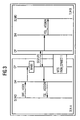
- FIG. 3 shows an example of a message flow in a known switching system.
- FIG. 4 shows an example of a message flow using timeslot-based connection information for the transport network.
- FIG. 5 shows a communications infrastructure in which different communications protocols are used on connection element links.
- FIG. 6 shows a communications infrastructure using IP-based terminals.
- FIG. 7 shows another exemplary embodiment.
- FIG. 2 shows an example of a flexible arrangement for setting up communications links.
- this arrangement illustrates the structure of a private branch exchange 250 .
- the digital or analog communications terminals KE 1 and KE 2 are in this case shown such that they are respectively connected to subscriber line modules SLMO 1 and SLMO 2 .
- such an arrangement 250 can also involve and incorporate terminals which can be connected to the transport network 700 directly, with bypassing or without an SLMO.
- FIG. 5 One example of a possible hybrid configuration is shown in FIG. 5 and is explained in the associated part of the description.
- Directly connected terminals are shown in FIG. 6 and are described by the associated part of the description of the figures.
- the local devices DZ 1 and DZ 2 each have local switching centers CS 1 and CS 2 which, by way of example, can be in the form of Ethernet or ATM access devices.
- gateways and routers and also media of any type can be connected to one another as required.
- the illustration likewise shows that the switching matrix MTS 0 is no longer used for connection tasks. Instead, the transport network performs the connection tasks.
- control lines 410 and 310 are used to provide at least one respective control information item for the respective local switching centers CS 1 and CS 2 for the purposes of setting up the communications link, the control information item being derived from a timeslot-based control information item.
- the information is interchanged using messages.
- PCM data are converted into cell data according to the standard of the transport network type 700 , such as ATM cell data, on a data link 300 or 400 .
- transport network type 700 such as ATM cell data
- Ethernet networks, other IP connections or even TDM connections are likewise suitable.
- the selection is dependent on the intended purpose of use and extends to the whole range of available networks and also optical media, both in the narrowband range and in the broadband range.
- gateways secure the link between the various network sections.
- the local switching centers CS 1 and CS 2 perform transport-network-dependent call processing, although this is essentially limited to a basic call functionality.
- Service features are implemented and provided by the central control mechanism ZE 2 . Connections between the different local devices are controlled by the central device ZE 2 using signaling messages.
- the advantages of this arrangement are that it has both narrowband capability and broadband capability. It allows the integration of any network types and topologies.
- the transport network can be set up both on public networks and on private networks, or else can comprise a mixture. It is advantageously possible for local devices at a distance without physical limitation to be associated with the central device ZE 2 , so that powerful devices with a large physical extent can also be provided by such a private branch exchange.
- the retention of a joint control mechanism means that it is possible to continue to use already existing software with minimal changes.
- One advantage of such a device 250 over a networked system comprising devices 150 is that the distributed system is a single installation (which is why it is likewise possible to operate service features and applications which are implemented only on an installation-wide basis), because it presents itself as a single installation from an application point of view. This removes the need for conversion of these methods in order to allow them to operate on a network.
- FIG. 3 shows, in simplified form, an example of a message flow for connection control in a conventional communications system for setting up a connection between two peripheral devices to which the terminal of a subscriber A, TLNA, and the terminal of a subscriber B, TLNB, are connected.
- the time sequence for the messages, or control messages, is shown from top to bottom.
- the subscriber A goes off-hook and generates the signaling information OFF HOOK.
- the communication party required is dialed by entering selection information which is forwarded by an equipment-specific interface module DH to the call processing section CP for the subscriber A.
- the selection code analysis WABE for the selection information results in a message SEIZURE being forwarded to the call processing section CP for the subscriber B.
- An equipment-specific interface module DH which is responsible at that point assigns the connection an explicit timeslot, for example ZS 1 , for a defined PCM data link, for example PD 1 , and generates the control message TSL_ASSIGN for the subscriber line module SLMO 1 .
- This control message sends the subscriber line module SLMO 1 the explicit timeslot ZS 1 and the stipulated PCM data link PD 1 which are to be used for the connection.
- the explicit timeslot ZS 1 for the PCM data link PD 1 transports communication data on the connection element between subscriber line module SLMO 1 and MTS.
- a second explicit timeslot ZS 2 for a second explicitly stipulated PCM data link PD 2 is needed for the connection element between MTS and subscriber line module SLMO 2 .
- the control information ZS 2 and PD 2 is communicated to the subscriber line module SLMO 2 , again using a control message TSL ASSIGN.
- TDM-based private branch exchanges use a TDM switching matrix MTS.
- a setting instruction PATH_CONNECT 1 is transmitted which causes the timeslot ZS 1 for PCM data link PD 1 to be connected to the timeslot ZS 2 for the PCM data link PD 2 .
- This means that the two connection elements are connected to form a continuous link between SLMO 1 and SLMO 2 .
- CP and DH are part of the control software and whether they are in the form of individual modules or in integrated form.
- FIG. 4 shows, in simplified form, an example of a message flow between two local devices, for the purposes of connection control. Connected to these devices are the terminal of a subscriber A, TLNA, and the terminal of a subscriber B, TLNB.
- the transport network used in this case is, by way of example, an ATM network.
- the time sequence for the messages is again shown from top to bottom.
- a functional unit STMA converts the timeslots for the PCM data stream into a cell stream of ATM cells.
- the conversion device is respectively incorporated in the local switching center CS 1 or CS 2 and is therefore not shown separately.
- the message flow differs from the flow shown in figure after the point at which the setting instruction PATH_CONNECT 1 is transmitted for the TDM switching matrix.
- this embodiment involves the generation of a control message PATH_CONN 2 which is sent to the local switching centers. These then set up a connection in the transport network.
- an ATMSVC is set up (ATM Switched Virtual Connection), for example using stipulated ATM signaling methods.
- control message PATH_CONN 2 includes the timeslot information and data link information ZS and PD, which can be taken directly from the setting message PATH_CONNECT 1 , for example.
- the central control device needs to indicate the transport-network-dependent address of the local switching center to which the connection is to be set up. That is to say that the data which need to be provided for the central control mechanism as information relating to the transport network are limited to the transport-network-dependent addresses for the respective local switching centers.
- the central control device again ascertains the necessary addresses from the timeslot information and data link information ZS and PD. Association tables in a central database DB control the mapping of timeslot/data link to local switching center.
- This principle is also suitable for controlling heterogeneous transport networks. It may be necessary additionally to store the network type and the available gateway at the same time.
- the control message PATH_CONN 2 can also include other information, and this can also be generated in a plurality of more specific forms. If connections having different bandwidths need to be set up, it can include information about the required bandwidth. Alternatively, the bandwidth information can also be interchanged directly between subscriber line module and switching center.
- the connection is used to transmit the user data.
- the user data stream on the data link 300 / 400 between subscriber line module and local device DZ is assigned to a connection between DZ 1 and DZ 2 by mapping timeslot indication ZS and PD for the connection identifier for the connection.
- the central control mechanism ZE 2 need forward only these addresses to the call processing section of the transport network in order to set up a connection there. The rest is handled by the transport-network-specific call processing section.
- the PATH_CONNECT instruction is thus replaced by transport-network-specific call processing.
- a conversion unit such as STMA, of which there is at least one, preferably looped into the path of the user data, for each local device.
- STMA a conversion unit, such as STMA, of which there is at least one, preferably looped into the path of the user data, for each local device.
- an ATM-PCM gateway, an IP-PCM gateway or another required gateway can be provided.
- the method described is not limited to dialup connections which are set up dynamically, but can also be used for an ATMPVC (ATMPVC Permanent virtual connection).
- ATMPVC ATMPVC Permanent virtual connection
- the information relating to the address may then need to be complemented by information which regulates the use of permanent connections.
- other forms of data transmission can also be used, such as IP connections or FDDI (Fiber Distributed Data Interface), etc.
- FIG. 5 shows as an exemplary embodiment a communications arrangement in which local devices DZ are connected to one another by a heterogeneous transport network, the connections in this transport network being distinguished in that connection elements are produced using different communications media or by handling different communications protocols on these connection elements.
- this mixed communications system is also controlled by a central control device, with control messages being transmitted by the central control mechanism and being sent to the local switching centers CS in order to set up a connection and to sustain or clear down the connection.
- message interchange is effected via a control network, although this control network is not shown to preserve the clarity of the illustration.
- the reference symbols in the figure can be interpreted in the same way as the reference symbols in the description of the other figures. Unless explicitly mentioned otherwise, functional elements with the same name in the figure also have the same scope of functions in this case.
- the figure shows local devices DZ 10 to DZ 40 which have subscriber line modules for communications terminals SLMD 10 to SLMD 40 (not shown).
- conversion devices U are provided in the respective local devices DZ, which carry out media alignment or protocol alignment among the different connection element links.
- local switching centers CS 10 to CS 40 are shown.
- the conversion devices and the subscriber line modules SLMD have TDM data links 301 to 304 between them.
- the local devices DZ have the connection element links 71030 , 72030 , 72040 and 73020 between them.
- the connections 72040 and 73020 are, by way of example, transport network connection elements based on an ATM network.
- the communications protocol used is the Internet Protocol.
- the Internet Protocol IP can be used both on an ATM connection and on an Ethernet connection.
- ISO/OSI Open Systems Interconnect
- the upper layers of a communications protocol can be used on different media. Specifically, this standardized protocol comprises seven layers, with the bottommost layer being the physical layer, the second layer being the data link layer, the third layer being the network layer, the fourth layer being the transport layer, the fifth layer being the session layer, the sixth layer being the presentation layer and the seventh layer being the application layer.
- this layer protocol standardized on the basis of ISO IS8802, each layer uses the services of the layer below it.
- Messages for example in the form of control messages, which are transmitted using this layer protocol thus progressively receive an additional information item per layer, which produces a data structure in which the original messages have seven layer-specific information elements added to them.
- any communications media and any layers can thus be coupled to one another.
- the conversion devices U are necessary in order to match the different layer structures to one another.
- the conversion device U 20 converts ATM cell data into TDM data. These ATM cell data can then be forwarded directly as ATM cell data, for example in the local device DZ 20 via the local switching center CS 20 and via the connection element link 73020 .
- a conversion device U 2030 which is in the form of an ATM/IP gateway, for example.
- ATM cell data are conditioned for the Internet Protocol and can then be forwarded via the connection elements 72030 to the local switching center CS 30 for the local device DZ 30 .
- the remarkable aspect of this configuration is thus that terminals on the local device DZ 20 can communicate with terminals on the local device DZ 30 using the Internet Protocol and can also be reached directly on the basis of the asynchronous transfer mode.
- a central control device thus requires appropriate complementary control information for control messages for controlling connection setup between communications subscribers, said control information relating to the type of connection path and protocol-specific information, i.e. gateways to be used.
- the conversion device U 2030 in the local device DZ 30 is in the form of an ATM/IP gateway, for example.
- the local switching center CS 30 is, by way of example, an IP router or switch, while U 30 is in the form of an TDM/IP gateway.
- the local switching center CS 10 for the local device DZ 10 is in the form of an IP router/switch, while the conversion device U 1030 is in the form of a TDM/IP gateway.
- the local device DZ 40 likewise contains a local switching center CS 40 in the form of an ATM switching section connected to a conversion device U 40 which converts TDM data into ATM cell data.
- Additional information for the control mechanism about the reachability of the individual subscribers using particular gateways and about particular conversion devices and switching centers, and also the associated local devices thereof, is stored in a central control device's data store, for example.
- This centrally stored information can either be distributed to the local units and can thus be the basis for a separate decision by the local units about communications protocols to be used and usable transport media when a connection is set up, or the decision is made in the central station and is communicated to the local device.
- control messages are produced for one or more respective connection elements, such as from DZ 40 to DZ 10 , via the connection elements 72040 and 71030 , said control messages being transmitted to the respective local switching centers in order to control connection setup, for example.
- connection variants shown here naturally represent only some of the technically possible variants of connection element links, communications media, communications protocols and conversion devices to which the invention can be applied without restriction, which cannot all be listed.
- local data stores it is likewise possible for local data stores to be provided in the area of local devices DZ, the stock of information in the data stores being limited to devices which are present in the respective local devices DZ.
- connection control although the central control mechanism then needs to request this information first, such configurations have the advantage that local devices can also be serviced and maintained locally.
- the area of local devices DZ it is likewise possible for the area of local devices DZ to receive data from the central station whose stock of information is limited to the partner devices of local devices.
- the local device can then make an independent decision about the use of the correct gateways.
- a particular advantage of a communications arrangement as shown is that any infrastructures can be matched to one another, and that the specifically directed controllability of the connection element links and of the conversion devices required allows resource-saving connection setup in which unnecessary conversion steps for protocol or media alignment can be avoided in the best way.
- transport networks of any heterogeneity can be controlled by any central control device without complex technical developments in terms of alignment, because transport-network-specific call processing can advantageously be used which is based on information produced by a TDM-based control mechanism.
- FIG. 6 shows a particularly advantageous communications arrangement with communications terminals KE 10 to KE 40 which are connected via an Ethernet and are controlled from a central device ZE 100 via a control network STN.
- the connection can be set up both via an Ethernet and via an ATM network, and/or using a hybrid configuration of the transport network.
- the devices required for producing, for setting up, for clearing down and for sustaining communications links which were also included in a local device DZ in the description for FIG. 5 , have been incorporated in one communications terminal KE.
- the number and selection of available components per terminal depends on the type of communications protocols used and on the communications media which are available.
- Such an arrangement provides the option of connecting telephone subscribers to TDM subscribers using the Internet Protocol.
- the central control mechanism carries out call processing for the TDM subscribers.
- the functionality of their devices needs to be extended, for example, so that they can provide the scope of functions standardized on the basis of ITU protocols H.323 and H.450. This can advantageously be done by virtue of the equipment-specific alignment modules DH being equipped with the functions of the H.323 and H.450 protocols for the purposes of actuating IP subscribers.
- This variant arrangement is particularly advantageous because telephony based on the Internet Protocol can easily be linked to TDM-based telephony.
- the development complexity for matching the central control device ZE 100 to the communications terminals KE is minimal in this context and requires only the development of a specific software module DH.
- the local switching centers for the communications terminals KE exist, by way of example, in the form of network driver cards for the Ethernet.
- IP addresses Internet addresses
- a clear relationship between Internet addresses (IP addresses) and the connection features of a TDM connection can be produced by assigning an IP address precisely one local device having a subscriber line module and a subscriber line, for example, which device can in turn be reached via precisely one TDM data path.
- the local device, the subscriber line module, the subscriber line and the TDM data path are not physically present in this case, but rather are set up fictitiously in the software. This makes it possible to continue to use normal control with no great complexity of change. The changes are then for the most part limited to configuration data.
- FIG. 7 shows a partial view of the illustration from FIG. 5 in order to explain an advantageous embodiment of a communications arrangement and a specific mode of operation of this arrangement.
- the reference symbols are used in a similar manner to in the other figures in this case.
- this figure shows terminals KE 50 , KE 60 , KE 70 and KE 80 . While the terminals KE 50 to KE 70 are connected by means of communication lines 2050 to 2070 to the local device DZ 20 and, there, to the subscriber line module SLMD 20 , the communications terminal KE 80 is connected by means of a connecting line 3080 to the module SLMD 40 in the local device DZ 40 . As already explained above, these modules SLMD 20 and SLMD 40 communicate with the appropriate local switching centers CS 20 and CS 40 via TDM connections 304 and 302 . As has already been described in this context, transport-network-specific call processing is normally carried out for an arrangement as described.
- the protocol-specific information analyzed is the address of the local device, and if the addresses of the local devices DZ involved and of the terminals to be connected are identical, i.e. terminals connected to the same local device DZ, conversion of the TDM data is prevented and a direct connection is produced between the terminals.
- the conversion device in this case U 20 , is available for other conversion procedures, that the transport network is not burdened by such procedures, no charges arise in the transport network and similarly the local switching center can perform other tasks.
- the handling of a connection involves the address of a local device for communications terminals KE affected thereby being checked in a respective local device DZ.
- a signal is output to an access chip for the TDM data stream, the task of which is to tap off the timeslots from the TDM data stream, or to pass them to the TDM data stream.
- this chip for example, produces a short circuit such that the reading and writing directions of the communications terminals involved are interchanged with one another.
- This chip may possibly be in the form of a switching matrix.
- the addresses can be checked both in the local device and in the central device. In the case of a central check, the local switching center is informed that a short circuit needs to be introduced.
Abstract
Description
Claims (21)
Applications Claiming Priority (3)
| Application Number | Priority Date | Filing Date | Title |
|---|---|---|---|
| DE19945154 | 1999-09-21 | ||
| DE19945154 | 1999-09-21 | ||
| PCT/DE2000/003207 WO2001022769A2 (en) | 1999-09-21 | 2000-09-14 | Communication system |
Publications (1)
| Publication Number | Publication Date |
|---|---|
| US8040879B1 true US8040879B1 (en) | 2011-10-18 |
Family
ID=7922734
Family Applications (1)
| Application Number | Title | Priority Date | Filing Date |
|---|---|---|---|
| US10/088,682 Expired - Fee Related US8040879B1 (en) | 1999-09-21 | 2000-09-14 | Communication system |
Country Status (6)
| Country | Link |
|---|---|
| US (1) | US8040879B1 (en) |
| EP (1) | EP1214862B1 (en) |
| JP (1) | JP3638555B2 (en) |
| CN (1) | CN1245820C (en) |
| CA (1) | CA2385354A1 (en) |
| WO (1) | WO2001022769A2 (en) |
Cited By (1)
| Publication number | Priority date | Publication date | Assignee | Title |
|---|---|---|---|---|
| US20080304511A1 (en) * | 2007-06-07 | 2008-12-11 | Mikihiro Yoshimura | Data transmitting apparatus, data transmitting method, and recording medium including data transmission program |
Families Citing this family (1)
| Publication number | Priority date | Publication date | Assignee | Title |
|---|---|---|---|---|
| CN101287279B (en) * | 2007-04-12 | 2011-05-25 | 中兴通讯股份有限公司 | VoIP scheduling group distributing method for wireless communication system |
Citations (7)
| Publication number | Priority date | Publication date | Assignee | Title |
|---|---|---|---|---|
| EP0335555A2 (en) | 1988-03-31 | 1989-10-04 | AT&T Corp. | User to network interface protocol for packet communications networks |
| DE3931511A1 (en) | 1988-09-22 | 1990-04-05 | Ricoh Kk | DATA END DEVICE AND DATA TRANSFER CONTROL METHOD FOR A DATA END DEVICE |
| DE4417777A1 (en) | 1994-05-20 | 1995-11-23 | Siemens Ag | Telephone local exchange system with centralised and decentralised control |
| WO1997016007A1 (en) | 1995-10-25 | 1997-05-01 | Telecom Finland Oy | Gateway between networks using different protocols |
| JPH11163942A (en) | 1997-09-19 | 1999-06-18 | Hitachi Ltd | Method and device for connection switch network control |
| EP0939576A2 (en) | 1998-02-26 | 1999-09-01 | Nippon Telegraph and Telephone Corporation | Circuit-switched network |
| US6757823B1 (en) * | 1999-07-27 | 2004-06-29 | Nortel Networks Limited | System and method for enabling secure connections for H.323 VoIP calls |
-
2000
- 2000-09-14 CA CA002385354A patent/CA2385354A1/en not_active Abandoned
- 2000-09-14 US US10/088,682 patent/US8040879B1/en not_active Expired - Fee Related
- 2000-09-14 EP EP00975758A patent/EP1214862B1/en not_active Expired - Lifetime
- 2000-09-14 WO PCT/DE2000/003207 patent/WO2001022769A2/en active Application Filing
- 2000-09-14 JP JP2001526000A patent/JP3638555B2/en not_active Expired - Fee Related
- 2000-09-14 CN CNB008160058A patent/CN1245820C/en not_active Expired - Fee Related
Patent Citations (8)
| Publication number | Priority date | Publication date | Assignee | Title |
|---|---|---|---|---|
| EP0335555A2 (en) | 1988-03-31 | 1989-10-04 | AT&T Corp. | User to network interface protocol for packet communications networks |
| DE3931511A1 (en) | 1988-09-22 | 1990-04-05 | Ricoh Kk | DATA END DEVICE AND DATA TRANSFER CONTROL METHOD FOR A DATA END DEVICE |
| DE4417777A1 (en) | 1994-05-20 | 1995-11-23 | Siemens Ag | Telephone local exchange system with centralised and decentralised control |
| WO1997016007A1 (en) | 1995-10-25 | 1997-05-01 | Telecom Finland Oy | Gateway between networks using different protocols |
| JPH11163942A (en) | 1997-09-19 | 1999-06-18 | Hitachi Ltd | Method and device for connection switch network control |
| EP0939576A2 (en) | 1998-02-26 | 1999-09-01 | Nippon Telegraph and Telephone Corporation | Circuit-switched network |
| US6731628B1 (en) * | 1998-02-26 | 2004-05-04 | Nippon Telegraph And Telephone Corporation | Circuit-switched network |
| US6757823B1 (en) * | 1999-07-27 | 2004-06-29 | Nortel Networks Limited | System and method for enabling secure connections for H.323 VoIP calls |
Non-Patent Citations (2)
| Title |
|---|
| Lakshmi-Ratan "The Lucent Technologies Softswitch-Realizing the Promise of Convergence" Bell Labs Technical Journal, Apr.-Jun. 1999: XP000851517 (22 pages). |
| Lakshmi-Ratan "The Lucent Technologies Softswitch—Realizing the Promise of Convergence" Bell Labs Technical Journal, Apr.-Jun. 1999: XP000851517 (22 pages). |
Cited By (1)
| Publication number | Priority date | Publication date | Assignee | Title |
|---|---|---|---|---|
| US20080304511A1 (en) * | 2007-06-07 | 2008-12-11 | Mikihiro Yoshimura | Data transmitting apparatus, data transmitting method, and recording medium including data transmission program |
Also Published As
| Publication number | Publication date |
|---|---|
| CN1391778A (en) | 2003-01-15 |
| EP1214862B1 (en) | 2011-05-18 |
| WO2001022769A3 (en) | 2001-10-11 |
| CA2385354A1 (en) | 2001-03-29 |
| JP2003510923A (en) | 2003-03-18 |
| CN1245820C (en) | 2006-03-15 |
| WO2001022769A2 (en) | 2001-03-29 |
| EP1214862A2 (en) | 2002-06-19 |
| JP3638555B2 (en) | 2005-04-13 |
Similar Documents
| Publication | Publication Date | Title |
|---|---|---|
| US6181694B1 (en) | Systems and methods for multiple mode voice and data communciations using intelligently bridged TDM and packet buses | |
| US6546008B1 (en) | Method and configuration for providing performance features via a communications network | |
| US5182550A (en) | Inter-network connection system | |
| US8144729B2 (en) | Systems and methods for multiple mode voice and data communications using intelligently bridged TDM and packet buses | |
| US20050147119A1 (en) | Computer program products supporting integrated communication systems that exchange data and information between networks | |
| US20020041591A1 (en) | Apparatus and method for a telephony gateway | |
| US20040170160A1 (en) | Internet telephone system with hunting diversion | |
| JPH10271136A (en) | Method and system for asynchronous transfer mode integrated access service | |
| JPH06205105A (en) | Dial-up exchange and transmission of wide band communication through local exchange | |
| US6754227B1 (en) | Method and a device in telecommunication systems | |
| US6078580A (en) | Operator status server for voice over data | |
| JP3913471B2 (en) | Communication connection establishment system and method | |
| US7327712B2 (en) | Selection system, its selection method for voice channels, and switchboard for use therein | |
| US7068594B1 (en) | Method and apparatus for fault tolerant permanent voice calls in voice-over-packet systems | |
| US7606216B2 (en) | Device for the packet-based access of classical ISDN/PSTN subscribers to a switching system | |
| US6882721B2 (en) | Method and apparatus enabling local number portability in telephone networks | |
| EP0983693B1 (en) | Control of communication traffic | |
| US7221683B2 (en) | Telecommunications system having a packet-switching communications network and method for operating such a telecommunications system | |
| US8040879B1 (en) | Communication system | |
| US6111873A (en) | Voice over data for remotely located operators | |
| US8817775B2 (en) | Access gateway and method of operation by the same | |
| CN1213622C (en) | Arrangement for connecting telecommunications device to packet-switching communications network | |
| US7277534B1 (en) | Communications system and method | |
| WO2002058352A9 (en) | Simultaneous, transparent use of a telephone line for voice and data communications | |
| US7643501B1 (en) | Method and system for setting up and/or clearing a communications link between two types of devices |
Legal Events
| Date | Code | Title | Description |
|---|---|---|---|
| AS | Assignment |
Owner name: SIEMENS AKTIENGESELLSCHAFT, GERMANY Free format text: ASSIGNMENT OF ASSIGNORS INTEREST;ASSIGNORS:EMMERINK, ANTONIUS;STEFFAN, ANDREAS;KLEIN, EGON;AND OTHERS;SIGNING DATES FROM 20020311 TO 20020503;REEL/FRAME:020089/0675 |
|
| ZAAA | Notice of allowance and fees due |
Free format text: ORIGINAL CODE: NOA |
|
| ZAAB | Notice of allowance mailed |
Free format text: ORIGINAL CODE: MN/=. |
|
| ZAAA | Notice of allowance and fees due |
Free format text: ORIGINAL CODE: NOA |
|
| ZAAA | Notice of allowance and fees due |
Free format text: ORIGINAL CODE: NOA |
|
| ZAAB | Notice of allowance mailed |
Free format text: ORIGINAL CODE: MN/=. |
|
| STCF | Information on status: patent grant |
Free format text: PATENTED CASE |
|
| AS | Assignment |
Owner name: SIEMENS ENTERPRISE COMMUNICATIONS GMBH & CO. KG, G Free format text: ASSIGNMENT OF ASSIGNORS INTEREST;ASSIGNOR:SIEMENS AKTIENGESELLSCHAFT;REEL/FRAME:028967/0427 Effective date: 20120523 |
|
| AS | Assignment |
Owner name: UNIFY GMBH & CO. KG, GERMANY Free format text: CHANGE OF NAME;ASSIGNOR:SIEMENS ENTERPRISE COMMUNICATIONS GMBH & CO. KG;REEL/FRAME:033156/0114 Effective date: 20131021 |
|
| FPAY | Fee payment |
Year of fee payment: 4 |
|
| AS | Assignment |
Owner name: ENTERPRISE SYSTEMS TECHNOLOGIES S.A.R.L., LUXEMBOU Free format text: ASSIGNMENT OF ASSIGNORS INTEREST;ASSIGNOR:ENTERPRISE TECHNOLOGIES S.A.R.L. & CO. KG;REEL/FRAME:036987/0803 Effective date: 20141118 Owner name: ENTERPRISE TECHNOLOGIES S.A.R.L. & CO. KG, GERMANY Free format text: DEMERGER;ASSIGNOR:UNIFY GMBH & CO. KG;REEL/FRAME:037008/0751 Effective date: 20140327 |
|
| MAFP | Maintenance fee payment |
Free format text: PAYMENT OF MAINTENANCE FEE, 8TH YEAR, LARGE ENTITY (ORIGINAL EVENT CODE: M1552); ENTITY STATUS OF PATENT OWNER: LARGE ENTITY Year of fee payment: 8 |
|
| FEPP | Fee payment procedure |
Free format text: MAINTENANCE FEE REMINDER MAILED (ORIGINAL EVENT CODE: REM.); ENTITY STATUS OF PATENT OWNER: LARGE ENTITY |
|
| LAPS | Lapse for failure to pay maintenance fees |
Free format text: PATENT EXPIRED FOR FAILURE TO PAY MAINTENANCE FEES (ORIGINAL EVENT CODE: EXP.); ENTITY STATUS OF PATENT OWNER: LARGE ENTITY |
|
| STCH | Information on status: patent discontinuation |
Free format text: PATENT EXPIRED DUE TO NONPAYMENT OF MAINTENANCE FEES UNDER 37 CFR 1.362 |
|
| FP | Lapsed due to failure to pay maintenance fee |
Effective date: 20231018 |