US8036121B2 - Method of estimating quality degradation on network in communication network system - Google Patents
Method of estimating quality degradation on network in communication network system Download PDFInfo
- Publication number
- US8036121B2 US8036121B2 US12/438,243 US43824307A US8036121B2 US 8036121 B2 US8036121 B2 US 8036121B2 US 43824307 A US43824307 A US 43824307A US 8036121 B2 US8036121 B2 US 8036121B2
- Authority
- US
- United States
- Prior art keywords
- flow
- quality
- management target
- degradation
- network
- Prior art date
- Legal status (The legal status is an assumption and is not a legal conclusion. Google has not performed a legal analysis and makes no representation as to the accuracy of the status listed.)
- Expired - Fee Related, expires
Links
- 230000015556 catabolic process Effects 0.000 title claims abstract description 285
- 238000006731 degradation reaction Methods 0.000 title claims abstract description 285
- 238000000034 method Methods 0.000 title claims abstract description 66
- 238000004891 communication Methods 0.000 title claims description 76
- 238000011144 upstream manufacturing Methods 0.000 claims abstract description 85
- 238000005259 measurement Methods 0.000 claims description 69
- 238000004590 computer program Methods 0.000 claims 1
- 238000010586 diagram Methods 0.000 description 12
- 230000005540 biological transmission Effects 0.000 description 9
- 238000012986 modification Methods 0.000 description 5
- 230000004048 modification Effects 0.000 description 5
- 230000008569 process Effects 0.000 description 5
- 238000012360 testing method Methods 0.000 description 3
- 239000000284 extract Substances 0.000 description 2
- 239000000523 sample Substances 0.000 description 2
- 230000008901 benefit Effects 0.000 description 1
- 230000001934 delay Effects 0.000 description 1
- 230000000694 effects Effects 0.000 description 1
- 230000001747 exhibiting effect Effects 0.000 description 1
- 230000006872 improvement Effects 0.000 description 1
- 238000012544 monitoring process Methods 0.000 description 1
- 239000004065 semiconductor Substances 0.000 description 1
Images


Classifications
-
- H—ELECTRICITY
- H04—ELECTRIC COMMUNICATION TECHNIQUE
- H04L—TRANSMISSION OF DIGITAL INFORMATION, e.g. TELEGRAPHIC COMMUNICATION
- H04L43/00—Arrangements for monitoring or testing data switching networks
-
- H—ELECTRICITY
- H04—ELECTRIC COMMUNICATION TECHNIQUE
- H04L—TRANSMISSION OF DIGITAL INFORMATION, e.g. TELEGRAPHIC COMMUNICATION
- H04L41/00—Arrangements for maintenance, administration or management of data switching networks, e.g. of packet switching networks
- H04L41/50—Network service management, e.g. ensuring proper service fulfilment according to agreements
- H04L41/5003—Managing SLA; Interaction between SLA and QoS
- H04L41/5009—Determining service level performance parameters or violations of service level contracts, e.g. violations of agreed response time or mean time between failures [MTBF]
-
- H—ELECTRICITY
- H04—ELECTRIC COMMUNICATION TECHNIQUE
- H04L—TRANSMISSION OF DIGITAL INFORMATION, e.g. TELEGRAPHIC COMMUNICATION
- H04L45/00—Routing or path finding of packets in data switching networks
- H04L45/302—Route determination based on requested QoS
-
- H—ELECTRICITY
- H04—ELECTRIC COMMUNICATION TECHNIQUE
- H04L—TRANSMISSION OF DIGITAL INFORMATION, e.g. TELEGRAPHIC COMMUNICATION
- H04L43/00—Arrangements for monitoring or testing data switching networks
- H04L43/08—Monitoring or testing based on specific metrics, e.g. QoS, energy consumption or environmental parameters
- H04L43/0823—Errors, e.g. transmission errors
- H04L43/0829—Packet loss
-
- H—ELECTRICITY
- H04—ELECTRIC COMMUNICATION TECHNIQUE
- H04L—TRANSMISSION OF DIGITAL INFORMATION, e.g. TELEGRAPHIC COMMUNICATION
- H04L43/00—Arrangements for monitoring or testing data switching networks
- H04L43/08—Monitoring or testing based on specific metrics, e.g. QoS, energy consumption or environmental parameters
- H04L43/0852—Delays
Definitions
- the present invention relates to a communication network system, and more particularly relates to a quality degradation portion estimating technique of a network for detecting that degradation of communication quality has occurred in a management target network and estimating a degradation portion.
- the method of measuring quality of a communication network there are two methods of an active measuring method and a passive measuring method.
- the active measuring method is a method of estimating the quality of the network by transmitting a test packet to the network and detecting delay and loss of the packet.
- the passive measuring method is a method of estimating the quality of the network by monitoring the state of a packet flowing through the network without transmitting any test packet.
- JP-P2002-64545A (Related Art 1) is described a passive measuring method, in which in a network system where a voice packet is transmitted from a communication system to a communication terminal through a packet communication network, the qualities such as a packet loss rate in an end-to-end (E2E) and a variation time of the voice packet between the communication system and the communication terminal are measured based on an RTCP-RR (RTP (Real-time Transport Protocol) Control Protocol-Receiver Report) packet that is returned from the communication terminal to the communication system.
- RTCP-RR Real-time Transport Protocol
- JP-P2005-210515A (Related Art 2) is described a packet measuring method, in which a certain one point between a transmission terminal and a reception terminal is defined as a passive measurement point, and a flow between the start and end of communication between the transmission and reception terminals is extracted, and a quality data including a data of a packet loss in E2E between the transmission terminal and the reception terminal is estimated from a time series data of packet arrival at the reception terminal based on a header data having the sequence number of the packet.
- JP-P2002-271392A Japanese Patent Application Publication
- JP-P2002-271392A Related Art 3
- JP-P2002-271392A Related Art 3
- a method of determining flows of good quality and flows of bad quality based on quality data of communication flows and a predetermined quality threshold determining a link through which the flows of bad quality pass based on route data, and estimating a link on which the route data of the flows of bad quality overlap, as a quality degradation portion.
- the network manager of each network measures E2E flow quality data between transmitting and receiving terminals, which are connected to the network administrated by the network manager, by the passive measuring method in order to detect degradation in the communication quality in the network administrated by the network manager, if the degradation of quality is detected in the E2E flow quality data between the transmitting and receiving terminals, the network manager can instantly determine that there is a cause in the network.
- the network manager cannot determine whether a cause exists in the network or the other network, even if the degradation of quality is detected in the E2E flow quality data between the transmitting and receiving terminals. This reason is that even if the quality degradation exists in the network, or the quality degradation exists in the other network, the measured E2E flow quality data exhibits the degradation in both the cases.
- the present invention is proposed in view of the above environments. It is therefore an object of the present invention to provide a communication network system in which among E2E flow quality data that are measured by a passive measuring method in communication between transmitting and receiving terminals, the E2E flow quality data when the transmitting terminal exists in a different network can be used to detect the occurrence of degradation in communication quality in a management target network and estimate a degradation portion, and a quality degradation portion estimating method of the network.
- a first network quality degradation portion estimating method of the present invention includes: a passive measuring unit connected to a management target network measuring E2E flow quality data on a route between a transmitting terminal connected to a different network and a receiving terminal connected to a management target network and upstream flow quality data on the route between the transmitting terminal and the passive measuring unit; a quality degradation portion estimating unit connected to the management target network collecting the E2E flow quality data and the upstream flow quality data, which are measured by the passive measuring unit; and detecting a flow related to the E2E flow quality data that does not show the degradation of flow quality, for the upstream flow quality data related to the same transmitting and receiving terminals from among the E2E flow quality data showing the degradation of flow quality, as the quality degradation flow in the management target network.
- a second network quality degradation portion estimating method of the present invention includes: a passive measuring unit connected to a management target network measuring E2E flow quality data on a route between a transmitting terminal connected to a different network and a receiving terminal connected to the management target network and upstream flow quality data on the route between the transmitting terminal and the passive measuring unit; active measuring units arranged at a boundary point with the different network in the management target network and a passive measurement point of the passive measuring unit measuring a flow quality data between the boundary point and the passive measurement point; a quality degradation portion estimating unit connected to the management target network collecting the E2E flow quality data and upstream flow quality data that are measured by the passive measuring unit, and the flow quality data measured by the active measuring unit; and detecting a flow related to the E2E flow quality data that does not show the degradation of flow quality, for the upstream flow quality data related to the same transmitting and receiving terminals, from among the E2E flow quality data showing the degradation of flow quality and a flow that shows the degradation of flow quality from among the flow quality data between the boundary
- a first communication network system of the present invention includes a passive measuring unit that is connected to a management target network and measures E2E flow quality data on a route between a transmitting terminal connected to a different network and a receiving terminal connected to the management target network and upstream flow quality data on the route between the transmitting terminal and the passive measuring unit; and a quality degradation portion estimating unit that is connected to the management target network and collects the E2E flow quality data and the upstream flow quality data, which are measured by the passive measuring unit, and detects a flow related to the E2E flow quality data that does not show degradation of flow quality for the upstream flow quality data related to the same transmitting and receiving terminals from among the E2E flow quality data showing the degradation of flow quality, as a quality degradation flow in the management target network.
- a second communication network system of the present invention includes a passive measuring unit that is connected to a management target network and measures E2E flow quality data on a route between a transmitting terminal connected to a different network and a receiving terminal connected to the management target network and upstream flow quality data on the route between the transmitting terminal and the passive measuring unit; active measuring units that are arranged at the boundary point with the different network in the management target network and a passive measurement point of the passive measuring unit and measures a flow quality data on the route between the boundary point and the passive measurement point; and a quality degradation portion estimating unit that is connected to the management target network and collects the E2E flow quality data and upstream flow quality data, which are measured by the passive measuring unit, and a flow quality data measured by the active measuring unit, and then detects a flow related to the E2E flow quality data that does not show degradation of flow quality, for the upstream flow quality data related to the same transmitting and receiving terminals from among the E2E flow quality data showing the degradation of flow quality, and a flow that shows the degradation of flow
- a first quality degradation portion estimating apparatus of the present invention includes a collecting section that collects E2E flow quality data on a route between a transmitting terminal connected to a different network and a receiving terminal connected to a management target network, and upstream flow quality data on the route between the transmitting terminal and the passive measurement apparatus, which are measured by a passive measuring unit connected to the management target network; and a degradation flow detecting unit that detects a flow related to the E2E flow quality data that does not show degradation of flow quality for the upstream flow quality data related to the same transmitting and receiving terminals among the E2E flow quality data showing the degradation of flow quality, as a quality degradation flow in the management target network, based on the collected E2E flow quality data and upstream flow quality data.
- a second quality degradation portion estimating apparatus of the present invention includes a collecting section configured to collect E2E flow quality data on a route between a transmitting terminal connected to a different network and a receiving terminal connected to a management target network, and upstream flow quality data on the route between the transmitting terminal and a passive measuring unit, which are measured by the passive measuring unit connected to the management target network, and a flow quality data on the route between a boundary point with the different network in the management target network and the passive measurement point of the passive measuring unit, which is measured by active measuring units arranged at the boundary point and the passive measurement point; and a degradation flow detecting unit that detects a flow related to the E2E flow quality data that does not show degradation of flow quality for the upstream flow quality data related to the same transmitting and receiving terminals from among the E2E flow quality data showing the degradation of flow quality, and a flow exhibiting the degradation of flow quality from among the flow quality data on the route between the boundary point and the passive measurement point, as a quality degradation flow in the management target network, based on the
- the passive measurement result of the flow in which the transmitting terminal exists in the different network it is possible to estimate whether or not a degradation portion exists in the management target network. If the degradation portion is determined to exist in the management target network, route data of the management target network is used to estimate the quality degradation portion in the management target network. In this case, an estimation region is a route between the passive measurement point and the receiving terminal. When the quality degradation portion on the route between the passive measurement point and the boundary point with the different network is also estimated, the active measurement results measured by the active measuring units which are arranged at the passive measurement point and the boundary point are used.
- FIG. 1 is a block diagram showing a configuration of a communication network system according to a first exemplary embodiment of the present invention
- FIG. 2 is a block diagram of a quality degradation portion estimating server in the first exemplary embodiment of the present invention
- FIG. 3 is a diagram showing links in a communication network system according to the first exemplary embodiment of the present invention.
- FIG. 4 is a diagram showing an example of flows flowing through the communication network system according to the first exemplary embodiment of the present invention.
- FIG. 5 is a table showing an example of E2E flow quality data for passive measurement in the first exemplary embodiment of the present invention
- FIG. 6 is a table showing an example of upstream flow quality data for passive measurement in the first exemplary embodiment of the present invention.
- FIG. 7 is a table showing an example of flow quality data determined from the E2E flow quality data and the upstream flow quality data in the first exemplary embodiment of the present invention.
- FIG. 8 is flow quality/routed link table in the first exemplary embodiment of the present invention.
- FIG. 10 is a diagram showing one example of the flow quality/routed link table in after a non-degradation link removal in the first exemplary embodiment of the present invention.
- FIG. 12 is a block diagram showing a configuration of the communication network system according to a second exemplary embodiment of the present invention.
- FIG. 13 is a block diagram of a quality degradation portion estimating server in the second exemplary embodiment of the present invention.
- FIG. 14 is a diagram showing active measurement points in the second exemplary embodiment of the present invention.
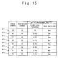
- FIG. 15 is a table showing one example of active measurement results in the second exemplary embodiment of the present invention.
- FIG. 16 is a diagram showing one example of the flow quality/routed link table in the second exemplary embodiment of the present invention.
- FIG. 17 is a diagram showing one example of the flow quality/routed link table after removal of non-degradation links in the second exemplary embodiment of the present invention.
- FIG. 1 is a block diagram showing the configuration of the communication network system according to a first exemplary embodiment of the present invention.
- a network N 1 is a management target network targeted for estimation of a network quality degradation portion.
- Routers (or switches) R 1 to R 10 are arranged, and terminals T 1 to T 5 and a quality degradation portion estimating server S 1 and passive measuring units P 1 and P 2 are connected.
- the network N 1 is connected to other networks N 2 to N 5 , and terminals T 10 , T 20 , T 30 , T 40 and T 50 are connected to the other networks N 2 to N 5 .
- Each of the passive measuring units P 1 and P 2 has a first passive measuring function for passively measuring E2E flow quality data between a transmitting terminal and a receiving terminal, and a second passive measuring function for measuring upstream flow quality data between the transmitting terminal and the passive measuring unit.
- Each of the passive measuring units P 1 and P 2 periodically notifies E2E flow quality data, which is measured by using the first passive measuring function, to the quality degradation portion estimating server S 1 .
- the notified E2E flow quality data includes data (such as an address of the transmitting terminal, an address of the receiving terminal, and a data of communication quality).
- the data of the communication quality is a data of communication quality such as the packet loss rate, the burst property of a packet loss, a reception rate, and delay jitter.
- a specific example of the second passive measuring function of each of the passive measuring units P 1 and P 2 is a method of determining the communication quality, such as the number of packet losses and variation of packet delays, on a route between the transmitting terminal and the passive measurement point and the variation of packet delay, from known data of a packet sequence in the communication flow transmitted from the transmitting terminal (a sequence number, the number of transmission packets per unit time, and a variation of time intervals between the transmission packets) and data of the packet sequence in the communication flow from the transmitting terminal which is measured at the passive measurement point (the sequence number, the number of pass packets per unit time, and a variation of passage packets) (this is referred to as an upstream quality estimating method).
- the notified upstream flow quality data includes a data (such as an identifier of a link to which the passive measuring unit is connected, an address of the transmitting terminal, an address of the receiving terminal, and a data of communication quality).
- the data of communication quality is such as a packet loss rate, a burst property of the packet loss, a reception rate, and a delay jitter.
- the quality degradation portion estimating server S 1 collects the E2E flow quality data and the upstream flow quality data from each of the packet measuring units P 1 and P 2 in the network N 1 and also collects route data from the respective routers R 1 to R 10 , and detects the generation of the degradation of communication quality in the network N 1 and then estimates the quality degradation portion.
- the quality degradation portion estimating server S 1 contains an E2E flow quality data collecting section 101 , upstream flow quality data collecting section 102 , a flow quality data determining section 103 , a route data collecting section 104 , a flow quality/routed link table managing section 105 , a table storage section 106 , a quality degradation portion estimating section 107 and a display section 108 .
- the E2E flow quality data collecting section 101 receives the E2E flow quality data periodically notified from the passive measuring units P 1 and P 2 .
- the E2E flow quality data includes the data (such as the address of the transmitting terminal, the address of the receiving terminal and the data of communication quality).
- the upstream flow quality data collecting section 102 receives the upstream flow quality data periodically notified from the passive measuring units P 1 and P 2 .
- the upstream flow quality data includes the data (such as the identifier of the link to which the passive measuring unit is connected, the address of the transmitting terminal, the address of the receiving terminal, and the data of communication quality).
- the flow quality data determining section 103 receives the E2E flow quality data from the E2E flow quality data collecting section 101 and receives the upstream flow quality data from the upstream flow quality data collecting section 102 .
- the flow quality data determining section 103 extracts the E2E flow quality data that the degradation of flow quality is not indicated in the upstream flow quality data related to the same transmitting and receiving terminals among the E2E flow quality data, and then notifies it to the flow quality/routed link table managing section 105 , together with an identifier of the link to which the passive measuring unit is connected.
- the flow quality data determining section 103 executes the following process on all the E2E flow quality data in which the transmitting terminal exists in the other networks N 2 to N 5 and the receiving terminal exists in
- the upstream flow quality data to the same transmitting and receiving terminals as the transmitting and receiving terminals of the E2E flow quality data is searched, and if it does not exist, the process about the E2E flow quality data is ended, and if it exists, a step 2 is executed.
- Whether or not the communication quality of the existing upstream flow quality data is good is determined by comparing with a predetermined condition of a flow of good quality, and if it is not good (if the quality is deteriorated), the process about the E2E flow quality data is ended, and if it is good, a step 3 is executed.
- the flow quality data of the identifier of the link connected to the passive measuring unit and included in the upstream flow quality data of good quality, the address of the receiving terminal, and the quality data of the E2E flow quality data is notified to the flow quality/routed link table managing section 105 .
- the route data collecting section 104 collects routing data, namely, a data of a routing from the routers (or switches) R 1 to R 10 in the network N 1 .
- the collected data are a routing tables and an ARP table when they are collected from the routers, and the collected data are a forwarding database and a configuration data of a spanning tree when they are collected from the switch. They can be collected by using SMTP (Simple Network Management Protocol) and the like. If there is a data of routing, the route through which the communication between the transmitting and receiving terminals is carried out can be determined from the address data of the transmitting and receiving terminals. It should be noted that the data of routing can be given by a network manager without any collection from the routers (or switches) R 1 to R 10 .
- the flow quality/routed link table managing section 105 manages the communication quality and a data of routed links in the flow carried out currently by using a table based on the flow quality data obtained from the flow quality data determining section 103 and a data of routing obtained from the route data collecting section 104 .
- the table used in this management is referred to as a flow quality/routed link table.
- the flow quality/routed link table holds an identifier of the link to which the passive measuring unit is connected, the address of the receiving terminal, a link set through which the flow is currently routed, and a quality flag indicating the current communication quality of the flow, for each flow in which the communication is currently carried out.
- the link is a directional link between the routers (or switches) or between the route (or switch) and the terminal.
- the directional link Li i is an integer shown in FIG. 3 .
- the quality flag takes any of three states of 1, 0 and indefinite (hereinafter, to be represented as N/A). For example, a quality index is determined from the packet loss rate, the burst property of the packet loss, the reception rate, the delay jitter and the like, which are included in the communication quality data of the flow quality data. If this determined quality index is equal to or higher than a predetermined bad state threshold, the quality flag is set to “1” to indicate the degradation. Also, if the determined quality index is equal to or less than a predetermined good state threshold, the quality flag is set to “0” to indicate that it is not deteriorated. If the determined quality index is not the above cases, the quality flag is set to N/A.
- the quality index may be simply determined from one (for example, the packet loss rate) of the communication quality data. Or, in case of a flow of VoIP, an R value is determined based on E-Model of G.107 of an ITU-T recommendation from the packet loss rate and the delay jitter and the like, and it may be used as the quality index.
- the table storage section 106 stores the flow quality/routed link table.
- the quality degradation portion estimating section 107 periodically reads the flow quality/routed link table from the table storage section 106 and estimates a quality degradation portion based on the data of the routed links of the flow in which the quality flag is set to “1” to outputs to the display section 108 .
- the estimating method of the quality degradation portion it is possible to employ the method described in the related art 3. However, in order to make an estimation precision higher, it is preferable to use the following minimum link number estimating method and maximum probability estimating method.
- the minimum link number estimating method is a method of estimating, as the quality degradation portion, network components included in a combination in which the number of components is minimum, among all of combinations of the network components which may generate the quality degradation in the flow.
- the reason why the combination in which the number of components is minimum is selected is in that, when probabilities that the qualities of the respective network components are deteriorated are assumed to be equal, the combination in which the number of components is minimum has the highest probability.
- the maximum probability estimating method is a method of estimating, as the quality degradation portion, network components included in a combination in which the generation probability of the quality degradation is the highest among all of combinations of the network components which may generate the quality degradation in the flow.
- the quality degradation probability of each network component is set in advance. When the quality degradation probabilities of the respective network components are assumed to be equal, it is equivalent to that of the minimum link number estimating method.
- the display section 108 is provided with a display to display the quality degradation portion estimated by the quality degradation portion estimating section 107 to the network manager.
- the display for specifying the quality degradation portion may be shown by using a text such as the address of the link, or may be graphically shown on a network diagram.
- flows F 1 to F 5 shown in FIG. 4 present on the communication network system shown in FIG. 1 All of the flows F 1 to F 5 are user flows in which the terminals T 10 , T 20 , T 30 , T 40 and T 50 connected to the networks other than the management target network N 1 are used as the transmitting terminals, and the terminals T 1 , T 2 , T 3 , 24 and T 5 connected to the management target network N 1 are used as the receiving terminals.
- the passive measuring unit P 1 measures the E2E flow quality data and the upstream flow quality data for the flows F 1 , P 2 and F 5 to notify to the E2E flow quality data collecting section 101 and the upstream flow quality data collecting section 102 in the quality degradation portion estimating server S 1 .
- the passive measuring unit P 2 measures the E2E flow quality data and the upstream flow quality data for the flows F 3 and F 4 to notify to the E2E flow quality data collecting section 101 and the upstream flow quality data collecting section 102 in the quality degradation portion estimating server S 1 .
- the E2E flow quality data collecting section 101 in the quality degradation portion estimating server S 1 notifies the E2E flow quality data received from the passive measuring units P 1 and P 2 to the flow quality data determining section 103 .
- the upstream flow quality data collecting section 102 notifies the upstream flow quality data received from the passive measuring units P 1 and P 2 to the flow quality data determining section 103 .
- FIG. 5 shows one example of the E2E flow quality data notified to the flow quality data determining section 103 from the E2E flow quality data collecting section 101 .
- FIG. 6 shows one example of the upstream flow quality data notified to the flow quality data determining section 103 from the upstream flow quality data collecting section 102 .
- the packet loss rate and the delay variation are used as the communication quality.
- the flow quality data determining section 103 executes the above step 1 to step 3 on all of the E2E flow quality data of the flows in which the transmitting terminal exists in the other networks N 2 to N 5 and the receiving terminal exists in the network N 1 .
- the flow quality data determining section 103 extracts the E2E flow quality data that does not show the degradation of flow quality in the upstream flow quality data related to the same transmitting and receiving terminals, among the E2E flow quality data and notifies it to the flow quality/routed link table managing section 105 together with the identifier of the link to which the passive measuring unit is connected.
- the flow F 1 in the first row of FIG. 6 is removed from a notice to the flow quality/routed link table managing section 105 , because the upstream flow quality in the first row of FIG. 5 related to the same transmitting and receiving terminals is not good.
- the flows F 2 to F 5 in the remaining second to fifth rows of FIG. 6 are targeted for the notice to the flow quality/routed link table managing section 105 , because the upstream flow quality in the second to fifth rows of FIG. 5 related to the same transmitting and receiving terminals is good.
- the data shown in FIG. 7 is notified to the flow quality/routed link table managing section 105 .
- the flow quality/routed link table managing section 105 maintains the flow quality/routed link table provided with the identifier of the link to which the passive measuring unit is connected, the address of the receiving terminal, the link set through which flows are currently routed, and the quality flag indicating the current communication quality of each flow, for the flows in which the communications are currently carried out, based on the flow quality data obtained from the flow quality data determining section 103 and the data of routing from the route data collecting section 104 . For example, when the packet loss rate is defined as the quality degradation index, the bad state threshold is 3%, and the good state threshold is 1%, if the flow quality data shown in FIG. 7 is obtained from the flow quality data determining section 103 , this results in the flow quality/routed link table shown in FIG. 8 . It should be noted that in FIG. 8 , the links in which “1” is set in the column of the routed link are the routed links of the flows.
- the quality degradation portion estimating section 107 estimates the quality degradation portion based on the flow quality/routed link table shown in FIG. 8 an displays its result on the display section 108 .
- FIG. 9 shows an operation flowchart of the quality degradation portion estimating section 107 when the minimum link number estimating method is used.
- the quality degradation portion estimating section 107 reads the flow quality/routed link table from the table storage section 106 (Step 201 ). Subsequently, whether or not the quality degradation flow in which the quality flag is set to “1” exists in the flow quality/routed link table is determined (Step 202 ). If the quality degradation flow does not exist, the process for this time is ended.
- Step 203 If one or more quality degradation flows exist, a quality non-degradation link is removed (Step 203 ). After that, the minimum link number estimating method is performed to estimate the quality degradation portion (Step 204 ), and its result is displayed on the display section 108 (Step 205 ).
- the removal of the quality non-deteriorated link executed at the step 203 is to remove the same links as the routed links of the flow in which “0” is set to the quality flag, from the routed links for the flow in which “1” is set to the quality flag.
- the flows F 4 and F 5 are the good flows (the quality flag set to 0), and links L 10 , L 30 , L 70 and L 80 through which the flows F 4 and F 5 routed are considered not to show the quality degradation.
- they are removed from the routed links of the flows F 2 and F 3 in which the quality flags are set to “1”.
- the flow quality/routed link table is as shown in FIG. 10 .
- a set of flows for which “1” has been set is referred to as a flow set belonging to the link sequence.
- the flow set belonging to the sequence of routed links L 20 is ⁇ F 2 , F 3 ⁇ .
- a summation set of the flow sets belonging to a plurality of sequences of routed links is similarly referred to as the flow set belonging to the set of those link sequence.
- the flow set belonging to sets ⁇ L 50 , L 60 ⁇ of the link sequence is ⁇ F 2 , F 3 ⁇ .
- the minimum link number estimating method executes the following step 1 to step 3.
- the set composed of the minimum number of the elements is selected from the sets of the routed link sequence in which the flow set belonging to the sets of the routed link sequence is same as the flow extracted at the step 1.
- the routed link set (the plurality of routed link sets are allowable) obtained at the step 2 is outputted as the result.
- the above description is about the operation of the quality degradation portion estimating section 107 when the minimum link number estimating method is used.
- the operation of the quality degradation portion estimating section 107 when the maximum probability estimating method is used is as shown in FIG. 11 .
- the step 211 of the maximum probability estimation is executed instead of the step 204 of the minimum link number estimating method.
- a probability resulting in its cause is stored in a quality degradation cause probability table for each of the links in the management target network N 1 .
- This quality degradation cause probability table is stored in the table storage section 106 .
- the maximum probability estimating method executes the following step 1 to step 3.
- a set in which the estimation generation probability is maximum is selected from the sets of routed link sequences in which the flow set belonging to the sets of routed link sequences is the same as the flow extracted at the step 1.
- the estimation generation probability is such that the probabilities resulting in the quality degradation cause of the respective links, which are stored in the quality degradation cause probability table, are multiplied with each other.
- the routed link set (the plurality of routed link sets are allowable) obtained at the step 2 is outputted as the result.
- the generation of the degradation of communication quality in the management target network N 1 can be detected by using the E2E flow quality data between the transmitting and receiving terminals, which are measured by the passive measuring units P 1 and P 2 dispersedly arranged in the management target network N 1 .
- the upstream flow quality data between the transmitting terminal and the passive measuring units P 1 and P 2 is measured, simultaneously with the measurement of the E2E flow quality data between the transmitting terminal and the receiving terminal, and a flow related to the E2E flow quality data that does not show the degradation of flow quality in the upstream flow quality data related to the same transmitting and receiving terminals is detected as the quality degradation flow in the management target network from among the E2E flow quality data showing the degradation of flow quality.
- a quality degradation portion in the management target network N 1 can be estimated by using the E2E flow quality data between the transmitting and receiving terminals, which are measured by the passive measuring units P 1 and P 2 dispersedly arranged in the management target network N 1 .
- the upstream flow quality data between the transmitting terminal and the passive measuring units P 1 and P 2 is measured, simultaneously with the measurement of the E2E flow quality data between the transmitting terminal and the receiving terminal, and the flow related to the E2E flow quality data that does not show the degradation of flow quality in the upstream flow quality data related to the same transmitting and receiving terminals is detected as the quality degradation flow in the management target network from among the E2E flow quality data showing the degradation of flow quality, and the quality degradation portion in the management target network N 1 is estimated based on the quality degradation flow in the management target network and the route data of the management target network N 1 .
- a flow in which the transmitting terminal exists in another network and the receiving terminal exists in the management target network N 1 is used among the flows flowing through the management target network N 1 .
- any one of (1) a flow when both of the transmitting terminal and the receiving terminal exist in the management target network N 1 , and (2) a flow in which the transmitting terminal exists in the management target network N 1 and the receiving terminal exists in another network, or both of them may be used to estimate the quality degradation portion.
- the E2E flow quality data itself is used, and when the flow in case of (2) is used, the upstream flow quality data is used. That is, the flow quality data determining section 103 in the quality degradation portion estimating server S 1 notifies the E2E flow quality data related to the flow as the flow quality data to the flow quality/routed link table managing section 105 , when both of the transmitting and receiving terminals exist in the management target network N 1 , and notifies the upstream flow quality data between the transmitting and receiving terminals as the flow quality data to the flow quality/routed link table managing section 105 when the transmitting terminal exists in the management target network N 1 and the receiving terminal exists in the other network.
- the flow quality/routed link table managing section 105 deals with them similarly to the flow when the transmitting terminal exists in different network.
- the set of “Probe Position and Transmission Destination Address” in FIG. 7 is a set of “Transmission Source Address and Transmission Destination Address”, in the flow when both of the transmitting and receiving terminals exist in the management target network N 1 , and is a set of “Transmission Source Address and Probe Position”, in the flow when the receiving terminal exists in the other network.
- the quality non-degradation link is removed before the minimum link number estimating method or maximum probability estimating method is executed.
- the process for removing this quality non-degradation link may be omitted.
- the communication network system differs from the first exemplary embodiment shown in FIG. 1 , in that active measuring units A 5 and A 6 are arranged at the same points as the passive measurement points of the passive measuring units P 1 and P 2 dispersedly arranged in the management target network N 1 , that active measuring units A 1 to A 4 are arranged at the boundary points with different networks, and that the quality degradation portion estimating server S 1 collects the E2E flow quality data and the upstream flow quality data from the passive measuring units P 1 and P 2 and further collects the actively-measured quality data from the active measuring units A 1 to A 6 .
- Each of the active measuring units A 1 to A 5 has a function of sending a test packet between the unit and a different active measuring unit, consequently measuring the communication quality between them, and then transmitting the measurement result to the quality degradation portion estimating server S 1 .
- the measurement result includes the address of a transmitting active measuring unit, the address of a receiving active measuring unit, and the data of communication quality.
- the communication quality is a data of communication quality such as the packet loss rate, the burst property of the packet loss, the reception rate, the delay jitter and the like.
- the quality degradation portion estimating server S 1 in this exemplary embodiment differs from the quality degradation portion estimating server S 1 in the first exemplary embodiment shown in FIG. 2 in that an active measurement quality data collecting section 109 is newly added and the function of the flow quality/routed link table managing section 105 is enhanced.
- the E2E flow quality data collecting section 101 , the upstream flaw quality data collecting section 102 , the flow quality data determining section 103 , the route data collecting section 104 , the table storage section 106 , the quality degradation portion estimating section 107 and the display section 108 are similar to the first exemplary embodiment.
- the active measurement quality data collecting section 109 instructs the active measuring units A 1 to A 6 to carry out the active measurements and receives the measurement results, namely, the set of data (the address of the transmitting active measuring unit, the address of the receiving active measuring unit, and the data of communication quality), and then notifies to the flow quality/routed link table managing section 105 .
- the flow quality/routed link table managing section 105 adds the data of the address of the active measuring unit on the transmitting side, the address of the active measuring unit on the receiving side, a link set through which the flow is routed, and a quality flag indicating communication quality of the flow, to the flow quality/routed link table, in the flow related to the active measurement, based on the active measurement quality data from the active measurement quality data collecting section 109 and the routing data from the route data collecting section 104 , in addition to the operation of the flow quality/routed link table managing section 105 in the first exemplary embodiment.
- the definition of the link and a setting method of the quality flag are similar to the first exemplary embodiment.
- the active measurement quality data collecting section 109 in the quality degradation portion estimating server S 1 instructs the active measurement between the active measuring unit A 4 and the active measuring unit A 5 , between the active measuring unit A 3 and the active measuring unit A 5 , between the active measuring unit A 2 and the active measuring unit A 6 and between the active measuring unit A 1 and the active measuring unit A 6 , as shown by arrows in FIG. 14 . Consequently, the quality data between the passive measuring units P 1 and P 2 and the boundary points with the different networks are passively measured.
- FIG. 15 shows one example of the active measurement result at this time.
- the active measurement quality data collecting section 109 in the quality degradation portion estimating server S 1 notifies it to the flow quality/routed link table managing section 105 .
- the flow quality/routed link table managing section 105 determines that a flow AF 1 of the first row in FIG. 15 is a flow of bad quality and flows AF 2 to AF 8 other than it are flows of good quality, when a flow in which the delay variation is 60 ms or less and the packet loss rate is 1% or less is assumed to be the condition of the flow having good communication quality.
- the flow quality/routed link table managing section 105 adds data of the address of the active measuring unit on the transmitting side, the address of the active measuring unit on the receiving side, the link set through which the flow is routed, and the quality flag indicating the communication quality of the flow, to the flow quality/routed link table.
- the E2E flow quality data shown in FIG. 5 and the upstream flow quality data shown in FIG. 6 are measured by the passive measuring units P 1 and P 2 and sent to the quality degradation portion estimating server S 1 , and when the flow quality/routed link table shown in FIG. 8 is generated based on them, the flow quality/routed link table to which the active measurement result is added becomes a state shown in FIG. 16 .
- the flows AF 2 , AF 4 , AF 6 and AF 8 are omitted in FIG. 16 .
- the quality degradation portion estimating section 107 reads the flow quality/routed link table shown in FIG. 16 from the table storage section 106 and removes the non-degradation link to generate the flow quality/routed link table shown in FIG. 17 , and then estimates a link set ⁇ L 20 , L 300 ⁇ as the quality degradation portion by using the minimum link number estimating method. That is, in this case, the quality degradation in the link L 300 that is missed in the first exemplary embodiment is detected.
- the estimation of the quality degradation portion requires both of the data of the presence or absence of the quality degradation in the flow and the route through which it passes.
- the passive measuring units P 1 and P 2 there is a case that the presence or absence of the quality degradation on the route from the network boundary point to the packet measurement point is not known or there is a case that the route itself is not known. Also, there is a case that the presence or absence of the quality degradation on the route from the packet measurement point to the network boundary point is not also known.
- the passive measurement point and the network boundary point it is possible to carry out active measurement between the passive measurement point and the network boundary point and consequently clarify the presence or absence of the quality degradation between the passive measurement point and the network boundary point, and also use the fact that the route of the flow of the active measurement is clear and consequently estimate the quality degradation portion on the route between the network boundary point and the passive measurement point.
- the quality measurement result based on the passive measurement point as compared with a case of carrying out the active measurement only between the passive measurement point and the network boundary point, the improvement of the estimation precision of the same route and the estimation of the quality degradation portion in a route other than the same route are attained at the same time.
- the function of the quality degradation portion estimating server S 1 can be naturally attained in hardware. Moreover, this may be attained by a computer and a program. The program is recorded on a computer-readable recording medium such as a magnetic disc and a semiconductor memory, and this is read by the computer when the computer is started. Thus, since the operation of the computer is controlled, the computer functions as the quality degradation portion estimating server S 1 in the above-mentioned respective exemplary embodiments.
- the generation of the degradation of communication quality in the management target network can be detected by using the E2E flow quality data when the transmitting terminal exists in a different network, among the E2E flow quality data between the transmitting and receiving terminals that are measured by the passive measuring method, hereby estimating the quality degradation portion.
- the upstream flow quality data of the zone between the transmitting terminal and the passive measuring unit is measured, simultaneously with the measurement of the E2E flow quality data on the route between the transmitting terminal and the receiving terminal, and the flow related to the E2E flow quality data that does not show the degradation of flow quality, for the upstream flow quality data related to the same transmitting and receiving terminals among the E2E flow quality data showing the degradation of flow quality is detected as the quality degradation flow in the management target network.
- the degradation of communication quality in the management target network can be detected based on the quality data when the passive measurement is carried out to the flow, thereby estimating the quality degradation portion.
- a collecting section configured to collect E2E flow quality data on a route between a transmitting terminal connected to a different network and a receiving terminal connected to a management target network, and upstream flow quality data on the route between the transmitting terminal and the passive measuring unit, which are measured by a passive measuring unit connected to the management target network, and a degradation flow detecting unit configured to detect a flow related to the E2E flow quality data that does not show a degradation of flow quality, for the upstream flow quality data related to the same transmitting and receiving terminals as a quality degradation flow in the management target network, from among the E2E flow quality data that show the degradation of flow quality, based on the collected E2E flow quality data and upstream flow quality data.
- a collecting section configured to collect E2E flow quality data on a route between a transmitting terminal connected to a different network and a receiving terminal connected to a management target network, and upstream flow quality data on the route between the transmitting terminal and a passive measuring unit, which are measured by the passive measuring unit connected to the management target network, and a flow quality data between a boundary point with the different network and the passive measurement point arranged with the passive measuring unit, which are measured by active measuring units arranged at the passive measurement point and the boundary point, and a degradation flow detecting unit configured to detect a flow related to the E2E flow quality data that does not show degradation of flow quality, for the upstream flow quality data related to the same transmitting and receiving terminals from among the E2E flow quality data that show the degradation of flow quality and a flow that show the degradation of flow quality, of the flow quality data on the route between the boundary point and the passive measurement point, as a quality degradation flow in the management target network, based on the collected E2E
- an estimating section configured to estimate a quality degradation portion in the management target network, based on the quality degradation flow in the management target network and a route data of the management target network.
- the estimating section estimates, as the quality degradation portion, a network component included in a combination in which the number of components is minimum, among all the combinations of the network components that may generate the quality degradation in the quality degradation flow in the management target network.
- the estimating section refers to quality degradation probabilities of the network components and estimates as the quality degradation portion, the network component included in a combination in which the generation probability of the quality degradation is the highest, among all the combinations of the network components that may generate the quality degradation in the quality degradation flow in the management target network.
Abstract
Description
Claims (16)
Applications Claiming Priority (4)
| Application Number | Priority Date | Filing Date | Title |
|---|---|---|---|
| JP2006-225181 | 2006-08-22 | ||
| JP2006225181 | 2006-08-22 | ||
| JP2006225181 | 2006-08-22 | ||
| PCT/JP2007/065519 WO2008023570A1 (en) | 2006-08-22 | 2007-08-08 | Method for estimating quality-degraded portion on a network in a communication network system |
Publications (2)
| Publication Number | Publication Date |
|---|---|
| US20100177646A1 US20100177646A1 (en) | 2010-07-15 |
| US8036121B2 true US8036121B2 (en) | 2011-10-11 |
Family
ID=39106657
Family Applications (1)
| Application Number | Title | Priority Date | Filing Date |
|---|---|---|---|
| US12/438,243 Expired - Fee Related US8036121B2 (en) | 2006-08-22 | 2007-08-08 | Method of estimating quality degradation on network in communication network system |
Country Status (4)
| Country | Link |
|---|---|
| US (1) | US8036121B2 (en) |
| JP (1) | JP5120784B2 (en) |
| CN (1) | CN101507205A (en) |
| WO (1) | WO2008023570A1 (en) |
Cited By (4)
| Publication number | Priority date | Publication date | Assignee | Title |
|---|---|---|---|---|
| US20100254397A1 (en) * | 2009-04-07 | 2010-10-07 | Fujitsu Limited | Communication route presumption technique |
| JP2017034403A (en) * | 2015-07-30 | 2017-02-09 | 日本電信電話株式会社 | Device, program and method for estimating service influence cause |
| US9736045B2 (en) | 2011-09-16 | 2017-08-15 | Qualcomm Incorporated | Systems and methods for network quality estimation, connectivity detection, and load management |
| US20230098774A1 (en) * | 2020-03-27 | 2023-03-30 | Nec Corporation | Communication device, communication controlling method, and non-transitory computer-readable media |
Families Citing this family (15)
| Publication number | Priority date | Publication date | Assignee | Title |
|---|---|---|---|---|
| WO2006137373A1 (en) * | 2005-06-24 | 2006-12-28 | Nec Corporation | Quality degradation portion deducing system and quality degradation portion deducing method |
| JP4863090B2 (en) * | 2007-08-23 | 2012-01-25 | 日本電気株式会社 | Communication network quality degradation location estimation apparatus, method, program, and communication network system |
| JP5052552B2 (en) * | 2009-03-18 | 2012-10-17 | 日本電信電話株式会社 | FAILURE LOCATION DETECTING METHOD, FAILURE LOCATION DETECTION DEVICE, FAILURE LOCATION DETECTION PROGRAM, AND RECORDING MEDIUM FOR FAILURE LOCATION DETECTION PROGRAM |
| US9112894B2 (en) * | 2009-05-08 | 2015-08-18 | Universiti Sains Malaysia | Real time distributed network monitoring and security monitoring platform (RTD-NMS) |
| US8274902B2 (en) * | 2009-08-12 | 2012-09-25 | Alcatel Lucent | Estimation method for loss rates in a packetized network |
| JP5494110B2 (en) * | 2010-03-29 | 2014-05-14 | 富士通株式会社 | Network communication path estimation method, communication path estimation program, and monitoring apparatus |
| JP5655651B2 (en) * | 2010-06-09 | 2015-01-21 | 富士通株式会社 | Abnormality detection apparatus, communication abnormality detection system, communication abnormality detection method, and program |
| JP2012129868A (en) * | 2010-12-16 | 2012-07-05 | Nec Corp | Communication system |
| JP5958354B2 (en) * | 2013-01-16 | 2016-07-27 | 富士通株式会社 | Communication monitoring apparatus, occurrence prediction method, and occurrence prediction program |
| JP5987701B2 (en) * | 2013-01-16 | 2016-09-07 | 富士通株式会社 | Communication monitoring apparatus, prediction method, and prediction program |
| US8842578B1 (en) * | 2013-05-09 | 2014-09-23 | Yehuda Zisapel | End-to-end (E2E) application packet flow visibility |
| JP6310405B2 (en) * | 2015-02-06 | 2018-04-11 | 日本電信電話株式会社 | Service impact cause estimation apparatus, service impact cause estimation program, and service impact cause estimation method |
| TWI674777B (en) * | 2018-11-09 | 2019-10-11 | 財團法人資訊工業策進會 | Abnormal flow detection device and abnormal flow detection method thereof |
| CN110191027B (en) * | 2019-06-19 | 2022-08-16 | 上海电气泰雷兹交通自动化系统有限公司 | Communication error diagnosis method between CCU and MCU |
| CN113905396B (en) * | 2021-09-10 | 2024-03-12 | 河南信安通信技术股份有限公司 | Mobile phone signal measurement equipment and method for LTE active and passive depth fusion |
Citations (12)
| Publication number | Priority date | Publication date | Assignee | Title |
|---|---|---|---|---|
| US5815668A (en) | 1995-03-17 | 1998-09-29 | Nec Corporation | Slave inter-lan connection device, an inter-lan connection system and a hot standby method of said inter-lan connection system |
| JP2000224172A (en) | 1999-02-04 | 2000-08-11 | Fujitsu Ltd | Method and instrument for measuring network communication performance, and computer-readable recording medium stored with network communication performance measuring program |
| JP2002064493A (en) | 2000-08-18 | 2002-02-28 | Nippon Telegr & Teleph Corp <Ntt> | Method and system for managing communication path |
| JP2002064545A (en) | 2000-08-15 | 2002-02-28 | Nippon Telegr & Teleph Corp <Ntt> | Network quality management method and device |
| JP2002271267A (en) | 2001-03-07 | 2002-09-20 | Nec Corp | Network node device, and network system using the same, and method of detecting its hindrance location |
| JP2002271392A (en) | 2001-03-06 | 2002-09-20 | Nippon Telegr & Teleph Corp <Ntt> | Method of controlling voice quality every call in ip net |
| JP2003258903A (en) | 2002-03-04 | 2003-09-12 | Hitachi Ltd | Communication line monitor system |
| JP2005210515A (en) | 2004-01-23 | 2005-08-04 | Nippon Telegr & Teleph Corp <Ntt> | Method and device for single-point observation type measurement of network quality |
| JP2006033715A (en) | 2004-07-21 | 2006-02-02 | Nippon Telegr & Teleph Corp <Ntt> | Network e2e performance evaluation system, method, and program |
| JP2006080584A (en) | 2004-09-07 | 2006-03-23 | Nippon Telegr & Teleph Corp <Ntt> | Method for separating quality deteriorated part of packet switch network and apparatus therefor, and program and recording medium therefor |
| US20070211645A1 (en) * | 2006-03-07 | 2007-09-13 | Kddi R&D Laboratories, Inc. | Method and management apparatus for classifying congestion paths based on packet delay |
| US7606896B2 (en) | 2005-02-24 | 2009-10-20 | Nec Corporation | Device, method, and program for estimating quality-deteriorated area of network |
-
2007
- 2007-08-08 CN CNA2007800313381A patent/CN101507205A/en active Pending
- 2007-08-08 JP JP2008530849A patent/JP5120784B2/en not_active Expired - Fee Related
- 2007-08-08 WO PCT/JP2007/065519 patent/WO2008023570A1/en active Application Filing
- 2007-08-08 US US12/438,243 patent/US8036121B2/en not_active Expired - Fee Related
Patent Citations (12)
| Publication number | Priority date | Publication date | Assignee | Title |
|---|---|---|---|---|
| US5815668A (en) | 1995-03-17 | 1998-09-29 | Nec Corporation | Slave inter-lan connection device, an inter-lan connection system and a hot standby method of said inter-lan connection system |
| JP2000224172A (en) | 1999-02-04 | 2000-08-11 | Fujitsu Ltd | Method and instrument for measuring network communication performance, and computer-readable recording medium stored with network communication performance measuring program |
| JP2002064545A (en) | 2000-08-15 | 2002-02-28 | Nippon Telegr & Teleph Corp <Ntt> | Network quality management method and device |
| JP2002064493A (en) | 2000-08-18 | 2002-02-28 | Nippon Telegr & Teleph Corp <Ntt> | Method and system for managing communication path |
| JP2002271392A (en) | 2001-03-06 | 2002-09-20 | Nippon Telegr & Teleph Corp <Ntt> | Method of controlling voice quality every call in ip net |
| JP2002271267A (en) | 2001-03-07 | 2002-09-20 | Nec Corp | Network node device, and network system using the same, and method of detecting its hindrance location |
| JP2003258903A (en) | 2002-03-04 | 2003-09-12 | Hitachi Ltd | Communication line monitor system |
| JP2005210515A (en) | 2004-01-23 | 2005-08-04 | Nippon Telegr & Teleph Corp <Ntt> | Method and device for single-point observation type measurement of network quality |
| JP2006033715A (en) | 2004-07-21 | 2006-02-02 | Nippon Telegr & Teleph Corp <Ntt> | Network e2e performance evaluation system, method, and program |
| JP2006080584A (en) | 2004-09-07 | 2006-03-23 | Nippon Telegr & Teleph Corp <Ntt> | Method for separating quality deteriorated part of packet switch network and apparatus therefor, and program and recording medium therefor |
| US7606896B2 (en) | 2005-02-24 | 2009-10-20 | Nec Corporation | Device, method, and program for estimating quality-deteriorated area of network |
| US20070211645A1 (en) * | 2006-03-07 | 2007-09-13 | Kddi R&D Laboratories, Inc. | Method and management apparatus for classifying congestion paths based on packet delay |
Non-Patent Citations (8)
| Title |
|---|
| Empirical Study on Locating Congested Segments over the Internet Based on Multiple End-to-End Path Measurements by Tachibana et al. 2005. * |
| Hajime Sugimura et al.-Packet Monitoring and Testing Methods for VolP Networks-2001-p. 1. |
| Infering link characteristics from end-to-end path meadurements by Tsuru et al. 2001. * |
| Japanese Office Action dated Dec. 2, 2010 in corresponding Japanese Application No. 2007-522279 with English translation of enclosed wavy lined portion. |
| Masayoshi Kobayashi et al., "Estimating points of QoS degradation in the network from the aggregation of per-flow quality information" (IEICE Technical Report, vol. 104, No. 707, IEICE, Mar. 11, 2005. |
| Masayoshi Kobayashi et al., "Flow Hinshitsu Kara no Network Hinshitsu Rekka Kasho Suitei no Mobunkatsu ni yoru Daikiboka Shuho no Teian to Hyoka", IEICE Technical Report CS2005-35, Sep. 8, 2005, vol. 105, No. 280, "2.1. Jurai Hoshiki no Gairyaku", "3. Mobunkatsu ni yoru Daikibomo eno Tekiyo Hoshiki". |
| Masayoshi Kobayashi et al.-Estimating points of QoS degradation in the network from the aggregation of per-flow quality information-Systems Platforms Research Laboratories, NEC Corporation-pp. 1-6. |
| United States Office Action-U.S. Appl. No. 11/993,155-Oct. 28, 2010. |
Cited By (6)
| Publication number | Priority date | Publication date | Assignee | Title |
|---|---|---|---|---|
| US20100254397A1 (en) * | 2009-04-07 | 2010-10-07 | Fujitsu Limited | Communication route presumption technique |
| US8274898B2 (en) * | 2009-04-07 | 2012-09-25 | Fujitsu Limited | Communication route presumption technique |
| US9736045B2 (en) | 2011-09-16 | 2017-08-15 | Qualcomm Incorporated | Systems and methods for network quality estimation, connectivity detection, and load management |
| JP2017034403A (en) * | 2015-07-30 | 2017-02-09 | 日本電信電話株式会社 | Device, program and method for estimating service influence cause |
| US20230098774A1 (en) * | 2020-03-27 | 2023-03-30 | Nec Corporation | Communication device, communication controlling method, and non-transitory computer-readable media |
| US11848700B2 (en) * | 2020-03-27 | 2023-12-19 | Nec Corporation | Communication device, communication controlling method, and non-transitory computer-readable media |
Also Published As
| Publication number | Publication date |
|---|---|
| JPWO2008023570A1 (en) | 2010-01-07 |
| JP5120784B2 (en) | 2013-01-16 |
| WO2008023570A1 (en) | 2008-02-28 |
| CN101507205A (en) | 2009-08-12 |
| US20100177646A1 (en) | 2010-07-15 |
Similar Documents
| Publication | Publication Date | Title |
|---|---|---|
| US8036121B2 (en) | Method of estimating quality degradation on network in communication network system | |
| JP4244940B2 (en) | Network quality degradation location estimation apparatus, quality degradation location estimation method, and quality degradation location estimation program | |
| EP1861963B1 (en) | System and methods for identifying network path performance | |
| EP2837136B1 (en) | Network availability analytics | |
| JP5051252B2 (en) | Network failure detection system | |
| EP2081321A2 (en) | Sampling apparatus distinguishing a failure in a network even by using a single sampling and a method therefor | |
| US20070064611A1 (en) | Method for monitoring packet loss ratio | |
| US8477772B2 (en) | System and method for determination of routing information in a network | |
| US8165019B2 (en) | Indirect measurement methodology to infer routing changes using statistics of flow arrival processes | |
| EP3089409A1 (en) | Method and system for restoring qos deteriorations in mpls networks | |
| KR101467137B1 (en) | In-service throughput testing in distributed router/switch architectures | |
| US20090268622A1 (en) | Route Tracing Program Configured to Detect Particular Network Element Making Type of Service Modification | |
| JP5131608B2 (en) | Quality degradation point estimation apparatus, method, and communication network system | |
| CN102325060B (en) | Link bandwidth test method and router | |
| JP4985641B2 (en) | Quality degradation location estimation apparatus, quality degradation location estimation method, and quality degradation location estimation program | |
| CN114465897A (en) | Method, device and system for monitoring data packets in service flow | |
| JP2008172655A (en) | Network system, method and program for estimating communication quality deterioration zone | |
| JP3953999B2 (en) | Congestion detection apparatus, congestion detection method and program for TCP traffic | |
| CN115550223A (en) | Service flow packet loss positioning system, method and storage medium | |
| US8639795B2 (en) | Adaptive data acquisition for a network or services management system | |
| CN112118147A (en) | MPLS-TPOAM-based LB detection method and system | |
| US8873376B2 (en) | Method of obtaining information representative of an availability, a device for obtaining information, and a corresponding computer program | |
| WO2021234900A1 (en) | Measurement device, measurement system, measurement method, and measurement program | |
| Chang et al. | Neighbor-Cooperative measurement of network path quality | |
| CN116760765A (en) | Network state detection method and device, electronic equipment and storage medium |
Legal Events
| Date | Code | Title | Description |
|---|---|---|---|
| AS | Assignment |
Owner name: NEC CORPORATION, JAPAN Free format text: ASSIGNMENT OF ASSIGNORS INTEREST;ASSIGNOR:KOBAYASHI, MASAYOSHI;REEL/FRAME:022291/0103 Effective date: 20090218 |
|
| ZAAA | Notice of allowance and fees due |
Free format text: ORIGINAL CODE: NOA |
|
| ZAAB | Notice of allowance mailed |
Free format text: ORIGINAL CODE: MN/=. |
|
| STCF | Information on status: patent grant |
Free format text: PATENTED CASE |
|
| FPAY | Fee payment |
Year of fee payment: 4 |
|
| MAFP | Maintenance fee payment |
Free format text: PAYMENT OF MAINTENANCE FEE, 8TH YEAR, LARGE ENTITY (ORIGINAL EVENT CODE: M1552); ENTITY STATUS OF PATENT OWNER: LARGE ENTITY Year of fee payment: 8 |
|
| FEPP | Fee payment procedure |
Free format text: MAINTENANCE FEE REMINDER MAILED (ORIGINAL EVENT CODE: REM.); ENTITY STATUS OF PATENT OWNER: LARGE ENTITY |
|
| LAPS | Lapse for failure to pay maintenance fees |
Free format text: PATENT EXPIRED FOR FAILURE TO PAY MAINTENANCE FEES (ORIGINAL EVENT CODE: EXP.); ENTITY STATUS OF PATENT OWNER: LARGE ENTITY |
|
| STCH | Information on status: patent discontinuation |
Free format text: PATENT EXPIRED DUE TO NONPAYMENT OF MAINTENANCE FEES UNDER 37 CFR 1.362 |
|
| FP | Lapsed due to failure to pay maintenance fee |
Effective date: 20231011 |