US8005072B2 - Synchronization of multiple base stations in a wireless communication system - Google Patents
Synchronization of multiple base stations in a wireless communication system Download PDFInfo
- Publication number
- US8005072B2 US8005072B2 US11/392,806 US39280606A US8005072B2 US 8005072 B2 US8005072 B2 US 8005072B2 US 39280606 A US39280606 A US 39280606A US 8005072 B2 US8005072 B2 US 8005072B2
- Authority
- US
- United States
- Prior art keywords
- base station
- time stamp
- counter
- time
- cmts
- Prior art date
- Legal status (The legal status is an assumption and is not a legal conclusion. Google has not performed a legal analysis and makes no representation as to the accuracy of the status listed.)
- Expired - Fee Related, expires
Links
Images


Classifications
-
- H—ELECTRICITY
- H04—ELECTRIC COMMUNICATION TECHNIQUE
- H04L—TRANSMISSION OF DIGITAL INFORMATION, e.g. TELEGRAPHIC COMMUNICATION
- H04L25/00—Baseband systems
- H04L25/02—Details ; arrangements for supplying electrical power along data transmission lines
- H04L25/03—Shaping networks in transmitter or receiver, e.g. adaptive shaping networks
- H04L25/03006—Arrangements for removing intersymbol interference
- H04L25/03343—Arrangements at the transmitter end
-
- H—ELECTRICITY
- H04—ELECTRIC COMMUNICATION TECHNIQUE
- H04J—MULTIPLEX COMMUNICATION
- H04J3/00—Time-division multiplex systems
- H04J3/02—Details
- H04J3/06—Synchronising arrangements
- H04J3/0635—Clock or time synchronisation in a network
- H04J3/0638—Clock or time synchronisation among nodes; Internode synchronisation
- H04J3/0658—Clock or time synchronisation among packet nodes
- H04J3/0661—Clock or time synchronisation among packet nodes using timestamps
- H04J3/067—Details of the timestamp structure
-
- H—ELECTRICITY
- H04—ELECTRIC COMMUNICATION TECHNIQUE
- H04L—TRANSMISSION OF DIGITAL INFORMATION, e.g. TELEGRAPHIC COMMUNICATION
- H04L12/00—Data switching networks
- H04L12/28—Data switching networks characterised by path configuration, e.g. LAN [Local Area Networks] or WAN [Wide Area Networks]
- H04L12/2801—Broadband local area networks
-
- H—ELECTRICITY
- H04—ELECTRIC COMMUNICATION TECHNIQUE
- H04B—TRANSMISSION
- H04B1/00—Details of transmission systems, not covered by a single one of groups H04B3/00 - H04B13/00; Details of transmission systems not characterised by the medium used for transmission
- H04B1/06—Receivers
- H04B1/10—Means associated with receiver for limiting or suppressing noise or interference
- H04B1/1027—Means associated with receiver for limiting or suppressing noise or interference assessing signal quality or detecting noise/interference for the received signal
- H04B1/1036—Means associated with receiver for limiting or suppressing noise or interference assessing signal quality or detecting noise/interference for the received signal with automatic suppression of narrow band noise or interference, e.g. by using tuneable notch filters
-
- H—ELECTRICITY
- H04—ELECTRIC COMMUNICATION TECHNIQUE
- H04J—MULTIPLEX COMMUNICATION
- H04J3/00—Time-division multiplex systems
- H04J3/02—Details
- H04J3/06—Synchronising arrangements
- H04J3/0635—Clock or time synchronisation in a network
- H04J3/0638—Clock or time synchronisation among nodes; Internode synchronisation
- H04J3/0658—Clock or time synchronisation among packet nodes
- H04J3/0661—Clock or time synchronisation among packet nodes using timestamps
- H04J3/0664—Clock or time synchronisation among packet nodes using timestamps unidirectional timestamps
-
- H—ELECTRICITY
- H04—ELECTRIC COMMUNICATION TECHNIQUE
- H04J—MULTIPLEX COMMUNICATION
- H04J3/00—Time-division multiplex systems
- H04J3/02—Details
- H04J3/06—Synchronising arrangements
- H04J3/0635—Clock or time synchronisation in a network
- H04J3/0682—Clock or time synchronisation in a network by delay compensation, e.g. by compensation of propagation delay or variations thereof, by ranging
-
- H—ELECTRICITY
- H04—ELECTRIC COMMUNICATION TECHNIQUE
- H04L—TRANSMISSION OF DIGITAL INFORMATION, e.g. TELEGRAPHIC COMMUNICATION
- H04L25/00—Baseband systems
- H04L25/02—Details ; arrangements for supplying electrical power along data transmission lines
- H04L25/03—Shaping networks in transmitter or receiver, e.g. adaptive shaping networks
- H04L25/03006—Arrangements for removing intersymbol interference
- H04L2025/03777—Arrangements for removing intersymbol interference characterised by the signalling
- H04L2025/03802—Signalling on the reverse channel
- H04L2025/03808—Transmission of equaliser coefficients
Definitions
- the present invention relates generally to communication systems.
- the present invention more particularly relates to a cable modem system wherein information is communicated between a plurality of cable modems and a cable modem termination system that includes a plurality of cable modem termination system devices.
- Cable modem is capable of providing high data throughput rates, and is thus suitable for high speed file transfer, video teleconferencing and pay-per-view television. Further, cable modems may simultaneously provide high speed Internet access, digital television (such as pay-per-view) and digital telephony.
- any undesirable reduction in actual data rate is easily controlled simply by limiting the number of shared users on each system. In this manner, each user is assured of a sufficient data rate to provide uninterrupted video teleconferencing or pay-per-view television, for example.
- Cable modem systems typically include one or more head ends or cable modem termination system (CMTS) devices that engage in bidirectional communication with the various subscribers' cable modems.
- CMTS cable modem termination system
- Both the cable modems and the CMTS devices include modulators to transmit data (either upstream from the cable modems to the CMTS devices, or downstream from the CMTS devices to the cable modems), as well as demodulators to receive and demodulate the incoming data.
- modulators to transmit data (either upstream from the cable modems to the CMTS devices, or downstream from the CMTS devices to the cable modems), as well as demodulators to receive and demodulate the incoming data.
- Such system are preferably flexible to accommodate varying numbers of subscribers (typically an ever-increasing number).
- MAP information is transmitted on one or more downstream channels by the cable modem termination system to all of the cable modems on a given frequency channel.
- MAP information covers all time periods on an upstream channel.
- MAP information typically consists of the combination of one or more of the following: request regions (i.e., the contention area that a modem can request new band width), request/data regions (where both data and request can be transmitted), initial maintenance regions (where new modems have the right to try and sign on), station maintenance regions (for modems that are in operation), and short and long data grant regions (for transmitting data).
- the short and long data grants may either be based on a request or can also be unsolicited grants.
- the MAP will consist of a combination of these regions, all as decided by the MAP generator.
- the present invention specifically addresses and alleviates certain deficiencies associated with the above-mentioned prior art.
- CMTS devices are linked together to form a larger medium access control (MAC) domain.
- MAC medium access control
- the CMTS devices are preferably synchronized to facilitate communication between the CMTS devices and the cable modems.
- MAP information is transmitted to one or more of the CMTS devices, with such MAP information then being passed on to the downstream cable modems.
- the MAP information is then transmitted to the rest of the CMTS devices of the system.
- Each of the upstream channels is uniquely identified so that each of the CMTS devices extracts only the relevant MAP information from the broadcasted information.
- a plurality of CMTS devices are linked together and synchronized to facilitate communication between the respective CMTS devices and the downstream cable modems.
- one of the CMTS devices is designated as a master device, and the other CMTS devices are designated as slave devices.
- the respective CMTS devices are connected to each other by means of a synchronization bus.
- a future time stamp value is generated based on the counter value of the master CMTS device, and the future time stamp value is broadcast over the bus and is received by the respective CMTS devices.
- the time stamp counter in the master CMTS device reaches the generated future time stamp value, a control signal from the master CMTS device is broadcast over the synchronization bus.
- the slave CMTS devices then retrieve the future time stamp value and reset their respective local time stamp counters to the future time stamp value. In this manner, the CMTS devices are synchronized.
- MAP information is generated and transmitted to at least one CMTS device, which forwards it on to the cable modems.
- the MAP information is then transmitted to the other CMTS devices.
- Each CMTS device receives the MAP information and filters out the information that is irrelevant to that particular CMTS device.
- Each CMTS device determines the relevant information based on unique identifiers assigned to the respective upstream channels, which are included in the MAP information.
- FIG. 1 is a schematic diagram of a hybrid fiber coaxial (HFC) network showing typical pathways for data transmission between a headend (which contains the cable modem termination system) and a plurality of homes (each of which contains a cable modem);
- HFC hybrid fiber coaxial
- FIG. 2 is a simplified block diagram of a cable modem system wherein a line card which defines a cable modem termination system (CMTS) is disposed at the headend and a cable modem is disposed within a representative home;
- CMTS cable modem termination system
- FIG. 3 is a schematic diagram of a system incorporating multiple CMTS devices according to one illustrative embodiment of the invention
- FIG. 4 is a flow chart depicting the operational flow of one illustrative embodiment of the system of FIG. 3 ;
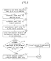
- FIG. 5 is a flow chart depicting the operational flow of another illustrative embodiment of the invention.
- FIG. 6 is a schematic diagram of one illustrative embodiment of a circuit used for time-stamp generation and time stamp synchronization according to the present invention
- FIG. 7 is a block diagram of a CMTS device circuit incorporating the circuit shown in FIG. 6 ;
- FIG. 8 is a timing diagram showing the relationships between various signals transmitted according to one illustrative embodiment of the invention.
- the system 1000 includes one or more headends 1012 including respective cable modem termination systems (CMTS) 1042 ( FIG. 2 ) that are located at a cable company facility and that function as modems to service a large number of subscribers.
- CMTS cable modem termination systems
- Each subscriber has a cable modem (CM) 12 .
- CM cable modem
- the cable modem termination systems 1042 are capable of facilitating bidirectional communication with any desired one of the plurality of cable modems 12 .
- the cable modem termination system (CMTS) 1042 is defined to include that portion of a headend which facilitates communication with a plurality of cable modems 12 .
- a typical cable modem termination system includes one or more burst receivers, a continuous transmitters, and medium access controls (MAC).
- MAC medium access controls
- the cable modem termination system 1042 communicates with the plurality of cable modems 12 via a hybrid fiber coaxial (HFC) network 1010 , wherein optical fiber 1020 provides communication to a plurality of fiber nodes or hubs 1022 , and each fiber node typically serves approximately 500 to 2,000 subscribers.
- the subscribers communicate with the fiber node via a common (or shared) coaxial cable 1028 . It is this sharing of the common coaxial cable which necessitates that the number of cable modems 12 attached thereto be limited so as to mitigate the likelihood of undesirable bit rate reductions which inherently occur when an excessive number of cable modems 12 communicate simultaneously over a single coaxial cable 1028 .
- HFC hybrid fiber coaxial
- the hybrid fiber coaxial network 1010 of a cable modem system 1000 utilizes a point-to-multipoint topology to facilitate communication between each cable modem termination system 1042 and the corresponding cable modems 12 .
- Frequency domain multiple access FDMA
- FDMA Frequency domain multiple access
- TDMA time domain multiple access
- Each cable modem termination system (CMTS) 1042 includes at least one downstream modulator for facilitating the transmission of data communications from the CMTS 1042 to the cable modems 12 .
- each CMTS 1042 includes at least one upstream demodulator for facilitating the reception of data communications from the respective cable modems 12 .
- the downstream modulator(s) preferably utilize a data transmission protocol that provides a relatively high throughput rate, while the upstream demodulators may utilize a data transmission protocol that provides a lower throughput rate.
- each cable modem 12 includes an upstream modulator for facilitating the transmission of data to the corresponding cable modem termination system 1042 and a downstream demodulator for receiving data from the cable modem termination system 1042 .
- Contemporary cable modem systems operate on a plurality of upstream channels and preferably utilize time division multiple access (TDMA) in order to facilitate communication between a plurality of cable modems 12 and a single cable modem termination system 1042 on each upstream channel.
- TDMA time division multiple access
- TDMA Time Division Multiple Access
- MAP information is forwarded on to the cable modems 12 , which are controlled by that MAP information, as is described in more detail below.
- System 20 provides a modular system that can accommodate the diverse needs of cable operators in different geographic regions.
- System 20 includes a plurality of CMTS devices, including one master CMTS device 22 and one or more slave CMTS devices 24 .
- CMTS devices including one master CMTS device 22 and one or more slave CMTS devices 24 .
- the number of slave CMTS devices 24 will vary depending on the requirements of a particular geographic region.
- additional slave CMTS devices 24 may be incorporated into the system 20 .
- system 20 is readily expandable.
- the master CMTS device 22 includes a downstream channel 26 to transmit data to the downstream cable modems 12 being serviced by the master device 22 .
- each CMTS device 22 and 24 includes at least one upstream channel 28 , and preferably plural such channels, to receive data transmitted by the respective cable modems.
- One or more of the slave CMTS devices 24 may also include a downstream channel 26 (shown in dashed lines in FIG. 3 ).
- the master CMTS device 22 is connected to each of the slave CMTS devices 24 by means of a synchronization bus 30 . As is described in greater detail below, master CMTS device 22 is programmed to broadcast certain information over bus 30 for receipt by the respective slave CMTS devices 24 to control the respective slave CMTS devices. In addition, time stamp information for synchronizing the CMTS devices 22 and 24 is broadcast over bus 30 for receipt by all of the CMTS devices 22 and 24 .
- synchronization bus is intended to refer to any path to allow the transmission of data, for example, a peripheral component interface (“PCI”), back-plane bus, four-wire interface, coaxial cable, or even a wireless path.
- PCI peripheral component interface
- synchronization bus is not intended to refer to any particular type of path; rather, it is used herein to refer to any suitable path for the transmission of the below-described data.
- Operation begins at step 50 , with system 20 generating a future time stamp value.
- system 20 polls the master CMTS device 22 for its current counter value, and generates a future time stamp value based on that current counter value.
- the future time stamp value is a value that will be used to synchronize the counter of each CMTS device 22 and 24 .
- system 20 broadcasts the future time stamp value over bus 30 , along with appropriate control data for receipt by the respective devices 22 and 24 .
- the future time stamp value is a 32-bit data word, and the control data precedes the data word and serves to identify the data as corresponding to a future time stamp value.
- CMTS devices 22 and 24 receive the broadcasted data.
- CMTS devices 22 and 24 process the control data to determine that the data packet contains a future time stamp value, and the respective CMTS devices 22 and 24 then store the future time stamp value to an appropriate register.
- master CMTS device 22 stores the future value in a comparison register, while the slave devices 24 store the value in respective load registers.
- system 20 uses conventional software interrupts or polling mechanisms to detect missing time stamp transmissions at the respective CMTS devices 22 and 24 .
- software interrupts may operate to check the respective CMTS devices 22 and 24 to ensure that each transmission was received. In one embodiment, this is accomplished by a software interrupt that reads the value of the TGCVerify register 306 for each CMTS device 22 and 24 .
- master CMTS device 22 determines whether its internal time stamp counter has reached the value of the future time stamp. In one embodiment, device 22 compares the value of its time stamp counter with the future time stamp value stored in its comparison register. Operation remains at query block 56 until master CMTS device 22 determines that in fact its internal counter has reached the transmitted future time stamp value. Operation then proceeds to step 58 , and master CMTS device 22 broadcasts a corresponding control signal over bus 30 to the respective slave CMTS devices 24 . At step 60 , the respective slave CMTS devices 24 receive the control signal and process same to determine that the stored time stamp value must be retrieved. Each slave CMTS device 24 then retrieves the time stamp value from its load register or other suitable location, and loads its counter with that value. Operation then terminates at step 62 .
- the CMTS devices 22 and 24 are all synchronized to the same time stamp value, which provides system redundancy. If one of the CMTS devices 24 fails, one or more of the other devices 24 can assume the failed device's load and process requests from the cable modems 12 that were previously being serviced by the now-unavailable device 24 . As is well known in the art, cable modem systems are very dependent on timing information. If two of the CMTS devices are slightly off in terms of timing, one CMTS device cannot assume the other CMTS device's load without causing the associated cable modems to be affected. Thus, by providing multiple, synchronized CMTS devices, the respective cable modems can be serviced by any of those devices. Thus, system 20 can engage in load balancing and can send commands to transfer the cable modems 12 between the respective downstream channels 26 .
- the synchronization method of FIG. 4 is frequently repeated to continually ensure that the various CMTS devices 22 and 24 remain synchronized with one another.
- the frequency of performing the method depends on the precision of the reference oscillators used.
- each of the CMTS devices 22 and 24 includes its own reference oscillator having a precision on the order of 50 parts per million (“PPM”), in which case a future time stamp value is transmitted on the order of once per millisecond.
- PPM parts per million
- the rate at which the synchronization process is performed will vary depending on many factors, including the system timebase quality. For example, if the reference oscillators are of very high quality, the synchronization process of FIG. 4 may be performed less frequently.
- the same timebase may be used for all slave devices and the master device, in which case the synchronization process may be repeated relatively infrequently, if at all.
- system 20 also controls the sharing of MAP information among the respective CMTS devices 22 and 24 of system 20 .
- MAP information is generated by a component of system 20 (e.g., CPU 311 ), with time slots then being allocated to the respective cable modems, dictating when those cable modems may transmit messages over one of the upstream channels. That time slot information is then transmitted to the cable modems over the respective downstream channels.
- a method for sharing upstream MAP information amongst the respective CMTS devices 22 and 24 .
- each CMTS device 22 and 24 is connected to at least one upstream channel 28 .
- Each of these channels is assigned a unique identifier that is recognized by the component assigning the time slots, as well as by the respective CMTS devices 22 and 24 .
- Operation of the MAP sharing method begins at step 100 , with system 20 assigning time slots for each upstream channel 28 , and generating corresponding MAP information, along with channel identification information for each time slot.
- time slot number one on upstream channel number one may be assigned to cable modem X
- time slot two on channel number one is assigned to cable modem Y
- time slot number one on upstream channel number two is assigned to cable modem Z
- time slot number two on channel number two is assigned to cable modem W.
- each discrete time slot assignment preferably is a data block that includes information to identify 1) the time slot, 2) the upstream channel, and 3) the cable modem.
- such functionality is carried out by CPU 311 .
- the MAP information is transmitted to the master CMTS device 22 , preferably over bus 30 .
- Master CMTS device 22 then forwards the MAP information on to the respective cable modems 12 over downstream channel 26 , at step 104 .
- the cable modems receive the time slot information and store the relevant time slot information in a register until the appropriate time, at which time the cable modems are allowed to transmit information to the CMTS device over the respective upstream channels 28 .
- master CMTS device 22 broadcasts the MAP information to the slave CMTS devices 24 .
- each CMTS device 24 receives the MAP information and analyze the channel identification information for the respective assignments.
- each CMTS device determines whether the channel identification information matches with one of the channels connected to that CMTS device. If so, then operation proceeds to step 112 , and the corresponding assignment is stored by that CMTS device.
- step 114 if the channel identification information does not match with one of the channels connected to a particular CMTS device, then operation proceeds to step 114 and that MAP information is ignored by that particular CMTS device. In that manner, each slave CMTS device 24 only stores the MAP information relevant to it. The irrelevant information is discarded.
- the MAP information may be simultaneously broadcast to each of the CMTS devices 22 and 24 , with master device 22 forwarding the MAP information on to the cable modems 12 , and each CMTS device 22 and 24 then filtering the MAP information and storing the relevant information for the respective CMTS device.
- the MAP information may be transmitted to each CMTS device 22 and 24 that has an associated downstream channel 26 , so that the MAP information can be transmitted to all of the cable modems 12 .
- One of those CMTS devices (for example, the master device 22 ) then broadcasts the MAP information to the other slave devices 24 , and the filtering step is then carried out.
- control data includes data to indicate the type of data being transmitted (either MAP or time stamp value information), control data to alert the slave CMTS devices 24 that a time stamp value is then valid, and end-of-package (EOP) control data to indicate the end of a block of MAP information.
- EOP end-of-package
- the future time stamp value must be transmitted some amount of time before the master device's internal counter reaches the time stamp value.
- the future time stamp value is transmitted between about 8 and about 64 synchronization clock cycles prior to reaching the future value, so as to ensure that the slave devices 24 receive the time stamp value in a timely manner.
- each of the master and slave CMTS devices 22 and 24 includes its own reference oscillator.
- the synchronization process will have to be repeated more or less often. For example, in the case of oscillators with a precision of 50 PPM, it is desirable to repeat the process once per millisecond.
- the respective CMTS devices 22 and 24 can be driven from a single reference oscillator, in which case the respective counters in each CMTS device need not be updated as frequently, if at all. This allows for setting the counter value once, with only periodic checks being done to ensure that the slave devices 24 remain synchronized with the master device 22 .
- each of the master and slave devices 22 and 24 are run from the same oscillator, it is presumed that the respective devices 22 and 24 remain in synchronization with each other for relatively long periods of time.
- the initial synchronization process is identical to that described above in connection with FIG. 4 .
- the synchronization process shown in FIG. 4 need not be frequently repeated.
- CPU 311 is preferably programmed to periodically read the value in TGCVerify register 306 from one or more of the slave devices 24 and to compare that value with the value in register 306 of master device 22 . If the two values are not identical, then the process of FIG. 4 may be repeated to regain synchronization.
- the circuit 200 includes a counter 202 including an accumulator 204 , a pair of multiplexers (MUX) 206 and 207 , and thirty two D-type flip flops 208 (shown schematically) to process the individual bits of a 32-bit time stamp.
- the accumulator 204 increments the output of the flip flops 208 (i.e., the time stamp value of the counter 202 ), and introduces the incremented value to MUX 206 , which also receives the time stamp value from flip flops 208 directly.
- MUX 206 is designed to select the output from flips flops 208 until it is triggered by a rising edge of TikClk introduced to MUX 206 , in which case the signal from accumulator 204 is selected.
- the output of MUX 206 is introduced to MUX 207 , along with a TSLoadVal signal from a TSLoadVal Register 304 ( FIG. 7 ).
- MUX 207 is designed to select the output from MUX 206 until it receives a ld_ts signal pulse, in which case MUX 207 is designed to select the TSLoadVal signal and to output same.
- the output of MUX 207 is introduced to the D inputs of the respective 32 flip flops 208 (one bit per flip flop), which serve to update the value of the local counter upon the next rising edge of the clock input.
- the output of the counter 202 is introduced to a pair of multiplexers 210 and 212 .
- the output of each MUX 210 and 212 is introduced to the D inputs of respective D-type flip flops 214 and 216 , and the Q outputs of each flip flop 214 and 216 define, respectively, TSRegister (TSR) and TGCVerify (TGCV) signals, which are fed back to the respective MUXs 210 and 212 .
- TSR TSRegister
- TGCV TGCVerify
- the current counter value TGC (i.e., the output of flip flops 208 ) is selected by that MUX, and is passed on through the corresponding flip flop as output signal TGCV or TSR.
- Circuit 200 also includes a synchronizer 220 consisting of a plurality of D-type flip flops 222 , 224 , 226 , and 228 arranged in series. Each flip flop preferably receives the 20.48 MHz clock.
- the first flip flop 222 receives a TSSync pulse at its D input, and has its Q output coupled to the D input of flip flop 224 .
- the Q output of flip flop 224 is coupled to the D input of flip flop 226 , and is also coupled to one input of an AND gate 230 .
- the output of flip flop 226 is coupled to an inverted input of AND gate 230 .
- the synchronizer 220 may be used to perform a synchronization technique in which a register may be loaded by logic that uses one clock domain (e.g., 20.48 MHz), and the register may then be read by logic that uses a different clock domain (e.g., 100 MHz). This allows for moving the counter time stamp value from the 20.48 MHz time domain of the circuit 200 into the 100 MHz time domain of the overall system clock.
- the synchronizer 220 receives the TSSync pulse that is generated on the system clock (e.g., 100 MHz), and outputs the TSLatch pulse that is on the TGC time base (e.g., 20.48 MHz).
- the TSSync pulse preferably has a width greater than one clock cycle of the TGC time base.
- the TSSync pulse is synchronized by the synchronizer 220 , which is driven by the TGC clock (e.g., 20.48 MHz).
- the TSSync pulse is generated by the timebase which drives the logic that will read the contents of the register.
- the TSSync pulse is generated a predetermined amount of time prior to the actual read of the contents of the register, and synchronized to provide a rising edge detection by logic driven by the same timebase which also drives the logic that loads the contents of the register.
- Circuit 200 also includes D-type flip flop 232 , which serves to divide the frequency of the 20.48 MHz clock by a factor of two, and supplies the inverted 10.24 MHZ TikClk signal to MUX 206 .
- the TikClk is 1 ⁇ 2 the 20.48 MHz reference oscillator and is centered 1 ⁇ 2 way between TGC transitions. This allows the rising edge of the 10.24 MHz TikClk signal to be exactly centered within the TGC value.
- Circuit 300 includes a comparison register TGCCompReg 302 , a future time stamp register TSLoadValReg 304 , the time stamp generation counter (TGC) 202 , a verify register TGCVerify 306 , and a time stamp register TSRegister 308 .
- Circuit 300 communicates with the system 20 via a DS host interface 309 .
- Circuit 300 may be used in either the master CMTS device 22 , or in the slave CMTS devices 24 , as is described in detail below.
- TGCCompReg 302 serves to hold the future time stamp value for the master CMTS device 22
- TSLoadValReg 304 holds the future time stamp value for each slave CMTS device 24 .
- Each register 302 and 304 receives a TSLoadVal signal from the component generating the future time stamp values, as is described in more detail below.
- the TGC counters 202 serve to continually update the current time stamp value for the corresponding CMTS devices.
- the continually incrementing output of the counter 202 is introduced to AND gate 310 , along with the value in the TGCCompReg 302 .
- a pulse is generated by AND gate 310 which is introduced to the D input of a D-type flip flop 312 , whose Q output then generates a load signal LdTsExt, which is broadcast to each of the slave CMTS devices 24 .
- Each slave CMTS device 24 receives the LdTsExt signal at an OR gate 314 , along with a register command LdTsInt, either of which causes the output of OR gate 314 to go high.
- the output from the OR gate is introduced to synchronizer 316 , which generates the ld_ts signal at the next rising edge of the 20.48 MHz clock signal.
- the ld_ts signal is introduced to counter 202 , which is thereby triggered to retrieve the future time stamp value from register 304 and to set the value of counter 202 to that value to thereby synchronize each slave CMTS device 24 with master CMTS device 22 .
- the value of counter 202 is also introduced to registers 306 and 308 in response to receipt of the TGCV and TSR signals from respective flip flops 210 and 212 ( FIG. 6 ).
- the values in each register 306 and 308 can be verified by respective VerTGC and VerTSR signals received via DS host interface 309 .
- System 20 includes appropriate software for generating the future time stamp value, with such software controlling an appropriate component of system 20 , such as CPU 311 .
- the CPU 311 is controlled by software to poll the counter 202 of master CMTS device 22 for the current time stamp value.
- an appropriate polling signal is transmitted and received by the host interface 309 .
- the signal is passed to a synchronizer 320 , which outputs VerTGC signal on the next rising edge of the 20.48 MHz clock.
- the VerTGC signal is received by MUX 212 ( FIG. 6 ), which then passes the current time stamp value to TGCVerify register 306 , which in turn passes the time stamp value to the CPU 311 through interface 309 .
- the software then controls CPU 311 to take the current time stamp value, add some predetermined number of cycles to that value to generate the future time stamp value, and to pass the signal on to the respective CMTS devices 22 and 24 as TSLoadVal, which is received by the respective registers 302 and 304 . Then, as described above, when the value in register 302 equals the counter value, the LdTsExt pulse is generated by the master CMTS device 22 . Each slave receives the pulse at OR gate 314 , forwards the pulse as signal ld_ts to counter 202 of each slave device 24 , which then takes the value in register 304 and loads that value into counter 202 , to thereby synchronize the respective devices 22 and 24 .
- the slave devices 24 may be one or two clock cycles behind the master device 22 once their counters 202 are updated.
- the value transmitted to the TGCCompReg register 302 is deliberately selected to be one or two cycles behind the value transmitted to the TSLoadVal registers 304 of each slave device 24 . In this manner, by the time the counters in the slave devices 24 have been updated, the time stamp of the master device 22 will have advanced one or two cycles, and the devices 22 and 24 will be synchronized.
- the registers 302 and 304 are combined into a single register, used for both comparison purposes in the master device 22 and for holding the future time stamp value and updating the counter 202 in the respective slave devices 24 .
- the output from AND gate 310 in master device 22 serves as the LdTsExt pulse signal, and is connected directly to the respective registers in the slave devices 24 to immediately cause the counters 202 in the slave devices 24 to be updated to the new time stamp value.
- FIG. 8 there is shown the timing relationships and clock domain properties for the loading, transfer, and verification of TGC values.
- the TGC clock runs at 20.48 MHz, while the system clock Sys_Clk is at 100 MHz.
- a TSSync pulse is generated on a byte number that is a predetermined number of bytes prior to the location of the actual time stamp.
- the TSSync pulse is synchronized by edge detection into the 20.48 MHz domain.
- the resulting TSLatch pulse serves to capture the current TGC value and has that value available in TSRegister 308 a predetermined amount of time before it is needed for insertion into the downstream time-stamped message.
- the TSLatch pulse triggers MUX 210 , such that the next rising edge of the clock causes the value of TSRegister 308 to be updated with the then-current value of counter 202 .
- the value of TSRegister 308 then remains fixed until the next TSLatch pulse is received by MUX 210 .
- This invention is used in a CMTS device disclosed in an application entitled “Method and Apparatus for the Reduction of Upstream Request Processing Latency in a Cable Modem Termination System” Ser. No. 11/121,116, filed on even date herewith by Lisa Denney, Angers Hebsgaard, and Robert J. Lee, the disclosure of which is incorporated fully herein by reference.
- the present invention provides a system and method for maintaining synchronization between multiple CMTS devices.
- the invention allows for the sharing of MAP information between the multiple CMTS devices.
Abstract
Description
Claims (23)
Priority Applications (2)
| Application Number | Priority Date | Filing Date | Title |
|---|---|---|---|
| US11/392,806 US8005072B2 (en) | 1998-10-30 | 2006-03-30 | Synchronization of multiple base stations in a wireless communication system |
| US11/701,509 US7899034B2 (en) | 1998-10-30 | 2007-02-02 | Methods for the synchronization of multiple base stations in a wireless communication system |
Applications Claiming Priority (12)
| Application Number | Priority Date | Filing Date | Title |
|---|---|---|---|
| US10644198P | 1998-10-30 | 1998-10-30 | |
| US10642798P | 1998-10-30 | 1998-10-30 | |
| US10644098P | 1998-10-30 | 1998-10-30 | |
| US10626498P | 1998-10-30 | 1998-10-30 | |
| US10643998P | 1998-10-30 | 1998-10-30 | |
| US10643898P | 1998-10-30 | 1998-10-30 | |
| US15166199P | 1999-08-31 | 1999-08-31 | |
| US43082199A | 1999-10-29 | 1999-10-29 | |
| US09/574,558 US6650624B1 (en) | 1998-10-30 | 2000-05-19 | Cable modem apparatus and method |
| US09/653,155 US6760316B1 (en) | 1998-10-30 | 2000-08-31 | Method and apparatus for the synchronization of multiple cable modem termination system devices |
| US10/856,829 US7035251B2 (en) | 1998-10-30 | 2004-06-01 | Method and apparatus for the synchronization of multiple cable modem termination system devices |
| US11/392,806 US8005072B2 (en) | 1998-10-30 | 2006-03-30 | Synchronization of multiple base stations in a wireless communication system |
Related Parent Applications (1)
| Application Number | Title | Priority Date | Filing Date |
|---|---|---|---|
| US10/856,829 Continuation US7035251B2 (en) | 1998-10-30 | 2004-06-01 | Method and apparatus for the synchronization of multiple cable modem termination system devices |
Related Child Applications (1)
| Application Number | Title | Priority Date | Filing Date |
|---|---|---|---|
| US11/701,509 Continuation US7899034B2 (en) | 1998-10-30 | 2007-02-02 | Methods for the synchronization of multiple base stations in a wireless communication system |
Publications (2)
| Publication Number | Publication Date |
|---|---|
| US20060182148A1 US20060182148A1 (en) | 2006-08-17 |
| US8005072B2 true US8005072B2 (en) | 2011-08-23 |
Family
ID=32601267
Family Applications (4)
| Application Number | Title | Priority Date | Filing Date |
|---|---|---|---|
| US09/653,155 Expired - Lifetime US6760316B1 (en) | 1998-10-30 | 2000-08-31 | Method and apparatus for the synchronization of multiple cable modem termination system devices |
| US10/856,829 Expired - Lifetime US7035251B2 (en) | 1998-10-30 | 2004-06-01 | Method and apparatus for the synchronization of multiple cable modem termination system devices |
| US11/392,806 Expired - Fee Related US8005072B2 (en) | 1998-10-30 | 2006-03-30 | Synchronization of multiple base stations in a wireless communication system |
| US11/701,509 Expired - Fee Related US7899034B2 (en) | 1998-10-30 | 2007-02-02 | Methods for the synchronization of multiple base stations in a wireless communication system |
Family Applications Before (2)
| Application Number | Title | Priority Date | Filing Date |
|---|---|---|---|
| US09/653,155 Expired - Lifetime US6760316B1 (en) | 1998-10-30 | 2000-08-31 | Method and apparatus for the synchronization of multiple cable modem termination system devices |
| US10/856,829 Expired - Lifetime US7035251B2 (en) | 1998-10-30 | 2004-06-01 | Method and apparatus for the synchronization of multiple cable modem termination system devices |
Family Applications After (1)
| Application Number | Title | Priority Date | Filing Date |
|---|---|---|---|
| US11/701,509 Expired - Fee Related US7899034B2 (en) | 1998-10-30 | 2007-02-02 | Methods for the synchronization of multiple base stations in a wireless communication system |
Country Status (1)
| Country | Link |
|---|---|
| US (4) | US6760316B1 (en) |
Families Citing this family (39)
| Publication number | Priority date | Publication date | Assignee | Title |
|---|---|---|---|---|
| US6760316B1 (en) * | 1998-10-30 | 2004-07-06 | Broadcom Corporation | Method and apparatus for the synchronization of multiple cable modem termination system devices |
| US6834057B1 (en) * | 1999-02-12 | 2004-12-21 | Broadcom Corporation | Cable modem system with sample and packet synchronization |
| US6751191B1 (en) | 1999-06-29 | 2004-06-15 | Cisco Technology, Inc. | Load sharing and redundancy scheme |
| US6909715B1 (en) * | 1999-08-31 | 2005-06-21 | Broadcom Corporation | Method and apparatus for the reduction of upstream request processing latency in a cable modem termination system |
| US7058007B1 (en) * | 2000-01-18 | 2006-06-06 | Cisco Technology, Inc. | Method for a cable modem to rapidly switch to a backup CMTS |
| US7068712B1 (en) * | 2000-01-18 | 2006-06-27 | Cisco Technology, Inc. | Cable network redundancy architecture |
| US6839829B1 (en) | 2000-01-18 | 2005-01-04 | Cisco Technology, Inc. | Routing protocol based redundancy design for shared-access networks |
| US6944188B2 (en) | 2001-02-21 | 2005-09-13 | Wi-Lan, Inc. | Synchronizing clocks across a communication link |
| US7881208B1 (en) | 2001-06-18 | 2011-02-01 | Cisco Technology, Inc. | Gateway load balancing protocol |
| US7177324B1 (en) * | 2001-07-12 | 2007-02-13 | At&T Corp. | Network having bandwidth sharing |
| US7336680B2 (en) * | 2001-09-18 | 2008-02-26 | Scientific-Atlanta, Inc. | Multi-carrier frequency-division multiplexing (FDM) architecture for high speed digital service |
| US20030058893A1 (en) * | 2001-09-27 | 2003-03-27 | Broadcom Corporation | Synchronization of multiple cable modem termination systems |
| US7206327B2 (en) * | 2002-05-17 | 2007-04-17 | Broadcom Corporation | Method and circuit for insertion of time stamp into real time data |
| US7372872B2 (en) * | 2002-05-20 | 2008-05-13 | Broadcom Corporation | System and method for monitoring upstream and downstream transmissions in cable modern system |
| US7174376B1 (en) | 2002-06-28 | 2007-02-06 | Cisco Technology, Inc. | IP subnet sharing technique implemented without using bridging or routing protocols |
| US7397846B1 (en) * | 2002-10-03 | 2008-07-08 | Juniper Networks, Inc. | Flexible upstream resource sharing in cable modem systems |
| US7583704B1 (en) * | 2003-06-10 | 2009-09-01 | Carl Walker | Synchronizing separated upstream and downstream channels of cable modem termination systems |
| GB2430570B (en) * | 2004-04-07 | 2009-01-21 | Siemens Ag | Method and apparatus for determining a deviation between clock pulse devices |
| US7885182B2 (en) * | 2004-05-14 | 2011-02-08 | Arris Group, Inc. | Method for fast recovery from ring protection switches on DOCSIS networks |
| US20080049794A1 (en) * | 2005-01-13 | 2008-02-28 | Raul Assia | Device, System and Method of Communicating Between Circuit Switch Interfaces Over an Analog Modulation Communication Network |
| US7899894B2 (en) | 2006-08-30 | 2011-03-01 | International Business Machines Corporation | Coordinated timing network configuration parameter update procedure |
| US8738792B2 (en) * | 2007-01-31 | 2014-05-27 | International Business Machines Corporation | Server time protocol messages and methods |
| US9112626B2 (en) * | 2007-01-31 | 2015-08-18 | International Business Machines Corporation | Employing configuration information to determine the role of a server in a coordinated timing network |
| US7689718B2 (en) * | 2007-01-31 | 2010-03-30 | International Business Machines Corporation | Channel subsystem server time protocol commands and system therefor |
| US7843810B2 (en) * | 2007-07-30 | 2010-11-30 | Cisco Technology, Inc. | Keeping modems online upon N+1 switchover in cable modem termination systems |
| EP2053822A1 (en) * | 2007-10-23 | 2009-04-29 | Koninklijke KPN N.V. | Method and system for synchronizing the output of a group of end-terminals |
| EP2206316B1 (en) * | 2007-10-23 | 2013-08-14 | Koninklijke KPN N.V. | Method and system for synchronizing a group of end-terminals |
| US7839773B2 (en) * | 2008-03-14 | 2010-11-23 | Cisco Technology, Inc. | Modem timing offset compensation for line card redundancy failover |
| US7925916B2 (en) | 2008-04-10 | 2011-04-12 | International Business Machines Corporation | Failsafe recovery facility in a coordinated timing network |
| US8416811B2 (en) * | 2008-04-10 | 2013-04-09 | International Business Machines Corporation | Coordinated timing network having servers of different capabilities |
| US20090310522A1 (en) * | 2008-06-12 | 2009-12-17 | Bertonis James G | Wireless synchronization of base stations |
| US7873862B2 (en) * | 2008-10-21 | 2011-01-18 | International Business Machines Corporation | Maintaining a primary time server as the current time server in response to failure of time code receivers of the primary time server |
| EP2382829B1 (en) * | 2009-01-23 | 2014-10-29 | Kapsch CarrierCom France S.A.S. | Method of synchronisation within a base station system |
| CN105898857B (en) * | 2009-06-23 | 2021-05-07 | 北京三星通信技术研究有限公司 | Data synchronization method and system |
| JP5970958B2 (en) * | 2012-05-22 | 2016-08-17 | 富士通株式会社 | Information processing apparatus, delay difference measurement method, and delay difference measurement program |
| US9553756B2 (en) * | 2012-06-01 | 2017-01-24 | Koninklijke Kpn N.V. | Fingerprint-based inter-destination media synchronization |
| CN104243079A (en) * | 2014-10-09 | 2014-12-24 | 四川省绵阳西南自动化研究所 | Microsecond clock synchronization method for real-time Ethernet |
| CN106454474B (en) * | 2016-10-08 | 2019-08-06 | Oppo广东移动通信有限公司 | Multimedia synchronous plays method, apparatus and system |
| US11784781B2 (en) * | 2021-06-07 | 2023-10-10 | Abdul-Karim Lakhani | Full duplex wireless communication system with single master clock |
Citations (78)
| Publication number | Priority date | Publication date | Assignee | Title |
|---|---|---|---|---|
| US3839678A (en) | 1973-02-26 | 1974-10-01 | Zenith Radio Corp | Crystal controlled all-band television tuning system |
| US4383272A (en) | 1981-04-13 | 1983-05-10 | Bell Telephone Laboratories, Incorporated | Video signal interpolation using motion estimation |
| US4520490A (en) | 1983-08-05 | 1985-05-28 | At&T Information Systems Inc. | Differentially nonlinear convolutional channel coding with expanded set of signalling alphabets |
| US4617676A (en) | 1984-09-04 | 1986-10-14 | At&T Bell Laboratories | Predictive communication system filtering arrangement |
| EP0353779A2 (en) | 1988-08-05 | 1990-02-07 | Nec Corporation | Preamble detection circuit for digital communications system |
| US4928272A (en) | 1988-05-23 | 1990-05-22 | Matsushita Electric Industrial Co., Ltd. | Two-way CATV system using frequency division multiplexing |
| US4941154A (en) | 1989-05-30 | 1990-07-10 | At&T Bell Laboratories | Trellis coding method and arrangement for fractional bit rates |
| US4958226A (en) | 1989-09-27 | 1990-09-18 | At&T Bell Laboratories | Conditional motion compensated interpolation of digital motion video |
| US5059926A (en) * | 1991-03-13 | 1991-10-22 | Motorola, Inc. | Frequency synchronization apparatus |
| US5115453A (en) | 1990-10-01 | 1992-05-19 | At&T Bell Laboratories | Technique for designing a multidimensional signaling scheme |
| EP0548318A1 (en) | 1991-07-15 | 1993-06-30 | MERCK PATENT GmbH | Liquid-crystal material |
| US5227878A (en) | 1991-11-15 | 1993-07-13 | At&T Bell Laboratories | Adaptive coding and decoding of frames and fields of video |
| US5293380A (en) * | 1989-12-27 | 1994-03-08 | Nec Corporation | Frame synchronization system among multiple radio base stations for TDMA digital mobile communications system |
| US5339384A (en) | 1992-02-18 | 1994-08-16 | At&T Bell Laboratories | Code-excited linear predictive coding with low delay for speech or audio signals |
| US5341457A (en) | 1988-12-30 | 1994-08-23 | At&T Bell Laboratories | Perceptual coding of audio signals |
| US5390216A (en) * | 1991-11-02 | 1995-02-14 | Robert Bosch Gmbh | Synchronization method for a mobile radiotelephone |
| US5488633A (en) | 1993-06-14 | 1996-01-30 | At&T Corp. | Intersymbol interference channel coding scheme |
| US5524135A (en) * | 1994-02-14 | 1996-06-04 | Sony Corporation | Method and apparatus for secure downloading of operational information into a wireless communications device |
| EP0727883A2 (en) | 1995-02-10 | 1996-08-21 | Kabushiki Kaisha Toshiba | Information communication network system, central information communication control device and information communication device used in the system, information sending method, and modulation method |
| US5579513A (en) | 1991-12-18 | 1996-11-26 | Siemens Aktiengesellschaft | Method for monitoring the synchronization of clocks in computer networks |
| EP0748120A1 (en) | 1995-06-07 | 1996-12-11 | General Instrument Corporation | Interference cancellation system for CATV return transmissions |
| WO1997010553A1 (en) | 1995-09-11 | 1997-03-20 | Motorola Inc. | Device and method for adaptive narrowband interference suppresson in multiple-access communication |
| EP0768769A2 (en) | 1995-10-16 | 1997-04-16 | General Instrument Corporation Of Delaware | Method and apparatus for supporting TDMA operation over hybrid fiber coaxial (HFC) or other channels |
| WO1997015129A1 (en) | 1995-10-19 | 1997-04-24 | Cabletron Systems, Inc. | Method and apparatus for network access control with implicit ranging and dynamically assigned time slots |
| WO1997016046A1 (en) | 1995-10-24 | 1997-05-01 | General Instrument Corporation | Variable length burst transmission over the physical layer of a multilayer transmission format |
| US5627938A (en) | 1992-03-02 | 1997-05-06 | Lucent Technologies Inc. | Rate loop processor for perceptual encoder/decoder |
| US5631846A (en) | 1995-02-28 | 1997-05-20 | Lucent Technologies Inc. | Upstream communications for interactive networks |
| US5640424A (en) | 1995-05-16 | 1997-06-17 | Interstate Electronics Corporation | Direct downconverter circuit for demodulator in digital data transmission system |
| US5648962A (en) * | 1993-05-25 | 1997-07-15 | Nokia Telecommunications Oy | Base station in a cellular radio system and a cellular radio system |
| US5652574A (en) * | 1993-01-06 | 1997-07-29 | William H. Berkman | Dynamically addressable communications system and method |
| GB2312362A (en) | 1996-04-20 | 1997-10-22 | Northern Telecom Ltd | Channel equalisation in telecomms system |
| WO1997041691A1 (en) | 1996-04-29 | 1997-11-06 | Philips Electronics N.V. | Method and apparatus for combatting ingress and multipath in a catv return channel |
| US5696765A (en) | 1995-02-28 | 1997-12-09 | General Instrument Corporation | Configurable hybrid medium access control for cable metropolitan area networks |
| US5703539A (en) | 1993-12-17 | 1997-12-30 | Motorola, Inc. | Apparatus and method for controlling the loop bandwidth of a phase locked loop |
| US5710765A (en) | 1995-11-06 | 1998-01-20 | Matsushita Electric Industrial Co., Ltd. | Method and apparatus for increasing the system efficiency of a TDMA system by reducing time slot guard time |
| US5790806A (en) | 1996-04-03 | 1998-08-04 | Scientific-Atlanta, Inc. | Cable data network architecture |
| JPH10243371A (en) | 1997-02-27 | 1998-09-11 | Toshiba Corp | Equipment and method for data communication |
| US5912895A (en) | 1996-05-01 | 1999-06-15 | Northern Telecom Limited | Information network access apparatus and methods for communicating information packets via telephone lines |
| US5943604A (en) | 1997-10-31 | 1999-08-24 | Cisco Technology, Inc. | Echo device method for locating upstream ingress noise gaps at cable television head ends |
| US6005854A (en) | 1997-08-08 | 1999-12-21 | Cwill Telecommunication, Inc. | Synchronous wireless access protocol method and apparatus |
| US6028860A (en) | 1996-10-23 | 2000-02-22 | Com21, Inc. | Prioritized virtual connection transmissions in a packet to ATM cell cable network |
| US6088591A (en) * | 1996-06-28 | 2000-07-11 | Aironet Wireless Communications, Inc. | Cellular system hand-off protocol |
| US6108713A (en) | 1997-02-11 | 2000-08-22 | Xaqti Corporation | Media access control architectures and network management systems |
| US6137793A (en) | 1997-12-05 | 2000-10-24 | Com21, Inc. | Reverse path multiplexer for use in high speed data transmissions |
| WO2001017167A2 (en) | 1999-08-31 | 2001-03-08 | Broadcom Corporation | Method and apparatus for the synchronization of multiple cable modem termination system devices |
| US6230326B1 (en) | 1998-07-30 | 2001-05-08 | Nortel Networks Limited | Method and apparatus for initialization of a cable modem |
| US6236678B1 (en) | 1998-10-30 | 2001-05-22 | Broadcom Corporation | Method and apparatus for converting between byte lengths and burdened burst lengths in a high speed cable modem |
| US6298098B1 (en) | 1996-04-09 | 2001-10-02 | Intel Corporation | Burst demodulator for use in high speed bidirectional digital cable transmission system |
| US20020012343A1 (en) | 2000-04-07 | 2002-01-31 | Holloway John T. | Transceiver method and signal therefor embodied in a carrier wave for a frame-based communications network |
| US6349138B1 (en) | 1996-06-14 | 2002-02-19 | Lucent Technologies Inc. | Method and apparatus for digital transmission incorporating scrambling and forward error correction while preventing bit error spreading associated with descrambling |
| US6353604B2 (en) | 1998-05-06 | 2002-03-05 | Terayon Communications Systems, Inc. | Apparatus and method for synchronizing an SCDMA upstream or any other type upstream to an MCNS downstream or any other type downstream with a different clock rate than the upstream |
| US20020038461A1 (en) | 2000-04-19 | 2002-03-28 | Gerard White | Radio-frequency communications redundancy |
| US6385773B1 (en) | 1999-01-07 | 2002-05-07 | Cisco Techology, Inc. | Method and apparatus for upstream frequency channel transition |
| US20020066110A1 (en) | 2000-11-29 | 2002-05-30 | Cloonan Thomas J. | Method and apparatus for preventing re-ranging and re-registration of cable modems during protection switching between active and spare cable interface cards in a cable modem termination system |
| US20020088003A1 (en) | 2000-06-27 | 2002-07-04 | Dror Salee | MAC redundancy in cable network headend |
| US6449291B1 (en) | 1998-11-24 | 2002-09-10 | 3Com Corporation | Method and apparatus for time synchronization in a communication system |
| US6510162B1 (en) | 1998-05-27 | 2003-01-21 | 3Com Corporation | System and method for managing channel usage in a data over cable system |
| US6526070B1 (en) | 1999-10-09 | 2003-02-25 | Conexant Systems, Inc. | Method and apparatus for upstream burst transmissions synchronization in cable modems |
| US20030058893A1 (en) | 2001-09-27 | 2003-03-27 | Broadcom Corporation | Synchronization of multiple cable modem termination systems |
| US6583825B1 (en) | 1994-11-07 | 2003-06-24 | Index Systems, Inc. | Method and apparatus for transmitting and downloading setup information |
| US6606352B2 (en) | 1999-01-15 | 2003-08-12 | Broadcom Corporation | Method and apparatus for converting between byte lengths and burdened burst lengths in a high speed modem |
| US6636485B1 (en) | 1998-05-14 | 2003-10-21 | 3Com Corporation | Method and system for providing quality-of-service in a data-over-cable system |
| US6647070B1 (en) | 1998-09-10 | 2003-11-11 | Texas Instruments Incorporated | Method and apparatus for combating impulse noise in digital communications channels |
| US6647069B1 (en) | 1998-05-01 | 2003-11-11 | Texas Instruments Incorporated | Method and apparatus for capacity increase and enhanced communications performance in CATV networks |
| US6650698B1 (en) | 1999-09-29 | 2003-11-18 | Conexant Systems, Inc. | Non-linear equalization for the upstream data connection of 56K PCM modems |
| US6650624B1 (en) | 1998-10-30 | 2003-11-18 | Broadcom Corporation | Cable modem apparatus and method |
| US6760316B1 (en) | 1998-10-30 | 2004-07-06 | Broadcom Corporation | Method and apparatus for the synchronization of multiple cable modem termination system devices |
| US6819682B1 (en) | 1999-09-03 | 2004-11-16 | Broadcom Corporation | System and method for the synchronization and distribution of telephony timing information in a cable modem network |
| US6853680B1 (en) | 2000-05-10 | 2005-02-08 | Bigband Networks Bas, Inc. | System and process for embedded cable modem in a cable modem termination system to enable diagnostics and monitoring |
| US6909715B1 (en) | 1999-08-31 | 2005-06-21 | Broadcom Corporation | Method and apparatus for the reduction of upstream request processing latency in a cable modem termination system |
| US6961314B1 (en) | 1998-10-30 | 2005-11-01 | Broadcom Corporation | Burst receiver for cable modem system |
| US20060088056A1 (en) | 1998-10-30 | 2006-04-27 | Broadcom Corporation | Data packet fragmentation in a cable modem system |
| US7058007B1 (en) | 2000-01-18 | 2006-06-06 | Cisco Technology, Inc. | Method for a cable modem to rapidly switch to a backup CMTS |
| US7065779B1 (en) | 1999-10-13 | 2006-06-20 | Cisco Technology, Inc. | Technique for synchronizing multiple access controllers at the head end of an access network |
| US7072360B2 (en) | 2000-09-22 | 2006-07-04 | Narad Networks, Inc. | Network architecture for intelligent network elements |
| US7139923B1 (en) | 2001-06-27 | 2006-11-21 | Cisco Technology, Inc. | Technique for synchronizing network devices in an access data network |
| US7146630B2 (en) | 2000-09-22 | 2006-12-05 | Narad Networks, Inc. | Broadband system with intelligent network devices |
| US7372872B2 (en) | 2002-05-20 | 2008-05-13 | Broadcom Corporation | System and method for monitoring upstream and downstream transmissions in cable modern system |
-
2000
- 2000-08-31 US US09/653,155 patent/US6760316B1/en not_active Expired - Lifetime
-
2004
- 2004-06-01 US US10/856,829 patent/US7035251B2/en not_active Expired - Lifetime
-
2006
- 2006-03-30 US US11/392,806 patent/US8005072B2/en not_active Expired - Fee Related
-
2007
- 2007-02-02 US US11/701,509 patent/US7899034B2/en not_active Expired - Fee Related
Patent Citations (94)
| Publication number | Priority date | Publication date | Assignee | Title |
|---|---|---|---|---|
| US3839678A (en) | 1973-02-26 | 1974-10-01 | Zenith Radio Corp | Crystal controlled all-band television tuning system |
| US4383272A (en) | 1981-04-13 | 1983-05-10 | Bell Telephone Laboratories, Incorporated | Video signal interpolation using motion estimation |
| US4520490A (en) | 1983-08-05 | 1985-05-28 | At&T Information Systems Inc. | Differentially nonlinear convolutional channel coding with expanded set of signalling alphabets |
| US4617676A (en) | 1984-09-04 | 1986-10-14 | At&T Bell Laboratories | Predictive communication system filtering arrangement |
| US4928272A (en) | 1988-05-23 | 1990-05-22 | Matsushita Electric Industrial Co., Ltd. | Two-way CATV system using frequency division multiplexing |
| EP0353779A2 (en) | 1988-08-05 | 1990-02-07 | Nec Corporation | Preamble detection circuit for digital communications system |
| US5341457A (en) | 1988-12-30 | 1994-08-23 | At&T Bell Laboratories | Perceptual coding of audio signals |
| US4941154A (en) | 1989-05-30 | 1990-07-10 | At&T Bell Laboratories | Trellis coding method and arrangement for fractional bit rates |
| US4958226A (en) | 1989-09-27 | 1990-09-18 | At&T Bell Laboratories | Conditional motion compensated interpolation of digital motion video |
| US5293380A (en) * | 1989-12-27 | 1994-03-08 | Nec Corporation | Frame synchronization system among multiple radio base stations for TDMA digital mobile communications system |
| US5115453A (en) | 1990-10-01 | 1992-05-19 | At&T Bell Laboratories | Technique for designing a multidimensional signaling scheme |
| US5059926A (en) * | 1991-03-13 | 1991-10-22 | Motorola, Inc. | Frequency synchronization apparatus |
| EP0548318A1 (en) | 1991-07-15 | 1993-06-30 | MERCK PATENT GmbH | Liquid-crystal material |
| US5390216A (en) * | 1991-11-02 | 1995-02-14 | Robert Bosch Gmbh | Synchronization method for a mobile radiotelephone |
| US5227878A (en) | 1991-11-15 | 1993-07-13 | At&T Bell Laboratories | Adaptive coding and decoding of frames and fields of video |
| US5579513A (en) | 1991-12-18 | 1996-11-26 | Siemens Aktiengesellschaft | Method for monitoring the synchronization of clocks in computer networks |
| US5339384A (en) | 1992-02-18 | 1994-08-16 | At&T Bell Laboratories | Code-excited linear predictive coding with low delay for speech or audio signals |
| US5627938A (en) | 1992-03-02 | 1997-05-06 | Lucent Technologies Inc. | Rate loop processor for perceptual encoder/decoder |
| US5652574A (en) * | 1993-01-06 | 1997-07-29 | William H. Berkman | Dynamically addressable communications system and method |
| US5648962A (en) * | 1993-05-25 | 1997-07-15 | Nokia Telecommunications Oy | Base station in a cellular radio system and a cellular radio system |
| US5488633A (en) | 1993-06-14 | 1996-01-30 | At&T Corp. | Intersymbol interference channel coding scheme |
| US5703539A (en) | 1993-12-17 | 1997-12-30 | Motorola, Inc. | Apparatus and method for controlling the loop bandwidth of a phase locked loop |
| US5524135A (en) * | 1994-02-14 | 1996-06-04 | Sony Corporation | Method and apparatus for secure downloading of operational information into a wireless communications device |
| US6583825B1 (en) | 1994-11-07 | 2003-06-24 | Index Systems, Inc. | Method and apparatus for transmitting and downloading setup information |
| EP0727883A2 (en) | 1995-02-10 | 1996-08-21 | Kabushiki Kaisha Toshiba | Information communication network system, central information communication control device and information communication device used in the system, information sending method, and modulation method |
| US5631846A (en) | 1995-02-28 | 1997-05-20 | Lucent Technologies Inc. | Upstream communications for interactive networks |
| US5696765A (en) | 1995-02-28 | 1997-12-09 | General Instrument Corporation | Configurable hybrid medium access control for cable metropolitan area networks |
| US5640424A (en) | 1995-05-16 | 1997-06-17 | Interstate Electronics Corporation | Direct downconverter circuit for demodulator in digital data transmission system |
| EP0748120A1 (en) | 1995-06-07 | 1996-12-11 | General Instrument Corporation | Interference cancellation system for CATV return transmissions |
| WO1997010553A1 (en) | 1995-09-11 | 1997-03-20 | Motorola Inc. | Device and method for adaptive narrowband interference suppresson in multiple-access communication |
| EP0768769A2 (en) | 1995-10-16 | 1997-04-16 | General Instrument Corporation Of Delaware | Method and apparatus for supporting TDMA operation over hybrid fiber coaxial (HFC) or other channels |
| WO1997015129A1 (en) | 1995-10-19 | 1997-04-24 | Cabletron Systems, Inc. | Method and apparatus for network access control with implicit ranging and dynamically assigned time slots |
| WO1997016046A1 (en) | 1995-10-24 | 1997-05-01 | General Instrument Corporation | Variable length burst transmission over the physical layer of a multilayer transmission format |
| US5710765A (en) | 1995-11-06 | 1998-01-20 | Matsushita Electric Industrial Co., Ltd. | Method and apparatus for increasing the system efficiency of a TDMA system by reducing time slot guard time |
| US5790806A (en) | 1996-04-03 | 1998-08-04 | Scientific-Atlanta, Inc. | Cable data network architecture |
| US6298098B1 (en) | 1996-04-09 | 2001-10-02 | Intel Corporation | Burst demodulator for use in high speed bidirectional digital cable transmission system |
| GB2312362A (en) | 1996-04-20 | 1997-10-22 | Northern Telecom Ltd | Channel equalisation in telecomms system |
| WO1997041691A1 (en) | 1996-04-29 | 1997-11-06 | Philips Electronics N.V. | Method and apparatus for combatting ingress and multipath in a catv return channel |
| US5881363A (en) | 1996-04-29 | 1999-03-09 | Philips Electronics North America | Method and apparatus for combatting ingress and multipath in a CATV return channel |
| US5912895A (en) | 1996-05-01 | 1999-06-15 | Northern Telecom Limited | Information network access apparatus and methods for communicating information packets via telephone lines |
| US6349138B1 (en) | 1996-06-14 | 2002-02-19 | Lucent Technologies Inc. | Method and apparatus for digital transmission incorporating scrambling and forward error correction while preventing bit error spreading associated with descrambling |
| US6088591A (en) * | 1996-06-28 | 2000-07-11 | Aironet Wireless Communications, Inc. | Cellular system hand-off protocol |
| US6028860A (en) | 1996-10-23 | 2000-02-22 | Com21, Inc. | Prioritized virtual connection transmissions in a packet to ATM cell cable network |
| US6108713A (en) | 1997-02-11 | 2000-08-22 | Xaqti Corporation | Media access control architectures and network management systems |
| JPH10243371A (en) | 1997-02-27 | 1998-09-11 | Toshiba Corp | Equipment and method for data communication |
| US6005854A (en) | 1997-08-08 | 1999-12-21 | Cwill Telecommunication, Inc. | Synchronous wireless access protocol method and apparatus |
| US6032019A (en) | 1997-10-31 | 2000-02-29 | Cisco Technologies, Inc. | Echo device method for locating upstream ingress noise gaps at cable television head ends |
| US5943604A (en) | 1997-10-31 | 1999-08-24 | Cisco Technology, Inc. | Echo device method for locating upstream ingress noise gaps at cable television head ends |
| US6137793A (en) | 1997-12-05 | 2000-10-24 | Com21, Inc. | Reverse path multiplexer for use in high speed data transmissions |
| US6647069B1 (en) | 1998-05-01 | 2003-11-11 | Texas Instruments Incorporated | Method and apparatus for capacity increase and enhanced communications performance in CATV networks |
| US6353604B2 (en) | 1998-05-06 | 2002-03-05 | Terayon Communications Systems, Inc. | Apparatus and method for synchronizing an SCDMA upstream or any other type upstream to an MCNS downstream or any other type downstream with a different clock rate than the upstream |
| US6636485B1 (en) | 1998-05-14 | 2003-10-21 | 3Com Corporation | Method and system for providing quality-of-service in a data-over-cable system |
| US6510162B1 (en) | 1998-05-27 | 2003-01-21 | 3Com Corporation | System and method for managing channel usage in a data over cable system |
| US6230326B1 (en) | 1998-07-30 | 2001-05-08 | Nortel Networks Limited | Method and apparatus for initialization of a cable modem |
| US6647070B1 (en) | 1998-09-10 | 2003-11-11 | Texas Instruments Incorporated | Method and apparatus for combating impulse noise in digital communications channels |
| US7103065B1 (en) | 1998-10-30 | 2006-09-05 | Broadcom Corporation | Data packet fragmentation in a cable modem system |
| US6965616B1 (en) | 1998-10-30 | 2005-11-15 | Broadcom Corporation | Network data transmission synchronization system and method |
| US7120123B1 (en) | 1998-10-30 | 2006-10-10 | Broadcom Corporation | Pre-equalization technique for upstream communication between cable modem and headend |
| US20060088056A1 (en) | 1998-10-30 | 2006-04-27 | Broadcom Corporation | Data packet fragmentation in a cable modem system |
| US7035251B2 (en) | 1998-10-30 | 2006-04-25 | Broadcom Corporation | Method and apparatus for the synchronization of multiple cable modem termination system devices |
| US7139283B2 (en) | 1998-10-30 | 2006-11-21 | Broadcom Corporation | Robust techniques for optimal upstream communication between cable modem subscribers and a headend |
| US20070109995A1 (en) | 1998-10-30 | 2007-05-17 | Broadcom Corporation | Compensating for noise in a wireless communication system |
| US6961314B1 (en) | 1998-10-30 | 2005-11-01 | Broadcom Corporation | Burst receiver for cable modem system |
| US6650624B1 (en) | 1998-10-30 | 2003-11-18 | Broadcom Corporation | Cable modem apparatus and method |
| US6236678B1 (en) | 1998-10-30 | 2001-05-22 | Broadcom Corporation | Method and apparatus for converting between byte lengths and burdened burst lengths in a high speed cable modem |
| US20070086484A1 (en) | 1998-10-30 | 2007-04-19 | Broadcom Corporation | Data packet fragmentation in a wireless communication system |
| US20070036176A1 (en) | 1998-10-30 | 2007-02-15 | Broadcom Corporation | Methods to compensate for noise in a wireless communication system |
| US6760316B1 (en) | 1998-10-30 | 2004-07-06 | Broadcom Corporation | Method and apparatus for the synchronization of multiple cable modem termination system devices |
| US6449291B1 (en) | 1998-11-24 | 2002-09-10 | 3Com Corporation | Method and apparatus for time synchronization in a communication system |
| US6385773B1 (en) | 1999-01-07 | 2002-05-07 | Cisco Techology, Inc. | Method and apparatus for upstream frequency channel transition |
| US6928109B2 (en) | 1999-01-15 | 2005-08-09 | Broadcom Corporation | Method and apparatus for converting between byte lengths and burdened burst lengths in a broadband communication system |
| US6606352B2 (en) | 1999-01-15 | 2003-08-12 | Broadcom Corporation | Method and apparatus for converting between byte lengths and burdened burst lengths in a high speed modem |
| US6909715B1 (en) | 1999-08-31 | 2005-06-21 | Broadcom Corporation | Method and apparatus for the reduction of upstream request processing latency in a cable modem termination system |
| WO2001017167A2 (en) | 1999-08-31 | 2001-03-08 | Broadcom Corporation | Method and apparatus for the synchronization of multiple cable modem termination system devices |
| US6819682B1 (en) | 1999-09-03 | 2004-11-16 | Broadcom Corporation | System and method for the synchronization and distribution of telephony timing information in a cable modem network |
| US7339956B2 (en) | 1999-09-03 | 2008-03-04 | Broadcom Corporation | System and method for the synchronization and distribution of telephony timing information in a cable modem network |
| US20050053098A1 (en) | 1999-09-03 | 2005-03-10 | Broadcom Corporation | System and method for the synchronization and distribution of telephony timing information in a cable modem network |
| US6650698B1 (en) | 1999-09-29 | 2003-11-18 | Conexant Systems, Inc. | Non-linear equalization for the upstream data connection of 56K PCM modems |
| US6526070B1 (en) | 1999-10-09 | 2003-02-25 | Conexant Systems, Inc. | Method and apparatus for upstream burst transmissions synchronization in cable modems |
| US7065779B1 (en) | 1999-10-13 | 2006-06-20 | Cisco Technology, Inc. | Technique for synchronizing multiple access controllers at the head end of an access network |
| US7058007B1 (en) | 2000-01-18 | 2006-06-06 | Cisco Technology, Inc. | Method for a cable modem to rapidly switch to a backup CMTS |
| US20020012343A1 (en) | 2000-04-07 | 2002-01-31 | Holloway John T. | Transceiver method and signal therefor embodied in a carrier wave for a frame-based communications network |
| US7000031B2 (en) | 2000-04-07 | 2006-02-14 | Broadcom Corporation | Method of providing synchronous transport of packets between asynchronous network nodes in a frame-based communications network |
| US20020038461A1 (en) | 2000-04-19 | 2002-03-28 | Gerard White | Radio-frequency communications redundancy |
| US6853680B1 (en) | 2000-05-10 | 2005-02-08 | Bigband Networks Bas, Inc. | System and process for embedded cable modem in a cable modem termination system to enable diagnostics and monitoring |
| US20020088003A1 (en) | 2000-06-27 | 2002-07-04 | Dror Salee | MAC redundancy in cable network headend |
| US7072360B2 (en) | 2000-09-22 | 2006-07-04 | Narad Networks, Inc. | Network architecture for intelligent network elements |
| US7146630B2 (en) | 2000-09-22 | 2006-12-05 | Narad Networks, Inc. | Broadband system with intelligent network devices |
| US20020066110A1 (en) | 2000-11-29 | 2002-05-30 | Cloonan Thomas J. | Method and apparatus for preventing re-ranging and re-registration of cable modems during protection switching between active and spare cable interface cards in a cable modem termination system |
| US7139923B1 (en) | 2001-06-27 | 2006-11-21 | Cisco Technology, Inc. | Technique for synchronizing network devices in an access data network |
| EP1449375A1 (en) | 2001-09-27 | 2004-08-25 | Broadcom Corporation | Synchronization of multiple cable modem termination systems |
| WO2003028374A1 (en) | 2001-09-27 | 2003-04-03 | Broadcom Corporation | Synchronization of multiple cable modem termination systems |
| US20030058893A1 (en) | 2001-09-27 | 2003-03-27 | Broadcom Corporation | Synchronization of multiple cable modem termination systems |
| US7372872B2 (en) | 2002-05-20 | 2008-05-13 | Broadcom Corporation | System and method for monitoring upstream and downstream transmissions in cable modern system |
Non-Patent Citations (10)
| Title |
|---|
| Bharat T. Doshi et al., "A Broadband Multiple Access Protocol for STM, ATM, and Variable Length Data Services on Hybrid Fiber-Coax Networks," Bell Labs Technical Journal, Jun. 1996, pp. 36-65. |
| Declaration of Lisa V. Denney, executed Aug. 14, 2002, including Exhibits 1, 2, and 3. |
| International Search Report dated Jul. 28, 2000 relating to corresponding International Application No. PCT/US99/25675, 6 pages. |
| International Search Report for International Appl. No. PCT/US00/23928, filed Aug. 31, 2000. |
| International Search Report issued by the ISA/PCT US on Mar. 6, 2003, in PCT/US02/30524. |
| James E. Dail et al., "Adaptive Digital Access Protocol: A MAC Protocol for Multiservice Broadband Access Networks," AT&T Bell Laboratories, 2460 IEEE Communications Magazine 34, Mar. 1996, pp. 104-112. |
| John O. Limb, "A Protocol for Efficient Transfer of Data Over Hybrid Fiber/Coax Systems," IEEE/ACM Transactions on Networking, vol. 5, No. 6, Dec. 1997, pp. 872-881. |
| Quigley et al., "Cable Modem System", U.S. Appl. No. 09/430,821, filed Oct. 29, 1999. |
| Robert Wolters et al., "An Initialisation for a Burst-mode Transport HFC System with Delay Determination by Power Distribution Measurement," Alcatel Telecom Research Division, SPIE vol. 3233, Nov. 1997, pp. 353,360. |
| Thomas J. Kolze, "Upstream HFC Channel Modeling and Physical Layer Design," General Instruments Corporation, SPIE vol. 2917, Nov. 1996, pp. 240-251. |
Also Published As
| Publication number | Publication date |
|---|---|
| US20060182148A1 (en) | 2006-08-17 |
| US7899034B2 (en) | 2011-03-01 |
| US7035251B2 (en) | 2006-04-25 |
| US20070140209A1 (en) | 2007-06-21 |
| US6760316B1 (en) | 2004-07-06 |
| US20040218589A1 (en) | 2004-11-04 |
Similar Documents
| Publication | Publication Date | Title |
|---|---|---|
| US8005072B2 (en) | Synchronization of multiple base stations in a wireless communication system | |
| US5805994A (en) | Method for transmit power control in a communication system | |
| US7440529B2 (en) | Method for synchronization of wireless devices through accelerated advance of counters | |
| KR100320391B1 (en) | Isochronous with frame structure-network for transmitting source data | |
| US6510150B1 (en) | Method of MAC synchronization in TDMA-based wireless networks | |
| CN100492943C (en) | Multi-media jitter removal in asynchronous digital home network | |
| EP1219047B1 (en) | Baseband wireless network for isochronous communication | |
| EP1223699B1 (en) | Method and system for providing time offset to minislot clock and count in headend devices | |
| US5539882A (en) | Method and system for an efficient multiple access polling protocol for interactive communication | |
| EP2258080B1 (en) | Modem timing offset compensation for line card redundancy failover | |
| JP4701263B2 (en) | Method, computer program, storage medium and device for transmitting / receiving data content in communication network | |
| EP0827339A2 (en) | CATV communication system and method for the internet connection | |
| CN1498469A (en) | Frame to frame timing sychronizations system and method | |
| US4646291A (en) | Synchronization apparatus in transmitting information on a simplex bus | |
| AU622156B2 (en) | Communication system using distributed switching for time-division multiplexing of voice and data | |
| US20030058893A1 (en) | Synchronization of multiple cable modem termination systems | |
| EP1212865B1 (en) | Method and apparatus for the synchronization of multiple cable modem termination system devices | |
| US20020062486A1 (en) | Cable modem network system and method for selecting upstream channel in cable modem | |
| US7843810B2 (en) | Keeping modems online upon N+1 switchover in cable modem termination systems | |
| US6751232B1 (en) | Method and apparatus for communicating data between first and second pairs of transceivers communicating on a common communications link | |
| EP0926845A2 (en) | Method for dynamic bandwidth allocation and fast setup method for airlink protocols | |
| CN113765615B (en) | Time division communication system of CPRI interface | |
| US20040100985A1 (en) | System and method for the reuse of S-CDMA parameters to define TDMA minislot size | |
| KR20030033124A (en) | Upstream channel controlling device of cable modem | |
| JPH09135256A (en) | Collision elimination system for information communication system |
Legal Events
| Date | Code | Title | Description |
|---|---|---|---|
| AS | Assignment |
Owner name: BROADCOM CORPORATION, CALIFORNIA Free format text: ASSIGNMENT OF ASSIGNORS INTEREST;ASSIGNORS:HEBSGAARD, ANDERS;DWORKIN, DAVID R.;DENNEY, LISA V.;AND OTHERS;REEL/FRAME:018082/0507 Effective date: 20000926 |
|
| REMI | Maintenance fee reminder mailed | ||
| LAPS | Lapse for failure to pay maintenance fees | ||
| STCH | Information on status: patent discontinuation |
Free format text: PATENT EXPIRED DUE TO NONPAYMENT OF MAINTENANCE FEES UNDER 37 CFR 1.362 |
|
| FP | Lapsed due to failure to pay maintenance fee |
Effective date: 20150823 |
|
| AS | Assignment |
Owner name: BANK OF AMERICA, N.A., AS COLLATERAL AGENT, NORTH CAROLINA Free format text: PATENT SECURITY AGREEMENT;ASSIGNOR:BROADCOM CORPORATION;REEL/FRAME:037806/0001 Effective date: 20160201 Owner name: BANK OF AMERICA, N.A., AS COLLATERAL AGENT, NORTH Free format text: PATENT SECURITY AGREEMENT;ASSIGNOR:BROADCOM CORPORATION;REEL/FRAME:037806/0001 Effective date: 20160201 |
|
| AS | Assignment |
Owner name: AVAGO TECHNOLOGIES GENERAL IP (SINGAPORE) PTE. LTD., SINGAPORE Free format text: ASSIGNMENT OF ASSIGNORS INTEREST;ASSIGNOR:BROADCOM CORPORATION;REEL/FRAME:041706/0001 Effective date: 20170120 Owner name: AVAGO TECHNOLOGIES GENERAL IP (SINGAPORE) PTE. LTD Free format text: ASSIGNMENT OF ASSIGNORS INTEREST;ASSIGNOR:BROADCOM CORPORATION;REEL/FRAME:041706/0001 Effective date: 20170120 |
|
| AS | Assignment |
Owner name: BROADCOM CORPORATION, CALIFORNIA Free format text: TERMINATION AND RELEASE OF SECURITY INTEREST IN PATENTS;ASSIGNOR:BANK OF AMERICA, N.A., AS COLLATERAL AGENT;REEL/FRAME:041712/0001 Effective date: 20170119 |