US7974475B1 - Adaptive bayes image correlation - Google Patents
Adaptive bayes image correlation Download PDFInfo
- Publication number
- US7974475B1 US7974475B1 US12/583,395 US58339509A US7974475B1 US 7974475 B1 US7974475 B1 US 7974475B1 US 58339509 A US58339509 A US 58339509A US 7974475 B1 US7974475 B1 US 7974475B1
- Authority
- US
- United States
- Prior art keywords
- target
- image
- bayes
- search image
- template
- Prior art date
- Legal status (The legal status is an assumption and is not a legal conclusion. Google has not performed a legal analysis and makes no representation as to the accuracy of the status listed.)
- Expired - Fee Related, expires
Links
Images


Classifications
-
- G—PHYSICS
- G06—COMPUTING; CALCULATING OR COUNTING
- G06V—IMAGE OR VIDEO RECOGNITION OR UNDERSTANDING
- G06V10/00—Arrangements for image or video recognition or understanding
- G06V10/70—Arrangements for image or video recognition or understanding using pattern recognition or machine learning
- G06V10/74—Image or video pattern matching; Proximity measures in feature spaces
- G06V10/75—Organisation of the matching processes, e.g. simultaneous or sequential comparisons of image or video features; Coarse-fine approaches, e.g. multi-scale approaches; using context analysis; Selection of dictionaries
- G06V10/751—Comparing pixel values or logical combinations thereof, or feature values having positional relevance, e.g. template matching
- G06V10/7515—Shifting the patterns to accommodate for positional errors
-
- G—PHYSICS
- G06—COMPUTING; CALCULATING OR COUNTING
- G06F—ELECTRIC DIGITAL DATA PROCESSING
- G06F18/00—Pattern recognition
- G06F18/20—Analysing
- G06F18/24—Classification techniques
- G06F18/241—Classification techniques relating to the classification model, e.g. parametric or non-parametric approaches
- G06F18/2415—Classification techniques relating to the classification model, e.g. parametric or non-parametric approaches based on parametric or probabilistic models, e.g. based on likelihood ratio or false acceptance rate versus a false rejection rate
- G06F18/24155—Bayesian classification
-
- G—PHYSICS
- G06—COMPUTING; CALCULATING OR COUNTING
- G06V—IMAGE OR VIDEO RECOGNITION OR UNDERSTANDING
- G06V10/00—Arrangements for image or video recognition or understanding
- G06V10/70—Arrangements for image or video recognition or understanding using pattern recognition or machine learning
- G06V10/764—Arrangements for image or video recognition or understanding using pattern recognition or machine learning using classification, e.g. of video objects
Definitions
- This invention relates generally to a system and method for correlating two images for the purpose of identifying a target in an image where templates are provided a priori only for the target. Information on the other objects in the image being searched may be unavailable or difficult to obtain.
- This invention treats the problem of designing target matching-templates and target matched-filters for image correlation as a statistical pattern recognition problem. By minimizing a suitable criterion, a target matching-template or a target matched-filter is estimated which approximates the optimal Bayes discriminant function in a least-squares sense.
- both Bayesian image correlation methods are capable of identifying the target in a search image with minimum probability of error while requiring no a priori knowledge of other objects that may exist in the image being searched.
- the system and method is adaptive in the sense that it can be readily re-optimizing (adapting) to provide optimal discrimination between the target and any unknown objects which may exist in a new search image, using only information from the new image being searched.
- Image correlation is the process of comparing a sensor image and a reference image in order to identify the presences and location of the reference image in the sensor image. Accurate identification of the presences of a reference image in another image and accurate and unambiguous measurement of its location is important in many practical applications.
- Image correlation is used in a number of military applications, such as guiding a missile to a pre-selected target. It is also used in medical image registration, robotics, automated manufacturing, GIS, Home Land Security/Law Enforcement (fingerprint recognition, face recognition, iris recognition), and content-based image retrieval. Registration of multi-spectral images, acquired from earth-observing satellites, is another important application.
- FIG. 1 The basic elements of image correlation are shown in FIG. 1 .
- the inputs to the Correlator 10 are the Search Image and a Target Reference Image.
- the outputs from the Correlator 10 are the Target Locations in the Search Image and an estimate of the Probability of a Correct Fix.
- Frequency domain matched-filter has the desirable characteristic in that it can be implemented using the fast Fourier transform (FFT) algorithm.
- phase correlation method [Chen, Q.; Defrise, M.; and Deconinck, F.: “Symmetric Phase-Only Matched Filtering of Fourier-Mellin Transforms for Image Registration and Recognition,” IEEE Trans. on Pattern Analysis and Machine Intelligence , vol. 16, no. 12, Dec. 1994]
- phase correlation method [Chen, Q.; Defrise, M.; and Deconinck, F.: “Symmetric Phase-Only Matched Filtering of Fourier-Mellin Transforms for Image Registration and Recognition,” IEEE Trans. on Pattern Analysis and Machine Intelligence , vol. 16, no. 12, Dec. 1994]
- the performance of image correlation techniques is usually characterized in terms of the probability of a false fix on the target (or alternatively, the probability of a correct fix on the target) and registration accuracy.
- the probability of a correct fix on the target refers to the probability that the correlation peak truly identifies a target in the search image.
- a related quantity is the peak-to-side-lobe ratio (PSR), which is defined as the value of the match-point correlation peak divided by the root mean square (RMS) value of the correlation function at points excluding this peak.
- PSR peak-to-side-lobe ratio
- RMS root mean square
- This invention treats the problem of designing target matching-templates and target matched-filters for image correlation as a statistical pattern recognition problem. It is shown that by minimizing a suitable criterion, a target matching-template or a target matched-filter can be estimated which approximates the optimum Bayes discriminant function in a least-squares sense. It is well known that the use of the Bayes discriminant function in target classification minimizes the probability of a false fix [R. O. Duda and P. E. Hart, Pattern Classification and Scene Analysis , New York: John Wiley & Sons, 1973, pp.11].
- Bayes discriminant procedures Most of the literature on Bayes discriminant procedures is restricted to the two-class problem where class-conditional probability distributions functions are either available for each class (or object) or can be estimated from labeled training samples available for each class.
- the Bayes decision rule is reformulated to make it suitable for use in the unique environment associated with target discriminant.
- the reformulated decision rule only requires an estimate of the target's posterior probability function. It will be shown that the target's posterior probability function can be estimated using labeled training samples from the target and unlabeled samples from the image being searched. Its application to Bayes image correlation will be discussed.
- the proposed image correlator is adaptive in the sense that it is capable of adapting both the target matching-template and the target matched-filter to provide optimal discrimination between the target and any unknown objects which may exist in the image being searched. If a new search image, with a possibly different set of unknown objects is to be searched, the target matching-template and the target matched-filter can be readily re-optimized (adapted), for the new set of unknown objects before searching the new image. Adaptation is accomplished using only unlabeled patterns from the new image being searched.
- C t be the class (or object) label for target and C nt be the class (or object) label for not-target.
- the problem of classification arises when an event described by a set of measurements is to be associated with these two classes. The event cannot be identified directly with a class, so a decision must be made on the basis of the set of observed measurements as to which class the event belongs (i.e., target or not-target).
- a target measurement vector X t (j) is constructed from T j (y,z) by stacking the M columns of T j (y,z).
- the first M elements of the target measurement vector X t (j) are the elements of the first column of T j (y,z), the next M elements of X t (j) are from the second column of T j (y,z), and so forth, for all M columns of T j (y,z).
- Unlabeled measurement vectors from the search image S(y,z) can be formed in a similar manner.
- the image to be searched, S(y,z) 12 is considered for simplicity, to be N ⁇ N in size where N>M.
- the center of sub-area S(y ⁇ u,z ⁇ v) is located at (u,v) 15 .
- An unlabeled measurement vector, X(i) is constructed from the M ⁇ M sub-area S(y ⁇ u,z ⁇ v) 14 by stacking the columns of the M ⁇ M sub-area.
- the search image is systematically scanned by incrementing u and v.
- the index i for X(i) is indexed to u and v.
- Bayes decision theory is a fundamental approach to the problem of pattern recognition [R. O. Duda and P. E. Hart, Pattern Classification and Scene Analysis , New York: John Wiley & Sons, 1973, pp. 11-17].
- the approach is based on the assumption that the decision problem can be poised in probabilistic terms where all of the relevant probability values are known.
- the application of a standard Bayes classifier requires estimation of the posterior probabilities of each class. If information about the probability distributions of classes is available, the posterior probability can be calculated for each measurement and each measurement can be attributed to the class with the highest posterior probability.
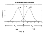
- the maximum likelihood classifier is illustrated in FIG. 3 where normality is assumed for the target and not-target class-conditional probability density functions P(X/C t ) 20 and P(X/C nt ) 24 .
- the univariate Gaussian density functions, 20 and 24 , in FIG. 3 are defined as
- An equivalent decision rule to that in eq. (1), can be obtained by dividing both sides of eq. (1) by the unconditional probability of X, which is P(X), or
- Equation (10) is referred to as the adaptive Bayes decision rule.
- the prior probability, P C t , of the target, in eq. (10), is assumed to be known.
- the function P(C t /X) 32 is a transformation from the d-dimensional measurement space to the one-dimensional line.
- the function P(X/C t ) 32 maps the target samples as close as possible to “1” in region R C t 38 and it maps the not-target samples as close as possible to “0” in region R C nt 40 .
- the Adaptive Bayes decision rule, eq. (10) is adaptive for the following reason. It is capable of adapting the decision boundary to provide optimal discrimination between the “target” class and any unknown “not-target” class that may exist in the data set to be classified.
- the target class-conditional probability density function, P(X/C t ), in the numerator of eq. (11) can be estimated using labeled sample from the “target” class. For example, if P(X/C t ) is normally distributed, its mean and variance can be estimated from training samples.
- the unconditional probability density function, P(X), in the denominator of eq. (11) is not conditioned of a class and can be estimated using unlabeled samples from the data set to be classified.
- P(X) can be estimated using K th Nearest Neighbor [R. O. Duda and P. E. Hart, Pattern Classification and Scene Analysis , New York: John Wiley & Sons, 1973, pp. 87].
- P(X/C t ) and P(X) the target posterior probability function, P(C t /X), eq. (11), can estimated and used to classifying data using the adaptive Bayes decision rule, eq. (10).
- P(X) can be re-estimated using unlabeled data from this new data set and a new target posterior probability function, P(C t /X), derived.
- This new estimator for the posterior probability function P(C t /X) re-optimizes (adapts) the decision boundary to accommodate any changes in the distribution of the “not-target” class in the new data set.
- the target posterior probability function, P(C t /X), eq.(11), can be approximated by minimizing the mean square difference between the estimated target posterior probability function, ⁇ circumflex over (P) ⁇ (C t /X), and the true target posterior probability function, P(C t /X).
- the least square criterion, eq. (12), is reformulated below to provide an equivalent criterion, with no unknowns, which can be minimized to estimate the parameters of a function which approximates the true target posterior probability function, P(C t /X), in a least-squares sense.
- the most important attribute of the least-squares criterion, eq. (33), is that it can be evaluated using only unlabeled samples from the search image and labeled samples from the target.
- a T F(X) is a transformation from the d-dimensional measurement space to the one-dimensional real line.
- the least-square criterion in eq. (33) is minimized if A T F(X) maps the target samples as close to one as possible and the unlabeled samples, as close to zero as possible.
- This invention relates generally to a system and method for correlating two images for the purpose of identifying a target in an image where templates are provided a priori only for the target. Information on the other objects in the image being searched may be unavailable or difficult to obtain.
- the system and method treats the problem of designing target matching-templates and target matched-filters for image correlation as a statistical pattern recognition problem. By minimizing a suitable criterion, a target matching-template or a target matched-filter is estimated which approximates the optimal Bayes discriminant function in a least-squares sense.
- These target matching-templates and target matched-filters when applied to a search image, identifies the target in the search image with minimum probability of error while requiring no a priori knowledge of other unknown objects that may exist in the image being searched.
- Optimal Bayes target matching-templates and target matched-filters are estimated using a set of labeled patterns derived from target templates and unlabeled patterns derived from the image to be searched.
- Bayes target matching-templates and target matched-filters estimation is accomplished by utilizing a statistical estimator capable of extracting statistical information corresponding to the other unknown objects in a search image without recourse to the a priori knowledge normally provided by training samples from the other objects in the scene.
- the system and method is adaptive in the sense that both the Bayes target matching-template and the Bayes target matched-filter can be readily re-optimizing (adapting) to provide optimal discrimination between the target and any unknown objects which may exist in a new search image using only unlabeled measurements from the new search image.
- the operation of the system can be divided into an off-line training procedure and an on-line image correlation procedure.
- the first embodiment of the Adaptive Bayes Image Correlation System uses a spatial template-matching method of image correlation. It uses a set of labeled patterns, derived from target templates, and unlabeled patterns derived from the image to be searched, to estimate an optimal Bayes target matched-template. This Bayes target matching-template, when correlated with the input search image, identifies and locates the target in the search image with minimum error.
- the second embodiment of the Adaptive Bayes Image Correlation System uses a frequency domain matched-filter method for image correlation which is implemented using the Fast Fourier Transform (FFT).
- FFT Fast Fourier Transform
- the second embodiment uses a set of labeled patterns, derived from target templates, and unlabeled patterns derived from the image to be searched, to estimate an optimal Bayesian target matched-filter.
- This matched-filter when correlated with the input search image, identifies and locates the target in the search image with minimum error.
- FIG. 1 block diagram for a basic image correlation procedure
- FIG. 2 correlation search area and target reference image(s)
- FIG. 3 plot illustrating maximum likelihood classification using two class conditional Gaussian probability density functions
- FIG. 4 plot illustrating the unconditional probability density function, P(X), which is the sum of two Gaussian distributions.
- FIG. 5 plot illustrating the Adaptive Bayes Decision Rule using the target conditional posterior probability function
- FIG. 6 block diagram for the Adaptive Bayes Image Correlation System, including its components, for the preferred embodiment.
- FIG. 7 illustration of the correlation search area and a target matching-template
- FIG. 8 processing flow diagram for the off-line training module for the first embodiment of the Adaptive Bayes Image Correlation System
- FIG. 9 processing flow for the on-line Adaptive Bayes Correlation Module for the first embodiment of the Adaptive Bayes Image Correlation System
- FIG. 10 plot of a two-dimension Hanning (cosine) truncation function
- FIG. 11 illustration of the padded search image and the padded Bayes target matching-template
- FIG. 12 processing flow diagram for the off-line training module for the second embodiment of the Adaptive Bayes Image Correlation System
- FIG. 13 processing flow for the on-line Adaptive Bayes Correlation Module for the second embodiment of the Adaptive Bayes Image Correlation System
- FIGS. 14 A- 14 D test object templates and 3-d surface plots of the gray levels for test objects
- FIGS. 15 A- 15 E test results from the first performance test of the Adaptive Bayes Image Correlation System
- FIGS. 16 A- 16 F test results from the second performance test of the Adaptive Bayes Image Correlation System
- FIGS. 17 A- 17 F test results from the third performance test of the Adaptive Bayes Image Correlation System
- the first embodiment of the Adaptive Bayes Image Correlation System uses a template-matching method to correlate images.
- the template-matching method of cross-correlation is normally considered computationally intensive and not suitable for real-time applications. This is true when the search image and the target template are similar in size. However it is important to note that the dimensions of the target template T(y,z) are usually of much smaller than the dimensions of the search image S(y,z).
- Moik Moik, J. G.; Digital Processing of Remotely Sensed Images, NASA SP-431, National Aeronautics and Space Administration, 1980, pp. 66] showed that when the dimensions of the target template are much smaller than the dimensions of the search image, the template-matching method requires fewer computations than frequency domain methods using the Fast Fourier Transform (FFT). For example, a trade-off performed by Moik showed that if the search image is 256 ⁇ 256 pixels in size and the target template is 13 ⁇ 13 pixels (or less) in size, template-matching image correlation is computationally more efficient than FFT's for image correlation.
- FFT Fast Fourier Transform
- the first embodiment of the Adaptive Bayes Image Correlation system 42 is defined to consist of an Adaptive Bayes Image Correlator 52 , a Training Module 44 , a Processing Unit 50 , Memory 46 , a User Interface Device 48 , and an Output Device 54 .
- the Adaptive Bayes Image Correlation system operates to process measurements from an input Search Image into two classes, target and not-target, for purposes of 1) identifying the presences of targets in an input Search Image, 2) estimating the probability of a correct fix, and 3) estimating the location of the target(s) in the Search Image.
- the first embodiment of the Adaptive Bayes Image Correlation system can be used in a number of applications, such as medical image registration, GIS, content-based image retrieval, face recognition, fingerprint recognition, and registration of multi-spectral images acquired from earth-observing satellites.
- Equation (49) computes a nearest neighbor metric for target identification.
- the first embodiment uses a modification of the standard approach, for searching an image for the target.
- Construction of W(y,z) is accomplished by filling in the two-dimensional template, W(y,z), column-wise.
- the first column of W(y,z) is constructed from the first M elements of the A vector.
- the next column is constructed from the next M elements of the A vector, and so forth, for all M columns of W(y,z).
- the size of W(y,z) is M ⁇ M.
- correlation between the Bayes target matching-template, W(y,z) 60 , and the search image is performed by systematically scanning the Bayes target matching-template across the search image S(y,z) 56 .
- a correlation measure, C(y,z) is computed between the Bayes target matching-template, W(y,z), and each sub-area S(y ⁇ u,z ⁇ v) 58 of the search image S(y,z) 56 .
- the center of sub-area S(y ⁇ u,z ⁇ v) 58 is located at (u,v) 59 . Scanning of the search image is accomplished by incrementing (u,v) over all permissible values of y and z.
- the adaptive Bayes spatial template-matching correlator is defined as:
- the outputs from the first embodiment of the Adaptive Bayes Image Correlation system are target locations in the search image and the probabilities of a correct fix at the target locations.
- Step 1 Constructing Labeled Target Measurement Vectors from the Target Templates
- the off-line method 62 for the first embodiment begins with step 64 , where labeled target measurement vectors are created from input two-dimensional target template(s). This is accomplished as follows:
- a target measurement vector X t (j) is constructed from T j (y,z) by stacking the M columns of T j (y,z).
- the first M elements of the target measurement vector X t (j) are the elements of the first column of T j (y,z), the next M elements are from the second column, and so forth, for all M columns of T j (y,z).
- the off-line method 62 continues with step 66 , where unlabeled measurement vectors are created from the search image as follows: As shown in FIG. 2 , the image to be searched, S(y,z) 12 , is considered for simplicity, to be N ⁇ N pixels in size where N>M. We select a M ⁇ M dimension sub-area S(y ⁇ u,z ⁇ v) 14 which is equal to the target template in size. As shown in FIG. 2 , the center of sub-area S(y ⁇ u,z ⁇ v) is located at (u,v) 15 .
- An unlabeled measurement vector, X(i) is constructed from the M ⁇ M sub-area S(y ⁇ u,z ⁇ v) 14 by stacking the columns of the M ⁇ M sub-area.
- the search image is systematically scanned by incrementing u and v, over the permissible arrange of y and z.
- the index i for X(i) is indexed to u and v.
- Step 4 Construct Two-Dimensional Bayes Target Matching-Template, W(y,z)
- the size of W(y,z) is M ⁇ M.
- Step 1 Correlate the Bayes Target Matching-Template and the Search Image
- the on-line method 72 for the first embodiment begins with step 74 where correlation is performed between the Bayes target matching-template, W(y,z), and the search image.
- FIG. 7 shows a depiction of the Bayes target matching-template W(y,z) 60 , and the search image S(y,z) 56 .
- correlation between the Bayes target matching-template, W(y,z) 60 , and the search image sub-area S(y,z) 56 is performed by systematically scanning the Bayes target matching-template across the search image S(y,z) 56 .
- a correlation measure, C(y,z) is computed between the Bayes target matching-template, W(y,z), and each sub-area S(y ⁇ u,z ⁇ v) 58 of the search image S(y,z) 60 using the following expression: If: C ( y,z ) ⁇ 1 ⁇ 2 (56)
- C(y,z) at location (y,z) is an estimate of the probability of a correct fix at location (y,z) in the search image or P ( C t /X ) (y,z) ⁇ C ( y,z ) (57)
- Step 2 Adaptive Bayes Decision Module
- step 76 the results from the correlation process in step 74 are evaluated to identify the presences of the target in the search image using the Bayes decision rule.
- the adaptive Bayes decision criteria for locating a target is: If: C ( y,z ) ⁇ 1 ⁇ 2 (58)
- the outputs from the first embodiment of the Adaptive Bayes Image Correlation procedure are target locations in the search image and probabilities of a correct fix, C(y,z), at the target locations.
- the second embodiment of the Adaptive Bayes Image Correlation System uses a matched-filter approach to image correlation, implemented using the Fast Fourier Transform (FFT).
- FFT Fast Fourier Transform
- Frequency domain image correlation is a computationally efficient technique for image cross-correlation.
- Moik Moik, J. G.; Digital Processing of Remotely Sensed Images, NASA SP-431, National Aeronautics and Space Administration, 1980, pp. 66] showed that when the target template and the search image are similar in size, the number of computations required to perform image cross-correlation using FFT's is almost independent of the size of the images being cross-correlated.
- Another important property of Fourier transforms is that convolution of two functions in the spatial domain is equivalent to multiplication in spatial frequency domain.
- the second embodiment of the Adaptive Bayes Image Correlation system 42 is defined to consist of an Adaptive Bayes Image Correlator 52 , a Training Module 44 , a Processing Unit 50 , Memory 46 , a User Interface Device 48 , and an Output Device 54 .
- the Adaptive Bayes Image Correlation system operates to process measurements from an input Search Image into two classes, target and not-target, for purposes of 1) identifying the presences of targets in an input Search Image, 2) estimating the probability of a correct fix, and 3) estimating the location of the target(s) in the Search Image.
- the second embodiment of the Adaptive Bayes Image Correlation system is particularly well suited for real-time applications such as guiding a missile to a pre-selected target, medical image registration, GIS, and content-based image retrieval, face recognition, fingerprint recognition and registration of multi-spectral images, acquired from earth-observing satellites.
- T(f y ,f z )* is the complex conjugate of T(f y ,f z ).
- the function, T(f y ,f z ), is referred to as the target matched-filter.
- Construction of the W(y,z) is accomplished by filling in the two-dimensional Bayes target matching-template, W(y,z), column-wise.
- the first column of W(y,z) is constructed from the first M elements of the A vector.
- the size of W(y,z) is M ⁇ M.
- a two-dimensional time domain truncation function [Brigham, E. O., The Fast Fourier Transform and Its Applications, Prentice Hall, 1988, pp. 181-182] is applied to the Bayes target matching-template, W(y,z).
- a popular choice for a time domain truncation function is the Hanning (cosine) function.
- a two-dimensional Hanning truncation function, H(y,z) can be generated for a M ⁇ M image using the following expression:
- FIG. 10 shows an example of a two-dimensional Hanning truncation function 78 generated using eq. (63).
- FIG. 11 depicts a truncated Bayes target matching-template W T (y,z) 84 , and a padded Bayes matching-template W T p (y,z) 86 . Also depicted in FIG. 11 is a Search Image, S(y,z) 80 , and a padded search image, S p (y,z) 82 .
- W T p (f y ,f z ) is the Bayes target matched-filter—obtained by taking the FFT of the Bayes target matching-template.
- the target posterior probability function P(C t /X) can be approximated using ⁇ circumflex over (P) ⁇ (C t /X) ⁇ A T X.
- C(y,z) at location (y,z) in the search image is an estimate of the probability of a correct fix at location (y,z), or ⁇ circumflex over (P) ⁇ ( C t /X ) (y,z) ⁇ C ( y,z ) (68)
- the adaptive Bayes decision rule for locating a target in the search image is: If: C ( y,z ) ⁇ 1 ⁇ 2 (69)
- the outputs from the second embodiment of the Adaptive Bayes Image Correlation procedure are target locations in the search image and probabilities of a correct fix at the target locations.
- Step 1 Constructing Labeled Target Measurement Vectors from Target Templates
- the off-line method 88 for the second embodiment begins with step 90 , where labeled target measurement vectors are created from input two-dimensional target template(s) as follows:
- a target measurement vector, X t (j) is constructed from T j (y,z) by stacking the M columns of T j (y,z).
- the first M elements of the target measurement vector X t (j) are the elements of the first column of T j (y,z), the next M elements are from the second column, and so forth, for all M columns of T j (y,z).
- the off-line method 88 for the second embodiment continues with step 92 , where unlabeled measurement vectors are created from the search image as follows:
- the image to be searched, S(y,z) 12 is considered for simplicity, to be N ⁇ N in size where N>M.
- the center of sub-area S(y ⁇ u,z ⁇ v) is located at (u,v) 15 .
- An unlabeled measurement vector, X(i) is constructed from the M ⁇ M sub-area S(y ⁇ u,z ⁇ v) 14 by stacking the columns of the M ⁇ M sub-area.
- the search image is systematically scanned by incrementing u and v over a permissible range of y and z.
- the index i for X(i) is indexed to u and v.
- Step 4 Construct Two-Dimensional Bayes Target Matching-Template, W(y,z)
- the size of W(y,z) is M ⁇ M.
- Step 5 Apply Two-Dimensional Time Domain Truncation Function to Bayes Target Weighting Template
- step 98 a two-dimensional truncation function, such as the Hanning truncation function, is generated and applied to the two-dimensional Bayes target matching-template W(y,z).
- the Hanning truncation function, H(y,z) is generated using the following expression:
- Step 6 Padding the Bayes Target Weighting Template and the Search Image
- the off-line method 88 for the second embodiment continues with step 100 , where the truncated Bayes target matching-template, W T (y,z), and the search image, S(y,z), are padded with zeros to prevent edge effects or circular correlation.
- the outputs from this padding process are W TP (y,z) and S P (y,z).
- Step 7 Apply FFT to the Padded Bayes Target Weighting Template and the Padded Search Image
- the function W TP (f y ,f z ) is the Bayes target matched-filter—obtained by taking the FFT of the Bayes target matching-template in eq. (73).
- Step 1 Correlate the Bayes Target Matched-Filter and the Search Image
- the on-line method 104 for the second embodiment begins with step 106 where correlation is performed between the Bayes target matched-filter and the search image.
- the inputs to this step are the Bayes target matched-filter, W TP (f y ,f z ), and the FFT of the search image, S P (f y ,f z ).
- C(y,z) is an estimate of the probability of a correct fix at location (y,z) in the search image, or P ( C t /X ) (y,z) ⁇ C ( y,z ) (76)
- Step 2 Adaptive Bayes Decision Module
- step 108 the results from the correlation process in step 106 are evaluated to identify the presences of the target in the search image using the Bayes decision rule, or If: C ( y,z ) ⁇ 1 ⁇ 2 (77)
- the outputs from the second embodiment of the Adaptive Bayes Image Correlation procedure are target locations in the search image and the probabilities of a correct fix at those target locations.
- the performance of the two embodiments of the Adaptive Bayes Image Correlation System is illustrated below using three examples.
- the first test example demonstrates the performance of the two embodiments of Adaptive Bayes Image Correlation System (i.e., the spatial matching-template correlator and the frequency domain matched-filter image correlator) in finding the target in a search image which contains only the target.
- the second and third examples demonstrate the ability of the two embodiments of Adaptive Bayes Image Correlation System in locating a target in a search image which contains both the target and an unknown object.
- the first object shown in FIG. 14A , is a grey level image rendition of a two-dimension Gaussian function.
- FIG. 14B shows a three-dimensional surface plots of the grey levels of the Gaussian object.
- the second object shown in FIG. 14C is a grey scale image of a square shaped object.
- FIG. 14D is three-dimensional surface plots of the grey levels of the square object.
- the purpose of the first test case is to demonstrate the performance of the two embodiments of the Adaptive Bayes Image Correlation system in the ideal situation where the search image contains only the target.
- FIG. 15 shows the correlation test results for the first test case.
- FIG. 15A The template for the target being searched for (the Gaussian object) is shown in FIG. 15A .
- the search image is shown in FIG. 15B .
- FIG. 15C shows a three-dimensional surface plot of the grey levels 110 of the search image containing the target (a Gaussian object).
- FIG. 15D shows the correlation results 112 generated using the first embodiment of the Adaptive Bayes Image Correlation system, (the Bayes matching-template image correlator). Comparing the target location 110 in the search image, shown in FIG. 15C , with the target location 112 shown in correlation results in FIG. 15D , it can be seen in FIG. 15D that correlation peaks at the correct target location and the probability of a correct fix, C(y,z), at that location is 0.954 (or 95.4%).
- FIG. 15E shows the correlation results generated using the second embodiment of the Adaptive Bayes Image Correlation system (the frequency domain matched-filter image correlator).
- correlation peak 112 for the first embodiment is much sharper than the correlation peak 114 for the second embodiment and thus the first embodiment provides a more precise target location estimate.
- Second Test Case Search Image Contains Both a Target (a Gaussian Object) and an Unknown Object (a Square Object)
- the purpose of the second test is to demonstrate the performance of the two embodiments of the Adaptive Bayes Correlation System in the locating a target (a Gaussian object) in a search image which also contains an unknown object (a square object).
- test results are presented which demonstrate the results achievable using the standard spatial template matching image correlator, as defined in eq. (49).
- FIG. 16 shows correlation test results for the second test case.
- the target template (a Gaussian object) is shown in FIG. 16A .
- the search image shown in FIG. 16B , contains both a target (a Gaussian object) and an unknown object (a square object).
- Shown in FIG. 16C is a three-dimensional surface plot of the grey levels of the search image containing the target 116 (a Gaussian object) and the unknown object 118 (a square object).
- FIG. 16D shows the correlation results generated using the first embodiment of Adaptive Bayes Image Correlation System (the template matching method). Comparing the target location 116 in the search image, shown in FIG. 16C , with the target location 120 shown in correlation results in FIG. 16D , it can be seen in FIG. 16D that correlation peaks at the correct target location and the probability of a correct fix, C(y,z), at that location is 0.208 (or 20.8%).
- FIG. 16E shows the correlation results generated by the second embodiment of the Adaptive Bayes Image Correlation system (the frequency domain matched-filter method). Comparing the target location 116 in the search image, shown in FIG. 16C , with the target location 122 shown in correlation results in FIG. 16E , it can be seen in FIG. 16E that correlation peaks at the correct target location and the probability of a correct fix, C(y,z), at that location is 0.192 (or 19.2%).
- both embodiments of the Adaptive Bayes Correlation system were successful in locating the target.
- the probabilities of a correct fix at these locations were low—less than 0.5 (or 50%).
- Low confidence indicates that the target and the unknown object were very similar and as a result both embodiments of the Adaptive Bayes Correlation system had difficulty in discriminating between the target (the Gaussian object) and the unknown object (the Square object).
- a procedure for improving the confidence of these location fixes is described below.
- the first embodiment of Adaptive Bayes Image Correlation System provides the sharpest peak 120 and therefore the most precise estimate target location.
- the sidelobes for the first embodiment are much higher than those of the second embodiment of Adaptive Bayes Image Correlation System.
- the second embodiment of Adaptive Bayes Image Correlation System had little or no sidelobes and therefore its peak-to-sidelobe ratio is expected to be very high.
- FIG. 16F shows test results for the standard spatial template matching image correlator, as defined in eq. (49).
- the target 124 the Gaussian object
- the unknown object 126 the Square Object
- the standard correlator correctly identified the target, since the target has the higher correlation peak.
- the correlation peaks are very similar in amplitude which implies a low confidence target location fix.
- the amplitude of the correlation peaks is not a predictor of the probability of a correct fix.
- the purpose of the third test is to demonstrate the performance of the two embodiments of the Adaptive Bayes Correlation System in the locating the target (a Square object) in a search image which also contains an unknown object (a Gaussian object).
- the third test case is the reverse of the second test case, where the target object and the unknown object are switched.
- results are presented which demonstrate the results achievable using the standard spatial template matching image correlator, defined in eq. (49).
- FIG. 17 shows correlation test results for the third test case.
- the target template (a Gaussian object) is shown in FIG. 17A .
- the search image shown in FIG. 17B , contains both a target (the Square object) and an unknown object (the Gaussian object).
- Shown in FIG. 17C is a three-dimensional surface plot of the grey levels of the search image containing the target 128 (a square object) and the unknown object 130 (a Gaussian object).
- FIG. 17D shows the correlation results generated using the first embodiment of Adaptive Bayes Image Correlation System (the spatial template matching method of image correlation). Comparing the target location 128 in the Search Image in FIG. 17C , with the first embodiment correlation results 132 in FIG. 17D , it can be seen that correlation peaks at the target location and the probability of a correct fix , C(y,z), at that location is 0.448 (or 44.8%).
- FIG. 17E shows the correlation results generated by the second embodiment of the Adaptive Bayes Image Correlation System (the frequency domain matched-filter method of image correlation). Comparing the target location 128 in the Search Image in FIG. 17C , with the correlation results 134 from the second embodiment in FIG. 17E , it can be seen that correlation peaks at the target location and the probability of a correct fix, C(y,z), at that location is 0.117 (or 11.7%).
- both adaptive Bayes image correlators were successful in locating the target.
- the probabilities of a correct fix at these locations were low, less than 0.5 (or 50%).
- Low confidence indicates that the target and the unknown object were very similar and as a result both embodiments of the Adaptive Bayes Correlation system had difficulty in discriminating between the target (the Square object) and the unknown object (the Gaussian object).
- a procedure for improving the confidence of these location fixes is described below.
- FIG. 17F shows test results for the standard spatial template matching image correlator, as defined in eq. (49).
- the target 136 the Square object
- the unknown object 138 the Gaussian Object
- the standard correlator correctly identified the target, since the target has the higher correlation peak.
- the correlation peaks are very similar in amplitude which implies low confidence the target location fix.
- the amplitude of the correlation peaks is not a predictor of the probability of a correct fix.
- the second and third test cases shown in FIG. 16 and FIG. 17 , provided two examples of accurate target location fixes but with low probabilities of a correct fix.
- the probability of a correct fix C(y,z)
- C(y,z) should be greater than 0.5, or C(y,z) ⁇ 1 ⁇ 2.
- the approach then for improving the confidence in target identification is to extract the pixels surrounding a potential target location (identified by a sharp correlation peak but with a low probabilities of a correct fix) and construct a new search image containing only those extracted pixels.
- a second target search is then performed on the new search image containing only those pixels with appropriate padding. If the object in the new search image is truly the target, the probability of a correct fix should be greater than 0.5, i.e., C(y,z) ⁇ 1 ⁇ 2.
- Test Case Two shown in FIG. 16D and FIG. 16E , it was seen the potential target location had sharply defined correlation peaks, 120 and 122 , but low probabilities of a correct fix, C(y,z) ⁇ 1 ⁇ 2.
- the First Test Case demonstrated that if the search image truly contains only the target, the probability of a correct fix, C(y,z), will be close to 1.0. This can be seen by examining by the heights of the correlation peaks 112 and 114 in FIG. 15D and FIG. 15E , were both are close to 1.0. If the new search image does not contain the target, the probability of a correct fix, C(y,z) will be less than 0.5, or C(y,z) ⁇ 1 ⁇ 2.
- the Adaptive Bayes Image Correlation system can be used in many real world applications for correlating two images for the purpose of identifying a target in an image where templates are provided a priori only for the target. Information on the other objects in the image being searched may be unavailable or difficult to obtain.
- This invention treats the problem of designing target matching-templates and target matched-filters for image correlation as a statistical pattern recognition problem. By minimizing a suitable criterion, a target matching-template or a target matched-filter is estimated which approximates the optimal Bayes discriminant function in a least-squares sense.
- both the optimal Bayesian target matching-template and the optimal Bayesian target matched-filter are capable of identifying the target in a search image with minimum probability of error while requiring no a priori knowledge of other unknown objects that may exist in the image being searched.
- Image correlation is used in a number of military applications, such as guiding a missile to pre-selected targets, in medical image registration, robotics, automated manufacturing, GIS, and content-based image retrieval. Registration of multi-spectral images, acquired from earth-observing satellites, is another important application.
- one or more templates are available for targets to be identified in an image (pictures of high valued military targets, pictures of persons on a watch-list).
- the Adaptive Bayes Image Correlation system is capable searching an input image to identify and locate the target in the search image with minimum probability of error and without any a priori knowledge of other unknown object in the image being searched.
- the first embodiment of the Adaptive Bayes Image Correlation System uses a spatial matching-template method of image correlation.
- the first embodiment uses a set of templates, descriptive of the target, and unlabeled patterns, derived from the image to be searched, to estimate an optimal Bayesian target matching-template.
- This Bayesian matching-template when scanned across to the input search image, identifies and locates the target in the search image with minimum error, without any a priori knowledge of other unknown object in the image being searched
- the second embodiment of the Adaptive Bayes Image Correlation System uses a frequency domain matched-filter approach to image correlation, implemented using the Fast Fourier Transform (FFT).
- FFT Fast Fourier Transform
- the second embodiment uses a set of templates, descriptive of the target, and unlabeled patterns derived from the image to be searched, to estimate an optimal Bayes target matched-filter.
- This matched-filter when applied to the input search image, identifies and locates the target in the search image with minimum error, without any a priori knowledge of other unknown object in the image being searched
Abstract
This invention relates generally to a system and method for correlating two images for the purpose of identifying a target in an image where templates are provided a priori only for the target. Information on other objects in the image being searched may be unavailable or difficult to obtain. This invention treats the design of target matching-templates and target matched-filters for image correlation as a statistical pattern recognition problem. By minimizing a suitable criterion, a target matching-template or a target matched-filter is estimated which approximates the optimal Bayes discriminant function in a least-squares sense. Both Bayesian image correlation methods identify the target with minimum probability of error while requiring no prior knowledge of other objects in the image being searched. The system and method is adaptive in that it can be re-optimizing (adapted) to recognize the target in a new search image using only information from the new image.
Description
This application is related to application Ser. No. 12/004,329 filed on Dec. 20, 2007, entitled “Adaptive Bayes Pattern Recognition”, application Ser. No. 12/011,518 filed on Jan. 28, 2008, entitled “Adaptive Bayes Feature Extraction”, and application Ser. No. 12/074,901 filed Mar. 6, 2008, entitled “A Priori Probability and Probability of Error Estimation for Adaptive Bayes Pattern recognition”.
Not Applicable
1. Field of Invention
This invention relates generally to a system and method for correlating two images for the purpose of identifying a target in an image where templates are provided a priori only for the target. Information on the other objects in the image being searched may be unavailable or difficult to obtain. This invention treats the problem of designing target matching-templates and target matched-filters for image correlation as a statistical pattern recognition problem. By minimizing a suitable criterion, a target matching-template or a target matched-filter is estimated which approximates the optimal Bayes discriminant function in a least-squares sense. When applied to an image, both Bayesian image correlation methods are capable of identifying the target in a search image with minimum probability of error while requiring no a priori knowledge of other objects that may exist in the image being searched. The system and method is adaptive in the sense that it can be readily re-optimizing (adapting) to provide optimal discrimination between the target and any unknown objects which may exist in a new search image, using only information from the new image being searched.
2. Prior Art—FIGS. 1 , 2, 3, 4, and 5
Image correlation is the process of comparing a sensor image and a reference image in order to identify the presences and location of the reference image in the sensor image. Accurate identification of the presences of a reference image in another image and accurate and unambiguous measurement of its location is important in many practical applications.
Image correlation is used in a number of military applications, such as guiding a missile to a pre-selected target. It is also used in medical image registration, robotics, automated manufacturing, GIS, Home Land Security/Law Enforcement (fingerprint recognition, face recognition, iris recognition), and content-based image retrieval. Registration of multi-spectral images, acquired from earth-observing satellites, is another important application.
The basic elements of image correlation are shown in FIG. 1 . Referencing FIG. 1 , it can be seen that the inputs to the Correlator 10 are the Search Image and a Target Reference Image. The outputs from the Correlator 10 are the Target Locations in the Search Image and an estimate of the Probability of a Correct Fix.
A number of techniques for image correlation have been reported in the literature, the simplest technique being various forms of the spatial template-matching algorithm [R. O. Duda and P. E. Hart, Pattern Classification and Scene Analysis, New York: John Wiley & Sons, 1973, pp.278], [Ormsby, C. C.; “Advanced scene Matching Techniques,” Proc. IEEE Nat'l Aerospace and Electronic Conf., Dayton, Ohio pp. 68-76, May 15-17, 1979], and [Pratt, W. K,; Digital Image Processing, John Wiley, 1978, pp. 552].
The analog of the spatial template-matching algorithm in the spatial frequency domain is the matched-filter algorithm [R. O. Duda and P. E. Hart, Pattern Classification and Scene Analysis, New York: John Wiley & Sons, 1973, p.307] and [Pratt, W. K,; Digital Image Processing, John Wiley, 1978, pp. 553-560]. Frequency domain matched-filter has the desirable characteristic in that it can be implemented using the fast Fourier transform (FFT) algorithm.
A number of more sophisticated correlation techniques based on matched-filtering have been developed in recent years. These include the phase correlation method [Chen, Q.; Defrise, M.; and Deconinck, F.: “Symmetric Phase-Only Matched Filtering of Fourier-Mellin Transforms for Image Registration and Recognition,” IEEE Trans. on Pattern Analysis and Machine Intelligence, vol. 16, no. 12, Dec. 1994], [Pearson, J. J.; Hines, D. c., Jr.; Golosman, S.; and Kuglin, C. D.: “Video-Rate Image Correlation Processor,” SPIE, vol. 119, Application of Digital Image Processing, pp. 197-205, IOCC 1977], modeling images using feature vectors [Chen, X.; Cham, T.: “Discriminative Distance Measures for Image Matching”, Proceedings of the International Conference on Pattern Recognition (ICPR), Cambridge, England, vol. 3, 691-695, 2004], and optimum filters [Steding, T. L.; and Smith, F. W.: “Optimum Filters for Image registration.” IEEE Trans. on Aerospace and Electronic Systems, vol. ASE-15, no. 6, pp. 849-860, November 1979].
Belsher, Williams, and Kin [Belsher, J. F.; Williams, H. F.; Kin, R. H.: “Scene Matching With Feature Detection,” SPIE, vol. 186, Digital Process of Aerial Images, 1979] were able to treat template-matching as a classical pattern recognition problem by assuming independence between adjacent picture elements (pixels) in the image and by assuming the form of the probability density function to be Gaussian, Laplacian, or Cauchy. Minter [Minter, T. C., “Minimum Bayes risk image correlation”, SPIE, vol. 238, Image Processing for Missile Guidance, pp. 200-208, 1980] was also able to treat matched-filtering as a classical pattern recognition problem by assuming independence between adjacent picture elements (pixels) in the image but without assuming a form for the probability density function. However, the assumption of independence between pixels elements in the image reduces the effectiveness of these image correlation approaches since pixel element correlation is a potentially important source of information in target recognition.
The performance of image correlation techniques is usually characterized in terms of the probability of a false fix on the target (or alternatively, the probability of a correct fix on the target) and registration accuracy. The probability of a correct fix on the target refers to the probability that the correlation peak truly identifies a target in the search image. A related quantity is the peak-to-side-lobe ratio (PSR), which is defined as the value of the match-point correlation peak divided by the root mean square (RMS) value of the correlation function at points excluding this peak. Once the correct peak has been identified, the accuracy with which the true position of the peak is located can be quantified by the variance of the correlation peak location. Webber and Deloshmit [Webber, R. F.; and Deloshmit, W. H.: “Product Correlation Performance for Gaussian Random Scenes,” IEEE Trans. on Aerospace and Electronics Systems, vol. AES-10, no. 4, pp. 516-520, July 1974] have shown that the probability of a false fix is a monotonically decreasing function of the PSR.
This invention treats the problem of designing target matching-templates and target matched-filters for image correlation as a statistical pattern recognition problem. It is shown that by minimizing a suitable criterion, a target matching-template or a target matched-filter can be estimated which approximates the optimum Bayes discriminant function in a least-squares sense. It is well known that the use of the Bayes discriminant function in target classification minimizes the probability of a false fix [R. O. Duda and P. E. Hart, Pattern Classification and Scene Analysis, New York: John Wiley & Sons, 1973, pp.11].
However, the use of pattern recognition techniques in image correlation application presents several unique problems. The target's characteristics are usually well known and an appropriate reference image (or images) is available which provides an appropriate statistical representation of the target. However, often little prior information is available on the statistical characteristics of the other objects (or classes) present in the image which might be confused with the target. This lack of information about the confusion objects (or classes) presents a serious problem in designing an optimal discriminant procedure for recognizing the target.
Most of the literature on Bayes discriminant procedures is restricted to the two-class problem where class-conditional probability distributions functions are either available for each class (or object) or can be estimated from labeled training samples available for each class. Below, the Bayes decision rule is reformulated to make it suitable for use in the unique environment associated with target discriminant. The reformulated decision rule only requires an estimate of the target's posterior probability function. It will be shown that the target's posterior probability function can be estimated using labeled training samples from the target and unlabeled samples from the image being searched. Its application to Bayes image correlation will be discussed.
It will also be shown that the proposed image correlator is adaptive in the sense that it is capable of adapting both the target matching-template and the target matched-filter to provide optimal discrimination between the target and any unknown objects which may exist in the image being searched. If a new search image, with a possibly different set of unknown objects is to be searched, the target matching-template and the target matched-filter can be readily re-optimized (adapted), for the new set of unknown objects before searching the new image. Adaptation is accomplished using only unlabeled patterns from the new image being searched.
Creating Vector Representations of Target Templates and the Search Image
In target discrimination, it is assumed that two classes of objects are in the search image—target and not-target objects. Let Ct be the class (or object) label for target and Cnt be the class (or object) label for not-target. The problem of classification arises when an event described by a set of measurements is to be associated with these two classes. The event cannot be identified directly with a class, so a decision must be made on the basis of the set of observed measurements as to which class the event belongs (i.e., target or not-target). The set of measurements can be represented as a vector in the measurement space. This measurement will be called the measurement vector, or simply a sample, and will be denoted as X=(x1,x2, . . . , xd)T, where the T denotes the transpose and d is the number of measurements or the dimensionality of the measurement space.
In the context of target identification in images:
Let
S(y,z)—be the image to be searched
Tj(y,z)—be a target template
D—be the domain of definition of the target template
(D, for example, might be 20×20 pixels square, whereas the search image might be 500×500 pixels square.)
Labeled measurement vectors for the target can be formed in the following manner: As shown in FIG. 2 , target reference images T1(y,z) 16 thru TK t (y,z) 18, contain examples of the target, which are M×M pixels in size. It is assumed, for the sake of generality, that Kt reference images, Tj(y,z), j=1, 2, . . . , Kt, are available, each containing an example of the target. A target measurement vector Xt(j) is constructed from Tj(y,z) by stacking the M columns of Tj(y,z). The first M elements of the target measurement vector Xt(j) are the elements of the first column of Tj(y,z), the next M elements of Xt(j) are from the second column of Tj(y,z), and so forth, for all M columns of Tj(y,z). The dimension, d, of Xt(j) is d=M2. This procedure produces Kt measurement vectors, Xt(j), j=1, 2, . . . , Kt, one for each target template.
Unlabeled measurement vectors from the search image S(y,z) can be formed in a similar manner. Again, referencing FIG. 2 , the image to be searched, S(y,z) 12, is considered for simplicity, to be N×N in size where N>M. We select a M×M dimension sub-area S(y−u,z−v) 14 which is equal to the target template in size. As shown in FIG. 2 , the center of sub-area S(y−u,z−v) is located at (u,v) 15. An unlabeled measurement vector, X(i), is constructed from the M×M sub-area S(y−u,z−v) 14 by stacking the columns of the M×M sub-area. The dimensional, d, of the unlabeled measurement vector, X(i), is d=M2. The search image is systematically scanned by incrementing u and v. The index i for X(i) is indexed to u and v. From the search image, K unlabeled measurement vectors, X(i), i=1, 2, . . . , K are constructed where K=(N−M+1)2.
The Adaptive Bayes Approach to Pattern Recognition
Bayes decision theory is a fundamental approach to the problem of pattern recognition [R. O. Duda and P. E. Hart, Pattern Classification and Scene Analysis, New York: John Wiley & Sons, 1973, pp. 11-17]. The approach is based on the assumption that the decision problem can be poised in probabilistic terms where all of the relevant probability values are known. Specifically, the application of a standard Bayes classifier requires estimation of the posterior probabilities of each class. If information about the probability distributions of classes is available, the posterior probability can be calculated for each measurement and each measurement can be attributed to the class with the highest posterior probability.
However, this traditional approach is not feasible when unknown “not-target” classes are present in the search image. Traditional approaches require that the number of “not-target” classes be known in advance and a training set (or class distributions) be available for all classes in the image to be classified to ensure optimal classifier performance. A modification to the standard Bayes decision rule is presented below to address this problem.
The decision making process for Bayes pattern recognition can be summarized as follows: Given a set of K measurement vectors, X(i), i=1, 2, . . . , K, it is desired to associate the measurements with either the “target” or the “not-target” class with minimum probability of error where X is a d-dimensional vector in the measurement space or X=(x1,x2, . . . , xd)T.
For the moment, let us assume that complete information, in the form of labeled training samples, is available for the “target” and the “not-target” classes. Using training samples from these two classes, we can estimate conditional probability density functions for the two classes where P(X/Ct) is the conditional probability density function (pdf) for the “target”, and P(X/Cnt) is the pdf for the “not-target” class. We will assume that the associated prior probabilities for the two classes, PC t and PC nt , are known. Using these probability estimates, the standard maximum likelihood decision rule for two class pattern recognition is:
If: P Ct P(X/C t)≧P C nt P(X/C nt), (1)
If: P C
-
- Classify X as target
- Otherwise, Classify X as not-target
where - P(X/Ct)=Conditional probability density function of the “target” class
- P(X/Cnt)=Conditional probability density function of the “not-target” class
- PC
t =prior probability of the “target” - PC
nt =prior probability of the “not-target” class
The maximum likelihood classifier is illustrated in FIG. 3 where normality is assumed for the target and not-target class-conditional probability density functions P(X/Ct) 20 and P(X/Cnt) 24. The decision boundary 22, where PC t P(X/Ct)=PC nt P(X/Cnt), is also shown.
The univariate Gaussian density functions, 20 and 24, in FIG. 3 are defined as
The parameters of the density functions in FIG. 3 are μC t =7, μC nt =13, σC t =3, and σC nt =3. The prior probabilities are PC t =0.5 and PC nt =0.5.
Again referencing FIG. 3 it can be seen that
-
- RC
t =region where samples are classified as “target” 26: i.e., where P(X/Ct)≧P(X/Cnt) - RC
nt =region where samples are classified as “not-target” 28: i.e., where P(X/Ct)<P(X/Cnt)
- RC
An equivalent decision rule, to that in eq. (1), can be obtained by dividing both sides of eq. (1) by the unconditional probability of X, which is P(X), or
-
- Classify X as target
- Otherwise, Classify X as not-target
where
P(X)=P Ct P(X/C t)+P Cnt P(X/C nt) (4)
A graph of P(X) 30, eq. (4) is shown inFIG. 4 .
The Bayes decision rule can be defined in terms of posterior probabilities as:
If: P(C t /X)≧P(C nt /X); (5) - Classify X as target,
- Otherwise, classify X as not-target
where P(Ct/X) and P(Cnt/X) are the conditional posterior probability functions for the “target” and the “not-target” classes respectively. These posterior probability functions are defined as:
Minter [T. C. Minter, “A Discriminant Procedure for Target Recognition in Imagery Data”, Proceedings of the IEEE 1980 National Aerospace and Electronic Conference—NAECON 1980, May 20-22, 1980] proposed an alternative Bayes decision rule that can be derived by noting that the two posterior probability functions sum to 1, namely
P(C t /X)+P(C nt /X)=1 (8)
Rearranging eq. (8) we get
P(C nt /X)=1−P(C t /X)
(9)
P(C t /X)+P(C nt /X)=1 (8)
Rearranging eq. (8) we get
P(C nt /X)=1−P(C t /X)
(9)
Substituting eq. (9) into (5) and simplifying, we obtain an alternative Bayes decision rule which only involves the target posterior distribution function, namely
If: P(C t /X)≧½, (10)
If: P(C t /X)≧½, (10)
-
- Classify X as the target
- Otherwise, Classify X as not-target
where
Equation (10) is referred to as the adaptive Bayes decision rule. The prior probability, PC t , of the target, in eq. (10), is assumed to be known.
-
- RC
t =region where samples are classified as “target” 38: i.e., where P(Ct/X)≧½ - RC
nt =region where samples are classified as “not-target” 40: i.e., P(Ct/X)<½
- RC
Again referencing FIG. 5 , a useful observation is that the function P(Ct/X) 32 is a transformation from the d-dimensional measurement space to the one-dimensional line. The function P(X/Ct) 32 maps the target samples as close as possible to “1” in region R C t 38 and it maps the not-target samples as close as possible to “0” in region R C nt 40.
The Adaptive Bayes decision rule, eq. (10), is adaptive for the following reason. It is capable of adapting the decision boundary to provide optimal discrimination between the “target” class and any unknown “not-target” class that may exist in the data set to be classified. In particular, the target class-conditional probability density function, P(X/Ct), in the numerator of eq. (11), can be estimated using labeled sample from the “target” class. For example, if P(X/Ct) is normally distributed, its mean and variance can be estimated from training samples. The unconditional probability density function, P(X), in the denominator of eq. (11), is not conditioned of a class and can be estimated using unlabeled samples from the data set to be classified. A number of nonparametric density function estimation techniques are available for estimating P(X). For example P(X) can be estimated using Kth Nearest Neighbor [R. O. Duda and P. E. Hart, Pattern Classification and Scene Analysis, New York: John Wiley & Sons, 1973, pp. 87]. Using estimates for P(X/Ct) and P(X), the target posterior probability function, P(Ct/X), eq. (11), can estimated and used to classifying data using the adaptive Bayes decision rule, eq. (10). If a new data set is to be classified, P(X), can be re-estimated using unlabeled data from this new data set and a new target posterior probability function, P(Ct/X), derived. This new estimator for the posterior probability function P(Ct/X), re-optimizes (adapts) the decision boundary to accommodate any changes in the distribution of the “not-target” class in the new data set.
Gorte [B. Gorte and N. Gorte-Kroupnova, “Non-parametric classification algorithm with an unknown class”, Proceedings of the International Symposium on Computer Vision, 1995, pp. 443-448], Mantero [P. Mantero, “Partially supervised classification of remote sensing images using SVM-based probability density estimation”, IEEE Transactions on Geoscience and Remote Sensing, vol. 43, no. 3, March 2005, pp. 559-570], and Guerrero-Curieses [A. Guerrero-Curieses, A Biasiotto, S. B. Serpico, and. G. Moser, “Supervised Classification of Remote Sensing Images with Unknown Classes,” Proceedings of IGARSS-2002 Conference, Toronto, Canada, June 2002] investigated using Kth Nearest Neighbor probability estimation techniques to estimate P(Ct/X), eq. (11), and classify data using the adaptive Bayes decision rule, eq. (10). They demonstrated that it can be used successfully in crop identification using remotely sensed multi-spectral satellite imagery.
Minter [T. C. Minter, “A Discriminant Procedure for Target Recognition in Imagery Data”, Proceedings of the IEEE 1980 National Aerospace and Electronic Conference—NAECON 1980, May 20-22, 1980] proposed an alternative least squares criterion for approximating the target posterior probability, P(Ct/X). This least squares algorithm uses labeled samples from the target-class and unlabeled samples from the image to be classified, to approximate the target posterior probability function, P(Ct/X), with a function. This least squares criterion is described below.
Least Squares Estimation of the Adaptive Bayes Decision Function
The target posterior probability function, P(Ct/X), eq.(11), can be approximated by minimizing the mean square difference between the estimated target posterior probability function, {circumflex over (P)}(Ct/X), and the true target posterior probability function, P(Ct/X). The least squares criterion is:
J=∫ {circumflex over (P)}(C t /X)−P(C t /X)
 2 P(X)dX+C (12)
where
J=∫
where
and, C, in eq. (12), is an arbitrary constant.
The least squares criteria, eq. (12), cannot be minimized directly since the true target posterior probability function, P(Ct/X), is unknown.
The least square criterion, eq. (12), is reformulated below to provide an equivalent criterion, with no unknowns, which can be minimized to estimate the parameters of a function which approximates the true target posterior probability function, P(Ct/X), in a least-squares sense.
First, expanding the least squares criteria, eq. (12), we get
J=∫({circumflex over (P)}(C t /X)2−2{circumflex over (P)}(C t /X)P(C t /X)+P(C t /X)2)P(X)dX+C (15)
Rearranging we get:
J=∫({circumflex over (P)}(C t /X)2 P(X)dX−∫2{circumflex over (P)}(C t /X)P(C t /X)P(X)dX+∫P(C t /X)2 P(X)dX+C (16)
Substituting in the definition of P(Ct/X), from eq. (11), into the second term of eq. (16), we get:
Noting that P(X) can be canceled out in the second term of eq. (17), we get
J=∫({circumflex over (P)}(C t /X)2 P(X)dX−∫2{circumflex over (P)}(C t /X)P C
Let us choose C in eq. (18) as:
C=2P C
or, multiplying eq. (19) by 1, we get
C=2P C
and noting that
∫P(X/C t)dX=1 (20)
We can substitute eq. (20) into eq. (19) and rewrite eq. (19) as
C=2P C
Substituting this definition of C into eq. (18) we get:
J=∫({circumflex over (P)}(C t /X)2 P(X)dX−2P C
Combining terms and rearranging we get:
J=∫({circumflex over (P)}(C t /X)2 P(X)dX−2P C
Since the third term in eq. (23) is not a function of the estimated target posterior distribution, {circumflex over (P)}(Ct/X), it can be considered a constant. Let us define a new constant C′
C′=∫P(C t /X)2 P(X)dX (24)
Substituting C′ into eq. (23) we get
J=∫({circumflex over (P)}(C t /X)2 P(X)dX−2P C
The expected value of a function (∘) with respect to the labeled samples from the target class is defined as:
E Ct (∘)=∫(∘)P(X/C t)dX (26)
E C
The expected value with respect to the unlabeled samples from P(X) (the data to be classified) is defined as:
E(∘)=∫(∘)P(X)dX (27)
E(∘)=∫(∘)P(X)dX (27)
Using these definitions, the least square criteria, eq. (25), can be rewritten as:
J=E[{circumflex over (P)}(C t /X)2]+2P Ct E C t [{circumflex over (P)}(C t /X)−1]+C′ (28)
We will approximate the posterior probability of the class-of-interest {circumflex over (P)}(Ct/X) using a linear combination of “scalar functions of the measurements”, or
{circumflex over (P)}(C t /X)≅A T F(X) (29)
where F(X) is a vector containing “scalar functions of the measurements”, or
F(X)=(f(X)1 , f(X)2 , . . . f(X)d)T (30)
and the vector A is a vector of weights for the scalar functions, f(X), or
A=(a 1 ,a 2 , . . . a d)T (31)
J=E[{circumflex over (P)}(C t /X)2]+2P C
We will approximate the posterior probability of the class-of-interest {circumflex over (P)}(Ct/X) using a linear combination of “scalar functions of the measurements”, or
{circumflex over (P)}(C t /X)≅A T F(X) (29)
where F(X) is a vector containing “scalar functions of the measurements”, or
F(X)=(f(X)1 , f(X)2 , . . . f(X)d)T (30)
and the vector A is a vector of weights for the scalar functions, f(X), or
A=(a 1 ,a 2 , . . . a d)T (31)
Since the parameter weighting vector, A=(a1,a2, . . . ad)T, is used to approximate the target posterior distribution function {circumflex over (P)}(Ct/X), we will often refer to A=(a1,a2, . . . ad)T as the Bayes parameter weighting vector.
Now, substituting ATF(X), from eq. (28), for {circumflex over (P)}(C t/X) in eq. (28) we get:
J=E[(A T F(X))2]+2P Ct E C t [A T F(X)−1]+C (32)
J=E[(A T F(X))2]+2P C
For a finite set of K unlabeled training samples, X(i), i=1, 2, . . . , K, from the search image and Kt labeled samples, Xt(j), j=1, 2, . . . , Kt, from the target, we can rewrite eq. (32), as
This formulation of the least square error criteria, eq. (33), is equivalent to the original least squares criterion, eq. (12), however eq. (33) is a preferable form since it contains no unknowns and differs only by a constant from eq. (12). In addition, it is shown below that eq. (33) can be minimized to obtain an estimator of the Bayes parameter weighting vector, A=(a1,a2, . . . ad)T.
However, the most important attribute of the least-squares criterion, eq. (33), is that it can be evaluated using only unlabeled samples from the search image and labeled samples from the target.
Another useful observation is that the function ATF(X) is a transformation from the d-dimensional measurement space to the one-dimensional real line. The least-square criterion in eq. (33) is minimized if ATF(X) maps the target samples as close to one as possible and the unlabeled samples, as close to zero as possible.
Estimating the Bayes Parameter Weighting Vector
In this section, an estimator for the Bayes parameter weighting vector A=(a1,a2, . . . ad)T, is obtained by minimization of the least-square criterion, eq. (32).
Differentiating J, in eq. (32), with-respect-to the Bayes parameter weighting vector, A, and setting to zero we get:
Rearranging eq. (34) yields
E[(F(X)F(X)T)]A=P C
and solving for A we get
A=P C
Given a set of K unlabeled samples X(i), i=1, 2, . . . , K from the search image and Kt labeled samples Xt(i), i=1, 2, . . . , Kt from the target, the Bayes parameter weighting vector A=(a1,a2, . . . ad)T may be estimated as follows:
Approximating the Target Posterior Probability Function
Below, a method is presented for approximating the target posterior probability function, {circumflex over (P)}(Ct/X) using a linear combination of scalar functions of the measurements.
For template-matching and matched-filtering, a particularly useful form for the “scalar functions of the measurements” F(X) in eq. (30), is simply the measurement vector X=(x1,x2, . . . , xd)T or
F(X)=(x 1 ,x 2 , . . . , x d)T (38)
Since
{circumflex over (P)}(C t /X)=A T F(X) (39)
the target posterior probability, {circumflex over (P)}(Ct/X), can be approximated using a linear combination of weighted scalar functions of the measurements of the form
{circumflex over (P)}(C t /X)≅a 1 x 1 +a 2 x 2 + . . . +a d x d (40)
where
A=(a 1 ,a 2 , . . . a d)T (41)
and
F(X)=(x 1 ,x 2 , . . . , x d)T (42)
and since X=(x1,x2, . . . , xd)T, then
F(X)=X (43)
Substituting this definition of F(X) into eq. (37) we obtain the following estimator for the Bayes parameter weighting vector A=(a1,a2, . . . ad)T, or
Substituting eq. (43) into eq. (39) we get
{circumflex over (P)}(C t /X)≅A T X (45)
The Adaptive Bayes decision rule for classifying the measurement vector X becomes
If: A T X≧½; (46)
-
- Classify X as target,
- Otherwise, classify X as not-target
Interpreting the Adaptive Bayes Parameter Weighting Vector Estimator
It is important to note that the second term of the estimator for the Bayes parameter weighting vector, A=(a1,a2, . . . ad)T, eq. (37), is simply the mean, μt, of the target measurement vectors, i.e.
Therefore we can re-write eq. (37) as
Equation (47) implies that the target mean, μt, can be estimated from a single target template. In many target recognition application, often only a single target template is available for using in training the classifier. If that single target template is truly representative of the mean of the target, a valid approximation of the target posterior probability function {circumflex over (P)}(Ct/X) can be obtained using the Bayes parameter weighting vector, A=(a1,a2, . . . ad)T, and target posterior probability function {circumflex over (P)}(Ct/X), estimated using eq. (45). This, in turn, implies we can obtain optimal discrimination between the target and not-target objects in the search image using a single target template. Other statistical decision rules, such as the Gaussian maximum likelihood decision rule and the Fisher's linear discriminant, require sufficient numbers of target templates to estimate both the mean and covariance matrix of the target—a significant limitation in target recognition applications.
Again referring to eq. (48), it is also important to note that the M×M matrix,
is formed using unlabeled samples from the image being searched. If a new image is to be searched, a new set of set of unlabeled samples can be obtained from the new search image and used to obtain a new estimate of the M×M matrix,
An updated estimate of the Bayes parameter weighting vector A=(a1,a2, . . . ad)T can then be obtained using eq. (48) and a new approximation of the target posterior probability function {circumflex over (P)}(Ct/X) obtained using eq. (45). Using this updated estimate of {circumflex over (P)}(Ct/X), we can obtain optimal discrimination between the target and not-target objects in the new search image. Thus the decision boundary is re-optimized (adapted) for discriminating between the target and unknown objects in the new search image using only unlabeled samples from the new search image.
This invention relates generally to a system and method for correlating two images for the purpose of identifying a target in an image where templates are provided a priori only for the target. Information on the other objects in the image being searched may be unavailable or difficult to obtain. The system and method treats the problem of designing target matching-templates and target matched-filters for image correlation as a statistical pattern recognition problem. By minimizing a suitable criterion, a target matching-template or a target matched-filter is estimated which approximates the optimal Bayes discriminant function in a least-squares sense. These target matching-templates and target matched-filters, when applied to a search image, identifies the target in the search image with minimum probability of error while requiring no a priori knowledge of other unknown objects that may exist in the image being searched.
Optimal Bayes target matching-templates and target matched-filters are estimated using a set of labeled patterns derived from target templates and unlabeled patterns derived from the image to be searched. Bayes target matching-templates and target matched-filters estimation is accomplished by utilizing a statistical estimator capable of extracting statistical information corresponding to the other unknown objects in a search image without recourse to the a priori knowledge normally provided by training samples from the other objects in the scene. These Bayes target matching-templates and target matched-filters, when applied to an input search image, identify and locate the target in the search image with minimum error.
The system and method is adaptive in the sense that both the Bayes target matching-template and the Bayes target matched-filter can be readily re-optimizing (adapting) to provide optimal discrimination between the target and any unknown objects which may exist in a new search image using only unlabeled measurements from the new search image.
The operation of the system can be divided into an off-line training procedure and an on-line image correlation procedure.
Two embodiments of the Adaptive Bayes Image Correlation System are presented.
The first embodiment of the Adaptive Bayes Image Correlation System uses a spatial template-matching method of image correlation. It uses a set of labeled patterns, derived from target templates, and unlabeled patterns derived from the image to be searched, to estimate an optimal Bayes target matched-template. This Bayes target matching-template, when correlated with the input search image, identifies and locates the target in the search image with minimum error.
The second embodiment of the Adaptive Bayes Image Correlation System uses a frequency domain matched-filter method for image correlation which is implemented using the Fast Fourier Transform (FFT). The second embodiment uses a set of labeled patterns, derived from target templates, and unlabeled patterns derived from the image to be searched, to estimate an optimal Bayesian target matched-filter. This matched-filter, when correlated with the input search image, identifies and locates the target in the search image with minimum error.
FIG. 1—block diagram for a basic image correlation procedure
FIG. 2—correlation search area and target reference image(s)
FIG. 3—plot illustrating maximum likelihood classification using two class conditional Gaussian probability density functions
FIG. 4—plot illustrating the unconditional probability density function, P(X), which is the sum of two Gaussian distributions.
FIG. 5—plot illustrating the Adaptive Bayes Decision Rule using the target conditional posterior probability function
FIG. 6—block diagram for the Adaptive Bayes Image Correlation System, including its components, for the preferred embodiment.
FIG. 7—illustration of the correlation search area and a target matching-template
FIG. 8—processing flow diagram for the off-line training module for the first embodiment of the Adaptive Bayes Image Correlation System
FIG. 9—processing flow for the on-line Adaptive Bayes Correlation Module for the first embodiment of the Adaptive Bayes Image Correlation System
FIG. 10—plot of a two-dimension Hanning (cosine) truncation function
FIG. 11—illustration of the padded search image and the padded Bayes target matching-template
FIG. 12—processing flow diagram for the off-line training module for the second embodiment of the Adaptive Bayes Image Correlation System
FIG. 13—processing flow for the on-line Adaptive Bayes Correlation Module for the second embodiment of the Adaptive Bayes Image Correlation System
FIGS. 14A-14D—test object templates and 3-d surface plots of the gray levels for test objects
FIGS. 15A-15E—test results from the first performance test of the Adaptive Bayes Image Correlation System
FIGS. 16A-16F—test results from the second performance test of the Adaptive Bayes Image Correlation System
FIGS. 17A-17F—test results from the third performance test of the Adaptive Bayes Image Correlation System
- 10 image correlator
- 12 search image
- 14 sub-area of search image
- 15 center of sub-area of search image
- 16 target reference images T1(y,z)
- 18 target reference images TK
t (y,z) - 20 target conditional probability density function
- 22 decision boundary for two class maximum likelihood classifier
- 24 not-target conditional probability density function
- 26 region where samples are classified as “target”
- 28 region where samples are classified as “not-target”
- 30 unconditional conditional probability density function for the sum of two conditional probability functions
- 32 target posterior probability function
- 34 decision boundary for adaptive Bayes classifier
- 36 decision threshold for adaptive Bayes classifier
- 38 region where samples are classified as “target”
- 40 region where samples are classified as “not-target”
- 42 processing flow diagram for the preferred embodiment of the Adaptive Bayes Image Correlation system
- 44 training module
- 46 memory
- 48 user interface device
- 50 processing unit
- 52 adaptive Bayes image correlator
- 54 output device
- 56 search image
- 58 search image sub-area
- 59 center of search image sub-area
- 60 Bayes target matching-template
- 62 processing flow diagram for the off-line training module for the first embodiment of the Adaptive Bayes Image Correlation System
- 64 module for forming labeled measurement vectors from target reference image(s)
- 66 module for forming unlabeled measurement vectors from search image
- 68 module for estimating the Bayes parameter weighting vector
- 70 module for forming two-dimensional Bayes target matching-template
- 72 processing flow diagram for the on-line image correlation processing module for the first embodiment of the Adaptive Bayes Image Correlation System
- 74 module for correlating the Bayes target matching-template with the search image
- 76 adaptive Bayes decision module
- 78 plot of a two-dimension Hanning (cosine) truncation function
- 80 search image
- 82 search image padded with zeros
- 84 Bayes target matching-template
- 86 Bayes target matching-template padded with zeros
- 88 processing flow diagram for the off-line training module for the second embodiment of the Adaptive Bayes Image Correlation System
- 90 module for forming labeled measurement vectors from target reference image(s)
- 92 module for forming unlabeled measurement vectors from search image
- 94 module for estimating the Bayes parameter weighting vector
- 96 module for forming two-dimensional Bayes target matching-template
- 98 module for applying two-dimensional time domain truncation function to Bayes target matching-template
- 100 module for padding the Bayes target matching-template and the search image with zeros
- 102 module for applying FFT to padded Bayes target matching-template and padded search image
- 104 processing flow diagram for the on-line adaptive image correlation processing module for the second embodiment of the Adaptive Bayes Image Correlation System
- 106 module for frequency domain image correlation of the Bayes target matched-filter with the search image
- 108 adaptive Bayes decision module
- 110 grey rendition of the target, a Gaussian object
- 112 image correlation results for first embodiment using a Bayes target matching-template
- 114 image correlation results for second embodiment using a frequency domain Bayes target matched-filter
- 116 3-D grey scale rendition of the target, a Gaussian shaped object
- 118 3-D grey scale rendition of the unknown object, a square shaped object
- 120 image correlation results for first embodiment using a Bayes target matching-template
- 122 image correlation results for second embodiment using a frequency domain Bayes target matched-filter
- 124 image correlation results for target using standard method of template matching
- 126 image correlation results for unknown object using standard method of template matching
- 128 3-D grey rendition of the target, a square shaped object
- 130 3-D grey scale rendition of the unknown object, a Gaussian shaped object
- 132 image correlation results for first embodiment using a Bayes matched-template
- 134 image correlation results for second embodiment using a frequency domain Bayes target matched-filter
- 136 image correlation results for target using standard method of template matching
- 138 image correlation results for unknown object using standard method of template matching
The first embodiment of the Adaptive Bayes Image Correlation System uses a template-matching method to correlate images.
The template-matching method of cross-correlation is normally considered computationally intensive and not suitable for real-time applications. This is true when the search image and the target template are similar in size. However it is important to note that the dimensions of the target template T(y,z) are usually of much smaller than the dimensions of the search image S(y,z). Moik [Moik, J. G.; Digital Processing of Remotely Sensed Images, NASA SP-431, National Aeronautics and Space Administration, 1980, pp. 66] showed that when the dimensions of the target template are much smaller than the dimensions of the search image, the template-matching method requires fewer computations than frequency domain methods using the Fast Fourier Transform (FFT). For example, a trade-off performed by Moik showed that if the search image is 256×256 pixels in size and the target template is 13×13 pixels (or less) in size, template-matching image correlation is computationally more efficient than FFT's for image correlation.
Referencing FIG. 6 , the first embodiment of the Adaptive Bayes Image Correlation system 42 is defined to consist of an Adaptive Bayes Image Correlator 52, a Training Module 44, a Processing Unit 50, Memory 46, a User Interface Device 48, and an Output Device 54. The Adaptive Bayes Image Correlation system operates to process measurements from an input Search Image into two classes, target and not-target, for purposes of 1) identifying the presences of targets in an input Search Image, 2) estimating the probability of a correct fix, and 3) estimating the location of the target(s) in the Search Image. The first embodiment of the Adaptive Bayes Image Correlation system can be used in a number of applications, such as medical image registration, GIS, content-based image retrieval, face recognition, fingerprint recognition, and registration of multi-spectral images acquired from earth-observing satellites.
A mathematical description for the overall operation of the first embodiment of the Adaptive Bayes Image Correlation system will be described first.
In the literature [R. O. Duda and P. E. Hart, Pattern Classification and Scene Analysis, New York: John Wiley & Sons, 1973, pp.279] the standard approach for spatial template-matching is to compute a measure, C(y,z), that measures the similarity between a target template, T(y−u,z−v), and the search image, S(y,z), using the following expression;
for y,z such that (y−u,z−v) is in D
where we sum over all y and z in the domain, D, of the translated template. Equation (49) computes a nearest neighbor metric for target identification.
As described below, the first embodiment uses a modification of the standard approach, for searching an image for the target. Specifically, the target template, T(y−u,z−v), in eq. (49) is replaced with a Bayes target matching-template, W(y,z), which is constructed from the Bayes parameter weighting vector A=(a1,a2, . . . ad)T, as described below.
Constructing the Bayes Target Matching-Template W(y,z) from the Bayes Parameter Weighting Vector A=(a1,a2, . . . ad)T
The Bayes target matching-template, W(y,z), is constructed by converting the Bayes parameter weighting vector, A=(a1,a2, . . . ad)T, into a M×M template, where A=(a1,a2, . . . ad)T is estimated as follows
where the labeled target samples Xt(j), j=1, 2, . . . , K, are derived from the target templates and the unlabeled samples X(i), i=1, 2, . . . , K are derived from the search image. The dimension of the Bayes parameter weighting vector A=(a1,a2, . . . ad)T is d=M2.
Construction of W(y,z) is accomplished by filling in the two-dimensional template, W(y,z), column-wise. The first column of W(y,z) is constructed from the first M elements of the A vector. The next column is constructed from the next M elements of the A vector, and so forth, for all M columns of W(y,z). The size of W(y,z) is M×M.
Adaptive Bayes Image Correlation using Spatial Template-Matching
Referencing FIG. 7 , correlation between the Bayes target matching-template, W(y,z) 60, and the search image is performed by systematically scanning the Bayes target matching-template across the search image S(y,z) 56. A correlation measure, C(y,z), is computed between the Bayes target matching-template, W(y,z), and each sub-area S(y−u,z−v) 58 of the search image S(y,z) 56. The center of sub-area S(y−u,z−v) 58 is located at (u,v) 59. Scanning of the search image is accomplished by incrementing (u,v) over all permissible values of y and z.
The adaptive Bayes spatial template-matching correlator is defined as:
for y,z such that (y−u,z−v)is in D
where we sum over all y and z in the domain, D, of the translated matching-template.
It was previously noted, in eq. (45), that the target posterior probability function P(Ct/X) can be approximated using:
{circumflex over (P)}(C t /X)≅A T X (52)
{circumflex over (P)}(C t /X)≅A T X (52)
The correlation measure C(y,z), computed in eq. (51), is equivalent to the estimator for {circumflex over (P)}(Ct/X) in eq. (52) above, where W(y,z) has replaced A=(a1,a2, . . . ad)T and S(y−u,z−v) has replaced the measurement vector X in eq. (51) above. Therefore the value of C(y,z) at location (y,z) in the search image is an estimate of the probability of a correct fix at location (y,z), or
{circumflex over (P)}(C t /X)(y,z) ≅C(y,z) (53)
{circumflex over (P)}(C t /X)(y,z) ≅C(y,z) (53)
The value of C(y,z) will vary between zero (probability of a correct fix=0) and one (probability of a correct fix=1).
Substituting eq. (53) into eq. (10), the Bayes decision rule for locating a target is
If: C(y,z)≧½ (54)
If: C(y,z)≧½ (54)
-
- A target is located at location (y,z)
- Otherwise, a not-target is located at location (y,z)
The outputs from the first embodiment of the Adaptive Bayes Image Correlation system are target locations in the search image and the probabilities of a correct fix at the target locations.
The Off-Line Method
Referencing FIG. 8 , the off-line method 62 for the first embodiment begins with step 64, where labeled target measurement vectors are created from input two-dimensional target template(s). This is accomplished as follows:
As shown in FIG. 2 , target reference images T1(y,z) 16 thru TK t (y,z) 18, contain templates of the target, which are M×M in size. It is assumed, for the sake of generality, there are Kt reference images, Tj(y,z), j=1, 2, . . . , Kt, available, each containing an example of the target. A target measurement vector Xt(j) is constructed from Tj(y,z) by stacking the M columns of Tj(y,z). The first M elements of the target measurement vector Xt(j) are the elements of the first column of Tj(y,z), the next M elements are from the second column, and so forth, for all M columns of Tj(y,z). The dimension, d, of Xt(j) is d=M2. This procedure produces Kt measurement vectors, Xt(j), j=1, 2, . . . , Kt, one for each target template.
Again referencing FIG. 8 , the off-line method 62 continues with step 66, where unlabeled measurement vectors are created from the search image as follows: As shown in FIG. 2 , the image to be searched, S(y,z) 12, is considered for simplicity, to be N×N pixels in size where N>M. We select a M×M dimension sub-area S(y−u,z−v) 14 which is equal to the target template in size. As shown in FIG. 2 , the center of sub-area S(y−u,z−v) is located at (u,v) 15. An unlabeled measurement vector, X(i), is constructed from the M×M sub-area S(y−u,z−v) 14 by stacking the columns of the M×M sub-area. The dimensional, d, of the unlabeled measurement vector, X(i), is d=M2. The search image is systematically scanned by incrementing u and v, over the permissible arrange of y and z. The index i for X(i) is indexed to u and v. From the search image, K unlabeled measurement vectors, X(i), i=1, 2, . . . , K are constructed where K=(N−M+1)2.
Step 3—Estimating the Bayes Parameter Weighting Vector, A=(a1,a2, . . . ad)T
Again referencing FIG. 8 , the off-line method 62 continues with step 68, where the Bayes parameter weighting vector A=(a1,a2, . . . ad)T is estimated using the following expression:
where the labeled target samples Xt(j), j=1, 2, . . . , Kt are derived from the target templates in
Again referencing FIG. 8 , the off-line method 62 continues with step 70 where a two-dimensional Bayes target matching-template W(y,z) is constructed from the Bayes parameter matching-vector A=(a1,a2, . . . ad)T by filling in the template, W(y,z), column-wise. The first column of W(y,z) is constructed from the first M elements of the vector A=(a1,a2, . . . ad)T. The next column is constructed from the next M elements of the vector A=(a1,a2, . . . ad)T, and so forth, for all M columns of W(y,z). The size of W(y,z) is M×M.
The On-Line Method
Referencing FIG. 9 , the on-line method 72 for the first embodiment begins with step 74 where correlation is performed between the Bayes target matching-template, W(y,z), and the search image. FIG. 7 shows a depiction of the Bayes target matching-template W(y,z) 60, and the search image S(y,z) 56. Again referencing FIG. 7 , correlation between the Bayes target matching-template, W(y,z) 60, and the search image sub-area S(y,z) 56 is performed by systematically scanning the Bayes target matching-template across the search image S(y,z) 56.
Again referencing FIG. 7 , a correlation measure, C(y,z), is computed between the Bayes target matching-template, W(y,z), and each sub-area S(y−u,z−v) 58 of the search image S(y,z) 60 using the following expression:
If: C(y,z)≧½ (56)
If: C(y,z)≧½ (56)
-
- A target is located at location (y,z)
- Otherwise, a not-target is located at location (y,z)
where we sum over all y and z in the domain, D, of the translated Bayes target matching-template.
The value of C(y,z) at location (y,z) is an estimate of the probability of a correct fix at location (y,z) in the search image or
P(C t /X)(y,z) ≅C(y,z) (57)
P(C t /X)(y,z) ≅C(y,z) (57)
The value of C(y,z) will vary between zero (probability of a correct fix=0) and one (probability of a correct fix=1).
Again referencing FIG. 9 , the on-line method 72 for the first embodiment continues with step 76 where the results from the correlation process in step 74 are evaluated to identify the presences of the target in the search image using the Bayes decision rule. The adaptive Bayes decision criteria for locating a target is:
If: C(y,z)≧½ (58)
If: C(y,z)≧½ (58)
-
- A target is located at location (y,z)
- Otherwise, a not-target is located at location (y,z)
The outputs from the first embodiment of the Adaptive Bayes Image Correlation procedure are target locations in the search image and probabilities of a correct fix, C(y,z), at the target locations.
The second embodiment of the Adaptive Bayes Image Correlation System uses a matched-filter approach to image correlation, implemented using the Fast Fourier Transform (FFT).
Frequency domain image correlation is a computationally efficient technique for image cross-correlation. Analysis performed by Moik [Moik, J. G.; Digital Processing of Remotely Sensed Images, NASA SP-431, National Aeronautics and Space Administration, 1980, pp. 66] showed that when the target template and the search image are similar in size, the number of computations required to perform image cross-correlation using FFT's is almost independent of the size of the images being cross-correlated. Another important property of Fourier transforms is that convolution of two functions in the spatial domain is equivalent to multiplication in spatial frequency domain.
Referencing FIG. 6 , the second embodiment of the Adaptive Bayes Image Correlation system 42 is defined to consist of an Adaptive Bayes Image Correlator 52, a Training Module 44, a Processing Unit 50, Memory 46, a User Interface Device 48, and an Output Device 54. The Adaptive Bayes Image Correlation system operates to process measurements from an input Search Image into two classes, target and not-target, for purposes of 1) identifying the presences of targets in an input Search Image, 2) estimating the probability of a correct fix, and 3) estimating the location of the target(s) in the Search Image. The second embodiment of the Adaptive Bayes Image Correlation system is particularly well suited for real-time applications such as guiding a missile to a pre-selected target, medical image registration, GIS, and content-based image retrieval, face recognition, fingerprint recognition and registration of multi-spectral images, acquired from earth-observing satellites.
A mathematical description for the overall operation of the second embodiment of the Adaptive Bayes Image Correlation system will be described first.
In the literature [R. O. Duda and P. E. Hart, Pattern Classification and Scene Analysis, New York: John Wiley & Sons, 1973, pp. 307] the standard formula for spatial frequency domain cross-correlation of a target reference image T(y,z) and search image S(y,z) using a matched-filter, is as follows:
C(y,z)= −1 {T(f y ,f z)*S(f y ,f z)} (59)
where C(y,z) is a measure of the cross-correlation between the target template and the search image, and where T(fy,fz) and S(fy,fz) are the Fourier transforms of the target reference image T(y,z) and the search image S(y,z), or
T(f y ,f z)={T(y,z)} (60)
S(f y ,f z)={S(y,z)} (61)
C(y,z)=
where C(y,z) is a measure of the cross-correlation between the target template and the search image, and where T(fy,fz) and S(fy,fz) are the Fourier transforms of the target reference image T(y,z) and the search image S(y,z), or
T(f y ,f z)=
S(f y ,f z)=
The Fourier transform operation and its inverse are defined, respectively, ℑ and ℑ−1 and T(fy,fz)* is the complex conjugate of T(fy,fz). The function, T(fy,fz), is referred to as the target matched-filter.
Notice that the results of the cross-correlation operation prescribed in eq. (59), gives the value of the cross-correlation everywhere. In other words, frequency domain cross-correlation exploits the convolution theorem to calculate the value of the cross-correlation for all translations of the template in a single operation.
For adaptive Bayes image correlation using matched-filtering, we will simply substitute the Fourier transform of a Bayes target matching-template, W(fy,fz), for the target template T(fy,fz) in equ. (59).
The Bayes target matching-template, W(y,z), is constructed from the Bayes parameter weighting vector, A=(a1,a2, . . . ad)T which is estimated as follows:
where the labeled target samples Xt(j), j=1, 2, . . . , Kt are derived from the target templates and the unlabeled samples X(i), i=1, 2, . . . , K are derived from the search image. The Bayes parameter weighting vector A=(a1,a2, . . . ad)T has dimension d=M2.
Construction of the W(y,z) is accomplished by filling in the two-dimensional Bayes target matching-template, W(y,z), column-wise. The first column of W(y,z) is constructed from the first M elements of the A vector. The next column is constructed from the next M elements of the weighting vector A=(a1,a2, . . . ad)T, and so forth, for all M columns of W(y,z). The size of W(y,z) is M×M.
To reduce leakage when W(y,z) is transformed into the frequency domain, a two-dimensional time domain truncation function [Brigham, E. O., The Fast Fourier Transform and Its Applications, Prentice Hall, 1988, pp. 181-182] is applied to the Bayes target matching-template, W(y,z). A popular choice for a time domain truncation function is the Hanning (cosine) function. A two-dimensional Hanning truncation function, H(y,z), can be generated for a M×M image using the following expression:
Given a two-dimensional truncation function, such as the Hanning window H(y,z), generated using eq. (63), and a Bayes target matching-template, W(y,z), a truncated Bayes target matching-template, WT(y,z), is generated by multiplying corresponding elements the matrices H(y,z) and W(y,z), or
wT(i,j)=h(i,j)·w(i,j), for all 0<i<M, 0<j<M (64)
wT(i,j)=h(i,j)·w(i,j), for all 0<i<M, 0<j<M (64)
To prevent edge effects or circular correlation [Brigham, E. O., The Fast Fourier Transform and Its Applications, Prentice Hall, 1988, pp. 262], the truncated Bayes target matching-template, WT(y,z), and the search image, S(y,z), are padded with zeros. FIG. 11 depicts a truncated Bayes target matching-template WT(y,z) 84, and a padded Bayes matching-template WT p (y,z) 86. Also depicted in FIG. 11 is a Search Image, S(y,z) 80, and a padded search image, Sp(y,z) 82.
The Fast Fourier Transform (FFT) is then applied to padded images, WT p (y,z), and Sp(y,z), or
W Tp (f y ,f z)={W T p (y,z)} (65)
S p(f y ,f z)={S p(y,z)} (66)
The function, WTp (fy,fz), is the Bayes target matched-filter—obtained by taking the FFT of the Bayes target matching-template.
W T
S p(f y ,f z)=
The function, WT
Next, the Bayes target matching-filter, WT p (fy,fz), and the search image Sp(fy,fz) are cross-correlated using the following expression:
C(y,z)= −1 {W T p (f y ,f z)*S p(f y ,f z)} (67)
C(y,z)=
It was previously noted, in eq. (45), that the target posterior probability function P(Ct/X) can be approximated using {circumflex over (P)}(Ct/X)≅ATX.
The correlation measure C(y,z), computed in eq. (67), is equivalent to the estimator for target posterior probability {circumflex over (P)}(Ct/X) where WT p (fy,fz) has replaced A=(a1,a2, . . . ad)T and Sp(fy,fz) has replaced the measurement vector X in {circumflex over (P)}(Ct/X)≅ATX. Therefore the value of C(y,z) at location (y,z) in the search image is an estimate of the probability of a correct fix at location (y,z), or
{circumflex over (P)}(C t /X)(y,z) ≅C(y,z) (68)
{circumflex over (P)}(C t /X)(y,z) ≅C(y,z) (68)
The value of C(y,z) will vary between zero (probability of a correct fix=0) and one (probability of a correct fix=1).
Substituting eq. (68) into eq. (10), the adaptive Bayes decision rule for locating a target in the search image is:
If: C(y,z)≧½ (69)
If: C(y,z)≧½ (69)
-
- A target is located at location (y,z)
- Otherwise, a not-target is located at location (y,z)
The outputs from the second embodiment of the Adaptive Bayes Image Correlation procedure are target locations in the search image and probabilities of a correct fix at the target locations.
The Off-Line Method
Referencing FIG. 12 , the off-line method 88 for the second embodiment begins with step 90, where labeled target measurement vectors are created from input two-dimensional target template(s) as follows: As shown in FIG. 2 , target reference images, T1(y,z) 16 thru TK t (y,z) 18, contain examples of the target, which are M×M pixels in size. It is assumed, for the sake of generality, that Kt reference images, Tj(y,z), j=1, 2, . . . , Kt, are available, each containing an example of the target. A target measurement vector, Xt(j), is constructed from Tj(y,z) by stacking the M columns of Tj(y,z). The first M elements of the target measurement vector Xt(j) are the elements of the first column of Tj(y,z), the next M elements are from the second column, and so forth, for all M columns of Tj(y,z). The dimension, d, of Xt(j) is d=M2. This procedure produces Kt labeled measurement vectors, Xt(j), j=1, 2, . . . , Kt, one for each target template.
With reference to FIG. 12 , the off-line method 88 for the second embodiment continues with step 92, where unlabeled measurement vectors are created from the search image as follows: As shown in FIG. 2 , the image to be searched, S(y,z) 12, is considered for simplicity, to be N×N in size where N>M. We select a M×M dimension sub-area S(y−u,z−v) 14 which is equal to the target template in size. As shown in FIG. 2 , the center of sub-area S(y−u,z−v) is located at (u,v) 15. An unlabeled measurement vector, X(i), is constructed from the M×M sub-area S(y−u,z−v) 14 by stacking the columns of the M×M sub-area. The dimensional, d, of the unlabeled measurement vector, X(i), is d=M2. The search image is systematically scanned by incrementing u and v over a permissible range of y and z. The index i for X(i) is indexed to u and v. From the search image, K unlabeled measurement vectors, X(i), i=1, 2, . . . , K are constructed where K=(N−M+1)2.
Step 3—Estimating the Bayes Parameter Weighting Vector, A=(a1,a2, . . . ad)T
With reference to FIG. 12 , the off-line method 88 of the second embodiment continues with step 94, where the Bayes parameter weighting vector A=(a1,a2, . . . ad)T is estimated. The Bayes parameter weighting vector, A=(a1,a2, . . . ad)T, is estimated as follows.
where the labeled target samples Xt(j), j=1, 2, . . . , Kt are derived from the target templates in
With reference to FIG. 12 , the off-line method 88 of the second embodiment continues with step 96, where a two-dimensional Bayes target matching-template, W(y,z), is constructed from the Bayes parameter weighting vector, A=(a1,a2, . . . ad)T, by filling in the template, W(y,z), column-wise. The first column of W(y,z) is constructed from the first M elements of the A=(a1,a2, . . . ad)T vector. The next column is constructed from the next M elements of the A==(a1,a2, . . . ad)T vector, and so forth, for all M columns of W(y,z). The size of W(y,z) is M×M.
Step 5—Apply Two-Dimensional Time Domain Truncation Function to Bayes Target Weighting Template
With reference to FIG. 12 , the off-line method 88 for the second embodiment continues with step 98, where a two-dimensional truncation function, such as the Hanning truncation function, is generated and applied to the two-dimensional Bayes target matching-template W(y,z). The Hanning truncation function, H(y,z), is generated using the following expression:
A truncate Bayes target matching-template, WT(y,z), is constructed by multiplying corresponding elements the matrices H(y,z) and W(y,z), or
w T(i,j)=h(i,j)·w(i,j), for all 0<i<M,0<j<M (72)
w T(i,j)=h(i,j)·w(i,j), for all 0<i<M,0<j<M (72)
With reference to FIG. 12 , the off-line method 88 for the second embodiment continues with step 100, where the truncated Bayes target matching-template, WT(y,z), and the search image, S(y,z), are padded with zeros to prevent edge effects or circular correlation. The outputs from this padding process are WTP(y,z) and SP(y,z).
Step 7—Apply FFT to the Padded Bayes Target Weighting Template and the Padded Search Image
With reference to FIG. 12 , the off-line method 88 for the second embodiment continues with step 102, where the FFT is applied to the padded and truncated Bayes target matching-template, WTP(y,z), and the padded search image, Sp(y,z), or
W TP(f y ,f z)={W TP(y,z)} (73)
S p(f y ,f z)={S p(y,z)} (74)
W TP(f y ,f z)=
S p(f y ,f z)=
The function WTP(fy,fz) is the Bayes target matched-filter—obtained by taking the FFT of the Bayes target matching-template in eq. (73).
The On-Line Method
Referencing FIG. 13 , the on-line method 104 for the second embodiment begins with step 106 where correlation is performed between the Bayes target matched-filter and the search image. The inputs to this step are the Bayes target matched-filter, WTP(fy,fz), and the FFT of the search image, SP(fy,fz). The Bayes target matched-filter WTP(fy,fz) and the search image SP(fy,fz) are cross-correlated using the following expression:
C(y,z)= −1 {W TP(f y ,f z)*S P(f y ,f z)} (75)
C(y,z)=
The value of C(y,z) is an estimate of the probability of a correct fix at location (y,z) in the search image, or
P(C t /X)(y,z) ≅C(y,z) (76)
P(C t /X)(y,z) ≅C(y,z) (76)
Again referencing FIG. 13 , the on-line method 104 for the second embodiment continues with step 108 where the results from the correlation process in step 106 are evaluated to identify the presences of the target in the search image using the Bayes decision rule, or
If: C(y,z)≧½ (77)
If: C(y,z)≧½ (77)
-
- A target is located at location (y,z)
- Otherwise, a not-target is located at location (y,z)
The outputs from the second embodiment of the Adaptive Bayes Image Correlation procedure are target locations in the search image and the probabilities of a correct fix at those target locations.
Performance Evaluation of the Two Embodiments of the Adaptive Bayes Image Correlation System
The performance of the two embodiments of the Adaptive Bayes Image Correlation System is illustrated below using three examples. The first test example demonstrates the performance of the two embodiments of Adaptive Bayes Image Correlation System (i.e., the spatial matching-template correlator and the frequency domain matched-filter image correlator) in finding the target in a search image which contains only the target.
The second and third examples, demonstrate the ability of the two embodiments of Adaptive Bayes Image Correlation System in locating a target in a search image which contains both the target and an unknown object.
Two objects are used in these tests. The first object, shown in FIG. 14A , is a grey level image rendition of a two-dimension Gaussian function. FIG. 14B shows a three-dimensional surface plots of the grey levels of the Gaussian object. The second object, shown in FIG. 14C is a grey scale image of a square shaped object. FIG. 14D is three-dimensional surface plots of the grey levels of the square object.
First Test Case—The Search Image Contains Only the Target
The purpose of the first test case is to demonstrate the performance of the two embodiments of the Adaptive Bayes Image Correlation system in the ideal situation where the search image contains only the target.
The template for the target being searched for (the Gaussian object) is shown in FIG. 15A . The search image is shown in FIG. 15B . FIG. 15C shows a three-dimensional surface plot of the grey levels 110 of the search image containing the target (a Gaussian object).
Comparing the target location 110 in the search image, shown in FIG. 15C , with the target location 114 shown in correlation results in FIG. 15E , it can be seen in FIG. 15E that correlation peaks at the correct target location and the probability of a correct fix at that location is 0.931 (or 93.1%).
Thus both embodiments of the Adaptive Bayes Image Correlation System were successful in locating the target in the search image and the probabilities of a correct fix at those locations were very high.
Comparing the sharpness of the correlation peaks in FIG. 15D and FIG. 15E , it can be seen that correlation peak 112 for the first embodiment is much sharper than the correlation peak 114 for the second embodiment and thus the first embodiment provides a more precise target location estimate.
Second Test Case—Search Image Contains Both a Target (a Gaussian Object) and an Unknown Object (a Square Object)
The purpose of the second test is to demonstrate the performance of the two embodiments of the Adaptive Bayes Correlation System in the locating a target (a Gaussian object) in a search image which also contains an unknown object (a square object). In addition, for comparison, test results are presented which demonstrate the results achievable using the standard spatial template matching image correlator, as defined in eq. (49).
The target template (a Gaussian object) is shown in FIG. 16A . The search image, shown in FIG. 16B , contains both a target (a Gaussian object) and an unknown object (a square object).
Shown in FIG. 16C is a three-dimensional surface plot of the grey levels of the search image containing the target 116 (a Gaussian object) and the unknown object 118 (a square object).
Thus in the second test, both embodiments of the Adaptive Bayes Correlation system were successful in locating the target. However, the probabilities of a correct fix at these locations were low—less than 0.5 (or 50%). Low confidence indicates that the target and the unknown object were very similar and as a result both embodiments of the Adaptive Bayes Correlation system had difficulty in discriminating between the target (the Gaussian object) and the unknown object (the Square object). A procedure for improving the confidence of these location fixes is described below.
Comparing the sharpness of the correlation peaks in FIG. 16D and FIG. 16E , it can be seen that, again, the first embodiment of Adaptive Bayes Image Correlation System (the spatial template match method) provides the sharpest peak 120 and therefore the most precise estimate target location. However, the sidelobes for the first embodiment are much higher than those of the second embodiment of Adaptive Bayes Image Correlation System. The second embodiment of Adaptive Bayes Image Correlation System had little or no sidelobes and therefore its peak-to-sidelobe ratio is expected to be very high.
For comparison purposes, FIG. 16F shows test results for the standard spatial template matching image correlator, as defined in eq. (49). As shown in FIG. 16F , the target 124 (the Gaussian object) has a correlation peak of 23.1 and the unknown object 126 (the Square Object) has a correlation peak of 20.2. Thus the standard correlator correctly identified the target, since the target has the higher correlation peak. However, the correlation peaks are very similar in amplitude which implies a low confidence target location fix. In addition, the amplitude of the correlation peaks is not a predictor of the probability of a correct fix.
Third Test Case—Search Image Contains Both the Target (a Square Object) and an Unknown Object (a Gaussian Object)
The purpose of the third test is to demonstrate the performance of the two embodiments of the Adaptive Bayes Correlation System in the locating the target (a Square object) in a search image which also contains an unknown object (a Gaussian object). The third test case is the reverse of the second test case, where the target object and the unknown object are switched. In addition, for comparison, results are presented which demonstrate the results achievable using the standard spatial template matching image correlator, defined in eq. (49).
The target template (a Gaussian object) is shown in FIG. 17A . The search image, shown in FIG. 17B , contains both a target (the Square object) and an unknown object (the Gaussian object).
Shown in FIG. 17C is a three-dimensional surface plot of the grey levels of the search image containing the target 128 (a square object) and the unknown object 130 (a Gaussian object).
Thus in the third test, both adaptive Bayes image correlators were successful in locating the target. However, the probabilities of a correct fix at these locations were low, less than 0.5 (or 50%). Low confidence indicates that the target and the unknown object were very similar and as a result both embodiments of the Adaptive Bayes Correlation system had difficulty in discriminating between the target (the Square object) and the unknown object (the Gaussian object). A procedure for improving the confidence of these location fixes is described below.
Comparing the sharpness of the correlation peaks in FIG. 17D and FIG. 17E , it can be seen that, again, the first embodiment of Adaptive Bayes Image Correlation System (the spatial template match method) provided the sharpest peak and therefore the most precise estimate target location. However, the sidelobes for the first embodiment are higher than those of the second embodiment of Adaptive Bayes Image Correlation System. The second embodiment of Adaptive Bayes Image Correlation System had little or no sidelobes.
For comparison purposes, FIG. 17F shows test results for the standard spatial template matching image correlator, as defined in eq. (49). As shown in FIG. 17F , the target 136 (the Square object) has a correlation peak of 25.9 and the unknown object 138 (the Gaussian Object) has a correlation peak of 18.1. Thus the standard correlator correctly identified the target, since the target has the higher correlation peak. However, the correlation peaks are very similar in amplitude which implies low confidence the target location fix. In addition, the amplitude of the correlation peaks is not a predictor of the probability of a correct fix.
Procedure for Improving Confidence in the Location Fix
The second and third test cases, shown in FIG. 16 and FIG. 17 , provided two examples of accurate target location fixes but with low probabilities of a correct fix. For a valid location fix the probability of a correct fix, C(y,z), should be greater than 0.5, or C(y,z)≧½. These low confidences were the result of difficulty in discriminating between the two objects in the search image (the Gaussian shaped object and the Square object).
To address the problem of low probabilities of a correct fix, we will assume that two objects cannot occupy the same space at the same time—a reasonable assumption. The approach then for improving the confidence in target identification, is to extract the pixels surrounding a potential target location (identified by a sharp correlation peak but with a low probabilities of a correct fix) and construct a new search image containing only those extracted pixels. A second target search is then performed on the new search image containing only those pixels with appropriate padding. If the object in the new search image is truly the target, the probability of a correct fix should be greater than 0.5, i.e., C(y,z)≧½.
The validity of this approach can be confirmed by examining the results from the test cases one and two. In Test Case Two, shown in FIG. 16D and FIG. 16E , it was seen the potential target location had sharply defined correlation peaks, 120 and 122, but low probabilities of a correct fix, C(y,z)<½. However, the First Test Case demonstrated that if the search image truly contains only the target, the probability of a correct fix, C(y,z), will be close to 1.0. This can be seen by examining by the heights of the correlation peaks 112 and 114 in FIG. 15D and FIG. 15E , were both are close to 1.0. If the new search image does not contain the target, the probability of a correct fix, C(y,z) will be less than 0.5, or C(y,z)<½.
Accordingly the reader will see that the Adaptive Bayes Image Correlation system can be used in many real world applications for correlating two images for the purpose of identifying a target in an image where templates are provided a priori only for the target. Information on the other objects in the image being searched may be unavailable or difficult to obtain. This invention treats the problem of designing target matching-templates and target matched-filters for image correlation as a statistical pattern recognition problem. By minimizing a suitable criterion, a target matching-template or a target matched-filter is estimated which approximates the optimal Bayes discriminant function in a least-squares sense. When applied to an image, both the optimal Bayesian target matching-template and the optimal Bayesian target matched-filter are capable of identifying the target in a search image with minimum probability of error while requiring no a priori knowledge of other unknown objects that may exist in the image being searched.
Accurate identification of the presences of a reference image in another image and accurate and unambiguous measurement of its location is important in many practical applications. Image correlation is used in a number of military applications, such as guiding a missile to pre-selected targets, in medical image registration, robotics, automated manufacturing, GIS, and content-based image retrieval. Registration of multi-spectral images, acquired from earth-observing satellites, is another important application.
Military applications often involve recognition of high valued mobile military targets such as tanks in imagery data collected in real time. Often no prior knowledge is available of the other objects in the image which might be confused with a tank, such as decoys (anything that mimics a target but is not a real target), background clutter, man-made structures, and civilian vehicles.
Since 9/11, another important image correlation application is Home Land Security/Law Enforcement with particular interest in areas such as fingerprint recognition, face recognition, iris recognition, and the screening/monitoring of people in public places for persons on watch lists.
In each of these applications, one or more templates are available for targets to be identified in an image (pictures of high valued military targets, pictures of persons on a watch-list). The Adaptive Bayes Image Correlation system is capable searching an input image to identify and locate the target in the search image with minimum probability of error and without any a priori knowledge of other unknown object in the image being searched.
The first embodiment of the Adaptive Bayes Image Correlation System uses a spatial matching-template method of image correlation. The first embodiment uses a set of templates, descriptive of the target, and unlabeled patterns, derived from the image to be searched, to estimate an optimal Bayesian target matching-template. This Bayesian matching-template, when scanned across to the input search image, identifies and locates the target in the search image with minimum error, without any a priori knowledge of other unknown object in the image being searched
The second embodiment of the Adaptive Bayes Image Correlation System uses a frequency domain matched-filter approach to image correlation, implemented using the Fast Fourier Transform (FFT). The second embodiment uses a set of templates, descriptive of the target, and unlabeled patterns derived from the image to be searched, to estimate an optimal Bayes target matched-filter. This matched-filter, when applied to the input search image, identifies and locates the target in the search image with minimum error, without any a priori knowledge of other unknown object in the image being searched
Additional advantages of the Adaptive Bayes Pattern Recognition system are:
-
- The method is capable of identifying the target in a search image with minimum probability of error while requiring no a priori knowledge of other unknown objects that may exist in the image being searched. The method provides classification accuracies equivalent to that provided by fully supervised classifiers where labeled samples are provided for both the target and not-target objects in the image being searched.
- The method identifies a target in an image with minimum classification error. It is well known that in supervised classification problems, the classification accuracy provided by the Bayes classifier is the best that can be achieved.
- The system and method is adaptive in the sense that it is capable of readily adapting both the Bayes target matching-template and the Bayes target matched-filter to provide optimal discrimination between the target and any unknown objects which may exist in any new search image using only unlabeled measurements from the new search image.
- The method is a nonparametric which means no a priori knowledge is required of the probability distributions of the target and the unknown objects in a search image.
- The method is computationally efficient. The template-matching method used by the first embodiment is very computationally efficient for application where the size of the target template is much smaller than the search image. The frequency domain method used by the second embodiment is very computationally efficient for real-time image correlation applications where the target template and the search image are similar in size.
While my above description contains many specificities, these should not be construed as limitations on the scope of the invention, but rather as an exemplification of the presently preferred embodiments. The scope of the embodiment should be determined by appended claims and their legal equivalents, rather than by the examples given.
Claims (15)
1. A method for classifying and locating a target in a digital search image, comprising the steps of:
receiving target reference images descriptive of said target and an estimate of the a priori probability of said target in said digital search image;
forming a plurality of labeled target measurement vectors from said target reference images;
receiving said digital search image;
forming a plurality of unlabeled measurement vectors from said digital search image;
executing a training stage using said a priori probability of said target in said digital search image, said labeled target measurement vectors, and said of unlabeled measurement vectors from said digital search image, including a step of least squares estimation of a Bayes parameter weighting vector;
forming a two dimensional Bayes target matching-template from said Bayes parameter weighting vector;
correlating said two-dimensional Bayes target matching-template with said digital search image using a spatial domain template-matching image correlation method; and
executing an adaptive Bayes classifier to identify objects as either said target or as not-target and determining said target location in said digital search image.
2. The method of claim 1 wherein said step of forming a plurality of labeled target measurement vectors from said target reference images includes a step of transforming the contents of each two-dimensional said target reference image into a said labeled target measurement vector.
3. The method of claim 1 wherein said step of forming a plurality of unlabeled measurement vectors from said digital search image includes a step of scanning said digital search image with a two-dimensional window, equal in size to said target reference images, and transforming the contents of each said two-dimensional widow into a said unlabeled measurement vector.
4. The method of claim 1 wherein said step of correlating said two-dimensional Bayes target matching-template with said digital search image using a spatial domain template-matching image correlation method includes a step of computing a correlation measure which is the value of the target posterior probability at a plurality of locations in said digital search image.
5. The method of claim 1 wherein said step of executing an adaptive Bayes classifier to identify objects as either said target or as not-target includes a step of evaluating said value of target posterior probability using the adaptive Bayes decision rule to identify said object as either said target or as said not-target.
6. The method of claim 1 wherein said step of determining said target location in said digital search image includes the step of identifying locations in said digital search image where said value of target posterior probability peaks for said objects identified as a said target using said adaptive Bayes decision rule.
7. A method for classifying and locating a target in a digital search image, comprising the steps of:
receiving target reference images descriptive of said target and an estimate of the a priori probability of said target in said digital search image;
forming a plurality of labeled target measurement vectors from said target reference images;
receiving said digital search image;
forming a plurality of unlabeled measurement vectors from said digital search image;
executing a training stage using said a priori probability of said target in said digital search image, said labeled target measurement vectors, and said of unlabeled measurement vectors from said digital search image, including a step of least squares estimation of a Bayes parameter weighting vector;
forming a two dimensional Bayes target matching-template from said Bayes parameter weighting vector;
correlating said two-dimensional Bayes target matching-template with said digital search image using a frequency domain matched-filter image correlation method; and
executing an adaptive Bayes classifier to identify objects as either said target or as not-target and determining said target location in said digital search image.
8. The method of claim 7 wherein said step of forming a plurality of labeled target measurement vectors from said target reference images includes a step of transforming the contents of each two-dimensional said target reference image into a said labeled target measurement vector.
9. The method of claim 7 wherein said step of forming a plurality of unlabeled measurement vectors from said digital search image includes a step of scanning said digital search image with a two-dimensional window, equal in size to said target reference images, and transforming the contents of each said two-dimensional widow into a said unlabeled measurement vector.
10. The method of claim 7 wherein said step of correlating said two-dimensional Bayes target matching-template with said digital search image using a frequency domain matched-filter includes a step of applying a two-dimensional time domain truncation function to said Bayes target weighting-template.
11. The method of claim 7 wherein said step of correlating said two-dimensional Bayes target matching-template with said digital search image using a frequency domain matched-filter filter image correlation method includes a step of padding the truncated said Bayes target weighting-template and said digital search image with zeroes.
12. The method of claim 7 wherein said step of correlating said two-dimensional Bayes target matching-template with said digital search image using a frequency domain matched-filter filter image correlation method includes a step of applying a fast Fourier transform to the padded and truncated said Bayes target weighting-template and the padded said digital search image.
13. The method of claim 1 wherein said step of correlating said two-dimensional Bayes target matching-template with said digital search image using a frequency domain matched-filter filter image correlation method includes a step of computing a correlation measure which is the value of the target posterior probability at a plurality of locations in said digital search image.
14. The method of claim 7 wherein said step of executing an adaptive Bayes classifier to identify objects as either said target or as not-target includes a step of evaluating said value of target posterior probability using the adaptive Bayes decision rule to identify said object as either said target or as said not-target.
15. The method of claim 7 wherein said step of determining said target location in said digital search image includes the step of identifying a location in said digital search image where said value of target posterior probability peaks for said objects identified as a said target using said adaptive Bayes decision rule.
Priority Applications (1)
| Application Number | Priority Date | Filing Date | Title |
|---|---|---|---|
| US12/583,395 US7974475B1 (en) | 2009-08-20 | 2009-08-20 | Adaptive bayes image correlation |
Applications Claiming Priority (1)
| Application Number | Priority Date | Filing Date | Title |
|---|---|---|---|
| US12/583,395 US7974475B1 (en) | 2009-08-20 | 2009-08-20 | Adaptive bayes image correlation |
Publications (1)
| Publication Number | Publication Date |
|---|---|
| US7974475B1 true US7974475B1 (en) | 2011-07-05 |
Family
ID=44202445
Family Applications (1)
| Application Number | Title | Priority Date | Filing Date |
|---|---|---|---|
| US12/583,395 Expired - Fee Related US7974475B1 (en) | 2009-08-20 | 2009-08-20 | Adaptive bayes image correlation |
Country Status (1)
| Country | Link |
|---|---|
| US (1) | US7974475B1 (en) |
Cited By (14)
| Publication number | Priority date | Publication date | Assignee | Title |
|---|---|---|---|---|
| US20090289760A1 (en) * | 2008-04-30 | 2009-11-26 | Takao Murakami | Biometric authentication system, authentication client terminal, and biometric authentication method |
| US20110206275A1 (en) * | 2008-11-06 | 2011-08-25 | Nec Corporation | Image orientation determination device, image orientation determination method, and image orientation determination program |
| US20120143808A1 (en) * | 2010-12-02 | 2012-06-07 | Pukoa Scientific, Llc | Apparatus, system, and method for object detection and identification |
| US20120219209A1 (en) * | 2011-02-25 | 2012-08-30 | Microsoft Corporation | Image Labeling with Global Parameters |
| US20140212010A1 (en) * | 2012-06-29 | 2014-07-31 | Apple Inc. | Fingerprint Sensing and Enrollment |
| US20160042223A1 (en) * | 2014-08-08 | 2016-02-11 | Samsung Electronics Co., Ltd. | Method and apparatus for facial recognition |
| US20160125266A1 (en) * | 2013-06-17 | 2016-05-05 | Konica Minolta, Inc. | Image Processing Method, Image Processing Device, And Image Processing Program |
| US20170188867A1 (en) * | 2013-08-21 | 2017-07-06 | Gsacore, Llc | Systems, Methods, and Uses of Bayes-Optimal Nonlinear Filtering Algorithm |
| US9715616B2 (en) | 2012-06-29 | 2017-07-25 | Apple Inc. | Fingerprint sensing and enrollment |
| US9846799B2 (en) | 2012-05-18 | 2017-12-19 | Apple Inc. | Efficient texture comparison |
| US10068120B2 (en) | 2013-03-15 | 2018-09-04 | Apple Inc. | High dynamic range fingerprint sensing |
| CN109361529A (en) * | 2018-08-03 | 2019-02-19 | 锐捷网络股份有限公司 | A kind of terminal type recognition methods, device, electronic equipment and storage medium |
| US11159810B2 (en) * | 2011-09-09 | 2021-10-26 | Newsouth Innovations Pty Limited | Method and apparatus for communicating and recovering motion information |
| US11455784B2 (en) * | 2018-02-06 | 2022-09-27 | Vatbox, Ltd. | System and method for classifying images of an evidence |
Citations (47)
| Publication number | Priority date | Publication date | Assignee | Title |
|---|---|---|---|---|
| US3484746A (en) * | 1965-01-11 | 1969-12-16 | Sylvania Electric Prod | Adaptive pattern recognition system |
| US4731859A (en) | 1985-09-20 | 1988-03-15 | Environmental Research Institute Of Michigan | Multispectral/spatial pattern recognition system |
| US4881270A (en) | 1983-10-28 | 1989-11-14 | The United States Of America As Represented By The Secretary Of The Navy | Automatic classification of images |
| US5027413A (en) | 1988-06-17 | 1991-06-25 | U.S. Philips Corp. | Target detection systems |
| US5263097A (en) | 1991-07-24 | 1993-11-16 | Texas Instruments Incorporated | Parameter normalized features for classification procedures, systems and methods |
| US5408541A (en) | 1993-01-05 | 1995-04-18 | Lockheed Corporation | Method and system for recognizing targets at long ranges |
| US5412738A (en) * | 1992-08-11 | 1995-05-02 | Istituto Trentino Di Cultura | Recognition system, particularly for recognising people |
| US5440647A (en) * | 1993-04-22 | 1995-08-08 | Duke University | X-ray procedure for removing scattered radiation and enhancing signal-to-noise ratio (SNR) |
| US5859891A (en) * | 1997-03-07 | 1999-01-12 | Hibbard; Lyn | Autosegmentation/autocontouring system and method for use with three-dimensional radiation therapy treatment planning |
| US5867118A (en) | 1995-06-07 | 1999-02-02 | Lockheed Martin Corporation | Apparatus for and method of classifying patterns |
| US5926568A (en) * | 1997-06-30 | 1999-07-20 | The University Of North Carolina At Chapel Hill | Image object matching using core analysis and deformable shape loci |
| US6044171A (en) | 1995-05-09 | 2000-03-28 | Polyakov; Vladislav G. | Method and apparatus for pattern recognition and representation using fourier descriptors and iterative transformation-reparametrization |
| US6084989A (en) * | 1996-11-15 | 2000-07-04 | Lockheed Martin Corporation | System and method for automatically determining the position of landmarks in digitized images derived from a satellite-based imaging system |
| US6115052A (en) * | 1998-02-12 | 2000-09-05 | Mitsubishi Electric Information Technology Center America, Inc. (Ita) | System for reconstructing the 3-dimensional motions of a human figure from a monocularly-viewed image sequence |
| US6337654B1 (en) | 1999-11-05 | 2002-01-08 | Lockheed Martin Corporation | A-scan ISAR classification system and method therefor |
| US6377206B1 (en) | 2000-04-06 | 2002-04-23 | Lockheed Martin Corporation | Method for clutter rejection in digital imagery |
| US6445832B1 (en) | 2000-10-10 | 2002-09-03 | Lockheed Martin Corporation | Balanced template tracker for tracking an object image sequence |
| US20030016846A1 (en) * | 2001-06-19 | 2003-01-23 | Eastman Kodak Company | Method for automatically locating eyes in an image |
| US6516097B1 (en) | 1999-07-16 | 2003-02-04 | Lockheed Martin Corporation | Image segmentation system |
| US20030031367A1 (en) * | 2001-05-31 | 2003-02-13 | Schwartz Steven A. | System and method for automatic recognition of formations in moving target indication data |
| US20030113021A1 (en) * | 2001-11-16 | 2003-06-19 | Hiroyuki Shiotani | Image-quality determination method, Image-quality determination apparatus, Image-quality determination program |
| US20030118246A1 (en) * | 2001-10-15 | 2003-06-26 | Jonas August | Biased curve indicator random field filters for enhancement of contours in images |
| US6621914B1 (en) | 1999-10-22 | 2003-09-16 | Lockheed Martin Corporation | Method and software-implemented apparatus for detecting objects in multi-dimensional data |
| US6665440B1 (en) * | 2000-05-30 | 2003-12-16 | Microsoft Corporation | System and method for performing corner guided curve matching of multiple images representing a scene |
| US6832069B2 (en) * | 2001-04-20 | 2004-12-14 | Educational Testing Service | Latent property diagnosing procedure |
| US6850627B2 (en) | 1999-10-22 | 2005-02-01 | Lockheed Martin Corporation | Dynamic process for identifying objects in multi-dimensional data |
| US6857112B1 (en) * | 2001-08-28 | 2005-02-15 | Cadence Design Systems, Inc. | Method and apparatus for performing extraction using machine learning |
| US6883148B1 (en) * | 2001-08-28 | 2005-04-19 | Cadence Design Systems, Inc. | Method and apparatus for creating an extraction model using Bayesian inference |
| US6901152B2 (en) | 2003-04-02 | 2005-05-31 | Lockheed Martin Corporation | Visual profile classification |
| US6910025B2 (en) * | 2001-11-20 | 2005-06-21 | Freescale Semiconductor, Inc. | Modeling behavior of an electrical circuit |
| US6909997B2 (en) | 2002-03-26 | 2005-06-21 | Lockheed Martin Corporation | Method and system for data fusion using spatial and temporal diversity between sensors |
| US6940999B2 (en) | 2000-06-13 | 2005-09-06 | American Gnc Corp. | Method for target detection and identification by using proximity pixel information |
| US6954551B2 (en) | 2001-12-04 | 2005-10-11 | The Boeing Company | Method for determining attitude of an object |
| US7031499B2 (en) * | 2002-07-22 | 2006-04-18 | Mitsubishi Electric Research Laboratories, Inc. | Object recognition system |
| US7085426B2 (en) * | 2001-10-15 | 2006-08-01 | Jonas August | Volterra filters for enhancement of contours in images |
| US20060204107A1 (en) | 2005-03-04 | 2006-09-14 | Lockheed Martin Corporation | Object recognition system using dynamic length genetic training |
| US7142693B2 (en) * | 2001-07-11 | 2006-11-28 | Shofner Engineering Associates, Inc. | Method of grading sample |
| US20060269155A1 (en) | 2005-05-09 | 2006-11-30 | Lockheed Martin Corporation | Continuous extended range image processing |
| US7177447B2 (en) | 1999-02-23 | 2007-02-13 | Lockheed Martin Corporation | Real-time multi-stage infrared image-based tracking system |
| US7184994B2 (en) | 2000-06-16 | 2007-02-27 | Lockheed Martin Corporation | Scaleable object recognition with a belief model |
| US7254266B2 (en) * | 2001-04-25 | 2007-08-07 | Cotman Carl W | Method and apparatus for generating special-purpose image analysis algorithms |
| US20080015793A1 (en) * | 2006-05-25 | 2008-01-17 | Shahar Ben-Menahem | Analyzing Information Gathered Using Multiple Analytical Techniques |
| US20090057395A1 (en) * | 2007-09-05 | 2009-03-05 | Ncr Corporation | Self-service terminal |
| US7593851B2 (en) * | 2003-03-21 | 2009-09-22 | Intel Corporation | Precision piecewise polynomial approximation for Ephraim-Malah filter |
| US20090252423A1 (en) * | 2007-12-21 | 2009-10-08 | Honda Motor Co. Ltd. | Controlled human pose estimation from depth image streams |
| US7639841B2 (en) * | 2004-12-20 | 2009-12-29 | Siemens Corporation | System and method for on-road detection of a vehicle using knowledge fusion |
| US7706610B2 (en) * | 2005-11-29 | 2010-04-27 | Microsoft Corporation | Segmentation of objects by minimizing global-local variational energy |
-
2009
- 2009-08-20 US US12/583,395 patent/US7974475B1/en not_active Expired - Fee Related
Patent Citations (52)
| Publication number | Priority date | Publication date | Assignee | Title |
|---|---|---|---|---|
| US3484746A (en) * | 1965-01-11 | 1969-12-16 | Sylvania Electric Prod | Adaptive pattern recognition system |
| US4881270A (en) | 1983-10-28 | 1989-11-14 | The United States Of America As Represented By The Secretary Of The Navy | Automatic classification of images |
| US4731859A (en) | 1985-09-20 | 1988-03-15 | Environmental Research Institute Of Michigan | Multispectral/spatial pattern recognition system |
| US5027413A (en) | 1988-06-17 | 1991-06-25 | U.S. Philips Corp. | Target detection systems |
| US5263097A (en) | 1991-07-24 | 1993-11-16 | Texas Instruments Incorporated | Parameter normalized features for classification procedures, systems and methods |
| US5412738A (en) * | 1992-08-11 | 1995-05-02 | Istituto Trentino Di Cultura | Recognition system, particularly for recognising people |
| US5408541A (en) | 1993-01-05 | 1995-04-18 | Lockheed Corporation | Method and system for recognizing targets at long ranges |
| US5440647A (en) * | 1993-04-22 | 1995-08-08 | Duke University | X-ray procedure for removing scattered radiation and enhancing signal-to-noise ratio (SNR) |
| US6044171A (en) | 1995-05-09 | 2000-03-28 | Polyakov; Vladislav G. | Method and apparatus for pattern recognition and representation using fourier descriptors and iterative transformation-reparametrization |
| US5867118A (en) | 1995-06-07 | 1999-02-02 | Lockheed Martin Corporation | Apparatus for and method of classifying patterns |
| US6084989A (en) * | 1996-11-15 | 2000-07-04 | Lockheed Martin Corporation | System and method for automatically determining the position of landmarks in digitized images derived from a satellite-based imaging system |
| US5859891A (en) * | 1997-03-07 | 1999-01-12 | Hibbard; Lyn | Autosegmentation/autocontouring system and method for use with three-dimensional radiation therapy treatment planning |
| US5926568A (en) * | 1997-06-30 | 1999-07-20 | The University Of North Carolina At Chapel Hill | Image object matching using core analysis and deformable shape loci |
| US6115052A (en) * | 1998-02-12 | 2000-09-05 | Mitsubishi Electric Information Technology Center America, Inc. (Ita) | System for reconstructing the 3-dimensional motions of a human figure from a monocularly-viewed image sequence |
| US7177447B2 (en) | 1999-02-23 | 2007-02-13 | Lockheed Martin Corporation | Real-time multi-stage infrared image-based tracking system |
| US6516097B1 (en) | 1999-07-16 | 2003-02-04 | Lockheed Martin Corporation | Image segmentation system |
| US6621914B1 (en) | 1999-10-22 | 2003-09-16 | Lockheed Martin Corporation | Method and software-implemented apparatus for detecting objects in multi-dimensional data |
| US6850627B2 (en) | 1999-10-22 | 2005-02-01 | Lockheed Martin Corporation | Dynamic process for identifying objects in multi-dimensional data |
| US6337654B1 (en) | 1999-11-05 | 2002-01-08 | Lockheed Martin Corporation | A-scan ISAR classification system and method therefor |
| US6437728B1 (en) | 1999-11-05 | 2002-08-20 | Lockheed Martin Corporation | A-scan ISAR target recognition system and method |
| US6377206B1 (en) | 2000-04-06 | 2002-04-23 | Lockheed Martin Corporation | Method for clutter rejection in digital imagery |
| US6665440B1 (en) * | 2000-05-30 | 2003-12-16 | Microsoft Corporation | System and method for performing corner guided curve matching of multiple images representing a scene |
| US6940999B2 (en) | 2000-06-13 | 2005-09-06 | American Gnc Corp. | Method for target detection and identification by using proximity pixel information |
| US7184994B2 (en) | 2000-06-16 | 2007-02-27 | Lockheed Martin Corporation | Scaleable object recognition with a belief model |
| US6445832B1 (en) | 2000-10-10 | 2002-09-03 | Lockheed Martin Corporation | Balanced template tracker for tracking an object image sequence |
| US6832069B2 (en) * | 2001-04-20 | 2004-12-14 | Educational Testing Service | Latent property diagnosing procedure |
| US20050123893A1 (en) * | 2001-04-20 | 2005-06-09 | Educational Testing Service | Latent property diagnosing procedure |
| US20080107330A1 (en) * | 2001-04-25 | 2008-05-08 | Cotman Carl W | Method and apparatus for generating special-purpose image analysis algorithms |
| US7254266B2 (en) * | 2001-04-25 | 2007-08-07 | Cotman Carl W | Method and apparatus for generating special-purpose image analysis algorithms |
| US20030031367A1 (en) * | 2001-05-31 | 2003-02-13 | Schwartz Steven A. | System and method for automatic recognition of formations in moving target indication data |
| US6895103B2 (en) * | 2001-06-19 | 2005-05-17 | Eastman Kodak Company | Method for automatically locating eyes in an image |
| US20030016846A1 (en) * | 2001-06-19 | 2003-01-23 | Eastman Kodak Company | Method for automatically locating eyes in an image |
| US7142693B2 (en) * | 2001-07-11 | 2006-11-28 | Shofner Engineering Associates, Inc. | Method of grading sample |
| US6857112B1 (en) * | 2001-08-28 | 2005-02-15 | Cadence Design Systems, Inc. | Method and apparatus for performing extraction using machine learning |
| US6883148B1 (en) * | 2001-08-28 | 2005-04-19 | Cadence Design Systems, Inc. | Method and apparatus for creating an extraction model using Bayesian inference |
| US7085426B2 (en) * | 2001-10-15 | 2006-08-01 | Jonas August | Volterra filters for enhancement of contours in images |
| US20030118246A1 (en) * | 2001-10-15 | 2003-06-26 | Jonas August | Biased curve indicator random field filters for enhancement of contours in images |
| US20030113021A1 (en) * | 2001-11-16 | 2003-06-19 | Hiroyuki Shiotani | Image-quality determination method, Image-quality determination apparatus, Image-quality determination program |
| US6910025B2 (en) * | 2001-11-20 | 2005-06-21 | Freescale Semiconductor, Inc. | Modeling behavior of an electrical circuit |
| US6954551B2 (en) | 2001-12-04 | 2005-10-11 | The Boeing Company | Method for determining attitude of an object |
| US6944566B2 (en) | 2002-03-26 | 2005-09-13 | Lockheed Martin Corporation | Method and system for multi-sensor data fusion using a modified dempster-shafer theory |
| US6909997B2 (en) | 2002-03-26 | 2005-06-21 | Lockheed Martin Corporation | Method and system for data fusion using spatial and temporal diversity between sensors |
| US7031499B2 (en) * | 2002-07-22 | 2006-04-18 | Mitsubishi Electric Research Laboratories, Inc. | Object recognition system |
| US7593851B2 (en) * | 2003-03-21 | 2009-09-22 | Intel Corporation | Precision piecewise polynomial approximation for Ephraim-Malah filter |
| US6901152B2 (en) | 2003-04-02 | 2005-05-31 | Lockheed Martin Corporation | Visual profile classification |
| US7639841B2 (en) * | 2004-12-20 | 2009-12-29 | Siemens Corporation | System and method for on-road detection of a vehicle using knowledge fusion |
| US20060204107A1 (en) | 2005-03-04 | 2006-09-14 | Lockheed Martin Corporation | Object recognition system using dynamic length genetic training |
| US20060269155A1 (en) | 2005-05-09 | 2006-11-30 | Lockheed Martin Corporation | Continuous extended range image processing |
| US7706610B2 (en) * | 2005-11-29 | 2010-04-27 | Microsoft Corporation | Segmentation of objects by minimizing global-local variational energy |
| US20080015793A1 (en) * | 2006-05-25 | 2008-01-17 | Shahar Ben-Menahem | Analyzing Information Gathered Using Multiple Analytical Techniques |
| US20090057395A1 (en) * | 2007-09-05 | 2009-03-05 | Ncr Corporation | Self-service terminal |
| US20090252423A1 (en) * | 2007-12-21 | 2009-10-08 | Honda Motor Co. Ltd. | Controlled human pose estimation from depth image streams |
Non-Patent Citations (14)
| Title |
|---|
| Belcher, W. M. and Minter, T. C., "Selecting Class Weights to Minimize Classification Bias in Acreage Estimation" (1976). LARS Symposia. Paper 133. http://docs.lib.purdue.edu/lars-symp/133. * |
| Belsher, J. F.; Williams, H. F.; Kin, R. H.: "Scene Matching With Feature Detection," SPIE, vol. 186, Digital Process of Aerial Images, 1979. |
| Chen ,X.; Cham, T.: "Discriminative Distance Measures for Image Matching", Proceedings of the ICPR,Cambridge, England, vol. 3, 691-695, 2004. |
| Chen, Q, "Symmetric Phase-Only Matched Filtering of Fourier-Mellin Transforms for Image Registration and Recognition," IEEE Trans. PAMI, vol. 16, No. 12, Dec. 1994. |
| Havens, K. A.; Minter, T. C.; and Thadani, S. G., "Estimation of the Probability of Error without Ground Truth and Known a Priori Probabilities" (1976). LARS Symposia. Paper 134. http://docs.lib.purdue.edu/lars-symp/134. * |
| Lin, G. C. and Minter, T. C., "Bayes Estimation on Parameters of the Single-Class Classifier" (1976). LARS Symposia. Paper 135. http://docs.lib.purdue.edu/lars-symp/135. * |
| Minter, T. C., "Minimum Bayes risk image correlation", SPIE, vol. 238, Image Processing for Missile Guidance, pp. 200-208, 1980. |
| Minter, T. C., "Single-Class Classification" (1975). LARS Symposia. Paper 54. http://docs.lib.purdue.edu/lars-symp/54. * |
| Ormsby, C. C.; "Advanced scene Matching Techniques," Proc. IEEE Nat'l Aerospace and Electronic Conf., Dayton, Ohio pp. 68-76, May 15-17, 1979. |
| Pearson, J. J.: "Video-Rate Image Correlation Processor," SPIE, vol. 119, Application of Digital Image Processing, pp. 197-205, IOCC 1977. |
| Pratt, W. K,; Digital Image Processing, John Wiley, 1978. |
| R. O. Duda and P. E. Hart, Pattern Classification and Scene Analysis, New York: John Wiley & Sons, 1973. |
| Steding, T. L.; and Smith, F. W.: : "Optimum Filters for Image registration." IEEE Trans. AES , vol. ASE-15, No. 6, pp. 849-860, Nov. 1979. |
| Webber, R. F.; and Deloshmit, W. H.: "Product Correlation Performance for Gaussian Random Scenes," IEEE Trans. AES, vol. AES-10, No. 4, pp. 516-520, Jul. 1974. |
Cited By (22)
| Publication number | Priority date | Publication date | Assignee | Title |
|---|---|---|---|---|
| US20090289760A1 (en) * | 2008-04-30 | 2009-11-26 | Takao Murakami | Biometric authentication system, authentication client terminal, and biometric authentication method |
| US8340361B2 (en) * | 2008-04-30 | 2012-12-25 | Hitachi, Ltd. | Biometric authentication system, authentication client terminal, and biometric authentication method |
| US20110206275A1 (en) * | 2008-11-06 | 2011-08-25 | Nec Corporation | Image orientation determination device, image orientation determination method, and image orientation determination program |
| US8442351B2 (en) * | 2008-11-06 | 2013-05-14 | Nec Corporation | Image orientation determination device, image orientation determination method, and image orientation determination program |
| US8527445B2 (en) * | 2010-12-02 | 2013-09-03 | Pukoa Scientific, Llc | Apparatus, system, and method for object detection and identification |
| US20120143808A1 (en) * | 2010-12-02 | 2012-06-07 | Pukoa Scientific, Llc | Apparatus, system, and method for object detection and identification |
| US20120219209A1 (en) * | 2011-02-25 | 2012-08-30 | Microsoft Corporation | Image Labeling with Global Parameters |
| US8861870B2 (en) * | 2011-02-25 | 2014-10-14 | Microsoft Corporation | Image labeling with global parameters |
| US11159810B2 (en) * | 2011-09-09 | 2021-10-26 | Newsouth Innovations Pty Limited | Method and apparatus for communicating and recovering motion information |
| US9846799B2 (en) | 2012-05-18 | 2017-12-19 | Apple Inc. | Efficient texture comparison |
| US20140212010A1 (en) * | 2012-06-29 | 2014-07-31 | Apple Inc. | Fingerprint Sensing and Enrollment |
| US9202099B2 (en) | 2012-06-29 | 2015-12-01 | Apple Inc. | Fingerprint sensing and enrollment |
| US9715616B2 (en) | 2012-06-29 | 2017-07-25 | Apple Inc. | Fingerprint sensing and enrollment |
| US10068120B2 (en) | 2013-03-15 | 2018-09-04 | Apple Inc. | High dynamic range fingerprint sensing |
| US20160125266A1 (en) * | 2013-06-17 | 2016-05-05 | Konica Minolta, Inc. | Image Processing Method, Image Processing Device, And Image Processing Program |
| US20170188867A1 (en) * | 2013-08-21 | 2017-07-06 | Gsacore, Llc | Systems, Methods, and Uses of Bayes-Optimal Nonlinear Filtering Algorithm |
| US10426366B2 (en) * | 2013-08-21 | 2019-10-01 | Gsacore, Llc | Systems, methods, and uses of Bayes-optimal nonlinear filtering algorithm |
| US10083343B2 (en) * | 2014-08-08 | 2018-09-25 | Samsung Electronics Co., Ltd. | Method and apparatus for facial recognition |
| US20160042223A1 (en) * | 2014-08-08 | 2016-02-11 | Samsung Electronics Co., Ltd. | Method and apparatus for facial recognition |
| US11455784B2 (en) * | 2018-02-06 | 2022-09-27 | Vatbox, Ltd. | System and method for classifying images of an evidence |
| CN109361529A (en) * | 2018-08-03 | 2019-02-19 | 锐捷网络股份有限公司 | A kind of terminal type recognition methods, device, electronic equipment and storage medium |
| CN109361529B (en) * | 2018-08-03 | 2022-03-18 | 锐捷网络股份有限公司 | Terminal type identification method and device, electronic equipment and storage medium |
Similar Documents
| Publication | Publication Date | Title |
|---|---|---|
| US7974475B1 (en) | Adaptive bayes image correlation | |
| US7983490B1 (en) | Adaptive Bayes pattern recognition | |
| US7620204B2 (en) | Method for tracking objects in videos using covariance matrices | |
| Cole-Rhodes et al. | Multiresolution registration of remote sensing imagery by optimization of mutual information using a stochastic gradient | |
| US7979363B1 (en) | Priori probability and probability of error estimation for adaptive bayes pattern recognition | |
| US8478051B2 (en) | Generalized statistical template matching under geometric transformations | |
| Mahamud et al. | The optimal distance measure for object detection | |
| Fang et al. | SAR-optical image matching by integrating Siamese U-Net with FFT correlation | |
| US6393137B1 (en) | Multi-resolution object classification method employing kinematic features and system therefor | |
| Neher et al. | A Bayesian MRF framework for labeling terrain using hyperspectral imaging | |
| US7961956B1 (en) | Adaptive fisher's linear discriminant | |
| Elmikaty et al. | Car detection in aerial images of dense urban areas | |
| Shaw et al. | Eigen-template-based HRR-ATR with multi-look and time-recursion | |
| Chiang et al. | Model-based Bayesian feature matching with application to synthetic aperture radar target recognition | |
| Mohr et al. | Bayesian decision versus voting for image retrieval | |
| Lee et al. | Unsupervised segmentation for hyperspectral images using mean shift segmentation | |
| Spence et al. | Hierarchical Image Probability (H1P) Models | |
| Arivazhagan et al. | Automatic target recognition in SAR images using quaternion wavelet transform and principal component analysis | |
| Li et al. | A generic approach to object matching and tracking | |
| Ren et al. | A fast and robust scene matching method for navigation | |
| Bryner et al. | Shadow segmentation in SAS and SAR using Bayesian elastic contours | |
| Chiang et al. | Performance estimation of model-based automatic target recognition using attributed scattering center features | |
| Manzar et al. | New scale invariant template matching technique using hyper space image representation | |
| Luo et al. | Visual tracking with singular value particle filter | |
| Sibiryakov | Statistical template matching under geometric transformations |
Legal Events
| Date | Code | Title | Description |
|---|---|---|---|
| REMI | Maintenance fee reminder mailed | ||
| LAPS | Lapse for failure to pay maintenance fees | ||
| STCH | Information on status: patent discontinuation |
Free format text: PATENT EXPIRED DUE TO NONPAYMENT OF MAINTENANCE FEES UNDER 37 CFR 1.362 |
|
| FP | Lapsed due to failure to pay maintenance fee |
Effective date: 20150705 |