US7957366B2 - IP telephone system, IP telephone apparatus and calling method - Google Patents
IP telephone system, IP telephone apparatus and calling method Download PDFInfo
- Publication number
- US7957366B2 US7957366B2 US11/082,796 US8279605A US7957366B2 US 7957366 B2 US7957366 B2 US 7957366B2 US 8279605 A US8279605 A US 8279605A US 7957366 B2 US7957366 B2 US 7957366B2
- Authority
- US
- United States
- Prior art keywords
- telephone
- resource record
- enum
- call
- received
- Prior art date
- Legal status (The legal status is an assumption and is not a legal conclusion. Google has not performed a legal analysis and makes no representation as to the accuracy of the status listed.)
- Expired - Fee Related, expires
Links
Images


Classifications
-
- H—ELECTRICITY
- H04—ELECTRIC COMMUNICATION TECHNIQUE
- H04M—TELEPHONIC COMMUNICATION
- H04M7/00—Arrangements for interconnection between switching centres
- H04M7/0024—Services and arrangements where telephone services are combined with data services
- H04M7/0057—Services where the data services network provides a telephone service in addition or as an alternative, e.g. for backup purposes, to the telephone service provided by the telephone services network
-
- C—CHEMISTRY; METALLURGY
- C05—FERTILISERS; MANUFACTURE THEREOF
- C05F—ORGANIC FERTILISERS NOT COVERED BY SUBCLASSES C05B, C05C, e.g. FERTILISERS FROM WASTE OR REFUSE
- C05F5/00—Fertilisers from distillery wastes, molasses, vinasses, sugar plant or similar wastes or residues, e.g. from waste originating from industrial processing of raw material of agricultural origin or derived products thereof
- C05F5/002—Solid waste from mechanical processing of material, e.g. seed coats, olive pits, almond shells, fruit residue, rice hulls
-
- H—ELECTRICITY
- H04—ELECTRIC COMMUNICATION TECHNIQUE
- H04M—TELEPHONIC COMMUNICATION
- H04M1/00—Substation equipment, e.g. for use by subscribers
- H04M1/253—Telephone sets using digital voice transmission
- H04M1/2535—Telephone sets using digital voice transmission adapted for voice communication over an Internet Protocol [IP] network
-
- H—ELECTRICITY
- H04—ELECTRIC COMMUNICATION TECHNIQUE
- H04M—TELEPHONIC COMMUNICATION
- H04M7/00—Arrangements for interconnection between switching centres
- H04M7/006—Networks other than PSTN/ISDN providing telephone service, e.g. Voice over Internet Protocol (VoIP), including next generation networks with a packet-switched transport layer
- H04M7/0066—Details of access arrangements to the networks
- H04M7/0069—Details of access arrangements to the networks comprising a residential gateway, e.g. those which provide an adapter for POTS or ISDN terminals
-
- H—ELECTRICITY
- H04—ELECTRIC COMMUNICATION TECHNIQUE
- H04M—TELEPHONIC COMMUNICATION
- H04M3/00—Automatic or semi-automatic exchanges
- H04M3/22—Arrangements for supervision, monitoring or testing
- H04M3/36—Statistical metering, e.g. recording occasions when traffic exceeds capacity of trunks
- H04M3/367—Traffic or load control
Definitions
- the present invention relates to an IP telephone system, an IP telephone apparatus and a calling method via an IP network.
- IP telephone an IP telephone apparatus that allows voice communication via an IP network
- IP telephone IP network
- the rapid growth of IP telephones causes a problem that no communication can be established although a media stream is established.
- CA Common Agent
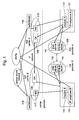
- FIG. 9 illustrates a communication network used for a conventional IP telephone system.
- IP telephone A 901 and IP telephone B 902 shown in FIG. 9 is described.
- IP telephone A 901 and IP telephone B 902 are using different providers and managed by CAs which are owned by different carriers.
- IP telephone A 901 and IP telephone B 902 have functions that enable voice communication via an IP network and a Public Switched Telephone Network (hereafter referred to as PSTN).
- PSTN Public Switched Telephone Network
- CA also has SIP (Session Initiation Protocol) server functions.
- IP telephone A 901 communicates with IP telephone B 902 , communication is established via the IP network or the PSTN.
- IP telephone A 901 transmits, to CA 904 owned by carrier A, the message “INVITE” which includes information regarding the destination terminal (IP telephone B 902 ) via modem A 903 .
- CA 904 searches for another CA that manages the destination terminal, since CA 904 does not manage the destination terminal. As a result of the search, CA 905 that is owned by carrier B is found, and the aforesaid message “INVITE” is transmitted from CA 904 to CA 905 .
- CA 905 transmits the message “INVITE” to IP telephone B 902 .
- IP telephone B 902 receives the message “INVITE” via modem B 906 .
- IP telephone B 902 receives the message “INVITE”
- messages specified by SIP are exchanged between IP telephone A 901 and IP telephone B 902 . Then, the two telephones are ready to communicate.
- IP telephone A 901 inputs the telephone number of IP telephone B 902 and places a call to IP telephone B 902 . Then, IP telephone B 902 receives a call from IP telephone A 901 via the PSTN. When the receiver of IP telephone B 902 is picked up, IP telephone A 901 and IP telephone B 902 are connected, and the two telephones are ready to communicate.
- FIG. 9 also shows a communication network between IP telephone A 901 and a terminal apparatus on a cellular phone network or the PSTN.
- voice date received from IP telephone A 901 is converted, at MG (Media Gateway) 907 , into a data format necessary for communication via the PSTN or the cellular phone network. Then, the converted data is transmitted to the PSTN or the cellular phone network via switchboard 908 .
- MG Media Gateway
- CA 904 When communication is attempted via the IP network and when there are some problems occurred within the IP network, CA 904 establishes communication via networks other than the IP network. For example, when communication is attempted via the PSTN, voice data received from IP telephone A 901 is transmitted to the PSTN via MG 907 and switchboard 908 as described above. Then, voice data is transmitted to IP telephone B 902 via switchboard 909 and MG 910 of carrier B.
- FIG. 10 is a sequence diagram to illustrate a communication network via the IP network.
- CA 904 transmits the message “INVITE” to CA 905 .
- CA 904 transmits the message “100 trying” to IP telephone A 901 .
- CA 905 transmits the message “INVITE” to IP telephone B 902 .
- CA 905 transmits the message “100 trying” to CA 904 .
- IP telephone B 902 Upon receiving the message “INVITE”, IP telephone B 902 transmits, to CA 905 , the message “100 trying” and then the message “180 Ringing”. At the same time as transmitting the message “180 Ringing”, IP telephone B 902 sounds a receiving tone.
- CA 905 transmits the message “180 Ringing” to CA 904 .
- CA 904 transmits the message “180 Ringing” to IP telephone A 901 .
- IP telephone A 901 then sounds a ringing tone in response to the message “180 Ringing”.
- IP telephone B 902 transmits, to CA 905 , the message “200 OK” to indicate a connection approval.
- CA 905 transmits the message “200 OK” to CA 904 .
- CA 904 transmits the message “200 OK” to IP telephone A 901 .
- IP telephone A 901 Upon receiving the message “200 OK”, IP telephone A 901 transmits the message “Acknowledge (hereafter referred to as ACK)” to CA 904 .
- CA 904 transmits the message “ACK” to CA 905 .
- CA 905 transmits the message “ACK” to IP telephone B 902 .
- IP telephone B 902 receives the message “ACK”, IP telephone A 901 and IP telephone B 902 are ready to communicate via the IP network.
- CA needs to relay all the messages, such as “INVITE” or “200 OK”, to destination terminals or other CAs. This puts an excessive workload on CA and will thus become a more serious problem in the future with the growth of IP telephones.
- predetermined signals e.g., SIP “INVITE” message
- CA handles all the signals transmitted via the PSTN as well as the IP network, which puts an excessive workload on CA.
- the present invention is provided to address the above-described problems.
- the objectives of the present invention are to both reduce the workload for CA on an IP network and provide an IP telephone system, an IP telephone apparatus and a calling method that facilitate the further development of IP telephone systems without requiring significant costs.
- FIG. 1 illustrates a configuration of a network to which the IP telephone system according to an embodiment of the present invention applies
- FIG. 2 illustrates a block diagram to describe a configuration of IP telephone A that structures the IP telephone system according to the embodiment of the present invention
- FIG. 3 illustrates a configuration of an ENUM server that structures the IP telephone system according to the embodiment of the present invention
- FIG. 4 illustrates an example of NAPTR resource records stored in DB of the ENUM server according to the embodiment of the present invention
- FIG. 5 illustrates a flow chart that describes an operation where IP telephone A places a call to IP telephone B in the IP telephone system according to the embodiment of the present invention
- FIG. 6 illustrates a sequence diagram that describes communication performed between IP telephone A and IP telephone B via the ENUM network in the IP telephone system according to the embodiment of the present invention
- FIG. 7 illustrates a sequence diagram that describes communication performed between IP telephone A and IP telephone B via the PSTN in the IP telephone system according to the embodiment of the present invention
- FIG. 8 illustrates a sequence diagram that describes communication performed between IP telephone A and IP telephone B via the IP network in the IP telephone system according to the embodiment of the present invention
- FIG. 9 illustrates a diagram that describes a communication network used for a conventional IP telephone.
- FIG. 10 illustrates a sequence diagram that describes communication performed via a conventional IP network.
- FIG. 1 illustrates a configuration of a network to which the IP telephone system according to the first embodiment of the present invention applies.
- FIG. 1 shows a network configuration necessary to establish communication between IP telephone A 101 and IP telephone B 102 that use different providers.
- IP telephone A 101 uses provider A 103 ;
- IP telephone B 102 uses provider B 104 .
- providers A and B are connected via the IP network.
- IP telephones A 101 and B 102 have functions which enable voice communication via the IP network or the PSTN.
- IP telephone A 101 and IP telephone B 102 are managed by IP telephone management servers, which are CAs, owned by different carriers.
- IP telephone A 101 is managed by CA 106 , which is owned by carrier A 105 ;
- IP telephone B 102 is managed by CA 108 , which is owned by carrier B 107 .
- CA 106 and CA 108 manage voice communication between IP telephone A 101 and IP telephone B 102 via the IP network.
- CA 106 and CA 108 have SIP (Session Initiation Protocol) server functions.
- Provider A 103 includes a terminal apparatus that functions as ENUM (E. 164 telephone Number Mapping) server 109 and DNS (Domain Name System) server 110 .
- ENUM server 109 or DNS server 110 can be configured as a personal computer (hereafter referred to as PC) equipped with a software which can manage a database.
- Provider B 104 as well as provider A 103 , comprises ENUM server 111 and DNS server 112 . Either the ENUM server or the DNS server can be configured to have both functions.
- IP telephone A 101 and IP telephone B 102 via the IP network or the PSTN as described in FIG. 1 .
- communication may be attempted via a network structured on the IP network (hereafter referred to as ENUM network) which enables voice communication on the IP network based on NAPTR resource records.
- ENUM network a network structured on the IP network
- IP network refers to a network that performs voice communication between IP telephones managed by CAs, which are owned by carriers.
- ENUM network refers to a network that performs voice communication between IP telephones based on NAPTR resource records provided by the ENUM server.
- IP telephone A 101 transmits, to CA 106 , the message “INVITE” which includes information regarding the destination terminal (IP telephone B 102 ) via modem A 113 .
- CA 106 searches for another CA that manages the destination terminal, since CA 106 does not manage the destination terminal. As a result of the search, CA 108 is found, and the aforesaid message “INVITE” is transmitted from CA 106 to CA 108 .
- CA 108 transmits the message “INVITE” to IP telephone B 102 .
- IP telephone B 102 receive the message “INVITE” via modem B 114 .
- messages specified by SIP are directly exchanged between IP telephone A 101 and IP telephone B 102 . Then, the two telephones are ready to communicate.
- IP telephone A 101 input the telephone number of IP telephone B 102 and places a call to IP telephone B 102 . Then, IP telephone B 102 receives the call from IP telephone A 101 via the PSTN. When the receiver of IP telephone B 102 is picked up, IP telephone A 101 and IP telephone B 102 are connected. Then, the two telephones are ready to communicate.
- IP telephone A 101 When communication is attempted via the PSTN, the calling telephone, IP telephone A 101 , in principle, needs to be set not to transmit a request to the ENUM server. When such a setup is not provided, IP telephone A 101 transmits, to ENUM server 109 , a request for a NAPTR resource record, which is later described.
- IP telephone A 101 transmits, to ENUM server 109 , a request for NAPTR resource record(s) of the destination terminal (IP telephone B 102 ).
- NAPTR resource record(s) register(s) SIP as a compatible service
- IP telephone A 101 transmits the message “INVITE” to IP telephone B 102 .
- IP telephone B 102 receives the message “INVITE”
- messages specified by SIP are exchanged between IP telephone A 101 and IP telephone B 102 . Then, the two telephones are ready to communicate.
- a detailed description of a communication process via the ENUM network is later provided.
- FIG. 1 also illustrates a communication network between IP telephone A 101 (IP telephone B 102 ) and a terminal on the cellular phone network or the PSTN.
- voice date received from IP telephone A 101 is converted, at MG (Media Gateway) 115 , into a data form necessary for communication via the PSTN or the cellular phone network. Then, the converted data is transmitted from MG 115 to the PSTN or the cellular phone network via switchboard 116 .
- MG Media Gateway
- CA 106 When communication is attempted between IP telephone A 101 and IP telephone B 102 via the IP network and when there are some problems occurred within the IP network, CA 106 ( 108 ) establishes communication via networks other than the IP network. For example, when communication is attempted via the PSTN, voice data received from IP telephone A 101 (IP telephone B 102 ) is transmitted, as described above, to the PSTN via MG 115 (MG 117 ) and switchboard 116 (switchboard 118 ). Then, voice data is transmitted to IP telephone B 102 (IP telephone A 101 ) via switchboard 118 (switchboard 116 ) (carrier A 105 ) and MG 117 (MG 116 ) of carrier B 107 .
- FIG. 2 illustrates a block diagram that describes a configuration of IP telephone A 101 that structures the IP telephone system according to the present embodiment.
- IP telephone B 102 has the same configuration.
- IP telephone A 101 is configured to connect control adapter 201 to ordinary telephone 202 .
- an ordinary telephone is a telephone that has no functions to make voice communication via the IP network and can only be communicated via the PSTN.
- Control adapter 201 according to the present embodiment can be configured to connect two ordinary telephones 202 and to function each telephone as an IP telephone.
- control adapter 201 can be configured to connect more than three telephones.
- Control adapter 201 includes CPU 203 that controls the entire operation of the apparatus.
- ROM 205 and RAM 206 are connected to CPU 203 via control bus 204 .
- ROM 205 stores a control program of control adapter 201 , which CPU 203 retrieves and executes.
- RAM 206 functions as a work memory when CPU 203 executes the control program.
- Control adapter 201 uses a flash ROM as ROM 205 and uses SDRAM as RAM 206 .
- Crosspoint mixer 208 is connected to CPU 203 via port 207 .
- Crosspoint mixer 208 has switching and mixing functions of talk lines for two telephones connected via an NCU, which is later described.
- NCU 209 is connected to crosspoint mixer 208 .
- NCU 209 connects and terminates a line with the opposite party by controlling telephone lines connected to control adapter 201 .
- A/D•D/ACODEC 210 is connected to CPU 203 via control bus 204 .
- A/D•D/ACODEC 210 performs an analog/digital conversion of voice data, which is input from telephone 202 , and compresses the converted data.
- a digital/analog conversion is performed to the decompressed data.
- LAN controller 211 and LAN controller 212 are connected to CPU 203 via controller bus 204 .
- LAN controller 211 controls signals exchanged between IP telephones and PCs or other devices connected via Ethernet (R).
- Ethernet (R) structures a network to which control adapter 201 is connected.
- LAN controller 211 assembles and analyzes packet data transmitted on a network.
- LAN controller 212 controls signals exchanged between the IP network and control adapter 201 and between the ENUM network and control adapter 201 via a DSL modem (modem A), which is connected to control adapter 201 via Ethernet (R).
- modem A DSL modem
- PSTN controller 213 is connected to CPU 203 via controller bus 204 .
- PSTN controller 213 controls signals exchanged between control adapter 201 as described above and the PSTN via analog interface (I/F) 214 .
- I/F analog interface
- IP telephone A 101 comprises the above configuration, instead of connecting an ordinary telephone to control adapter 201 , a control board having the functions of control adapter 201 is installed in IP telephone A 101 .
- FIG. 3 illustrates a configuration of ENUM server 109 that structures the IP telephone system according to the present embodiment.
- ENUM server 111 has the same configuration.
- ENUM server 109 includes CPU 301 that controls the entire operation of the server.
- Memory 302 is connected to CPU 301 .
- Memory 302 has ROM functions and RAM functions: ROM that stores the control program of ENUM server 109 , which CPU 301 retrieves and executes, and RAM that functions as a work memory when CPU 301 executes the control program.
- DB 303 is connected to CPU 301 .
- DB 303 stores NAPTR resource records, which are later described.
- CPU 301 receives, from IP telephone A 101 , a request based on standard E. 164, CPU 301 searches for corresponding NAPTR resource record(s) among data stored in DB 303 and returns corresponding NAPTR resource record(s) to IP telephone A 101 , which made the request.
- Input/output apparatus 304 is connected to CPU 301 .
- Input/output apparatus 304 for example, comprises an input apparatus such as a keyboard and an output apparatus such as a display.
- An input apparatus for example, is used to add and edit data stored in DB 303 .
- An output apparatus for example, is used by administrators of ENUM server 109 to confirm data stored in DB 303 .
- Network Interface (I/F) 305 is connected to CPU 301 .
- Network I/F 305 is an interface to connect ENUM server 109 to the Internet.
- FIG. 4 illustrates an example of NAPTR resource records stored in DB 303 of ENUM server 109 according to the present embodiment.
- DB 303 stores all NAPTR resource records including NAPTR resource record(s) that correspond(s) to IP telephone B 102 shown in FIG. 1 .
- Telephone number “0310000001” corresponds to IP telephone B 102 .
- DB 303 stores NAPTR resource record(s) that correspond(s) to domain name which is obtained from telephone numbers “0310000000”, “0310000001” and “0310000003”.
- URI “81310000000@tokyo.enumisp.jp” corresponds to domain name “0.0.0.0.0.0.0.1.3.1.8.e164.arpa” obtained from telephone number “0310000000”.
- URI “81310000003@tokyo.enumispjp” corresponds to domain name “3.0.0.0.0.0.0.1.3.1.8.e164.arpa” obtained from telephone number “0310000003”.
- DB 303 stores two NAPTR resource records that correspond to IP telephone B 102 .
- the NAPTR resource record in the top row contains “100” in the order filed. Also, “E2U+SIP”, which indicates compatibility with SIP, is contained in the service field. On the other hand, the NAPTR resource record in the second top row contains “200”, which indicates a lower priority than “100”, in the order field. Also, “E2U+tel”, which indicates that communication can be established via the PSTN, is contained in the service field.
- FIG. 5 is a flow chart that describes an operation where IP telephone A 101 places a call to IP telephone B 102 in the IP telephone system according to the present embodiment.
- DB 303 of ENUM server 109 needs to store the NAPTR resource records described in FIG. 4 .
- IP telephone A 101 places a call to IP telephone B 102
- the telephone number of IP telephone B 102 is input by the operator of IP telephone A 101 , and then a call-placement instruction is made. More specifically, telephone number “0310000001” or “10000001” with “03” omitted is input, and then a call-placement instruction is made.
- IP telephone A 101 After receiving the telephone number and then a call-placement instruction, IP telephone A 101 transmits, to ENUM server 109 , a request for NAPTR resource record(s) that correspond(s) to the telephone number (ST 501 ). More specifically, IP telephone A 101 converts the operator's input number “0310000001” into “+81-3-10000001” including the country code according to standard E. 164. Then, “+81310000001” is obtained, with + at the beginning, followed by the numbers. Then, non numerical symbols are deleted, and dots are inserted between the numbers, resulting in “8.1.3.1.0.0.0.0.0.0.1”. Next, the numbers are reversed, and a string e164.arpa is added at the end.
- IP telephone A 101 then transmits, to ENUM server 109 , a request for NAPTR resource record(s) that correspond(s) to the string.
- IP telephone A 101 waits for a response from ENUM server 109 (ST 502 ). When there is no response, IP telephone A 101 determines that the communication is unsuccessful and terminates the process. For example, no response is obtained when there is a communication line failure. On the other hand, DB 303 stores NAPTR resource record(s) that correspond(s) to IP telephone B 102 . Therefore, IP telephone A 101 receives a response.
- NAPTR resource record(s) that correspond(s) to the destination terminal is(are) stored (ST 503 ).
- DB 303 stores the NAPTR resource records that correspond to string “1.0.0.0.0.0.0.1.3.1.8.e164.arpa”, which corresponds to the telephone number of IP telephone B 102 . Therefore, it is determined that the NAPTR resource records corresponding to the destination terminal are stored.
- IP telephone A 101 When it is determined that SIP is returned as a compatible service, IP telephone A 101 starts communication using SIP Peer_to_Peer (ST 505 ). Accordingly, communication is directly performed between IP telephone A 101 and IP telephone B 102 via the ENUM network shown in FIG. 1 in accordance with the protocol specified by SIP.
- tel indicates that communication can be established via the PSTN. More specifically, it is determined the corresponding NAPTR resource records contain tel (E2U+tel) in the service field. The NAPTR resource records that correspond to string “1.0.0.0.0.0.0.1.3.1.8.e164.arpa” contain tel in the second top row of the service field. When no communication can be established for a certain reason, this NAPTR resource record including tel is returned. Therefore, in this case, it is determined that tel is returned as a compatible service at ST 506 . On the other hand, when it is determined that tel is not returned as a compatible service at ST 506 , IP telephone A 101 determines that the communication is unsuccessful and terminates the process.
- IP telephone A 101 When it is determined that tel is returned as a compatible service at ST 506 , IP telephone A 101 starts communication via the PSTN (ST 507 ). Accordingly, communication is directly performed between IP telephone A 101 and IP telephone B 102 via the PSTN shown in FIG. 1 .
- IP telephone A 101 places a call via CA 106 in accordance with the protocol specified by SIP (ST 508 ). More specifically, IP telephone A 101 transmits, to CA 106 , the message “INVITE” which includes information regarding the destination terminal.
- the process does not proceed to the following step.
- IP telephone B 102 When IP telephone B 102 is the destination terminal, CA 106 transmits, to CA 108 , the message “INVITE” as described above, since CA 106 does not manage IP telephone B 102 .
- IP telephone B 102 receives the message “INVITE” from CA 108 and returns a response message to IP telephone A 101 via CA 108 and CA 106 .
- IP telephone A 101 waits for a response from CA 106 .
- IP telephone A 101 determines that the communication is unsuccessful and terminates the process. In the same way as ST 502 , for example, no response is obtained when there is a communication line failure.
- a message is returned (ST 510 ).
- the message indicates that it is unsuccessful to establish communication with the destination terminal. For example, when three digit message beginning with one of the numbers “4”, “5” or “6”, i.e. “4**”, “5**” or “6**” is returned, it is determined whether it includes the message indicating that it is unsuccessful to establish communication with the destination terminal. When it is determined such a message is returned, IP telephone A 101 determines that the communication is unsuccessful and terminates the process.
- IP telephone A 101 starts communication using the IP network via CA (IP telephone), or communication through the IP network to the PSTN (IP-PSTN) (ST 511 ). Accordingly, communication is performed between IP telephone A 101 and IP telephone B 102 via the IP network shown in FIG. 1 in accordance with the protocol specified by SIP. Also, when no communication can be established between CA 106 and CA 108 for a certain reason, communication is performed via the PSTN.
- CA IP telephone
- IP-PSTN IP-PSTN
- FIGS. 6-8 show sequence diagrams that describe communication performed between IP telephone A 101 and IP telephone B 102 .
- FIG. 6 illustrates a sequence diagram that describes communication performed via the ENUM network shown in FIG. 1 ;
- FIG. 7 illustrates a sequence diagram that describes communication performed via the PSTN shown in FIG. 1 ;
- FIG. 8 illustrates a sequence diagram that describes communication performed via the IP network shown in FIG. 1 .
- IP telephone A 101 when IP telephone A 101 places a call to IP telephone B 102 , IP telephone A 101 first receives, from the operator, the telephone number of IP telephone B 102 and transmits, to ENUM server 109 , a request for NAPTR resource record(s) that correspond(s) to the telephone number.
- IP telephone B 102 corresponds to SIP.
- ENUM server 109 Upon receiving the request from IP telephone A 101 , ENUM server 109 returns, to IP telephone A 101 , a NAPTR resource record which indicates that IP telephone B 102 corresponds to SIP. IP telephone A 101 receives the NAPTR resource record and also determines a URI that corresponds to IP telephone B 102 .
- IP telephone A 101 Upon receiving the NAPTR resource record, IP telephone A 101 transmits, to DNS server 110 , a search request for the IP address of IP telephone B 102 . More specifically, IP telephone A 101 informs DNS server 110 of the URI that corresponds to IP telephone B 102 and transmits, to DNS server 110 , a request for the IP address that corresponds to the URI. After searching for the IP address of IP telephone B 102 , DNS server 110 informs IP telephone A 101 of the IP address corresponding to the URI.
- IP telephone A 101 Upon receiving the IP address of IP telephone B 102 , IP telephone A 101 directly transmits the message “INVITE” to the IP address of IP telephone B 102 without accessing CA. The message is transmitted from IP telephone A 101 to provider A, to provider B and to IP telephone B 102 .
- IP telephone B 102 Upon receiving the message “INVITE”, IP telephone B 102 transmits the message “100 trying” to IP telephone A 101 .
- IP telephone B 102 After transmitting the message “100 trying”, IP telephone B 102 transmits the message “180 Ringing” to IP telephone A 101 .
- IP telephone B 102 sounds a receiving tone at the same time as transmitting the message “180 Ringing”. IP telephone A 101 then sounds a ringing tone in response to the message “180 Ringing”.
- IP telephone B 102 When it is determined that, through the receiving tone, for example, a hook-off condition is detected at the receiver of IP telephone B 102 , IP telephone B 102 transmits, to IP telephone A 101 , the message “200 OK” to indicate a connection approval. Upon receiving the message “200 OK”, IP telephone A 101 transmits the message “ACK” to IP telephone B 102 . When IP telephone B 102 receives the message “ACK”, IP telephone A 101 and IP telephone B 102 are ready to communicate via the ENUM network shown in FIG. 1 .
- ENUM servers 109 and 111 When communication is attempted via the ENUM network, ENUM servers 109 and 111 bear a heavier workload while CAs 106 and 108 bear a lighter workload. However, ENUM servers 109 and 111 only need to return NAPTR resource record(s) in response to a request from the calling terminal, and calls are directly managed between the calling terminal and the destination terminal. Thus, unlike CAs 106 and 108 , ENUM servers 109 and 111 do not perform call management. Therefore, ENUM servers 109 and 111 do not bear an excessive workload unlike CAs 106 and 108 .
- IP telephone A 101 when IP telephone A 101 places a call to IP telephone B 102 , IP telephone A 101 first receives, from the operator, the telephone number of IP telephone B 102 and transmits, to ENUM server 109 , a request for NAPTR resource record(s) that correspond(s) to the telephone number.
- IP telephone B 102 corresponds to tel which indicates that communication can be established via the PSTN.
- ENUM server 109 Upon receiving the request from IP telephone A 101 , ENUM server 109 returns, to IP telephone A 101 , a NAPTR resource record which indicates that IP telephone B 102 corresponds to tel which indicates that communication can be established via the PSTN.
- IP telephone A 101 Upon receiving the NAPTR resource record, IP telephone A 101 places a call to IP telephone B 102 via the PSTN. A call is placed from IP telephone A 101 to IP telephone B 102 via the PSTN. In response to the call, IP telephone B 102 transmits, to IP telephone A 101 , a ringing signal at the same time as sounding a receiving tone. IP telephone A 101 sounds a ringing tone in response to the ringing signal.
- IP telephone B 102 When it is determined that, for example, the receiver of IP telephone B 102 is picked up in response to the receiving tone, IP telephone B 102 informs IP telephone A 101 that the receiver of IP telephone B 102 is picked up. At the same time, IP telephone A 101 and IP telephone B 102 are ready to communicate via the PSTN shown in FIG. 1 .
- IP telephone A 101 when communication is attempted via the PSTN, IP telephone A 101 first transmits, to ENUM server 109 , a request for NAPTR resource record(s).
- IP telephone B 102 receives a NAPTR resource record which contains tel which indicates that communication can be established with IP telephone B 102 via the PSTN
- IP telephone A 101 places a direct call to IP telephone B 102 via the PSTN.
- IP telephone A 101 transmits a predetermined signal to CA 106 (e.g., SIP “INVITE” message) when calls are placed. This reduces the workload for CA 106 .
- IP telephone A 101 when IP telephone A 101 places a call to IP telephone B 102 , IP telephone A 101 first receives, from the operator, the telephone number of IP telephone B 102 and transmits, to ENUM server 109 , a request for NAPTR resource record(s) that correspond(s) to the telephone number.
- NAPTR resource record(s) that correspond(s) to IP telephone B 102 is(are) not stored.
- ENUM server 109 Upon receiving the request from IP telephone A 101 , ENUM server 109 transmits a response which indicates that NAPTR resource record(s) that correspond(s) to IP telephone B 102 does(do) not exist.
- IP telephone A 101 Upon receiving the response which indicates such NAPTR resource record(s) does(do) not exist, IP telephone A 101 transmits the message “INVITE” to CA 106 .
- CA 106 transmits the message “INVITE” to CA 108 .
- CA 106 transmits the message “100 trying” to IP telephone A 101 .
- CA 108 transmits the message “INVITE” to IP telephone B 102 .
- CA 108 transmits the message “100 trying” to CA 106 .
- IP telephone B 102 Upon receiving the message “INVITE”, IP telephone B 102 transmits, to CA 108 , the message “100 trying” and then the message “180 Ringing”. At the same time as transmitting the message “180 Ringing”, IP telephone B 102 sounds a receiving tone. Similarly, CA 108 transmits the message “180 Ringing” to CA 106 . CA 106 transmits the message “180 Ringing” to IP telephone A 101 . IP telephone A 101 sounds a ringing tone in response to the message “180 Ringing”.
- IP telephone B 102 When it is determined, through the receiving tone, that, for example, a hook-off condition is detected at the receiver of IP telephone B 102 , IP telephone B 102 transmits, to CA 108 , the message “200 OK” to indicate a connection approval. Similarly, CA 108 transmits the message “200 OK” to CA 106 . CA 106 transmits the message “200 OK” to IP telephone A 101 .
- IP telephone A 101 Upon receiving the message “200 OK”, IP telephone A 101 transmits the message “ACK” to CA 106 . Similarly, CA 106 transmits the message “ACK” to CA 108 . CA 108 transmits the message “ACK” to IP telephone B 102 . When IP telephone B 102 receives the message “ACK”, IP telephone A 101 and IP telephone B 102 are ready to communicate via the IP network.
- CA 106 and CA 108 perform call management.
- CA 106 and CA 108 need to perform call management only when NAPTR resource record(s) that correspond(s) to the destination terminal is(are) not stored. This reduces the workload for CA 106 and CA 108 .
- IP telephone A 101 when IP telephone A 101 places a call to IP telephone B 102 , IP telephone A 101 first transmits, to ENUM server 109 , a request for NAPTR resource record(s) that correspond(s) to IP telephone B 102 .
- ENUM server 109 stores corresponding NAPTR resource record(s)
- call management is directly performed between IP telephone A 101 and IP telephone B 102 according to the NAPTR resource record.
- voice communication is performed via the ENUM network or the PSTN.
- CA 106 manages calls between IP telephone A 101 and IP telephone B 102 . Then, voice communication is performed via the IP network.
- the workload for CA 106 is reduced, and voice communication can be performed via the IP network without requiring CA 106 to perform call management.
- the workload for CA 106 is reduced while increasing the processing volume of voice communication via the IP network.
- ENUM server 109 only needs to return NAPTR resource record(s) without performing call management. Call management is directly performed between IP telephones A 101 and B 102 .
- the required cost will be lower than the cost required for communication by CA 106 .
- IP telephone systems can be diffused more and more without requiring a significant cost.
- ENUM server 109 and ENUM server 111 which configure the ENUM network, are owned by provider A 103 and provider B 104 , respectively.
- ENUM server 109 and ENUM server 111 can be structured on a network
- ENUM server 109 and ENUM server 111 do not necessary need to be owned by provider A 103 and provider B 104 .
- carrier A 105 and carrier B 107 can own ENUM server 109 and ENUM server 111 .
- provider A 103 and provider B 104 own ENUM server 109 and ENUM server 111 as a configuration of the present invention.
- providers provide IP telephone systems by leasing equipment from carriers.
- CA 106 and CA 108 execute only SIP as a VoIP protocol in the IP telephone system according to the present embodiment.
- the configuration is not limited to this setup. In other words, the configuration can accommodate H.323 as a VoIP protocol as well.
- voice is not limited to human voice. It also covers sounds in general, for example, modem signals modulated to voice bands and fax signals. Also, the telephone can be a fax apparatus as well.
- the IP telephone described above includes an IP telephone defined by the government and operated by a telecommunications provider. It also includes an IP telephone provided on a local network or a private network using TCP/IP or other computer network protocols.
Abstract
Description
Claims (15)
Applications Claiming Priority (2)
| Application Number | Priority Date | Filing Date | Title |
|---|---|---|---|
| JP2004-117245 | 2004-04-12 | ||
| JP2004117245A JP4469209B2 (en) | 2004-04-12 | 2004-04-12 | IP telephone system, IP telephone apparatus and calling method |
Publications (2)
| Publication Number | Publication Date |
|---|---|
| US20050226223A1 US20050226223A1 (en) | 2005-10-13 |
| US7957366B2 true US7957366B2 (en) | 2011-06-07 |
Family
ID=34934811
Family Applications (1)
| Application Number | Title | Priority Date | Filing Date |
|---|---|---|---|
| US11/082,796 Expired - Fee Related US7957366B2 (en) | 2004-04-12 | 2005-03-18 | IP telephone system, IP telephone apparatus and calling method |
Country Status (4)
| Country | Link |
|---|---|
| US (1) | US7957366B2 (en) |
| EP (1) | EP1589739B1 (en) |
| JP (1) | JP4469209B2 (en) |
| KR (1) | KR100675212B1 (en) |
Cited By (2)
| Publication number | Priority date | Publication date | Assignee | Title |
|---|---|---|---|---|
| US20120140764A1 (en) * | 2010-12-06 | 2012-06-07 | At&T Intellectual Property I, L.P. | Method and apparatus for configuring ip multimedia subsystem network elements |
| US20170111263A1 (en) * | 2014-08-29 | 2017-04-20 | Ntt Docomo, Inc. | Communication system, route selection apparatus, and route selection method |
Families Citing this family (15)
| Publication number | Priority date | Publication date | Assignee | Title |
|---|---|---|---|---|
| JP4328266B2 (en) * | 2004-06-28 | 2009-09-09 | パナソニック株式会社 | ENUM server, IP telephone apparatus and IP telephone system |
| JP4436208B2 (en) * | 2004-08-04 | 2010-03-24 | パナソニック株式会社 | IP telephone number inquiry system and IP telephone system |
| JP4522843B2 (en) | 2004-12-24 | 2010-08-11 | パナソニック株式会社 | IP telephone system, IP telephone apparatus, and file transfer method |
| US20060265509A1 (en) * | 2005-04-22 | 2006-11-23 | Pandit Shrihari B | Methods and systems for communicating voice, audio, video, text and/or multimedia data |
| US20070110049A1 (en) * | 2005-11-15 | 2007-05-17 | Nominum, Inc. | Data compression approach to telephone number management in domain name systems |
| US20070110051A1 (en) * | 2005-11-15 | 2007-05-17 | Nominum, Inc. | Numeric approach to telephone number management in domain name systems |
| US8406400B2 (en) * | 2007-06-12 | 2013-03-26 | At&T Intellectual Property I, Lp | Techniques for providing multimedia communication services to a subscriber |
| US8411670B2 (en) * | 2007-07-03 | 2013-04-02 | Motorola Mobility Llc | Reverse ENUM based routing for communication networks |
| US9258268B2 (en) | 2007-08-27 | 2016-02-09 | At&T Intellectual Property, I., L.P. | Methods and apparatus to dynamically select a peered voice over internet protocol (VoIP) border element |
| US9397862B2 (en) * | 2008-12-12 | 2016-07-19 | At&T Intellectual Property I, L.P. | Method and apparatus for completing a circuit switched service call in an internet protocol network |
| US8467322B2 (en) | 2010-04-19 | 2013-06-18 | Comcast Cable Communications, Llc | Inbound call screening for particular accounts |
| JP5553426B2 (en) * | 2011-06-03 | 2014-07-16 | 日本電信電話株式会社 | Number resolution system, number resolution method, and carrier ENUM server |
| US9936532B2 (en) * | 2013-10-04 | 2018-04-03 | At&T Intellectual Property I, L.P. | Method and apparatus for processing communication requests |
| JP6364385B2 (en) * | 2015-07-30 | 2018-07-25 | 日本電信電話株式会社 | ENUM system and load distribution method for ENUM system |
| JP6748614B2 (en) * | 2017-08-08 | 2020-09-02 | 日本電信電話株式会社 | Communication system and communication method |
Citations (26)
| Publication number | Priority date | Publication date | Assignee | Title |
|---|---|---|---|---|
| US6157636A (en) * | 1997-03-06 | 2000-12-05 | Bell Atlantic Network Services, Inc. | Network session management with gateway-directory services and authorization control |
| US6292478B1 (en) * | 1996-11-21 | 2001-09-18 | Bell Atlantic Network Services, Inc. | Telecommunications system |
| WO2001071989A1 (en) | 2000-03-24 | 2001-09-27 | World Axle Corporation | Information providing system |
| US6324264B1 (en) * | 1996-03-15 | 2001-11-27 | Telstra Corporation Limited | Method of establishing a communications call |
| US6347085B2 (en) * | 1996-08-16 | 2002-02-12 | Netspeak Corporation | Method and apparatus for establishing communications between packet-switched and circuit-switched networks |
| US20020027915A1 (en) | 2000-09-01 | 2002-03-07 | George Foti | System and method for address resolution in internet protocol (IP) -based networks |
| US6359880B1 (en) * | 1997-03-11 | 2002-03-19 | James E. Curry | Public wireless/cordless internet gateway |
| US6373817B1 (en) * | 1999-12-30 | 2002-04-16 | At&T Corp. | Chase me system |
| JP2002118601A (en) | 2000-10-06 | 2002-04-19 | World Axle Kk | Communication system and method |
| US20030007482A1 (en) * | 2001-07-06 | 2003-01-09 | Robert Khello | Method and apparatus for resolving an entity identifier into an internet address using a domain name system (DNS) server and an entity identifier portability database |
| KR20030022448A (en) | 2001-09-10 | 2003-03-17 | (주) 콘텔라 | Packet based indoor wireless communication system for providing zone based service contents |
| US20030074461A1 (en) * | 2001-10-09 | 2003-04-17 | I-Dns.Net International Pte. Ltd. | Method of mapping names or identifiers to telecommunications network resource locations |
| US20030088765A1 (en) * | 2001-11-02 | 2003-05-08 | General Instruments Corporation | Method and apparatus for transferring a communication session |
| US20030110292A1 (en) * | 2001-12-07 | 2003-06-12 | Yukiko Takeda | Address translator, message processing method and euipment |
| US6594254B1 (en) * | 1996-08-16 | 2003-07-15 | Netspeak Corporation | Domain name server architecture for translating telephone number domain names into network protocol addresses |
| US20030193486A1 (en) * | 2002-04-15 | 2003-10-16 | Estrop Stephen J. | Methods and apparatuses for facilitating processing of interlaced video images for progressive video displays |
| JP2003333106A (en) | 2002-05-16 | 2003-11-21 | Fujitsu Ltd | Telephone system for connecting public network and internet protocol network |
| WO2003103259A1 (en) | 2002-05-31 | 2003-12-11 | ソフトバンク株式会社 | Terminal connection device, connection control device, and multi-function telephone terminal |
| WO2003107627A1 (en) | 2002-06-14 | 2003-12-24 | France Telecom Sa | System for consulting and/or updating dns servers and/or ldap directories |
| US20040057421A1 (en) * | 2002-09-19 | 2004-03-25 | Fuji Xerox Co., Ltd. | Communications terminal unit and method for controlling the same |
| KR20040028333A (en) | 2002-09-30 | 2004-04-03 | 주식회사 케이티 | Method for ENUM call identification by NPDB |
| US20040193725A1 (en) * | 2003-03-25 | 2004-09-30 | Jose Costa-Requena | Optimal location service for managing next hop addressing for messages associated with multiple address schemes |
| US20040199649A1 (en) * | 2003-03-31 | 2004-10-07 | Teemu Tarnanen | System and method to provide interoperability between session initiation protocol and other messaging services |
| US20040260824A1 (en) * | 2001-05-23 | 2004-12-23 | Francois Berard | Internet telephony call agent |
| US6839421B2 (en) * | 2001-10-29 | 2005-01-04 | Telefonaktiebolaget Lm Ericsson (Publ) | Method and apparatus to carry out resolution of entity identifier in circuit-switched networks by using a domain name system |
| US7644181B2 (en) * | 2002-07-02 | 2010-01-05 | Telefonaktiebolaget L M Ericsson (Publ) | Method for routing a service request in a telecommunication system |
-
2004
- 2004-04-12 JP JP2004117245A patent/JP4469209B2/en not_active Expired - Fee Related
-
2005
- 2005-03-18 US US11/082,796 patent/US7957366B2/en not_active Expired - Fee Related
- 2005-04-06 EP EP20050007543 patent/EP1589739B1/en not_active Expired - Fee Related
- 2005-04-11 KR KR20050030104A patent/KR100675212B1/en not_active IP Right Cessation
Patent Citations (31)
| Publication number | Priority date | Publication date | Assignee | Title |
|---|---|---|---|---|
| US6324264B1 (en) * | 1996-03-15 | 2001-11-27 | Telstra Corporation Limited | Method of establishing a communications call |
| US6594254B1 (en) * | 1996-08-16 | 2003-07-15 | Netspeak Corporation | Domain name server architecture for translating telephone number domain names into network protocol addresses |
| US6347085B2 (en) * | 1996-08-16 | 2002-02-12 | Netspeak Corporation | Method and apparatus for establishing communications between packet-switched and circuit-switched networks |
| US6292478B1 (en) * | 1996-11-21 | 2001-09-18 | Bell Atlantic Network Services, Inc. | Telecommunications system |
| US6157636A (en) * | 1997-03-06 | 2000-12-05 | Bell Atlantic Network Services, Inc. | Network session management with gateway-directory services and authorization control |
| US6359880B1 (en) * | 1997-03-11 | 2002-03-19 | James E. Curry | Public wireless/cordless internet gateway |
| US6373817B1 (en) * | 1999-12-30 | 2002-04-16 | At&T Corp. | Chase me system |
| US20040052346A1 (en) | 2000-03-24 | 2004-03-18 | Masataka Ohta | Information providing system |
| WO2001071989A1 (en) | 2000-03-24 | 2001-09-27 | World Axle Corporation | Information providing system |
| US6917612B2 (en) * | 2000-09-01 | 2005-07-12 | Telefonaktiebolaged L M Ericsson | System and method for address resolution in internet protocol (IP)-based networks |
| US20020027915A1 (en) | 2000-09-01 | 2002-03-07 | George Foti | System and method for address resolution in internet protocol (IP) -based networks |
| JP2002118601A (en) | 2000-10-06 | 2002-04-19 | World Axle Kk | Communication system and method |
| US20040260824A1 (en) * | 2001-05-23 | 2004-12-23 | Francois Berard | Internet telephony call agent |
| US20030007482A1 (en) * | 2001-07-06 | 2003-01-09 | Robert Khello | Method and apparatus for resolving an entity identifier into an internet address using a domain name system (DNS) server and an entity identifier portability database |
| KR20030022448A (en) | 2001-09-10 | 2003-03-17 | (주) 콘텔라 | Packet based indoor wireless communication system for providing zone based service contents |
| US20030074461A1 (en) * | 2001-10-09 | 2003-04-17 | I-Dns.Net International Pte. Ltd. | Method of mapping names or identifiers to telecommunications network resource locations |
| US6839421B2 (en) * | 2001-10-29 | 2005-01-04 | Telefonaktiebolaget Lm Ericsson (Publ) | Method and apparatus to carry out resolution of entity identifier in circuit-switched networks by using a domain name system |
| US20030088765A1 (en) * | 2001-11-02 | 2003-05-08 | General Instruments Corporation | Method and apparatus for transferring a communication session |
| US20030110292A1 (en) * | 2001-12-07 | 2003-06-12 | Yukiko Takeda | Address translator, message processing method and euipment |
| US20030193486A1 (en) * | 2002-04-15 | 2003-10-16 | Estrop Stephen J. | Methods and apparatuses for facilitating processing of interlaced video images for progressive video displays |
| JP2003333106A (en) | 2002-05-16 | 2003-11-21 | Fujitsu Ltd | Telephone system for connecting public network and internet protocol network |
| WO2003103259A1 (en) | 2002-05-31 | 2003-12-11 | ソフトバンク株式会社 | Terminal connection device, connection control device, and multi-function telephone terminal |
| US20060013195A1 (en) | 2002-05-31 | 2006-01-19 | Softbank Corp. | Terminal connection device, connection control device, and multi-function telephone terminal |
| EP1511282A1 (en) | 2002-05-31 | 2005-03-02 | Softbank Corporation | Terminal connection device, connection control device, and multi-function telephone terminal |
| WO2003107627A1 (en) | 2002-06-14 | 2003-12-24 | France Telecom Sa | System for consulting and/or updating dns servers and/or ldap directories |
| US20050182781A1 (en) | 2002-06-14 | 2005-08-18 | Bertrand Bouvet | System for consulting and/or updating dns servers and/or ldap directories |
| US7644181B2 (en) * | 2002-07-02 | 2010-01-05 | Telefonaktiebolaget L M Ericsson (Publ) | Method for routing a service request in a telecommunication system |
| US20040057421A1 (en) * | 2002-09-19 | 2004-03-25 | Fuji Xerox Co., Ltd. | Communications terminal unit and method for controlling the same |
| KR20040028333A (en) | 2002-09-30 | 2004-04-03 | 주식회사 케이티 | Method for ENUM call identification by NPDB |
| US20040193725A1 (en) * | 2003-03-25 | 2004-09-30 | Jose Costa-Requena | Optimal location service for managing next hop addressing for messages associated with multiple address schemes |
| US20040199649A1 (en) * | 2003-03-31 | 2004-10-07 | Teemu Tarnanen | System and method to provide interoperability between session initiation protocol and other messaging services |
Non-Patent Citations (16)
| Title |
|---|
| "Report of the Department of State ITAC-T Advisory Committee Study Group A Ad Hoc on ENUM," Online, Jun. 6, 2001. |
| Blank et al., "ENUM-Domains bei der DENIC Eg" Online, Mar. 10, 2004 pp. 1-29 XP002375278, retrieved from the Internet: URL: www.denic.de/media/pdf/enum/veranstaltungen/pre-reader-20040316.pdf, retrieved on Mar. 29, 2006, together with a partial English language translation of the same. |
| Blank et al., "ENUM-Domains bei der DENIC Eg" Online, Mar. 10, 2004 pp. 1-29 XP002375278, retrieved from the Internet: URL: www.denic.de/media/pdf/enum/veranstaltungen/pre-reader—20040316.pdf, retrieved on Mar. 29, 2006, together with a partial English language translation of the same. |
| English language Abstract of JP 2002-118601, Apr. 19, 2002. |
| English language Abstract of JP 2003-333106. |
| English Language Abstract of KR 2003-0022448. |
| English Language Abstract of KR 2004-0028333. |
| English language abstract of WO 0171989 (A1). |
| Faltstrom Cisco Systems Inc.,et al., "The E.164 to Uniform Resource Identifiers (URI) Dynamic Delegation Discovery System (DDDS) Application (ENUM); rfc3761.txt," IETF Standard, Internet Engineering Task Force, IETF, CH, Apr. 2004 XP015009541. |
| Faltstrom, Cisco Systems Inc.,"E.164 number and DNS; rfc2916.txt," IETF Standard, Internet Engineering Task Force, IETF, CH, Sep. 2000 XP015008699. |
| Lind, "ENUM Call Flows for VoIP Internetworking; draft-lind-enum-callflows-03.txt," IETF Standard-Working-Draft.Internet Engineering Task Force, IETF, CH, No. 3, Feb. 2002, XP015004214. |
| Network Working Group M. Mealling R. Daniel Request for Comments: 2915 Updates: 2168, Sep. 2000. * |
| U.S. Appl. No. 10/995,503 to Miyajima et al., which was filed on Nov. 24, 2004. |
| U.S. Appl. No. 10/995,506 to Miyajima et al., which was filed on Nov. 24, 2004. |
| U.S. Appl. No. 10/995,507 to Miyajima et al., which was filed on Nov. 24, 2004. |
| U.S. Appl. No. 11/082,710 to Kobayshi et al., which was filed on Mar. 18, 2005. |
Cited By (4)
| Publication number | Priority date | Publication date | Assignee | Title |
|---|---|---|---|---|
| US20120140764A1 (en) * | 2010-12-06 | 2012-06-07 | At&T Intellectual Property I, L.P. | Method and apparatus for configuring ip multimedia subsystem network elements |
| US8547966B2 (en) * | 2010-12-06 | 2013-10-01 | At&T Intellectual Property I, L.P. | Method and apparatus for configuring IP multimedia subsystem network elements |
| US20170111263A1 (en) * | 2014-08-29 | 2017-04-20 | Ntt Docomo, Inc. | Communication system, route selection apparatus, and route selection method |
| US10050871B2 (en) * | 2014-08-29 | 2018-08-14 | Ntt Docomo, Inc. | Communication system, route selection apparatus, and route selection method |
Also Published As
| Publication number | Publication date |
|---|---|
| KR100675212B1 (en) | 2007-01-26 |
| JP4469209B2 (en) | 2010-05-26 |
| EP1589739A2 (en) | 2005-10-26 |
| US20050226223A1 (en) | 2005-10-13 |
| EP1589739A3 (en) | 2006-09-20 |
| JP2005303679A (en) | 2005-10-27 |
| EP1589739B1 (en) | 2014-02-26 |
| KR20060045590A (en) | 2006-05-17 |
Similar Documents
| Publication | Publication Date | Title |
|---|---|---|
| US7957366B2 (en) | IP telephone system, IP telephone apparatus and calling method | |
| EP1580974B1 (en) | Internet telephone calling system and corresponding method | |
| AU2011201143B2 (en) | Caller-callee association of a plurality of networked devices | |
| US6807166B1 (en) | Gateway for internet telephone | |
| US8089954B2 (en) | IP telephone system, IP telephone apparatus and communications method | |
| US7653049B2 (en) | IP telephone system, IP telephone apparatus and calling method | |
| EP1949649B1 (en) | Using pstn to communicate ip addresses for point-to-point text, voice, video, or data communication | |
| US20080144578A1 (en) | Communication system | |
| EP1592219B1 (en) | IP telephone system, IP telephone apparatus and calling method | |
| EP1626562B1 (en) | IP telephone system, IP telephone apparatus and method for performing telephone conference | |
| US7756257B2 (en) | SIP enabled device identification | |
| US20040052346A1 (en) | Information providing system | |
| US8711841B2 (en) | Communication system | |
| EP1619868A2 (en) | IP telephone system, ENUM server and method for performing telephone conference | |
| US20080101564A1 (en) | Communication system | |
| EP0998109B1 (en) | A communication network utilizing autonomous servers to establish a communication session | |
| US7154878B1 (en) | Integrated network | |
| KR20030063063A (en) | Method and Apparatus for Exchanging a Rout of Telephone Call by Using an IP-PBX | |
| KR20080043918A (en) | Private branch exchange system for servicing additional function between external terminal and accommodation terminal in communication over voip |
Legal Events
| Date | Code | Title | Description |
|---|---|---|---|
| AS | Assignment |
Owner name: MATSUSHITA ELECTRIC INDUSTRIAL CO., LTD., JAPAN Free format text: ASSIGNMENT OF ASSIGNORS INTEREST;ASSIGNORS:KAIZAWA, YASUHITO;KOBAYASHI, KAZUTO;MIYAJIMA, AKIRA;REEL/FRAME:016396/0551;SIGNING DATES FROM 20050222 TO 20050228 Owner name: MATSUSHITA ELECTRIC INDUSTRIAL CO., LTD., JAPAN Free format text: ASSIGNMENT OF ASSIGNORS INTEREST;ASSIGNORS:KAIZAWA, YASUHITO;KOBAYASHI, KAZUTO;MIYAJIMA, AKIRA;SIGNING DATES FROM 20050222 TO 20050228;REEL/FRAME:016396/0551 |
|
| AS | Assignment |
Owner name: PANASONIC CORPORATION, JAPAN Free format text: CHANGE OF NAME;ASSIGNOR:MATSUSHITA ELECTRIC INDUSTRIAL CO., LTD.;REEL/FRAME:021897/0653 Effective date: 20081001 Owner name: PANASONIC CORPORATION,JAPAN Free format text: CHANGE OF NAME;ASSIGNOR:MATSUSHITA ELECTRIC INDUSTRIAL CO., LTD.;REEL/FRAME:021897/0653 Effective date: 20081001 |
|
| STCF | Information on status: patent grant |
Free format text: PATENTED CASE |
|
| FEPP | Fee payment procedure |
Free format text: PAYOR NUMBER ASSIGNED (ORIGINAL EVENT CODE: ASPN); ENTITY STATUS OF PATENT OWNER: LARGE ENTITY |
|
| FPAY | Fee payment |
Year of fee payment: 4 |
|
| FEPP | Fee payment procedure |
Free format text: MAINTENANCE FEE REMINDER MAILED (ORIGINAL EVENT CODE: REM.); ENTITY STATUS OF PATENT OWNER: LARGE ENTITY |
|
| LAPS | Lapse for failure to pay maintenance fees |
Free format text: PATENT EXPIRED FOR FAILURE TO PAY MAINTENANCE FEES (ORIGINAL EVENT CODE: EXP.); ENTITY STATUS OF PATENT OWNER: LARGE ENTITY |
|
| STCH | Information on status: patent discontinuation |
Free format text: PATENT EXPIRED DUE TO NONPAYMENT OF MAINTENANCE FEES UNDER 37 CFR 1.362 |
|
| FP | Lapsed due to failure to pay maintenance fee |
Effective date: 20190607 |