US7903554B1 - Leaking component link traffic engineering information - Google Patents
Leaking component link traffic engineering information Download PDFInfo
- Publication number
- US7903554B1 US7903554B1 US12/080,748 US8074808A US7903554B1 US 7903554 B1 US7903554 B1 US 7903554B1 US 8074808 A US8074808 A US 8074808A US 7903554 B1 US7903554 B1 US 7903554B1
- Authority
- US
- United States
- Prior art keywords
- link
- network device
- label
- packet network
- bandwidth
- Prior art date
- Legal status (The legal status is an assumption and is not a legal conclusion. Google has not performed a legal analysis and makes no representation as to the accuracy of the status listed.)
- Active, expires
Links
Images


Classifications
-
- H—ELECTRICITY
- H04—ELECTRIC COMMUNICATION TECHNIQUE
- H04L—TRANSMISSION OF DIGITAL INFORMATION, e.g. TELEGRAPHIC COMMUNICATION
- H04L47/00—Traffic control in data switching networks
- H04L47/70—Admission control; Resource allocation
- H04L47/72—Admission control; Resource allocation using reservation actions during connection setup
- H04L47/724—Admission control; Resource allocation using reservation actions during connection setup at intermediate nodes, e.g. resource reservation protocol [RSVP]
-
- H—ELECTRICITY
- H04—ELECTRIC COMMUNICATION TECHNIQUE
- H04L—TRANSMISSION OF DIGITAL INFORMATION, e.g. TELEGRAPHIC COMMUNICATION
- H04L45/00—Routing or path finding of packets in data switching networks
- H04L45/02—Topology update or discovery
- H04L45/026—Details of "hello" or keep-alive messages
-
- H—ELECTRICITY
- H04—ELECTRIC COMMUNICATION TECHNIQUE
- H04L—TRANSMISSION OF DIGITAL INFORMATION, e.g. TELEGRAPHIC COMMUNICATION
- H04L45/00—Routing or path finding of packets in data switching networks
- H04L45/02—Topology update or discovery
- H04L45/10—Routing in connection-oriented networks, e.g. X.25 or ATM
-
- H—ELECTRICITY
- H04—ELECTRIC COMMUNICATION TECHNIQUE
- H04L—TRANSMISSION OF DIGITAL INFORMATION, e.g. TELEGRAPHIC COMMUNICATION
- H04L45/00—Routing or path finding of packets in data switching networks
- H04L45/302—Route determination based on requested QoS
-
- H—ELECTRICITY
- H04—ELECTRIC COMMUNICATION TECHNIQUE
- H04L—TRANSMISSION OF DIGITAL INFORMATION, e.g. TELEGRAPHIC COMMUNICATION
- H04L47/00—Traffic control in data switching networks
- H04L47/70—Admission control; Resource allocation
- H04L47/74—Admission control; Resource allocation measures in reaction to resource unavailability
- H04L47/748—Negotiation of resources, e.g. modification of a request
-
- H—ELECTRICITY
- H04—ELECTRIC COMMUNICATION TECHNIQUE
- H04L—TRANSMISSION OF DIGITAL INFORMATION, e.g. TELEGRAPHIC COMMUNICATION
- H04L47/00—Traffic control in data switching networks
- H04L47/70—Admission control; Resource allocation
- H04L47/76—Admission control; Resource allocation using dynamic resource allocation, e.g. in-call renegotiation requested by the user or requested by the network in response to changing network conditions
- H04L47/762—Admission control; Resource allocation using dynamic resource allocation, e.g. in-call renegotiation requested by the user or requested by the network in response to changing network conditions triggered by the network
-
- H—ELECTRICITY
- H04—ELECTRIC COMMUNICATION TECHNIQUE
- H04L—TRANSMISSION OF DIGITAL INFORMATION, e.g. TELEGRAPHIC COMMUNICATION
- H04L2212/00—Encapsulation of packets
-
- H—ELECTRICITY
- H04—ELECTRIC COMMUNICATION TECHNIQUE
- H04L—TRANSMISSION OF DIGITAL INFORMATION, e.g. TELEGRAPHIC COMMUNICATION
- H04L45/00—Routing or path finding of packets in data switching networks
- H04L45/50—Routing or path finding of packets in data switching networks using label swapping, e.g. multi-protocol label switch [MPLS]
Definitions
- the present disclosure relates generally to packet networks, and more particularly to the operation of traffic-engineered label-switched paths within such networks.
- nodes In a packet network, “nodes” or “routers” share network address information that allows each node or router to forward packets toward their respective destination networks.
- each node For networks defined using the Internet Protocol, each node is provisioned with a network address that identifies the particular network the system is on, and with a system or host address that uniquely identifies the node. These addresses are shared among neighboring nodes to allow each router to build a “tree” with itself as the root node and next-hop paths from itself to every address on the network.
- OSPF Open Shortest Path First
- IS-IS Intermediate System to Intermediate System
- IETF Internet Engineering Task Force
- RFC 2740 OSPF for IPv6
- ISO International Organization for Standardization
- OSPF and IS-IS are examples of link-state protocols.
- a “link” can be considered to be an interface or port on a router, or an aggregation of such interfaces or ports that are treated as a single link by the routing protocol ( FIG. 1A shows a logical link LL 5 that is an aggregation of three physical links).
- the state of each link contains a description of the interface and what routers/networks are reachable through that link.
- a link-state database would contain the IP address of the interface/device, the subnet mask and other information describing the network, a list of routers connected to that network, a cost of sending packets across that interface, etc.
- OSPF routers use link-state advertisements (LSAs) to share information from their link-state databases with neighboring routers in the same autonomous system.
- LSAs link-state advertisements
- the router Whenever an interface is brought up or a change in routing information known to the router occurs, the router generates a LSA to inform its neighbors of the new or changed link-state information.
- a neighbor router receives the LSA, it updates its own link-state database and then propagates the information in another LSA to its neighbors. Thus the LSA is flooded to all routers, and all routers contain the same link-state database.
- a router Whenever a router receives an update to its link-state database, it uses a shortest path algorithm (the Dijkstra algorithm) to calculate a shortest path tree to all destinations, based on the accumulated costs associated with the links used to reach each destination.
- the shortest path tree will differ for each router, as each places itself at the root of the tree, but all routers should agree with each other as to routes. In other words, no routing loops should exist where node A thinks that a destination should be reached through a node B, and node B thinks that the destination should be reached through node A.
- FIG. 1A depicts two areas A 0 , A 1 of an autonomous system (AS) 100 . Every AS must have an area 0 or backbone area. Generally, all other areas connect to the backbone area, although provisions exist for transit areas.
- AS autonomous system
- Routers are classified according to their position in the AS.
- An internal router has all of its interfaces in the same area.
- routers LSR 1 and LSR 2 are internal routers.
- An area border router (ABR) has interfaces in multiple areas of the AS.
- LER 1 has two interfaces (L 2 and L 3 ) in area A 1 , and at least one interface in another area (L 0 in area A 0 ), and is thus an ABR.
- An autonomous system boundary router (ASBR) has at least one interface in an area of the AS and at least one interface to another AS or running another routing protocol. The ASBR selectively redistributes information received from the foreign network/protocol within OSPF.
- routers LER 1 and LER 2 are ASBRs. Both LER 1 and LER 2 communicate, over link L 1 and links L 9 and L 10 , respectively, with routers (not shown) outside of the AS using an external gateway protocol, such as Border Gateway Protocol (BGP).
- Border Gateway Protocol BGP
- OSPF and IS-IS provide one method to direct traffic across a packet network
- protocols such as Multi-Protocol Label Switching (MPLS) allow packets to be routed across a packet network using small “labels” or “tags” inserted in the packets.
- MPLS Multi-Protocol Label Switching
- Neighboring routers agree beforehand that packets transmitted from an upstream router to a downstream router with a given label will be forwarded along a unidirectional “label-switched path” (LSP) that has been pre-arranged.
- LSP label-switched path
- a LSP is essentially a tunnel set up between two “label edge routers” (LERs), one of which receives the packets and inserts the first label, and the other of which removes the last label and forwards the packet using other means (such as a traditional routing protocol).
- LERs label edge routers
- Other routers along the path are termed “label-switching routers” (LSRs), due to their function of switching incoming labels they recognize for outgoing labels that their downstream neighbor will recognize.
- LSRs label-switching routers
- the packets traversing a LSP belong to a common “Forwarding Equivalent Class” (FEC) that can be routed efficiently using the two LERs as points along the routing path.
- FEC Forming Equivalent Class
- MPLS LSPs One use for MPLS LSPs is in the operation of a traffic-engineered network. Using shortest-path routing algorithms, it is difficult to guide specific traffic towards underutilized paths, and thus the “shortest” paths tend to be overutilized, decreasing network performance as a whole.
- TE traffic-engineered
- different constraints such as link utilization and which links can guarantee a given bandwidth, latency, etc., enter in to the selection of a path, e.g., using a “constraint-based routing” algorithm. Once an appropriate path is found for a traffic stream, an MPLS traffic-engineered LSP tunnel can be set up to forward that traffic stream.
- an ingress endpoint In order to use constraint-based routing to reach a remote endpoint, an ingress endpoint must know more than just the traditional IGP link state information.
- the nodes in a TE network flood TE LSAs throughout the network. For instance, LSR 1 sends TE LSAs to LER 1 , LSR 2 , and LSR 3 , reporting traffic engineering information on outgoing links L 2 , L 4 , and LL 5 .
- LSR 1 also floods TE LSAs that it receives from LER 1 , LSR 2 , and LSR 3 to the others in this group.
- LER 1 upon receiving TE LSAs, builds a Traffic Engineering Database (TED) for area A 1 , from which it can construct MPLS LSPs.
- TED Traffic Engineering Database
- FIG. 2 shows the general format of an OSPF TE LSA 200 .
- TE LSA 200 contains a standard OSPF LSA header, marked as an Opaque TE LSA.
- Each TE LSA contains two TLVs (Type-Length-Value fields)—a router address TLV (which identifies the router that generated the LSA) and a link TLV.
- the link TLV contains between two and nine sub-TLVs, of the types shown in FIG. 2 . These TLVs describe the link, its traffic engineering attributes, and its bandwidth attributes.
- An edge router can examine its link-state database and traffic engineering database and determine a path across a network area that it believes to be a good fit for a traffic class.
- the edge router can attempt to set up this path by issuing an MPLS-TE path message, using protocol packets such as Resource ReSerVation Protocol (RSVP) packets, including an Explicit Route Object that specifies the path to be taken.
- FIG. 1C shows an example.
- LER 1 determines that a given traffic class should be traffic engineered on an explicit route LSR 1 -LSR 2 -LER 2 .
- LER 1 generates an RSVP path message to LSR 1 . Assuming LSR 1 can meet the bandwidth request on LL 5 , LSR 1 propagates the RSVP path message to LSR 2 . When LSR 2 can also meet the bandwidth request on L 7 , LSR 2 propagates the RSVP path message to LER 2 .
- FIG. 1D shows an example.
- LER 2 generates an RSVP return reservation request (RREQ) that identifies the RSVP path message of FIG. 1C , and specifies a label to be applied to packets sent over this LSP to LER 2 .
- LER 2 sends RREQ to LSR 2 , which reserves the requested bandwidth on L 7 .
- LSR 2 generates an RSVP RREQ packet with a label to be applied to packets sent over this LSP to LSR 2 , and sends RREQ to LSR 1 .
- LSR 2 creates an entry in its forwarding database, identifying the labels to be swapped for the LSP, and an outgoing interface (link L 7 ) to be used.
- LSR 1 performs similar functions as LSR 2 .
- FIG. 1E shows an example of the MPLS LSP segments, where LSR 1 has instructed LER 1 to use an MPLS label T 1 , LSR 2 has instructed LSR 1 to use an MPLS label T 2 , and LER 2 has instructed LSR 2 to use an MPLS label T 3 .
- LER 1 receives packets of the requested forwarding equivalence class FEC 1 , e.g., on link L 1 .
- the packets are modified with an MPLS header to traverse the links L 2 , LL 5 , and L 7 , respectively, with labels T 1 , T 2 , and T 3 inserted respectively by LER 1 , LSR 1 , and LSR 2 .
- LER 2 removes the MPLS header and forwards the packets FEC 1 out an appropriate interface, e.g., L 9 , using an appropriate IP routing protocol.
- MPLS, RSVP, and Traffic Engineering are complex inter-related subjects with voluminous design documents that describe operation in further detail.
- the following Internet Engineering Task Force (IETF) documents describe various features useful in understanding the framework underlying the embodiments in additional detail, and are incorporated herein by reference: IETF Request For Comments (RFC) 2205, S. Berson et al., “Resource ReSerVation Protocol (RSVP),” September 1997; IETF RFC 2702, D. Awduche et al., “Requirements for Traffic Engineering Over MPLS,” September 1999; IETF RFC 3031, E. Rosen et al., “Multiprotocol Label Switching Architecture,” January 2001; IETF RFC 3209, D.
- FIGS. 1A-1F show a network area and its use to create a prior art traffic-engineered label-switched path across the network area.
- FIG. 2 illustrates a prior art traffic engineering link state advertisement
- FIG. 3 illustrates a traffic engineering link state advertisement according to an embodiment.
- FIGS. 4 and 5 contain flowcharts for operation of a label-switching router embodiment.
- FIGS. 6A-6C illustrate an operation example of an embodiment.
- FIG. 7 depicts a block diagram showing components used by an LSR embodiment performing hardware-based label-swapping.
- the LSP operates across a logical link LL 5 between LSR 1 and LSR 2 .
- a link can be formed between two adjacent switch/routers that have multiple physical channels (separate wires or fibers, separate wavelength channels, etc.) connecting the two.
- the two adjacent switch/routers form a link aggregation group (LAG) that the two switch/routers manage between themselves.
- the routers then advertise the multiple physical channels to other devices in the area (e.g., using OSPF, IS-IS, etc.) as a single interface (e.g., using a MAC address from one of the interfaces).
- This advertised interface has a bandwidth capability that is roughly the sum of the bandwidths of the component links. The remainder of the bandwidth is spent in a small overhead exchange comprising link aggregation control protocol (LACP) packets that maintain the logical aggregation.
- LACP link aggregation control protocol
- the transmitting end of a LAG link distributes the outbound packets for the logical link among the physical component links of the LAG using a hash of the packet header fields.
- the receiving end merges (usually physically, but possibly only logically when the component link receivers supply packets to different packet processors in a distributed system) the received packets from the physical component links for processing and forwarding toward their respective destinations.
- LAG implementations use a hash-based function to distribute packets across the LAG membership.
- the hash-based function creates a hash key from packet information such as source/destination addresses, and then uses a hash value created from the hash key to select an interface for each packet. This ensures that packets from a common packet flow follow the same physical link across the LAG, and therefore do not become out of order from traversing the LAG on different links.
- a router operating a LAG creates link state advertisements for reachability and traffic engineering parameters based on the bandwidth capacity of the entire LAG. LERs can then reserve a portion of the aggregate bandwidth on the LAG for their LSP tunnel requirements.
- a LSR operating a LAG has the capability to advertise—for each of the LAG's component links and not just for the LAG as an entity—TE information (such as maximum bandwidth, reservable bandwidth, average bandwidth, unreserved bandwidth, etc.) in its TE LSAs.
- TE information such as maximum bandwidth, reservable bandwidth, average bandwidth, unreserved bandwidth, etc.
- a LER desiring to set up a LSP through the LSR can then consult this component link information in its TED, and select an individual link of the LAG for use in the LSP based on the individual link loading, etc.
- the LER when requesting an LSP with an explicit route, can then request a reservation of bandwidth on a particular LAG component link that seems appropriate for the LSP traffic requirements.
- the LSR has the ability to grant the bandwidth reservation for a particular LSP/component link combination.
- the LSR then removes traffic for that LSP from LAG hashing behavior by creating a routing entry pointing to the specifically requested component link interface, instead of the LAG interface.
- this allows the LER to manage the reservable portion of the LAG bandwidth according to its own traffic considerations, instead of relying on the pseudorandom behavior of the LAG hashing packet distribution.
- the behavior of other traffic traversing the LAG such as OSPF-routed IP traffic, is not affected and continues to be routed as if the LAG were a single link.
- component link traffic engineering information is distributed in IGP TE LSAs using a new sub-TLV type.
- FIG. 3 illustrates an exemplary set 300 of sub-TLVs and sub-sub-TLVs (SS-TLVs) for this embodiment.
- the sub-TLV types in the OSPF TE LSA show in FIG. 2 are augmented in FIG. 3 with a new sub-TLV type, a “component links sub-TLV.”
- the component links sub-TLV allows a router to specify, for TE purposes, information about individual component links that make up an IGP-advertised logical link.
- a component links sub-TLV is composed of at least two of the SS-TLVs shown in FIG. 3 .
- the first SS-TLV which is mandatory in this embodiment—is a “component link ID” SS-TLV.
- the component link SS-TLV describes the IDs of the component links being reported in this LSA, e.g., by using the true MAC address of these links.
- a router may also advertise two or more of the component links together as a single traffic-engineered link that is neither a single physical link nor the entire LAG. Also, when TE information changes for only some component links, the component link ID SS-TLV need only report TE information for the component links that have changed since the last TE LSA.
- the component links sub-TLV must also contain at least one other SS-TLV.
- Some examples of possible SS-TLVs are shown in FIG. 3 , including a “component link traffic engineering metric” SS-TLV, a “component link maximum bandwidth” SS-TLV, a “component link maximum reservable bandwidth” SS-TLV, and a “component link unreserved bandwidth” SS-TLV.
- Each of these SS-TLV types reports the same parameter for each of the component links identified in the SS-TLV. For instance, when three component link IDs are reported in a component link ID SS-TLV, a following SS-TLV of type CL maximum bandwidth will report three maximum bandwidths, corresponding in the same order to the three reported component links.
- an LER that receives TE information for a LAG's component links can decide for each LSP that will traverse the LAG whether the LER wishes to utilize the LAG as a single pipe or reserve bandwidth on individual component links of the LAG.
- the LER can also decide whether bandwidth reservations on individual component links are explicit or left up to the LSR controlling the LAG, based on a desired QOS and traffic quality reported in a PATH setup message.
- An RSVP-TE path setup message for a given LSP can thus specify the hops in the explicit route, and, for any path segment that traverses a LAG with individually reservable bandwidth on component link LAG members, can specify an explicit component link, or an implicit component link via supplied parameters.
- FIG. 4 contains a flowchart 400 for an LSP receiving an RSVP-TE path setup message according to an embodiment.
- the LSP receives a path setup message containing an explicit route object, it determines the type of path segment requested by the LER.
- the type of path segment requested can be a “downstream neighbor” segment, an “unspecified component link” segment, or a “specified component link” segment.
- a “downstream neighbor” path segment corresponds to a prior art explicit route in that the next hop router is all that is specified.
- the LSR determines whether the requested bandwidth exists on the LAG as a whole.
- An “unspecified component link” path segment is a request for the LSR to select a single LAG component link that can best handle traffic of a given bandwidth and priority, etc.
- the LSR determines whether there is a component link that can meet the requested service and bandwidth limitations.
- a “specified component link” path segment is a request for a bandwidth reservation on an explicit component link of a LAG. Whether this request can be met requires checking the current reservation profile for that explicit link—something that will be explained in further detail in conjunction with FIG. 5 .
- the LSR When the path request can be met along the entire explicit route, the LSR will receive a return reservation request from the downstream neighbor, including an “OUT_TAG” that must be used on all outgoing MPLS packets for this LSP.
- the LSR selects an “IN_TAG” that it requires be used for incoming packets on the LSP, and then sets up the LSP local forwarding in one of two ways.
- the route table When the path type utilizes bandwidth on the LAG as a whole, e.g. the LSP is an “aggregated link route,” the route table is updated with the IN_TAG, the OUT_TAG to be swapped for the IN_TAG, and the LAUD to be used for forwarding traffic on this LSP.
- the route table is updated with the IN_TAG, the OUT_TAG to be swapped for the IN_TAG, and the OUT PORT to be used for forwarding traffic on this LSP.
- a reservation request RSVP-TE packet is then passed to the upstream neighbor on the path, including the IN_TAG.
- the reserved bandwidth is noted in the local traffic engineering database, and an updated TE LSA—including an updated component link sub-TLV if necessary—is created and flooded within the network area.
- FIG. 4 block 410 illustrates the check for bandwidth availability that is performed by the LSR when the LER explicitly requests that a specific component link be used for an LSP.
- FIG. 5 contains a detailed flowchart that expands block 410 for one embodiment.
- a path setup message has explicitly requested a bandwidth reservation on a component link CL for traffic having a setup priority SP and a bandwidth requirement RBW.
- the LSR retrieves from its local database its unreserved reservable bandwidth URBW for component link CL.
- RBW is compared to URBW; if RBW is ⁇ URBW, the request is allowed. Otherwise, the local database is consulted to see whether any other LSPs have bandwidth assigned on component link CL.
- the request is refused. If so, the hold priority HP for the other LSP (or the LSP with the lowest hold priority and best match to the requested bandwidth if several other LSPs have bandwidth reserved) is compared to the setup priority SP for the new request. When the setup priority is no higher than the existing hold priority, the new request is refused. Otherwise, the new request is allowed to preempt an existing LSP. In other words, the new request can cause one or more existing LSPs to be bumped from the component link.
- “bumping” can mean either dropping the lower priority LSP completely, or moving the lower priority LSP when this is allowed.
- the LER can determine at LSP setup time whether it will allow the LSP to be moved should a higher priority LSP need bandwidth on the specified component link. When such is allowed, the LSR may consider other locations for a bumped LSP, including other component links or the LAG as a whole. It is possible that such movement could cause a ripple effect, where the bumped LSP if necessary bumps an even lower priority LSP from its component link assignment.
- the LSR determines whether the lower priority LSP may be moved or must be dropped. In either case, the LSR determines whether as a result of the move or drop, RBW is now less than or equal to URBW. If not, the method can iterate to find additional lower-priority LSPs that can be bumped to make room for the new request. Assuming that after one or more iterations RBW ⁇ URBW, the LSR notes the routing entries that will have to be modified should this reservation be requested, and allows the request to proceed downstream as previously described.
- the logic is similar to FIG. 5 .
- the primary difference is that the LSR first finds a best candidate component link upon which to perform the FIG. 5 analysis.
- the LSR may either refuse the request or examine other component links for a potential fit.
- the LER When the LER issues an explicit route request for a specified or unspecified component link, it can optionally instruct the LSR to drop to a lower bandwidth reservation preference should the bandwidth first preference be unavailable.
- a specified component link When a specified component link is requested, either a second choice explicit component link, an unspecified component link, or general LAG treatment can be specified as a second choice for reservation.
- a third possibility can be identified as well.
- general LAG treatment can be specified as a second choice for reservation.
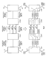
- FIGS. 6A-6C illustrate an example wherein three LSPs are setup between an LER I-HOP and an LER E-HOP, with two intermediate LSRs C-HOP 1 and C-HOP 2 .
- An actual LSP could be longer, or could have more LAG hops, and the network area will almost certainly contain more nodes, but a simplified view of the network area has been selected so that operation of an embodiment can be presented with clarity.
- C-HOP 1 and C-HOP 2 are connected by three point-to-point component links CL 1 , CL 2 , and CL 3 that are managed as a LAG and reported to IGP as a single logical link.
- C-HOP 1 created component link TE sub-TLVs as described above, however, and thus I-HOP is aware of the component link unreserved bandwidths.
- C-HOP 1 has reported unreserved bandwidths UBW of 100, 80, and 70, respectively, on CL 1 , CL 2 , and CL 3 .
- I-HOP formulates an explicit route request specifying FS 1 , BW 50 , and an explicit route C-HOP 2 /CL 1 , E-HOP, and forwards this request over RSVP-TE to C-HOP 1 .
- C-HOP 1 determines that sufficient bandwidth exists on CL 1 for the request, and thus forwards an RSVP-TE explicit route request FS 1 , BW 50 , explicit route E-HOP to C-HOP 2 (the path request itself need not traverse CL 1 , but could be placed on any LAG member).
- C-HOP 2 Assuming C-HOP 2 can grant the bandwidth requested, it forwards an RSVP-TE explicit route request FS 1 , BW 50 to E-HOP. E-HOP responds by returning to C-HOP 2 an RSVP-TE reservation request with a label T 3 .
- C-HOP 2 reserves the bandwidth on its link to E-HOP, and returns to C-HOP 1 an RSVP-TE reservation request with a label T 2 .
- C-HOP 1 reserves the bandwidth on CL 1 , reducing CL 1 's unreserved bandwidth from 100 to 50.
- C-HOP 1 returns to I-HOP an RSVP-TE reservation request with a label T 1 .
- the LSP for filterspec FS 1 is now ready for use.
- I-HOP labels the packet with an MPLS header specifying T 1 , and forwards the packet to C-HOP 1 .
- C-HOP 1 upon receiving the MPLS packet, looks up T 1 in its route table and determines that T 1 should be swapped for T 2 and the packet forwarded out the CL 1 interface to C-HOP 2 .
- C-HOP 2 upon receiving the MPLS packet, looks up T 2 in its route table and determines that T 3 should be swapped for T 2 and the packet forwarded to E-HOP.
- E-HOP removes the MPLS header and forwards FS 1 out an appropriate interface (EL 2 in this example).
- the designation “C-HOP 2 /CLS” represents a “component link specification” to C-HOP 2 .
- C-HOP 1 may set up the path using any of CL 1 , CL 2 , and CL 3 that can best meet bandwidth BW and whatever other constraints are specified in CLS (setup priority, hold priority, latency, average bandwidth, etc.).
- C-HOP 1 selects CL 2 , with UBW of 80, to fulfill this request. This results in an LSP that uses the labels T 4 -T 5 -T 6 , and reports UBWs on CL 1 , CL 2 , and CL 3 of 50, 50, and 70, respectively.
- I-HOP labels the packet with an MPLS header specifying T 4 , and forwards the packet to C-HOP 1 .
- C-HOP 1 upon receiving the MPLS packet, looks up T 4 in its route table and determines that T 5 should be swapped for T 4 and the packet forwarded out the CL 2 interface to C-HOP 2 .
- C-HOP 2 upon receiving the MPLS packet, looks up T 5 in its route table and determines that T 6 should be swapped for T 5 and the packet forwarded to E-HOP.
- E-HOP removes the MPLS header and forwards FS 2 out an appropriate interface (ELI in this example).
- C-HOP 2 indicates that C-HOP 1 is to use the LAG group CL 1 , CL 2 , CL 3 as a whole to form the downstream segment of the LSP. This results in an LSP that uses the labels T 7 -T 8 -T 9 , and reports UBWs on CL 1 , CL 2 , and CL 3 of 36, 36, and 56, respectively. Although this is an equal apportionment of the reservation bandwidth, the FS 3 traffic may not balance equally among the three links. Thus I-HOP 1 may select this reservation method for low-priority traffic that can be dropped/delayed if necessary.
- I-HOP labels the packet with an MPLS header specifying T 7 , and forwards the packet to C-HOP 1 .
- C-HOP 1 upon receiving the MPLS packet, looks up T 7 in its route table and determines that T 8 should be swapped for T 7 .
- C-HOP 1 hashes selected header information from FS 3 to select one of CL 1 , CL 2 , or CL 3 for forwarding the packet, in this case selecting CL 3 .
- Other packets in the filterspec FS 3 unless all have identical addressing information, will in some cases be hashed to CL 1 and CL 2 as well.
- CHOP- 2 upon receiving the MPLS packet, looks up T 8 in its route table and determines that T 9 should be swapped for T 8 and the packet forwarded to E-HOP.
- E-HOP removes the MPLS header and forwards FS 3 out an appropriate interface (EL 2 in this example).
- FIG. 7 illustrates, in block diagram form, a block diagram for ingress operations performed at C-HOP 2 in one embodiment and for the FIG. 6C scenario.
- Blocks illustrated in FIG. 7 include a lookup engine LE, a hash calculate function HC, a modulus function MOD, a LAG group table LGT, a routing table RT, and a packet processor PP.
- lookup engine LE When a packet P 1 arrives, its headers are inspected by lookup engine LE.
- Lookup engine LE forms several keys from the header contents, including a hash key and a CAM (Content-Addressable Memory) key.
- the hash key will typically use flow-stable information such as source and destination addresses and ports, Ethernet and/or IP packet type, etc., such that packets in a common flow will produce the same hash key.
- the CAM key formats header information in an ordering expected for routing lookups in a CAM containing RT. Such a format is highly implementation-specific, but is shown in FIG. 7 to include at least an Ethertype and either source and destination addresses (SA/DA) or an MPLS label.
- Routing table RT includes CAM entries corresponding to various possible CAM keys.
- a typical CAM is a ternary CAM, e.g., a lookup of any particular bit in the CAM key can either be required to match a 0, match a 1, or match either (a “don't care” condition, noted by an “X”).
- Routing table RT includes information linked to the CAM entries, either stored explicitly with the CAM entry or stored elsewhere in a memory location derivable from the address returned by a CAM hit. In FIG. 7 , this linked information includes a MI (Multiple Interface) flag, a field specifying either an outbound interface or a MI group ID, and packet edit instructions. The MI flag is set to 0 for an entry when the entry specifies an outbound interface, and is set to 1 when an entry specifies a MIF group ID.
- MI Multiple Interface
- routing table RT Four entries are shown in routing table RT.
- the first entry is for IP packets with destination addresses that match the address 192.168.X.X, where X matches anything.
- the routing table indicates that packets matching this entry are to be edited to update their time to live (TTL) and forwarded out a port P 2 on a line card LC 4 .
- TTL time to live
- routing table RT The other three entries shown in routing table RT are for the three MPLS flowspecs FS 1 , FS 2 , and FS 3 shown in FIG. 6C .
- Each entry matches a CAM key for an MPLS packet, with MPLS labels T 1 , T 4 , and T 7 , respectively, for the three entries.
- the routing table indicates that packets matching this entry are to be edited to update their TTL, and that T 2 is to be swapped for T 1 in the MPLS header.
- the packets are then forwarded out the outbound interface CL 1 on a linecard LC 3 .
- the routing table indicates that packets matching this entry are to be edited to update their TTL, and that T 5 is to be swapped for T 4 in the MPLS header.
- the packets are then forwarded out the outbound interface CL 2 on linecard LC 3 .
- the routing table indicates that packets matching this entry are to be edited to update their TTL, and that T 8 is to be swapped for T 7 in the MPLS header.
- the packets are then forwarded on the LAG group LL 5 .
- routing table RT indicates that an additional step is required to determine the outbound interface.
- a MI flag value of 1 causes the group ID to be used to address an entry in the LAG group table LGT.
- LGT entries indicate a number of interfaces in the group (#IF) and a list of the interfaces.
- the single entry shown is for LAG LL 5 , and specifies three interfaces CL 1 , CL 2 , and CL 3 as members.
- the #IF of 3 is supplied to the MOD function, which performs a modulus operation on the hash value produced by hash calculate HC, and thus returns either 0, 1, or 2.
- the result of the modulus operation is provided as a selector into the IF list, in this case selecting the third entry for the outbound interface.
- a small internal use header specifying the outbound interface is prepended to the packet as modified by the packet processor, forming a modified packet P 1 ′.
- the internal use header will be removed before the packet leaves the specified outbound interface.
- the preceding example illustrates one method for using hardware to forward traffic-engineered MPLS packets over either a LAG or a component link of the LAG.
- the component link be a single physical link.
- a traffic-engineered component link could also be a subset of the LAG component links, i.e., LGT could contain a second entry specifying two interfaces (CL 1 and CL 2 , for example), with some routing table entries pointing to this LGT entry.
- LACP continues to manage CL 1 , CL 2 , and CL 3 as a single LAG, nothing prevents MPLE-TE in this example from managing a subset of the LAG membership from a traffic engineering standpoint and assigning some traffic to the subset.
- Some LAG component links can be dedicated to serve individual LSPs, with no traffic hashed to those links. Likewise, some LAG component links can be dedicated only to general LAG treatment, by not advertising component link bandwidth for those links. Also, when a component link carries both individual LSPs and hashed traffic, the hashed traffic can be rate-limited to guarantee the bandwidth reserved for the individual LSPs assigned to that link.
- a management processor (or group of cooperating processors) will be responsible for interpreting and creating IGP LSAs and RSVP-TE messages, managing reservations for links and component links, and updating the routing tables as necessary.
- Such functions will generally be expressed as machine-executable software stored on a computer-readable medium, with the medium being local and/or remote to the processor(s) executing the software.
Abstract
Description
Claims (16)
Priority Applications (1)
| Application Number | Priority Date | Filing Date | Title |
|---|---|---|---|
| US12/080,748 US7903554B1 (en) | 2008-04-04 | 2008-04-04 | Leaking component link traffic engineering information |
Applications Claiming Priority (1)
| Application Number | Priority Date | Filing Date | Title |
|---|---|---|---|
| US12/080,748 US7903554B1 (en) | 2008-04-04 | 2008-04-04 | Leaking component link traffic engineering information |
Publications (1)
| Publication Number | Publication Date |
|---|---|
| US7903554B1 true US7903554B1 (en) | 2011-03-08 |
Family
ID=43639326
Family Applications (1)
| Application Number | Title | Priority Date | Filing Date |
|---|---|---|---|
| US12/080,748 Active 2028-11-13 US7903554B1 (en) | 2008-04-04 | 2008-04-04 | Leaking component link traffic engineering information |
Country Status (1)
| Country | Link |
|---|---|
| US (1) | US7903554B1 (en) |
Cited By (64)
| Publication number | Priority date | Publication date | Assignee | Title |
|---|---|---|---|---|
| US20060167838A1 (en) * | 2005-01-21 | 2006-07-27 | Z-Force Communications, Inc. | File-based hybrid file storage scheme supporting multiple file switches |
| US20110153829A1 (en) * | 2009-12-21 | 2011-06-23 | Electronics And Telecommunications Research Institute | Traffic engineering database control system and method for guaranteeing accuracy of traffic engineering database |
| US20110205909A1 (en) * | 2008-10-23 | 2011-08-25 | Huawei Technologies Co., Ltd. | Method, node and system for obtaining link aggregation group information |
| US20110268115A1 (en) * | 2010-04-29 | 2011-11-03 | Juniper Networks, Inc. | Multicast over lag and irb in a routing device |
| US20120036279A1 (en) * | 2010-08-09 | 2012-02-09 | Cisco Technology, Inc. | Distributed connectivity verification protocol redundancy |
| WO2013152240A1 (en) * | 2012-04-04 | 2013-10-10 | Alcatel-Lucent Usa Inc. | System and method for data plane fate separation of label distribution protocol (ldp) label switched paths (lsps) |
| US20130329602A1 (en) * | 2011-02-17 | 2013-12-12 | Huawei Technologies Co., Ltd. | Method, node device and system for establishing label switched path |
| US8682916B2 (en) | 2007-05-25 | 2014-03-25 | F5 Networks, Inc. | Remote file virtualization in a switched file system |
| US20140313880A1 (en) * | 2010-09-29 | 2014-10-23 | Telefonaktiebolaget L.M. Ericsson (Publ) | Fast flooding based fast convergence to recover from network failures |
| US8879431B2 (en) | 2011-05-16 | 2014-11-04 | F5 Networks, Inc. | Method for load balancing of requests' processing of diameter servers |
| US9020912B1 (en) | 2012-02-20 | 2015-04-28 | F5 Networks, Inc. | Methods for accessing data in a compressed file system and devices thereof |
| US9143451B2 (en) | 2007-10-01 | 2015-09-22 | F5 Networks, Inc. | Application layer network traffic prioritization |
| US9195500B1 (en) | 2010-02-09 | 2015-11-24 | F5 Networks, Inc. | Methods for seamless storage importing and devices thereof |
| US9244843B1 (en) | 2012-02-20 | 2016-01-26 | F5 Networks, Inc. | Methods for improving flow cache bandwidth utilization and devices thereof |
| WO2016033785A1 (en) * | 2014-09-04 | 2016-03-10 | 华为技术有限公司 | Method for synchronizing forwarding tables, network device, and system |
| WO2016036305A1 (en) * | 2014-09-05 | 2016-03-10 | Telefonaktiebolaget L M Ericsson (Publ) | Explicit control of aggregation links via is-is |
| US9286298B1 (en) | 2010-10-14 | 2016-03-15 | F5 Networks, Inc. | Methods for enhancing management of backup data sets and devices thereof |
| US20160173363A1 (en) * | 2013-10-01 | 2016-06-16 | Juniper Networks, Inc. | Dynamic area filtering for link-state routing protocols |
| US9420049B1 (en) | 2010-06-30 | 2016-08-16 | F5 Networks, Inc. | Client side human user indicator |
| US20160330109A1 (en) * | 2015-05-08 | 2016-11-10 | Oracle International Corporation | Triggered-actions network processor |
| US9497614B1 (en) | 2013-02-28 | 2016-11-15 | F5 Networks, Inc. | National traffic steering device for a better control of a specific wireless/LTE network |
| US9503375B1 (en) * | 2010-06-30 | 2016-11-22 | F5 Networks, Inc. | Methods for managing traffic in a multi-service environment and devices thereof |
| US20160344607A1 (en) * | 2015-05-21 | 2016-11-24 | Huawei Technologies Co., Ltd. | Transport Software Defined Networking (SDN) - Zero Configuration Adjacency via Packet Snooping |
| US20160344652A1 (en) * | 2015-05-21 | 2016-11-24 | Huawei Technologies Co., Ltd. | Transport Software Defined Networking (SDN) -Logical Link Aggregation (LAG) Member Signaling |
| US9519501B1 (en) | 2012-09-30 | 2016-12-13 | F5 Networks, Inc. | Hardware assisted flow acceleration and L2 SMAC management in a heterogeneous distributed multi-tenant virtualized clustered system |
| US9554418B1 (en) | 2013-02-28 | 2017-01-24 | F5 Networks, Inc. | Device for topology hiding of a visited network |
| US9578090B1 (en) | 2012-11-07 | 2017-02-21 | F5 Networks, Inc. | Methods for provisioning application delivery service and devices thereof |
| US9590897B1 (en) * | 2015-02-26 | 2017-03-07 | Qlogic Corporation | Methods and systems for network devices and associated network transmissions |
| US20170230294A1 (en) * | 2016-02-04 | 2017-08-10 | Ciena Corporation | Port congestion resiliency in a multi-card and multi-switch link aggregation group |
| US9860350B2 (en) | 2015-05-12 | 2018-01-02 | Huawei Technologies Co., Ltd. | Transport software defined networking (SDN)—logical to physical topology discovery |
| US20180083871A1 (en) * | 2012-10-05 | 2018-03-22 | Cisco Technology, Inc. | Segment routing techniques |
| US10033837B1 (en) | 2012-09-29 | 2018-07-24 | F5 Networks, Inc. | System and method for utilizing a data reducing module for dictionary compression of encoded data |
| US10097616B2 (en) | 2012-04-27 | 2018-10-09 | F5 Networks, Inc. | Methods for optimizing service of content requests and devices thereof |
| US10182013B1 (en) | 2014-12-01 | 2019-01-15 | F5 Networks, Inc. | Methods for managing progressive image delivery and devices thereof |
| US10187317B1 (en) | 2013-11-15 | 2019-01-22 | F5 Networks, Inc. | Methods for traffic rate control and devices thereof |
| US10230566B1 (en) | 2012-02-17 | 2019-03-12 | F5 Networks, Inc. | Methods for dynamically constructing a service principal name and devices thereof |
| US10375155B1 (en) | 2013-02-19 | 2019-08-06 | F5 Networks, Inc. | System and method for achieving hardware acceleration for asymmetric flow connections |
| WO2019152247A1 (en) * | 2018-02-05 | 2019-08-08 | Ciena Corporation | Segment routing traffic engineering based on link utilization |
| US10404698B1 (en) | 2016-01-15 | 2019-09-03 | F5 Networks, Inc. | Methods for adaptive organization of web application access points in webtops and devices thereof |
| US10412198B1 (en) | 2016-10-27 | 2019-09-10 | F5 Networks, Inc. | Methods for improved transmission control protocol (TCP) performance visibility and devices thereof |
| WO2019220425A1 (en) * | 2018-05-12 | 2019-11-21 | Drivenets Ltd. | A device and a system for ospf cost metrics mirroring |
| US10505818B1 (en) | 2015-05-05 | 2019-12-10 | F5 Networks. Inc. | Methods for analyzing and load balancing based on server health and devices thereof |
| US10505792B1 (en) | 2016-11-02 | 2019-12-10 | F5 Networks, Inc. | Methods for facilitating network traffic analytics and devices thereof |
| US10601707B2 (en) | 2014-07-17 | 2020-03-24 | Cisco Technology, Inc. | Segment routing using a remote forwarding adjacency identifier |
| US10693765B2 (en) | 2015-02-26 | 2020-06-23 | Cisco Technology, Inc. | Failure protection for traffic-engineered bit indexed explicit replication |
| US10721269B1 (en) | 2009-11-06 | 2020-07-21 | F5 Networks, Inc. | Methods and system for returning requests with javascript for clients before passing a request to a server |
| US10742537B2 (en) | 2016-05-26 | 2020-08-11 | Cisco Technology, Inc. | Enforcing strict shortest path forwarding using strict segment identifiers |
| US10764146B2 (en) | 2013-03-15 | 2020-09-01 | Cisco Technology, Inc. | Segment routing over label distribution protocol |
| US10812266B1 (en) | 2017-03-17 | 2020-10-20 | F5 Networks, Inc. | Methods for managing security tokens based on security violations and devices thereof |
| US10834065B1 (en) | 2015-03-31 | 2020-11-10 | F5 Networks, Inc. | Methods for SSL protected NTLM re-authentication and devices thereof |
| US20210112004A1 (en) * | 2019-10-15 | 2021-04-15 | Electronics And Telecommunications Research Institute | Apparatus and method for forwarding a packet in content centric network |
| US11032197B2 (en) | 2016-09-15 | 2021-06-08 | Cisco Technology, Inc. | Reroute detection in segment routing data plane |
| US11063758B1 (en) | 2016-11-01 | 2021-07-13 | F5 Networks, Inc. | Methods for facilitating cipher selection and devices thereof |
| US11122042B1 (en) | 2017-05-12 | 2021-09-14 | F5 Networks, Inc. | Methods for dynamically managing user access control and devices thereof |
| US11178150B1 (en) | 2016-01-20 | 2021-11-16 | F5 Networks, Inc. | Methods for enforcing access control list based on managed application and devices thereof |
| US11223689B1 (en) | 2018-01-05 | 2022-01-11 | F5 Networks, Inc. | Methods for multipath transmission control protocol (MPTCP) based session migration and devices thereof |
| US11336574B2 (en) | 2014-03-06 | 2022-05-17 | Cisco Technology, Inc. | Segment routing extension headers |
| US11343237B1 (en) | 2017-05-12 | 2022-05-24 | F5, Inc. | Methods for managing a federated identity environment using security and access control data and devices thereof |
| US11350254B1 (en) | 2015-05-05 | 2022-05-31 | F5, Inc. | Methods for enforcing compliance policies and devices thereof |
| US11411866B1 (en) * | 2021-02-01 | 2022-08-09 | Juniper Networks, Inc. | Supporting multiple segment routing traffic engineering algorithms |
| US11722404B2 (en) | 2019-09-24 | 2023-08-08 | Cisco Technology, Inc. | Communicating packets across multi-domain networks using compact forwarding instructions |
| US11757946B1 (en) | 2015-12-22 | 2023-09-12 | F5, Inc. | Methods for analyzing network traffic and enforcing network policies and devices thereof |
| US11838851B1 (en) | 2014-07-15 | 2023-12-05 | F5, Inc. | Methods for managing L7 traffic classification and devices thereof |
| US11895138B1 (en) | 2015-02-02 | 2024-02-06 | F5, Inc. | Methods for improving web scanner accuracy and devices thereof |
Citations (7)
| Publication number | Priority date | Publication date | Assignee | Title |
|---|---|---|---|---|
| US20040114595A1 (en) * | 2001-04-19 | 2004-06-17 | Masami Doukai | Restoration and protection method and an apparatus thereof |
| US20060146696A1 (en) * | 2005-01-06 | 2006-07-06 | At&T Corp. | Bandwidth management for MPLS fast rerouting |
| US20080151783A1 (en) * | 2006-12-26 | 2008-06-26 | Fujitsu Limited | Communication apparatus and protocol processing method |
| US20080151756A1 (en) * | 2006-12-22 | 2008-06-26 | Jean-Philippe Vasseur | Optimization of distributed tunnel rerouting in a computer network with coordinated head-end node path computation |
| US20080253379A1 (en) * | 2000-01-11 | 2008-10-16 | Fujitsu Limited | Label switching system |
| US20080310442A1 (en) * | 2006-02-24 | 2008-12-18 | Huawei Technologies Co., Ltd. | Method And System For Performing Edge To Edge Pseudo Wire Emulation Of Bundling Interface |
| US20090182894A1 (en) * | 2008-01-11 | 2009-07-16 | Jean-Philippe Vasseur | Dynamic path computation element load balancing with backup path computation elements |
-
2008
- 2008-04-04 US US12/080,748 patent/US7903554B1/en active Active
Patent Citations (8)
| Publication number | Priority date | Publication date | Assignee | Title |
|---|---|---|---|---|
| US20080253379A1 (en) * | 2000-01-11 | 2008-10-16 | Fujitsu Limited | Label switching system |
| US20040114595A1 (en) * | 2001-04-19 | 2004-06-17 | Masami Doukai | Restoration and protection method and an apparatus thereof |
| US20060146696A1 (en) * | 2005-01-06 | 2006-07-06 | At&T Corp. | Bandwidth management for MPLS fast rerouting |
| US20080253281A1 (en) * | 2005-01-06 | 2008-10-16 | At&T Corporation | Bandwidth Management for MPLS Fast Rerouting |
| US20080310442A1 (en) * | 2006-02-24 | 2008-12-18 | Huawei Technologies Co., Ltd. | Method And System For Performing Edge To Edge Pseudo Wire Emulation Of Bundling Interface |
| US20080151756A1 (en) * | 2006-12-22 | 2008-06-26 | Jean-Philippe Vasseur | Optimization of distributed tunnel rerouting in a computer network with coordinated head-end node path computation |
| US20080151783A1 (en) * | 2006-12-26 | 2008-06-26 | Fujitsu Limited | Communication apparatus and protocol processing method |
| US20090182894A1 (en) * | 2008-01-11 | 2009-07-16 | Jean-Philippe Vasseur | Dynamic path computation element load balancing with backup path computation elements |
Cited By (104)
| Publication number | Priority date | Publication date | Assignee | Title |
|---|---|---|---|---|
| US20060167838A1 (en) * | 2005-01-21 | 2006-07-27 | Z-Force Communications, Inc. | File-based hybrid file storage scheme supporting multiple file switches |
| US8682916B2 (en) | 2007-05-25 | 2014-03-25 | F5 Networks, Inc. | Remote file virtualization in a switched file system |
| US9143451B2 (en) | 2007-10-01 | 2015-09-22 | F5 Networks, Inc. | Application layer network traffic prioritization |
| US20110205909A1 (en) * | 2008-10-23 | 2011-08-25 | Huawei Technologies Co., Ltd. | Method, node and system for obtaining link aggregation group information |
| US8559318B2 (en) * | 2008-10-23 | 2013-10-15 | Huawei Technologies Co., Ltd. | Method, node and system for obtaining link aggregation group information |
| US10721269B1 (en) | 2009-11-06 | 2020-07-21 | F5 Networks, Inc. | Methods and system for returning requests with javascript for clients before passing a request to a server |
| US11108815B1 (en) | 2009-11-06 | 2021-08-31 | F5 Networks, Inc. | Methods and system for returning requests with javascript for clients before passing a request to a server |
| US20110153829A1 (en) * | 2009-12-21 | 2011-06-23 | Electronics And Telecommunications Research Institute | Traffic engineering database control system and method for guaranteeing accuracy of traffic engineering database |
| US9195500B1 (en) | 2010-02-09 | 2015-11-24 | F5 Networks, Inc. | Methods for seamless storage importing and devices thereof |
| US20110268115A1 (en) * | 2010-04-29 | 2011-11-03 | Juniper Networks, Inc. | Multicast over lag and irb in a routing device |
| US8699485B2 (en) * | 2010-04-29 | 2014-04-15 | Juniper Networks, Inc. | Multicast over lag and IRB in a routing device |
| US9420049B1 (en) | 2010-06-30 | 2016-08-16 | F5 Networks, Inc. | Client side human user indicator |
| US9503375B1 (en) * | 2010-06-30 | 2016-11-22 | F5 Networks, Inc. | Methods for managing traffic in a multi-service environment and devices thereof |
| US8850062B2 (en) * | 2010-08-09 | 2014-09-30 | Cisco Technology, Inc. | Distributed connectivity verification protocol redundancy |
| US20120036279A1 (en) * | 2010-08-09 | 2012-02-09 | Cisco Technology, Inc. | Distributed connectivity verification protocol redundancy |
| US20140313880A1 (en) * | 2010-09-29 | 2014-10-23 | Telefonaktiebolaget L.M. Ericsson (Publ) | Fast flooding based fast convergence to recover from network failures |
| US9614721B2 (en) * | 2010-09-29 | 2017-04-04 | Telefonaktiebolaget L M Ericsson (Publ) | Fast flooding based fast convergence to recover from network failures |
| US9286298B1 (en) | 2010-10-14 | 2016-03-15 | F5 Networks, Inc. | Methods for enhancing management of backup data sets and devices thereof |
| US9755905B2 (en) * | 2011-02-17 | 2017-09-05 | Huawei Technologies Co., Ltd. | Method, node device and system for establishing label switched path |
| US9258189B2 (en) * | 2011-02-17 | 2016-02-09 | Huawei Technologies Co., Ltd. | Method, node device and system for establishing label switched path |
| US20170339019A1 (en) * | 2011-02-17 | 2017-11-23 | Huawei Technologies Co., Ltd. | Method, node device and system for establishing label switched path |
| US10084655B2 (en) * | 2011-02-17 | 2018-09-25 | Huawei Technologies Co., Ltd. | Method, node device and system for establishing label switched path |
| US20130329602A1 (en) * | 2011-02-17 | 2013-12-12 | Huawei Technologies Co., Ltd. | Method, node device and system for establishing label switched path |
| US9356998B2 (en) | 2011-05-16 | 2016-05-31 | F5 Networks, Inc. | Method for load balancing of requests' processing of diameter servers |
| US8879431B2 (en) | 2011-05-16 | 2014-11-04 | F5 Networks, Inc. | Method for load balancing of requests' processing of diameter servers |
| US10230566B1 (en) | 2012-02-17 | 2019-03-12 | F5 Networks, Inc. | Methods for dynamically constructing a service principal name and devices thereof |
| USRE48725E1 (en) | 2012-02-20 | 2021-09-07 | F5 Networks, Inc. | Methods for accessing data in a compressed file system and devices thereof |
| US9244843B1 (en) | 2012-02-20 | 2016-01-26 | F5 Networks, Inc. | Methods for improving flow cache bandwidth utilization and devices thereof |
| US9020912B1 (en) | 2012-02-20 | 2015-04-28 | F5 Networks, Inc. | Methods for accessing data in a compressed file system and devices thereof |
| CN104322024A (en) * | 2012-04-04 | 2015-01-28 | 阿尔卡特朗讯公司 | System and method for data plane fate separation of label distribution protocol (LDP) label switched paths (LSPs) |
| WO2013152240A1 (en) * | 2012-04-04 | 2013-10-10 | Alcatel-Lucent Usa Inc. | System and method for data plane fate separation of label distribution protocol (ldp) label switched paths (lsps) |
| JP2015515828A (en) * | 2012-04-04 | 2015-05-28 | アルカテル−ルーセント | System and method for data plane fate separation of label distribution protocol (LDP) label switched path (LSP) |
| CN104380673A (en) * | 2012-04-04 | 2015-02-25 | 阿尔卡特朗讯公司 | System and method for using label distribution protocol (LDP) in IPv6 networks |
| US9225649B2 (en) | 2012-04-04 | 2015-12-29 | Alcatel Lucent | System and method for data plane fate separation of label distribution protocol (LDP) label switched paths (LSPs) |
| US10097616B2 (en) | 2012-04-27 | 2018-10-09 | F5 Networks, Inc. | Methods for optimizing service of content requests and devices thereof |
| US10033837B1 (en) | 2012-09-29 | 2018-07-24 | F5 Networks, Inc. | System and method for utilizing a data reducing module for dictionary compression of encoded data |
| US9519501B1 (en) | 2012-09-30 | 2016-12-13 | F5 Networks, Inc. | Hardware assisted flow acceleration and L2 SMAC management in a heterogeneous distributed multi-tenant virtualized clustered system |
| US10469370B2 (en) * | 2012-10-05 | 2019-11-05 | Cisco Technology, Inc. | Segment routing techniques |
| US20180083871A1 (en) * | 2012-10-05 | 2018-03-22 | Cisco Technology, Inc. | Segment routing techniques |
| US9578090B1 (en) | 2012-11-07 | 2017-02-21 | F5 Networks, Inc. | Methods for provisioning application delivery service and devices thereof |
| US10375155B1 (en) | 2013-02-19 | 2019-08-06 | F5 Networks, Inc. | System and method for achieving hardware acceleration for asymmetric flow connections |
| US9554418B1 (en) | 2013-02-28 | 2017-01-24 | F5 Networks, Inc. | Device for topology hiding of a visited network |
| US9497614B1 (en) | 2013-02-28 | 2016-11-15 | F5 Networks, Inc. | National traffic steering device for a better control of a specific wireless/LTE network |
| US11784889B2 (en) | 2013-03-15 | 2023-10-10 | Cisco Technology, Inc. | Segment routing over label distribution protocol |
| US11290340B2 (en) | 2013-03-15 | 2022-03-29 | Cisco Technology, Inc. | Segment routing over label distribution protocol |
| US10764146B2 (en) | 2013-03-15 | 2020-09-01 | Cisco Technology, Inc. | Segment routing over label distribution protocol |
| US11689427B2 (en) | 2013-03-15 | 2023-06-27 | Cisco Technology, Inc. | Segment routing over label distribution protocol |
| US11424987B2 (en) | 2013-03-15 | 2022-08-23 | Cisco Technology, Inc. | Segment routing: PCE driven dynamic setup of forwarding adjacencies and explicit path |
| US10097446B2 (en) * | 2013-10-01 | 2018-10-09 | Juniper Networks, Inc. | Dynamic area filtering for link-state routing protocols |
| US20160173363A1 (en) * | 2013-10-01 | 2016-06-16 | Juniper Networks, Inc. | Dynamic area filtering for link-state routing protocols |
| US10187317B1 (en) | 2013-11-15 | 2019-01-22 | F5 Networks, Inc. | Methods for traffic rate control and devices thereof |
| US11336574B2 (en) | 2014-03-06 | 2022-05-17 | Cisco Technology, Inc. | Segment routing extension headers |
| US11374863B2 (en) | 2014-03-06 | 2022-06-28 | Cisco Technology, Inc. | Segment routing extension headers |
| US11838851B1 (en) | 2014-07-15 | 2023-12-05 | F5, Inc. | Methods for managing L7 traffic classification and devices thereof |
| US10601707B2 (en) | 2014-07-17 | 2020-03-24 | Cisco Technology, Inc. | Segment routing using a remote forwarding adjacency identifier |
| US10079781B2 (en) | 2014-09-04 | 2018-09-18 | Huawei Technologies Co., Ltd. | Forwarding table synchronization method, network device, and system |
| WO2016033785A1 (en) * | 2014-09-04 | 2016-03-10 | 华为技术有限公司 | Method for synchronizing forwarding tables, network device, and system |
| US10164872B2 (en) * | 2014-09-05 | 2018-12-25 | Telefonaktiebolaget Lm Ericsson (Publ) | Explicit control of aggregation links via IS-IS |
| WO2016036305A1 (en) * | 2014-09-05 | 2016-03-10 | Telefonaktiebolaget L M Ericsson (Publ) | Explicit control of aggregation links via is-is |
| US20190081888A1 (en) * | 2014-09-05 | 2019-03-14 | Telefonaktiebolaget Lm Ericsson (Publ) | Explicit control of aggregation links via is-is |
| US10868756B2 (en) * | 2014-09-05 | 2020-12-15 | Telefonaktiebolaget Lm Ericsson (Publ) | Explicit control of aggregation links via IS-IS |
| US10182013B1 (en) | 2014-12-01 | 2019-01-15 | F5 Networks, Inc. | Methods for managing progressive image delivery and devices thereof |
| US11895138B1 (en) | 2015-02-02 | 2024-02-06 | F5, Inc. | Methods for improving web scanner accuracy and devices thereof |
| US9590897B1 (en) * | 2015-02-26 | 2017-03-07 | Qlogic Corporation | Methods and systems for network devices and associated network transmissions |
| US10693765B2 (en) | 2015-02-26 | 2020-06-23 | Cisco Technology, Inc. | Failure protection for traffic-engineered bit indexed explicit replication |
| US10958566B2 (en) | 2015-02-26 | 2021-03-23 | Cisco Technology, Inc. | Traffic engineering for bit indexed explicit replication |
| US10834065B1 (en) | 2015-03-31 | 2020-11-10 | F5 Networks, Inc. | Methods for SSL protected NTLM re-authentication and devices thereof |
| US10505818B1 (en) | 2015-05-05 | 2019-12-10 | F5 Networks. Inc. | Methods for analyzing and load balancing based on server health and devices thereof |
| US11350254B1 (en) | 2015-05-05 | 2022-05-31 | F5, Inc. | Methods for enforcing compliance policies and devices thereof |
| US20160330109A1 (en) * | 2015-05-08 | 2016-11-10 | Oracle International Corporation | Triggered-actions network processor |
| US10193797B2 (en) * | 2015-05-08 | 2019-01-29 | Oracle International Corporation | Triggered-actions network processor |
| US9860350B2 (en) | 2015-05-12 | 2018-01-02 | Huawei Technologies Co., Ltd. | Transport software defined networking (SDN)—logical to physical topology discovery |
| US20160344607A1 (en) * | 2015-05-21 | 2016-11-24 | Huawei Technologies Co., Ltd. | Transport Software Defined Networking (SDN) - Zero Configuration Adjacency via Packet Snooping |
| US20160344652A1 (en) * | 2015-05-21 | 2016-11-24 | Huawei Technologies Co., Ltd. | Transport Software Defined Networking (SDN) -Logical Link Aggregation (LAG) Member Signaling |
| US10015053B2 (en) * | 2015-05-21 | 2018-07-03 | Huawei Technologies Co., Ltd. | Transport software defined networking (SDN)—logical link aggregation (LAG) member signaling |
| US10425319B2 (en) * | 2015-05-21 | 2019-09-24 | Huawei Technologies Co., Ltd. | Transport software defined networking (SDN)—zero configuration adjacency via packet snooping |
| US11757946B1 (en) | 2015-12-22 | 2023-09-12 | F5, Inc. | Methods for analyzing network traffic and enforcing network policies and devices thereof |
| US10404698B1 (en) | 2016-01-15 | 2019-09-03 | F5 Networks, Inc. | Methods for adaptive organization of web application access points in webtops and devices thereof |
| US11178150B1 (en) | 2016-01-20 | 2021-11-16 | F5 Networks, Inc. | Methods for enforcing access control list based on managed application and devices thereof |
| US20170230294A1 (en) * | 2016-02-04 | 2017-08-10 | Ciena Corporation | Port congestion resiliency in a multi-card and multi-switch link aggregation group |
| US10171358B2 (en) * | 2016-02-04 | 2019-01-01 | Ciena Corporation | Port congestion resiliency in a multi-card and multi-switch link aggregation group |
| US11489756B2 (en) | 2016-05-26 | 2022-11-01 | Cisco Technology, Inc. | Enforcing strict shortest path forwarding using strict segment identifiers |
| US10742537B2 (en) | 2016-05-26 | 2020-08-11 | Cisco Technology, Inc. | Enforcing strict shortest path forwarding using strict segment identifiers |
| US11323356B2 (en) | 2016-05-26 | 2022-05-03 | Cisco Technology, Inc. | Enforcing strict shortest path forwarding using strict segment identifiers |
| US11671346B2 (en) | 2016-05-26 | 2023-06-06 | Cisco Technology, Inc. | Enforcing strict shortest path forwarding using strict segment identifiers |
| US11032197B2 (en) | 2016-09-15 | 2021-06-08 | Cisco Technology, Inc. | Reroute detection in segment routing data plane |
| US10412198B1 (en) | 2016-10-27 | 2019-09-10 | F5 Networks, Inc. | Methods for improved transmission control protocol (TCP) performance visibility and devices thereof |
| US11063758B1 (en) | 2016-11-01 | 2021-07-13 | F5 Networks, Inc. | Methods for facilitating cipher selection and devices thereof |
| US10505792B1 (en) | 2016-11-02 | 2019-12-10 | F5 Networks, Inc. | Methods for facilitating network traffic analytics and devices thereof |
| US10812266B1 (en) | 2017-03-17 | 2020-10-20 | F5 Networks, Inc. | Methods for managing security tokens based on security violations and devices thereof |
| US11122042B1 (en) | 2017-05-12 | 2021-09-14 | F5 Networks, Inc. | Methods for dynamically managing user access control and devices thereof |
| US11343237B1 (en) | 2017-05-12 | 2022-05-24 | F5, Inc. | Methods for managing a federated identity environment using security and access control data and devices thereof |
| US11223689B1 (en) | 2018-01-05 | 2022-01-11 | F5 Networks, Inc. | Methods for multipath transmission control protocol (MPTCP) based session migration and devices thereof |
| WO2019152247A1 (en) * | 2018-02-05 | 2019-08-08 | Ciena Corporation | Segment routing traffic engineering based on link utilization |
| US11909645B2 (en) | 2018-02-05 | 2024-02-20 | Ciena Corporation | Segment routing traffic engineering based on link utilization |
| CN111684768B (en) * | 2018-02-05 | 2022-11-25 | 希尔纳公司 | Segmented routing traffic engineering based on link utilization |
| US10541923B2 (en) | 2018-02-05 | 2020-01-21 | Ciena Corporation | Segment routing traffic engineering based on link utilization |
| CN111684768A (en) * | 2018-02-05 | 2020-09-18 | 希尔纳公司 | Segmented routing traffic engineering based on link utilization |
| WO2019220425A1 (en) * | 2018-05-12 | 2019-11-21 | Drivenets Ltd. | A device and a system for ospf cost metrics mirroring |
| US11627069B2 (en) | 2018-05-12 | 2023-04-11 | Drivenets Ltd. | Device and a system for OSPF cost metrics mirroring |
| US11722404B2 (en) | 2019-09-24 | 2023-08-08 | Cisco Technology, Inc. | Communicating packets across multi-domain networks using compact forwarding instructions |
| US11855884B2 (en) | 2019-09-24 | 2023-12-26 | Cisco Technology, Inc. | Communicating packets across multi-domain networks using compact forwarding instructions |
| US20210112004A1 (en) * | 2019-10-15 | 2021-04-15 | Electronics And Telecommunications Research Institute | Apparatus and method for forwarding a packet in content centric network |
| US11411866B1 (en) * | 2021-02-01 | 2022-08-09 | Juniper Networks, Inc. | Supporting multiple segment routing traffic engineering algorithms |
Similar Documents
| Publication | Publication Date | Title |
|---|---|---|
| US7903554B1 (en) | Leaking component link traffic engineering information | |
| US11606255B2 (en) | Method and apparatus for creating network slices | |
| CN109257278B (en) | Segmented routing label switched path method for non-segmented routing enabled routers | |
| US10193801B2 (en) | Automatic traffic mapping for multi-protocol label switching networks | |
| US7522603B2 (en) | Technique for efficiently routing IP traffic on CE-CE paths across a provider network | |
| US10637768B1 (en) | Enabling non-flexible-algorithm routers to participate in flexible-algorithm routing protocols | |
| US8325706B2 (en) | Hierarchical segmented label switched paths | |
| Sgambelluri et al. | Experimental demonstration of segment routing | |
| US11743166B2 (en) | Provisioning non-colored segment routing label switched paths via segment routing policies in border gateway protocol | |
| CN110650090B (en) | Routing method and router | |
| US10110479B1 (en) | Computing paths with ordered abstract hops | |
| US10630581B2 (en) | Dynamic tunnel report for path computation and traffic engineering within a computer network | |
| US11516114B2 (en) | Bandwidth constraint for multipath segment routing | |
| US11695688B2 (en) | Computing segment identifier lists for multipaths in a segment routing-enabled network | |
| US11425056B1 (en) | Dynamic computation of SR-TE policy for SR-enabled devices connected over non-SR-enabled devices | |
| US20070140233A1 (en) | Resource sharing among network | |
| US10554543B1 (en) | Migrating data traffic between label switched paths (LSPs) based on per-LSP protocol priority value | |
| US7702810B1 (en) | Detecting a label-switched path outage using adjacency information | |
| US11824763B2 (en) | Filtering topologies for path computation in massively scaled networks | |
| Martínez et al. | Experimental validation/evaluation of a GMPLS unified control plane in multi-layer (MPLS-TP/WSON) networks | |
| RU2803648C2 (en) | System and method for traffic routing in mpls network | |
| JP2022538527A (en) | Method and apparatus for routing traffic along IGP shortcut paths |
Legal Events
| Date | Code | Title | Description |
|---|---|---|---|
| AS | Assignment |
Owner name: FORCE10 NETWORKS, INC., CALIFORNIA Free format text: ASSIGNMENT OF ASSIGNORS INTEREST;ASSIGNORS:MANUR, RAJEEV;SUBRAMANIAN, KRISHNAMURTHY;ZINJUVADIA, VISHAL;SIGNING DATES FROM 20080401 TO 20080402;REEL/FRAME:021825/0192 |
|
| STCF | Information on status: patent grant |
Free format text: PATENTED CASE |
|
| AS | Assignment |
Owner name: BANK OF AMERICA, N.A., AS COLLATERAL AGENT, NORTH Free format text: PATENT SECURITY AGREEMENT (TERM LOAN);ASSIGNORS:DELL INC.;APPASSURE SOFTWARE, INC.;ASAP SOFTWARE EXPRESS, INC.;AND OTHERS;REEL/FRAME:031899/0261 Effective date: 20131029 Owner name: BANK OF AMERICA, N.A., AS ADMINISTRATIVE AGENT, TEXAS Free format text: PATENT SECURITY AGREEMENT (ABL);ASSIGNORS:DELL INC.;APPASSURE SOFTWARE, INC.;ASAP SOFTWARE EXPRESS, INC.;AND OTHERS;REEL/FRAME:031898/0001 Effective date: 20131029 Owner name: BANK OF NEW YORK MELLON TRUST COMPANY, N.A., AS FIRST LIEN COLLATERAL AGENT, TEXAS Free format text: PATENT SECURITY AGREEMENT (NOTES);ASSIGNORS:APPASSURE SOFTWARE, INC.;ASAP SOFTWARE EXPRESS, INC.;BOOMI, INC.;AND OTHERS;REEL/FRAME:031897/0348 Effective date: 20131029 Owner name: BANK OF AMERICA, N.A., AS COLLATERAL AGENT, NORTH CAROLINA Free format text: PATENT SECURITY AGREEMENT (TERM LOAN);ASSIGNORS:DELL INC.;APPASSURE SOFTWARE, INC.;ASAP SOFTWARE EXPRESS, INC.;AND OTHERS;REEL/FRAME:031899/0261 Effective date: 20131029 Owner name: BANK OF NEW YORK MELLON TRUST COMPANY, N.A., AS FI Free format text: PATENT SECURITY AGREEMENT (NOTES);ASSIGNORS:APPASSURE SOFTWARE, INC.;ASAP SOFTWARE EXPRESS, INC.;BOOMI, INC.;AND OTHERS;REEL/FRAME:031897/0348 Effective date: 20131029 Owner name: BANK OF AMERICA, N.A., AS ADMINISTRATIVE AGENT, TE Free format text: PATENT SECURITY AGREEMENT (ABL);ASSIGNORS:DELL INC.;APPASSURE SOFTWARE, INC.;ASAP SOFTWARE EXPRESS, INC.;AND OTHERS;REEL/FRAME:031898/0001 Effective date: 20131029 |
|
| FPAY | Fee payment |
Year of fee payment: 4 |
|
| AS | Assignment |
Owner name: DELL MARKETING L.P., TEXAS Free format text: RELEASE BY SECURED PARTY;ASSIGNOR:BANK OF AMERICA, N.A., AS ADMINISTRATIVE AGENT;REEL/FRAME:040065/0216 Effective date: 20160907 Owner name: WYSE TECHNOLOGY L.L.C., CALIFORNIA Free format text: RELEASE BY SECURED PARTY;ASSIGNOR:BANK OF AMERICA, N.A., AS ADMINISTRATIVE AGENT;REEL/FRAME:040065/0216 Effective date: 20160907 Owner name: ASAP SOFTWARE EXPRESS, INC., ILLINOIS Free format text: RELEASE BY SECURED PARTY;ASSIGNOR:BANK OF AMERICA, N.A., AS ADMINISTRATIVE AGENT;REEL/FRAME:040065/0216 Effective date: 20160907 Owner name: SECUREWORKS, INC., GEORGIA Free format text: RELEASE BY SECURED PARTY;ASSIGNOR:BANK OF AMERICA, N.A., AS ADMINISTRATIVE AGENT;REEL/FRAME:040065/0216 Effective date: 20160907 Owner name: DELL INC., TEXAS Free format text: RELEASE BY SECURED PARTY;ASSIGNOR:BANK OF AMERICA, N.A., AS ADMINISTRATIVE AGENT;REEL/FRAME:040065/0216 Effective date: 20160907 Owner name: DELL PRODUCTS L.P., TEXAS Free format text: RELEASE BY SECURED PARTY;ASSIGNOR:BANK OF AMERICA, N.A., AS ADMINISTRATIVE AGENT;REEL/FRAME:040065/0216 Effective date: 20160907 Owner name: FORCE10 NETWORKS, INC., CALIFORNIA Free format text: RELEASE BY SECURED PARTY;ASSIGNOR:BANK OF AMERICA, N.A., AS ADMINISTRATIVE AGENT;REEL/FRAME:040065/0216 Effective date: 20160907 Owner name: CREDANT TECHNOLOGIES, INC., TEXAS Free format text: RELEASE BY SECURED PARTY;ASSIGNOR:BANK OF AMERICA, N.A., AS ADMINISTRATIVE AGENT;REEL/FRAME:040065/0216 Effective date: 20160907 Owner name: COMPELLANT TECHNOLOGIES, INC., MINNESOTA Free format text: RELEASE BY SECURED PARTY;ASSIGNOR:BANK OF AMERICA, N.A., AS ADMINISTRATIVE AGENT;REEL/FRAME:040065/0216 Effective date: 20160907 Owner name: APPASSURE SOFTWARE, INC., VIRGINIA Free format text: RELEASE BY SECURED PARTY;ASSIGNOR:BANK OF AMERICA, N.A., AS ADMINISTRATIVE AGENT;REEL/FRAME:040065/0216 Effective date: 20160907 Owner name: PEROT SYSTEMS CORPORATION, TEXAS Free format text: RELEASE BY SECURED PARTY;ASSIGNOR:BANK OF AMERICA, N.A., AS ADMINISTRATIVE AGENT;REEL/FRAME:040065/0216 Effective date: 20160907 Owner name: DELL SOFTWARE INC., CALIFORNIA Free format text: RELEASE BY SECURED PARTY;ASSIGNOR:BANK OF AMERICA, N.A., AS ADMINISTRATIVE AGENT;REEL/FRAME:040065/0216 Effective date: 20160907 Owner name: DELL USA L.P., TEXAS Free format text: RELEASE BY SECURED PARTY;ASSIGNOR:BANK OF AMERICA, N.A., AS ADMINISTRATIVE AGENT;REEL/FRAME:040065/0216 Effective date: 20160907 |
|
| AS | Assignment |
Owner name: COMPELLENT TECHNOLOGIES, INC., MINNESOTA Free format text: RELEASE BY SECURED PARTY;ASSIGNOR:BANK OF AMERICA, N.A., AS COLLATERAL AGENT;REEL/FRAME:040040/0001 Effective date: 20160907 Owner name: APPASSURE SOFTWARE, INC., VIRGINIA Free format text: RELEASE BY SECURED PARTY;ASSIGNOR:BANK OF AMERICA, N.A., AS COLLATERAL AGENT;REEL/FRAME:040040/0001 Effective date: 20160907 Owner name: WYSE TECHNOLOGY L.L.C., CALIFORNIA Free format text: RELEASE BY SECURED PARTY;ASSIGNOR:BANK OF AMERICA, N.A., AS COLLATERAL AGENT;REEL/FRAME:040040/0001 Effective date: 20160907 Owner name: DELL USA L.P., TEXAS Free format text: RELEASE BY SECURED PARTY;ASSIGNOR:BANK OF AMERICA, N.A., AS COLLATERAL AGENT;REEL/FRAME:040040/0001 Effective date: 20160907 Owner name: DELL MARKETING L.P., TEXAS Free format text: RELEASE BY SECURED PARTY;ASSIGNOR:BANK OF AMERICA, N.A., AS COLLATERAL AGENT;REEL/FRAME:040040/0001 Effective date: 20160907 Owner name: SECUREWORKS, INC., GEORGIA Free format text: RELEASE BY SECURED PARTY;ASSIGNOR:BANK OF AMERICA, N.A., AS COLLATERAL AGENT;REEL/FRAME:040040/0001 Effective date: 20160907 Owner name: FORCE10 NETWORKS, INC., CALIFORNIA Free format text: RELEASE BY SECURED PARTY;ASSIGNOR:BANK OF AMERICA, N.A., AS COLLATERAL AGENT;REEL/FRAME:040040/0001 Effective date: 20160907 Owner name: DELL INC., TEXAS Free format text: RELEASE BY SECURED PARTY;ASSIGNOR:BANK OF AMERICA, N.A., AS COLLATERAL AGENT;REEL/FRAME:040040/0001 Effective date: 20160907 Owner name: ASAP SOFTWARE EXPRESS, INC., ILLINOIS Free format text: RELEASE BY SECURED PARTY;ASSIGNOR:BANK OF AMERICA, N.A., AS COLLATERAL AGENT;REEL/FRAME:040040/0001 Effective date: 20160907 Owner name: PEROT SYSTEMS CORPORATION, TEXAS Free format text: RELEASE BY SECURED PARTY;ASSIGNOR:BANK OF AMERICA, N.A., AS COLLATERAL AGENT;REEL/FRAME:040040/0001 Effective date: 20160907 Owner name: CREDANT TECHNOLOGIES, INC., TEXAS Free format text: RELEASE BY SECURED PARTY;ASSIGNOR:BANK OF AMERICA, N.A., AS COLLATERAL AGENT;REEL/FRAME:040040/0001 Effective date: 20160907 Owner name: DELL PRODUCTS L.P., TEXAS Free format text: RELEASE BY SECURED PARTY;ASSIGNOR:BANK OF AMERICA, N.A., AS COLLATERAL AGENT;REEL/FRAME:040040/0001 Effective date: 20160907 Owner name: DELL SOFTWARE INC., CALIFORNIA Free format text: RELEASE BY SECURED PARTY;ASSIGNOR:BANK OF AMERICA, N.A., AS COLLATERAL AGENT;REEL/FRAME:040040/0001 Effective date: 20160907 Owner name: CREDANT TECHNOLOGIES, INC., TEXAS Free format text: RELEASE BY SECURED PARTY;ASSIGNOR:BANK OF NEW YORK MELLON TRUST COMPANY, N.A., AS COLLATERAL AGENT;REEL/FRAME:040065/0618 Effective date: 20160907 Owner name: COMPELLENT TECHNOLOGIES, INC., MINNESOTA Free format text: RELEASE BY SECURED PARTY;ASSIGNOR:BANK OF NEW YORK MELLON TRUST COMPANY, N.A., AS COLLATERAL AGENT;REEL/FRAME:040065/0618 Effective date: 20160907 Owner name: SECUREWORKS, INC., GEORGIA Free format text: RELEASE BY SECURED PARTY;ASSIGNOR:BANK OF NEW YORK MELLON TRUST COMPANY, N.A., AS COLLATERAL AGENT;REEL/FRAME:040065/0618 Effective date: 20160907 Owner name: ASAP SOFTWARE EXPRESS, INC., ILLINOIS Free format text: RELEASE BY SECURED PARTY;ASSIGNOR:BANK OF NEW YORK MELLON TRUST COMPANY, N.A., AS COLLATERAL AGENT;REEL/FRAME:040065/0618 Effective date: 20160907 Owner name: DELL PRODUCTS L.P., TEXAS Free format text: RELEASE BY SECURED PARTY;ASSIGNOR:BANK OF NEW YORK MELLON TRUST COMPANY, N.A., AS COLLATERAL AGENT;REEL/FRAME:040065/0618 Effective date: 20160907 Owner name: PEROT SYSTEMS CORPORATION, TEXAS Free format text: RELEASE BY SECURED PARTY;ASSIGNOR:BANK OF NEW YORK MELLON TRUST COMPANY, N.A., AS COLLATERAL AGENT;REEL/FRAME:040065/0618 Effective date: 20160907 Owner name: DELL INC., TEXAS Free format text: RELEASE BY SECURED PARTY;ASSIGNOR:BANK OF NEW YORK MELLON TRUST COMPANY, N.A., AS COLLATERAL AGENT;REEL/FRAME:040065/0618 Effective date: 20160907 Owner name: DELL MARKETING L.P., TEXAS Free format text: RELEASE BY SECURED PARTY;ASSIGNOR:BANK OF NEW YORK MELLON TRUST COMPANY, N.A., AS COLLATERAL AGENT;REEL/FRAME:040065/0618 Effective date: 20160907 Owner name: DELL SOFTWARE INC., CALIFORNIA Free format text: RELEASE BY SECURED PARTY;ASSIGNOR:BANK OF NEW YORK MELLON TRUST COMPANY, N.A., AS COLLATERAL AGENT;REEL/FRAME:040065/0618 Effective date: 20160907 Owner name: APPASSURE SOFTWARE, INC., VIRGINIA Free format text: RELEASE BY SECURED PARTY;ASSIGNOR:BANK OF NEW YORK MELLON TRUST COMPANY, N.A., AS COLLATERAL AGENT;REEL/FRAME:040065/0618 Effective date: 20160907 Owner name: FORCE10 NETWORKS, INC., CALIFORNIA Free format text: RELEASE BY SECURED PARTY;ASSIGNOR:BANK OF NEW YORK MELLON TRUST COMPANY, N.A., AS COLLATERAL AGENT;REEL/FRAME:040065/0618 Effective date: 20160907 Owner name: WYSE TECHNOLOGY L.L.C., CALIFORNIA Free format text: RELEASE BY SECURED PARTY;ASSIGNOR:BANK OF NEW YORK MELLON TRUST COMPANY, N.A., AS COLLATERAL AGENT;REEL/FRAME:040065/0618 Effective date: 20160907 Owner name: DELL USA L.P., TEXAS Free format text: RELEASE BY SECURED PARTY;ASSIGNOR:BANK OF NEW YORK MELLON TRUST COMPANY, N.A., AS COLLATERAL AGENT;REEL/FRAME:040065/0618 Effective date: 20160907 |
|
| AS | Assignment |
Owner name: THE BANK OF NEW YORK MELLON TRUST COMPANY, N.A., AS NOTES COLLATERAL AGENT, TEXAS Free format text: SECURITY AGREEMENT;ASSIGNORS:ASAP SOFTWARE EXPRESS, INC.;AVENTAIL LLC;CREDANT TECHNOLOGIES, INC.;AND OTHERS;REEL/FRAME:040136/0001 Effective date: 20160907 Owner name: CREDIT SUISSE AG, CAYMAN ISLANDS BRANCH, AS COLLATERAL AGENT, NORTH CAROLINA Free format text: SECURITY AGREEMENT;ASSIGNORS:ASAP SOFTWARE EXPRESS, INC.;AVENTAIL LLC;CREDANT TECHNOLOGIES, INC.;AND OTHERS;REEL/FRAME:040134/0001 Effective date: 20160907 Owner name: CREDIT SUISSE AG, CAYMAN ISLANDS BRANCH, AS COLLAT Free format text: SECURITY AGREEMENT;ASSIGNORS:ASAP SOFTWARE EXPRESS, INC.;AVENTAIL LLC;CREDANT TECHNOLOGIES, INC.;AND OTHERS;REEL/FRAME:040134/0001 Effective date: 20160907 Owner name: THE BANK OF NEW YORK MELLON TRUST COMPANY, N.A., A Free format text: SECURITY AGREEMENT;ASSIGNORS:ASAP SOFTWARE EXPRESS, INC.;AVENTAIL LLC;CREDANT TECHNOLOGIES, INC.;AND OTHERS;REEL/FRAME:040136/0001 Effective date: 20160907 |
|
| MAFP | Maintenance fee payment |
Free format text: PAYMENT OF MAINTENANCE FEE, 8TH YEAR, LARGE ENTITY (ORIGINAL EVENT CODE: M1552); ENTITY STATUS OF PATENT OWNER: LARGE ENTITY Year of fee payment: 8 |
|
| AS | Assignment |
Owner name: THE BANK OF NEW YORK MELLON TRUST COMPANY, N.A., T Free format text: SECURITY AGREEMENT;ASSIGNORS:CREDANT TECHNOLOGIES, INC.;DELL INTERNATIONAL L.L.C.;DELL MARKETING L.P.;AND OTHERS;REEL/FRAME:049452/0223 Effective date: 20190320 Owner name: THE BANK OF NEW YORK MELLON TRUST COMPANY, N.A., TEXAS Free format text: SECURITY AGREEMENT;ASSIGNORS:CREDANT TECHNOLOGIES, INC.;DELL INTERNATIONAL L.L.C.;DELL MARKETING L.P.;AND OTHERS;REEL/FRAME:049452/0223 Effective date: 20190320 |
|
| AS | Assignment |
Owner name: THE BANK OF NEW YORK MELLON TRUST COMPANY, N.A., TEXAS Free format text: SECURITY AGREEMENT;ASSIGNORS:CREDANT TECHNOLOGIES INC.;DELL INTERNATIONAL L.L.C.;DELL MARKETING L.P.;AND OTHERS;REEL/FRAME:053546/0001 Effective date: 20200409 |
|
| AS | Assignment |
Owner name: DELL MARKETING CORPORATION, TEXAS Free format text: MERGER;ASSIGNOR:FORCE10 NETWORKS, INC.;REEL/FRAME:056104/0988 Effective date: 20201027 |
|
| AS | Assignment |
Owner name: WYSE TECHNOLOGY L.L.C., CALIFORNIA Free format text: RELEASE BY SECURED PARTY;ASSIGNOR:CREDIT SUISSE AG, CAYMAN ISLANDS BRANCH;REEL/FRAME:058216/0001 Effective date: 20211101 Owner name: SCALEIO LLC, MASSACHUSETTS Free format text: RELEASE BY SECURED PARTY;ASSIGNOR:CREDIT SUISSE AG, CAYMAN ISLANDS BRANCH;REEL/FRAME:058216/0001 Effective date: 20211101 Owner name: MOZY, INC., WASHINGTON Free format text: RELEASE BY SECURED PARTY;ASSIGNOR:CREDIT SUISSE AG, CAYMAN ISLANDS BRANCH;REEL/FRAME:058216/0001 Effective date: 20211101 Owner name: MAGINATICS LLC, CALIFORNIA Free format text: RELEASE BY SECURED PARTY;ASSIGNOR:CREDIT SUISSE AG, CAYMAN ISLANDS BRANCH;REEL/FRAME:058216/0001 Effective date: 20211101 Owner name: FORCE10 NETWORKS, INC., CALIFORNIA Free format text: RELEASE BY SECURED PARTY;ASSIGNOR:CREDIT SUISSE AG, CAYMAN ISLANDS BRANCH;REEL/FRAME:058216/0001 Effective date: 20211101 Owner name: EMC IP HOLDING COMPANY LLC, TEXAS Free format text: RELEASE BY SECURED PARTY;ASSIGNOR:CREDIT SUISSE AG, CAYMAN ISLANDS BRANCH;REEL/FRAME:058216/0001 Effective date: 20211101 Owner name: EMC CORPORATION, MASSACHUSETTS Free format text: RELEASE BY SECURED PARTY;ASSIGNOR:CREDIT SUISSE AG, CAYMAN ISLANDS BRANCH;REEL/FRAME:058216/0001 Effective date: 20211101 Owner name: DELL SYSTEMS CORPORATION, TEXAS Free format text: RELEASE BY SECURED PARTY;ASSIGNOR:CREDIT SUISSE AG, CAYMAN ISLANDS BRANCH;REEL/FRAME:058216/0001 Effective date: 20211101 Owner name: DELL SOFTWARE INC., CALIFORNIA Free format text: RELEASE BY SECURED PARTY;ASSIGNOR:CREDIT SUISSE AG, CAYMAN ISLANDS BRANCH;REEL/FRAME:058216/0001 Effective date: 20211101 Owner name: DELL PRODUCTS L.P., TEXAS Free format text: RELEASE BY SECURED PARTY;ASSIGNOR:CREDIT SUISSE AG, CAYMAN ISLANDS BRANCH;REEL/FRAME:058216/0001 Effective date: 20211101 Owner name: DELL MARKETING L.P., TEXAS Free format text: RELEASE BY SECURED PARTY;ASSIGNOR:CREDIT SUISSE AG, CAYMAN ISLANDS BRANCH;REEL/FRAME:058216/0001 Effective date: 20211101 Owner name: DELL INTERNATIONAL, L.L.C., TEXAS Free format text: RELEASE BY SECURED PARTY;ASSIGNOR:CREDIT SUISSE AG, CAYMAN ISLANDS BRANCH;REEL/FRAME:058216/0001 Effective date: 20211101 Owner name: DELL USA L.P., TEXAS Free format text: RELEASE BY SECURED PARTY;ASSIGNOR:CREDIT SUISSE AG, CAYMAN ISLANDS BRANCH;REEL/FRAME:058216/0001 Effective date: 20211101 Owner name: CREDANT TECHNOLOGIES, INC., TEXAS Free format text: RELEASE BY SECURED PARTY;ASSIGNOR:CREDIT SUISSE AG, CAYMAN ISLANDS BRANCH;REEL/FRAME:058216/0001 Effective date: 20211101 Owner name: AVENTAIL LLC, CALIFORNIA Free format text: RELEASE BY SECURED PARTY;ASSIGNOR:CREDIT SUISSE AG, CAYMAN ISLANDS BRANCH;REEL/FRAME:058216/0001 Effective date: 20211101 Owner name: ASAP SOFTWARE EXPRESS, INC., ILLINOIS Free format text: RELEASE BY SECURED PARTY;ASSIGNOR:CREDIT SUISSE AG, CAYMAN ISLANDS BRANCH;REEL/FRAME:058216/0001 Effective date: 20211101 |
|
| AS | Assignment |
Owner name: SCALEIO LLC, MASSACHUSETTS Free format text: RELEASE OF SECURITY INTEREST IN PATENTS PREVIOUSLY RECORDED AT REEL/FRAME (040136/0001);ASSIGNOR:THE BANK OF NEW YORK MELLON TRUST COMPANY, N.A., AS NOTES COLLATERAL AGENT;REEL/FRAME:061324/0001 Effective date: 20220329 Owner name: EMC IP HOLDING COMPANY LLC (ON BEHALF OF ITSELF AND AS SUCCESSOR-IN-INTEREST TO MOZY, INC.), TEXAS Free format text: RELEASE OF SECURITY INTEREST IN PATENTS PREVIOUSLY RECORDED AT REEL/FRAME (040136/0001);ASSIGNOR:THE BANK OF NEW YORK MELLON TRUST COMPANY, N.A., AS NOTES COLLATERAL AGENT;REEL/FRAME:061324/0001 Effective date: 20220329 Owner name: EMC CORPORATION (ON BEHALF OF ITSELF AND AS SUCCESSOR-IN-INTEREST TO MAGINATICS LLC), MASSACHUSETTS Free format text: RELEASE OF SECURITY INTEREST IN PATENTS PREVIOUSLY RECORDED AT REEL/FRAME (040136/0001);ASSIGNOR:THE BANK OF NEW YORK MELLON TRUST COMPANY, N.A., AS NOTES COLLATERAL AGENT;REEL/FRAME:061324/0001 Effective date: 20220329 Owner name: DELL MARKETING CORPORATION (SUCCESSOR-IN-INTEREST TO FORCE10 NETWORKS, INC. AND WYSE TECHNOLOGY L.L.C.), TEXAS Free format text: RELEASE OF SECURITY INTEREST IN PATENTS PREVIOUSLY RECORDED AT REEL/FRAME (040136/0001);ASSIGNOR:THE BANK OF NEW YORK MELLON TRUST COMPANY, N.A., AS NOTES COLLATERAL AGENT;REEL/FRAME:061324/0001 Effective date: 20220329 Owner name: DELL PRODUCTS L.P., TEXAS Free format text: RELEASE OF SECURITY INTEREST IN PATENTS PREVIOUSLY RECORDED AT REEL/FRAME (040136/0001);ASSIGNOR:THE BANK OF NEW YORK MELLON TRUST COMPANY, N.A., AS NOTES COLLATERAL AGENT;REEL/FRAME:061324/0001 Effective date: 20220329 Owner name: DELL INTERNATIONAL L.L.C., TEXAS Free format text: RELEASE OF SECURITY INTEREST IN PATENTS PREVIOUSLY RECORDED AT REEL/FRAME (040136/0001);ASSIGNOR:THE BANK OF NEW YORK MELLON TRUST COMPANY, N.A., AS NOTES COLLATERAL AGENT;REEL/FRAME:061324/0001 Effective date: 20220329 Owner name: DELL USA L.P., TEXAS Free format text: RELEASE OF SECURITY INTEREST IN PATENTS PREVIOUSLY RECORDED AT REEL/FRAME (040136/0001);ASSIGNOR:THE BANK OF NEW YORK MELLON TRUST COMPANY, N.A., AS NOTES COLLATERAL AGENT;REEL/FRAME:061324/0001 Effective date: 20220329 Owner name: DELL MARKETING L.P. (ON BEHALF OF ITSELF AND AS SUCCESSOR-IN-INTEREST TO CREDANT TECHNOLOGIES, INC.), TEXAS Free format text: RELEASE OF SECURITY INTEREST IN PATENTS PREVIOUSLY RECORDED AT REEL/FRAME (040136/0001);ASSIGNOR:THE BANK OF NEW YORK MELLON TRUST COMPANY, N.A., AS NOTES COLLATERAL AGENT;REEL/FRAME:061324/0001 Effective date: 20220329 Owner name: DELL MARKETING CORPORATION (SUCCESSOR-IN-INTEREST TO ASAP SOFTWARE EXPRESS, INC.), TEXAS Free format text: RELEASE OF SECURITY INTEREST IN PATENTS PREVIOUSLY RECORDED AT REEL/FRAME (040136/0001);ASSIGNOR:THE BANK OF NEW YORK MELLON TRUST COMPANY, N.A., AS NOTES COLLATERAL AGENT;REEL/FRAME:061324/0001 Effective date: 20220329 |
|
| AS | Assignment |
Owner name: SCALEIO LLC, MASSACHUSETTS Free format text: RELEASE OF SECURITY INTEREST IN PATENTS PREVIOUSLY RECORDED AT REEL/FRAME (045455/0001);ASSIGNOR:THE BANK OF NEW YORK MELLON TRUST COMPANY, N.A., AS NOTES COLLATERAL AGENT;REEL/FRAME:061753/0001 Effective date: 20220329 Owner name: EMC IP HOLDING COMPANY LLC (ON BEHALF OF ITSELF AND AS SUCCESSOR-IN-INTEREST TO MOZY, INC.), TEXAS Free format text: RELEASE OF SECURITY INTEREST IN PATENTS PREVIOUSLY RECORDED AT REEL/FRAME (045455/0001);ASSIGNOR:THE BANK OF NEW YORK MELLON TRUST COMPANY, N.A., AS NOTES COLLATERAL AGENT;REEL/FRAME:061753/0001 Effective date: 20220329 Owner name: EMC CORPORATION (ON BEHALF OF ITSELF AND AS SUCCESSOR-IN-INTEREST TO MAGINATICS LLC), MASSACHUSETTS Free format text: RELEASE OF SECURITY INTEREST IN PATENTS PREVIOUSLY RECORDED AT REEL/FRAME (045455/0001);ASSIGNOR:THE BANK OF NEW YORK MELLON TRUST COMPANY, N.A., AS NOTES COLLATERAL AGENT;REEL/FRAME:061753/0001 Effective date: 20220329 Owner name: DELL MARKETING CORPORATION (SUCCESSOR-IN-INTEREST TO FORCE10 NETWORKS, INC. AND WYSE TECHNOLOGY L.L.C.), TEXAS Free format text: RELEASE OF SECURITY INTEREST IN PATENTS PREVIOUSLY RECORDED AT REEL/FRAME (045455/0001);ASSIGNOR:THE BANK OF NEW YORK MELLON TRUST COMPANY, N.A., AS NOTES COLLATERAL AGENT;REEL/FRAME:061753/0001 Effective date: 20220329 Owner name: DELL PRODUCTS L.P., TEXAS Free format text: RELEASE OF SECURITY INTEREST IN PATENTS PREVIOUSLY RECORDED AT REEL/FRAME (045455/0001);ASSIGNOR:THE BANK OF NEW YORK MELLON TRUST COMPANY, N.A., AS NOTES COLLATERAL AGENT;REEL/FRAME:061753/0001 Effective date: 20220329 Owner name: DELL INTERNATIONAL L.L.C., TEXAS Free format text: RELEASE OF SECURITY INTEREST IN PATENTS PREVIOUSLY RECORDED AT REEL/FRAME (045455/0001);ASSIGNOR:THE BANK OF NEW YORK MELLON TRUST COMPANY, N.A., AS NOTES COLLATERAL AGENT;REEL/FRAME:061753/0001 Effective date: 20220329 Owner name: DELL USA L.P., TEXAS Free format text: RELEASE OF SECURITY INTEREST IN PATENTS PREVIOUSLY RECORDED AT REEL/FRAME (045455/0001);ASSIGNOR:THE BANK OF NEW YORK MELLON TRUST COMPANY, N.A., AS NOTES COLLATERAL AGENT;REEL/FRAME:061753/0001 Effective date: 20220329 Owner name: DELL MARKETING L.P. (ON BEHALF OF ITSELF AND AS SUCCESSOR-IN-INTEREST TO CREDANT TECHNOLOGIES, INC.), TEXAS Free format text: RELEASE OF SECURITY INTEREST IN PATENTS PREVIOUSLY RECORDED AT REEL/FRAME (045455/0001);ASSIGNOR:THE BANK OF NEW YORK MELLON TRUST COMPANY, N.A., AS NOTES COLLATERAL AGENT;REEL/FRAME:061753/0001 Effective date: 20220329 Owner name: DELL MARKETING CORPORATION (SUCCESSOR-IN-INTEREST TO ASAP SOFTWARE EXPRESS, INC.), TEXAS Free format text: RELEASE OF SECURITY INTEREST IN PATENTS PREVIOUSLY RECORDED AT REEL/FRAME (045455/0001);ASSIGNOR:THE BANK OF NEW YORK MELLON TRUST COMPANY, N.A., AS NOTES COLLATERAL AGENT;REEL/FRAME:061753/0001 Effective date: 20220329 |
|
| MAFP | Maintenance fee payment |
Free format text: PAYMENT OF MAINTENANCE FEE, 12TH YEAR, LARGE ENTITY (ORIGINAL EVENT CODE: M1553); ENTITY STATUS OF PATENT OWNER: LARGE ENTITY Year of fee payment: 12 |