US7843838B1 - Communication network route tracing - Google Patents
Communication network route tracing Download PDFInfo
- Publication number
- US7843838B1 US7843838B1 US11/095,833 US9583305A US7843838B1 US 7843838 B1 US7843838 B1 US 7843838B1 US 9583305 A US9583305 A US 9583305A US 7843838 B1 US7843838 B1 US 7843838B1
- Authority
- US
- United States
- Prior art keywords
- router
- propagated
- propagating
- unconditionally
- burst data
- Prior art date
- Legal status (The legal status is an assumption and is not a legal conclusion. Google has not performed a legal analysis and makes no representation as to the accuracy of the status listed.)
- Expired - Fee Related, expires
Links
Images


Classifications
-
- H—ELECTRICITY
- H04—ELECTRIC COMMUNICATION TECHNIQUE
- H04L—TRANSMISSION OF DIGITAL INFORMATION, e.g. TELEGRAPHIC COMMUNICATION
- H04L41/00—Arrangements for maintenance, administration or management of data switching networks, e.g. of packet switching networks
- H04L41/06—Management of faults, events, alarms or notifications
- H04L41/0681—Configuration of triggering conditions
-
- H—ELECTRICITY
- H04—ELECTRIC COMMUNICATION TECHNIQUE
- H04L—TRANSMISSION OF DIGITAL INFORMATION, e.g. TELEGRAPHIC COMMUNICATION
- H04L43/00—Arrangements for monitoring or testing data switching networks
- H04L43/10—Active monitoring, e.g. heartbeat, ping or trace-route
Definitions
- aspects of the invention relate generally to communication networks, and more particularly to identification of communication routes in communication networks.
- Communication networks such as local area networks (LANs), wide area networks (WANs), virtual private networks (VPNs), and myriad others, typically provide extremely useful connectivity among large numbers of computers, personal digital assistants (PDAs), mobile communications terminals, and other devices for informational interchange. Due to the often complex topology required of a network to provide this connectivity, many possible physical paths or routes for informational transfer between any two network devices may exist. Further, the decision as to which particular path is employed for communication between a source and destination in the network may be distributed among many routers, which are devices employed to forward packets of data from a source to a destination through or between networks. Thus, determining the particular route employed for information transfer between two specific devices is often a nontrivial task.
- Identification of a particular communication route between a source and a destination within one or more networks provides significant advantages in terms of facilitating network maintenance. More specifically, ascertaining the various routes employed by a network to connect any two communicating devices provides an indication of the overall topology of the network. In turn, this information allows faster identification of faulty devices within the network, as well as any “bottlenecks” adversely affecting network performance.
- IP Internet Protocol
- traceroute determines the identity of each router through which data is transferred between the source and destination, as well as the sequence or order of the routers encountered by the data.
- Other network protocols such as those employed in UNIX- and Windows-based networks, provide similar utilities.
- multi-layer networks which are networks utilizing two or more different network protocol layers to constitute at least a portion of a network.
- some IP networks employ one or more optical networks to supply some of the connections between network devices.
- Such optical networks typically employ a communication protocol other than IP, such as the Synchronous Optical Network (SONET) protocol.
- SONET Synchronous Optical Network
- the optical portions of the network are not detected by the IP traceroute utility; only the IP routers are identified.
- a particular route through an optical portion of the network between two IP routers which may constitute a significant portion of the route, typically remains unknown.
- opportunities for reconfiguring the optical connections to circumvent failed equipment or enhance performance are not exploited, making the network difficult to support and maintain.
- Embodiments of the invention provide a method for tracing a communication route through a communication network coupling a first device with a second device.
- a first signal is transferred from the first device to the second device to cause a plurality of intermediate devices to report first information concerning the first signal.
- the first information is processed to identify the intermediate devices as defining the communication route.
- the intermediate devices are configured so that a second signal, when transferred from the first device toward the second device, causes a subset of the intermediate devices to report second information concerning the second signal.
- the second information is processed to identify the subset of the intermediate devices as a portion of a sequence of the intermediate devices defining the communication route.
- the intermediate devices are reconfigured, and the second signal is retransferred from the first device toward the second device, repeatedly until the sequence of the intermediate devices defining the communication route is determined.
- FIG. 1 is a block diagram of an example of an IP-over-optical link upon which an embodiment of the invention may operate.
- FIG. 2 is a flow chart of a method of a method for tracing a communication route through a communication network coupling a first device with a second device according to an embodiment of the invention.
- FIGS. 3A and 3B depict a flow chart of a specific method of tracing a communication route through an IP-over-optical network according to an embodiment of the invention.
- FIGS. 4A and 4B are block diagrams depicting the propagation of a conditionally propagated alarm along a route of a communication network under two different scenarios according to an embodiment of the invention.
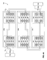
- FIG. 1 is a block diagram of an example of a simplified Internet Protocol (IP) over Synchronous Optical Network (SONET) link 100 of a multi-layer network.
- IP Internet Protocol
- SONET Synchronous Optical Network
- the link 100 represents the communication route employed to carry data packets between a first IP router 110 a and a second IP router 110 b , as described in greater detail below.
- Not shown in FIG. 1 are other portions of the multi-layer network that may also be employed in alternative situations to couple the routers 110 a , 110 b.
- the link 100 includes the first router 110 a and the second router 110 b for transmitting data between various communication devices, such as computers, PDAs and the like.
- the routers 110 a , 110 b represent first and second devices of the network between which data packets are transferred.
- Coupling the first router 110 a and the second router 110 b are multiple wavelength division multiplexing (WDM) systems 130 a , 130 b and 130 c , coupled back-to-back to form a path.
- Each WDM system 130 a - 130 c employs wavelength division multiplexing to provide multiple optical communication channels over a single optical connection.
- Any number of WDM systems 130 a - 130 c may be employed to couple the first router 110 a and the second router 110 b together in alternative embodiments of the invention so that packets of data may be transferred from the first router 110 a to the second router 110 b , and vice-versa.
- other optical communication mechanisms such as dense wavelength division multiplexing (DWDM) systems, may be employed to similar end.
- communication mechanisms other than optical communication links may be utilized to couple the first and second routers 110 a , 110 b.
- DWDM dense wavelength division multiplexing
- a “packet-over-SONET” (POS) interface 120 translates data between the electrical signals of the router 110 and the optical signals of the WDM system 130 .
- POS Packet-over-SONET
- a POS interface 120 a resides between the first router 110 a and the first WDM system 130 a
- a second POS interface 120 b resides between the second router 110 b and the last WDM system 130 c .
- Each POS interface 120 also performs the required data conversion between IP packets and SONET frames.
- the POS interface 120 may reside within the router 110 , or may be located externally thereto.
- each WDM system 130 a - 130 c contains two WDM terminals 132 , each of which contains one or more WDM transceivers 138 .
- Those WDM transceivers 138 which form the route between the routers 110 a , 110 b act as intermediate devices for transmitting and receiving optical data between the routers 110 a , 110 b .
- Each WDM transceiver 138 contains a bidirectional long reach interface 134 and a bidirectional short reach interface 136 for interchange of optical data.
- the long reach interface 134 couples a transceiver 138 of one WDM terminal 132 to a transceiver 138 of another WDM terminal 132 within a single WDM system 130 a - 130 c
- the short reach interface 136 connects a transceiver 138 of one WDM terminal 132 to a transceiver 138 of another WDM terminal 132 of an adjoining WDM system 130 a - 130 c , or to one of the routers 110 a , 110 b .
- the short reach interfaces 136 are employed to couple WDM systems 130 a - 130 c together, while the long reach interfaces 134 transfer optical signals between the two WDM terminals 132 of the same WDM system 130 a - 130 c.
- one or more optical switches may also be employed to connect some portion of the various WDM systems 130 a - 130 c or other network devices together in a variety of configurations to couple two or more routers 110 together optically.
- embodiments of the invention to be described below, may operate on such alternative link configurations and many others without departing from the scope of the invention.
- Location and interconnection information describing the identity and order of the WDM systems 130 a - 130 c and their various components comprising the connection between the routers 110 a , 110 b of the link 100 is often recorded into a facility management system (FMS) associated with the network by way of a manual, and hence error-prone, process. Also, this information is rarely updated to represent changes that have been made in the route, especially those made automatically by the routers 110 in response to detected failure conditions. In addition, if optical switches are employed in the route, changes to the route may be made quickly and easily, thereby rendering the stored connection information essentially obsolete. As a result, a more automated method for determining the route for data packets between the routers 110 a , 110 b would be beneficial.
- FMS facility management system
- Each WDM terminal 132 when employing the SONET protocol, typically reports to a SONET management system (SMS) various error signals or “alarms” to indicate the occurrence of various error or alarm conditions detected at one or more of the WDM transceivers 138 of WDM terminals 132 .
- SMS SONET management system
- the transceiver 138 informs the SMS of the error, and passes the erroneous data packet along without correction by way of its long reach interface 134 to a second WDM transceiver 138 .
- each WDM transceiver 138 will detect the same error, along with any other errors that were induced in the long reach interface 134 .
- each WDM transceiver 138 issues a single SONET alarm for one or more error or alarm conditions encountered within a fixed time segment, or “bin,” of fifteen minutes in length to reduce the total number of alarms generated by the link 100 .
- SONET alarms such as CV (code violation) alarms, ES (errored seconds) alarms and SES (severe errored seconds) alarms
- CV alarms indicate the presence of parity errors in one or more SONET bytes
- ES and SES alarms indicate the number of one-second intervals containing data or other errors within a particular 15-minute time period.
- Other SONET alarms such as the alarm indicating signal (AIS), exhibit different, programmable behavior.
- AIS alarm indicating signal
- each WDM transceiver 138 may be programmed to forward over its associated short reach interface 136 an AIS alarm received over its long reach interface 134 .
- forwarding may be suppressed.
- AIS alarms received over a short reach interface 136 may be either forwarded over the opposing long reach interface 134 , or suppressed.
- the transceiver 138 may be configured to report or suppress AIS alarms to the SMS.
- an identification of the transceiver 138 generating the alarm is provided, as well as the WDM terminal 132 upon which the transceiver is installed.
- the transceiver 138 is identified by way of a shelf number and a slot number, indicating the physical location of the transceiver 138 within the WDM terminal 132 .
- embodiments of the present invention provide a method 200 for tracing a communication route through a communication network over which data packets are transferred from a first device to a second device of the network.
- a first signal is transferred from the first device to the second device to cause a plurality of intermediate devices to report first information concerning the first signal (operation 202 ).
- the first information is processed to identify the intermediate devices as defining the communication route (operation 204 ).
- the intermediate devices are then configured so that a second signal, when sent from the first device toward the second device, causes a subset of the intermediate devices to report second information concerning the second signal (operation 206 ).
- the second signal is transferred from the first device toward the second device (operation 208 ).
- the second information is then processed to identify the subset of the intermediate devices as a portion of a sequence of the intermediate devices defining the communication route (operation 210 ).
- the intermediate devices are reconfigured (operation 206 ), the second signal is retransferred (operation 208 ), and the second information reprocessed (operation 210 ) repeatedly until the sequence of the intermediate devices defining the communication route is determined.
- the methods described herein may also be embodied in a digital storage medium for storing a program comprising instructions executable on a processor for implementing the foregoing method.
- FIGS. 3A and 3B illustrate a method 300 according to an embodiment of the invention for determining the route of data packets transferred between the first router 110 a and the second router 110 b by way of the WDM transceivers 138 .
- initiation of the various actions occurs by way of a remote terminal (not shown in FIG. 1 ) in communication with the routers 110 (operation 302 ).
- the remote terminal may access a network management system (NMS) (in this case, the SONET management system (SMS)) through one or more application programming interfaces (APIs), and thus may query the NMS regarding alarm conditions and the like reported by the WDM transceivers 138 .
- NMS network management system
- APIs application programming interfaces
- a user or network manager may initiate an automatic tracing function to determine the route taken by data packets via the WDM transceivers 138 between the first and second routers 110 .
- each of the routers 110 is notified to indicate that SONET-level errors are going to be generated by one router to be received by the other router (operation 304 ).
- the remote terminal directly notifies both routers 110 , indicating which will be generating the errors first.
- the first router 110 a may be notified by the remote terminal, after which the first router 110 a notifies the second router 110 b via the link 100 .
- Each of the routers 110 then waits for an error-free period of time exceeding the size of the error bins employed in SONET (operation 306 ).
- each router 110 waits for a length of time exceeding fifteen minutes to ensure no naturally-produced errors (i.e., errors generated during normal data transfer operations) are encountered during the current error bin. If a naturally-produced error in a SONET frame is encountered in other traffic between the routers 110 , the routers 110 wait another fifteen minutes until an error-free bin is encountered. The wait period helps isolate naturally-produced errors from the errors intentionally generated by the trace. Once such an error-free period occurs, each of the routers 110 signals the other over the link 100 to indicate detection of this period (operation 308 ).
- each router 110 disables “IP layer restoration” (operation 310 ).
- IP level restoration describes the actions of the routers 110 to reconfigure the network topology at the IP level to circumvent the link 100 or portions thereof that are considered defective.
- IP level restoration involves the modification of a routing table maintained by each router 110 .
- These routing tables typically must be synchronized with each other to ensure effective routing.
- this synchronization is rather time-consuming, so the routers 110 typical wait for a relatively length period of time, such as 200 milliseconds, before attempting IP layer restoration.
- Allowing IP layer restoration would defeat the purpose of determining the current route between the routers 110 , as that route would no longer be valid if errors transmitted during detection of the route caused the route to be deemed unusable. Thus, IP layer restoration is disabled to allow generation and transmission of SONET alarms without causing subsequent network rerouting.
- each of the routers may alter the value of its “carrier timer,” which typically is a configurable amount of time during which a router 110 will wait for the communication link 100 to recover before initiating IP layer restoration.
- the carrier timer is set to a sufficiently high value to ensure that IP layer restoration, and hence rerouting, will not occur during the tracing of the route, as described below. In such a case, the optical network layer underlying the IP layer would then be primarily responsible for reestablishing communication in the presence of errors before the IP layer initiates restoration.
- the carrier timer of each router 110 is set to five seconds.
- One of the routers 110 (for example, the first router 110 a ) then generates an unconditionally propagated SONET alarm as a first signal to be detected by the other router 110 (operation 312 ).
- the first router 110 a causes an alarm condition which will be propagated through all WDM transceivers 138 along the yet-to-be-traced route to the second router 110 b regardless of how each WDM transceiver 138 is configured regarding the forwarding of alarm conditions.
- the SONET alarm is a code violation (CV), which indicates a data error in the data packet being transferred from the first router 110 a to the second router 110 b .
- CV code violation
- the POS interface 120 of each router 110 is capable of generating burst data errors solely in the SONET overhead bytes in order to trigger CV alarms in the WDM transceivers 138 receiving the data without affecting the data at the IP level.
- an integrated circuit within the POS interface 120 such as a PM5380 ATM and Packet Over SONET/SDH Physical Layer Device by PMC-Sierra, Inc., or the ⁇ PD98414 ATM SONET Framer by NEC Electronics, Inc., may be employed to generate code violations in the SONET frame bytes.
- the B1 byte of the SONET section overhead which carries the section bit-interleaved parity code (BIP-8) byte, may be corrupted to cause a parity error, and hence a code violation, in the receiving WDM transceiver 138 .
- Other methods for generating a CV alarm such as corrupting the B2 byte (i.e., the line bit-interleaved parity code (BIP-8) byte), the B3 byte (i.e., the synchronous transport signals (STS) path bit-interleaved parity code (path BIP-8) byte), and others, may be performed in the alternative.
- alteration is performed on the SONET frame itself rather than the IP packets carried inside the SONET frame due to the inability of most IP routers to generate errors, the inability of SONET framers to detect IP packet errors, and the relative ease with which various bytes of the SONET frame may be accessed and modified.
- the length of each burst error may range from one to some small number n so that the overall error rate remains below some error rate, such as 1 ⁇ 10 ⁇ 9 .
- the length of each burst error is reported in a CV alarm and is employed by the remote terminal to discern the CV alarms generated by the route tracing function from those which occur naturally, as is discussed further below.
- the ability of the remote terminal to distinguish between generated and normally-occurring errors is enhanced, thus improving the accuracy of the route tracing function.
- a different burst error length may be employed for the generated errors to help distinguish between naturally-produced errors and those errors generated for the route-tracing function.
- the first router 110 a generates the first burst error or other alarm at a random time T 1 .
- the first router 110 a also sends a message to the second router 110 b indicating the time value of T 1 so that the second router may distinguish the first burst error from other naturally-produced errors that may be occurring over the link 100 (operation 314 ).
- the length of the generated burst error may also be transferred so that the second router 110 b may discern generated errors from natural errors. If the second router 110 b detects the presence of the first burst error, the second router 110 b records the time T 1 and signals the first router 110 a to confirm that the first burst error was detected (operation 316 ).
- Both the first and the second routers 110 a , 110 b then reset their corresponding carrier timers, or re-enable IP layer restoration (operation 318 ), and return to waiting for a bin length of fifteen minutes of no errors during normal operation of the link 100 (operation 306 ).
- the disabling of IP layer restoration executed earlier (operation 310 ) is a timed operation which involves an automatic re-enabling of IP layer restoration capability after a specified amount of time. Therefore, a separate re-enabling operation (operation 318 ) would not be necessary in that particular case.
- each of the random time stamps T 1 through T N are chosen so that the pattern, or “signature,” of the time stamps is different than that produced by normal errors produced over the link 100 .
- a particular repeating pattern of low values for the length of each burst error such as three followed by eight, may be employed to distinguish the generated errors from naturally-occurring errors.
- the remote terminal may use both the timestamp and the length of the burst error to detect the SONET alarms generated for route tracing purposes.
- the second router 110 b may also generate a second set of burst errors 110 b to the first router 110 a , resulting in a second set of time stamps T 1 ′ through T N ′ (operations 306 - 318 ).
- the number of time stamps generated by the first router 110 a and the second router 110 b may be different.
- the second router 110 b generates its burst errors to develop the second set of time stamps after the first set of time stamps T 1 through T N have been collected.
- the first router 110 a and the second router 110 b generate burst errors concurrently so that the two sets of time stamps are also collected concurrently to reduce the amount of time required to collect the time stamps.
- each WDM transceiver 138 constituting part of the route taken by the data packets between the first and second routers 110 a , 110 b detects the errors and reports them to the SMS.
- Each error report to the SMS also includes a time stamp indicating the time at which the burst error was detected, and the length of the particular burst error, as described above.
- the remote terminal may then query the SMS to determine the identity of each WDM transceiver 138 that issued a CV alarm at each of the particular time stamps T 1 through T N , thereby identifying a first set of WDM transceivers 138 , referred to herein as TR 1 through TR M , that may form the route through the link 100 from the first router 110 a to the second router 110 b (operation 320 ).
- the remote terminal also queries the SMS to identify each WDM transceiver 138 that issued a CV alarm at each of the second set of time stamps T 1 ′ through T N ', thereby producing a second set of WDM transceivers 138 , labeled herein as TR 1 ′ through TR P ′, that may form the route from the second router 110 b to the first router 110 a (operation 322 ).
- the two sets of WDM transceivers 138 may not coincide (i.e., TR 1 through TR M are not the same as TR 1 ′ through TR P ′), thereby indicating that the path from the first router 110 a to the second router 110 b is different from the path from the second router 110 b to the first router 110 a.
- the remote terminal employs the use of a conditionally propagated alarm as a second signal to determine the sequence.
- the conditionally propagated alarm is the AIS alarm mentioned above.
- the remote terminal initializes the WDM transceivers TR 1 -TR M by signaling each of the transceivers to clear its fifteen minute bin alarms and counters (operation 324 ).
- the remote terminal also informs each of the WDM transceivers TR 1 -TR M in the path to prevent forwarding of AIS alarms received over the long reach interface 134 of each of the transceivers (operation 324 ).
- the remote terminal also signals the first and second routers 110 a , 110 b to begin the process of sending and receiving messages incorporating MS alarms (operation 326 ).
- the remote terminal also informs the routers 110 a , 110 b which of the two will be sending the alarms.
- the sending router for example, the first router 110 a
- the first router 110 a and the second router 110 b Prior to the sending of the AIS alarms, the first router 110 a and the second router 110 b each disables its IP layer restoration capability, or modifies its carrier timer to a level sufficiently high to prevent the routers 110 a , 110 b from attempting to invoke their IP layer restoration capability while the AIS alarms are being transmitted (operation 328 ). In so doing, the routers 110 a , 110 b substantially limit their capacity to reconfigure the route connecting the routers 110 a , 110 b , as discussed above.
- the first router 110 a then sends an AIS alarm in a message to the second router 110 b at a random time T 1 ′′ (operation 330 ).
- FIG. 4A depicts the extent which the MS alarm propagates along the link 100 by way of dashed arrows. Given that each of the identified WDM transceivers TR 1 through TR M have been configured to not propagate an AIS alarm received over its long reach interface 134 , an AIS alarm will propagate through a first WDM transceiver TR X1 encountered, which is directly coupled with the first router 110 a , by way of the short reach interface 136 of the first transceiver TR X1 .
- the first transceiver TR X1 resides on the WDM terminal 132 of the WDM system 130 a first encountered along the route from the first router 110 a to the second router 110 b .
- the AIS alarm is propagated to a second WDM transceiver TR Y1 by way of the long reach interface 134 of the first and second transceivers TR X1 , TR Y1 .
- the second transceiver TR Y1 thus resides within the second WDM terminal 132 of the first WDM system 130 a .
- the second transceiver TR Y1 As the second transceiver TR Y1 received the current message over its long reach interface 134 , the second transceiver TR Y1 does not propagate the AIS alarm when it transfers the current message over its short reach interface 136 to the next WDM transceiver, thus ceasing any further propagation of that alarm. Therefore, only the first two WDM transceivers TR X1 , TR Y1 have detected the AIS alarm, and have subsequently reported the alarm to the SMS. The message from the first router 110 a then continues on to the second router 110 b along the link 100 , but without the AIS alarm signal.
- each transceiver TR X1 , TR Y1 typically reports the time the AIS alarm was received, which in this example is the time stamp T 1 ′′.
- each transceiver TR X1 , TR Y1 indicates in the report whether the AIS alarm was received over its short reach interface 136 or its long reach interface 134 .
- the IP layer restoration or carrier timer is then restored in the routers 110 a , 110 b to return the routers 110 a , 110 b to their normal operating state (operation 332 ).
- the remote terminal queries the SMS for each of the identified transceivers TR 1 -TR M to determine the identity of the two transceivers TR X1 , TR Y1 that reported the AIS alarm at the time stamp T 1 ′′ (operation 334 ).
- the remote terminal determines which of the two transceivers TR X1 , TR Y1 first received the AIS alarm by consulting the report to the SMS to determine whether the short reach interface 136 or the long reach interface 134 of each of the transceivers TR X1 , TR Y1 received the alarm.
- the remote terminal can determine that the first transceiver TR X1 , having received the alarm over its short reach interface 136 , was the first in the sequence of WDM transceivers TR 1 -TR M to received the alarm, while the second transceiver TR Y1 , having received the alarm, from the first transceiver TR X1 over its long reach interface 136 , was the second transceiver in the sequence.
- the remote terminal is able to determine the first two transceivers TR X1 , TR Y1 in the route from the first router 110 a to the second router 110 b.
- the remote terminal then clears the fifteen minute bin alarms and counters for each of the identified WDM transceivers TR 1 -TR M (operation 336 ). Further, the remote terminal sets the long reach interface 134 of the second transceiver TR Y1 into AIS forwarding mode (operation 336 ).
- the first router 110 a and the second router 110 b Prior to the sending another AIS alarm, the first router 110 a and the second router 110 b again disable their IP layer restoration capability, or modify their carrier timers as before (operation 328 ). The first router 110 a is then free to generate another AIS alarm in a second message sent to the second router 110 b at a second time T 2 ′′ (operation 330 ).
- the IP layer restoration or carrier timer is then restored again in the routers 110 a , 110 b to return the routers 110 a , 110 b to their normal operating state (operation 332 ).
- the remote terminal then once again queries the SMS to determine which of the identified transceivers TR 1 -TR M received the alarm (operation 334 ). Having already determined the sequence along the route of the first two transceivers TR X1 , TR Y1 , the remote terminal identifies the second pair of transceivers TR X2 , TR Y2 as the next two transceivers in the route.
- the remote terminal can determine the proper order of the second pair of transceivers. In other words, since the third WDM transceiver TR X2 received the message via its short reach interface 136 , and the fourth transceiver TR Y2 received the message by way of its long reach interface 124 (from the third transceiver TR X2 ), the remote terminal ascertains the proper order of the third and fourth transceivers TR X2 , TR Y2 .
- the remote terminal again clears the fifteen minute bin alarms and counters for each of the identified WDM transceivers TR 1 -TR M (operation 336 ). Further, the remote terminal sets the long reach interface 134 of the fourth WDM transceiver TR Y2 to AIS forwarding mode so that the AIS alarm may propagate beyond the fourth transceiver TR Y2 to determine the next two WDM transceivers in the route (operation 336 ).
- This process continues in this fashion, with another message containing an AIS alarm being sent from the first IP router 110 a to the second router 110 b , followed by a query of the SMS by the remote terminal to determine the next two transceivers in the route.
- fewer or greater numbers of transceivers may be sequenced for each AIS alarm transferred.
- the remote terminal determines that no new WDM transceivers TR 1 -TR M are being detected by way of another AIS alarm message, the proper sequence of the identified WDM transceivers TR 1 -TR M along the route from the first router 110 a to the second router 110 b has been determined.
- the process of tracing the route may be considered completed.
- methods according to an embodiment of the invention utilize a first alarm or signal indication sent from one router 110 to another router 110 to identify the transceivers employed in the data packet route in the link 100 between the first and second routers 110 . Further, the actual sequence of the identified transceivers in the route is determined by the use of a second alarm or signal indication sent from one router 110 toward the other router 110 .
- Another difficulty may be the presence of an inordinate data error rate while a trace is being performed.
- CV alarms may occur more often than once every fifteen minutes, thus not allowing an alarm bin that is free from naturally-occurring burst errors.
- eliminating the requirement of a CV alarm-free period of fifteen minutes prior to the sending router 110 issuing a packet with a CV alarm condition may be necessary in order to perform the trace.
- This condition likely makes positive detection of the CV errors purposely produced from the sending router 110 at a particular time stamp by the WDM transceivers 138 and the receiving router 110 more difficult and error-prone, as complete correlation of each transceiver reporting a CV error to the time stamp signature chosen by the sending router 110 may be improbable.
- the multi-layer tracing methods disclosed herein produce useful tracing information in spite of the presence of a higher-than-normal data error rate.
- another unconditionally propagated alarm that is not affected by a high data error rate may be employed.
- the embodiments of the invention disclosed above employ well-known alarm signals and frame bytes currently defined within the SONET standard, and thus may be employed to trace a wide range of multi-layer network links. Other methods residing within the scope of the invention may also be devised which employ less standard techniques. For example, within the context of the IP-over-SONET-over-WDM link described above, the AIS alarm may be replaced with another alarm signal that is conditionally propagated along the route being traced. Additionally, any SONET frame bytes that are currently unused or defined may be employed to pass along a special-purpose alarm signal detectable by each of the transceivers 138 along the route being traced.
Abstract
Description
Claims (20)
Priority Applications (1)
| Application Number | Priority Date | Filing Date | Title |
|---|---|---|---|
| US11/095,833 US7843838B1 (en) | 2005-03-31 | 2005-03-31 | Communication network route tracing |
Applications Claiming Priority (1)
| Application Number | Priority Date | Filing Date | Title |
|---|---|---|---|
| US11/095,833 US7843838B1 (en) | 2005-03-31 | 2005-03-31 | Communication network route tracing |
Publications (1)
| Publication Number | Publication Date |
|---|---|
| US7843838B1 true US7843838B1 (en) | 2010-11-30 |
Family
ID=43215654
Family Applications (1)
| Application Number | Title | Priority Date | Filing Date |
|---|---|---|---|
| US11/095,833 Expired - Fee Related US7843838B1 (en) | 2005-03-31 | 2005-03-31 | Communication network route tracing |
Country Status (1)
| Country | Link |
|---|---|
| US (1) | US7843838B1 (en) |
Cited By (4)
| Publication number | Priority date | Publication date | Assignee | Title |
|---|---|---|---|---|
| US20110085449A1 (en) * | 2009-10-07 | 2011-04-14 | Vinod Jeyachandran | Network path discovery and analysis |
| US20120087251A1 (en) * | 2009-07-28 | 2012-04-12 | Huawei Technologies Co., Ltd. | Method, system and network device for node configuration and path detection |
| CN108038048A (en) * | 2017-12-05 | 2018-05-15 | 郑州云海信息技术有限公司 | Statistical method, device and the readable storage medium storing program for executing that individual data pack receiving and transmitting takes |
| US20180367439A1 (en) * | 2016-02-16 | 2018-12-20 | Huawei Technologies Co., Ltd. | Packet transmission method and apparatus |
Citations (18)
| Publication number | Priority date | Publication date | Assignee | Title |
|---|---|---|---|---|
| US6026073A (en) * | 1995-08-07 | 2000-02-15 | British Telecommunications Public Limited Company | Route finding in communications networks |
| US6078596A (en) * | 1997-06-26 | 2000-06-20 | Mci Communications Corporation | Method and system of SONET line trace |
| US6094682A (en) * | 1998-03-13 | 2000-07-25 | Fujitsu Limited | Method of constructing the path information of a network management system |
| US6239699B1 (en) * | 1999-03-03 | 2001-05-29 | Lucent Technologies Inc. | Intelligent alarm filtering in a telecommunications network |
| US20010041538A1 (en) * | 1999-12-10 | 2001-11-15 | Kai Schmitt | Method and system for monitoring a radio transmission link |
| US6377543B1 (en) * | 1997-08-13 | 2002-04-23 | Telecommunications Research Laboratories | Path restoration of networks |
| US20020080829A1 (en) * | 1998-07-22 | 2002-06-27 | Yoram Ofek | Link transmission control with common time reference |
| US6483809B2 (en) * | 1996-10-11 | 2002-11-19 | Nec Corporation | High speed transfer of failure information in an ATM network |
| US20020191241A1 (en) * | 2001-06-13 | 2002-12-19 | Emery Jeffrey Kenneth | Network operating system with topology autodiscovery |
| US20040008988A1 (en) * | 2001-10-01 | 2004-01-15 | Gerstal Ornan A. | Link discovery, verification, and failure isolation in an optical communication system |
| US20040120710A1 (en) * | 2002-12-09 | 2004-06-24 | Nabil Seddigh | Method and system for light path monitoring in an optical communication network |
| US6763190B2 (en) * | 2000-03-03 | 2004-07-13 | Lucent Technologies Inc. | Network auto-provisioning and distributed restoration |
| US20050086555A1 (en) * | 2003-10-20 | 2005-04-21 | David Langridge | Optical communications network |
| US20050249119A1 (en) * | 2004-05-10 | 2005-11-10 | Alcatel | Alarm indication and suppression (AIS) mechanism in an ethernet OAM network |
| US20050281192A1 (en) * | 2004-06-18 | 2005-12-22 | Cisco Technology, Inc. | Consistency between MPLS forwarding and control planes |
| US20060031573A1 (en) * | 2004-05-24 | 2006-02-09 | Tellabs Operations, Inc. | Method and system for autodiscovery of a network path |
| US7158721B2 (en) * | 2002-02-25 | 2007-01-02 | Corrigent Systems Ltd. | Performance monitoring of multiple channels in an automatic protection switched network |
| US20070274227A1 (en) * | 2006-05-24 | 2007-11-29 | At&T Corp. | Network latency analysis packet and method |
-
2005
- 2005-03-31 US US11/095,833 patent/US7843838B1/en not_active Expired - Fee Related
Patent Citations (18)
| Publication number | Priority date | Publication date | Assignee | Title |
|---|---|---|---|---|
| US6026073A (en) * | 1995-08-07 | 2000-02-15 | British Telecommunications Public Limited Company | Route finding in communications networks |
| US6483809B2 (en) * | 1996-10-11 | 2002-11-19 | Nec Corporation | High speed transfer of failure information in an ATM network |
| US6078596A (en) * | 1997-06-26 | 2000-06-20 | Mci Communications Corporation | Method and system of SONET line trace |
| US6377543B1 (en) * | 1997-08-13 | 2002-04-23 | Telecommunications Research Laboratories | Path restoration of networks |
| US6094682A (en) * | 1998-03-13 | 2000-07-25 | Fujitsu Limited | Method of constructing the path information of a network management system |
| US20020080829A1 (en) * | 1998-07-22 | 2002-06-27 | Yoram Ofek | Link transmission control with common time reference |
| US6239699B1 (en) * | 1999-03-03 | 2001-05-29 | Lucent Technologies Inc. | Intelligent alarm filtering in a telecommunications network |
| US20010041538A1 (en) * | 1999-12-10 | 2001-11-15 | Kai Schmitt | Method and system for monitoring a radio transmission link |
| US6763190B2 (en) * | 2000-03-03 | 2004-07-13 | Lucent Technologies Inc. | Network auto-provisioning and distributed restoration |
| US20020191241A1 (en) * | 2001-06-13 | 2002-12-19 | Emery Jeffrey Kenneth | Network operating system with topology autodiscovery |
| US20040008988A1 (en) * | 2001-10-01 | 2004-01-15 | Gerstal Ornan A. | Link discovery, verification, and failure isolation in an optical communication system |
| US7158721B2 (en) * | 2002-02-25 | 2007-01-02 | Corrigent Systems Ltd. | Performance monitoring of multiple channels in an automatic protection switched network |
| US20040120710A1 (en) * | 2002-12-09 | 2004-06-24 | Nabil Seddigh | Method and system for light path monitoring in an optical communication network |
| US20050086555A1 (en) * | 2003-10-20 | 2005-04-21 | David Langridge | Optical communications network |
| US20050249119A1 (en) * | 2004-05-10 | 2005-11-10 | Alcatel | Alarm indication and suppression (AIS) mechanism in an ethernet OAM network |
| US20060031573A1 (en) * | 2004-05-24 | 2006-02-09 | Tellabs Operations, Inc. | Method and system for autodiscovery of a network path |
| US20050281192A1 (en) * | 2004-06-18 | 2005-12-22 | Cisco Technology, Inc. | Consistency between MPLS forwarding and control planes |
| US20070274227A1 (en) * | 2006-05-24 | 2007-11-29 | At&T Corp. | Network latency analysis packet and method |
Non-Patent Citations (3)
| Title |
|---|
| "8-Channel OC-3c ATM and POS Physical Layer Device" PMC (PMC-Sierra, Inc. 2002) PM5380 S/UNI 8x155 (2 sheets). |
| "PM5380 S/UNI 8X155 8 Channel 155Mbit/s ATM and Packet over Sonet/SDH Physical Layer Device" obtained Feb. 15, 2005, http://www.pmc-sierra.com/products/details/pm5380/ pp. 1-5. |
| "uPD98414 2.4 Gbps ATM Sonet Framer" NEC Document # S14306EUTVOPBOO, www.necel.com. |
Cited By (8)
| Publication number | Priority date | Publication date | Assignee | Title |
|---|---|---|---|---|
| US20120087251A1 (en) * | 2009-07-28 | 2012-04-12 | Huawei Technologies Co., Ltd. | Method, system and network device for node configuration and path detection |
| US8861378B2 (en) * | 2009-07-28 | 2014-10-14 | Huawei Technologies Co., Ltd. | Method, system and network device for node configuration and path detection |
| US20110085449A1 (en) * | 2009-10-07 | 2011-04-14 | Vinod Jeyachandran | Network path discovery and analysis |
| US8811193B2 (en) * | 2009-10-07 | 2014-08-19 | Riverbed Technology, Inc. | Network path discovery and analysis |
| US20180367439A1 (en) * | 2016-02-16 | 2018-12-20 | Huawei Technologies Co., Ltd. | Packet transmission method and apparatus |
| US10721155B2 (en) * | 2016-02-16 | 2020-07-21 | Huawei Technologies Co., Ltd. | Packet transmission method and apparatus |
| US11456943B2 (en) | 2016-02-16 | 2022-09-27 | Huawei Technologies Co., Ltd. | Packet transmission method and apparatus |
| CN108038048A (en) * | 2017-12-05 | 2018-05-15 | 郑州云海信息技术有限公司 | Statistical method, device and the readable storage medium storing program for executing that individual data pack receiving and transmitting takes |
Similar Documents
| Publication | Publication Date | Title |
|---|---|---|
| Mas et al. | An efficient algorithm for locating soft and hard failures in WDM networks | |
| EP2458797B1 (en) | Method, device and system for updating ring network topology information | |
| US7333425B2 (en) | Failure localization in a transmission network | |
| KR100893783B1 (en) | A method for analyzing mutual relation of alarms in a synchronous optical transmission network | |
| US6359857B1 (en) | Protection switching trigger generation | |
| US7830784B2 (en) | Intelligent network restoration | |
| US20070140126A1 (en) | Method and system for originating connectivity fault management (CFM) frames on non-CFM aware switches | |
| CN101986604A (en) | Link fault positioning method and system of packet transport network (PTN) | |
| JP2006115496A (en) | Network monitoring method and network element | |
| US9203719B2 (en) | Communicating alarms between devices of a network | |
| CN102088387A (en) | Tunnel protection method and device of ring network | |
| US10601537B2 (en) | Fault propagation in segmented protection | |
| US7843838B1 (en) | Communication network route tracing | |
| EP2129042B1 (en) | A multicast network system, node and a method for detecting a fault of a multicast network link | |
| US20120294603A1 (en) | Method and System for Service Protection | |
| CN105634935A (en) | Device and method for detecting service layer signal failure | |
| CN101494801B (en) | Method, system and network appliance for fault recovery | |
| CN102792636A (en) | Methods, apparatus and communication network for providing restoration survivability | |
| KR20020077000A (en) | Methode for fault management of intranet OSI layer | |
| WO2015120581A1 (en) | Traffic loop detection in a communication network | |
| US7509438B1 (en) | Bi-directional line switched ring support for path trace monitoring on a protection path | |
| EP2849370B1 (en) | Method for an enhanced failure localization in an optical data transmission network, optical data transmission network and program product | |
| WO2021244390A1 (en) | Alarm processing method and apparatus | |
| CN114244468A (en) | Method, storage medium and equipment for rapidly positioning fault point of OTN link | |
| Mas et al. | An efficient fault localization algorithm for IP/WDM networks |
Legal Events
| Date | Code | Title | Description |
|---|---|---|---|
| AS | Assignment |
Owner name: SPRINT COMMUNICATIONS COMPANY L.P., KANSAS Free format text: ASSIGNMENT OF ASSIGNORS INTEREST;ASSIGNORS:HUANG, RENXIANG;WHITE, IAN M.;PAN, JAMES J.;REEL/FRAME:016450/0216 Effective date: 20050330 |
|
| FPAY | Fee payment |
Year of fee payment: 4 |
|
| AS | Assignment |
Owner name: DEUTSCHE BANK TRUST COMPANY AMERICAS, NEW YORK Free format text: GRANT OF FIRST PRIORITY AND JUNIOR PRIORITY SECURITY INTEREST IN PATENT RIGHTS;ASSIGNOR:SPRINT COMMUNICATIONS COMPANY L.P.;REEL/FRAME:041895/0210 Effective date: 20170203 |
|
| FEPP | Fee payment procedure |
Free format text: MAINTENANCE FEE REMINDER MAILED (ORIGINAL EVENT CODE: REM.) |
|
| LAPS | Lapse for failure to pay maintenance fees |
Free format text: PATENT EXPIRED FOR FAILURE TO PAY MAINTENANCE FEES (ORIGINAL EVENT CODE: EXP.); ENTITY STATUS OF PATENT OWNER: LARGE ENTITY |
|
| STCH | Information on status: patent discontinuation |
Free format text: PATENT EXPIRED DUE TO NONPAYMENT OF MAINTENANCE FEES UNDER 37 CFR 1.362 |
|
| FP | Lapsed due to failure to pay maintenance fee |
Effective date: 20181130 |
|
| AS | Assignment |
Owner name: SPRINT COMMUNICATIONS COMPANY L.P., KANSAS Free format text: TERMINATION AND RELEASE OF FIRST PRIORITY AND JUNIOR PRIORITY SECURITY INTEREST IN PATENT RIGHTS;ASSIGNOR:DEUTSCHE BANK TRUST COMPANY AMERICAS;REEL/FRAME:052969/0475 Effective date: 20200401 |