US7831782B1 - Roll-back log to provide data consistency - Google Patents
Roll-back log to provide data consistency Download PDFInfo
- Publication number
- US7831782B1 US7831782B1 US10/881,724 US88172404A US7831782B1 US 7831782 B1 US7831782 B1 US 7831782B1 US 88172404 A US88172404 A US 88172404A US 7831782 B1 US7831782 B1 US 7831782B1
- Authority
- US
- United States
- Prior art keywords
- data
- volume
- new
- time
- roll
- Prior art date
- Legal status (The legal status is an assumption and is not a legal conclusion. Google has not performed a legal analysis and makes no representation as to the accuracy of the status listed.)
- Expired - Fee Related, expires
Links
Images


Classifications
-
- G—PHYSICS
- G06—COMPUTING; CALCULATING OR COUNTING
- G06F—ELECTRIC DIGITAL DATA PROCESSING
- G06F11/00—Error detection; Error correction; Monitoring
- G06F11/07—Responding to the occurrence of a fault, e.g. fault tolerance
- G06F11/16—Error detection or correction of the data by redundancy in hardware
- G06F11/1658—Data re-synchronization of a redundant component, or initial sync of replacement, additional or spare unit
- G06F11/1662—Data re-synchronization of a redundant component, or initial sync of replacement, additional or spare unit the resynchronized component or unit being a persistent storage device
-
- G—PHYSICS
- G06—COMPUTING; CALCULATING OR COUNTING
- G06F—ELECTRIC DIGITAL DATA PROCESSING
- G06F11/00—Error detection; Error correction; Monitoring
- G06F11/07—Responding to the occurrence of a fault, e.g. fault tolerance
- G06F11/14—Error detection or correction of the data by redundancy in operation
- G06F11/1402—Saving, restoring, recovering or retrying
- G06F11/1471—Saving, restoring, recovering or retrying involving logging of persistent data for recovery
-
- G—PHYSICS
- G06—COMPUTING; CALCULATING OR COUNTING
- G06F—ELECTRIC DIGITAL DATA PROCESSING
- G06F11/00—Error detection; Error correction; Monitoring
- G06F11/07—Responding to the occurrence of a fault, e.g. fault tolerance
- G06F11/14—Error detection or correction of the data by redundancy in operation
- G06F11/1402—Saving, restoring, recovering or retrying
- G06F11/1474—Saving, restoring, recovering or retrying in transactions
-
- G—PHYSICS
- G06—COMPUTING; CALCULATING OR COUNTING
- G06F—ELECTRIC DIGITAL DATA PROCESSING
- G06F11/00—Error detection; Error correction; Monitoring
- G06F11/07—Responding to the occurrence of a fault, e.g. fault tolerance
- G06F11/16—Error detection or correction of the data by redundancy in hardware
- G06F11/20—Error detection or correction of the data by redundancy in hardware using active fault-masking, e.g. by switching out faulty elements or by switching in spare elements
- G06F11/2097—Error detection or correction of the data by redundancy in hardware using active fault-masking, e.g. by switching out faulty elements or by switching in spare elements maintaining the standby controller/processing unit updated
-
- G—PHYSICS
- G06—COMPUTING; CALCULATING OR COUNTING
- G06F—ELECTRIC DIGITAL DATA PROCESSING
- G06F2201/00—Indexing scheme relating to error detection, to error correction, and to monitoring
- G06F2201/82—Solving problems relating to consistency
Definitions
- mirroring data would fulfill the business needs met by data replication technology.
- Two facts relating to distributed data centers make mirroring inadequate. More particularly, distances between primary and secondary data centers, routing hops, and momentary network overloads can make data update transmission time too long in terms of its affect on application response. Additionally, brief network outages can occur frequently enough to make the frequent mirror resynchronization they would imply unacceptable.
- Mirror resynchronization can be a lengthy process that oftentimes requires a full resynchronization in which data is copied from one minor to the other in a block by block process until all data blocks of the minor have been copied.
- a system or method for reestablishing data consistency between data volume P and its real time or near real time copy volume S When volumes P and S enter a state of data inconsistency, data consistency can be restored through use of roll-back and/or roll-forward logs.
- the roll-forward log stores new data to be written to volume P.
- the roll-back log stores existing data of volume S before the existing data of volume S is overwritten with new data.
- the roll-back log can be used to incrementally restore volume S to a prior data state in reverse chronological order, while a roll-forward log can be used to incrementally restore volume S in forward chronological to equal the data state of volume P.
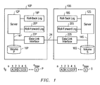
- FIG. 1 shows a block diagram of relevant components in a data processing system employing one embodiment of the present invention and a graphical representation of volume P and its real time or near real time copy volume S;
- FIGS. 2 a and 2 b illustrate relevant aspects of writing data to roll-back and roll-forward logs of the data centers in FIG. 1 in accordance with one embodiment of the present invention
- FIGS. 3 a and 3 b illustrate the data state of data volume P, volume S, the roll-back logs, and roll-forward logs after performing the process steps shown in FIG. 2 a and prior to failure of the data link between the data centers of FIG. 1 ;
- FIGS. 3 c and 3 d illustrate the data state of data volume P, volume S, the roll-back logs, and roll-forward logs after performing the process steps shown in FIG. 2 a and after failure of the data link between the data centers of FIG. 1 ;
- FIG. 4 illustrate operational aspects of restoring volume S to the data state of volume P after reestablishment of the data link between the data centers of FIG. 1 ;
- FIGS. 5 a and 5 b illustrate the data state of data volume P, volume S, the roll-back logs, and roll-forward logs after performing process steps shown in FIG. 4 ;
- FIGS. 6 a and 6 b illustrate the data state of data volume P, volume S, the roll-back logs, and roll-forward logs after performing process steps shown in FIGS. 2 a and 2 b and after failure of the data link between the data centers of FIG. 1 ;
- FIG. 7 illustrate operational aspects of restoring volume S to the data state of volume P after reestablishment of the data link between the data centers of FIG. 1 ;
- FIGS. 8 a - 8 d illustrates the data state of data volume P, volume S, the roll-back logs, and roll-forward logs after performing the process steps shown in FIG. 7 .
- This invention relates to a system or method for maintaining data consistency between data volume P and its real time or near real time copy volume S.
- the present invention will be described with respect to maintaining data consistency on the volume level, it being understood that the present invention may be applied to maintaining data consistency on the file system or database level.
- Volume S may take form in a replica of volume P, or volume S may take form in a mirror of volume P.
- data consistency can be restored through use of roll-back and/or roll-forward logs.
- a roll-back log can be used to incrementally restore volume P or volume S to a prior data state in reverse chronological order
- a roll-forward log can be used to incrementally restore one of the volumes P or S in forward chronological order to the data state of the other of the data volumes. While the present invention will be described with reference to maintaining data consistency between a single volume and its mirror or replica, the present invention could also be used for maintaining data consistency between several data volumes and their mirrors or replicas.
- FIG. 1 illustrates in block diagram form, relevant components of exemplary data centers. More particularly, FIG. 1 shows a primary data center 10 P and a secondary data center 10 S coupled together via a data link 24 .
- Primary data center P includes a computer system 12 P coupled directly or indirectly to a memory system 16 P that stores data volume P.
- Secondary data center 10 S also includes a computer system 12 S coupled directly or indirectly to a memory system 16 S that stores volume S.
- Computer systems 12 P and 12 S can be any computer or other data processing device.
- computer systems 12 P and 12 S can be conventional personal computers, servers, special purpose computers, or the like.
- computer systems 12 P and 12 S are presumed to take form in servers each having one or more processors for executing instructions.
- the present invention can be implemented by server 12 P executing instructions stored in memory (not shown), by server 12 S executing instructions stored in memory (not shown), or by a combination of servers 12 P and 12 S executing instructions stored in memory.
- Servers 12 P and 12 S are coupled to client computer systems (not show). Servers 12 P and/or 12 S may receive transaction requests directly or indirectly from the client computer systems. Each of the server 12 P and 12 S execute an application that generates transactions that directly or indirectly read data from or write data to volumes P and S, respectively, in response to receiving and processing transaction requests from the client computer systems.
- server 12 P is designated as the primary server for processing transaction requests from client computer systems, and server 12 S is provided for disaster recovery purposes.
- volume S may take form as a replica of volume P with server 12 S standing ready to receive and process transaction requests from the client computer systems using replica S in the event data center 12 P is rendered unusable by, for example, failure of server 12 P.
- server 12 P fails as a result of, for example, hardware failure
- transaction requests from client computer systems are redirected to data center 10 S for processing.
- servers 12 P and 12 S are clustered together through use of well known clustering software (not shown) even though servers 12 P and 12 S may be remotely located from each other through use of a network transport protocol such as dense wave division multiplexing.
- volumes P and S are maintained as mirrors.
- Server 12 P accesses volume P in response to receiving and processing transaction requests from client computer systems, while server 12 S accesses volume S in response to receiving separate transactions from other client computer systems.
- a write data transaction is completed in data center 10 P or 10 S after overwriting existing data in one or more data blocks of volume P or V with new data.
- each write transaction overwrites all existing data in a single block n with new data, it being understood that the present invention should not be limited thereto.
- After a write transaction completes very little difference may exist between the existing data and new data. Any modification to data in volume P as a result of completing a write transaction should be reflected in volume S in order to maintain volume S as a real or near real time copy of volume P.
- volume S existing data in block n of volume S should be overwritten with a copy of the new data before or after existing data in block n of volume P is overwritten with the new data in order to maintain data consistency between volume P and volume S.
- any modification to data in volume S as a result of completing a write transaction should be reflected in volume P.
- Transaction requests to read or write data are transmitted directly or indirectly to memory systems 16 P or 16 S.
- Server 12 P communicates directly or indirectly with memory system 16 P via communication link 14 P.
- server 12 S communicates directly or indirectly with memory system 16 S via communication link 14 S.
- Communication links 14 P and 14 S may take form in storage area networks (SAN's) each having one or more components such as switches, hubs, routers (not shown), coupled, etc.
- Each of the data centers 10 P and 10 S may include additional components (e.g., a data base management system, a file system, a volume manager, etc.) in data communication with each other, even though the additional components are not shown within FIG. 1 .
- Each of the memory systems 16 P and 16 S may take form in one or more disk arrays or other storage devices, it being understood that the term memory system should not be limited thereto.
- FIG. 1 illustrates graphical representations of volumes P and S.
- volume S is a real time or near real time copy of volume P.
- volume P and its volume S are abstractions each consisting of n max data blocks that store or are configured to store identical data, respectively. While it may be said that data blocks of volume P and volume S store data, in reality, data is stored within physical memory blocks within disk arrays 16 P and 16 S, respectively.
- the first five data blocks designated 1 - 5 of volume P and volume S in FIG. 1 are shown storing data designated A-E, respectively, at an initial time t 0 .
- the data contents of volume P are presumed identical to the data contents of volume S.
- Data center P includes memory devices 18 P and 20 P coupled to and accessible by server 12 P.
- data center S includes memory devices 18 S and 20 S coupled to and accessible by server 12 S.
- RAM random access memory
- memory devices 18 P and 20 P are contained in server 12 P, while memory devices 18 S and 20 S are contained in server 12 S.
- Memory devices 18 S and 18 P are designated as roll-back logs while memory devices 20 S and 20 P are designated as roll-forward logs.
- Roll-back logs 18 S and 18 P store or are configured to store existing data copied from volumes S and P, respectively, before the existing data is overwritten with new data.
- roll-forward logs 20 S and 20 P store or are configured to store copies of the new data.
- roll-forward logs 18 P and/or 18 S may take form in storage replication logs (SRL). SRLs are typically used in systems for replicating data volumes.
- the data may be compressed according to any one of many well-known compression algorithms. Such compression would reduce the amount of storage space within logs 18 S, 18 P, 20 S and 20 P needed to store data. For purposes of explanation, it will be presumed that data is stored in logs 18 S, 18 P, 20 S and 20 P in compressed format. Thus, before data can be read out and used from these logs, the data must decompressed.
- the existing data is copied to roll-back log 18 P.
- the new data is copied to roll-forward log 20 P either before the existing data is overwritten or after the existing data is overwritten. Further, a copy of the new data is transmitted to data center 10 S so that corresponding data in volume S can be overwritten with the new data.
- the existing data is copied to roll-back log 18 S except were noted. The new data is copied to a roll-forward log 20 S either before or after existing data in volume S is overwritten. Further, a copy of the new data is transmitted to data center 10 P so that corresponding existing data in volume P can be overwritten with the new data.
- FIGS. 2 a and 2 b describe in greater detail the process performed by server 12 P and/or server 12 S in response to generation of a write transaction for overwriting existing data in block n of volume P or S with new data.
- the process in FIG. 2 a begins with step 40 when server 12 P generates a transaction to write new data to block n of volume P.
- step 42 existing data of block n is copied to roll-back log 18 P.
- step 44 the existing data in block n of volume P is overwritten with the new data of the write transaction generated in step 40 .
- a copy of the new data is stored in roll-forward log 20 P in step 46 . It is noted that step 46 may occur before steps 42 and/or 44 .
- the application executing on server 12 P may access data volume P while existing data within volume P is copied to roll-back log 18 or while new data is copied to roll-forward log 20 P.
- server 12 P In step 50 , server 12 P generates a tag TPm corresponding to the existing data copied to roll-back log 18 P in step 42 , and/or the new data copied to the roll-forward log 20 P in step 46 .
- a new tag TPm is generated each time data is copied to logs 18 P and/or 20 P.
- the tag number m is generated sequentially so that sequentially generated tags have sequential tag numbers.
- the tag TPm may include a time stamp.
- the time stamp identifies the time when in block n of volume P is overwritten with the new data in step 44 , it being understood that the time stamp may represent another event of the process shown in FIG. 2 a or an event associated with the write transaction generated in step 40 .
- Tag TPm will also be described as including an identification of the data block (i.e., block n) in volume P that is the target of the corresponding write transaction generated in step 40 .
- tag TPm may include an identification of the volume that contains the target block of the corresponding write transaction. In another embodiment where more than one data block is the target of the corresponding write transaction, tag TPm may include an identification of the first data block and a number of consecutive data blocks following the first data block where the new data is to be written. In yet another embodiment where only a portion of the existing data in a data block is the target of the corresponding write transaction, tag TPm may include an identification of the data block, an offset from the beginning of the data block, and a data length of the new data to be written therein.
- Tag TPm may also include information (e.g., a flag set to binary 1 or 0) indicating that data has or has not been stored within roll-back log 18 P and/or roll-forward log 20 P in compressed format. It is noted that other information may be included with the tags.
- information e.g., a flag set to binary 1 or 0
- Tag TPm may be stored with existing data copied to roll-back log 18 P, with new data copied to roll-forward log 20 P, or with both.
- the present invention will be described with tag TPm stored with both the existing data and new data copied to the roll-back log 18 P and roll-forward log 20 P, respectively.
- tag TPm may be stored in a separate tag table. Each tag TPm, however, is associated with a respective block of existing data stored in roll-back log 18 P and/or a respective block of new data stored in roll-forward log 20 P.
- the new data is transmitted to data center 10 S via data link 24 and data link interfaces 22 P and 22 S as shown in step 52 in FIG. 2 a .
- the new data may be transmitted along with its correspondingly generated tag TPm.
- the new data is transmitted to data center 10 S along with an identity of the target (e.g., block n) where the new data is to be written.
- step 52 the new data transmitted to data center 10 S in step 52 must overwrite existing data in volume S. Before this overwrite occurs the existing data contained within block n of volume S is copied to roll-back log 18 S in step 54 . In step 56 , the existing data in block n of volume S is then overwritten with the new data D new . New data is also copied to the roll-forward log 20 S in step 60 . It is noted that step 60 may occur before step 54 and/or step 56 .
- Tag TSm corresponds to the existing data copied to roll-back log 18 S in step 54 , and/or the new data copied to the roll-forward log 20 P in step 46 .
- the tag TSm may include a time stamp.
- the time stamp of tag TSm identifies the time when existing data in block n of volume S is overwritten with the new data in step 56 , it being understood that the time stamp may represent another event of the process shown in FIG. 2 a or an event associated with the write transaction generated in step 40 .
- Tag TSm will also be described as including an identification of the data block (i.e., block n) in volume S that is the target of the overwrite operation in step 56 .
- Tag TSm may also include information (e.g., a flag set to binary 1 or 0) indicating that data has or has not been stored within roll-back log 18 S and/or roll-forward log 20 S in compressed format. It is noted that other information may be included with the tags. In the alternative embodiment where tag TPm is transmitted along with new data in step 52 , tag TSm may simply be a copy of tag TPm.
- information e.g., a flag set to binary 1 or 0
- Tag TSm may be stored with the existing data copied to roll-back log 18 S, with the new data copied to roll-forward log 20 S, or with both. In the alternative, tag TSm may be stored in a separate tag table. Each tag TSm, however, is associated with a respective block of existing data copied to roll-back log 18 S and/or a respective block of new data stored in roll-forward log 20 S.
- the process in FIG. 2 b is very similar to the process shown in FIG. 2 a .
- the process of FIG. 2 b is employed in the embodiment where servers 12 P and 12 S are clustered.
- the process of FIG. 2 b begins with step 70 when server 12 S generates a transaction to write new data to block n of volume S.
- step 72 existing data of block n is copied to roll-back log 18 S.
- step 74 the existing data in block n of volume S is overwritten with the new data of the write transaction generated in step 70 .
- a copy of the new data is stored in roll-forward log 20 S as shown in step 76 . It is noted that step 76 may occur before steps 72 and/or 74 .
- the application executing on server 12 S may access data volume S while existing data within volume S is copied to roll-back log 18 S or while new data is copied to roll-forward log 20 S.
- server 12 S In step 80 , server 12 S generates a tag TSm corresponding to the existing data copied to roll-back log 18 S in step 72 , and/or the new data copied to the roll-forward log 20 S in step 76 .
- a new tag TSm is generated each time data is copied to logs 18 S and/or 20 S.
- the tag number m is generated sequentially so that sequentially generated tags have sequential tag numbers.
- the tag TSm generated in step 80 may include a time stamp. For purposes of explanation, this time stamp identifies the time when the existing data in block n of volume S is overwritten with the new data in step 74 , it being understood that the time stamp may represent another event of the process shown in FIG. 2 b or an event associated with the write transaction generated in step 70 .
- Tag TSm will also be described as including an identification of the data block (i.e., block n) in volume S that is the target of the corresponding write transaction generated in step 70 .
- tag TSm generated in step 80 may include an identification of the volume that contains the target block of the corresponding write transaction. In another embodiment where more than one data block is the target of the corresponding write transaction, tag TSm generated in step 80 may include an identification of the first data block and a number of consecutive data blocks following the first data block where the new data is to be written. In yet another embodiment where only a portion of the existing data in a data block is the target of the corresponding write transaction generated in step 70 , tag TSm generated in step 80 may include an identification of the data block, an offset from the beginning of the data block, and a data length of the new data to be written therein.
- Tag TSm generated in step 80 may also include information (e.g., a flag set to binary 1 or 0) indicating that data has or has not been stored within roll-back log 18 S and/or roll-forward log 20 S in compressed format. It is noted that other information may be included with the tags.
- Tag TSm generated in step 80 may be stored with existing data copied to roll-back log 18 S in step 72 , with new data copied to roll-forward log 20 S in step 76 , or with both.
- the present invention will be described with tag TSm stored with both the existing data and new data copied to the roll-back log 18 S in step 72 and roll-forward log 20 S in step 76 , respectively.
- Each tag TSm generated in step 80 is associated with a respective block of existing data stored in roll-back log 18 S and/or a respective block of new data stored in roll-forward log 20 S.
- the new data is transmitted to data center 10 P via data link 24 and data link interfaces 22 P and 22 S as shown in step 82 in FIG. 2 b .
- the new data may be transmitted along with its correspondingly generated tag TSm.
- the new data is transmitted to data center 10 P along with an identity of the target (e.g., block n) where the new data is to be written.
- step 82 To maintain data consistency between volume P and volume S, the new data transmitted to data center 10 P in step 82 must overwrite existing data in volume P. Before this overwrite occurs the existing data contained within block n of volume P is copied to roll-back log 18 P in step 84 . In step 86 , the existing data in block n of volume P is then overwritten with the new data. The new data is also copied to the roll-forward log 20 P in step 90 . It is noted that step 90 may occur before step 84 and/or step 86 .
- server 12 P generates tag TPm in step 92 .
- Tag TSm generated in step 92 corresponds to the existing data copied to roll-back log 18 P in step 84 , and/or the new data copied to the roll-forward log 20 P in step 86 .
- the tag TPm generated in step 92 includes a time stamp.
- the time stamp of tag TSm identifies the time when existing data in block n of volume P is overwritten with the new data in step 86 .
- Tag TPm will also be described as including an identification of the data block (i.e., block n) in volume P that is the target of the overwrite operation in step 86 .
- Tag TSm generated in step 92 may also include information (e.g., a flag set to binary 1 or 0) indicating that data has or has not been stored within roll-back log 18 P and/or roll-forward log 20 P in compressed format. It is noted that other information may be included with the tags generated in step 92 .
- Tag TPm generated in step 92 may be stored with the existing data copied to roll-back log 18 P in step 84 , with the new data copied to roll-forward log 20 P in step 90 , or with both.
- Each tag TPm is associated with a respective block of existing data copied to roll-back log 18 P and/or a respective block of new data stored in roll-forward log 20 P.
- FIGS. 3 a and 3 b illustrate changes to the data contents of volume P, volume S, roll-back log 18 P, roll-back log 18 S, roll-forward log 20 P, and roll-forward log 20 S after server 12 S generates first and second write transactions to overwrite existing data in volume P.
- server 12 S does not generate any write transactions after server 12 P generates the first and second write transactions.
- server 12 P after time t 0 , generates the first write data transaction to overwrite existing data (designated B) in block 2 of volume P with new data (designated B 1 ). Before existing data B of block 2 is overwritten in volume P, data B is copied to roll-back log 18 P in accordance with step 42 .
- Tag TP 1 includes the identification of the target block (e.g., block 2 ) of the first write transaction. Additionally, tag TP 1 includes a time stamp set to time t P1 , the time when data B is overwritten in volume P.
- New data B 1 is transmitted to data center 10 S via data link 24 .
- data B is copied to roll-back log 18 S in accordance with step 54 of FIG. 2 a .
- the new data B 1 received from data center 10 P is copied to roll-forward log 20 S.
- Server 12 P generates a tag TS 1 which it stores along with new data B 1 in roll-forward log 20 S and with existing data B in roll-back log 18 P.
- Tag TS 1 includes the identification of the target block (e.g., block 2 ) in volume S. Additionally, tag TS 1 includes a time stamp set to time t S1 , the time when data B was overwritten in volume S.
- FIG. 3 a shows the data state of volume V, volume S, log 18 P, log 18 S, log 20 S, and log 20 P after completion of the process steps after time t S1 .
- FIG. 3 a shows that volume P is data consistent with volume S at time t S1 .
- server 12 P After server 12 P generates the first write transaction, server 12 P generates the second write transaction to overwrite existing data (designated A) in block 1 of volume P with new data (designated B 1 ). Before existing data A of block 1 is overwritten in volume P, data A is copied to roll-back log 18 P in accordance with step 42 . The existing data A in block 1 of volume P is then overwritten with new data A 1 . The new data A 1 is copied to roll-forward log 20 P. Lastly, server 12 P generates tag TP 2 which is stored along with new data A 1 in roll-forward log 20 P and with existing data A in roll-back log 18 P. Tag TP 2 includes the identification of the target block (e.g., block 1 ) of the second write transaction. Additionally, tag TP 2 includes a time stamp set to time t P2 , the time when data A is overwritten in volume P.
- tag TP 2 includes the identification of the target block (e.g., block 1 ) of the second write transaction. Additionally, tag TP 2 includes
- New data A 1 is transmitted to data center 10 S via data link 24 .
- data A is copied to roll-back log 18 S in accordance with step 54 of FIG. 2 a .
- New data A 1 received from data center 10 P is copied to roll-forward log 20 S.
- Server 12 P generates a tag TS 2 which it stores along with new data A 1 in roll-forward log 20 S and with existing data A in roll-back log 18 P.
- Tag TS 2 includes the identification of the target block (e.g., block 1 ) in volume S. Additionally, tag TS 2 includes a time stamp set to time t S2 , the time when data A was overwritten in volume S.
- FIG. 3 b shows the data state of volume V, volume S, log 18 P, log 18 S, log 20 S, and log 20 P after completion of the process steps after time t S2 .
- FIG. 3 b shows that volume P is data consistent with volume S at time t S2 .
- the process shown within FIG. 2 a operates to maintain data consistency between volume P and volume S.
- Steps 54 - 62 are performed in data center 10 S in response to data center 10 S receiving new data from data center 10 P in step 52 . It is possible, however, that data link 24 between data centers 10 P and 10 S may fail. As a result, new data transmitted by data center 10 P will not be received by data center 10 S after existing data in volume P is overwritten. When this happens, steps 54 - 62 will not be performed, and volume S will be data inconsistent with volume P.
- the third write transaction is generated to overwrite existing data (designated D) in block 4 of volume P with new data (designated D 1 ).
- data D is copied to roll-back log 18 P in accordance with step 42 .
- the existing data D in block 4 of volume P is then overwritten with new data D 1 .
- New data D 1 is copied to roll-forward log 20 P in accordance with step 46 .
- Tag TP 3 includes the identification of the target block (e.g., block 4 ) of the third write transaction. Additionally, tag TP 3 includes a time stamp set to time t P3 , the time when data D is overwritten in volume P.
- server 12 P After server 12 generates the third write transaction, server 12 P generates a fourth write transaction to overwrite existing data (designed B 1 ) in block 2 of volume P with new data (designated B 2 ). Before existing data B 1 of block 2 is overwritten, data B 1 is copied to roll-back log 18 P in accordance with step 42 . The existing data B 1 in block 4 of volume P is then overwritten with new data B 2 . New data B 2 is copied to roll-forward log 20 P in accordance with step 46 . Server 12 P generates a tag TP 4 which is stored along with new data B 2 in roll-forward log 20 S and along with existing data B 1 copied to roll-back log 18 P. Tag TP 4 includes the identification of the target block (e.g., block 2 ) of the fourth write transaction.
- the target block e.g., block 2
- tag TP 4 includes a time stamp set to time t P4 , the time when data B 1 is overwritten in volume P. Again, because data link 24 has failed, new data B 2 along with a target block ID cannot be transmitted to data center 10 S. Accordingly, existing data B 1 in block 2 of volume S will not be overwritten with new data B 2 , and the contents of logs 18 S and 20 S will remain unchanged as shown in FIG. 3 d.
- FIG. 3 d shows that data volume P and volume S are data inconsistent with each other. More particularly, the data in blocks 2 and 4 in volume P do not equate with the data in blocks 2 and 4 , respectively, of volume S. However, once data link 24 is reestablished between data center 10 P and data center 10 S, the data contents of roll-forward log 20 P can be used to bring volume S into data consistency with volume P.
- FIG. 4 illustrates operational aspects of incrementally updating volume S in write fidelity order until volume S is data consistent with copy P. It is noted that the process shown in FIG. 4 is just one of many that can be used to bring volume S into data consistency with volume P after data link 24 is reestablished.
- m start is the tag number of the tag corresponding to the last data block successfully transmitted to data center 10 S before link 24 failed.
- m start is the tag number of the tag corresponding to any data block successfully transmitted to data center 10 S before failure of link 24 .
- m start equals 2 since tag TP 2 corresponds to data A, the last data block successfully transmitted to data center 10 s in step 52 .
- step 102 data center 10 P transmits data from roll-forward log 20 P corresponding to tag TPc. It is noted that the block number n contained within tag TPc is transmitted along with the corresponding data in step 102 .
- the entire tag TPc may be transmitted in step 102 along with the corresponding data from log 20 P.
- existing data of block n in volume S is copied to roll-back log 18 S as shown in step 104 .
- the existing data in block n of volume S is then overwritten with the data transmitted from data center 10 P as shown in step 106 .
- the data transmitted from data center P is copied into roll-forward log 20 S. It is noted that step 110 may occur before step 104 and/or step 106 .
- tag TSc is generated.
- Tag TSc corresponds to the existing data copied to roll-back log 18 S in step 104 and/or data stored in roll-forward log 20 S in step 110 .
- Tag TSc is stored with existing data copied to roll-back log 18 S in step 104 and/or data stored in roll-forward log 20 S in step 110 .
- server 12 S compares the current value of c with m last , where m last is the tag number of the last tag TPm last generated within data center 10 P. It is noted that while volume S is being brought into data consistency with volume P, server 12 P may generate new transactions for writing new data to volume P. As such, the value of m last may change before the process in FIG. 4 ends. It will be presumed that no new write transactions are generated after generation of the fourth write transaction. Accordingly, m last equals 4 in the illustrated example.
- volume P should be data consistent with volume S.
- volume S is brought into data consistency with volume P (i.e. when volume S has been updated with data in roll-forward log 20 p corresponding to the last generated tag TPm last )
- the process shown within FIG. 2 a can be resumed.
- FIGS. 5 a and 5 b illustrate changes to the data contents of volume S, roll-back log 18 S, and roll-forward log 20 S in response to implementing the process shown in FIG. 4 .
- server 12 P sets c to 3 the value of m last +1.
- server 12 P accesses tag TP 3 to learn that data D 1 in log 20 P corresponds to tag TP 3 .
- Server 12 P transmits a copy of data D 1 along with the block identity (e.g., block 4 ) of tag TP 3 to data center 10 S via data link 24 .
- Server 12 S copies the existing data D of block 4 of volume S to roll-back log 18 S in accordance with step 104 .
- FIG. 5 a represents the data states of volume S, log 18 S, and log 20 S after volume S has been updated with new data D 1 .
- server 12 P accesses tag TP 4 to learn that data B 2 in log 20 P corresponds to tag TP 4 .
- Server 12 P transmits a copy of data B 2 along with the block identity (e.g., block 2 ) of tag TP 4 to data center 10 S via data link 24 .
- Server 12 S copies the existing data B 1 of block 2 in volume S to roll-back log 18 S in accordance with step 104 .
- the existing data B 1 in block 4 of volume S is overwritten with data B 2 transmitted from data center 10 P.
- Data B 2 is copied to roll-forward log 20 S in accordance with step 110 .
- Tag TS 4 is subsequently generated in step 112 .
- Tag TS 4 corresponds to data B 1 copied to roll-back log 18 S and data B 2 stored in roll-forward log 20 S.
- Tag TS 4 is stored with data B 1 in roll-back log 18 S and data B 2 stored in roll-forward log 20 S.
- FIG. 5 b represents the data states of volume S, log 18 S, and log 20 S after volume S has been updated with new data B 2 .
- FIGS. 3 a - 3 d and FIGS. 5 a and 5 b presume that server 12 S does not generate write transactions for writing new data to volume S.
- the process described in FIG. 2 b is implemented when server 12 S generates transactions for overwriting existing data in volume V with new data.
- the processes of FIGS. 2 a and 2 b can operate simultaneously when both servers 12 P and 12 S generate transactions to overwrite data in volumes P and S, respectively.
- data link 24 may fail.
- steps 54 - 62 of FIG. 2 a are not performed after volume P is modified in accordance with a write transaction generated by server 12 P, and steps 84 - 92 of FIG.
- volume S is modified in accordance with a write transaction generated by server 12 S.
- a failure of link 24 before servers 12 P and 12 S generate respective write transactions will lead to data inconsistency between volumes P and S. In this situation, volumes P and S occupy a “split brain” data state.
- New data D 1 is stored in roll-forward log 20 P in accordance with step 46 of FIG. 2 a .
- Tag TP 3 is generated and stored in logs 18 P and 20 P in accordance with step 50 of FIG. 2 a .
- link 24 since link 24 has failed, new data D 1 cannot be transmitted to data center 10 S in accordance with step 42 of FIG. 2 a .
- volume S is not updated with new data D 1 .
- Presume server 12 S generates the fifth transaction at the same time server 12 P generates the third transaction.
- existing data C in block 3 of volume S is copied to roll-forward log 18 S in accordance in accordance with step 72 of FIG. 2 b .
- FIG. 6 a shows the data states of volumes and the logs after generation of the third and fifth write transactions.
- existing data B 2 in block 2 of volume P is copied to roll-forward log 18 P in accordance in accordance with step 42 of FIG. 2 a .
- Existing data B 1 in block 4 of volume P is overwritten with new data D 1 in accordance with step 44 of FIG. 2 a .
- New data B 2 is stored in roll-forward log 20 P in accordance with step 46 of FIG. 2 a .
- Tag TP 4 is generated and stored in logs 18 P and 20 P in accordance with step 50 of FIG. 2 a .
- New data B 2 cannot be transmitted to data center 10 S in accordance with step 42 of FIG. 2 a since link 24 has failed. As a result volume S is not updated with new data B 2 .
- Presume server 12 S generates the sixth transaction at the same time server 12 P generates the fourth transaction.
- existing data A t in block 1 of volume S is copied to roll-forward log 18 S in accordance in accordance with step 72 of FIG. 2 b .
- Data A 1 in block 1 of volume S is overwritten with new data A 2 in accordance with step 74 of FIG. 2 b .
- New data A 2 is stored in roll-forward log 20 S in accordance with step 76 of FIG. 2 b .
- Tag TS 4 is generated and stored in logs 18 S and 20 S in accordance with step 80 of FIG. 2 b .
- link 24 since link 24 has failed, new data A 2 cannot be transmitted to data center 10 P in accordance with step 82 of FIG. 2 b .
- FIG. 6 b shows the data states of volumes and the logs after generation of the fourth and sixth write transactions.
- FIG. 6 b shows that volumes P and S are data inconsistent with each other. More particularly, data in blocks 1 - 4 of volume P do not equal data in blocks 1 - 4 , respectively, of volume S.
- the contents of roll-back log 18 S and roll-forward log 20 P can be applied to volume S in order to bring volume S into data consistency with volume P, or the contents of roll-back log 18 P and roll-forward log 20 S can be applied to volume P in order to bring volume P into data consistency with volume S.
- FIG. 7 illustrates operational aspects of applying the contents of roll-back log 18 S and roll-forward log 20 P to volume S in order to bring volume S into data consistency with volume P. It should be noted that the contents of roll-back log 18 P and roll-forward log 20 S to volume P in a manner substantially similar to that shown in FIG. 7 in order to bring volume P into data consistency with volume S.
- FIG. 7 's process is implemented in two parts.
- the first part includes incrementally restoring volume S in reverse chronological order using the contents of roll-back log 18 S until volume S is in the data state it occupied prior to the instant in time when data link 24 failed.
- volume S is then updated in forward chronological order using the contents of roll-forward log 20 P until volume S and volume P are data consistent.
- the process of FIG. 7 begins when dummy variable c is set to m last , where m last is the tag number of the last tag generated and stored within logs 18 S and/or 20 S. In the illustrated example, m last equals 4 since as shown in FIG. 6 b , tag TS 4 is the last tag generated prior to initiation of the process of FIG. 7 .
- step 122 the value of c is compared to m target , where m target is the tag number of a tag stored in log 18 S and/or 20 S prior to failure of link 24 .
- m target can be either 1 or 2, since tags TS 1 and TS 2 were stored in logs 18 S and 18 P prior to failure of link 24 .
- step 124 data in the block of volume S identified by tag TSC is overwritten with data from roll-back log 18 S corresponding to tag TSc.
- step 126 variable c is decremented, and c is once again compared to m target . Steps 124 and 126 are repeated until the value of c equates with m target .
- volume S has been incrementally restored in reverse chronological order to the data state it occupied prior to failure of link 24 .
- FIGS. 8 a and 8 b illustrate changes to the data contents of volume S in response to implementing steps 120 - 126 of FIG. 7 .
- server 12 S sets variable c to 4, the value of m last , in accordance with step 120 .
- server 12 S accesses tag TS 4 to learn that data A 1 in log 18 S corresponds to tag TS 4 .
- Tag TS 4 also indicates that data A 1 was copied from block 1 of volume S.
- Server 12 S overwrites existing data A 2 in block 1 of volume S with data A t corresponding to tag TS 4 in accordance with step 124 .
- FIG. 8 a shows the state of volume S after existing data A 2 in block 1 is overwritten with data A 1 .
- FIG. 8 b represents the data state of volume S after data in block 3 of volume S is overwritten with A 1 in accordance with step 124 .
- volume S is again decremented in accordance with step 126 and compared with m target in accordance with step 122 . Since dummy variable c equals 2, c is equal to m target . Accordingly, volume S has been incrementally restored in reverse chronological order to the data state it occupied prior to failure of link 24 .
- the process of FIG. 7 also includes updating volume S in forward chronological order according to the contents of roll-forward log 20 P until the data state of volume S equals the data state of volume P.
- This part of the process of FIG. 7 begins after step 122 when, in step 128 , dummy variable c is incremented by 1.
- step 130 data from roll-forward log 20 P corresponding to tag TPc, is transmitted to data center 10 S via data link 24 . Once data center 10 S receives this transmitted data, server 12 S overwrites existing data in volume S with the data transmitted from data center 10 P. It is noted that the target block number n of tag TPc may be transmitted along with the data in step 130 . Thereafter, in step 134 , variable c is compared to m last .
- variable c is incremented by one and steps 130 - 134 are repeated. Eventually, c will equal m last , and the process shown within FIG. 7 ends.
- volume S will be data consistent with volume P.
- the data of logs 18 S, 20 S, 18 P and 20 P corresponding to tags TSm last and TPm last , inclusive may be erased or otherwise invalidated.
- Tags stored in logs 18 S, 20 S, 18 P and 20 P prior to and including tags TSm last and TPm last may also be erased or otherwise invalidated.
- FIGS. 8 c and 8 d illustrate changes to the data contents of volume S in response to implementing process steps 128 - 136 of FIG. 7 .
- C was set to 2 when the first part of the process in FIG. 7 (i.e, process steps 120 - 126 ) ended.
- C is incremented by 1 to 3 in accordance with step 128 .
- data D 1 corresponding to tag TP 3 is transmitted from roll-forward log 20 P in accordance with step 130 .
- Data center 105 receives data D 1 from data center 10 P.
- Server 12 S overwrites existing data D in block 4 of volume S with data D 1 transmitted from data center 10 P in accordance with step 132 .
- step 134 Three (3), the value of c, is then compared to 4, the value of m last in accordance with step 134 . Since these two values are unequal, c is incremented to 4 in accordance with step 136 . Thereafter, steps 130 - 134 are repeated with c set to 4.
- Server 12 S accesses tag TP 4 in roll-forward log 20 P and learns that data B 2 corresponds thereto.
- Tag TP 4 also indicates that data B 2 was copied to log 20 P from block 2 of volume P.
- data center 10 P transmits data B 2 from roll-forward log 20 P to data center 10 S via data link 24 .
- the identity of the target block (block 2 ) contained within tag TP 4 may also be transmitted along with data B 2 .
- FIG. 8 d represents the data state of volume S after volume S has been updated with data B 2 .
- FIG. 8 d also shows that volume P and volume S are data consistent.
- tags TP 1 -TP 4 and TS 1 -TS 4 may be deleted from logs shown in FIG. 8 d along with their corresponding data stored therein.
- the process shown in FIG. 7 may occur while new write transactions are generated by server 12 P and/or server 12 S.
Abstract
Description
Claims (11)
Priority Applications (1)
| Application Number | Priority Date | Filing Date | Title |
|---|---|---|---|
| US10/881,724 US7831782B1 (en) | 2004-06-30 | 2004-06-30 | Roll-back log to provide data consistency |
Applications Claiming Priority (1)
| Application Number | Priority Date | Filing Date | Title |
|---|---|---|---|
| US10/881,724 US7831782B1 (en) | 2004-06-30 | 2004-06-30 | Roll-back log to provide data consistency |
Publications (1)
| Publication Number | Publication Date |
|---|---|
| US7831782B1 true US7831782B1 (en) | 2010-11-09 |
Family
ID=43034947
Family Applications (1)
| Application Number | Title | Priority Date | Filing Date |
|---|---|---|---|
| US10/881,724 Expired - Fee Related US7831782B1 (en) | 2004-06-30 | 2004-06-30 | Roll-back log to provide data consistency |
Country Status (1)
| Country | Link |
|---|---|
| US (1) | US7831782B1 (en) |
Cited By (7)
| Publication number | Priority date | Publication date | Assignee | Title |
|---|---|---|---|---|
| US20100169284A1 (en) * | 2008-12-31 | 2010-07-01 | Sap Ag | Distributed transactional recovery system and method |
| CN104182182A (en) * | 2014-08-18 | 2014-12-03 | 四川航天系统工程研究所 | Intelligent terminal and data backup method thereof |
| US20150193315A1 (en) * | 2014-01-07 | 2015-07-09 | Electronics And Telecommunications Research Institute | Method and device for managing multiple snapshots of data strorage device |
| US10168903B2 (en) * | 2016-11-22 | 2019-01-01 | Netapp, Inc. | Methods for dynamically managing access to logical unit numbers in a distributed storage area network environment and devices thereof |
| US20200081794A1 (en) * | 2013-05-28 | 2020-03-12 | Netapp Inc. | Dataset image creation |
| US10725763B1 (en) * | 2017-06-28 | 2020-07-28 | Amazon Technologies, Inc. | Update and rollback of configurations in a cloud-based architecture |
| US10922307B2 (en) | 2017-12-11 | 2021-02-16 | NextWorld, LLC | Automated transaction engine |
Citations (25)
| Publication number | Priority date | Publication date | Assignee | Title |
|---|---|---|---|---|
| US5487160A (en) | 1992-12-04 | 1996-01-23 | At&T Global Information Solutions Company | Concurrent image backup for disk storage system |
| US5535381A (en) | 1993-07-22 | 1996-07-09 | Data General Corporation | Apparatus and method for copying and restoring disk files |
| US5835953A (en) * | 1994-10-13 | 1998-11-10 | Vinca Corporation | Backup system that takes a snapshot of the locations in a mass storage device that has been identified for updating prior to updating |
| US6158019A (en) | 1996-12-15 | 2000-12-05 | Delta-Tek Research, Inc. | System and apparatus for merging a write event journal and an original storage to produce an updated storage using an event map |
| US6161219A (en) * | 1997-07-03 | 2000-12-12 | The University Of Iowa Research Foundation | System and method for providing checkpointing with precompile directives and supporting software to produce checkpoints, independent of environment constraints |
| WO2002059749A1 (en) | 2000-12-21 | 2002-08-01 | Legato Systems, Inc. | Restoring a mass storage device to a prior state in response to processing information |
| US20020129047A1 (en) | 1999-12-13 | 2002-09-12 | Cane David A. | Multiple copy capability for network backup systems |
| US20030005235A1 (en) | 2001-07-02 | 2003-01-02 | Sun Microsystems, Inc. | Computer storage systems |
| US20030115431A1 (en) | 2001-12-13 | 2003-06-19 | Scott Hubbard | System and method for disabling and recreating a snapshot volume |
| US20030140070A1 (en) * | 2002-01-22 | 2003-07-24 | Kaczmarski Michael Allen | Copy method supplementing outboard data copy with previously instituted copy-on-write logical snapshot to create duplicate consistent with source data as of designated time |
| US6691245B1 (en) * | 2000-10-10 | 2004-02-10 | Lsi Logic Corporation | Data storage with host-initiated synchronization and fail-over of remote mirror |
| US20040034752A1 (en) | 1999-02-23 | 2004-02-19 | Ohran Richard S. | Method and system for mirroring and archiving mass storage |
| US20040073831A1 (en) * | 1993-04-23 | 2004-04-15 | Moshe Yanai | Remote data mirroring |
| US6732293B1 (en) | 1998-03-16 | 2004-05-04 | Symantec Corporation | Method, software and apparatus for recovering and recycling data in conjunction with an operating system |
| US6839819B2 (en) * | 2001-12-28 | 2005-01-04 | Storage Technology Corporation | Data management appliance |
| US20050027956A1 (en) | 2003-07-22 | 2005-02-03 | Acronis Inc. | System and method for using file system snapshots for online data backup |
| US20050076262A1 (en) | 2003-09-23 | 2005-04-07 | Revivio, Inc. | Storage management device |
| US20050076264A1 (en) | 2003-09-23 | 2005-04-07 | Michael Rowan | Methods and devices for restoring a portion of a data store |
| US6898688B2 (en) | 2001-12-28 | 2005-05-24 | Storage Technology Corporation | Data management appliance |
| US6911983B2 (en) * | 2003-03-12 | 2005-06-28 | Nvidia Corporation | Double-buffering of pixel data using copy-on-write semantics |
| US6983352B2 (en) * | 2003-06-19 | 2006-01-03 | International Business Machines Corporation | System and method for point in time backups |
| US7085900B2 (en) | 2002-05-30 | 2006-08-01 | International Business Machines Corporation | Backup technique for data stored on multiple storage devices |
| US20060174074A1 (en) | 2005-02-03 | 2006-08-03 | International Business Machines Corporation | Point-in-time copy operation |
| US7257606B2 (en) | 2003-07-08 | 2007-08-14 | Pillar Data Systems, Inc. | Methods of snapshot and block management in data storage systems |
| US20070250663A1 (en) | 2002-01-22 | 2007-10-25 | Columbia Data Products, Inc. | Persistent Snapshot Methods |
-
2004
- 2004-06-30 US US10/881,724 patent/US7831782B1/en not_active Expired - Fee Related
Patent Citations (26)
| Publication number | Priority date | Publication date | Assignee | Title |
|---|---|---|---|---|
| US5487160A (en) | 1992-12-04 | 1996-01-23 | At&T Global Information Solutions Company | Concurrent image backup for disk storage system |
| US20040073831A1 (en) * | 1993-04-23 | 2004-04-15 | Moshe Yanai | Remote data mirroring |
| US5535381A (en) | 1993-07-22 | 1996-07-09 | Data General Corporation | Apparatus and method for copying and restoring disk files |
| US5835953A (en) * | 1994-10-13 | 1998-11-10 | Vinca Corporation | Backup system that takes a snapshot of the locations in a mass storage device that has been identified for updating prior to updating |
| US6158019A (en) | 1996-12-15 | 2000-12-05 | Delta-Tek Research, Inc. | System and apparatus for merging a write event journal and an original storage to produce an updated storage using an event map |
| US6161219A (en) * | 1997-07-03 | 2000-12-12 | The University Of Iowa Research Foundation | System and method for providing checkpointing with precompile directives and supporting software to produce checkpoints, independent of environment constraints |
| US6732293B1 (en) | 1998-03-16 | 2004-05-04 | Symantec Corporation | Method, software and apparatus for recovering and recycling data in conjunction with an operating system |
| US20040034752A1 (en) | 1999-02-23 | 2004-02-19 | Ohran Richard S. | Method and system for mirroring and archiving mass storage |
| US20020129047A1 (en) | 1999-12-13 | 2002-09-12 | Cane David A. | Multiple copy capability for network backup systems |
| US6691245B1 (en) * | 2000-10-10 | 2004-02-10 | Lsi Logic Corporation | Data storage with host-initiated synchronization and fail-over of remote mirror |
| US20020112134A1 (en) * | 2000-12-21 | 2002-08-15 | Ohran Richard S. | Incrementally restoring a mass storage device to a prior state |
| WO2002059749A1 (en) | 2000-12-21 | 2002-08-01 | Legato Systems, Inc. | Restoring a mass storage device to a prior state in response to processing information |
| US20030005235A1 (en) | 2001-07-02 | 2003-01-02 | Sun Microsystems, Inc. | Computer storage systems |
| US20030115431A1 (en) | 2001-12-13 | 2003-06-19 | Scott Hubbard | System and method for disabling and recreating a snapshot volume |
| US6898688B2 (en) | 2001-12-28 | 2005-05-24 | Storage Technology Corporation | Data management appliance |
| US6839819B2 (en) * | 2001-12-28 | 2005-01-04 | Storage Technology Corporation | Data management appliance |
| US20070250663A1 (en) | 2002-01-22 | 2007-10-25 | Columbia Data Products, Inc. | Persistent Snapshot Methods |
| US20030140070A1 (en) * | 2002-01-22 | 2003-07-24 | Kaczmarski Michael Allen | Copy method supplementing outboard data copy with previously instituted copy-on-write logical snapshot to create duplicate consistent with source data as of designated time |
| US7085900B2 (en) | 2002-05-30 | 2006-08-01 | International Business Machines Corporation | Backup technique for data stored on multiple storage devices |
| US6911983B2 (en) * | 2003-03-12 | 2005-06-28 | Nvidia Corporation | Double-buffering of pixel data using copy-on-write semantics |
| US6983352B2 (en) * | 2003-06-19 | 2006-01-03 | International Business Machines Corporation | System and method for point in time backups |
| US7257606B2 (en) | 2003-07-08 | 2007-08-14 | Pillar Data Systems, Inc. | Methods of snapshot and block management in data storage systems |
| US20050027956A1 (en) | 2003-07-22 | 2005-02-03 | Acronis Inc. | System and method for using file system snapshots for online data backup |
| US20050076264A1 (en) | 2003-09-23 | 2005-04-07 | Michael Rowan | Methods and devices for restoring a portion of a data store |
| US20050076262A1 (en) | 2003-09-23 | 2005-04-07 | Revivio, Inc. | Storage management device |
| US20060174074A1 (en) | 2005-02-03 | 2006-08-03 | International Business Machines Corporation | Point-in-time copy operation |
Non-Patent Citations (1)
| Title |
|---|
| Tanenbaum, Andrew, "Structured Computer Organization," Prentice Hall, 1984, pp. 10-12. |
Cited By (10)
| Publication number | Priority date | Publication date | Assignee | Title |
|---|---|---|---|---|
| US20100169284A1 (en) * | 2008-12-31 | 2010-07-01 | Sap Ag | Distributed transactional recovery system and method |
| US9417977B2 (en) * | 2008-12-31 | 2016-08-16 | Sap Se | Distributed transactional recovery system and method |
| US20200081794A1 (en) * | 2013-05-28 | 2020-03-12 | Netapp Inc. | Dataset image creation |
| US11768737B2 (en) * | 2013-05-28 | 2023-09-26 | Netapp, Inc. | Rollback procedure for failed dataset image operation |
| US20150193315A1 (en) * | 2014-01-07 | 2015-07-09 | Electronics And Telecommunications Research Institute | Method and device for managing multiple snapshots of data strorage device |
| CN104182182A (en) * | 2014-08-18 | 2014-12-03 | 四川航天系统工程研究所 | Intelligent terminal and data backup method thereof |
| CN104182182B (en) * | 2014-08-18 | 2017-04-12 | 四川航天系统工程研究所 | Intelligent terminal and data backup method thereof |
| US10168903B2 (en) * | 2016-11-22 | 2019-01-01 | Netapp, Inc. | Methods for dynamically managing access to logical unit numbers in a distributed storage area network environment and devices thereof |
| US10725763B1 (en) * | 2017-06-28 | 2020-07-28 | Amazon Technologies, Inc. | Update and rollback of configurations in a cloud-based architecture |
| US10922307B2 (en) | 2017-12-11 | 2021-02-16 | NextWorld, LLC | Automated transaction engine |
Similar Documents
| Publication | Publication Date | Title |
|---|---|---|
| US7032089B1 (en) | Replica synchronization using copy-on-read technique | |
| US9501542B1 (en) | Methods and apparatus for volume synchronization | |
| US8521694B1 (en) | Leveraging array snapshots for immediate continuous data protection | |
| US9804934B1 (en) | Production recovery using a point in time snapshot | |
| US8060714B1 (en) | Initializing volumes in a replication system | |
| US8438135B1 (en) | Mirroring metadata in a continuous data protection environment | |
| US8108634B1 (en) | Replicating a thin logical unit | |
| US8688645B2 (en) | Incremental restore of data between storage systems having dissimilar storage operating systems associated therewith | |
| US7797358B1 (en) | Methods and apparatus for continuous data protection system having journal compression | |
| US7860836B1 (en) | Method and apparatus to recover data in a continuous data protection environment using a journal | |
| US9563517B1 (en) | Cloud snapshots | |
| US8214612B1 (en) | Ensuring consistency of replicated volumes | |
| US7882286B1 (en) | Synchronizing volumes for replication | |
| US7308545B1 (en) | Method and system of providing replication | |
| US8429121B2 (en) | Apparatus and method for creating a real time database replica | |
| US9110837B2 (en) | System and method for creating and maintaining secondary server sites | |
| US7987158B2 (en) | Method, system and article of manufacture for metadata replication and restoration | |
| JP3538766B2 (en) | Apparatus and method for creating a copy of a data file | |
| US7934262B1 (en) | Methods and apparatus for virus detection using journal data | |
| US7577867B2 (en) | Cross tagging to data for consistent recovery | |
| US7421554B2 (en) | Coordinated storage management operations in replication environment | |
| US7191299B1 (en) | Method and system of providing periodic replication | |
| US8762342B1 (en) | Method of inserting a validated time-image on the primary CDP subsystem in a continuous data protection and replication (CDP/R) subsystem | |
| US20080140963A1 (en) | Methods and systems for storage system generation and use of differential block lists using copy-on-write snapshots | |
| CN106407040A (en) | Remote data copy method and system |
Legal Events
| Date | Code | Title | Description |
|---|---|---|---|
| AS | Assignment |
Owner name: SYMANTEC OPERATING CORPORATION, CALIFORNIA Free format text: CHANGE OF NAME;ASSIGNOR:VERITAS OPERATING CORPORATION;REEL/FRAME:019899/0213 Effective date: 20061028 |
|
| STCF | Information on status: patent grant |
Free format text: PATENTED CASE |
|
| FPAY | Fee payment |
Year of fee payment: 4 |
|
| AS | Assignment |
Owner name: VERITAS US IP HOLDINGS LLC, CALIFORNIA Free format text: ASSIGNMENT OF ASSIGNORS INTEREST;ASSIGNOR:SYMANTEC CORPORATION;REEL/FRAME:037697/0412 Effective date: 20160129 |
|
| AS | Assignment |
Owner name: WILMINGTON TRUST, NATIONAL ASSOCIATION, AS COLLATERAL AGENT, CONNECTICUT Free format text: SECURITY INTEREST;ASSIGNOR:VERITAS US IP HOLDINGS LLC;REEL/FRAME:037891/0726 Effective date: 20160129 Owner name: BANK OF AMERICA, N.A., AS COLLATERAL AGENT, NORTH CAROLINA Free format text: SECURITY INTEREST;ASSIGNOR:VERITAS US IP HOLDINGS LLC;REEL/FRAME:037891/0001 Effective date: 20160129 Owner name: BANK OF AMERICA, N.A., AS COLLATERAL AGENT, NORTH Free format text: SECURITY INTEREST;ASSIGNOR:VERITAS US IP HOLDINGS LLC;REEL/FRAME:037891/0001 Effective date: 20160129 Owner name: WILMINGTON TRUST, NATIONAL ASSOCIATION, AS COLLATE Free format text: SECURITY INTEREST;ASSIGNOR:VERITAS US IP HOLDINGS LLC;REEL/FRAME:037891/0726 Effective date: 20160129 |
|
| AS | Assignment |
Owner name: VERITAS TECHNOLOGIES LLC, CALIFORNIA Free format text: MERGER AND CHANGE OF NAME;ASSIGNORS:VERITAS US IP HOLDINGS LLC;VERITAS TECHNOLOGIES LLC;REEL/FRAME:038455/0752 Effective date: 20160329 |
|
| MAFP | Maintenance fee payment |
Free format text: PAYMENT OF MAINTENANCE FEE, 8TH YEAR, LARGE ENTITY (ORIGINAL EVENT CODE: M1552) Year of fee payment: 8 |
|
| AS | Assignment |
Owner name: WILMINGTON TRUST, NATIONAL ASSOCIATION, AS NOTES COLLATERAL AGENT, DELAWARE Free format text: SECURITY INTEREST;ASSIGNOR:VERITAS TECHNOLOGIES LLC;REEL/FRAME:054370/0134 Effective date: 20200820 |
|
| AS | Assignment |
Owner name: VERITAS US IP HOLDINGS, LLC, CALIFORNIA Free format text: TERMINATION AND RELEASE OF SECURITY IN PATENTS AT R/F 037891/0726;ASSIGNOR:WILMINGTON TRUST, NATIONAL ASSOCIATION, AS COLLATERAL AGENT;REEL/FRAME:054535/0814 Effective date: 20201127 |
|
| FEPP | Fee payment procedure |
Free format text: MAINTENANCE FEE REMINDER MAILED (ORIGINAL EVENT CODE: REM.); ENTITY STATUS OF PATENT OWNER: LARGE ENTITY |
|
| LAPS | Lapse for failure to pay maintenance fees |
Free format text: PATENT EXPIRED FOR FAILURE TO PAY MAINTENANCE FEES (ORIGINAL EVENT CODE: EXP.); ENTITY STATUS OF PATENT OWNER: LARGE ENTITY |
|
| STCH | Information on status: patent discontinuation |
Free format text: PATENT EXPIRED DUE TO NONPAYMENT OF MAINTENANCE FEES UNDER 37 CFR 1.362 |
|
| FP | Lapsed due to failure to pay maintenance fee |
Effective date: 20221109 |