US7801973B1 - Classification of information in data flows in a data storage infrastructure for a communication network - Google Patents
Classification of information in data flows in a data storage infrastructure for a communication network Download PDFInfo
- Publication number
- US7801973B1 US7801973B1 US11/335,314 US33531406A US7801973B1 US 7801973 B1 US7801973 B1 US 7801973B1 US 33531406 A US33531406 A US 33531406A US 7801973 B1 US7801973 B1 US 7801973B1
- Authority
- US
- United States
- Prior art keywords
- data
- storage
- network
- information
- data storage
- Prior art date
- Legal status (The legal status is an assumption and is not a legal conclusion. Google has not performed a legal analysis and makes no representation as to the accuracy of the status listed.)
- Active, expires
Links
Images


Classifications
-
- G—PHYSICS
- G06—COMPUTING; CALCULATING OR COUNTING
- G06F—ELECTRIC DIGITAL DATA PROCESSING
- G06F3/00—Input arrangements for transferring data to be processed into a form capable of being handled by the computer; Output arrangements for transferring data from processing unit to output unit, e.g. interface arrangements
- G06F3/06—Digital input from, or digital output to, record carriers, e.g. RAID, emulated record carriers or networked record carriers
- G06F3/0601—Interfaces specially adapted for storage systems
- G06F3/0628—Interfaces specially adapted for storage systems making use of a particular technique
- G06F3/0629—Configuration or reconfiguration of storage systems
- G06F3/0635—Configuration or reconfiguration of storage systems by changing the path, e.g. traffic rerouting, path reconfiguration
-
- G—PHYSICS
- G06—COMPUTING; CALCULATING OR COUNTING
- G06F—ELECTRIC DIGITAL DATA PROCESSING
- G06F3/00—Input arrangements for transferring data to be processed into a form capable of being handled by the computer; Output arrangements for transferring data from processing unit to output unit, e.g. interface arrangements
- G06F3/06—Digital input from, or digital output to, record carriers, e.g. RAID, emulated record carriers or networked record carriers
- G06F3/0601—Interfaces specially adapted for storage systems
- G06F3/0602—Interfaces specially adapted for storage systems specifically adapted to achieve a particular effect
- G06F3/0604—Improving or facilitating administration, e.g. storage management
- G06F3/0605—Improving or facilitating administration, e.g. storage management by facilitating the interaction with a user or administrator
-
- G—PHYSICS
- G06—COMPUTING; CALCULATING OR COUNTING
- G06F—ELECTRIC DIGITAL DATA PROCESSING
- G06F3/00—Input arrangements for transferring data to be processed into a form capable of being handled by the computer; Output arrangements for transferring data from processing unit to output unit, e.g. interface arrangements
- G06F3/06—Digital input from, or digital output to, record carriers, e.g. RAID, emulated record carriers or networked record carriers
- G06F3/0601—Interfaces specially adapted for storage systems
- G06F3/0628—Interfaces specially adapted for storage systems making use of a particular technique
- G06F3/0646—Horizontal data movement in storage systems, i.e. moving data in between storage devices or systems
- G06F3/0647—Migration mechanisms
- G06F3/0649—Lifecycle management
-
- G—PHYSICS
- G06—COMPUTING; CALCULATING OR COUNTING
- G06F—ELECTRIC DIGITAL DATA PROCESSING
- G06F3/00—Input arrangements for transferring data to be processed into a form capable of being handled by the computer; Output arrangements for transferring data from processing unit to output unit, e.g. interface arrangements
- G06F3/06—Digital input from, or digital output to, record carriers, e.g. RAID, emulated record carriers or networked record carriers
- G06F3/0601—Interfaces specially adapted for storage systems
- G06F3/0668—Interfaces specially adapted for storage systems adopting a particular infrastructure
- G06F3/067—Distributed or networked storage systems, e.g. storage area networks [SAN], network attached storage [NAS]
-
- H—ELECTRICITY
- H04—ELECTRIC COMMUNICATION TECHNIQUE
- H04L—TRANSMISSION OF DIGITAL INFORMATION, e.g. TELEGRAPHIC COMMUNICATION
- H04L43/00—Arrangements for monitoring or testing data switching networks
- H04L43/02—Capturing of monitoring data
-
- H—ELECTRICITY
- H04—ELECTRIC COMMUNICATION TECHNIQUE
- H04L—TRANSMISSION OF DIGITAL INFORMATION, e.g. TELEGRAPHIC COMMUNICATION
- H04L43/00—Arrangements for monitoring or testing data switching networks
- H04L43/18—Protocol analysers
-
- H—ELECTRICITY
- H04—ELECTRIC COMMUNICATION TECHNIQUE
- H04L—TRANSMISSION OF DIGITAL INFORMATION, e.g. TELEGRAPHIC COMMUNICATION
- H04L67/00—Network arrangements or protocols for supporting network services or applications
- H04L67/01—Protocols
- H04L67/10—Protocols in which an application is distributed across nodes in the network
- H04L67/1097—Protocols in which an application is distributed across nodes in the network for distributed storage of data in networks, e.g. transport arrangements for network file system [NFS], storage area networks [SAN] or network attached storage [NAS]
-
- H—ELECTRICITY
- H04—ELECTRIC COMMUNICATION TECHNIQUE
- H04L—TRANSMISSION OF DIGITAL INFORMATION, e.g. TELEGRAPHIC COMMUNICATION
- H04L67/00—Network arrangements or protocols for supporting network services or applications
- H04L67/01—Protocols
- H04L67/12—Protocols specially adapted for proprietary or special-purpose networking environments, e.g. medical networks, sensor networks, networks in vehicles or remote metering networks
- H04L67/125—Protocols specially adapted for proprietary or special-purpose networking environments, e.g. medical networks, sensor networks, networks in vehicles or remote metering networks involving control of end-device applications over a network
Definitions
- the invention is related to the field of communications, and in particular, to the management of data storage systems for a communication network.
- a communication network provides various communication services to network users.
- a few examples of communication networks include public switched networks, wireless access networks, and Internet networks.
- a few examples of communication services include voice communications, data transfer, video delivery, and Internet access.
- the communications network includes a storage infrastructure that includes a wide array of storage equipment and software.
- the storage equipment and software are provided by a diverse set of suppliers. Each supplier has their own management system for their products.
- the result is a complex set of storage equipment and software with numerous individual management systems. In a large communication network, this type of complex storage infrastructure is difficult and expensive to manage.
- the communication network also employs various personnel to plan, deploy, and operate the storage infrastructure.
- the complexity of the storage infrastructure is often reflected in a complex set of personnel that are responsible for various aspects of the storage infrastructure. In such a complex personnel organizational structure, some important storage tasks may be under-worked, while less important tasks may be overworked, or worse, redundantly performed by overlapping organizations.
- the selection of the appropriate storage system for data may be uninformed. Storage personnel may not properly consider all factors before making the selection. A typical result is that less important data uses up capacity on the best storage system, when that capacity should be reserved for more important data.
- the storage infrastructure typically develops over time in terms of personnel and technology. Decisions regarding which technology to deploy are often made without a clear and detailed view of what technology is most needed. Thus, the decisions regarding the deployment of new technology in the complex storage infrastructure are often uninformed decisions. Likewise, decisions regarding which personnel to deploy are often made without a clear and detailed view of what is most needed. New tools are needed to improve decision making related to how new personnel and technology are utilized.
- the storage infrastructure may become vary large and complex.
- the size and complexity of the infrastructure results in massive costs.
- the ability to analyze these massive costs to ensure a return on investment is difficult.
- Effective cost models are needed to allow the analysis of costs at various levels and perspectives.
- the storage infrastructure may require a large employee base with various skills and tasks.
- the size and complexity of the employee base can make it difficult to decide how to use the employees.
- Effective employee models are needed to allow the analysis of employee effectiveness at various levels and perspectives.
- the storage infrastructure may require a vast amount of equipment and software.
- the size and complexity of the infrastructure can make it difficult to track and maintain the equipment and software in the infrastructure.
- Effective infrastructure models are needed to track the components of the storage infrastructure.
- the storage infrastructure requires funding for maintenance and growth.
- the size and complexity of the infrastructure can make it difficult to forecast and track funding requirements. Effective scheduling information for funding is needed.
- the storage infrastructure is typically under constant change as new systems are planned, tested, and operated.
- the size and complexity of the infrastructure can make it difficult to track the current status of applications and systems. Information on the status of applications and systems is needed.
- Examples of the invention include data storage infrastructures and methods for a communication network that produces a plurality of data flows of network data.
- the data storage infrastructure comprises a plurality of data storage systems and a storage management system.
- the data storage systems are configured to store the network data using a plurality of service classes, wherein different ones of the data storage systems provide different ones of the service classes.
- the storage management system is configured to process characteristics for the data flows to assign individual ones of the data flows to individual ones of a plurality of information classes and to assign individual ones of the data flows to individual ones of the data storage systems based on the information class assignments.
- the different ones of the data storage service classes have different data storage reliabilities.
- the information classes comprise a service path information class for network data associated with setting-up and providing communication services in the communication network.
- the information classes comprise a revenue information class for network data associated with communication network revenue.
- the information classes comprise a operational support information class for network data associated with communication network status.
- the information classes comprise a content information class for network data associated with communication network user content.
- the information classes comprise a compliance information class for network data associated with communication network legal compliance.
- the data storage systems include disk systems.
- the data storage systems include tape systems.
- the data storage systems include integrated circuit memory systems.
- FIG. 1 illustrates a communication system having a storage infrastructure in an example of the invention.
- FIG. 2 illustrates a storage management system in an example of the invention.
- FIG. 3 illustrates a process for assigning data flows to storage system tiers in an example of the invention.
- FIG. 4 illustrates a GUI for assigning data flows to data classes in an example of the invention.
- FIG. 5 illustrates a GUI for assigning data flows to information classes in an example of the invention.
- FIG. 6 illustrates a GUI for assigning variables to data flows in an example of the invention.
- FIG. 7 illustrates a GUI for assessing personnel gaps in an example of the invention.
- FIG. 8 illustrates a GUI for assessing process gaps in an example of the invention.
- FIG. 9 illustrates a GUI for assessing technology gaps in an example of the invention.
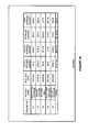
- FIG. 10 illustrates a GUI for providing a cost model in an example of the invention.
- FIG. 11 illustrates a GUI for providing a cost model in an example of the invention.
- FIG. 12 illustrates a GUI for providing a cost model in an example of the invention.
- FIG. 13 illustrates a GUI for providing a cost model in an example of the invention.
- FIG. 14 illustrates a GUI for providing an employee model in an example of the invention.
- FIG. 15 illustrates a GUI for providing an employee model in an example of the invention.
- FIG. 16 illustrates a GUI for providing an inventory model in an example of the invention.
- FIG. 17 illustrates a GUI for providing product information for the storage infrastructure in an example of the invention.
- FIG. 18 illustrates a GUI for providing product information for the storage infrastructure in an example of the invention.
- FIG. 19 illustrates a GUI for providing product information for the storage infrastructure in an example of the invention.
- FIG. 20 illustrates a GUI for providing funding information for the storage infrastructure in an example of the invention.
- FIG. 21 illustrates a GUI for providing funding information for the storage infrastructure in an example of the invention.
- FIG. 22 illustrates a GUI for providing funding information for the storage infrastructure in an example of the invention.
- FIG. 23 illustrates a GUI for providing application assignment information in an example of the invention.
- FIG. 24 illustrates a GUI for providing status and implementation information for applications and systems in an example of the invention.
- FIG. 25 illustrates a GUI for providing status and implementation information for applications and systems in an example of the invention.
- FIG. 26 illustrates a GUI for providing status and implementation information for applications and systems in an example of the invention.
- FIGS. 1-26 and the following description depict specific examples to teach those skilled in the art how to make and use the best mode of the invention. For the purpose of teaching inventive principles, some conventional aspects have been simplified or omitted. Those skilled in the art will appreciate variations from these examples that fall within the scope of the invention. Those skilled in the art will appreciate that the features described below can be combined in various ways to form multiple variations of the invention. As a result, the invention is not limited to the specific examples described below, but only by the claims and their equivalents.
- FIG. 1 illustrates communication network 100 in an example of the invention.
- Communication network 100 includes communication network elements 101 , back-office systems 102 , storage interfaces 103 , storage systems 111 - 113 , and storage management system 114 .
- Storage infrastructure 110 is a part of communication network 100 that comprises storage interfaces 103 , storage systems 111 - 113 , and storage management system 114 .
- Storage systems 111 - 113 are separated into tiers 1-N, where system 111 provides tier 1 storage, system 112 provides tier 2 storage, and system 113 provides tier N storage. As indicated on FIG. 1 , there could be many storage tiers.
- Communication network elements 101 exchange user communications 104 between network users to provide communication services.
- the communication services could include wireless, internet, telephony, video, data, or some other communications service.
- the network users maybe customers of communication network 100 or they may be other communication networks (having their own customers).
- Communication network elements 101 could include telephony switches, packet routers, wireless base stations, servers, databases, call processors, communication gateways, optical systems, and other communication equipment that are required to support the communication services provided by communication network elements 101 .
- Communication network elements 101 transfer element data 105 to back-office systems 102 .
- Element data 105 includes billing information, performance information, user content, and other data that is generated or handled by communication network elements 101 .
- Back-office systems 102 receive element data 105 from communication network elements 101 .
- Back-office systems 102 also receive other data 106 from other network systems and personnel (not shown).
- Back-office systems 102 comprise servers and computer systems that are configured to be network element management systems, customer information systems, order entry systems, communication probes, and other systems that support the communication services provided by communication network elements 101 .
- network elements 101 can include Service Control Points (SCPs) and back office systems 102 can include an SCP management system.
- SCPs Service Control Points
- Network elements 101 can include local telephone switches and back office systems 102 could include a telephony billing system.
- Network elements 101 can include a packet network and back office systems 102 could include a picture mail server.
- Network elements 101 and back office systems 102 could include numerous other systems.
- Back-office systems 102 process element data 105 and other data 106 to transfer network data 107 to storage interfaces 103 .
- Storage interfaces 103 could be Storage Area Network (SAN) switches, Network-Attached Storage (NAS) gateways, and other devices that exchange data between back-office systems 102 and storage systems 111 - 113 .
- Storage interfaces 103 transfer network data 107 to storage systems 111 - 113 .
- storage interfaces 103 direct network data 107 to the appropriate ones of storage systems 111 - 113 .
- Storage systems 111 - 113 receive and store network data 107 .
- Storage systems 111 - 113 could include disk memory systems, tape memory systems, integrated circuitry memory systems, or some other type of data storage system or media.
- storage systems 111 - 113 are tiered based on performance, where tier 1 has the best performance and tier N has the poorest performance. Typically, tier 1 is the most expensive and tier N is the least expensive. Performance can be measured based on availability. For example, tier 1 storage system 111 may have 99.999% or higher availability and exceptional performance, and tier N storage system 113 may have 97%-99.0% availability. Mid-range tiers could have availabilities in between 99.0% and 99.999%. For example, tier 2 storage system 112 could have 99.9% to 99.999% availability. Other performance measures, such as retrieval speeds or disaster recovery features, could also factor into assigning a tier value to storage systems 111 - 113 .
- Storage management system 114 is coupled to back-office systems 102 , storage interfaces 103 , and storage systems 111 - 113 by control links 115 .
- Storage management system 114 manages several aspects of storage infrastructure 110 and is described in detail below.
- FIG. 2 illustrates storage management system 114 in an example of the invention.
- Storage management system 114 includes communication interface 201 , processing system 202 , and user interface 203 .
- Processing system 202 includes storage system 204 .
- Storage system 204 stores software 205 .
- Processing system 202 is linked to communication interface 201 and user interface 203 .
- Storage management system 114 could be comprised of a programmed general-purpose computer, although those skilled in the art will appreciate that programmable or special purpose circuitry and equipment may be used.
- Storage management system 114 may use a client server architecture where operations are distributed among a server system and client devices that together comprise elements 201 - 205 .
- Communication interface 201 is coupled to control link 115 .
- Communication interface 201 could comprise a network interface card, modem, port, or some other communication device.
- Communication interface 201 may be distributed among multiple communication devices.
- Processing system 202 could comprise a computer microprocessor, logic circuit, or some other processing device.
- Processing system 202 may be distributed among multiple processing devices.
- User interface 203 includes a Graphical User Interface (GUI) display and could also comprise a keyboard, mouse, voice recognition interface, microphone and speakers, or some other type of user device.
- GUI Graphical User Interface
- Storage system 204 could comprise a disk, tape, Write Once Read Many (WORM) device, storage appliance, integrated circuit, server, or some other memory device. Storage system 204 may be distributed among multiple memory devices.
- WORM Write Once Read Many
- Processing system 202 retrieves and executes software 205 from storage system 204 .
- Software 205 may comprise an operating system, utilities, drivers, networking software, and other software typically loaded onto a general-purpose computer.
- Software 205 could comprise an application program, firmware, or some other form of machine-readable processing instructions. When executed by processing system 202 , software 205 directs processing system 202 to operate as described herein.
- storage management system 114 may be concentrated in a single system or distributed across many systems.
- storage management system 114 uses a client server architecture having a central server (i.e. processing system 202 ) and multiple client devices (i.e. user interfaces 203 ) so multiple users may simultaneously use storage management system 114 .
- FIG. 3 illustrates the operation of storage management system 114 when assigning an application data flow to a storage system tier in an example of the invention.
- the reference numbers from FIG. 3 are indicated parenthetically below.
- the tier assignment is accomplished by an operator interacting with storage management system 114 through its GUI.
- the data flow is first analyzed to determine various factors for the data flow.
- Storage management system 114 starts the process by identifying an application and by identifying the data flows for the application ( 301 ). Typically, communication network personnel will identify applications and their data flows to the operator for entry into storage management system 114 .
- An application is any functionality in communication network 100 that provides network data 107 .
- the network data 107 for the application can be separated into identifiable data flows.
- a single application can have one data flow or multiple data flows.
- the application could be a push-to-talk service that has individual data flows for billing, customer information, and performance information.
- storage management system 114 classifies the data in the data flow ( 302 ).
- the data classes include:
- Communication Path data that is associated with the set-up and operation of communication sessions for customers. For example, the routing data stored in an SCP would be classified in the communication path data class.
- Accounting data that indicates network utilization so the users may be charged for communication services. For example, call detail records for individual calls would be classified in the accounting data class.
- Fault and Alarm data that indicates problems with communication network elements 101 .
- a Synchronous Optical Network (SONET) alarm indicating an optical fiber cut would be classified in the fault and alarm data class.
- SONET Synchronous Optical Network
- Configuration data that is associated with the addition, deletion, and modification of the connections and topology of communication network 100 .
- a network architecture data flow would be classified in the configuration data class.
- Performance data that indicates network performance measurements. For example, a data flow from a probe that measures the number of packets transferred over a connection would be classified in the performance data class.
- Security data that controls access to network resources and sensitive data. For example, authorization codes that allow operations personnel to access and program Internet routers would be classified in the security data class.
- Content data that includes content that is received from or delivered to customers. For example, videos that are available for customer download would be classified in the customer content data class.
- SLA Management data class that indicates compliance with customer service agreements. For example, trouble tickets that impact a customer's service would be classified in the SLA management data class.
- storage management system 114 provides the operator with a choice of data classes for each data flow through a drop down menu or some other GUI mechanism. All data flows are classified into a consistent set of data classes. For example, FIG. 4 shows GUI 400 with table 401 for identifying applications, data flows, and data classes through operator entry. The data classes for application “A” have already been selected. After the operator positions the GUI cursor (indicated by an “X” on FIG. 4 ) over the field for entering the data class for data flow #1 of application “B”, drop down menu 402 appears with the data classes for selection. The operator may then position the cursor over the selected data class for automatic entry of the selected data class into the field.
- GUI 400 shows GUI 400 with table 401 for identifying applications, data flows, and data classes through operator entry.
- the data classes for application “A” have already been selected.
- drop down menu 402 appears with the data classes for selection. The operator may then position the cursor over the selected data class for automatic entry of the selected data class into the field.
- storage management system 114 identifies a functionality for the data flow ( 303 ).
- the functionality represents the purpose of the data flow.
- the operator is given a choice of functions through a drop down menu or some other GUI mechanism. All data flows are attributed with functionality from a consistent set of functions. Although there are typically numerous functions, a small example of functions could be:
- Function #4 Optical network alarms.
- the operator may position the GUI cursor over the function field for a given data flow, and a drop down menu box appears with the functions for selection.
- the operator may position the cursor over the selected function range for automatic entry of the selected function into the field.
- storage management system 114 For a given data flow, storage management system 114 identifies a user for the data flow ( 304 ).
- the user represents the entity in communication network 100 that needs the data storage for the data flow.
- the operator is given a choice of users through a drop down menu or some other GUI mechanism. All data flows are attributed with users from a consistent set of users. Although there are typically numerous users, a small example of users could be:
- the operator may position the GUI cursor over the user field for a given data flow, and a drop down menu box appears with the users for selection.
- the operator may position the cursor over the selected user for automatic entry of the selected user into the field.
- storage management system 114 For a given data flow, storage management system 114 attributes a value to the data flow ( 305 ). The value represents a monetary value of the data flow to communications network 100 . To attribute a value to the data flow, the operator is given a choice of monetary ranges for each data flow through a drop down menu or some other GUI mechanism. All data flows are attributed with a value from a consistent set of monetary ranges. For example, monetary ranges could be:
- Range #1 less than $1,000,000.
- the operator may position the GUI cursor over the value field for a given data flow, and a drop down menu box appears with the monetary ranges for selection.
- the operator may position the cursor over the selected monetary range for automatic entry of the selected range into the field.
- Storage management system 114 attributes a priority to the data flow ( 306 ).
- the priority represents the importance of the data flow to communication network 100 in terms of access delay, geographically diverse back-up, and disaster recovery.
- To attribute a priority to the data flow the operator is given a choice of priority levels for each data flow through a drop down menu or some other GUI mechanism. All data flows are attributed with a priority from a consistent set of priority levels. For example, priority levels could be:
- Priority Level #1 data access in less than 10 seconds with geographic diversity and disaster recovery.
- Priority Level #2 data access in less than 1 hour with geographic diversity and disaster recovery.
- Priority Level #3 data access in less than 1 day with geographic diversity and disaster recovery.
- Priority Level #4 data access in less than 1 day with geographic diversity and without disaster recovery.
- Priority Level #5 data access in less than 1 day without geographic diversity and without disaster recovery.
- the operator may position the GUI cursor over the priority field for a given data flow, and a drop down menu box appears with the priority levels for selection.
- the operator may position the cursor over the selected priority level for automatic entry of the selected level into the field.
- Storage management system 114 attributes a life-cycle to the data flow ( 307 ).
- the life-cycle represents a time period during which the data flow retains value to communications network 100 .
- To attribute a life-cycle to the data flow the operator is given a choice of time periods for each data flow through a drop down menu or some other GUI mechanism. All data flows are attributed with a life-cycle from a consistent set of time periods. For example, time periods could be:
- Life-cycle #1 less than 7 days.
- Life-cycle #2 8 days to 31 days.
- Life-cycle #4 one year to five years.
- the operator may position the GUI cursor over the life-cycle field for a given data flow, and a drop down menu box appears with the time periods for selection.
- the operator may position the cursor over the selected time period for automatic entry of the selected period into the field.
- Storage management system 114 attributes compliance requirements to the data flow ( 308 ).
- the compliance requirements indicate if the data flow needs to be kept for legal purposes.
- To attribute compliance requirements to the data flow the operator is given a choice of compliance types for each data flow through a drop down menu or some other GUI mechanism. All data flows are attributed with compliance requirements from a consistent set of compliance types. For example, compliance types could be:
- the operator may position the GUI cursor over the compliance field for a given data flow, and a drop down menu box appears with the compliance types for selection.
- the operator may position the cursor over the selected compliance type for automatic entry of the compliance requirements into the field.
- Storage management system 114 attributes inter-dependencies to the data flow ( 309 ).
- the inter-dependencies indicate other applications that are dependent on the current data flow.
- To attribute inter-dependencies to the data flow the operator is given a choice of other applications for each data flow through a drop down menu or some other GUI mechanism. All data flows are attributed with inter-dependencies from a consistent set of applications.
- the operator may position the GUI cursor over the inter-dependencies field for a given data flow, and a drop down menu box appears with the applications for selection.
- the operator may position the cursor over the selected application for automatic entry of the selected applications into the field.
- Storage management system 114 attributes performance requirements to the data flow ( 310 ).
- the performance requirements indicate any specific industry-recognized performance metrics that are required for the data flow.
- To attribute performance requirements to the data flow the operator is given a choice of industry-recognized performance metrics for each data flow through a drop down menu or some other GUI mechanism. All data flows are attributed with performance requirements from a consistent set of performance metrics.
- the operator may position the GUI cursor over the performance requirements field for a given data flow, and a drop down menu box appears with the performance metrics for selection.
- the operator may position the cursor over the selected performance metric for automatic entry of the selected requirements into the field.
- the data flow may also be associated with other factors in a similar manner. In addition, some of the factors described above could be omitted.
- storage management system 114 classifies the information represented by the data ( 311 ).
- the information classes include:
- Service path information related to service set-up and operation. For example, a data flow having routing information stored in an SCP would be classified in the service path information class.
- Revenue information related to revenue generation and support. For example, a data flow of call detail records would be classified in the revenue information.
- Operational Support information related to faults, alarms, and the status of communication network elements 101 .
- a SONET alarm indicating an optical fiber cut would be classified in the operational support information class.
- Content information related to the content that is received from or delivered to customers. For example, videos that are available for customer download would be classified in the content information class.
- Compliance and Reporting information that is required by applicable laws or regulations. For example, information required for compliance with Sarbanes-Oxley regulations would be classified in the compliance and reporting data class.
- storage management system 114 provides the operator with a choice of information classes for each data flow through a drop down menu or some other GUI mechanism. All data flows are classified into a consistent set of information classes. For example, FIG. 5 shows GUI 500 with table 501 for identifying applications, data flows, and information classes through operator entry. The information classes for application “A” have already been selected. After the operator positions the GUI cursor (indicated by an “X” on FIG. 5 ) over the field for the information class for data flow #1 of application “B”, drop down menu 502 appears with the information classes for selection. The operator may position the cursor over the selected information class for automatic entry of the selected class into the field.
- the above factors are data class, functionality, user, value, priority, life-cycle, compliance, inter-dependencies, performance, and information class.
- the factors that network management system 114 makes available for selection are controlled and consistent.
- Each factor that is available for selection has a corresponding score.
- the life-cycle factors could be scored as follows:
- the scores for all of its factors are added together to get a total score for the data flow ( 312 ).
- the individual scores Prior to summing to the total score, the individual scores may be normalized. For example, the life-cycle scores could be normalized by dividing by 5, so that all life-cycle scores are between zero and one. Prior to summing the total score, the individual scores may be weighted to emphasize or de-emphasize a given factor. For example, life-cycle scores could be multiplied by 1.5 to increase the importance of the life-cycle factor relative to the other factors, but priority scores could be multiplied by 0.5 to decrease the importance of the priority factor relative to the other factors. Once the individual scores are normalized and weighted, the normalized and weighted individual scores are summed to obtain the total score for the data flow.
- a set of key variables is assessed to determine compatibility between the data flow and the various classes of service ( 313 ).
- the classes of service are: extremely critical, mission critical, business critical, and back-office/reporting, although different classes-of-service could be used.
- the key variables are:
- Access Frequency what is the amount of access to the data that will be needed during a given time period.
- Archival and Deletion does the data need to be stored for more than a given time period and does the data need to be deleted at a given time in the future.
- Availability what percent of time must the storage system be able to provide the data.
- Business Continuity and Disaster Recovery what level of business continuity and/or disaster recovery capability is required. For example, is protection required from a simultaneous two-site failure.
- Communication Path is the data required for the establishment and operation of communication paths for customers.
- I/O Input/Output
- Data Change what percent of the data changes over a given time period.
- Policy Enforcement are there polices regarding the ability to change or delete the data.
- Disk-based Replication is disk-based back-up required for the data.
- Geographic Locations how many storage sites are required for the data.
- Load Balancing and Multi-Pathing are load balancing and/or multipathing needed to support I/O requirements for the data.
- Recovery Techniques what recovery techniques are needed. For example, is point-in-time recovery needed.
- Recovery Timeframe what is the allowed time period for data recovery.
- FIG. 6 shows GUI 600 with table 601 for identifying applications, data flows, and variable values through operator entry.
- application “A”—data flow #1 the values for access frequency and archival & deletion are respectively “HIGH” and “YES.”
- drop down menu 602 appears with the availability values for selection. The operator may position the cursor over the selected value for automatic entry of the selected availability value into the field.
- Storage management system 114 selects the class of service for the data flow based on the key variables and the total score ( 314 ). For example, once the variables are selected for the data flow, storage management system 114 compares the data flow variables against the class-of-service variables to determine which classes-of-service are suitable for the data flow. The total score is used to select from among the suitable classes of service. For example, both the extremely critical and mission critical classes-of-service may be suitable for a given data flow. The extremely critical class-of-service may be used if the data flow has a total score higher than 10 and the mission critical class-of-service may be used if the data flow has a total score of 10 or lower.
- storage management system 114 selects a storage system tier based on the selected class of service ( 315 ). Typically, each class-of-service is pre-assigned to a storage system tier. New tiers and classes-of-service may be implemented over time.
- storage management system 114 may transfer control messages indicating the selected storage system tier for the data flow to the selected tier of storage systems 111 - 113 and to storage interfaces 103 .
- storage interfaces 103 route the data flow to the selected tier, and the storage system in the selected tier stores the data and provides the various storage features available at that tier.
- storage management system 114 provides a tool for assisting the operator in assigning data flows to storage tiers.
- storage management system 114 requires the operator to consider a rigorous set of factors and variables in a consistent and disciplined manner for each data flow. The result is a high-quality and consistent approach to the assignment of data flows to data storage system tiers.
- Network management system 114 manages storage infrastructure personnel, processes, technology in some examples of the invention. To accomplish this task, network management system 114 interacts with an operator through its GUI to develop a current and future view of the personnel, processes, and technology for storage infrastructure 110 . Advantageously, network management system 114 requires the operator to apply a rigorous and detailed analysis to accurately identify the gaps between the current state and a desired future state for storage infrastructure 110 at the personnel, process, and technology levels.
- FIG. 7 illustrates GUI 700 that is provided by network management system 114 to manage personnel.
- the left column of GUI 700 lists various services that are provided by storage infrastructure personnel. These services comprise:
- Asset Management care of the storage system equipment.
- Billing charging and receiving money from storage system users.
- Capacity Management planning and control of storage system capacity.
- Configuration Management planning and control over storage system equipment configurations.
- Life-cycle management planning and control over storage and deletion time frames.
- Monitoring assessing storage system status and notifying system personnel and users of issues.
- Performance Management measuring storage system performance against SLAs.
- Procurement acquiring and installing storage system equipment.
- Provisioning establishing storage services for new applications.
- Replication copying data to a back-up storage systems.
- Reporting generating technical information about the storage system.
- GUI 700 includes several categories to prompt operator input or indicate management system output.
- the categories are:
- Primary Organization indicates the main organization that provides the service.
- Targeted Hours indicates a desired number of hours that the primary organization should spend providing the service in a future time period. (hours in the next month for example).
- Targeted Hours indicates a desired number of hours that the secondary organization should spend providing the service in a future time period. (hours in the next month for example).
- Personnel Gap indicates the difference between the current hours and the targeted hours for the primary and secondary organizations.
- storage management system 114 obtains a yes or no response from the operator in the Currently Delivered column on GUI 700 .
- storage management system 114 uses GUI 700 to obtain the primary organization that currently provides the service from the operator.
- GUI 700 also obtains any secondary organizations that currently provide the service.
- the operator may position the GUI cursor over the primary organization field or secondary organization field for a given service, and a drop down menu box appears with the various organizations for selection. The operator may position the cursor over the selected organization for automatic entry of the selected organization into the field.
- storage management system 114 uses GUI 700 to obtain the current hours that the primary organization and any secondary organizations use to provide the service. For each service, storage management system 114 uses GUI 700 to obtain the targeted hours that the primary organization and any secondary organizations should use to provide the service.
- network management system 114 On a per-service basis, network management system 114 totals the current hours for the primary and secondary organizations and totals the targeted hours for the primary and secondary organizations. On a per-service basis, network management system 114 subtracts the total of targeted hours from the total for current hours to identify the personnel gap for that service. Network management system 114 automatically indicates the personnel gaps on a per-service basis in the right column of GUI 700 .
- network management system 114 For all services, network management system 114 totals the current hours for the primary and secondary organizations and totals the targeted hours for the primary and secondary organizations. Network management system 114 subtracts the total of targeted hours (for all services) from the total for current hours (for all services) to identify the personnel gap for all services. Network management system 114 automatically indicates the personnel gap for all services at the right in the bottom row of GUI 700 .
- FIG. 8 illustrates GM 800 that is provided by network management system 114 to manage process.
- the left column of GM 800 lists various service that are provided by storage infrastructure personnel and described above for FIG. 7 .
- the top row of GUI 800 includes several categories to prompt operator input or indicate management system output. The categories are:
- Primary Process Owner indicates the main organization that provides the service.
- Secondary Process Owner indicates any support organization that helps provide the service.
- Primary Process User indicates the main organization that uses the service.
- Targeted Maturity Level indicates the desired complexity of the service.
- Process Gaps indicates the difference between the current maturity level and the targeted maturity level for each service.
- GUI 800 For each service, storage management system 114 obtains a yes or no response from the operator in the Documented Process column on GUI 800 . For each service, storage management system 114 uses GUI 800 to obtain the primary organization that currently provides the service from the operator. GUI 800 obtains any secondary organizations that currently provide the service. Likewise, GUI 800 also obtains primary and secondary process users from the operator. Like the GUI operations depicted above, the operator may position the GUI cursor over a process owner or user field for a given service, and a drop down menu box appears with the various organizations for selection. The operator may position the cursor over the selected organization for automatic entry of the selected organization into the field.
- storage management system 114 uses GUI 800 to obtain the current maturity level of the process and the desired maturity level for the process.
- GUI 800 To each service, storage management system 114 uses GUI 800 to obtain the current maturity level of the process and the desired maturity level for the process.
- the operator may position the GUI cursor over a maturity level field for a given service, and a drop down menu box appears with the various maturity levels for selection. The operator may position the cursor over the selected level for automatic entry of the selected maturity level into the field.
- a maturity index could be defined from one to ten where an index of one indicates minimum complexity and an index of ten indicates maximum complexity.
- the various indexes could be differentiated by reference to industry standards, technologies, or other applicable descriptions.
- a maturity index could be used to indicate the current maturity level of the process for the service.
- network management system 114 compares the current and targeted maturity levels to determine the difference. If a maturity index is used, the numerical difference between the two indexes could be used. Network management system 114 automatically indicates the maturity difference on a per-service basis in the right column of GUI 800 .
- FIG. 9 illustrates GUI 900 that is provided by network management system 114 to manage technology.
- the left column of GUI 900 lists various services that are provided by storage infrastructure personnel and described above for FIG. 7 .
- the top row of GUI 900 includes several categories to prompt operator input or indicate management system output. The categories are:
- Gaps indicates the personnel and process gaps from GUIs 700 and 800 .
- Hardware to be purchased indicates additional hardware to be purchased and installed.
- Software to be purchased indicates additional software to be purchased and installed.
- External Service to be purchased indicates additional external resources to be purchased.
- storage management system 114 obtains the existing hardware, software, and external services from the operator in the applicable columns on GUI 900 .
- storage management system 114 indicates the personnel and process gaps developed in GUI 700 and GUI 800 .
- the operator may position the GUI cursor over a given field, and a drop down menu box appears with the various items for selection. The operator may position the cursor over the selection for automatic entry of the selection into the field.
- storage management system 114 uses GUI 900 to obtain from the operator the hardware, software, and external services to be purchased and to obtain the time of the purchase.
- the operator can view the existing technology (hardware, software, external services) used to deliver the service, and the operator can also view the personnel and process gaps for the service.
- network management system 114 enables purchasing decisions to be made that close these gaps.
- technology is used to reduce personnel gaps and to improve process maturity.
- Storage infrastructure 110 includes numerous storage systems 111 - 113 that include disks, tape, and other memory devices and media.
- Storage infrastructure 110 includes numerous computer systems, such as servers, that form a part of storage interfaces 103 and provide I/O to the storage systems 111 - 113 .
- these computer systems have internal storage devices, such as internal disks, that also form a part of storage systems 111 - 113 .
- storage infrastructure 110 requires personnel, communication networking, operating environments, and other numerous other resources.
- Network management system 114 manages costs associated with storage infrastructure 110 in some examples of the invention. To accomplish this task, network management system 114 interacts with an operator through its GUI to develop individual cost models for the individual computer systems and storage systems that comprise storage infrastructure 110 . For each computer system and storage system, network management system 114 processes the model to provide a cost per unit of storage, such as dollars per Gigabit (GB). Advantageously, network management system 114 allows for direct comparison of the costs associated with the various computer systems and storage systems to improve the management of storage infrastructure 110 .
- GB Gigabit
- FIGS. 10-13 illustrate GUI 1000 that is provided by network management system 114 to manage cost.
- the left column of GUI 1000 lists various cost parameters related to employees, servers, internal disks, external disks, tape, networking, software, additional equipment, environment, outages, growth, and finance.
- the top row lists various computer systems and storage systems. The number of computer and storage systems could be much larger and has been restricted for clarity.
- GUI 1000 may directly enter data for a given parameter of a given system.
- the operator may position the GUI cursor over a data field, and a drop down menu box appears with the various values for selection. The operator may position the cursor over the selected value for automatic entry of the selected value into the data field.
- network management system 114 may retrieve the value from another system or calculate the value from other inputs.
- GUI 1000 is filled with information on a per computer system or per storage system basis. Network management system 114 then processes that information to provide comparative costs and comments for the computer and storage systems.
- the cost parameters for employee costs are:
- FTEs Number of primary Full Time Employees
- Number of secondary FTEs the number of FTEs whose primary task is not associated with a given storage or computer system, but who are secondarily associated with a given storage or computer system.
- Additional FTE costs extra costs for FTEs not captured above, such as training and retention costs.
- Service contract costs annual costs for personnel service contracts.
- the parameters for computer system (server) costs are:
- Number of servers the total number of servers.
- Average cost of medium servers the cost of servers with 2-3 CPUs.
- Average cost of large servers the cost of servers with 4 or more CPUs.
- % of infrastructure comprised of small servers the ratio of small servers to all servers as indicated by relative number of CPUs, transactions per second, number of servers, or some other metric.
- % of infrastructure comprised of medium servers the ratio of medium servers to all servers as indicated by relative number of CPUs, transactions per second, number of servers, or some other metric.
- % of infrastructure comprised of large servers the ratio of large servers to all servers as indicated by relative number of CPUs, transactions per second, number of servers, or some other metric.
- Number of years for server amortization the number used by accounting for tax purposes.
- % of server costs not for internal disks the ratio of server costs that are not internal disk costs, such as software and accessory costs, to the total server costs.
- Total cost of internal disks the total cost for all internal disks.
- Total data capacity of internal disks the total data capacity of all internal disks.
- Purchased but uninstalled capacity the data capacity for internal disks that are paid for but not yet available in the storage system.
- the cost parameters for external disk costs are:
- Total data capacity of external disks the total data capacity of all external disks.
- Purchased but uninstalled capacity the data capacity for external disks that are paid for but not yet installed.
- the cost parameters for tape costs are:
- % of tape capacity in use the amount of data on tape divided by the total storage capacity of tape.
- Number of tape drives the total number of tape drives.
- Number of tape libraries the total number of multiple tape drive systems (tape libraries).
- Average capacity of tape cartridges the storage capacity of a tape cartridge.
- Number of tape cartridges the number of tape cartridges.
- the cost parameters for networking costs are:
- Total network costs the cost of the communication network serving the storage network
- % of network used for storage the amount of bandwidth used by the given system divided by the total bandwidth of the communication network.
- SLAs Restoration meeting Service Level Agreements
- Networking cost per unit storage (the total cost of the communication network) ⁇ (the % of the communication network used by the system for storage) ⁇ (the storage units provided by the system).
- the cost parameters for software costs are:
- Average annual cost of software for disks the yearly software cost for disks.
- Average annual cost of software for tape the yearly software cost for tape.
- SAN Storage Area Network
- the cost parameters for environmental costs are:
- the cost parameters for outage costs are:
- Average availability the % of time that data is available from the system.
- Average time that the availability covers the time in hours, days, weeks during which the availability is provided.
- Availability being met indicates if the promised availability was delivered by the system.
- Hourly revenue loss for scheduled outages loss revenue (i.e. sales) per hour for scheduled outages.
- Average number of users affected by unscheduled outages the typical number of users impacted by unscheduled outages.
- Average number of users affected by scheduled outages the typical number of users impacted by scheduled outages.
- Outage penalties cost penalties (i.e. in SLAs) attributed to outages.
- Average hourly cost of outages the average lost revenue and productivity per hour for scheduled and unscheduled outages.
- the cost parameters for growth costs are:
- Number of years for business case the number of years for a return on investment in the business case.
- Inflation rate estimatemate of the annual inflation rate.
- Network management system 114 processes the above information to indicate total costs per unit storage ($/GB) for each computer system and server system on GUI 1000 .
- Network management system 114 also processes the above information to indicate comments for each computer system and server system on GUI 1000 .
- network management system 114 can calculate cost per unit of storage (GB) per system as follows.
- Cost per unit storage cost of computer or storage system ⁇ the data capacity of the computer or storage system.
- Network management system 114 can calculate the various data capacities on a per system basis as follows.
- Storage capacity total capacity of external disks+total capacity of internal disks+total capacity of tape.
- Network management system 114 can calculate the various costs on a per system basis as follows.
- Total system cost FTE costs+server costs+internal disk costs+external disk costs+tape costs+network costs+software costs+additional equipment costs+environmental costs+outage costs+growth costs;
- FTE costs (number of primary FTEs ⁇ primary FTE cost)+(number of secondary FTEs ⁇ secondary FTE cost)+service contract costs.
- Server costs (number of servers ⁇ % of small servers ⁇ average cost of small servers)+(number of servers ⁇ % of medium servers ⁇ average cost of medium servers)+(number of servers ⁇ % of large servers ⁇ average cost of large servers).
- External disk costs (total GB of external disks ⁇ cost per GB for external disks)+disk configuration fees+disk maintenance fees.
- Tape costs tape hardware cost+tape vaulting cost+tape media cost.
- Network costs total network cost ⁇ % of network used for storage.
- Environmental cost environmental cost+miscellaneous cost.
- Outage cost average hourly cost of outages ⁇ annual hours per year of outages.
- Growth costs (% disk growth ⁇ total disk capacity ⁇ average cost of disks)+(% server growth ⁇ total servers ⁇ average cost of server)+(% tape growth ⁇ total tape capacity ⁇ average cost of tape hardware, media, and vaulting)+(% FTE growth ⁇ total FTEs ⁇ average burdened cost of FTE).
- network management system 114 provides a detailed cost model that is broken down by computer and storage system. By using the cost per gigabyte calculations, the operator may directly compare the cost effectiveness of the various systems.
- Storage infrastructure 110 includes numerous storage systems 111 - 113 that include disks, tape, and other memory devices and media.
- Storage infrastructure 110 includes numerous computer systems, such as servers, that form a part of storage interfaces 103 and provide I/O to the storage systems 111 - 113 .
- Storage infrastructure 110 requires employees—referred to as Full Time Employees (FTEs)—to plan, design, and operate the storage infrastructure. This entails planning, designing, and operating the computer systems and storage systems that comprise the storage infrastructure. The FTEs execute various processes to perform these tasks.
- FTEs Full Time Employees
- Network management system 114 manages the FTEs associated with storage infrastructure 110 in some examples of the invention. To accomplish this task, network management system 114 interacts with an operator through its GUI to develop individual FTE models for the individual computer systems and storage systems that comprise storage infrastructure 110 . In addition, network management system 114 interacts with the operator through the GUI to develop individual FTE models for the planning, design, and operation of storage infrastructure 110 .
- the models indicate FTE use at the process level as correlated to the computer systems, storage systems, and activities related to planning, design, and operation.
- FIGS. 14-15 illustrate GUI 1400 that is provided by network management system 114 to manage FTEs.
- the left column of GUI 1400 lists various processes performed by the FTEs.
- the top row lists the computer and storage systems although the number depicted is restricted for clarity, numerous other computer and storage system could be added to the top row.
- Beneath each system are columns for planning, design, operations, and other activities.
- Planning activities relate to the development of a strategic plan for the infrastructure.
- Design activities relate to the development of detailed designs to implement the infrastructure plan.
- Operational activities relate to running the infrastructure as implemented.
- the other column is for activities that are not primarily related to planning, design, or operations.
- the percent of FTE time that is spent on a given activity in the performance of a given process for a given system is entered into the corresponding field.
- GUI 1400 is filled with information on a per process, per system, and per activity basis.
- Network management system 110 then processes the information to provide a model that compares FTE usage across systems and activities at the process level.
- the processes in the left column are: satisfy customer relationships, provide management system, manage business value, realize solutions, deploy solutions, deliver operational services, support network services, and manage network assets and infrastructure.
- Each of these processes has a set of sub-processes.
- the processes and their sub-process are described as follows:
- SLAs Service Level Agreements
- Manage customer satisfaction interact with the customer to detect problems and verify customer satisfaction.
- Provide Management System developer a management organization and processes.
- Manage Business Value developer storage infrastructure to provide storage services on a cost-benefit basis.
- Storage architecture develop an infrastructure plan to provide the storage services according to the storage strategy.
- Monitor storage services analyze on-going return on investment for the storage services.
- Design solutions develop solutions to requirements and identify services to provide solutions.
- Test solutions verify solutions are effective.
- Deploy Solutions configure the storage infrastructure to provide the customer solutions.
- infrastructure change management policies specifications specifyify standards for changing infrastructure configuration.
- Plan deployment for infrastructure change developer a deployment plan for the infrastructure change.
- Service delivery plan develop an operational plan for the infrastructure.
- Allocate storage resources provide resources to execute the operational plan.
- Manage configuration information provide a secure configuration data repository.
- Manage facilities provide appropriate operating environment.
- Manage Network Assets and Infrastructure provide executive management for the infrastructure.
- Manage security provide a secure environment for the infrastructure.
- GUI 1400 lists the percent of FTE time that is spent on various processes and sub-processes as correlated to various activities for various systems.
- Network management system 114 processes the information on GUI 1400 to provide various totals. Note that process sub-total rows provide sub-totals for each process, and the bottom row provides totals for all processes. The right column provides totals for each process and sub-process for all systems and activities.
- network management system 114 provides a direct comparison of how FTE time is spent on various processes and systems.
- Storage infrastructure 110 includes numerous storage systems 111 - 113 that include disks, tape, and other memory devices and media.
- Storage infrastructure 110 includes numerous computer systems, such as servers, that form a part of storage interfaces 103 and provide I/O to the storage systems 111 - 113 .
- storage infrastructure 110 includes numerous devices and systems that are comprised various vendor products. The vendor products represent an asset inventory that must be managed.
- Network management system 114 manages the inventory that comprises storage infrastructure 110 in some examples of the invention. To accomplish this task, network management system 114 interacts with an operator through its GUI to develop an inventory model for storage infrastructure 110 .
- the inventory model indicates inventory assets and characteristics of interest.
- the assets are storage systems, such as disk and tape systems.
- FIG. 16 illustrates GUI 1600 that is provided by network management system 114 to manage inventory.
- the top row left column of GUI 1600 lists various inventory assets that comprise storage infrastructure 110 .
- the left column lists various characteristics for each asset. The asset characteristics are indicated below.
- Vendor indicates the supplier of the product.
- Location identifies the physical site having the asset.
- Storage Type identifies the asset by storage type, such as network attached storage, storage area network, tape, etc.
- Number of servers the number of servers connected to the asset.
- Number of connections the number of connections from the servers to the asset.
- Owned or leased is the asset owned or leased.
- % depreciated (if owned) the age of the asset divided by the amortization term for the asset.
- Acquisition data the date the asset was acquired.
- Depreciation term the amortization period for the asset.
- Maintenance contract is there a maintenance contract.
- Installed capacity installed storage capacity of the asset.
- Hot spare capacity hot spare capacity available from the asset.
- Available capacity storage capacity available from the asset.
- Utilized capacity % of available storage capacity in use in the asset.
- RAID level the industry standard RAID level of the asset.
- GUI 1600 is filled with information on a per asset basis.
- Network management system 110 then processes the information to provide a model that compares assets in terms of maximum, installed, available, and in-use storage capacities.
- FIGS. 17-19 illustrate GUI 1700 that is provided by network management system 114 to manage inventory.
- GUI 1700 depicts a block diagram of storage infrastructure 110 that includes storage interfaces 103 , tiered storage systems 111 - 113 , and network 120 .
- the GUI operator may select one of these elements, such as by clicking the element with a mouse, and GUI 1700 depicts the selected element in further detail. This operator selection process can continue until desired product or status information is provided.
- GUI 1700 may select tier 2 storage system 112 as indicated by the “X” mark on FIG. 17 .
- GUI 1700 depicts tier 2 storage system 112 in further detail as shown in FIG. 18 .
- GUI 1700 shows tier 2 storage system 112 as having computer systems 1-N and disk systems 1-N.
- the GUI operator may then select disk system 1 as indicated by the “X” mark on FIG. 18 .
- GUI 1700 depicts disk system 1 in further detail as shown in FIG. 19 .
- GUI 1700 shows disk system 2 as having disks 1-N.
- the GUI operator may finally select disk 2 as indicated by the “X” mark on FIG. 19 .
- GUI 1700 depicts product and status information for disk 2 in an information box as shown in FIG. 19 .
- the information box indicates information for disk 2 including: product ID, vendor, location, installation date, total capacity, and unused capacity. Note that other information, such as that indicated on FIG. 16 , could be included in information box 1900 .
- GUI 1700 could be used to obtain product information for a storage switch in storage interfaces 103 .
- GUI 1700 could be used to obtain product information for a network link in communication network 120 .
- Network management system 114 manages storage infrastructure funding in some examples of the invention. To accomplish this task, network management system 114 interacts with an operator through its GUI to provide project funding and scheduling information. FIGS. 20-22 illustrate GUI 2000 that is provided by network management system 114 to manage funding.
- GUI 2000 lists various projects by ID and name.
- the third column lists the roll-out date for the project, where the roll-out date indicates when project funding must be available.
- the fourth column lists the total budget for each project. This project information could be entered by the operator or retrieved from other management systems.
- Network management system 114 processes the project information to determine the preliminary storage budget for the project, savings provided by storage infrastructure 110 , and a final storage budget. To determine this information, network management system 114 can apply various rules to the project data.
- the preliminary storage budget could be a percentage of the total budget, where the percentage could be based on the total budget cost as follows.
- the preliminary storage budget would be the total budget multiplied by the appropriate percentage. Note that other techniques or factors could be used. For example, the percentages could be further broken down based on the type of project, the organization handling the project, or some other factor.
- the savings provided by storage infrastructure 110 can be a percentage of the preliminary storage budget, where the percentage could be based on the preliminary storage budget as follows.
- the storage savings would be the preliminary storage budget multiplied by the appropriate percentage. Note that other techniques or factors could be used. For example, the percentages could be further broken down based on the type of project, the organization handling the project, or some other factor.
- the final storage budget is the preliminary storage budget less the savings.
- the budget numbers could be further broken down into subject matter buckets.
- the final storage budget for a project could be separated into a hardware budget, software budget, and services budget by using a rule set.
- the final storage budget could be allocated as follows: 60% of the final storage budget is for hardware, 20% is for software, and 20% is for services.
- FIG. 21 shows another version of GUI 2000 .
- GUI 2000 now provides a future forecast of storage funding based on the data of FIG. 20 .
- the vertical axis represents storage funding and the horizontal axis represents time from the present in months.
- the final storage budget for each project is added to the total storage budget as of the roll-out date.
- the present time for GUI 2000 is Jan. 1, 2006 so the $450 K final storage budget for project X1 appears after the first month.
- the $1M final storage budget for project X3 and the $2.4 M final storage budget for projects X3 and X4 appear after the fifth month.
- FIG. 22 shows another version of GUI 2000 .
- GUI 2000 now provides a graph of actual storage investment and savings based on actual spending and savings data. The actual numbers could be retrieved from an accounting system.
- the vertical axis represents monetary amounts for actual storage investment and savings.
- the horizontal axis represents time periods in the past broken down by quarter, although other time periods such as months could be used.
- bar graphs indicate investment in the quarter, savings in the quarter, total investment for the specified period, and total savings for the specified period. From FIG. 22 , it can be seen that the total investment and savings bars grow at the rate of quarterly investment and savings.
- the operator may select which version of GUI 2000 ( FIG. 21 , 22 , or 23 ) to view through the use of selection buttons, page tabs, or some other GUI technique.
- GUI 2000 FIG. 21 , 22 , or 23
- the operator is automatically provided with a financial picture of the storage infrastructure that indicates past, present, and future investment and savings. This information is of critical importance when making decisions on funding and timing of new storage projects and when evaluating existing projects.
- Network management system 114 manages storage infrastructure application status in some examples of the invention. To accomplish this task, network management system 114 interacts with an operator through its GUI to provide application status and implementation information.
- FIG. 23 illustrates GUI 2300 that is provided by network management system 114 to manage application status.
- various applications 1-N and their respective data flows 1-N are shown at the top of GUI 2300 .
- the various information classes, service classes, and storage system tiers are shown under the applications on GUI 2300 .
- GUI 2300 graphically illustrates the information class, service class, and storage tier for the selected data flow.
- GUI 2300 uses arrows to illustrate that the selected data flow has been assigned to information class #2, service class #3, and storage tier #2. Note that color coding or other graphical techniques could be used to simultaneously illustrate these assignments for multiple data flows.
- FIGS. 24-26 illustrates GUI 2400 that is provided by network management system 114 to manage application implementation information.
- various applications 1-N and their respective data flows 1-N are shown at the top of GUI 2400 .
- the various storage interfaces and storage tiers are shown under the applications on GUI 2400 .
- the top of GUI 2400 also has selection buttons for various views that show the various stages of implementation. The views are for planned implementations, implementations under test, and operational implementations.
- GUI 2400 graphically illustrates the applications, data flows, storage interfaces and storage tiers that are planned but not yet tested or operational.
- a dashed line is used to indicate that applications 2-N (and their data flows), storage interfaces 3-N, and storage tier N are planned but not yet tested or operational.
- GUI 2400 graphically illustrates the applications, data flows, storage interfaces, and storage tiers that are under test but not yet operational.
- a dashed line is used to indicate that storage interface 2 and storage tiers 2-3 are currently under test.
- GUI 2400 graphically illustrates the applications, data flows, storage interfaces and storage tiers that are operational—meaning that planning and testing is complete.
- a dashed line is used to indicate that application #1, storage interface #1, and storage tier #1 are currently operational.
- color coding or other graphical techniques could be used to simultaneously illustrate the implementations that are planned, under test, and operational.
- Network management system 114 could retrieve the current status of the various applications and systems from another system, or the operator could enter the status for each application and system.
- network management system 114 enables the GUI operator to obtain a quick but effective view of the planning and development of storage infrastructure 110 .
- FIGS. 1-26 and the preceding text have described storage management system 114 that manages storage infrastructure 110 in communication network 100 .
- Storage management system 114 assigns individual data flows to individual storage systems 111 - 113 based on a rigorous and robust analysis.
- Storage management system 114 also displays data storage infrastructure 110 and various related information.
- Storage management system 114 displays infrastructure models, implementation status, and funding status for data storage infrastructure 110 .
- the models include a cost model, an employee model, and an inventory model.
- the implementation status indicates if systems in data storage infrastructure 110 are planned, under test, or operational.
- the funding status indicates actual past funding and forecasted future funding.
- Storage management system 114 also determines gaps between the current storage infrastructure and a target storage infrastructure.
- the gaps include a personnel gap, a hardware gap, and a software gap.
- storage management system 114 provides a powerful management tool for storage infrastructures in communication networks.
- Storage management system 114 tracks and models current infrastructure status, identifies gaps for infrastructure growth, analyzes infrastructure funding, and assigns new data flows to the proper storage system and service level.
- storage management system 114 provides a comprehensive set of capabilities that address numerous problems facing communication networks that require complex storage infrastructures.
Abstract
Description
| Extremely | Business | Back-office, | ||
| Variable | Critical | Mission Critical | Critical | Reporting |
| Access | Very High | Very High | High | Medium |
| frequency | ||||
| Archival and | Yes | Yes | Yes | Yes |
| deletion | ||||
| Availability | 99.999% | 99.990% to | 99.90% to | 97.0% to 99.0% |
| 99.90% | 99.0% | |||
| Back-up | Yes | Yes | Yes | Yes |
| Business | Yes | Yes | No | No |
| continuity and | ||||
| disaster | ||||
| recovery | ||||
| Com. path | Yes | No | No | No |
| Compliance | No | No | No | Yes |
| Connectivity | Multiple | Multiple | Multiple | SLA specific |
| Data loss | No | Recoverable up | Recoverable up | Application |
| to a point in | to a point in | specific | ||
| time | time | |||
| Data migration | Yes | Yes | Yes | Yes |
| Data change | Very high | Very high | Very high | High |
| Policy | Yes | Yes | Yes | Yes |
| enforcement | ||||
| Disk-based | Yes | Yes, for | No | No |
| replication | selected data | |||
| Geographic | Multiple | Multiple for | No | No |
| locations | selected data | |||
| Business | Yes | Yes | No | No |
| impact | ||||
| Load balancing | Yes | Yes | Yes | SLA specific |
| and multi- | ||||
| pathing | ||||
| Monitoring | 27 × 7 × 365 | 27 × 7 × 365 | 27 × 7 × 365 | Periodic alert |
| requirements | immediate | immediate | immediate | during business |
| alert | alert | alert | hours | |
| Operational | High | High | High | High |
| flexibility | ||||
| Performance | Exceptional | Exceptional | High | Medium |
| Provisioning | 1-3 days | 1-3 days | 1-5 days | 5-7 days |
| Recovery | Point-in-time, | Point-in-time, | Point-in-time | Point-in-time |
| techniques | Multiple geo- | Multiple geo- | ||
| graphical sites, | graphical sites, | |||
| synchronous & | synchronous & | |||
| asynchronous | asynchronous | |||
| Recovery time- | 10-59 minutes | 1-12 hours | 12-48 hours | 2-5 business |
| frame | days | |||
| Response time | Very high | Very high | High | High |
| Service loss | No | Brief | Yes | Yes |
| TOTAL | STORAGE BUDGET | ||
| BUDGET | PERCENTAGE | ||
| 0 to $500K | 20% | ||
| $500K to |
25% | ||
| $1 M to $3 M | 30% | ||
| $3 M to $5 M | 35% | ||
| $5 M to $10 M | 40% | ||
| PRELIMINARY | |||
| STORAGE | SAVINGS | ||
| BUDGET | PERCENTAGE | ||
| 0 to $500 |
5% | ||
| $500K to |
10% | ||
| $1 M to $3 M | 15% | ||
| $3 M to $5 M | 20% | ||
| $5 M to $10 |
25% | ||
Claims (20)
Priority Applications (1)
| Application Number | Priority Date | Filing Date | Title |
|---|---|---|---|
| US11/335,314 US7801973B1 (en) | 2006-01-19 | 2006-01-19 | Classification of information in data flows in a data storage infrastructure for a communication network |
Applications Claiming Priority (1)
| Application Number | Priority Date | Filing Date | Title |
|---|---|---|---|
| US11/335,314 US7801973B1 (en) | 2006-01-19 | 2006-01-19 | Classification of information in data flows in a data storage infrastructure for a communication network |
Publications (1)
| Publication Number | Publication Date |
|---|---|
| US7801973B1 true US7801973B1 (en) | 2010-09-21 |
Family
ID=42734015
Family Applications (1)
| Application Number | Title | Priority Date | Filing Date |
|---|---|---|---|
| US11/335,314 Active 2028-03-28 US7801973B1 (en) | 2006-01-19 | 2006-01-19 | Classification of information in data flows in a data storage infrastructure for a communication network |
Country Status (1)
| Country | Link |
|---|---|
| US (1) | US7801973B1 (en) |
Cited By (5)
| Publication number | Priority date | Publication date | Assignee | Title |
|---|---|---|---|---|
| US20110087657A1 (en) * | 2006-07-28 | 2011-04-14 | Diskeeper Corporation | Assigning data for storage based on speed with which data may be retrieved |
| WO2012078575A1 (en) * | 2010-12-06 | 2012-06-14 | Qualcomm Atheros, Inc. | Technique for managing traffic at a router |
| US20140325149A1 (en) * | 2011-10-12 | 2014-10-30 | Tata Consultancy Services Limited | Method and system for consolidating a plurality of heterogeneous storage systems in a data center |
| US20150106471A1 (en) * | 2012-08-02 | 2015-04-16 | Huawei Technologies Co., Ltd. | Data Processing Method, Router, and NDN System |
| US20220188004A1 (en) * | 2020-12-15 | 2022-06-16 | International Business Machines Corporation | Transferring an operating image into a multi-tenant environment |
Citations (111)
| Publication number | Priority date | Publication date | Assignee | Title |
|---|---|---|---|---|
| US5287500A (en) * | 1991-06-03 | 1994-02-15 | Digital Equipment Corporation | System for allocating storage spaces based upon required and optional service attributes having assigned piorities |
| JPH07192006A (en) * | 1993-12-27 | 1995-07-28 | Toshiba Corp | Data storage communication system |
| US5500934A (en) | 1991-09-04 | 1996-03-19 | International Business Machines Corporation | Display and control system for configuring and monitoring a complex system |
| US5765140A (en) | 1995-11-17 | 1998-06-09 | Mci Corporation | Dynamic project management system |
| US5958012A (en) | 1996-07-18 | 1999-09-28 | Computer Associates International, Inc. | Network management system using virtual reality techniques to display and simulate navigation to network components |
| US6031528A (en) | 1996-11-25 | 2000-02-29 | Intel Corporation | User based graphical computer network diagnostic tool |
| US6046980A (en) | 1996-12-09 | 2000-04-04 | Packeteer, Inc. | System for managing flow bandwidth utilization at network, transport and application layers in store and forward network |
| US6086618A (en) | 1998-01-26 | 2000-07-11 | Microsoft Corporation | Method and computer program product for estimating total resource usage requirements of a server application in a hypothetical user configuration |
| US6088816A (en) | 1997-10-01 | 2000-07-11 | Micron Electronics, Inc. | Method of displaying system status |
| US6128016A (en) | 1996-12-20 | 2000-10-03 | Nec Corporation | Graphic user interface for managing a server system |
| US6173311B1 (en) | 1997-02-13 | 2001-01-09 | Pointcast, Inc. | Apparatus, method and article of manufacture for servicing client requests on a network |
| US20010004520A1 (en) | 1999-12-16 | 2001-06-21 | Tazu Nomoto | Method of production planning |
| US6253240B1 (en) | 1997-10-31 | 2001-06-26 | International Business Machines Corporation | Method for producing a coherent view of storage network by a storage network manager using data storage device configuration obtained from data storage devices |
| US6345239B1 (en) | 1999-08-31 | 2002-02-05 | Accenture Llp | Remote demonstration of business capabilities in an e-commerce environment |
| US6346954B1 (en) | 1998-12-21 | 2002-02-12 | International Business Machines Corporation | User interface for configuring and managing a multi-drive data storage system |
| US6370573B1 (en) | 1999-08-31 | 2002-04-09 | Accenture Llp | System, method and article of manufacture for managing an environment of a development architecture framework |
| US6405364B1 (en) | 1999-08-31 | 2002-06-11 | Accenture Llp | Building techniques in a development architecture framework |
| US20020087635A1 (en) | 2000-09-19 | 2002-07-04 | Takehito Yamaguchi | Business machine network terminal and business machine network information management system |
| US6427132B1 (en) | 1999-08-31 | 2002-07-30 | Accenture Llp | System, method and article of manufacture for demonstrating E-commerce capabilities via a simulation on a network |
| US6434568B1 (en) | 1999-08-31 | 2002-08-13 | Accenture Llp | Information services patterns in a netcentric environment |
| US20020124086A1 (en) * | 2000-11-24 | 2002-09-05 | Mar Aaron S. | Policy change characterization method and apparatus |
| US6460082B1 (en) | 1999-06-17 | 2002-10-01 | International Business Machines Corporation | Management of service-oriented resources across heterogeneous media servers using homogenous service units and service signatures to configure the media servers |
| US20020152305A1 (en) | 2000-03-03 | 2002-10-17 | Jackson Gregory J. | Systems and methods for resource utilization analysis in information management environments |
| US20020152181A1 (en) | 2001-04-16 | 2002-10-17 | Hitachi Ltd. | Service method of a rental storage and a rental storage system |
| US20020165961A1 (en) | 2001-04-19 | 2002-11-07 | Everdell Peter B. | Network device including dedicated resources control plane |
| US20020169658A1 (en) | 2001-03-08 | 2002-11-14 | Adler Richard M. | System and method for modeling and analyzing strategic business decisions |
| US20020194369A1 (en) | 2001-03-20 | 2002-12-19 | Worldcom, Inc. | Policy-based synchronization of per-class resources between routers in a data network |
| US20030033226A1 (en) | 2001-08-13 | 2003-02-13 | Anderson Eric S. | Web-based time and activity tracking systems and methods |
| US20030037187A1 (en) | 2001-08-14 | 2003-02-20 | Hinton Walter H. | Method and apparatus for data storage information gathering |
| US20030055735A1 (en) | 2000-04-25 | 2003-03-20 | Cameron Richard N. | Method and system for a wireless universal mobile product interface |
| US6538669B1 (en) | 1999-07-15 | 2003-03-25 | Dell Products L.P. | Graphical user interface for configuration of a storage system |
| US20030146929A1 (en) | 2001-10-05 | 2003-08-07 | Baldwin Duane Mark | User interface architecture for storage area network |
| US6611867B1 (en) | 1999-08-31 | 2003-08-26 | Accenture Llp | System, method and article of manufacture for implementing a hybrid network |
| US20030172145A1 (en) | 2002-03-11 | 2003-09-11 | Nguyen John V. | System and method for designing, developing and implementing internet service provider architectures |
| US6636250B1 (en) | 2000-04-12 | 2003-10-21 | Emc Corp | Methods and apparatus for presenting information to a user of a computer system |
| US20030225801A1 (en) | 2002-05-31 | 2003-12-04 | Devarakonda Murthy V. | Method, system, and program for a policy based storage manager |
| US6670973B1 (en) | 1999-06-29 | 2003-12-30 | Electronic Data Systems Corporation | System and method for representing the information technology infrastructure of an organization |
| US6684191B1 (en) | 1999-11-22 | 2004-01-27 | International Business Machines Corporation | System and method for assessing a procurement and accounts payable system |
| US20040030563A1 (en) | 2002-08-09 | 2004-02-12 | Porcari John C. | Portal value indicator framework and tool |
| US20040039891A1 (en) | 2001-08-31 | 2004-02-26 | Arkivio, Inc. | Optimizing storage capacity utilization based upon data storage costs |
| US20040054545A1 (en) | 2002-09-13 | 2004-03-18 | Electronic Data Systems Corporation | System and method for managing innovation capabilities of an organization |
| US20040064349A1 (en) | 2002-09-30 | 2004-04-01 | Humenansky Brian S. | Deploying multiple enterprise planning models across clusters of application servers |
| US6721795B1 (en) | 1999-04-26 | 2004-04-13 | America Online, Inc. | Data transfer server |
| US20040093289A1 (en) | 2002-11-07 | 2004-05-13 | International Business Machines Corporation | Location based services anonymous session tracking and anonymous information aggregation |
| US20040136379A1 (en) | 2001-03-13 | 2004-07-15 | Liao Raymond R | Method and apparatus for allocation of resources |
| US20040143507A1 (en) | 2003-01-16 | 2004-07-22 | International Business Machines Corporation | Machine reported product data system |
| US6769022B1 (en) | 1999-07-09 | 2004-07-27 | Lsi Logic Corporation | Methods and apparatus for managing heterogeneous storage devices |
| US20040157624A1 (en) | 2002-05-20 | 2004-08-12 | Hrastar Scott E. | Systems and methods for adaptive location tracking |
| US6782421B1 (en) | 2001-03-21 | 2004-08-24 | Bellsouth Intellectual Property Corporation | System and method for evaluating the performance of a computer application |
| US20040215545A1 (en) | 2003-01-31 | 2004-10-28 | Kabushiki Kaisha Toshiba | Power trading risk management system |
| US20040216131A1 (en) | 2002-10-31 | 2004-10-28 | Terry Robison | Management apparatus |
| US6832248B1 (en) | 2001-05-10 | 2004-12-14 | Agami Systems, Inc. | System and method for managing usage quotas |
| US20040267611A1 (en) | 2003-06-30 | 2004-12-30 | Hoerenz Chris P. | Method, system and apparatus for targeting an offer |
| US20050021384A1 (en) | 2002-12-02 | 2005-01-27 | Pershing Investments, Llc | Capacity planning method and system with approved accuracy and confidence indication |
| US20050021429A1 (en) | 2003-01-23 | 2005-01-27 | David J. Bates | Time recording and management system |
| US20050033624A1 (en) | 2003-08-06 | 2005-02-10 | International Business Machines Corporation | Management of software applications |
| US20050038915A1 (en) * | 2003-08-11 | 2005-02-17 | Teamon Systems, Inc. | Communications system with data storage device interface protocol connectors and related methods |
| US20050080696A1 (en) | 2003-10-14 | 2005-04-14 | International Business Machines Corporation | Method and system for generating a business case for a server infrastructure |
| US6889196B1 (en) | 1999-06-16 | 2005-05-03 | Metier, Ltd. | Method and apparatus for planning, monitoring, and illustrating multiple tasks based on user defined criteria and predictive ability |
| US20050097506A1 (en) | 2003-10-31 | 2005-05-05 | Hewlett-Packard Development Company, L.P. | Virtual desktops and project-time tracking |
| US20050108582A1 (en) | 2000-09-27 | 2005-05-19 | Fung Henry T. | System, architecture, and method for logical server and other network devices in a dynamically configurable multi-server network environment |
| US20050138170A1 (en) | 2003-12-17 | 2005-06-23 | Ludmila Cherkasova | System and method for determining how many servers of at least one server configuration to be included at a service provider's site for supporting an expected workload |
| US20050137922A1 (en) | 2003-12-18 | 2005-06-23 | International Business Machines Corporation | Call center process |
| US20050188087A1 (en) | 2002-05-28 | 2005-08-25 | Dai Nippon Printing Co., Ltd. | Parallel processing system |
| US6938027B1 (en) | 1999-09-02 | 2005-08-30 | Isogon Corporation | Hardware/software management, purchasing and optimization system |
| US20050193128A1 (en) | 2004-02-26 | 2005-09-01 | Dawson Colin S. | Apparatus, system, and method for data access management |
| US6944654B1 (en) | 1999-11-01 | 2005-09-13 | Emc Corporation | Multiple storage array control |
| US6952698B2 (en) | 2001-10-05 | 2005-10-04 | International Business Machines Corporation | Storage area network methods and apparatus for automated file system extension |
| US20050235252A1 (en) | 2004-04-20 | 2005-10-20 | Electronic Data Systems Corporation | System and method for reporting innovation data |
| US20060004540A1 (en) | 2004-06-30 | 2006-01-05 | International Business Machines Corporation | Method for automated tracking of time and association of the tracked time with accounting categories |
| US20060025985A1 (en) | 2003-03-06 | 2006-02-02 | Microsoft Corporation | Model-Based system management |
| US20060036820A1 (en) | 2003-07-24 | 2006-02-16 | Fujitsu Limited | Data storage system |
| US20060059253A1 (en) | 1999-10-01 | 2006-03-16 | Accenture Llp. | Architectures for netcentric computing systems |
| US7020621B1 (en) | 1999-10-06 | 2006-03-28 | Accenture Llp | Method for determining total cost of ownership |
| US7103731B2 (en) | 2002-08-29 | 2006-09-05 | International Business Machines Corporation | Method, system, and program for moving data among storage units |
| US20060206671A1 (en) | 2005-01-27 | 2006-09-14 | Aiello Anthony F | Coordinated shared storage architecture |
| US20060206512A1 (en) | 2004-12-02 | 2006-09-14 | Patrick Hanrahan | Computer systems and methods for visualizing data with generation of marks |
| US7120694B2 (en) | 1999-10-22 | 2006-10-10 | Verizon Laboratories Inc. | Service level agreements and management thereof |
| US20060230086A1 (en) | 2005-04-06 | 2006-10-12 | International Business Machines Corporation | QoS-enabled lifecycle management for file systems |
| US20060253678A1 (en) | 2005-05-05 | 2006-11-09 | Gusler Carl P | Autonomic storage provisioning to enhance storage virtualization infrastructure availability |
| US7139999B2 (en) | 1999-08-31 | 2006-11-21 | Accenture Llp | Development architecture framework |
| US7145898B1 (en) | 1996-11-18 | 2006-12-05 | Mci Communications Corporation | System, method and article of manufacture for selecting a gateway of a hybrid communication system architecture |
| US20060294151A1 (en) * | 2005-06-27 | 2006-12-28 | Stanley Wong | Method and apparatus for data integration and management |
| US7177883B2 (en) | 2004-07-15 | 2007-02-13 | Hitachi, Ltd. | Method and apparatus for hierarchical storage management based on data value and user interest |
| US7188317B1 (en) | 2001-06-13 | 2007-03-06 | Microsoft Corporation | Dynamic multiple window display having independently linked windows |
| US7194538B1 (en) | 2002-06-04 | 2007-03-20 | Veritas Operating Corporation | Storage area network (SAN) management system for discovering SAN components using a SAN management server |
| US20070073576A1 (en) | 2005-09-29 | 2007-03-29 | International Business Machines Corp. | Resource capacity planning |
| US7209439B2 (en) * | 2001-03-20 | 2007-04-24 | Mci, Llc | Pool-based resource management in a data network |
| US20070094375A1 (en) | 2005-10-24 | 2007-04-26 | Snyder Marc E | Dynamic Server Consolidation and Rationalization Modeling Tool |
| US20070100714A1 (en) | 2005-11-02 | 2007-05-03 | Walker David A | Method for billable timekeeping |
| US7222269B2 (en) | 2001-12-06 | 2007-05-22 | Ns Solutions Corporation | Performance evaluation device, performance evaluation information managing device, performance evaluation method, performance evaluation information managing method, performance evaluation system |
| US7225211B1 (en) | 2003-12-31 | 2007-05-29 | Veritas Operating Corporation | Multi-class storage mechanism |
| US7228306B1 (en) | 2002-12-31 | 2007-06-05 | Emc Corporation | Population of discovery data |
| US7305392B1 (en) | 2001-11-02 | 2007-12-04 | Apex Innovations, Inc. | Multi-organizational project management system |
| US20080015955A1 (en) | 1999-05-19 | 2008-01-17 | I.D. Systems, Inc. | Mobile asset data management system |
| US7340505B2 (en) | 2001-04-02 | 2008-03-04 | Akamai Technologies, Inc. | Content storage and replication in a managed internet content storage environment |
| US7340646B2 (en) | 2004-05-03 | 2008-03-04 | International Business Machines Corporation | Apparatus, system, and method for resource group backup |
| US7386585B2 (en) | 2004-10-30 | 2008-06-10 | International Business Machines Corporation | Systems and methods for storage area network design |
| US20080151923A1 (en) | 2003-12-09 | 2008-06-26 | International Business Machines Corporation | Apparatus for modeling queueing systems with highly variable traffic arrival rates |
| US7409521B2 (en) | 2003-06-27 | 2008-08-05 | Fujitsu Limited | Method of managing storage capacity, server and recording medium therefor |
| US7415509B1 (en) | 1999-10-01 | 2008-08-19 | Accenture Llp | Operations architectures for netcentric computing systems |
| US7430513B2 (en) | 2002-12-17 | 2008-09-30 | Baydel North America, Inc. | Data storage management driven by business objectives |
| US20080262991A1 (en) | 2005-07-01 | 2008-10-23 | Harsh Kapoor | Systems and methods for processing data flows |
| US7447729B1 (en) | 2006-01-19 | 2008-11-04 | Sprint Communications Company L.P. | Funding forecast in a data storage infrastructure for a communication network |
| US7457870B1 (en) | 2004-02-27 | 2008-11-25 | Packeteer, Inc. | Methods, apparatuses and systems facilitating classification of web services network traffic |
| US7461231B2 (en) | 2006-01-12 | 2008-12-02 | International Business Machines Corporation | Autonomically adjusting one or more computer program configuration settings when resources in a logical partition change |
| US7474940B2 (en) | 1997-09-16 | 2009-01-06 | International Business Machines Corporation | Logic circuit and operations providing control path to shared robotic device in automated data storage library |
| US7480734B1 (en) | 2006-01-19 | 2009-01-20 | Sprint Communications Company L.P. | Class of service analysis for data flows in a data storage infrastructure for a communication network |
| US7562029B2 (en) | 2002-05-09 | 2009-07-14 | International Business Machines Corporation | Integrated project management and development environment for determining the time expended on project tasks |
| US20090204693A1 (en) | 2004-12-14 | 2009-08-13 | Dmitry Andreev | Optimization of aspects of information technology structures |
| US7599922B1 (en) | 2002-11-27 | 2009-10-06 | Microsoft Corporation | System and method for federated searching |
-
2006
- 2006-01-19 US US11/335,314 patent/US7801973B1/en active Active
Patent Citations (118)
| Publication number | Priority date | Publication date | Assignee | Title |
|---|---|---|---|---|
| US5287500A (en) * | 1991-06-03 | 1994-02-15 | Digital Equipment Corporation | System for allocating storage spaces based upon required and optional service attributes having assigned piorities |
| US5500934A (en) | 1991-09-04 | 1996-03-19 | International Business Machines Corporation | Display and control system for configuring and monitoring a complex system |
| JPH07192006A (en) * | 1993-12-27 | 1995-07-28 | Toshiba Corp | Data storage communication system |
| US5765140A (en) | 1995-11-17 | 1998-06-09 | Mci Corporation | Dynamic project management system |
| US5958012A (en) | 1996-07-18 | 1999-09-28 | Computer Associates International, Inc. | Network management system using virtual reality techniques to display and simulate navigation to network components |
| US7145898B1 (en) | 1996-11-18 | 2006-12-05 | Mci Communications Corporation | System, method and article of manufacture for selecting a gateway of a hybrid communication system architecture |
| US6031528A (en) | 1996-11-25 | 2000-02-29 | Intel Corporation | User based graphical computer network diagnostic tool |
| US6046980A (en) | 1996-12-09 | 2000-04-04 | Packeteer, Inc. | System for managing flow bandwidth utilization at network, transport and application layers in store and forward network |
| US6128016A (en) | 1996-12-20 | 2000-10-03 | Nec Corporation | Graphic user interface for managing a server system |
| US6173311B1 (en) | 1997-02-13 | 2001-01-09 | Pointcast, Inc. | Apparatus, method and article of manufacture for servicing client requests on a network |
| US7474940B2 (en) | 1997-09-16 | 2009-01-06 | International Business Machines Corporation | Logic circuit and operations providing control path to shared robotic device in automated data storage library |
| US6088816A (en) | 1997-10-01 | 2000-07-11 | Micron Electronics, Inc. | Method of displaying system status |
| US6253240B1 (en) | 1997-10-31 | 2001-06-26 | International Business Machines Corporation | Method for producing a coherent view of storage network by a storage network manager using data storage device configuration obtained from data storage devices |
| US6086618A (en) | 1998-01-26 | 2000-07-11 | Microsoft Corporation | Method and computer program product for estimating total resource usage requirements of a server application in a hypothetical user configuration |
| US6346954B1 (en) | 1998-12-21 | 2002-02-12 | International Business Machines Corporation | User interface for configuring and managing a multi-drive data storage system |
| US6721795B1 (en) | 1999-04-26 | 2004-04-13 | America Online, Inc. | Data transfer server |
| US20080015955A1 (en) | 1999-05-19 | 2008-01-17 | I.D. Systems, Inc. | Mobile asset data management system |
| US6889196B1 (en) | 1999-06-16 | 2005-05-03 | Metier, Ltd. | Method and apparatus for planning, monitoring, and illustrating multiple tasks based on user defined criteria and predictive ability |
| US6460082B1 (en) | 1999-06-17 | 2002-10-01 | International Business Machines Corporation | Management of service-oriented resources across heterogeneous media servers using homogenous service units and service signatures to configure the media servers |
| US6670973B1 (en) | 1999-06-29 | 2003-12-30 | Electronic Data Systems Corporation | System and method for representing the information technology infrastructure of an organization |
| US6769022B1 (en) | 1999-07-09 | 2004-07-27 | Lsi Logic Corporation | Methods and apparatus for managing heterogeneous storage devices |
| US6538669B1 (en) | 1999-07-15 | 2003-03-25 | Dell Products L.P. | Graphical user interface for configuration of a storage system |
| US6345239B1 (en) | 1999-08-31 | 2002-02-05 | Accenture Llp | Remote demonstration of business capabilities in an e-commerce environment |
| US6611867B1 (en) | 1999-08-31 | 2003-08-26 | Accenture Llp | System, method and article of manufacture for implementing a hybrid network |
| US6370573B1 (en) | 1999-08-31 | 2002-04-09 | Accenture Llp | System, method and article of manufacture for managing an environment of a development architecture framework |
| US6405364B1 (en) | 1999-08-31 | 2002-06-11 | Accenture Llp | Building techniques in a development architecture framework |
| US7139999B2 (en) | 1999-08-31 | 2006-11-21 | Accenture Llp | Development architecture framework |
| US6427132B1 (en) | 1999-08-31 | 2002-07-30 | Accenture Llp | System, method and article of manufacture for demonstrating E-commerce capabilities via a simulation on a network |
| US6434568B1 (en) | 1999-08-31 | 2002-08-13 | Accenture Llp | Information services patterns in a netcentric environment |
| US6938027B1 (en) | 1999-09-02 | 2005-08-30 | Isogon Corporation | Hardware/software management, purchasing and optimization system |
| US20060059253A1 (en) | 1999-10-01 | 2006-03-16 | Accenture Llp. | Architectures for netcentric computing systems |
| US7415509B1 (en) | 1999-10-01 | 2008-08-19 | Accenture Llp | Operations architectures for netcentric computing systems |
| US7020621B1 (en) | 1999-10-06 | 2006-03-28 | Accenture Llp | Method for determining total cost of ownership |
| US7120694B2 (en) | 1999-10-22 | 2006-10-10 | Verizon Laboratories Inc. | Service level agreements and management thereof |
| US6944654B1 (en) | 1999-11-01 | 2005-09-13 | Emc Corporation | Multiple storage array control |
| US6684191B1 (en) | 1999-11-22 | 2004-01-27 | International Business Machines Corporation | System and method for assessing a procurement and accounts payable system |
| US20010004520A1 (en) | 1999-12-16 | 2001-06-21 | Tazu Nomoto | Method of production planning |
| US20020152305A1 (en) | 2000-03-03 | 2002-10-17 | Jackson Gregory J. | Systems and methods for resource utilization analysis in information management environments |
| US6636250B1 (en) | 2000-04-12 | 2003-10-21 | Emc Corp | Methods and apparatus for presenting information to a user of a computer system |
| US20030055735A1 (en) | 2000-04-25 | 2003-03-20 | Cameron Richard N. | Method and system for a wireless universal mobile product interface |
| US7035900B2 (en) | 2000-09-19 | 2006-04-25 | Matsushita Electric Industrial Co., Ltd. | Business machine network terminal and business machine network information management system |
| US20020087635A1 (en) | 2000-09-19 | 2002-07-04 | Takehito Yamaguchi | Business machine network terminal and business machine network information management system |
| US20050108582A1 (en) | 2000-09-27 | 2005-05-19 | Fung Henry T. | System, architecture, and method for logical server and other network devices in a dynamically configurable multi-server network environment |
| US20020124086A1 (en) * | 2000-11-24 | 2002-09-05 | Mar Aaron S. | Policy change characterization method and apparatus |
| US20020169658A1 (en) | 2001-03-08 | 2002-11-14 | Adler Richard M. | System and method for modeling and analyzing strategic business decisions |
| US20040136379A1 (en) | 2001-03-13 | 2004-07-15 | Liao Raymond R | Method and apparatus for allocation of resources |
| US7069337B2 (en) | 2001-03-20 | 2006-06-27 | Mci, Inc. | Policy-based synchronization of per-class resources between routers in a data network |
| US7209439B2 (en) * | 2001-03-20 | 2007-04-24 | Mci, Llc | Pool-based resource management in a data network |
| US20020194369A1 (en) | 2001-03-20 | 2002-12-19 | Worldcom, Inc. | Policy-based synchronization of per-class resources between routers in a data network |
| US6782421B1 (en) | 2001-03-21 | 2004-08-24 | Bellsouth Intellectual Property Corporation | System and method for evaluating the performance of a computer application |
| US7340505B2 (en) | 2001-04-02 | 2008-03-04 | Akamai Technologies, Inc. | Content storage and replication in a managed internet content storage environment |
| US20020152181A1 (en) | 2001-04-16 | 2002-10-17 | Hitachi Ltd. | Service method of a rental storage and a rental storage system |
| US6988087B2 (en) | 2001-04-16 | 2006-01-17 | Hitachi, Ltd. | Service method of a rental storage and a rental storage system |
| US20020165961A1 (en) | 2001-04-19 | 2002-11-07 | Everdell Peter B. | Network device including dedicated resources control plane |
| US6832248B1 (en) | 2001-05-10 | 2004-12-14 | Agami Systems, Inc. | System and method for managing usage quotas |
| US7188317B1 (en) | 2001-06-13 | 2007-03-06 | Microsoft Corporation | Dynamic multiple window display having independently linked windows |
| US20030033226A1 (en) | 2001-08-13 | 2003-02-13 | Anderson Eric S. | Web-based time and activity tracking systems and methods |
| US20030037187A1 (en) | 2001-08-14 | 2003-02-20 | Hinton Walter H. | Method and apparatus for data storage information gathering |
| US20040039891A1 (en) | 2001-08-31 | 2004-02-26 | Arkivio, Inc. | Optimizing storage capacity utilization based upon data storage costs |
| US7171624B2 (en) | 2001-10-05 | 2007-01-30 | International Business Machines Corporation | User interface architecture for storage area network |
| US6952698B2 (en) | 2001-10-05 | 2005-10-04 | International Business Machines Corporation | Storage area network methods and apparatus for automated file system extension |
| US20030146929A1 (en) | 2001-10-05 | 2003-08-07 | Baldwin Duane Mark | User interface architecture for storage area network |
| US7305392B1 (en) | 2001-11-02 | 2007-12-04 | Apex Innovations, Inc. | Multi-organizational project management system |
| US7222269B2 (en) | 2001-12-06 | 2007-05-22 | Ns Solutions Corporation | Performance evaluation device, performance evaluation information managing device, performance evaluation method, performance evaluation information managing method, performance evaluation system |
| US20030172145A1 (en) | 2002-03-11 | 2003-09-11 | Nguyen John V. | System and method for designing, developing and implementing internet service provider architectures |
| US7562029B2 (en) | 2002-05-09 | 2009-07-14 | International Business Machines Corporation | Integrated project management and development environment for determining the time expended on project tasks |
| US20040157624A1 (en) | 2002-05-20 | 2004-08-12 | Hrastar Scott E. | Systems and methods for adaptive location tracking |
| US20050188087A1 (en) | 2002-05-28 | 2005-08-25 | Dai Nippon Printing Co., Ltd. | Parallel processing system |
| US20030225801A1 (en) | 2002-05-31 | 2003-12-04 | Devarakonda Murthy V. | Method, system, and program for a policy based storage manager |
| US20070244940A1 (en) | 2002-05-31 | 2007-10-18 | International Business Machines Corporation | Method, system, and program for a policy based storage manager |
| US20070244939A1 (en) | 2002-05-31 | 2007-10-18 | International Business Machines Corporation | Method, system, and program for a policy based storage manager |
| US7269612B2 (en) | 2002-05-31 | 2007-09-11 | International Business Machines Corporation | Method, system, and program for a policy based storage manager |
| US7194538B1 (en) | 2002-06-04 | 2007-03-20 | Veritas Operating Corporation | Storage area network (SAN) management system for discovering SAN components using a SAN management server |
| US20040030563A1 (en) | 2002-08-09 | 2004-02-12 | Porcari John C. | Portal value indicator framework and tool |
| US7103731B2 (en) | 2002-08-29 | 2006-09-05 | International Business Machines Corporation | Method, system, and program for moving data among storage units |
| US20040054545A1 (en) | 2002-09-13 | 2004-03-18 | Electronic Data Systems Corporation | System and method for managing innovation capabilities of an organization |
| US20040064349A1 (en) | 2002-09-30 | 2004-04-01 | Humenansky Brian S. | Deploying multiple enterprise planning models across clusters of application servers |
| US20040216131A1 (en) | 2002-10-31 | 2004-10-28 | Terry Robison | Management apparatus |
| US20040093289A1 (en) | 2002-11-07 | 2004-05-13 | International Business Machines Corporation | Location based services anonymous session tracking and anonymous information aggregation |
| US7599922B1 (en) | 2002-11-27 | 2009-10-06 | Microsoft Corporation | System and method for federated searching |
| US20050021384A1 (en) | 2002-12-02 | 2005-01-27 | Pershing Investments, Llc | Capacity planning method and system with approved accuracy and confidence indication |
| US7430513B2 (en) | 2002-12-17 | 2008-09-30 | Baydel North America, Inc. | Data storage management driven by business objectives |
| US7228306B1 (en) | 2002-12-31 | 2007-06-05 | Emc Corporation | Population of discovery data |
| US20040143507A1 (en) | 2003-01-16 | 2004-07-22 | International Business Machines Corporation | Machine reported product data system |
| US20050021429A1 (en) | 2003-01-23 | 2005-01-27 | David J. Bates | Time recording and management system |
| US20040215545A1 (en) | 2003-01-31 | 2004-10-28 | Kabushiki Kaisha Toshiba | Power trading risk management system |
| US20060025985A1 (en) | 2003-03-06 | 2006-02-02 | Microsoft Corporation | Model-Based system management |
| US7409521B2 (en) | 2003-06-27 | 2008-08-05 | Fujitsu Limited | Method of managing storage capacity, server and recording medium therefor |
| US20040267611A1 (en) | 2003-06-30 | 2004-12-30 | Hoerenz Chris P. | Method, system and apparatus for targeting an offer |
| US20060036820A1 (en) | 2003-07-24 | 2006-02-16 | Fujitsu Limited | Data storage system |
| US20050033624A1 (en) | 2003-08-06 | 2005-02-10 | International Business Machines Corporation | Management of software applications |
| US20050038915A1 (en) * | 2003-08-11 | 2005-02-17 | Teamon Systems, Inc. | Communications system with data storage device interface protocol connectors and related methods |
| US20050080696A1 (en) | 2003-10-14 | 2005-04-14 | International Business Machines Corporation | Method and system for generating a business case for a server infrastructure |
| US20050097506A1 (en) | 2003-10-31 | 2005-05-05 | Hewlett-Packard Development Company, L.P. | Virtual desktops and project-time tracking |
| US20080151923A1 (en) | 2003-12-09 | 2008-06-26 | International Business Machines Corporation | Apparatus for modeling queueing systems with highly variable traffic arrival rates |
| US20050138170A1 (en) | 2003-12-17 | 2005-06-23 | Ludmila Cherkasova | System and method for determining how many servers of at least one server configuration to be included at a service provider's site for supporting an expected workload |
| US20050137922A1 (en) | 2003-12-18 | 2005-06-23 | International Business Machines Corporation | Call center process |
| US7225211B1 (en) | 2003-12-31 | 2007-05-29 | Veritas Operating Corporation | Multi-class storage mechanism |
| US20050193128A1 (en) | 2004-02-26 | 2005-09-01 | Dawson Colin S. | Apparatus, system, and method for data access management |
| US7457870B1 (en) | 2004-02-27 | 2008-11-25 | Packeteer, Inc. | Methods, apparatuses and systems facilitating classification of web services network traffic |
| US20050235252A1 (en) | 2004-04-20 | 2005-10-20 | Electronic Data Systems Corporation | System and method for reporting innovation data |
| US7340646B2 (en) | 2004-05-03 | 2008-03-04 | International Business Machines Corporation | Apparatus, system, and method for resource group backup |
| US20060004540A1 (en) | 2004-06-30 | 2006-01-05 | International Business Machines Corporation | Method for automated tracking of time and association of the tracked time with accounting categories |
| US7177883B2 (en) | 2004-07-15 | 2007-02-13 | Hitachi, Ltd. | Method and apparatus for hierarchical storage management based on data value and user interest |
| US7386585B2 (en) | 2004-10-30 | 2008-06-10 | International Business Machines Corporation | Systems and methods for storage area network design |
| US20060206512A1 (en) | 2004-12-02 | 2006-09-14 | Patrick Hanrahan | Computer systems and methods for visualizing data with generation of marks |
| US20090204693A1 (en) | 2004-12-14 | 2009-08-13 | Dmitry Andreev | Optimization of aspects of information technology structures |
| US20060206671A1 (en) | 2005-01-27 | 2006-09-14 | Aiello Anthony F | Coordinated shared storage architecture |
| US20060230086A1 (en) | 2005-04-06 | 2006-10-12 | International Business Machines Corporation | QoS-enabled lifecycle management for file systems |
| US20060253678A1 (en) | 2005-05-05 | 2006-11-09 | Gusler Carl P | Autonomic storage provisioning to enhance storage virtualization infrastructure availability |
| US20060294151A1 (en) * | 2005-06-27 | 2006-12-28 | Stanley Wong | Method and apparatus for data integration and management |
| US20080262991A1 (en) | 2005-07-01 | 2008-10-23 | Harsh Kapoor | Systems and methods for processing data flows |
| US20070073576A1 (en) | 2005-09-29 | 2007-03-29 | International Business Machines Corp. | Resource capacity planning |
| US20070094375A1 (en) | 2005-10-24 | 2007-04-26 | Snyder Marc E | Dynamic Server Consolidation and Rationalization Modeling Tool |
| US20070100714A1 (en) | 2005-11-02 | 2007-05-03 | Walker David A | Method for billable timekeeping |
| US7461231B2 (en) | 2006-01-12 | 2008-12-02 | International Business Machines Corporation | Autonomically adjusting one or more computer program configuration settings when resources in a logical partition change |
| US7447729B1 (en) | 2006-01-19 | 2008-11-04 | Sprint Communications Company L.P. | Funding forecast in a data storage infrastructure for a communication network |
| US7480734B1 (en) | 2006-01-19 | 2009-01-20 | Sprint Communications Company L.P. | Class of service analysis for data flows in a data storage infrastructure for a communication network |
Non-Patent Citations (5)
| Title |
|---|
| John Chung-I Chuang, et al., "Distributed Network Storage with Quality-of-service Guarantees," Proceedings of the Internet Society INET 99 Conference, Jun. 1999, 27 pages, U.S.A. |
| Kinsfather-J, McCloy-M.;The NOAA virtual data system. Improving access to and management of federal environmental data.;19990000.;IEEE, Piscataway, NJ, USA.;2000012.;p. 52-8, 5 refs, pp. vii+276, I. * |
| Paul Hilton, "Assessing the Cost/Benefit Ratio for Storage Quotas," Mar. 26, 2002, pp. 1-8, searchstorage.com, http://searchstorage.techtarget.com/tip/0,289483,sid5-gci812453,00.html. |
| Richard Harrison, "CDIA Training & Test Preparation Guide," 2000, 3 pages, Specialized Solutions, Inc., Tarpon Springs, Florida. |
| The Cost Benefits of an iSCSI SAN: An Analysis of Total Cost of Ownership (TCO) Compared to a Fibre Channel SAN and to Direct-Attached Storage, Server Storage White Paper, Dec. 2003, pp. 1-4, Adaptec Inc., U.S.A. |
Cited By (10)
| Publication number | Priority date | Publication date | Assignee | Title |
|---|---|---|---|---|
| US20110087657A1 (en) * | 2006-07-28 | 2011-04-14 | Diskeeper Corporation | Assigning data for storage based on speed with which data may be retrieved |
| US8892611B2 (en) * | 2006-07-28 | 2014-11-18 | Condusiv Technologies Corporation | Assigning data for storage based on speed with which data may be retrieved |
| WO2012078575A1 (en) * | 2010-12-06 | 2012-06-14 | Qualcomm Atheros, Inc. | Technique for managing traffic at a router |
| US9264369B2 (en) | 2010-12-06 | 2016-02-16 | Qualcomm Incorporated | Technique for managing traffic at a router |
| US20140325149A1 (en) * | 2011-10-12 | 2014-10-30 | Tata Consultancy Services Limited | Method and system for consolidating a plurality of heterogeneous storage systems in a data center |
| US10180807B2 (en) * | 2011-10-12 | 2019-01-15 | Tata Consultancy Services Limited | Method and system for consolidating a plurality of heterogeneous storage systems in a data center |
| US20150106471A1 (en) * | 2012-08-02 | 2015-04-16 | Huawei Technologies Co., Ltd. | Data Processing Method, Router, and NDN System |
| US9848056B2 (en) * | 2012-08-02 | 2017-12-19 | Huawei Technologies Co., Ltd. | Data processing method, router, and NDN system |
| US20220188004A1 (en) * | 2020-12-15 | 2022-06-16 | International Business Machines Corporation | Transferring an operating image into a multi-tenant environment |
| US11782623B2 (en) * | 2020-12-15 | 2023-10-10 | International Business Machines Corporation | Transferring an operating image into a multi-tenant environment |
Similar Documents
| Publication | Publication Date | Title |
|---|---|---|
| US7752437B1 (en) | Classification of data in data flows in a data storage infrastructure for a communication network | |
| US7447729B1 (en) | Funding forecast in a data storage infrastructure for a communication network | |
| US7480734B1 (en) | Class of service analysis for data flows in a data storage infrastructure for a communication network | |
| US7020621B1 (en) | Method for determining total cost of ownership | |
| US7707015B2 (en) | Methods for capacity management | |
| US7552208B2 (en) | Methods for managing capacity | |
| US8103480B2 (en) | Evaluating service level agreement violations | |
| Lee et al. | Integrating Service Level Agreements: Optimizing Your OSS for SLA Delivery | |
| US8886551B2 (en) | Centralized job scheduling maturity model | |
| Sauvé et al. | An introductory overview and survey of business-driven IT management | |
| US10346862B2 (en) | Migration system to migrate users to target services | |
| US20150073960A1 (en) | Integrated cloud service brokerage (csb) platform functionality modules | |
| US7788302B1 (en) | Interactive display of a data storage infrastructure for a communication network | |
| US8510429B1 (en) | Inventory modeling in a data storage infrastructure for a communication network | |
| WO2001026005A1 (en) | Method for determining total cost of ownership | |
| US20060074729A1 (en) | Managed services supply chain integration | |
| US7801973B1 (en) | Classification of information in data flows in a data storage infrastructure for a communication network | |
| Hiles | The Complete Guide to IT Service Level Agreements: Aligning IT Services to Business Needs | |
| Hiles et al. | E-Business Service Level Agreements: Strategies for Service Providers, E-Commerce and Outsourcing | |
| US7895295B1 (en) | Scoring data flow characteristics to assign data flows to storage systems in a data storage infrastructure for a communication network | |
| US7797395B1 (en) | Assignment of data flows to storage systems in a data storage infrastructure for a communication network | |
| Pilarczyk | Importance of management information system in banking sector | |
| US6983258B1 (en) | Trading information managing system and software including a community management function | |
| Agarwala et al. | Chargeview: An integrated tool for implementing chargeback in it systems | |
| Mirobi et al. | Service Level Management in cloud computing |
Legal Events
| Date | Code | Title | Description |
|---|---|---|---|
| AS | Assignment |
Owner name: SPRINT COMMUNICATIONS COMPANY L.P., KANSAS Free format text: ASSIGNMENT OF ASSIGNORS INTEREST;ASSIGNORS:THAKUR, BRAJENDRA SINGH;MIRZA, NASIR MAHMOOD;REEL/FRAME:017479/0633 Effective date: 20060113 |
|
| STCF | Information on status: patent grant |
Free format text: PATENTED CASE |
|
| FPAY | Fee payment |
Year of fee payment: 4 |
|
| AS | Assignment |
Owner name: DEUTSCHE BANK TRUST COMPANY AMERICAS, NEW YORK Free format text: GRANT OF FIRST PRIORITY AND JUNIOR PRIORITY SECURITY INTEREST IN PATENT RIGHTS;ASSIGNOR:SPRINT COMMUNICATIONS COMPANY L.P.;REEL/FRAME:041895/0210 Effective date: 20170203 |
|
| MAFP | Maintenance fee payment |
Free format text: PAYMENT OF MAINTENANCE FEE, 8TH YEAR, LARGE ENTITY (ORIGINAL EVENT CODE: M1552) Year of fee payment: 8 |
|
| AS | Assignment |
Owner name: SPRINT COMMUNICATIONS COMPANY L.P., KANSAS Free format text: TERMINATION AND RELEASE OF FIRST PRIORITY AND JUNIOR PRIORITY SECURITY INTEREST IN PATENT RIGHTS;ASSIGNOR:DEUTSCHE BANK TRUST COMPANY AMERICAS;REEL/FRAME:052969/0475 Effective date: 20200401 Owner name: DEUTSCHE BANK TRUST COMPANY AMERICAS, NEW YORK Free format text: SECURITY AGREEMENT;ASSIGNORS:T-MOBILE USA, INC.;ISBV LLC;T-MOBILE CENTRAL LLC;AND OTHERS;REEL/FRAME:053182/0001 Effective date: 20200401 |
|
| AS | Assignment |
Owner name: T-MOBILE INNOVATIONS LLC, KANSAS Free format text: ASSIGNMENT OF ASSIGNORS INTEREST;ASSIGNOR:SPRINT COMMUNICATIONS COMPANY L.P.;REEL/FRAME:055604/0001 Effective date: 20210303 |
|
| MAFP | Maintenance fee payment |
Free format text: PAYMENT OF MAINTENANCE FEE, 12TH YEAR, LARGE ENTITY (ORIGINAL EVENT CODE: M1553); ENTITY STATUS OF PATENT OWNER: LARGE ENTITY Year of fee payment: 12 |
|
| AS | Assignment |
Owner name: SPRINT SPECTRUM LLC, KANSAS Free format text: RELEASE BY SECURED PARTY;ASSIGNOR:DEUTSCHE BANK TRUST COMPANY AMERICAS;REEL/FRAME:062595/0001 Effective date: 20220822 Owner name: SPRINT INTERNATIONAL INCORPORATED, KANSAS Free format text: RELEASE BY SECURED PARTY;ASSIGNOR:DEUTSCHE BANK TRUST COMPANY AMERICAS;REEL/FRAME:062595/0001 Effective date: 20220822 Owner name: SPRINT COMMUNICATIONS COMPANY L.P., KANSAS Free format text: RELEASE BY SECURED PARTY;ASSIGNOR:DEUTSCHE BANK TRUST COMPANY AMERICAS;REEL/FRAME:062595/0001 Effective date: 20220822 Owner name: SPRINTCOM LLC, KANSAS Free format text: RELEASE BY SECURED PARTY;ASSIGNOR:DEUTSCHE BANK TRUST COMPANY AMERICAS;REEL/FRAME:062595/0001 Effective date: 20220822 Owner name: CLEARWIRE IP HOLDINGS LLC, KANSAS Free format text: RELEASE BY SECURED PARTY;ASSIGNOR:DEUTSCHE BANK TRUST COMPANY AMERICAS;REEL/FRAME:062595/0001 Effective date: 20220822 Owner name: CLEARWIRE COMMUNICATIONS LLC, KANSAS Free format text: RELEASE BY SECURED PARTY;ASSIGNOR:DEUTSCHE BANK TRUST COMPANY AMERICAS;REEL/FRAME:062595/0001 Effective date: 20220822 Owner name: BOOST WORLDWIDE, LLC, KANSAS Free format text: RELEASE BY SECURED PARTY;ASSIGNOR:DEUTSCHE BANK TRUST COMPANY AMERICAS;REEL/FRAME:062595/0001 Effective date: 20220822 Owner name: ASSURANCE WIRELESS USA, L.P., KANSAS Free format text: RELEASE BY SECURED PARTY;ASSIGNOR:DEUTSCHE BANK TRUST COMPANY AMERICAS;REEL/FRAME:062595/0001 Effective date: 20220822 Owner name: T-MOBILE USA, INC., WASHINGTON Free format text: RELEASE BY SECURED PARTY;ASSIGNOR:DEUTSCHE BANK TRUST COMPANY AMERICAS;REEL/FRAME:062595/0001 Effective date: 20220822 Owner name: T-MOBILE CENTRAL LLC, WASHINGTON Free format text: RELEASE BY SECURED PARTY;ASSIGNOR:DEUTSCHE BANK TRUST COMPANY AMERICAS;REEL/FRAME:062595/0001 Effective date: 20220822 Owner name: PUSHSPRING, LLC, WASHINGTON Free format text: RELEASE BY SECURED PARTY;ASSIGNOR:DEUTSCHE BANK TRUST COMPANY AMERICAS;REEL/FRAME:062595/0001 Effective date: 20220822 Owner name: LAYER3 TV, LLC, WASHINGTON Free format text: RELEASE BY SECURED PARTY;ASSIGNOR:DEUTSCHE BANK TRUST COMPANY AMERICAS;REEL/FRAME:062595/0001 Effective date: 20220822 Owner name: IBSV LLC, WASHINGTON Free format text: RELEASE BY SECURED PARTY;ASSIGNOR:DEUTSCHE BANK TRUST COMPANY AMERICAS;REEL/FRAME:062595/0001 Effective date: 20220822 |