US7729943B1 - Remotely managing and controlling a consumer appliance - Google Patents
Remotely managing and controlling a consumer appliance Download PDFInfo
- Publication number
- US7729943B1 US7729943B1 US09/584,520 US58452000A US7729943B1 US 7729943 B1 US7729943 B1 US 7729943B1 US 58452000 A US58452000 A US 58452000A US 7729943 B1 US7729943 B1 US 7729943B1
- Authority
- US
- United States
- Prior art keywords
- graphical user
- user interface
- service provider
- activity
- selection
- Prior art date
- Legal status (The legal status is an assumption and is not a legal conclusion. Google has not performed a legal analysis and makes no representation as to the accuracy of the status listed.)
- Expired - Lifetime, expires
Links
- 230000000694 effects Effects 0.000 claims description 24
- 238000000034 method Methods 0.000 claims description 17
- 230000004044 response Effects 0.000 claims description 6
- 230000004048 modification Effects 0.000 description 8
- 238000012986 modification Methods 0.000 description 8
- 230000006870 function Effects 0.000 description 4
- 229910003460 diamond Inorganic materials 0.000 description 2
- 239000010432 diamond Substances 0.000 description 2
- 230000003993 interaction Effects 0.000 description 2
- 230000008569 process Effects 0.000 description 2
- 230000008685 targeting Effects 0.000 description 2
- 239000011449 brick Substances 0.000 description 1
- 230000001276 controlling effect Effects 0.000 description 1
- 230000002596 correlated effect Effects 0.000 description 1
- 230000000977 initiatory effect Effects 0.000 description 1
- 239000000463 material Substances 0.000 description 1
- 239000004570 mortar (masonry) Substances 0.000 description 1
- 230000002093 peripheral effect Effects 0.000 description 1
Images


Classifications
-
- G—PHYSICS
- G06—COMPUTING; CALCULATING OR COUNTING
- G06Q—INFORMATION AND COMMUNICATION TECHNOLOGY [ICT] SPECIALLY ADAPTED FOR ADMINISTRATIVE, COMMERCIAL, FINANCIAL, MANAGERIAL OR SUPERVISORY PURPOSES; SYSTEMS OR METHODS SPECIALLY ADAPTED FOR ADMINISTRATIVE, COMMERCIAL, FINANCIAL, MANAGERIAL OR SUPERVISORY PURPOSES, NOT OTHERWISE PROVIDED FOR
- G06Q30/00—Commerce
- G06Q30/02—Marketing; Price estimation or determination; Fundraising
-
- G—PHYSICS
- G06—COMPUTING; CALCULATING OR COUNTING
- G06Q—INFORMATION AND COMMUNICATION TECHNOLOGY [ICT] SPECIALLY ADAPTED FOR ADMINISTRATIVE, COMMERCIAL, FINANCIAL, MANAGERIAL OR SUPERVISORY PURPOSES; SYSTEMS OR METHODS SPECIALLY ADAPTED FOR ADMINISTRATIVE, COMMERCIAL, FINANCIAL, MANAGERIAL OR SUPERVISORY PURPOSES, NOT OTHERWISE PROVIDED FOR
- G06Q30/00—Commerce
- G06Q30/06—Buying, selling or leasing transactions
-
- G—PHYSICS
- G06—COMPUTING; CALCULATING OR COUNTING
- G06Q—INFORMATION AND COMMUNICATION TECHNOLOGY [ICT] SPECIALLY ADAPTED FOR ADMINISTRATIVE, COMMERCIAL, FINANCIAL, MANAGERIAL OR SUPERVISORY PURPOSES; SYSTEMS OR METHODS SPECIALLY ADAPTED FOR ADMINISTRATIVE, COMMERCIAL, FINANCIAL, MANAGERIAL OR SUPERVISORY PURPOSES, NOT OTHERWISE PROVIDED FOR
- G06Q30/00—Commerce
- G06Q30/02—Marketing; Price estimation or determination; Fundraising
- G06Q30/0241—Advertisements
- G06Q30/0277—Online advertisement
Definitions
- This invention relates generally to consumer appliances in the form of processor-based systems.
- processor-based systems such as computer systems.
- conventional processor-based systems such as desktop computer systems initially undergo a boot up process.
- appliances are immediately available and immediately responsive.
- processor-based systems particularly for home users, that implement a wide variety of computer functions in an appliance-like fashion.
- telephone, Internet and e-mail access may all be implemented in an appliance-like processor-based system.
- processor-based systems in the home opens the opportunity for targeted home-based marketing. That is, vendors may attempt to directly contact consumers in their homes with targeted advertisements. For example, some entities now steer particular information to consumers based on databases containing information about those consumers. These databases contain information about what types of products the consumer is interested in based on the consumer's on-line activities. In this way, based on the consumer's indicated interest, advertising may be targeted to receptive consumers.
- FIG. 1 is a schematic depiction of one embodiment of the present invention
- FIG. 1A is a conceptual depiction of one embodiment of the present invention.
- FIG. 2 is a graphical user interface in accordance with one embodiment of the present invention.
- FIG. 3 is a graphical user interface in accordance with another embodiment of the present invention.
- FIG. 4 is a graphical user interface in accordance with still another embodiment of the present invention.
- FIG. 5 is a graphical user interface in accordance with another embodiment of the present invention.
- FIG. 6 is a graphical user interface in accordance with another embodiment of the present invention.
- FIG. 7 is a graphical user interface in accordance with another embodiment of the present invention.
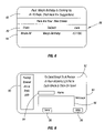
- FIG. 8 is a graphical user interface in accordance with another embodiment of the present invention.
- FIG. 9 is a graphical user interface in accordance with another embodiment of the present invention.
- FIG. 10 is a flow chart for software for setting up a client processor-based system in accordance with one embodiment of the present invention.
- FIG. 11 is a flow chart for software for setting up a server in accordance with one embodiment of the present invention.
- FIG. 12 is a flow chart for software resident on the client for implementing one embodiment of the present invention.
- FIG. 13 is a perspective view of an appliance in accordance with one embodiment of the present invention.
- FIG. 14 is block depiction of the embodiment of the present invention shown in FIG. 12 .
- a processor-based system at a customer's home or other location may be advantageously operated to facilitate the interests of the customer and the retail vendor.
- the customer may be asked to provide information to the service provider, who is independent from the retail vendor, to customize the options afforded to the customer on the customer's processor-based system.
- the service provider provides Internet services to the customer on behalf of the retail vendor. In return for those services, the customer is requested to first receive content related to the products or services of the retail vendor before accessing the Internet services from the service provider.
- the service provider may provide a series of graphical user interfaces which include content related to the retail vendor such as advertisements and in addition obtains information from the customer to further customize the options made available to the customer.
- content related to the retail vendor such as advertisements
- the service provider may provide a series of graphical user interfaces which include content related to the retail vendor such as advertisements and in addition obtains information from the customer to further customize the options made available to the customer.
- the retail vendor is afforded a preferred link to an individual customer.
- the customer receives simple-to-use Internet services and access to customized information related to the retail vendor.
- the service provider may be able to provide the customer with a processor-based system at a reduced cost.
- a system 10 for remotely managing and controlling a plurality of consumer appliances includes a service provider 16 and one or more web servers 18 coupled over the Internet 14 .
- a consumer may use the home-based client system 12 .
- the service provider 16 in the form of a server processor-based system may control the system 10 in accordance with one embodiment of the present invention.
- Each web server 18 may be associated with a different retail vendor.
- a retail vendor is an entity that provides products or services to consumers. Each retail vendor may arrange for a service provider 16 to provide remote management and control of a number of client systems 12 in accordance with one embodiment of the present invention.
- the service provider 16 may provide a large number of consumers 13 with personalized service 11 through a client system 12 .
- This personalized service 11 may be provided by obtaining information from the consumer 13 about the consumer's preferences. Based on that information, the service provider 16 can provide information to the consumer 13 that is modified, or tailored to reflect that consumer's preferences.
- the consumer 13 may allow the service provider 16 to control the consumer's client system 12 .
- This control may include providing user interfaces that provide targeted information about a particular retail vendor.
- the control may limit the options that the consumer must consider. Therefore, a relatively close association may be achieved between a retail vendor 19 and a consumer 13 as a result of the services provided by the service provider 16 .
- the service provider 16 may develop a close relationship between the retail vendor 19 and a plurality of consumers 13 by providing personalized, dedicated service to each consumer 13 through his or her client system 12 .
- the consumer 13 may provide information to a secure service provider 16 that utilizes the information to provide dedicated information and services to the consumer.
- the information and services may be customized in accordance with the customer's preferences received by the service provider 16 in confidence. In one embodiment of the present invention, this information may not be provided to the retail vendor 19 . Instead, the retail vendor 19 uses the service provider 16 as a proxy to provide the dedicated services.
- the consumer 13 who may have a high degree of confidence in the service provider 16 , may feel secure that the information provided to the service provider 16 will not be misused.
- the service provider 16 may provide similar, but separately customized services, for any number of retail vendors 19 .
- Each of those vendors 19 may operate a web site using a web server 18 and each of those vendors may provide different services and products to consumers 13 .
- the service provider 16 controls the information displayed on the client system 12 and provides Internet and e-mail services as well.
- the service provider 16 acts as the Internet service provider for the client system 12 .
- the service provider 16 may provide targeted information to the client system 12 on behalf of a particular retail vendor 19 .
- the retail vendor 19 may support the acquisition of the client system 12 by the consumer 13 .
- the consumer 13 may be afforded an advantageous price for the client system 12 as a result of the association with the retail vendor 19 .
- this arrangement may enable consumers, who would otherwise be unwilling to incur the costs associated with obtaining and maintaining a client system 12 , to acquire such systems.
- the consumer 13 may implement sales transactions “S” either directly with the retail vendor 19 or through the service provider 16 .
- sales transactions “S” either directly with the retail vendor 19 or through the service provider 16 .
- the consumer 13 receives that information and level of service that the consumer expects and in return the consumer consummates sales transactions with the retail vendor 19 .
- an exemplary graphical user interface 20 supported by the client system 12 may be sponsored by a retail vendor 19 , such as Brick & Mortar Retailers, Inc. as indicated at 22 .
- the interface 20 may be provided by the service provider 16 on behalf of the retail vendor 19 .
- the interface 20 may appear upon power up and booting of the client system 12 .
- the interface 20 may pose a request to a particular user who responds by entering his or her name, for example by mouse clicking on an appropriate icon 26 .
- the service provider 16 may already be aware of the family members of a particular family. However, it may be useful, in each case, to know which particular family member is logging onto the system 10 . This facilitates the targeting of information not only for a particular family but also to particular members of the family. In the illustrated example, the father, Paul, has clicked on the icon 26 a using the mouse cursor 28 .
- the interface 30 is displayed, as shown in FIG. 3 , in response to Paul's input.
- the interface 30 is customized to the preferences of the user named Paul as indicated at 32 .
- the user is then asked to choose a selection as indicated at 34 .
- Potential user selections may be displayed as an icon 36 a for making a purchase, an icon 36 b for requesting information, icon 36 c for viewing a catalog, an icon 36 d for using a store locator or an icon 36 e for selecting an unlisted choice. Selection of any of the icons 36 a , 36 b , 36 c or 36 d may automatically send the consumer to the retail vendor's web site served by a web server 18 .
- the interface 30 may also provide a help button 38 .
- targeted advertising such as banner advertising 39 may be provided on the interface 30 . Knowing that Paul has logged on and knowing the particular family, the system 10 may provide advertising that is targeted to the active user. Since the system 10 knows that Paul has purchased tools in the past, Paul may be advised by a banner advertisement 39 of a special on tools. The system 10 may know the family circumstances, spending habits, available credit and other information. The available information may be compiled to select advertising that most fits the needs and interests of the active user.
- the system 10 is dedicated to the purposes of a retail vendor 19 .
- the icons 36 primarily offer information pertinent to that retail vendor 19 . If the user wishes to obtain information not related to the retail vendor 19 , the user must select the other icon 36 e to obtain the interface 40 shown in FIG. 4 .
- the user can select an icon 44 a to access a particular Internet site, an icon 44 b to conduct an Internet search, an icon 44 c to receive e-mail and an icon 44 d to send e-mail.
- Each of the icons 44 is intended to provide a specific and clear function, making the use of the client system 12 appliance-like in its simplicity.
- the service provider 16 can provide better control over the user's experience and may provide simplicity at the same time.
- advertising 46 may be provided through the interface 40 . Knowing the circumstances of the particular user, the advertising may be either customized to a user or selected to be of the greatest interest to the user.
- the client system 12 is effectively controlled by the service provider 16 and software on the client system 12 .
- the user is not free to immediately select any Internet site but instead must peruse a series of interfaces 20 and 30 , controlled by the system 10 , to reach the “other” interface 40 .
- the system 10 controls what information may be viewed and how the user interacts with the client system 12 .
- selection of the help button 38 ( FIG. 3 ) generates the interface 50 in accordance with one embodiment of the present invention.
- the user may be asked, through the interface 50 , to indicate a selection.
- the user may report a client system 12 problem by selecting the icon 54 a .
- a report may be provided to the service provider 16 about the problem.
- a dedicated port may be provided to the client system 12 so that the service provider 16 may diagnose the problem.
- the service provider 16 may remotely manage the client system 12 to overcome the problem.
- the service provider 16 is responsible for maintaining the client system 12 in working order.
- the service provider 16 may control the user's ability to add additional hardware or software to the client system 12 . This ensures that the client system 12 runs as intended and reduces the possibility of unexpected software or hardware problems.
- the user may receive guidance on how to use the various graphical user interfaces.
- the user may be offered an opportunity to alter some system settings as indicated in icon 54 c .
- the user may alter backgrounds, type fonts and the like.
- the user can not alter the content of the interfaces that are controlled by the service provider 16 . That is, in order to access information (and in fact to use the system 10 ), in one embodiment of the present invention, the user must progress through a series of graphical user interfaces dictated by the service provider 16 and its interaction with the client system 12 .
- the interface 50 may also include a targeted advertisement 56 .
- the graphical user interface 60 is provided to facilitate accessing a known Internet site.
- directions are provided, as indicated in 62 , to facilitate the entry of the web site's address.
- the user may only be asked to enter a portion of the uniform resource locator in the window 64 to facilitate that entry.
- a help button 38 may be provided as well.
- targeted advertising in the form of a banner ad 66 may be included. In this way, the user gets relatively simple on screen directions to implement one specific function.
- the graphical user interface 70 appears, as shown in FIG. 7 .
- the user gets relatively straightforward directed instructions to perform a specific function, in this case an Internet search.
- the user may be asked to enter three words (utilized as search terms) in the windows 72 a , 72 b and 72 c .
- the client system 12 may implement the search using the first entered word. If too many sites are found in the search, the word contained in the second box may be utilized to narrow the search. Similarly, the word in the third box may be added to further narrow the search, if needed.
- an advertisement targeted to the particular user may be provided, for example as the banner ad 74 .
- the graphical user interface 80 may be created as shown in FIG. 8 .
- the e-mails that the user has received are presented in a straightforward fashion.
- An indication of the sender, the subject and the date of the e-mail may be provided as indicated at 84 .
- a simple banner 82 may provide titling for the different types of e-mail information.
- a targeted advertisement 86 may be included as well.
- the advertisement is targeted because the system knows Mary's birthday. If Paul clicks on the advertisement 86 , the system may attempt to suggest birthday presents based on Mary's past purchasing habits, items that Mary has looked at on-line or other information.
- the graphical user interface 90 appears as shown in FIG. 9 .
- simple instructions 92 are provided to facilitate the generation of an e-mail message.
- the user may be asked to simply insert the name of the targeted recipient at window 94 and may be provided with a specific area 96 to type in a message. The user then merely clicks on a send button 98 to transmit the message. Also, targeted advertising 99 may be provided.
- the software 1060 for setting up the client system 12 begins by requesting the names of the intended users of the client system 12 (block 1062 ).
- the client system 12 generates a set up graphical user interface for each named user as indicated in block 1064 . Thereafter, the client system 12 iterates through each user to request user preferences as indicated in block 1066 .
- the first user to use the client system 12 may be asked to provide the preferences for the other users.
- that user may be asked to enter his or her own preferences in order to gain access to the services provided by the service provider 16 .
- the client system 12 forwards the preferences to the service provider 16 as indicated in block 1067 . This may be done by creating a link to the service provider 16 over the Internet 14 . Alternatively, the information may be forwarded over a back channel such as a telephone link. For example, the telephone link may be through a one eight hundred number so that the call does not in any way effect the consumer's telephone bill.
- the client system 12 may receive graphical user interfaces for each user based on his or her preference indications, as indicated in block 1068 .
- the graphical user interfaces may be resident on the client system 12 .
- the client system 12 also receives a user code for correlating user activities to each particular user as indicated in block 1069 .
- User activities include the gamut of activities that the user may undertake on the system 12 .
- a log of each item that was selected by the particular user may be compiled.
- This information, correlated to the user's code and to a client system 12 code, may be provided at appropriate intervals to the service provider 16 . This information may be further utilized for a variety of purposes including improving the targeting of advertising materials for each particular user.
- the software 1170 On the service provider 16 side, the software 1170 , shown in FIG. 11 , is responsible for initiating a particular user.
- the service provider 16 may receive the user's name, the client system 12 identifier and the user's preferences as indicated in block 1172 .
- This information may be stored on a storage 15 ( FIG. 1 ) in accordance with one embodiment of the present invention.
- a database may also be consulted to select the appropriate user modifications based on the preferences provided by the particular user of the client system 12 , as indicated in block 1174 .
- a preset series of survey style questions are posed. Based on the user's responses, the most appropriate set of modifications may be selected.
- a table may be stored in the storage 15 that correlates survey question responses to particular characteristics. These characteristics then may be tied to particular advertising or service based content which may be pushed to the client system 12 in one embodiment of the present invention.
- modifications may be assigned to a particular user.
- the appropriate graphical user interfaces and a user code may then be forwarded from the service provider 16 to the client system 12 as indicated in block 1176 .
- Those modifications, graphical user interfaces and client identifiers may be stored on an appropriate storage on the client system 12 .
- the software 1280 is resident on the client system 12 , in accordance with one embodiment of the present invention shown in FIG. 12 .
- the software 1280 may begin, as indicated in block 1281 by displaying the setup graphical user interface 20 .
- the client system 12 receives a user selection of one of the icons 26 to identify the active user, as indicated in diamond 1282 .
- the user's preferences may be accessed as indicated in block 1283 .
- the ensuing graphical user interfaces may be modified in accordance with those preferences as indicated in block 1284 . These modifications may be developed by the client system 12 or, alternatively, may be downloaded from the service provider 16 .
- a user selection may be received through the graphical user interface 30 , shown in FIG. 3 , as indicated by diamond 1285 in FIG. 12 .
- the particular selection may be utilized to access the user preferences (block 1286 ).
- an activity graphical user interface (such as the interfaces shown in FIGS. 2 through 9 ) for the user may be modified as indicated in block 1287 .
- Each of these activities may be implemented either using software resident on the client system 12 or based on downloads from the service provider 16 .
- each activity undertaken by a particular user on the system may be recorded and forwarded to the service provider 16 for analysis. As a result of that analysis, the customization for a particular user may be further refined.
- An example of the client system 12 may have a unitary housing including a base 1306 and a monitor 1302 .
- a keyboard 1310 may stored in a slot 1312 in the base 1306 .
- the system 12 has an appliance-like, compact appearance.
- a display 1308 may be utilized to display the various graphical user interfaces.
- a telephone 1304 may be provided which may be operable through the client system 12 .
- the client system 12 may include a processor 1400 coupled to a bridge 1402 , as shown in FIG. 14 .
- the bridge 1402 provides an interface between a graphics controller 1406 , a bus 1408 and the system memory 1404 .
- the graphics controller 1406 may be coupled to the display 1308 .
- a bus 1410 may be coupled to the bridge 1402 .
- the bus 1410 may include slots that may connect to peripheral devices (not shown).
- the bus 1410 also is coupled to another bridge 1412 .
- the bridge 1412 is coupled to a hard disk drive 1414 and another bus 1416 .
- the hard disk drive 1414 may store the software 1060 and 1280 in accordance with one embodiment of the present invention.
- the bus 1416 may be coupled to a serial input/output (SIO) device 1418 and a basic input/output system (BIOS) memory 1424 .
- the SIO device 1418 may couple the keyboard 1310 and a modem 1420 that provides access to a phone line.
- the modem 1420 may be utilized in one embodiment of the present invention to gain access to the Internet 14 .
Abstract
Description
Claims (15)
Priority Applications (9)
| Application Number | Priority Date | Filing Date | Title |
|---|---|---|---|
| US09/584,520 US7729943B1 (en) | 2000-05-31 | 2000-05-31 | Remotely managing and controlling a consumer appliance |
| PCT/US2001/016135 WO2001093155A2 (en) | 2000-05-31 | 2001-05-17 | Remotely managing and controlling a consumer appliance |
| CN01810450A CN1432167A (en) | 2000-05-31 | 2001-05-17 | Remotely managing and controlling consumer appliance |
| KR1020027016275A KR100563554B1 (en) | 2000-05-31 | 2001-05-17 | Remotely managing and controlling a consumer appliance |
| AU2001261765A AU2001261765A1 (en) | 2000-05-31 | 2001-05-17 | Remotely managing and controlling a consumer appliance |
| CA002408276A CA2408276A1 (en) | 2000-05-31 | 2001-05-17 | Remotely managing and controlling a consumer appliance |
| JP2002500291A JP2003535402A (en) | 2000-05-31 | 2001-05-17 | Method and system for remotely managing and controlling consumer equipment |
| EP01935694A EP1285384A1 (en) | 2000-05-31 | 2001-05-17 | Remotely managing and controlling a consumer appliance |
| TW090113072A TWI242733B (en) | 2000-05-31 | 2001-05-30 | Remotely managing and controlling a consumer appliance |
Applications Claiming Priority (1)
| Application Number | Priority Date | Filing Date | Title |
|---|---|---|---|
| US09/584,520 US7729943B1 (en) | 2000-05-31 | 2000-05-31 | Remotely managing and controlling a consumer appliance |
Publications (1)
| Publication Number | Publication Date |
|---|---|
| US7729943B1 true US7729943B1 (en) | 2010-06-01 |
Family
ID=24337651
Family Applications (1)
| Application Number | Title | Priority Date | Filing Date |
|---|---|---|---|
| US09/584,520 Expired - Lifetime US7729943B1 (en) | 2000-05-31 | 2000-05-31 | Remotely managing and controlling a consumer appliance |
Country Status (9)
| Country | Link |
|---|---|
| US (1) | US7729943B1 (en) |
| EP (1) | EP1285384A1 (en) |
| JP (1) | JP2003535402A (en) |
| KR (1) | KR100563554B1 (en) |
| CN (1) | CN1432167A (en) |
| AU (1) | AU2001261765A1 (en) |
| CA (1) | CA2408276A1 (en) |
| TW (1) | TWI242733B (en) |
| WO (1) | WO2001093155A2 (en) |
Cited By (3)
| Publication number | Priority date | Publication date | Assignee | Title |
|---|---|---|---|---|
| US20060048198A1 (en) * | 2004-08-24 | 2006-03-02 | Hewlett-Packard Development Company, L.P. | Establishing remote connections |
| US20110126120A1 (en) * | 2001-02-28 | 2011-05-26 | Brittingham Brian S | Computerized Interface For Monitoring Financial Information And Executing Financial Transactions |
| US20140192800A1 (en) * | 2000-06-29 | 2014-07-10 | Ching-Yi Lin | Phone appliance with display screen and methods of using the same |
Families Citing this family (7)
| Publication number | Priority date | Publication date | Assignee | Title |
|---|---|---|---|---|
| US7257638B2 (en) * | 2001-12-20 | 2007-08-14 | Microsoft Corporation | Distributing network applications |
| US9269068B2 (en) | 2006-05-05 | 2016-02-23 | Visible Technologies Llc | Systems and methods for consumer-generated media reputation management |
| US9094638B2 (en) * | 2006-05-05 | 2015-07-28 | Alcatel Lucent | Portable contextual menu for triple play service |
| US20090106697A1 (en) | 2006-05-05 | 2009-04-23 | Miles Ward | Systems and methods for consumer-generated media reputation management |
| US8280550B2 (en) * | 2008-06-17 | 2012-10-02 | Omnicell, Inc. | Cabinet with remote integration |
| WO2010065199A1 (en) * | 2008-08-15 | 2010-06-10 | Visible Technologies Llc | Systems and methods for consumer-generated media reputation management |
| JP2022072383A (en) * | 2020-10-29 | 2022-05-17 | 株式会社Ipsign | System, method, and program for extracting infringement information |
Citations (14)
| Publication number | Priority date | Publication date | Assignee | Title |
|---|---|---|---|---|
| US5774652A (en) * | 1995-09-29 | 1998-06-30 | Smith; Perry | Restricted access computer system |
| US5778187A (en) * | 1996-05-09 | 1998-07-07 | Netcast Communications Corp. | Multicasting method and apparatus |
| US5802518A (en) * | 1996-06-04 | 1998-09-01 | Multex Systems, Inc. | Information delivery system and method |
| US5855008A (en) * | 1995-12-11 | 1998-12-29 | Cybergold, Inc. | Attention brokerage |
| US5907617A (en) * | 1995-06-07 | 1999-05-25 | Digital River, Inc. | Try before you buy software distribution and marketing system |
| KR19990078766A (en) | 1999-08-05 | 1999-11-05 | 신종관 | Method for Electronic Commerce Capable of Multi-Shoping by One Membership |
| KR19990087923A (en) | 1998-05-05 | 1999-12-27 | 포만 제프리 엘 | Client-server systems with central application management allowing an administrator to configure end user applications by executing them in the context of users and groups |
| US6009469A (en) * | 1995-09-25 | 1999-12-28 | Netspeak Corporation | Graphic user interface for internet telephony application |
| JP2000013524A (en) | 1998-06-23 | 2000-01-14 | Kazuhiro Shiina | Internet connection device, viewer terminal equipment incorporating the same, and information service system utilizing broadcasting |
| KR20000024523A (en) | 2000-02-18 | 2000-05-06 | 변승환 | An internet tailored information service system |
| US6237022B1 (en) * | 1999-03-15 | 2001-05-22 | Webtv Networks, Inc. | System and method for distributing preferenced data over a communications network |
| US6298348B1 (en) * | 1998-12-03 | 2001-10-02 | Expanse Networks, Inc. | Consumer profiling system |
| US6308175B1 (en) * | 1996-04-04 | 2001-10-23 | Lycos, Inc. | Integrated collaborative/content-based filter structure employing selectively shared, content-based profile data to evaluate information entities in a massive information network |
| US6412073B1 (en) * | 1998-12-08 | 2002-06-25 | Yodiee.Com, Inc | Method and apparatus for providing and maintaining a user-interactive portal system accessible via internet or other switched-packet-network |
-
2000
- 2000-05-31 US US09/584,520 patent/US7729943B1/en not_active Expired - Lifetime
-
2001
- 2001-05-17 CN CN01810450A patent/CN1432167A/en active Pending
- 2001-05-17 JP JP2002500291A patent/JP2003535402A/en active Pending
- 2001-05-17 KR KR1020027016275A patent/KR100563554B1/en not_active IP Right Cessation
- 2001-05-17 AU AU2001261765A patent/AU2001261765A1/en not_active Abandoned
- 2001-05-17 WO PCT/US2001/016135 patent/WO2001093155A2/en active IP Right Grant
- 2001-05-17 EP EP01935694A patent/EP1285384A1/en not_active Withdrawn
- 2001-05-17 CA CA002408276A patent/CA2408276A1/en not_active Abandoned
- 2001-05-30 TW TW090113072A patent/TWI242733B/en not_active IP Right Cessation
Patent Citations (15)
| Publication number | Priority date | Publication date | Assignee | Title |
|---|---|---|---|---|
| US5907617A (en) * | 1995-06-07 | 1999-05-25 | Digital River, Inc. | Try before you buy software distribution and marketing system |
| US6009469A (en) * | 1995-09-25 | 1999-12-28 | Netspeak Corporation | Graphic user interface for internet telephony application |
| US5774652A (en) * | 1995-09-29 | 1998-06-30 | Smith; Perry | Restricted access computer system |
| US5855008A (en) * | 1995-12-11 | 1998-12-29 | Cybergold, Inc. | Attention brokerage |
| US6308175B1 (en) * | 1996-04-04 | 2001-10-23 | Lycos, Inc. | Integrated collaborative/content-based filter structure employing selectively shared, content-based profile data to evaluate information entities in a massive information network |
| US5778187A (en) * | 1996-05-09 | 1998-07-07 | Netcast Communications Corp. | Multicasting method and apparatus |
| US5802518A (en) * | 1996-06-04 | 1998-09-01 | Multex Systems, Inc. | Information delivery system and method |
| KR19990087923A (en) | 1998-05-05 | 1999-12-27 | 포만 제프리 엘 | Client-server systems with central application management allowing an administrator to configure end user applications by executing them in the context of users and groups |
| US6205476B1 (en) | 1998-05-05 | 2001-03-20 | International Business Machines Corporation | Client—server system with central application management allowing an administrator to configure end user applications by executing them in the context of users and groups |
| JP2000013524A (en) | 1998-06-23 | 2000-01-14 | Kazuhiro Shiina | Internet connection device, viewer terminal equipment incorporating the same, and information service system utilizing broadcasting |
| US6298348B1 (en) * | 1998-12-03 | 2001-10-02 | Expanse Networks, Inc. | Consumer profiling system |
| US6412073B1 (en) * | 1998-12-08 | 2002-06-25 | Yodiee.Com, Inc | Method and apparatus for providing and maintaining a user-interactive portal system accessible via internet or other switched-packet-network |
| US6237022B1 (en) * | 1999-03-15 | 2001-05-22 | Webtv Networks, Inc. | System and method for distributing preferenced data over a communications network |
| KR19990078766A (en) | 1999-08-05 | 1999-11-05 | 신종관 | Method for Electronic Commerce Capable of Multi-Shoping by One Membership |
| KR20000024523A (en) | 2000-02-18 | 2000-05-06 | 변승환 | An internet tailored information service system |
Non-Patent Citations (23)
| Title |
|---|
| A service in kind; Tele.Com; Manhasset; May 3, 1999; Anne Zieger. * |
| Beyond bots; Collaborative filtering firms enter more E-Commerce venues despite privacy concerns.; Report on Electronic Commerce; Washington; Sep. 8, 1998; Gary H Arlen. * |
| BISYS® Enables Financial Institutions to Bring Direct Internet Access Services to Their Customers; Jan. 10, 2000. * |
| Brand3 touts branded Net access, Adweek; New York; Mar. 6, 2000; Janis Mara. * |
| Branded Internet Access: Traditional Business Gets a New Lock on Customers Through iDigi Networks; PR Newswire; New York; Aug. 20 1999. * |
| Ikano expands DSL availability through a strategic partnership with New Edge Networks; PR Newswire; Mar. 13, 2000. * |
| Informatica and Net Perceptions form strategic partnership to provide E-Commerce companies with powerful e-CRM Solution; PR Newswire; New York; Mar. 16, 2000. * |
| Intel launches ISP programs; Computerworld; staff writer; Nov. 8, 1999; http://www.computerworld.com.au/index.php/id. * |
| Intel wants to be the ISP's ISP; ZDNet.co.uk; Apr. 23, 1999; http://www.zdnet.co.uk/misc/print. * |
| Internet America, Inc. Announces Pact With Netsurfer; Netsurfer Software Will Make Signing up Fast and Easy; PR Newswire; New York; Jun. 8, 1999. * |
| Internet Entrepreneur eyes a new web service his company, I2EYENET.COM launches its "background" operation today; The Post-Standard; Syracuse; Aug. 6, 1999; Tim Knauss Staff writer. * |
| Internet Entrepreneur eyes a new web service his company, I2EYENET.COM launches its "background" operation today; The Post—Standard; Syracuse; Aug. 6, 1999; Tim Knauss Staff writer. * |
| Local Internet Co. Working to Change Face of On-line Banking; The Business Journal-Central New York; Syracuse; Dec. 17, 1999; Mark Hadley. * |
| Local Internet Co. Working to Change Face of On-line Banking; The Business Journal—Central New York; Syracuse; Dec. 17, 1999; Mark Hadley. * |
| Meet the "virtual ISP", Telephony, Aug. 10, 1998, Vince Vittore. * |
| Netsurfer makes it easy; Get subscribers, get tem online; and start making more money; Dodd Judd Erickson; Jan. 2000, www.boardwarch.com. * |
| Netsurfer, Inc. Becomes Approved Vendor to the Internet Service Provider's Consortium; Janice Lewis. Jun. 8, 1998. * |
| Ubrandit.com to expand its Internet offerings to include a fully branded virtual ISP Portal Service to companies and affinity Groups; Business Wire; New York; Mar. 7, 2000; Business Editors. * |
| Virtual ISP, ZipLink website, at http://www.ziplink.com/visp (last visited Apr. 24, 2007). |
| Virtual ISP-How It Works, ZipLink website, at http://www.ziplink.com/visp/howitworks.shtml (last visited Apr. 24, 2007). |
| Virtual ISP—How It Works, ZipLink website, at http://www.ziplink.com/visp/howitworks.shtml (last visited Apr. 24, 2007). |
| ZipLink, virtual ISP now everyone connects, www.ziplink.com/visp, Mar. 3, 2000, 7 pgs. |
| Ziplink's Virtual Internet Service Provider (ISP) Program Provides Complete Turnkeys Outsourcing Option; PR Newswire; New York; Nov. 4, 1999. * |
Cited By (5)
| Publication number | Priority date | Publication date | Assignee | Title |
|---|---|---|---|---|
| US20140192800A1 (en) * | 2000-06-29 | 2014-07-10 | Ching-Yi Lin | Phone appliance with display screen and methods of using the same |
| US11563834B2 (en) | 2000-06-29 | 2023-01-24 | Ching-Yi Lin | Phone appliance with display screen and methods for using the same |
| US11652914B2 (en) * | 2000-06-29 | 2023-05-16 | Ching-Yi Lin | Phone appliance with display screen and methods of using the same |
| US20110126120A1 (en) * | 2001-02-28 | 2011-05-26 | Brittingham Brian S | Computerized Interface For Monitoring Financial Information And Executing Financial Transactions |
| US20060048198A1 (en) * | 2004-08-24 | 2006-03-02 | Hewlett-Packard Development Company, L.P. | Establishing remote connections |
Also Published As
| Publication number | Publication date |
|---|---|
| AU2001261765A1 (en) | 2001-12-11 |
| WO2001093155A2 (en) | 2001-12-06 |
| JP2003535402A (en) | 2003-11-25 |
| KR100563554B1 (en) | 2006-03-27 |
| TWI242733B (en) | 2005-11-01 |
| CA2408276A1 (en) | 2001-12-06 |
| KR20030007779A (en) | 2003-01-23 |
| CN1432167A (en) | 2003-07-23 |
| EP1285384A1 (en) | 2003-02-26 |
Similar Documents
| Publication | Publication Date | Title |
|---|---|---|
| US8738439B2 (en) | Targeting of advertisements to users of an online service | |
| US6148332A (en) | Mandatory message display and reporting system | |
| US6928615B1 (en) | Independent internet client object with ad display capabilities | |
| US9519929B2 (en) | Method and apparatus for providing a shopping list service | |
| US7730424B2 (en) | Methods and systems for displaying information on a graphical user interface | |
| US6014638A (en) | System for customizing computer displays in accordance with user preferences | |
| US6766369B1 (en) | Internet service error tracking | |
| US6983311B1 (en) | Access to internet search capabilities | |
| EP1083504A2 (en) | Dynamic ad targeting by an internet server | |
| US20050097190A1 (en) | System and method for customized portal web pages | |
| US20040098449A1 (en) | System and method for disseminating information over a communication network according to predefined consumer profiles | |
| US20070143178A1 (en) | Methods and systems for facilitating communications between parties | |
| US7020690B1 (en) | Inactivity timer for an internet client | |
| US20030052928A1 (en) | System for and method of interactive screen savers | |
| US20020107776A1 (en) | System and method for anonymous lead generation and management | |
| WO2000054201A2 (en) | Dynamic ad targeting by an internet server | |
| US7729943B1 (en) | Remotely managing and controlling a consumer appliance | |
| US20010051978A1 (en) | Method and apparatus for providing a personalization service across a network | |
| KR20060076779A (en) | Command center and interface for web based business merchandising and service | |
| US20020170040A1 (en) | Computer implemented user relationship maintenance technique for target software application | |
| US8438058B2 (en) | Internet service systems and methods | |
| WO2001069480A1 (en) | A computer advertisement method using an advertisement dedicated program | |
| KR20020037976A (en) | Method for Providing Advertisement and Information in the Internet Using Menu which Appears on User's Mouse Click | |
| WO2007075768A2 (en) | Methods and systems for facilitating the communication and displaying of information between parties | |
| EP1616292A1 (en) | Electronic account statement with embedded tags |
Legal Events
| Date | Code | Title | Description |
|---|---|---|---|
| AS | Assignment |
Owner name: INTEL CORPORATION,CALIFORNIA Free format text: ASSIGNMENT OF ASSIGNORS INTEREST;ASSIGNORS:LEGLISE CLAUDE M.;MILLER, THOMAS C.;SIGNING DATES FROM 20000515 TO 20000524;REEL/FRAME:010860/0750 |
|
| STCF | Information on status: patent grant |
Free format text: PATENTED CASE |
|
| AS | Assignment |
Owner name: MICRON TECHNOLOGY, INC., IDAHO Free format text: ASSIGNMENT OF ASSIGNORS INTEREST;ASSIGNOR:NUMONYX B.V.;REEL/FRAME:027075/0682 Effective date: 20110930 |
|
| AS | Assignment |
Owner name: NUMONYX B.V., SWITZERLAND Free format text: ASSIGNMENT OF ASSIGNORS INTEREST;ASSIGNOR:INTEL CORPORATION;REEL/FRAME:028055/0625 Effective date: 20080325 |
|
| FEPP | Fee payment procedure |
Free format text: PAYOR NUMBER ASSIGNED (ORIGINAL EVENT CODE: ASPN); ENTITY STATUS OF PATENT OWNER: LARGE ENTITY |
|
| FPAY | Fee payment |
Year of fee payment: 4 |
|
| AS | Assignment |
Owner name: U.S. BANK NATIONAL ASSOCIATION, AS COLLATERAL AGENT, CALIFORNIA Free format text: SECURITY INTEREST;ASSIGNOR:MICRON TECHNOLOGY, INC.;REEL/FRAME:038669/0001 Effective date: 20160426 Owner name: U.S. BANK NATIONAL ASSOCIATION, AS COLLATERAL AGEN Free format text: SECURITY INTEREST;ASSIGNOR:MICRON TECHNOLOGY, INC.;REEL/FRAME:038669/0001 Effective date: 20160426 |
|
| AS | Assignment |
Owner name: MORGAN STANLEY SENIOR FUNDING, INC., AS COLLATERAL AGENT, MARYLAND Free format text: PATENT SECURITY AGREEMENT;ASSIGNOR:MICRON TECHNOLOGY, INC.;REEL/FRAME:038954/0001 Effective date: 20160426 Owner name: MORGAN STANLEY SENIOR FUNDING, INC., AS COLLATERAL Free format text: PATENT SECURITY AGREEMENT;ASSIGNOR:MICRON TECHNOLOGY, INC.;REEL/FRAME:038954/0001 Effective date: 20160426 |
|
| AS | Assignment |
Owner name: U.S. BANK NATIONAL ASSOCIATION, AS COLLATERAL AGENT, CALIFORNIA Free format text: CORRECTIVE ASSIGNMENT TO CORRECT THE REPLACE ERRONEOUSLY FILED PATENT #7358718 WITH THE CORRECT PATENT #7358178 PREVIOUSLY RECORDED ON REEL 038669 FRAME 0001. ASSIGNOR(S) HEREBY CONFIRMS THE SECURITY INTEREST;ASSIGNOR:MICRON TECHNOLOGY, INC.;REEL/FRAME:043079/0001 Effective date: 20160426 Owner name: U.S. BANK NATIONAL ASSOCIATION, AS COLLATERAL AGEN Free format text: CORRECTIVE ASSIGNMENT TO CORRECT THE REPLACE ERRONEOUSLY FILED PATENT #7358718 WITH THE CORRECT PATENT #7358178 PREVIOUSLY RECORDED ON REEL 038669 FRAME 0001. ASSIGNOR(S) HEREBY CONFIRMS THE SECURITY INTEREST;ASSIGNOR:MICRON TECHNOLOGY, INC.;REEL/FRAME:043079/0001 Effective date: 20160426 |
|
| FEPP | Fee payment procedure |
Free format text: MAINTENANCE FEE REMINDER MAILED (ORIGINAL EVENT CODE: REM.) |
|
| FEPP | Fee payment procedure |
Free format text: 7.5 YR SURCHARGE - LATE PMT W/IN 6 MO, LARGE ENTITY (ORIGINAL EVENT CODE: M1555) |
|
| MAFP | Maintenance fee payment |
Free format text: PAYMENT OF MAINTENANCE FEE, 8TH YEAR, LARGE ENTITY (ORIGINAL EVENT CODE: M1552) Year of fee payment: 8 |
|
| AS | Assignment |
Owner name: JPMORGAN CHASE BANK, N.A., AS COLLATERAL AGENT, ILLINOIS Free format text: SECURITY INTEREST;ASSIGNORS:MICRON TECHNOLOGY, INC.;MICRON SEMICONDUCTOR PRODUCTS, INC.;REEL/FRAME:047540/0001 Effective date: 20180703 Owner name: JPMORGAN CHASE BANK, N.A., AS COLLATERAL AGENT, IL Free format text: SECURITY INTEREST;ASSIGNORS:MICRON TECHNOLOGY, INC.;MICRON SEMICONDUCTOR PRODUCTS, INC.;REEL/FRAME:047540/0001 Effective date: 20180703 |
|
| AS | Assignment |
Owner name: MICRON TECHNOLOGY, INC., IDAHO Free format text: RELEASE BY SECURED PARTY;ASSIGNOR:U.S. BANK NATIONAL ASSOCIATION, AS COLLATERAL AGENT;REEL/FRAME:047243/0001 Effective date: 20180629 |
|
| AS | Assignment |
Owner name: MICRON TECHNOLOGY, INC., IDAHO Free format text: RELEASE BY SECURED PARTY;ASSIGNOR:MORGAN STANLEY SENIOR FUNDING, INC., AS COLLATERAL AGENT;REEL/FRAME:050937/0001 Effective date: 20190731 |
|
| AS | Assignment |
Owner name: MICRON SEMICONDUCTOR PRODUCTS, INC., IDAHO Free format text: RELEASE BY SECURED PARTY;ASSIGNOR:JPMORGAN CHASE BANK, N.A., AS COLLATERAL AGENT;REEL/FRAME:051028/0001 Effective date: 20190731 Owner name: MICRON TECHNOLOGY, INC., IDAHO Free format text: RELEASE BY SECURED PARTY;ASSIGNOR:JPMORGAN CHASE BANK, N.A., AS COLLATERAL AGENT;REEL/FRAME:051028/0001 Effective date: 20190731 |
|
| MAFP | Maintenance fee payment |
Free format text: PAYMENT OF MAINTENANCE FEE, 12TH YEAR, LARGE ENTITY (ORIGINAL EVENT CODE: M1553); ENTITY STATUS OF PATENT OWNER: LARGE ENTITY Year of fee payment: 12 |