US7725524B2 - Process automation system and method having a hierarchical architecture with multiple tiers - Google Patents
Process automation system and method having a hierarchical architecture with multiple tiers Download PDFInfo
- Publication number
- US7725524B2 US7725524B2 US11/543,582 US54358206A US7725524B2 US 7725524 B2 US7725524 B2 US 7725524B2 US 54358206 A US54358206 A US 54358206A US 7725524 B2 US7725524 B2 US 7725524B2
- Authority
- US
- United States
- Prior art keywords
- objects
- job
- properties
- job step
- project
- Prior art date
- Legal status (The legal status is an assumption and is not a legal conclusion. Google has not performed a legal analysis and makes no representation as to the accuracy of the status listed.)
- Active, expires
Links
Images


Classifications
-
- G—PHYSICS
- G06—COMPUTING; CALCULATING OR COUNTING
- G06F—ELECTRIC DIGITAL DATA PROCESSING
- G06F8/00—Arrangements for software engineering
- G06F8/70—Software maintenance or management
- G06F8/71—Version control; Configuration management
Definitions
- This invention relates generally to the field of computer aided software engineering. More particularly, the invention relates to managing distributed processes in a process automation system.
- Process automation systems are used to perform a variety of computerized tasks.
- software developers use process automation systems to build, test and package software applications.
- the functions performed by these systems may include managing source code; building executable files; executing tests on the software builds; collecting and analyzing diagnostic information related to the builds; and generating detailed reports.
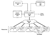
- FIG. 1 illustrates one such system developed by BuildForge, Inc. (recently acquired by International Business Machines, Inc).
- BuildForge, Inc. recently acquired by International Business Machines, Inc.
- multiple jobs 101 - 103 are executed concurrently in response to commands from a Web server 100 .
- a central database 110 enables communication between the jobs 101 - 103 and allocates resources to each of the jobs upon request. For example, when a job requires access to a particular resource, it opens a connection to the database 110 and executes a query to determine if that resource is available.
- the job waits for a period of time and then checks the database 110 again. Once the resource becomes available, it is allocated to the job and the information needed to complete the job (e.g., source files, environmental variables, etc) is retrieved from the database. The database is then updated to reflect the allocation of the resource to the new job.
- the information needed to complete the job e.g., source files, environmental variables, etc
- one embodiment of the invention implements a general purpose property mechanism in which arbitrary data is attached to any object in the system (e.g., projects, procedures, jobs, job steps, resources, etc), thereby providing a convenient way to configure the system without modifying the underlying program code.
- a three-tier hierarchy of data object is employed: “projects,” “procedures,” and “steps” (or “projects,” “jobs” and “job steps” during runtime).
- a property may be attached to any object on any tier of the hierarchy to configure that object and (potentially) all of the objects which reference the property.
- the properties and property sheets may be attached both statically (before runtime) and dynamically (during runtime).
- one embodiment of the invention employs a unique property substitution syntax to allow the value for a particular property to be located and substituted dynamically at runtime.
- the report generation process is logically separated into a data gathering stage and a report generation stage.
- the data gathering stage extracts certain specified properties and diagnostic information from each job step.
- the extracted information is then stored in a highly flexible, reusable data format which is used to create different types of user-configurable reports.
- FIG. 1 illustrates an exemplary prior art distributed process automation system.
- FIG. 2 a illustrates a system architecture according to one embodiment of the invention.
- FIG. 2 b illustrates a central command server according to one embodiment of the invention.
- FIG. 2 c illustrates one embodiment of the invention in which one or more of the agents are configured as build machines for performing program builds.
- FIG. 2 d illustrates a Web-based graphical user interface employed in one embodiment of the invention.
- FIGS. 3 a - b illustrate property attachment mechanisms employed in one embodiment of the invention.
- FIG. 4 illustrates a property sheet hierarchy employed in one embodiment of the invention.
- FIG. 5 illustrates a parameter substitution syntax employed in one embodiment of the invention.
- FIG. 6 illustrates data gathering and report generation employed in one embodiment of the invention.
- FIG. 7 illustrates a first report generated in accordance with one embodiment of the invention.
- FIG. 8 illustrates a second report generated in accordance with one embodiment of the invention.
- one embodiment of the invention implements a general purpose property mechanism in which arbitrary data is attached to any object in the system (e.g., projects, procedures, jobs, job steps, resources, etc), thereby providing a convenient way to configure the system without modifying the underlying program code.
- a three-tier hierarchy of data object is employed: “projects,” “procedures,” and “steps” (or “projects,” “jobs” and “job steps” during runtime).
- a property may be attached to any object on any tier of the hierarchy to configure that object and (potentially) all of the objects which reference the property.
- the properties and property sheets may be attached both statically (before runtime) and dynamically (during runtime).
- one embodiment of the invention employs a unique property substitution syntax to allow the value for a particular property to be located and substituted dynamically at runtime.
- the report generation process is logically separated into a data gathering stage and a report generation stage.
- the data gathering stage extracts certain specified metrics and diagnostic information from each job step.
- the extracted information is then stored in a highly flexible, reusable data format which is used to create different types of user-configurable reports.
- FIG. 2 a illustrates a system architecture according to one embodiment of the invention which includes a central command server 200 , a Web server 201 , a central database 210 , a command line tool 202 , and a plurality of system agents 230 - 234 (sometimes referred to as system “resources”) which communicate with the central command server over a network 220 .
- a central command server 200 a Web server 201 , a central database 210 , a command line tool 202 , and a plurality of system agents 230 - 234 (sometimes referred to as system “resources”) which communicate with the central command server over a network 220 .
- system agents 230 - 234 sometimes referred to as system “resources”
- the central command server 200 implements the various property management techniques described below and acts as a central arbiter for access to both the central database 210 and the system agents 230 - 234 .
- the central command server 200 includes property attachment logic 250 for executing the property attachment mechanisms described herein; parameter substitution logic 252 for substituting parameters within projects, procedures, jobs, and steps using properties; scheduling logic 251 for executing jobs on the agents 230 - 234 based on a predefined execution schedule; and resource management logic 253 for continually monitoring the state of each of the agents 230 - 234 and initiating new jobs only when resources for those jobs are available.
- post-processing logic 260 comprised of a post-processing engine 254 for gathering and processing data related to the execution of each job step; and a report generator 255 for generating associated reports. The details of each of these system components will be described in detail below.
- the Web server 201 provides a graphical Web-based interface to control the central command server.
- the Web server 201 allows users to enter execution schedules (e.g., nightly builds, tests, etc); manually initiate projects and procedures; associate properties (and property sheets) with objects; and review logs and reports.
- An exemplary Web-based user interface is illustrated in FIG. 2 d which includes a listing of each of the custom properties 391 associated with a particular procedure.
- a “create new property” link 290 is provided to allow the user to specify additional properties and attach the properties to the procedure.
- the link 290 is selected, the user is provided with a set of data entry fields (not shown) in which to enter the name/value pairs for each property.
- the command line tool 202 provides similar functionality to the Web server but using shell commands rather than graphical user interface elements. It should be noted, however, that the underlying principles of the invention are not limited to any particular type of user interface.
- the central database 210 is a relational database such as those currently available from Oracle, Microsoft, and IBM. In another embodiment, the MySql database is used.
- the central command server 200 communicates with the central database 210 using standard Relational Database Management System (RDBMS) commands and queries.
- RDBMS Relational Database Management System
- any type of database system may be employed while still complying with the underlying principles of the invention.
- the central database 210 stores information about all of the objects in the system such as projects, procedures, steps, schedules, and jobs.
- Information stored in the database falls into four general classes: a description of the various processes to be executed (procedures, steps, etc); information about when to execute the various processes (schedules); and information about the results of executing processes (results of the jobs and job steps); and administrative information such as information related to users and groups.
- the network 220 is an Ethernet network for coupling the central command server to each of the agents 230 - 234 (e.g., a 100 Mbit/s or 1000 Mbit/s network).
- the agents 230 - 234 e.g., a 100 Mbit/s or 1000 Mbit/s network.
- any network hardware or protocols may be used.
- One particular implementation runs over TCP/IP, and uses HTTP for the basic exchange mechanism, with XML used to represent the data in the messages.
- the agents 230 - 234 may be heterogeneous servers, equipped with different operating systems and/or processing capabilities.
- the agents 230 - 234 may include Solaris machines, Windows machines (e.g., Windows XP, 2003, etc), and Linux machines.
- the particular type of machine on which a job is to execute may be specified by the user via the Web server 201 and command-line tool 202 and/or may be selected automatically by the central command server 200 based on the resource requirements of the job.
- FIG. 2 a Although only five agents are illustrated in FIG. 2 a , virtually any number of agents may be coupled to the system while still complying with the underlying principles of the invention.
- One or more of the agents 230 - 234 may be configured as “build machines” for performing program builds in response to commands from the command server 200 and/or the user.
- FIG. 2 c illustrates one such implementation in which an agent 234 initiates and controls a program build by executing jobs in parallel across a series of nodes 260 - 265 .
- the cluster manager 270 illustrated in FIG. 2 c monitors the status of each of the nodes and allocates nodes to the build machine 234 upon request.
- the cluster manager 270 may be implemented as a module within the central command server 200 .
- the build machine 234 , cluster manager 270 and nodes 260 - 265 operate as described in U.S. Pat. No. 7,086,063, Ser. No. 10/397,139, entitled S YSTEM AND M ETHOD FOR F ILE C ACHING IN A D ISTRIBUTED P ROGRAM B UILD E NVIRONMENT , which is assigned to the assignee of the present application and which is incorporated herein by reference.
- One additional implementation in which source files are exchanged directly between nodes is described in the co-pending patent application entitled A S YSTEM AND M ETHOD FOR I NTELLIGENTLY D ISTRIBUTING S OURCE F ILES W ITHIN A D ISTRIBUTED B UILD E NVIRONMENT , Ser. No. 10/715,974, Filed Nov. 17, 2003, which is also assigned to the assignee of the present application and which is incorporated herein by reference.
- the property attachment logic 250 within the central command server 200 implements a general purpose property mechanism in which arbitrary data may be attached to any object in the system.
- One exemplary multi-tiered architecture illustrated in FIG. 3 a , includes a “resource” object 302 with a group of attached properties 303 a - b and a “project” object 304 with a group of attached properties 305 a - b.
- the resource object 302 represents a particular resource in the system (e.g., a particular agent 230 - 234 ) and the properties 303 a - b associated with the resource object 302 are values defining attributes of the resource.
- property 303 a may represent a particular platform (e.g., Solaris) and property 303 b may represent a version number (e.g., version 3.4).
- Various other resource-specific properties may be attached to the resource object 302 while still complying with the underlying principles of the invention (e.g., memory size, processor type/speed, last job executed on the resource, etc).
- the project object 304 which is at the top of the multi-tier hierarchy mentioned previously, represents a particular project designed by a user.
- the project may include one or more “procedures” and each procedure may include one or more “steps.”
- each project object 304 is associated with one or more “procedure” objects 306 , 308 , 310 which represent procedures to be executed on the system resources (i.e., the agents 230 - 234 ).
- each procedure object is associated with one or more “step” objects 312 , 314 , 316 , which represent one or more commands to be executed by the system resources. As indicated in FIG.
- the central command server 200 manages the property attachment process using the central database 210 .
- tables are maintained within the central database 210 which contain steps, procedures, projects, properties, and properties.
- the container objects that associate the properties for a particular object are referred to as “property sheets.”
- the tables managed by the database mimic the hierarchy illustrated in FIG. 3 a .
- Each object in the system has a property sheet associated with it by default.
- Project objects 304 for example, are stored in the database with their property sheets.
- Database joins are used to attach a particular object to a property sheet that stores its properties.
- a property is attached to a particular object by specifying the property name and the object name to the central command server 200 (e.g., “set property X on object Y”). The central command server 200 then “attaches” the property to that object.
- FIG. 4 illustrates the structure of an exemplary property sheet as well as the hierarchical relationships which may exist between property sheets.
- a property sheet 400 is identified by its name and is comprised of a series of name/value pairs 401 .
- the names/values represent the properties associated with a particular object (e.g., version number, resource type, etc).
- Certain entries within a property sheet may point to other property sheets.
- the entry identified by “Name 5 ” includes a pointer, “Pointer 5 ,” which points to property sheet 410 .
- property sheet 410 includes an entry identified by “Name 6 ” which includes a pointer, “Pointer 6 ” which points to property sheet 420 .
- hierarchical relationships between property sheets are defined using pointers which point to other property sheets.
- the hierarchical relationships between the objects are used to identify the properties associated with the objects.
- Objects lower in the hierarchy use properties attached to objects further up the hierarchy.
- each of the steps 312 , 314 , 316 use property 307 attached to procedure 306 .
- the property 307 specifies a particular repository for source code (e.g., repository.P4.electric.com)
- each of the steps will use that repository.
- the property 307 specifies a particular platform (e.g., Linux), then each of the steps will use that platform.
- all of the procedures and steps under project 304 will use its properties 305 a - b.
- the value specified by the object lower in the hierarchy will be used instead of the value specified by the object higher in the hierarchy.
- properties 317 and 307 have the same name, then the value of property 317 will be used in place of the value of property 307 .
- a “job” is a runtime implementation of a procedure—i.e., it is an “instance” of that procedure.
- a “job step” is a runtime implementation of a procedure step. This relationship is illustrated generally in FIG. 3 b in which job 326 is a runtime instance of procedure 306 and job steps 322 , 324 , 326 are runtime instances of steps 312 , 314 , 316 , respectively.
- properties 313 , 313 b , 313 c, 315 c , 317 c are dynamically generated and attached to jobs, job steps and/or other objects during runtime (i.e., rather than statically, prior to runtime).
- the dynamically generated properties may be used for a variety of purposes including data collection during execution, passing information between jobs/job steps during execution and setting parameters within jobs and job steps prior to execution.
- a job step may be programmed to attach a first property identifying the time that the job step started executing and a second property indicating the time that the job completed execution.
- the job step may attach/update properties which indicate the number of compiles executed, the number of tests run, the number of errors or warnings triggered, etc, after the job step has completed executing.
- this information is collected by the central command server 200 and stored back into the central database 210 upon completion of the job step. The collected information may then be used for analysis and report generation following the completion of a project (as described in greater detail below).
- the property mechanism may be used to pass information between jobs, job steps and other objects during runtime and/or prior to runtime. For example, if two or more job steps need to be executed on the same resource, then the first job step may dynamically attach a property identifying the resource. The property will then be used by the other job steps to identify the resource on which to execute. Similarly, if the other job steps rely on the start time of the first job, then the first job may dynamically attach a property indicating the start time. The properties may be attached to the individual job steps or to the job with which the job steps are associated. A virtually unlimited number of different types of properties may be set by job steps in this manner.
- parameters may be set prior to the execution of a job or job step.
- a “parameter” is a special type of property which is substituted by the server at job creation time and is unique to the job. For example, a user may wish to run a job or job step on a particular version of software and/or on a particular platform (e.g., Solaris, version 3.14). As such, the user may pass in a parameter prior to execution which is stored as a property of the job. Upon execution, the job and/or job step is executed with the new set of parameters.
- one embodiment of the invention includes property substitution logic 252 for substituting property values from procedure steps to job steps during runtime using a unique substitution syntax.
- a procedure step 500 when a procedure step 500 is defined, it typically includes at least one command to be executed 501 and a resource on which to execute the command 502 .
- the values of the commands and resources may be specified explicitly or, alternatively, the substitution syntax may be employed to generate the values dynamically at runtime by combining property values with fixed text.
- the syntax $[string] instructs the property substitution logic 252 to find the value of the property which is referenced inside of the brackets and use that value in place of the $[string] entry.
- the property substitution logic 252 scans through the job step 500 and wherever it sees the $[string] syntax, it searches for and substitutes the value. In the illustrated example, when it locates the platform property, it makes the substitution within the job step.
- the parameter substitution logic 252 searches for a Resource Name property and, when located, replaces the $[resName] entry with the identity of a physical resource on the system.
- the properties described above are stored in one or more property sheets within the central database 210 .
- procedures are parameterized and stored within the central database 210 .
- a first step in a job may be configured to attach a time limit property which is respected by all other steps.
- a job step may also be configured to invoke another procedure, the name of which is stored in the system as a property.
- a hierarchical naming system is employed to identify a specific point in the hierarchy in which to look for a property (rather than merely lookup up the hierarchy). For example, the format $[/projects/foo/procedures/bar/xyz] uses slashes to separate different property sheets.
- the parameter substitution logic 252 searches through projects to find project foo; searches through procedures within foo to identify the procedure named bar; and then identifies the value in that procedure for property xyz. The property substitution logic 252 then substitutes that value within the job step.
- the substitution syntax uses starting points, or “roots” which indicate where to lookup the first element in the property pathname.
- roots may be defined such as “/projects,” “/myResource,” and “/myJob.”
- a root is not specified, then one is implied from the context. For example, if the property “foo” is requested from within a running job step, then the command server starts in the job step and searches up the hierarchy as described above.
- the property attachment logic 250 may first look for the named property in the procedure for which the parameter is defined. If it is not found there then the property attachment logic 250 searches in the project containing the procedure.
- it may first look in the job step, followed by the parameters for the job, then in the global properties for the job.
- different search paths may be defined depending on the context in which the substitution is occurring.
- Various generic system attributes may be identified in this manner. For example, like myResource (mentioned above), myJob identifies the current job, myProcedure identifies the current procedure; and myProject identifies the current project. Each of these attributes will have a different value depending on the current execution context. In one embodiment, words identifying these system attributes are reserved by the system (i.e., so that users cannot create jobs with these names).
- the notion of “property” is generalized to include not just the extra custom information that users specify, but built-in system information as well.
- the central command server 200 defines a field for each resource, “resourceName,” that contains the name of the resource. In one embodiment, this field may be accessed in the same way as a user-defined property, e.g., “/myResource/resourceName.”
- each procedure, step, etc appears as a property sheet, whose individual properties include both the built-in system values and any user-defined values.
- attribute is sometimes used herein when referring to a built-in value to distinguish it from a custom property.
- a description the entire sheet (and all of its descendents) is provided to the reader. If this value is then assigned to another property name, that property will now become a property sheet whose contents (and descendents, etc.) duplicate the contents of the original read property.
- one embodiment of the invention includes post-processing logic 260 comprised of a post processing engine 254 for collecting and formatting data from each job step and report generation logic 255 for generating reports using the formatted data.
- the postprocessor 260 runs on the same machine as the job step whose output it is analyzing, and it runs after the job step itself completes.
- the Job Step 601 will produce a log file 603 containing an indication of the commands which executed during the execution of the job step and the results (e.g., compiles, tests failed, tests passed, tests skipped, warnings, errors, etc).
- useful information is embedded within the log file 603 but it is difficult to identify. For example, a user may be interested in specific errors or warnings which occurred during the execution of the job step but, in order to locate this information, the user must perform a manual search for specific text or other specific data patterns within the log file 603 .
- a post processor 604 scans through the log file 603 at the end of each job step, extracts the useful information from the log file 603 , and stores the extracted information in a highly flexible, reusable data format. Specifically, as illustrated in FIG. 6 , the post processor 604 generates a set of properties 605 and a diagnostics file 606 .
- the set of properties 605 comprises user-specified variables which are particularly relevant to the job step 601 . In the case of a program build operation, for example, the properties may include the number of compiles which executed, the number of tests run, and the number of errors and warnings. Once collected, the set of properties are then stored as a property sheet and attached to the job step 601 (as described above).
- the post processor 604 extracts detailed blocks of information form the log file 603 which are related to one or more of the extracted properties. For example, in the case of a test failure, the post processor 604 may extract all of the information related to the reason for the failure and any additional pertinent information (e.g., such as the platform on which the failure occurred).
- the diagnostics file 606 is an XML file; however, any convenient file format may be used.
- the diagnostics file 606 information is stored as a set of properties within the central database 210 .
- the post processor 604 searches for specific strings and/or other data patterns within the log 603 .
- the post processor may search for strings indicating a compile operation (e.g., cl followed by a space for the Microsoft C compiler).
- a first instance of the word “failed” in combination with another sequence of characters may indicate the start of information related to a test failure and a second instance of the word “failed” in combination with the sequence of characters may indicate the end of the information related to the test failure.
- the post processor 694 extracts all of the information contained between the two instances of the word “failed.” This is, of course, merely one example of how the post processor identifies the useful information within the log file. Various other well known pattern matching techniques may be employed to identify the useful information while still complying with the underlying principles of the invention.
- the report generation logic 607 combines the information from both files to generate different types of reports 610 - 611 .
- the report generation logic may organize the properties in a high-level summary report containing links to the more detailed information from the diagnostic file 606 .
- One particular type of report, illustrated in FIG. 7 is a table with separate columns 701 - 704 for each type of platform and separate rows 700 for each job step.
- a separate column is provided for a Solaris platform 701 , a Windows XP platform 702 , a Windows 2003 platform, and a Linux platform 704 .
- each cell within the table represents the results of a different step executed on a different platform.
- the cells may be color-coded to indicate the results of each of the steps. For example, in one embodiment, warnings are colored yellow, errors are colored red, successful operations (e.g., tests and compiles) are colored green, and steps which were not performed on a particular platform (e.g., the “no data” cells in FIG. 7 ) are colored gray.
- the report generation logic 607 reads properties from multiple steps to produce its report.
- hyperlinks are inserted within certain cells that point to more detailed information from the diagnostics file 606 .
- the hyperlink is configured to point to the complete information related to a particular error, failure or warning within the diagnostics file. Similar hyperlinks may be embedded to point to other pertinent information within the diagnostics file (successful tests, compiles, etc).
- FIG. 8 Another type of report is illustrated in FIG. 8 .
- this report provides a more detailed, serial representation of each of the executed job steps and the associated results (e.g., start time, how long each job ran, commands executed, resources the job executed on, arguments for each procedure, etc).
- the results are all properties 605 collected during the execution of each job step.
- the listing of the more detailed report may be color-coded to indicate the results and hyperlinks may be inserted to point to more detailed information within the diagnostics file 606 .
- different report generators are used which not only format their output differently, but they gather and process the underlying data in very different ways. For example, one report generator may display the results of each step within a single job as described above. By contrast, another report generator may scan over all of the jobs over a specified time period (e.g., the last month) looking only at one particular step in each job, and produce summary information about the success or failure of that particular step over time.
- a specified time period e.g., the last month
- a separate post processor is run for every job step to gather the information for that step.
- the user is provided a very concise description of the results of each step along with links to the more detailed information within the diagnostics file 606 .
- separating the reporting process into a data gathering step and a reporting step provides a more flexible architecture than prior systems. For example, new types of reports can easily be generated using the properties 605 and the diagnostics file 606 based on the specific needs of the end user.
- central command server 200 may not necessarily be implemented as a separate physical “server.” Rather the term “server” is used broadly herein to refer to a software module which may be executed on any machine or group of machines.
- Embodiments of the invention may include various steps as set forth above.
- the steps may be embodied in machine-executable instructions.
- the instructions can be used to cause a general-purpose or special-purpose processor to perform certain steps.
- these steps may be performed by specific hardware components that contain hardwired logic for performing the steps, or by any combination of programmed computer components and custom hardware components.
- Elements of the present invention may also be provided as a machine-readable medium for storing the machine-executable instructions.
- the machine-readable medium may include, but is not limited to, floppy diskettes, optical disks, CD-ROMs, and magneto-optical disks, ROMs, RAMs, EPROMs, EEPROMs, magnetic or optical cards.
Abstract
Description
Claims (21)
Priority Applications (2)
| Application Number | Priority Date | Filing Date | Title |
|---|---|---|---|
| US11/543,582 US7725524B2 (en) | 2006-10-03 | 2006-10-03 | Process automation system and method having a hierarchical architecture with multiple tiers |
| PCT/US2007/021219 WO2008042400A2 (en) | 2006-10-03 | 2007-10-02 | The title is vague |
Applications Claiming Priority (1)
| Application Number | Priority Date | Filing Date | Title |
|---|---|---|---|
| US11/543,582 US7725524B2 (en) | 2006-10-03 | 2006-10-03 | Process automation system and method having a hierarchical architecture with multiple tiers |
Publications (2)
| Publication Number | Publication Date |
|---|---|
| US20080148219A1 US20080148219A1 (en) | 2008-06-19 |
| US7725524B2 true US7725524B2 (en) | 2010-05-25 |
Family
ID=39269029
Family Applications (1)
| Application Number | Title | Priority Date | Filing Date |
|---|---|---|---|
| US11/543,582 Active 2027-12-28 US7725524B2 (en) | 2006-10-03 | 2006-10-03 | Process automation system and method having a hierarchical architecture with multiple tiers |
Country Status (2)
| Country | Link |
|---|---|
| US (1) | US7725524B2 (en) |
| WO (1) | WO2008042400A2 (en) |
Cited By (2)
| Publication number | Priority date | Publication date | Assignee | Title |
|---|---|---|---|---|
| US11672296B2 (en) | 2005-06-17 | 2023-06-13 | Gentex Corporation | Hinged attachment of headgear to a helmet |
| US11687362B2 (en) | 2021-04-22 | 2023-06-27 | Incredibuild Software Ltd. | Storage and reuse of computing-task outputs using system-call interception |
Families Citing this family (12)
| Publication number | Priority date | Publication date | Assignee | Title |
|---|---|---|---|---|
| JP4983238B2 (en) * | 2006-12-12 | 2012-07-25 | 富士通株式会社 | Simulated source program generation program and apparatus, and information processing method |
| US7958495B2 (en) | 2007-03-08 | 2011-06-07 | Systemware, Inc. | Program test system |
| US20080244322A1 (en) * | 2007-03-27 | 2008-10-02 | Tim Kelso | Program Test System |
| US20080244524A1 (en) * | 2007-03-27 | 2008-10-02 | Tim Kelso | Program Test System |
| US20080244523A1 (en) * | 2007-03-27 | 2008-10-02 | Tim Kelso | Program Test System |
| US20080244320A1 (en) * | 2007-03-27 | 2008-10-02 | Tim Kelso | Program Test System |
| US7827266B2 (en) * | 2007-07-31 | 2010-11-02 | Hewlett-Packard Development Company, L.P. | System and method of controlling multiple computer platforms |
| US8200800B2 (en) * | 2009-03-12 | 2012-06-12 | International Business Machines Corporation | Remotely administering a server |
| US9413596B2 (en) * | 2013-01-10 | 2016-08-09 | Webroot Inc. | Managed execution and expiration of agent commands |
| US10275234B2 (en) * | 2015-05-28 | 2019-04-30 | Sap Se | Selective bypass of code flows in software program |
| US11556444B1 (en) | 2021-11-19 | 2023-01-17 | Bank Of America Corporation | Electronic system for static program code analysis and detection of architectural flaws |
| US11537502B1 (en) | 2021-11-19 | 2022-12-27 | Bank Of America Corporation | Dynamic system for active detection and mitigation of anomalies in program code construction interfaces |
Citations (34)
| Publication number | Priority date | Publication date | Assignee | Title |
|---|---|---|---|---|
| US5325533A (en) | 1993-06-28 | 1994-06-28 | Taligent, Inc. | Engineering system for modeling computer programs |
| US5442791A (en) | 1992-03-31 | 1995-08-15 | Aggregate Computing, Inc. | Integrated remote execution system for a heterogenous computer network environment |
| US5500881A (en) | 1993-07-12 | 1996-03-19 | Digital Equipment Corporation | Language scoping for modular, flexible, concise, configuration descriptions |
| US5574898A (en) | 1993-01-08 | 1996-11-12 | Atria Software, Inc. | Dynamic software version auditor which monitors a process to provide a list of objects that are accessed |
| US5692193A (en) | 1994-03-31 | 1997-11-25 | Nec Research Institute, Inc. | Software architecture for control of highly parallel computer systems |
| US5742778A (en) | 1993-08-30 | 1998-04-21 | Hewlett-Packard Company | Method and apparatus to sense and multicast window events to a plurality of existing applications for concurrent execution |
| EP0859314A2 (en) | 1996-12-18 | 1998-08-19 | Sun Microsystems, Inc. | Distributed make methods, apparatus, and computer program products |
| US6026413A (en) | 1997-08-01 | 2000-02-15 | International Business Machines Corporation | Determining how changes to underlying data affect cached objects |
| US6094528A (en) | 1996-10-24 | 2000-07-25 | Sun Microsystems, Inc. | Method and apparatus for system building with a transactional interpreter |
| US6237143B1 (en) | 1998-09-17 | 2001-05-22 | Unisys Corp. | Method and system for monitoring and capturing all file usage of a software tool |
| US6240429B1 (en) * | 1998-08-31 | 2001-05-29 | Xerox Corporation | Using attached properties to provide document services |
| US6457170B1 (en) | 1999-08-13 | 2002-09-24 | Intrinsity, Inc. | Software system build method and apparatus that supports multiple users in a software development environment |
| US20020147855A1 (en) | 2001-04-06 | 2002-10-10 | International Business Machines Corporation | Method and system for cross platform, parallel processing |
| US20020199170A1 (en) | 2001-06-21 | 2002-12-26 | Jameson Kevin Wade | Collection makefile generator |
| US20030126118A1 (en) | 2002-01-02 | 2003-07-03 | International Business Machines Corporation | Method, system and program for direct client file access in a data management system |
| US20030126194A1 (en) | 1998-01-09 | 2003-07-03 | Kabushiki Kaisha Toshiba | Agent system and information processing method for such system |
| US20030126304A1 (en) * | 2001-12-31 | 2003-07-03 | Wyatt David A. | Method for attaching a resource to a parent within a global resource namespace |
| US20030163799A1 (en) | 2002-02-22 | 2003-08-28 | Vasilik Kenneth Eric | Iterative software development environment with prioritized build rules |
| US20040073904A1 (en) | 2002-10-15 | 2004-04-15 | Nokia Corporation | Method and apparatus for accelerating program execution in platform-independent virtual machines |
| US20040205565A1 (en) | 2001-10-23 | 2004-10-14 | Sun Microsystems, Inc. | XML based report generator |
| US20040254919A1 (en) | 2003-06-13 | 2004-12-16 | Microsoft Corporation | Log parser |
| US20050097441A1 (en) | 2003-10-31 | 2005-05-05 | Herbach Jonathan D. | Distributed document version control |
| US20050144610A1 (en) * | 2003-12-30 | 2005-06-30 | Ingo Zenz | Configuration manager in enterprise computing system |
| US6938252B2 (en) | 2000-12-14 | 2005-08-30 | International Business Machines Corporation | Hardware-assisted method for scheduling threads using data cache locality |
| US6948163B2 (en) | 2002-01-29 | 2005-09-20 | International Business Machines Corporation | Remote electronic file builder |
| US6988139B1 (en) | 2002-04-26 | 2006-01-17 | Microsoft Corporation | Distributed computing of a job corresponding to a plurality of predefined tasks |
| US20060059253A1 (en) * | 1999-10-01 | 2006-03-16 | Accenture Llp. | Architectures for netcentric computing systems |
| US7055128B2 (en) | 2000-12-04 | 2006-05-30 | Microsoft Corporation | System and method to communicate, collect and distribute generated shared files |
| US20060184926A1 (en) * | 2002-07-17 | 2006-08-17 | Yan Or | Deployment of applications in a multitier compute infrastructure |
| US7100133B1 (en) | 2000-06-23 | 2006-08-29 | Koninklijke Philips Electronics N.V | Computer system and method to dynamically generate system on a chip description files and verification information |
| US20060195508A1 (en) * | 2002-11-27 | 2006-08-31 | James Bernardin | Distributed computing |
| US7197547B1 (en) | 1999-05-11 | 2007-03-27 | Andrew Karl Miller | Load balancing technique implemented in a data network device utilizing a data cache |
| US20080098369A1 (en) | 2006-10-03 | 2008-04-24 | John Ousterhout | Process automation system and method employing property attachment techniques |
| US7437705B1 (en) | 2003-12-05 | 2008-10-14 | Sprint Communications Company L.P. | System and method for building an application on a computing device which includes an environment-controlling process |
-
2006
- 2006-10-03 US US11/543,582 patent/US7725524B2/en active Active
-
2007
- 2007-10-02 WO PCT/US2007/021219 patent/WO2008042400A2/en active Application Filing
Patent Citations (35)
| Publication number | Priority date | Publication date | Assignee | Title |
|---|---|---|---|---|
| US5442791A (en) | 1992-03-31 | 1995-08-15 | Aggregate Computing, Inc. | Integrated remote execution system for a heterogenous computer network environment |
| US5574898A (en) | 1993-01-08 | 1996-11-12 | Atria Software, Inc. | Dynamic software version auditor which monitors a process to provide a list of objects that are accessed |
| US5325533A (en) | 1993-06-28 | 1994-06-28 | Taligent, Inc. | Engineering system for modeling computer programs |
| US5500881A (en) | 1993-07-12 | 1996-03-19 | Digital Equipment Corporation | Language scoping for modular, flexible, concise, configuration descriptions |
| US5742778A (en) | 1993-08-30 | 1998-04-21 | Hewlett-Packard Company | Method and apparatus to sense and multicast window events to a plurality of existing applications for concurrent execution |
| US5692193A (en) | 1994-03-31 | 1997-11-25 | Nec Research Institute, Inc. | Software architecture for control of highly parallel computer systems |
| US6094528A (en) | 1996-10-24 | 2000-07-25 | Sun Microsystems, Inc. | Method and apparatus for system building with a transactional interpreter |
| EP0859314A2 (en) | 1996-12-18 | 1998-08-19 | Sun Microsystems, Inc. | Distributed make methods, apparatus, and computer program products |
| US6026413A (en) | 1997-08-01 | 2000-02-15 | International Business Machines Corporation | Determining how changes to underlying data affect cached objects |
| US20030126194A1 (en) | 1998-01-09 | 2003-07-03 | Kabushiki Kaisha Toshiba | Agent system and information processing method for such system |
| US6240429B1 (en) * | 1998-08-31 | 2001-05-29 | Xerox Corporation | Using attached properties to provide document services |
| US6237143B1 (en) | 1998-09-17 | 2001-05-22 | Unisys Corp. | Method and system for monitoring and capturing all file usage of a software tool |
| US7197547B1 (en) | 1999-05-11 | 2007-03-27 | Andrew Karl Miller | Load balancing technique implemented in a data network device utilizing a data cache |
| US6457170B1 (en) | 1999-08-13 | 2002-09-24 | Intrinsity, Inc. | Software system build method and apparatus that supports multiple users in a software development environment |
| US20060059253A1 (en) * | 1999-10-01 | 2006-03-16 | Accenture Llp. | Architectures for netcentric computing systems |
| US7100133B1 (en) | 2000-06-23 | 2006-08-29 | Koninklijke Philips Electronics N.V | Computer system and method to dynamically generate system on a chip description files and verification information |
| US7055128B2 (en) | 2000-12-04 | 2006-05-30 | Microsoft Corporation | System and method to communicate, collect and distribute generated shared files |
| US6938252B2 (en) | 2000-12-14 | 2005-08-30 | International Business Machines Corporation | Hardware-assisted method for scheduling threads using data cache locality |
| US20020147855A1 (en) | 2001-04-06 | 2002-10-10 | International Business Machines Corporation | Method and system for cross platform, parallel processing |
| US20020199170A1 (en) | 2001-06-21 | 2002-12-26 | Jameson Kevin Wade | Collection makefile generator |
| US7003759B2 (en) | 2001-06-21 | 2006-02-21 | Codefast, Inc. | Collection makefile generator |
| US20040205565A1 (en) | 2001-10-23 | 2004-10-14 | Sun Microsystems, Inc. | XML based report generator |
| US20030126304A1 (en) * | 2001-12-31 | 2003-07-03 | Wyatt David A. | Method for attaching a resource to a parent within a global resource namespace |
| US20030126118A1 (en) | 2002-01-02 | 2003-07-03 | International Business Machines Corporation | Method, system and program for direct client file access in a data management system |
| US6948163B2 (en) | 2002-01-29 | 2005-09-20 | International Business Machines Corporation | Remote electronic file builder |
| US20030163799A1 (en) | 2002-02-22 | 2003-08-28 | Vasilik Kenneth Eric | Iterative software development environment with prioritized build rules |
| US6988139B1 (en) | 2002-04-26 | 2006-01-17 | Microsoft Corporation | Distributed computing of a job corresponding to a plurality of predefined tasks |
| US20060184926A1 (en) * | 2002-07-17 | 2006-08-17 | Yan Or | Deployment of applications in a multitier compute infrastructure |
| US20040073904A1 (en) | 2002-10-15 | 2004-04-15 | Nokia Corporation | Method and apparatus for accelerating program execution in platform-independent virtual machines |
| US20060195508A1 (en) * | 2002-11-27 | 2006-08-31 | James Bernardin | Distributed computing |
| US20040254919A1 (en) | 2003-06-13 | 2004-12-16 | Microsoft Corporation | Log parser |
| US20050097441A1 (en) | 2003-10-31 | 2005-05-05 | Herbach Jonathan D. | Distributed document version control |
| US7437705B1 (en) | 2003-12-05 | 2008-10-14 | Sprint Communications Company L.P. | System and method for building an application on a computing device which includes an environment-controlling process |
| US20050144610A1 (en) * | 2003-12-30 | 2005-06-30 | Ingo Zenz | Configuration manager in enterprise computing system |
| US20080098369A1 (en) | 2006-10-03 | 2008-04-24 | John Ousterhout | Process automation system and method employing property attachment techniques |
Non-Patent Citations (8)
| Title |
|---|
| Free Software Foundation, "GNU Make Manual", Online, Jul. 8, 2002, XP002343577-Retrieved from the Internet on Sep. 5, 2005, URL: http://www.gnu.org/software/make/manual/html.sub.--mono/make.html. |
| Free Software Foundation, "GNU Make Manual", Online, Jul. 8, 2002, XP002343577—Retrieved from the Internet on Sep. 5, 2005, URL: http://www.gnu.org/software/make/manual/html.sub.--mono/make.html. |
| Knutson, J , "Distributed Parallel Build System for Hierarchically Organized Large Scale Software Systems", IBM Technical Disclosure Bulletin, vol. 39, No. 06, (Jun. 1, 1996), 63-68. |
| PCT Search Report, mailed Jun. 16, 2008, 2 Pages. |
| PCT/US2007/021219 International Preliminary Report on Patentability and Written Opinion of the International Searching Authority, mailed Apr. 16, 2009, 5 pages. |
| Pool, Martin , "distcc User Manual-Chapter 2: Using distcc", Online, Dec. 1, 2002, XP002343569-Retrieved from the Internet on Sep. 5, 2005, URL: http://web.archive.org/web/20021201095253/distcc.samba.org/manual/html/di- stcc-2.html. |
| Pool, Martin , "distcc User Manual—Chapter 2: Using distcc", Online, Dec. 1, 2002, XP002343569—Retrieved from the Internet on Sep. 5, 2005, URL: http://web.archive.org/web/20021201095253/distcc.samba.org/manual/html/di- stcc-2.html. |
| Written Opinion, mailed Jun. 16, 2008, 3 Pages. |
Cited By (2)
| Publication number | Priority date | Publication date | Assignee | Title |
|---|---|---|---|---|
| US11672296B2 (en) | 2005-06-17 | 2023-06-13 | Gentex Corporation | Hinged attachment of headgear to a helmet |
| US11687362B2 (en) | 2021-04-22 | 2023-06-27 | Incredibuild Software Ltd. | Storage and reuse of computing-task outputs using system-call interception |
Also Published As
| Publication number | Publication date |
|---|---|
| WO2008042400A2 (en) | 2008-04-10 |
| WO2008042400A3 (en) | 2008-08-14 |
| US20080148219A1 (en) | 2008-06-19 |
Similar Documents
| Publication | Publication Date | Title |
|---|---|---|
| US7725524B2 (en) | Process automation system and method having a hierarchical architecture with multiple tiers | |
| US7886265B2 (en) | Process automation system and method employing property attachment techniques | |
| Fischer et al. | Populating a release history database from version control and bug tracking systems | |
| US8042089B2 (en) | Process automation system and method employing multi-stage report generation | |
| US8561036B1 (en) | Software test case management | |
| EP2246787B1 (en) | Systems and methods for identifying the root cause of an application failure in a mainframe environment based on relationship information between interrelated applications | |
| EP1680741B1 (en) | Testing tool for complex component based software systems | |
| US7694272B2 (en) | Method, a language and a system for the definition and implementation of software solutions by using a visualizable computer executable modeling language | |
| US8839107B2 (en) | Context based script generation | |
| US20060143144A1 (en) | Rule sets for a configuration management system | |
| US20060179116A1 (en) | Configuration management system and method of discovering configuration data | |
| US20060037000A1 (en) | Configuration management data model using blueprints | |
| US20100058113A1 (en) | Multi-layer context parsing and incident model construction for software support | |
| US7676589B2 (en) | Automatic generation of portlets for visualizing data by exploiting object relationships | |
| US20080320071A1 (en) | Method, apparatus and program product for creating a test framework for testing operating system components in a cluster system | |
| US20060236156A1 (en) | Methods and apparatus for handling code coverage data | |
| US20140201704A1 (en) | Integration and user story generation and requirements management | |
| Porter et al. | Skoll: A process and infrastructure for distributed continuous quality assurance | |
| KR100656419B1 (en) | Apparatus and method for developing information system | |
| Chan et al. | Visual programming support for graph‐oriented parallel/distributed processing | |
| Gabriel et al. | Foundation for a C++ programming environment | |
| Salah | An environment for comprehending the behavior of software systems | |
| Riley | An object-oriented approach to software process modeling and definition | |
| Lukas | Visualizing Feature Coupling Evolution by Utilizing Source Code Co-Change and Issue Tracking Data | |
| Suvanto | Visualizing a Continuous Delivery Pipeline |
Legal Events
| Date | Code | Title | Description |
|---|---|---|---|
| AS | Assignment |
Owner name: ELECTRIC CLOUD, INC.,CALIFORNIA Free format text: ASSIGNMENT OF ASSIGNORS INTEREST;ASSIGNORS:OUSTERHOUT, JOHN;WALLGREN, ANDERS;TAMHANKAR, SANDEEP;AND OTHERS;REEL/FRAME:024184/0264 Effective date: 20061220 |
|
| STCF | Information on status: patent grant |
Free format text: PATENTED CASE |
|
| FPAY | Fee payment |
Year of fee payment: 4 |
|
| AS | Assignment |
Owner name: COMERICA BANK, MICHIGAN Free format text: SECURITY INTEREST;ASSIGNOR:ELECTRIC CLOUD, INC.;REEL/FRAME:039255/0292 Effective date: 20160701 |
|
| AS | Assignment |
Owner name: WESTERN ALLIANCE BANK, CALIFORNIA Free format text: SECURITY INTEREST;ASSIGNOR:ELECTRIC CLOUD, INC.;REEL/FRAME:040759/0644 Effective date: 20161223 |
|
| AS | Assignment |
Owner name: ELECTRIC CLOUD, INC., CALIFORNIA Free format text: RELEASE BY SECURED PARTY;ASSIGNOR:COMERICA BANK;REEL/FRAME:040787/0473 Effective date: 20161223 |
|
| AS | Assignment |
Owner name: WF FUND V LIMITED PARTNERSHIP, CANADA Free format text: SECURITY INTEREST;ASSIGNOR:ELECTRIC CLOUD, INC.;REEL/FRAME:040811/0173 Effective date: 20161223 |
|
| MAFP | Maintenance fee payment |
Free format text: PAYMENT OF MAINTENANCE FEE, 8TH YR, SMALL ENTITY (ORIGINAL EVENT CODE: M2552) Year of fee payment: 8 |
|
| AS | Assignment |
Owner name: CANADIAN IMPERIAL BANK OF COMMERCE, CANADA Free format text: ASSIGNMENT AND ASSUMPTION OF SECURITY INTERESTS;ASSIGNOR:WF FUND V LIMITED PARTNERSHIP, C/O/B/ AS WELLINGTON FINANCIAL LP AND WELLINGTON FINANCIAL FUND V;REEL/FRAME:045028/0880 Effective date: 20180105 |
|
| AS | Assignment |
Owner name: ELECTRIC CLOUD, INC., CALIFORNIA Free format text: RELEASE BY SECURED PARTY;ASSIGNOR:WESTERN ALLIANCE BANK;REEL/FRAME:048870/0921 Effective date: 20190412 Owner name: ELECTRIC CLOUD, INC., CALIFORNIA Free format text: RELEASE BY SECURED PARTY;ASSIGNOR:CANADIAN IMPERIAL BANK OF COMMERCE;REEL/FRAME:048870/0890 Effective date: 20190412 |
|
| AS | Assignment |
Owner name: GOLUB CAPITAL LLC, AS ADMINISTRATIVE AGENT, ILLINO Free format text: SECOND INTELLECTUAL PROPERTY SECURITY AGREEMENT;ASSIGNOR:CLOUDBEES, INC.;REEL/FRAME:049314/0377 Effective date: 20190529 |
|
| AS | Assignment |
Owner name: CLOUDBEES, INC., NORTH CAROLINA Free format text: ASSIGNMENT OF ASSIGNORS INTEREST;ASSIGNOR:ELECTRIC CLOUD, INC.;REEL/FRAME:052804/0275 Effective date: 20200520 |
|
| AS | Assignment |
Owner name: CLOUDEBEES, INC., NORTH CAROLINA Free format text: ASSIGNMENT OF ASSIGNORS INTEREST;ASSIGNOR:ELECTRIC CLOUD, INC.;REEL/FRAME:053045/0442 Effective date: 20200520 |
|
| AS | Assignment |
Owner name: GOLDMAN SACHS PRIVATE MIDDLE MARKET CREDIT II LLC, NEW YORK Free format text: SECURITY INTEREST;ASSIGNOR:CLOUDBEES, INC.;REEL/FRAME:058207/0183 Effective date: 20211124 |
|
| MAFP | Maintenance fee payment |
Free format text: PAYMENT OF MAINTENANCE FEE, 12TH YR, SMALL ENTITY (ORIGINAL EVENT CODE: M2553); ENTITY STATUS OF PATENT OWNER: SMALL ENTITY Year of fee payment: 12 |
|
| AS | Assignment |
Owner name: ELECTRIC CLOUD, INC., CALIFORNIA Free format text: TERMINATION AND RELEASE OF SECOND INTELLECTUAL PROPERTY SECURITY AGREEMENT;ASSIGNOR:GOLUB CAPITAL LLC, AS AGENT;REEL/FRAME:058252/0867 Effective date: 20211124 Owner name: CLOUDBEES, INC., NORTH CAROLINA Free format text: TERMINATION AND RELEASE OF SECOND INTELLECTUAL PROPERTY SECURITY AGREEMENT;ASSIGNOR:GOLUB CAPITAL LLC, AS AGENT;REEL/FRAME:058252/0867 Effective date: 20211124 |