US7721205B2 - Integration of composite objects in host applications - Google Patents
Integration of composite objects in host applications Download PDFInfo
- Publication number
- US7721205B2 US7721205B2 US11/228,867 US22886705A US7721205B2 US 7721205 B2 US7721205 B2 US 7721205B2 US 22886705 A US22886705 A US 22886705A US 7721205 B2 US7721205 B2 US 7721205B2
- Authority
- US
- United States
- Prior art keywords
- application
- graphic object
- data
- document
- composite
- Prior art date
- Legal status (The legal status is an assumption and is not a legal conclusion. Google has not performed a legal analysis and makes no representation as to the accuracy of the status listed.)
- Expired - Fee Related, expires
Links
Images


Classifications
-
- G—PHYSICS
- G06—COMPUTING; CALCULATING OR COUNTING
- G06F—ELECTRIC DIGITAL DATA PROCESSING
- G06F40/00—Handling natural language data
- G06F40/10—Text processing
- G06F40/103—Formatting, i.e. changing of presentation of documents
Definitions
- aspects of the system and methods described herein are generally related to providing integration of a graphical object in a host application where the graphical object is a composite, data-driven object that distinguishes the semantic data related to the object from the presentation data.
- These composite objects have distinct advantage over other embedded objects in that the composite objects interact as expected with the host application's functionality.
- Other embedded objects are often translated to an image that is embedded as the object in the host application document. Embedding an object as an image prevents the object from being editable inside the host application document. Formatted as an image, the embedded object does not allow access to the full range of features provided by the original application in which the object was created. Embedded images are also associated with large file sizes, generating large documents that are cumbersome to use.
- a composite object as described herein may be stored according to its semantic data and then rendered according to its presentation properties at runtime.
- an organizational chart is composed of relationships between positions in an organization.
- the organizational chart is typically shown in a series of shapes with connectors that illustrate the hierarchy of the organization.
- These organizational charts are often embedded into presentations written in another application for presentation to groups in the organization.
- the shapes used in the organizational chart are typically the same (e.g., boxes with text).
- composite objects store the chart data separated into semantic data and presentation data.
- the relationship of nodes or hierarchy of the organizational chart is stored as the semantic data.
- the shape properties for generating the boxes and connectors are stored as the presentation data.
- the semantic data and presentation data are combined to display the content of the composite object.
- the composite object's separation of semantic data and presentation data provides an opportunity to reduce and/or eliminate the storage of repeated presentation data.
- the organizational chart's native functionality of the application in which it was created is available while embedded in the presentation application document. A copied organizational chart into the host application displays and functions equivalently to the chart as it appears in its native application.
- the composite object framework ensures that the data is not hidden amongst opaque properties associated with one or more shapes of a composite object.
- FIG. 1 illustrates an exemplary computing device that may be used in one exemplary embodiment
- FIG. 2 shows a block diagram of an exemplary system for integrating a composite object in a host application
- FIG. 3 illustrates a screenshot of an exemplary embedded composite object that corresponds to an organizational chart
- FIG. 4 shows a functional block diagram for an exemplary composite object storage structure that corresponds to an organizational chart
- FIG. 5 illustrates a logical flow diagram of an exemplary process for loading a composite object in a host application document
- FIG. 6 shows a logical flow diagram of an exemplary process for rendering a composite object in a view of a host application document
- FIG. 7 illustrates a logical flow diagram of an exemplary process for editing a composite object in a view of a host application document, in accordance with one embodiment of the present invention.
- Embodiments of the present invention are described more fully below with reference to the accompanying drawings, which form a part hereof, and which show specific exemplary embodiments for practicing the invention.
- embodiments may be implemented in many different forms and should not be construed as limited to the embodiments set forth herein; rather, these embodiments are provided so that this disclosure will be thorough and complete, and will fully convey the scope of the invention to those skilled in the art.
- Embodiments of the present invention may be practiced as methods, systems or devices. Accordingly, embodiments of the present invention may take the form of an entirely hardware implementation, an entirely software implementation or an implementation combining software and hardware aspects. The following detailed description is, therefore, not to be taken in a limiting sense.
- the logical operations of the various embodiments of the present invention are implemented (1) as a sequence of computer implemented steps running on a computing system and/or (2) as interconnected machine modules within the computing system.
- the implementation is a matter of choice dependent on the performance requirements of the computing system implementing the invention. Accordingly, the logical operations making up the embodiments of the present invention described herein are referred to alternatively as operations, steps or modules.
- one exemplary system for implementing the invention includes a computing device, such as computing device 100 .
- Computing device 100 may be configured as a client, a server, mobile device, or any other computing device.
- computing device 100 typically includes at least one processing unit 102 and system memory 104 .
- system memory 104 may be volatile (such as RAM), non-volatile (such as ROM, flash memory, etc.) or some combination of the two.
- System memory 104 typically includes an operating system 105 , one or more applications 106 , and may include program data 107 .
- application 106 includes a composite object integration application 120 for implementing the system of the present invention. This basic configuration is illustrated in FIG. 1 by those components within dashed line 108 .
- Computing device 100 may have additional features or functionality.
- computing device 100 may also include additional data storage devices (removable and/or non-removable) such as, for example, magnetic disks, optical disks, or tape.
- additional storage is illustrated in FIG. 1 by removable storage 109 and non-removable storage 110 .
- Computer storage media may include volatile and nonvolatile, removable and non-removable media implemented in any method or technology for storage of information, such as computer readable instructions, data structures, program modules, or other data.
- System memory 104 , removable storage 109 and non-removable storage 110 are all examples of computer storage media.
- Computer storage media includes, but is not limited to, RAM, ROM, EEPROM, flash memory or other memory technology, CD-ROM, digital versatile disks (DVD) or other optical storage, magnetic cassettes, magnetic tape, magnetic disk storage or other magnetic storage devices, or any other medium which can be used to store the desired information and which can be accessed by computing device 100 . Any such computer storage media may be part of device 100 .
- Computing device 100 may also have input device(s) 112 such as keyboard, mouse, pen, voice input device, touch input device, etc.
- Output device(s) 114 such as a display, speakers, printer, etc. may also be included.
- Computing device 100 also contains communication connections 116 that allow the device to communicate with other computing devices 118 , such as over a network.
- Communication connection 116 is one example of communication media.
- Communication media may typically be embodied by computer readable instructions, data structures, program modules, or other data in a modulated data signal, such as a carrier wave or other transport mechanism, and includes any information delivery media.
- modulated data signal means a signal that has one or more of its characteristics set or changed in such a manner as to encode information in the signal.
- communication media includes wired media such as a wired network or direct-wired connection, and wireless media such as acoustic, RF, infrared and other wireless media.
- the term computer readable media as used herein includes both storage media and communication media.
- Embodiments of the present invention relate to integrating composite objects into a host application, wherein the composite objects differentiate between semantic data and presentation data associated with the object.
- One standard for embedding an object in document of another application is referred to as the Object Linking and Embedding (OLE) standard.
- OLE is a compound document standard developed by the Microsoft® Corporation of Redmond, Wash. OLE enables a developer to create objects with one application and then link or embed them in a second application. Embedded objects retain their original format and links to the application that created them. Accordingly, when the document linked to the object is edited and updated, the object itself is also updated.
- OLE has distinct disadvantages since it often stores the embedded object as an image, creating large files and objects that can't be edited inline.
- embodiments of the present invention take advantage of composite, data-driven objects that separate the types of data associated with the object to provide a framework for embedding editable objects in a host application document.
- the present invention provides a logical description of shapes that may be used to provide a sequence/set of effects for rendering.
- the set of effects is associated with a rendering abstraction layer that sits on top of a graphical application program interface (API) that is used to ultimately render the image.
- API graphical application program interface
- the use of the composite objects produce these abstraction layer effects not by directly creating and arranging the effects themselves, but rather by creating a hierarchy of ‘shapes’, ‘group shapes’, and ‘text boxes’.
- the shapes and group shapes are described by a set of properties (e.g., shape properties that apply to a particular shape or group shape properties that apply to a group of shapes).
- the shape properties are a more logical, high-level way of describing shapes or groups of shapes than provided according to the lower-level abstraction layer effects. These shape properties and group shape properties are then ‘translated’ into the actual effects that are rendered to the screen. In an alternative embodiment, some composite objects do create these effects directly, when the visual/presentation data required is not easily expressible as a hierarchy of ‘shapes’ and ‘group shapes’.
- FIG. 2 shows a block diagram of an exemplary system for integrating a composite object in a host application in accordance with one embodiment of the present invention.
- System 200 includes host application document 202 , composite object server 210 , view interface 222 , view 230 , commands module 250 , rendering layer 254 , and external messaging input 246 .
- Host application document 202 includes anchor 204 .
- Anchor 204 is a placeholder that designates the presence of a composite object (e.g., 212 ).
- the application document is written in an extensible markup language (XML) and the anchor is a tag in the XML that references the composite object.
- Anchor 204 is defined in a format of the host application and is owned by host application document 202 .
- Anchor 204 designates the placement and positioning of the composite object in host application document 204 when the host application document is rendered. Additional embodiments include additional anchors referenced in host application document 204 , where additional composite object servers and additional composite objects may be associated with these anchors. Rendering of the composite objects included in a particular host application is discussed further below with reference to FIG. 5 .
- Composite object server 210 is a server that is called for loading a composite object shown as composite object 212 .
- Composite object 212 further comprises semantic data 214 and presentation data 216 .
- semantic data 214 corresponds to the underlying data that provides the relationship between the shapes of composite object 212 .
- semantic data 214 corresponds to the hierarchy of positions within the organization.
- semantic data 214 includes the information that distinguishes one instance of a composite object from another instance of that same composite object.
- presentation data 216 may be the same for different instances of the same composite object.
- semantic includes a data series (i.e. rows and columns of data) for a chart composite object, a sequence or hierarchy of text (i.e.
- presentation data 216 correspond to the layout data of the composite object. In the organizational chart example, presentation data 216 corresponds to the layout and style of the shapes. A more detailed description of a composite object is discussed further below with regard to FIG. 4 .
- Composite object server 210 implements view interface 222 in response to a query from view 230 when anchor 204 is discovered while creating view 230 for host application document 202 .
- view interface 222 Once view interface 222 is created, it is then owned by view 230 .
- View interface 222 creates the view elements (e.g., 234 ) and the editors (e.g., 240 ) associated with view 230 so that the view may be rendered and edited.
- the view elements and editors are generated on an “on demand” basis. Generating the view elements and editors “on demand” refers to creating them when needed, and generally not significantly before they are needed.
- View 230 includes view tree 232 , editor 240 , selection view element 244 , message handler 248 , and customizations module 252 .
- View tree 232 may include one or more view elements (e.g., 234 , 236 , 238 ) that are aggregated to form a renderable view of host application document 202 .
- each view element e.g., 234 , 236 , 238
- SPBs shape property bags
- Each view element includes information about that element, including the content, bounds, and positioning of the element.
- Customizations module 252 may be used to add visual customizations to the view elements (e.g., a customization that presents the view elements in black-and-white).
- Editor 240 owns one or more selections (e.g., 242 ).
- a selection corresponds to the range of text, objects, or other elements of the rendered document which the user desires to edit.
- the selection of or within the composite object corresponds to the semantic data of the composite object (e.g., bars in a bar chart, row of cells in a table, etc.)
- Selection 242 is created in response to external messages provided by external messaging 246 that correspond to mouse events, keyboard entries, and other external events corresponding to user inputs that edit composite object 212 .
- Editor 240 decides whether or not to consume events, and if so, passes them to message handler 248 for this purpose.
- Message handler 248 decides which portion of view 230 , if any, is responsible for handling the event from external messaging 246 . The decision is based on hit testing data received from hit testing output 256 (described below). When editor 240 is responsible for consuming the event, editor 240 generates selection 242 .
- Each selection corresponds to the change to semantic data 214 or possibly presentation data 216 of composite object 212 .
- editor 240 provides an output corresponding to selection information to commands module 250 .
- Commands module 250 interprets the editor output and performs an operation back onto composite object 212 that implements any changes to the content of composite object 212 .
- Selection view element 244 corresponds to the rendered representation of selection 242 .
- Selection view element 244 may correspond to the highlighting of the text, the dots surrounding a shape, or other indicia that an element has been selected for editing. Similar to the view elements (e.g., 234 , 236 , 238 ), customizations (e.g., 252 ) may be applied to selection view element 244 prior to the rendering of view 230 .
- View 230 may be used to pass instructions to rendering layer 254 to render the view elements (e.g., 234 , 236 , 238 ) and any selection view elements (e.g., 244 ).
- Rendering layer 254 also includes hit testing output 256 .
- Hit testing output 256 is queried by the view elements and selection view elements to determine whether the element was hit in response to an event from external messaging 246 . From the hit testing data, an editor of view 230 is selected for handling the event. The chosen editor is then able to use the hit testing data corresponding to the elements to determine how to render view 230 with the changed made. In the case where no editor consumes the event, message handler 248 may export the event to other processes external to view 230 for handling.
- system 200 is illustrated with functional blocks where only one functional block is shown (e.g., one anchor, 204 ), it is appreciated that multiples of the functional blocks may be included without departing from the spirit or scope of the invention.
- multiple anchors may be included within a host application document that references multiple composite objects.
- Each of these composite objects may correspond to one or more composite object servers.
- multiple editors and view elements may correspond to the composite objects when generating a view of the composite object in the host application document.
- These additional embodiments are similarly configured to provide integration of composite, data-driven objects within host applications.
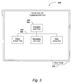
- FIG. 3 illustrates a screenshot of an exemplary embedded composite object that corresponds to an organizational chart in accordance with one embodiment of the present invention.
- Chart 300 is a type of graphical object that may be integrated in a host application as a composite object.
- the organizational chart example is a simple example that illustrates that difference between the semantic data of the object and the presentation data.
- the presentation data corresponds to the layout of the node elements (e.g., 302 ), or blocks, and the connectors (e.g., 304 ).
- the semantic data is the data included in the node elements and the relationship of the data. For example, the semantic data includes that the root node corresponds to the President, Jane Doe, while the other nodes correspond to other individuals that are child elements of the root node.
- the root/child relationship of the nodes is indicative of the hierarchical relationship of the individuals listed. Accordingly, the semantic data is data-driven, providing the relationship between individuals in the organization, while the presentation data concentrates on the layout and style used to display the relationship. With repeated shapes in the chart, much of the presentation data may be consolidated, with each node of chart 300 being linked to a single description of a shape that corresponds to all nodes and a description of single connector type. Previously, for some embedded object designs, an embedded object would simply be stored as an image. If a similar organizational chart included fifty nodes, then an image that corresponds to the data of all 50 nodes and 50 connectors would be stored. The file size of the embedded object could increase such that it is no longer usable depending on the amount of information included in the embedded object.
- the present invention allows the storage requirements for some particular composite objects to be significantly reduced when the composite objects have repeated shapes. There is also some possible size reduction with regard to style and richer graphic elements. For example, creating gradients, drop shadows, glow effects may have much smaller associated file sizes. Storage of the data corresponding to a composite object is described in greater detail below with relation to FIG. 4 .
- Chart 300 provides a simple example of one type of graphical object that lends itself to storage a composite object.
- Other object that take advantage of the composite object structure are bar charts, diagrams, tables, and other objects that may be described by a combination of shapes and text.
- Chart 300 also shows tab selector 310 that directs a user viewing the chart to a set of chart tools that are available for editing the chart.
- tab selector 310 appears when a user has selected chart 300 in the host application document for editing or other manipulation.
- the chart tools option provides the user with the functionality of the application that the chart was originally created in while in the host application. Accordingly, despite being located in another application document, a full range of composition options may be presented to the user for editing chart 300 directly in the host application.
- FIG. 4 shows a functional block diagram for an exemplary composite object storage structure that corresponds to an organizational chart in accordance with one embodiment of the present invention.
- Storage structure 400 includes both the stored semantic data and the stored presentation data.
- Storage structure 400 includes data source 410 , styles table 420 , and layout logic 430 .
- Data source 410 includes a listing of the nodes of an organizational chart (e.g., chart 300 of FIG. 3 ) and describes the parent/child relationship between the nodes. Data source 410 corresponds to the persisted, semantic data of the composite object.
- the structure of data source 410 is provided by way of example only, and the semantic data of the composite object may be stored in alternative formats such as multi-dimensional data structures, structured lists, or the like.
- Styles table 420 and layout logic 430 provide presentation for the composite object.
- Styles table 420 illustrates that the style of the nodes and connectors is defined according to a shapestyle definition that is pointed to by styles table 420 . In one embodiment, depending on the type of object, a user may be limited in the changes that can be performed to a style.
- Layout logic 430 provides a description of the layout of the nodes in the organizational chart. The structures of styles table 420 and layout logic 430 are provided by way of example only, and the presentation data of the composite object may be stored in alternative formats such as multi-dimensional data structures, structured lists, or the like.
- the composite object additionally includes a header that includes general information about the composite object.
- the header includes a uniform resource identifier (URI) for the composite object that describes the type of composite object and may therefore be used as a key to determine which composite object server should be invoked to load and handle the object data.
- URI uniform resource identifier
- the composite object includes a GVML or shapes XML description of the shapes of the composite object that provides a minimum visual tree of the composite object's shapes in case decomposing the data of the composite object fails.
- FIG. 5 illustrates a logical flow diagram of an exemplary process for loading a composite object in a host application document in accordance with one embodiment of the present invention.
- Process 500 starts at block 502 where one or more anchors that reference composite objects are included in the definition of a document in a host application.
- Process continues at block 504 .
- the document definition is read.
- the document definition may be written in XML or another language that may be used to describe a document.
- the document may be read to load the document into memory or output/render the document to an output device such as a monitor or printer.
- processing continues to decision block 506 .
- the anchor acts as a placeholder, defining the position of the composite object in the document. If no anchor is encountered, processing continues to block 516 where process 500 ends and the document may be loaded without any composite objects and/or processing may move on to other tasks. However, if an anchor is encountered, processing continues at block 508 .
- a server is selected that provides support for generating and storing the composite objects.
- the server refers to any computing device that is capable of processing the composite object, including the computing device storing the host application and document.
- the server is identified according to a uniform resource identifier (URI) included in a header portion of the composite object.
- URI uniform resource identifier
- the schema representing the composite object is also examined to determine an appropriate server. Processing continues at decision block 510 .
- the GVML is not provided as a fallback, but is instead included for composite objects that decide for themselves whether to leverage alternate content block features for providing GVML along with the full composite object structure. Stated differently, maintaining a GVML representation is not a requirement of a composite object, but an option left up to the composite object to select. Also, instead of designating a specific place to store GVML as part of the schema describing the composite object, a file format feature is provided to supply multiple representations of the object. If the composite object server is located, processing continues to block 514 .
- a load method is called on the composite object that passes to the composite object server the data corresponding to a definition of the composite object (e.g., an XML definition of the composite object).
- the passed data is parsed into to the semantic data and the presentation data for those composite objects that may separate their data accordingly.
- processing continues to block 516 , where process 500 ends and processing may move on to rendering a view of the composite object in the host application document or other tasks.
- FIG. 6 shows a logical flow diagram of an exemplary process for rendering a composite object in a view of a host application document in accordance with one embodiment of the present invention.
- Process 600 starts at block 602 where a composite object is loaded and a view is in the process of being generated for rendering the host application document as an output to a display, printer, or other output device. Processing continues at block 604 .
- a view interface (e.g., view interface 222 in FIG. 2 ) is implemented by the composite object server (e.g., composite object server 210 . Once implemented, the view interface is then owned by the view and may be used by the view for generation of view elements and editors corresponding to the composite object. Once the view interface is generated, processing continues at block 606 .
- the view elements corresponding to the host application and the composite objects within the host application are generated for rendering the view.
- the view elements include one or more view elements related to composite objects included in the host application document.
- the view elements are organized in a hierarchical tree structure that corresponds to the structure of the host application document.
- the view elements are generated by the view interface by combining the presentation and semantic data of the composite object into the view element.
- any target-specific parameters, or other customizations associated with that particular view are applied to the view.
- the view rendering may be dependent on the output device or other view data (e.g., currently zoomed, etc.).
- Other customizations may include rendering one or more of the view elements in black-and-white, or a variety of other selections corresponding to the view.
- the view is rendered.
- the shape properties of the view are translated into lower level graphics primitives.
- the lower level graphic primitives correspond to GEL (Graphics Effects Layer) paths generated from the translation.
- GEL Graphics Effects Layer
- a GEL factory then creates a meta-object that corresponds to the composite object embedded in the rendered view.
- the translated data is output to a target device (e.g., display screen, printer) using graphic services provided in accordance with the operating system (e.g. GDI+).
- FIG. 7 illustrates a logical flow diagram of an exemplary process for editing a composite object in a view of a host application document in accordance with one embodiment of the present invention.
- Process 700 starts at block 702 where a view of the host application document has been rendered and has been presented to the user on a screen or using another output. Processing continues at decision block 704 .
- the user event may correspond to keystrokes, mouse clicks, or other user inputs related to the host application document. If such a user event is not received, processing returns to decision block 704 to await the receipts of a user event. In contrast, if a user event is received, processing continues at decision block 706 .
- the user event may be unrelated to the host application document or any of the composite objects. If the user event is not intended for handling by the view, then processing returns to decision block 704 to await the receipt of another user event. However, if the user event is meant to be handled by the view, processing continues at decision block 708 .
- the view interface generates the editors for the composite objects on an “on demand” basis where the editor is not generated until needed. If the editor has not already been generated for the composite object being edited, processing moves to block 710 .
- the editor is generated by the view interface for editing the composite object. With the editor generated, or if the editor was previously generated, processing continues at block 712 .
- a selection is generated that corresponds to the editor created.
- the selection corresponds to aggregation of editor information with user event information.
- the editor also aggregates hit testing data with the other information to provide a more accurate determination of the objects in the rendered view being edited.
- commands or provided to the composite object server for editing the composite object are communicated to a command module that generates a set of commands for editing the composite object in response to the user event. These commands are then forward for operation on the composite object. With the composite object updated, processing continues to block 716 .
- a selection view element is generated that corresponds to the selection that was generated by the editor.
- the selection view element corresponds to any visualizations that correspond to the selection by the user within the composite object. For example, the user may have highlighted a string of text for editing.
- Selection view element is generated to provide the information for rendering the highlight of the text.
- Selection view element is complimentary to the other view elements of the view, but may not be necessary depending on the type of editing performed by the user.
- any target-specific parameters, or other customizations associated with that particular view are applied to the view.
- the view rendering may be dependent on the output device or other view data (e.g., currently zoomed, etc.).
- Other customizations may include rendering one or more of the view elements in black-and-white, or a variety of other selections corresponding to the view.
- the customizations are applied to both the view elements and any selection view elements generated.
- the view is re-rendered to include the editing to the composite object.
- the rendering is similar to the rendering described with relation to block 610 of FIG. 6 above.
- the re-rending of the view is similar to the original rendering of the view with the addition that the view now corresponds to the aggregate of any view elements, any changes to content of the composite object, and any selection view elements created.
- FIGS. 5-7 may be repeated as necessary, and may have their process steps rearranged, certain process steps deleted, or additional process steps added without departing from the spirit or scope of the invention.
Abstract
Description
Claims (19)
Priority Applications (4)
| Application Number | Priority Date | Filing Date | Title |
|---|---|---|---|
| US11/228,867 US7721205B2 (en) | 2005-09-15 | 2005-09-15 | Integration of composite objects in host applications |
| US11/479,983 US20070061351A1 (en) | 2005-09-13 | 2006-06-30 | Shape object text |
| US11/479,980 US20080263070A1 (en) | 2005-09-13 | 2006-06-30 | Common drawing objects |
| US11/479,982 US7783971B2 (en) | 2005-09-13 | 2006-06-30 | Graphic object themes |
Applications Claiming Priority (1)
| Application Number | Priority Date | Filing Date | Title |
|---|---|---|---|
| US11/228,867 US7721205B2 (en) | 2005-09-15 | 2005-09-15 | Integration of composite objects in host applications |
Related Child Applications (3)
| Application Number | Title | Priority Date | Filing Date |
|---|---|---|---|
| US11/228,617 Continuation-In-Part US8001526B2 (en) | 2005-09-13 | 2005-09-15 | Hierarchical property storage |
| US11/479,982 Continuation-In-Part US7783971B2 (en) | 2005-09-13 | 2006-06-30 | Graphic object themes |
| US11/479,983 Continuation-In-Part US20070061351A1 (en) | 2005-09-13 | 2006-06-30 | Shape object text |
Publications (2)
| Publication Number | Publication Date |
|---|---|
| US20070094607A1 US20070094607A1 (en) | 2007-04-26 |
| US7721205B2 true US7721205B2 (en) | 2010-05-18 |
Family
ID=37986694
Family Applications (1)
| Application Number | Title | Priority Date | Filing Date |
|---|---|---|---|
| US11/228,867 Expired - Fee Related US7721205B2 (en) | 2005-09-13 | 2005-09-15 | Integration of composite objects in host applications |
Country Status (1)
| Country | Link |
|---|---|
| US (1) | US7721205B2 (en) |
Cited By (6)
| Publication number | Priority date | Publication date | Assignee | Title |
|---|---|---|---|---|
| US20060107203A1 (en) * | 2004-11-15 | 2006-05-18 | Microsoft Corporation | Electronic document style matrix |
| US20070061343A1 (en) * | 2005-09-15 | 2007-03-15 | Microsoft Corporation | Hierarchical property storage |
| US20070061351A1 (en) * | 2005-09-13 | 2007-03-15 | Microsoft Corporation | Shape object text |
| US20070061349A1 (en) * | 2005-09-15 | 2007-03-15 | Microsoft Corporation | Hierarchically describing shapes |
| US20110055676A1 (en) * | 2009-08-28 | 2011-03-03 | Xingzhong Sun | Interactive user interface by embedding a document into a standardized object container |
| US20230325591A1 (en) * | 2022-04-12 | 2023-10-12 | Dell Products L.P. | Bundled and customizable documentation-viewer for application for increased asccessiblity |
Families Citing this family (23)
| Publication number | Priority date | Publication date | Assignee | Title |
|---|---|---|---|---|
| US7721205B2 (en) | 2005-09-15 | 2010-05-18 | Microsoft Corporation | Integration of composite objects in host applications |
| US7783971B2 (en) * | 2005-09-13 | 2010-08-24 | Microsoft Corporation | Graphic object themes |
| US8560942B2 (en) * | 2005-12-15 | 2013-10-15 | Microsoft Corporation | Determining document layout between different views |
| US8930812B2 (en) | 2006-02-17 | 2015-01-06 | Vmware, Inc. | System and method for embedding, editing, saving, and restoring objects within a browser window |
| US8078955B1 (en) * | 2006-05-02 | 2011-12-13 | Adobe Systems Incorportaed | Method and apparatus for defining table styles |
| US20070288883A1 (en) * | 2006-06-09 | 2007-12-13 | International Business Machines Corporation | Method for consolidated launching of multiple tasks |
| US7870536B2 (en) * | 2006-06-15 | 2011-01-11 | International Business Machines Corporation | Computer implemented method and system for sharing resources among hierarchical containers of resources |
| US8302073B2 (en) * | 2006-06-15 | 2012-10-30 | International Business Machines Corporation | Moving and copying dependencies along with source code |
| US10068189B2 (en) * | 2007-06-01 | 2018-09-04 | International Business Machines Corporation | Storing and depicting organizations that are subject to dynamic event driven restructuring |
| US20090119607A1 (en) * | 2007-11-02 | 2009-05-07 | Microsoft Corporation | Integration of disparate rendering platforms |
| US20110246913A1 (en) * | 2010-03-30 | 2011-10-06 | Microsoft Corporation | Automated User Interface Generator |
| US9069550B2 (en) * | 2010-11-29 | 2015-06-30 | International Business Machines Corporation | System and method for adjusting inactivity timeout settings on a display device |
| KR101415424B1 (en) * | 2011-03-02 | 2014-07-04 | 미쓰비시덴키 가부시키가이샤 | Programmable display apparatus and image data creation method |
| US11017165B2 (en) * | 2017-07-10 | 2021-05-25 | Adaptam Inc. | Methods and systems for connecting a spreadsheet to external data sources with temporal replication of cell blocks |
| US11698890B2 (en) | 2018-07-04 | 2023-07-11 | Monday.com Ltd. | System and method for generating a column-oriented data structure repository for columns of single data types |
| US20210149553A1 (en) | 2019-11-18 | 2021-05-20 | Monday.Com | Digital processing systems and methods for real-time resource and capacity allocation in collaborative work systems |
| US11829953B1 (en) | 2020-05-01 | 2023-11-28 | Monday.com Ltd. | Digital processing systems and methods for managing sprints using linked electronic boards |
| IL297858A (en) | 2020-05-01 | 2023-01-01 | Monday Com Ltd | Digital processing systems and methods for enhanced collaborative workflow and networking systems, methods, and devices |
| US11416526B2 (en) * | 2020-05-22 | 2022-08-16 | Sap Se | Editing and presenting structured data documents |
| US11928315B2 (en) | 2021-01-14 | 2024-03-12 | Monday.com Ltd. | Digital processing systems and methods for tagging extraction engine for generating new documents in collaborative work systems |
| US11741071B1 (en) | 2022-12-28 | 2023-08-29 | Monday.com Ltd. | Digital processing systems and methods for navigating and viewing displayed content |
| US11886683B1 (en) | 2022-12-30 | 2024-01-30 | Monday.com Ltd | Digital processing systems and methods for presenting board graphics |
| US11893381B1 (en) | 2023-02-21 | 2024-02-06 | Monday.com Ltd | Digital processing systems and methods for reducing file bundle sizes |
Citations (30)
| Publication number | Priority date | Publication date | Assignee | Title |
|---|---|---|---|---|
| US4498145A (en) | 1982-06-30 | 1985-02-05 | International Business Machines Corporation | Method for assuring atomicity of multi-row update operations in a database system |
| US5682468A (en) * | 1995-01-23 | 1997-10-28 | Intergraph Corporation | OLE for design and modeling |
| US5850507A (en) | 1996-03-19 | 1998-12-15 | Oracle Corporation | Method and apparatus for improved transaction recovery |
| US6282547B1 (en) | 1998-08-25 | 2001-08-28 | Informix Software, Inc. | Hyperlinked relational database visualization system |
| US6374251B1 (en) | 1998-03-17 | 2002-04-16 | Microsoft Corporation | Scalable system for clustering of large databases |
| US6380954B1 (en) * | 1998-02-09 | 2002-04-30 | Reuters, Ltd. | Method and system for layout of objects within a perimeter using constrained interactive search |
| US6493826B1 (en) | 1993-09-02 | 2002-12-10 | International Business Machines Corporation | Method and system for fault tolerant transaction-oriented data processing system |
| US6539396B1 (en) | 1999-08-31 | 2003-03-25 | Accenture Llp | Multi-object identifier system and method for information service pattern environment |
| US20030078913A1 (en) | 2001-03-02 | 2003-04-24 | Mcgreevy Michael W. | System, method and apparatus for conducting a keyterm search |
| US20030078935A1 (en) | 2001-05-16 | 2003-04-24 | Yoav Zibin | Method of encoding a dataset |
| US6618851B1 (en) | 1999-08-31 | 2003-09-09 | Autodesk, Inc. | Method and apparatus for state-reversion |
| US6654757B1 (en) | 1997-08-08 | 2003-11-25 | Prn Corporation | Digital System |
| US6711577B1 (en) | 2000-10-09 | 2004-03-23 | Battelle Memorial Institute | Data mining and visualization techniques |
| US6725421B1 (en) * | 1999-06-11 | 2004-04-20 | Liberate Technologies | Methods, apparatus, and systems for storing, retrieving and playing multimedia data |
| US6732090B2 (en) | 2001-08-13 | 2004-05-04 | Xerox Corporation | Meta-document management system with user definable personalities |
| US6772170B2 (en) | 1996-09-13 | 2004-08-03 | Battelle Memorial Institute | System and method for interpreting document contents |
| US6778979B2 (en) | 2001-08-13 | 2004-08-17 | Xerox Corporation | System for automatically generating queries |
| US20040220954A1 (en) | 2003-04-29 | 2004-11-04 | International Business Machines Corporation | Translation of data from a hierarchical data structure to a relational data structure |
| US6820075B2 (en) | 2001-08-13 | 2004-11-16 | Xerox Corporation | Document-centric system with auto-completion |
| US20040230888A1 (en) | 2003-05-13 | 2004-11-18 | Microsoft Corporation | Method and system for selectively enforcing presentation themes |
| US20050015729A1 (en) | 2000-04-06 | 2005-01-20 | Microsoft Corporation | Binary cache file format for themeing the visual appearance of a computer system |
| US20050171967A1 (en) | 2004-01-30 | 2005-08-04 | Paul Yuknewicz | System and method for exposing tasks in a development environment |
| US20050278625A1 (en) | 2004-06-15 | 2005-12-15 | Microsoft Corporation | Dynamic document and template previews |
| US20060230311A1 (en) | 2005-03-30 | 2006-10-12 | Microsoft Corporation | System and method for undoing application actions using inverse actions with atomic rollback |
| US20060242591A1 (en) | 2005-04-22 | 2006-10-26 | Microsoft Corporation | File dialog user interfaces and creation of same |
| US20070061343A1 (en) | 2005-09-15 | 2007-03-15 | Microsoft Corporation | Hierarchical property storage |
| US20070061351A1 (en) | 2005-09-13 | 2007-03-15 | Microsoft Corporation | Shape object text |
| US20070094607A1 (en) | 2005-09-15 | 2007-04-26 | Microsoft Corporation | Integration of composite objects in host applications |
| US20070106952A1 (en) | 2005-06-03 | 2007-05-10 | Apple Computer, Inc. | Presenting and managing clipped content |
| US20070174307A1 (en) | 2005-09-13 | 2007-07-26 | Microsoft Corporation | Graphic object themes |
-
2005
- 2005-09-15 US US11/228,867 patent/US7721205B2/en not_active Expired - Fee Related
Patent Citations (31)
| Publication number | Priority date | Publication date | Assignee | Title |
|---|---|---|---|---|
| US4498145A (en) | 1982-06-30 | 1985-02-05 | International Business Machines Corporation | Method for assuring atomicity of multi-row update operations in a database system |
| US6493826B1 (en) | 1993-09-02 | 2002-12-10 | International Business Machines Corporation | Method and system for fault tolerant transaction-oriented data processing system |
| US5682468A (en) * | 1995-01-23 | 1997-10-28 | Intergraph Corporation | OLE for design and modeling |
| US5850507A (en) | 1996-03-19 | 1998-12-15 | Oracle Corporation | Method and apparatus for improved transaction recovery |
| US6772170B2 (en) | 1996-09-13 | 2004-08-03 | Battelle Memorial Institute | System and method for interpreting document contents |
| US6654757B1 (en) | 1997-08-08 | 2003-11-25 | Prn Corporation | Digital System |
| US6380954B1 (en) * | 1998-02-09 | 2002-04-30 | Reuters, Ltd. | Method and system for layout of objects within a perimeter using constrained interactive search |
| US6374251B1 (en) | 1998-03-17 | 2002-04-16 | Microsoft Corporation | Scalable system for clustering of large databases |
| US6282547B1 (en) | 1998-08-25 | 2001-08-28 | Informix Software, Inc. | Hyperlinked relational database visualization system |
| US6725421B1 (en) * | 1999-06-11 | 2004-04-20 | Liberate Technologies | Methods, apparatus, and systems for storing, retrieving and playing multimedia data |
| US6539396B1 (en) | 1999-08-31 | 2003-03-25 | Accenture Llp | Multi-object identifier system and method for information service pattern environment |
| US6618851B1 (en) | 1999-08-31 | 2003-09-09 | Autodesk, Inc. | Method and apparatus for state-reversion |
| US20050015729A1 (en) | 2000-04-06 | 2005-01-20 | Microsoft Corporation | Binary cache file format for themeing the visual appearance of a computer system |
| US6711577B1 (en) | 2000-10-09 | 2004-03-23 | Battelle Memorial Institute | Data mining and visualization techniques |
| US20030078913A1 (en) | 2001-03-02 | 2003-04-24 | Mcgreevy Michael W. | System, method and apparatus for conducting a keyterm search |
| US20030078935A1 (en) | 2001-05-16 | 2003-04-24 | Yoav Zibin | Method of encoding a dataset |
| US6732090B2 (en) | 2001-08-13 | 2004-05-04 | Xerox Corporation | Meta-document management system with user definable personalities |
| US6820075B2 (en) | 2001-08-13 | 2004-11-16 | Xerox Corporation | Document-centric system with auto-completion |
| US6778979B2 (en) | 2001-08-13 | 2004-08-17 | Xerox Corporation | System for automatically generating queries |
| US20040220954A1 (en) | 2003-04-29 | 2004-11-04 | International Business Machines Corporation | Translation of data from a hierarchical data structure to a relational data structure |
| US20040230888A1 (en) | 2003-05-13 | 2004-11-18 | Microsoft Corporation | Method and system for selectively enforcing presentation themes |
| US20050171967A1 (en) | 2004-01-30 | 2005-08-04 | Paul Yuknewicz | System and method for exposing tasks in a development environment |
| US20050278625A1 (en) | 2004-06-15 | 2005-12-15 | Microsoft Corporation | Dynamic document and template previews |
| US20060230311A1 (en) | 2005-03-30 | 2006-10-12 | Microsoft Corporation | System and method for undoing application actions using inverse actions with atomic rollback |
| US7499955B2 (en) | 2005-03-30 | 2009-03-03 | Microsoft Corporation | System and method for undoing application actions using inverse actions with atomic rollback |
| US20060242591A1 (en) | 2005-04-22 | 2006-10-26 | Microsoft Corporation | File dialog user interfaces and creation of same |
| US20070106952A1 (en) | 2005-06-03 | 2007-05-10 | Apple Computer, Inc. | Presenting and managing clipped content |
| US20070061351A1 (en) | 2005-09-13 | 2007-03-15 | Microsoft Corporation | Shape object text |
| US20070174307A1 (en) | 2005-09-13 | 2007-07-26 | Microsoft Corporation | Graphic object themes |
| US20070061343A1 (en) | 2005-09-15 | 2007-03-15 | Microsoft Corporation | Hierarchical property storage |
| US20070094607A1 (en) | 2005-09-15 | 2007-04-26 | Microsoft Corporation | Integration of composite objects in host applications |
Cited By (8)
| Publication number | Priority date | Publication date | Assignee | Title |
|---|---|---|---|---|
| US20060107203A1 (en) * | 2004-11-15 | 2006-05-18 | Microsoft Corporation | Electronic document style matrix |
| US8631347B2 (en) | 2004-11-15 | 2014-01-14 | Microsoft Corporation | Electronic document style matrix |
| US20070061351A1 (en) * | 2005-09-13 | 2007-03-15 | Microsoft Corporation | Shape object text |
| US20070061343A1 (en) * | 2005-09-15 | 2007-03-15 | Microsoft Corporation | Hierarchical property storage |
| US20070061349A1 (en) * | 2005-09-15 | 2007-03-15 | Microsoft Corporation | Hierarchically describing shapes |
| US8001526B2 (en) | 2005-09-15 | 2011-08-16 | Microsoft Corporation | Hierarchical property storage |
| US20110055676A1 (en) * | 2009-08-28 | 2011-03-03 | Xingzhong Sun | Interactive user interface by embedding a document into a standardized object container |
| US20230325591A1 (en) * | 2022-04-12 | 2023-10-12 | Dell Products L.P. | Bundled and customizable documentation-viewer for application for increased asccessiblity |
Also Published As
| Publication number | Publication date |
|---|---|
| US20070094607A1 (en) | 2007-04-26 |
Similar Documents
| Publication | Publication Date | Title |
|---|---|---|
| US7721205B2 (en) | Integration of composite objects in host applications | |
| US8468441B2 (en) | Cross-application support of charts | |
| US9122669B2 (en) | Flat schema integrated document oriented templates | |
| US8578277B2 (en) | Integrating charts in documents | |
| US8799857B2 (en) | XML application framework | |
| US8793649B2 (en) | XML application framework | |
| JP4921785B2 (en) | Managing and using data in computer-generated documents | |
| RU2365978C2 (en) | Programming interface for computing platform | |
| US8806357B2 (en) | Plug-ins for editing templates in a business management system | |
| US7783971B2 (en) | Graphic object themes | |
| KR101578249B1 (en) | Automatic user interface generation for entity interaction | |
| US20060168557A1 (en) | Methods and apparatus for implementing model-based software solution development and integrated change management | |
| US20090006154A1 (en) | Declarative workflow designer | |
| JPWO2006137565A1 (en) | Document processing apparatus and document processing method | |
| US20100057760A1 (en) | Generic data retrieval | |
| JP2008508640A (en) | Document processing and management method for making changes to documents and their representation | |
| JPWO2006051905A1 (en) | Data processing apparatus and data processing method | |
| US7698636B2 (en) | System and method for in-context editing of components | |
| US20070083853A1 (en) | System and method for declarative validation rule editor | |
| US20070061349A1 (en) | Hierarchically describing shapes | |
| US7409642B2 (en) | Method and system for applying user interface elements to data | |
| JPWO2006051904A1 (en) | Data processing apparatus and data processing method | |
| JPWO2006051721A1 (en) | Document processing apparatus and document processing method | |
| US20080263070A1 (en) | Common drawing objects | |
| US20040205707A1 (en) | Logical separation of code and content |
Legal Events
| Date | Code | Title | Description |
|---|---|---|---|
| AS | Assignment |
Owner name: MICROSOFT CORPORATION,WASHINGTON Free format text: ASSIGNMENT OF ASSIGNORS INTEREST;ASSIGNORS:MORGAN, ASHLEY L.;LI, BARN-WAN;HUANG, KE-CHENG;AND OTHERS;SIGNING DATES FROM 20050831 TO 20050908;REEL/FRAME:016740/0858 Owner name: MICROSOFT CORPORATION, WASHINGTON Free format text: ASSIGNMENT OF ASSIGNORS INTEREST;ASSIGNORS:MORGAN, ASHLEY L.;LI, BARN-WAN;HUANG, KE-CHENG;AND OTHERS;REEL/FRAME:016740/0858;SIGNING DATES FROM 20050831 TO 20050908 |
|
| STCF | Information on status: patent grant |
Free format text: PATENTED CASE |
|
| FPAY | Fee payment |
Year of fee payment: 4 |
|
| AS | Assignment |
Owner name: MICROSOFT TECHNOLOGY LICENSING, LLC, WASHINGTON Free format text: ASSIGNMENT OF ASSIGNORS INTEREST;ASSIGNOR:MICROSOFT CORPORATION;REEL/FRAME:034543/0001 Effective date: 20141014 |
|
| MAFP | Maintenance fee payment |
Free format text: PAYMENT OF MAINTENANCE FEE, 8TH YEAR, LARGE ENTITY (ORIGINAL EVENT CODE: M1552) Year of fee payment: 8 |
|
| FEPP | Fee payment procedure |
Free format text: MAINTENANCE FEE REMINDER MAILED (ORIGINAL EVENT CODE: REM.); ENTITY STATUS OF PATENT OWNER: LARGE ENTITY |
|
| LAPS | Lapse for failure to pay maintenance fees |
Free format text: PATENT EXPIRED FOR FAILURE TO PAY MAINTENANCE FEES (ORIGINAL EVENT CODE: EXP.); ENTITY STATUS OF PATENT OWNER: LARGE ENTITY |
|
| STCH | Information on status: patent discontinuation |
Free format text: PATENT EXPIRED DUE TO NONPAYMENT OF MAINTENANCE FEES UNDER 37 CFR 1.362 |
|
| FP | Lapsed due to failure to pay maintenance fee |
Effective date: 20220518 |