US7593755B2 - Display of wireless data - Google Patents

Display of wireless data Download PDF

Info

Publication number
US7593755B2
US7593755B2 US10/941,374 US94137404A US7593755B2 US 7593755 B2 US7593755 B2 US 7593755B2 US 94137404 A US94137404 A US 94137404A US 7593755 B2 US7593755 B2 US 7593755B2
Authority
US
United States
Prior art keywords
mechanical
display
information
indicator
available public
Prior art date
Legal status (The legal status is an assumption and is not a legal conclusion. Google has not performed a legal analysis and makes no representation as to the accuracy of the status listed.)
Expired - Fee Related, expires
Application number
US10/941,374
Other versions
US20060073851A1 (en
Inventor
Christian J. Colando
Albert W. Tan
Dane M. Howard
Lorenzo Tessiore
Eric Glenn Lang
Current Assignee (The listed assignees may be inaccurate. Google has not performed a legal analysis and makes no representation or warranty as to the accuracy of the list.)
Microsoft Technology Licensing LLC
Original Assignee
Microsoft Corp
Priority date (The priority date is an assumption and is not a legal conclusion. Google has not performed a legal analysis and makes no representation as to the accuracy of the date listed.)
Filing date
Publication date
Application filed by Microsoft Corp filed Critical Microsoft Corp
Priority to US10/941,374 priority Critical patent/US7593755B2/en
Assigned to MICROSOFT CORPORATION reassignment MICROSOFT CORPORATION ASSIGNMENT OF ASSIGNORS INTEREST (SEE DOCUMENT FOR DETAILS). Assignors: HOWARD, DANE M., COLANDO, CHRISTIAN J., LANG, ERIC G., TAN, ALBERT W., TESSIORE, LORENZO
Priority to JP2005268495A priority patent/JP2006101505A/en
Priority to CNA2005101099231A priority patent/CN1758548A/en
Priority to KR1020050086412A priority patent/KR101122937B1/en
Priority to EP05108477A priority patent/EP1637969A3/en
Publication of US20060073851A1 publication Critical patent/US20060073851A1/en
Publication of US7593755B2 publication Critical patent/US7593755B2/en
Application granted granted Critical
Assigned to MICROSOFT TECHNOLOGY LICENSING, LLC reassignment MICROSOFT TECHNOLOGY LICENSING, LLC ASSIGNMENT OF ASSIGNORS INTEREST (SEE DOCUMENT FOR DETAILS). Assignors: MICROSOFT CORPORATION
Expired - Fee Related legal-status Critical Current
Adjusted expiration legal-status Critical

Links

Images

Classifications

    • HELECTRICITY
    • H04ELECTRIC COMMUNICATION TECHNIQUE
    • H04BTRANSMISSION
    • H04B1/00Details of transmission systems, not covered by a single one of groups H04B3/00 - H04B13/00; Details of transmission systems not characterised by the medium used for transmission
    • H04B1/38Transceivers, i.e. devices in which transmitter and receiver form a structural unit and in which at least one part is used for functions of transmitting and receiving
    • H04B1/40Circuits
    • GPHYSICS
    • G04HOROLOGY
    • G04GELECTRONIC TIME-PIECES
    • G04G9/00Visual time or date indication means
    • G04G9/0064Visual time or date indication means in which functions not related to time can be displayed
    • GPHYSICS
    • G04HOROLOGY
    • G04GELECTRONIC TIME-PIECES
    • G04G21/00Input or output devices integrated in time-pieces
    • G04G21/04Input or output devices integrated in time-pieces using radio waves
    • GPHYSICS
    • G06COMPUTING; CALCULATING OR COUNTING
    • G06FELECTRIC DIGITAL DATA PROCESSING
    • G06F1/00Details not covered by groups G06F3/00 - G06F13/00 and G06F21/00
    • G06F1/16Constructional details or arrangements
    • G06F1/1613Constructional details or arrangements for portable computers
    • G06F1/163Wearable computers, e.g. on a belt
    • GPHYSICS
    • G06COMPUTING; CALCULATING OR COUNTING
    • G06FELECTRIC DIGITAL DATA PROCESSING
    • G06F1/00Details not covered by groups G06F3/00 - G06F13/00 and G06F21/00
    • G06F1/16Constructional details or arrangements
    • G06F1/1613Constructional details or arrangements for portable computers
    • G06F1/1633Constructional details or arrangements of portable computers not specific to the type of enclosures covered by groups G06F1/1615 - G06F1/1626
    • G06F1/1637Details related to the display arrangement, including those related to the mounting of the display in the housing
    • GPHYSICS
    • G06COMPUTING; CALCULATING OR COUNTING
    • G06FELECTRIC DIGITAL DATA PROCESSING
    • G06F1/00Details not covered by groups G06F3/00 - G06F13/00 and G06F21/00
    • G06F1/16Constructional details or arrangements
    • G06F1/1613Constructional details or arrangements for portable computers
    • G06F1/1633Constructional details or arrangements of portable computers not specific to the type of enclosures covered by groups G06F1/1615 - G06F1/1626
    • G06F1/1684Constructional details or arrangements related to integrated I/O peripherals not covered by groups G06F1/1635 - G06F1/1675
    • G06F1/1698Constructional details or arrangements related to integrated I/O peripherals not covered by groups G06F1/1635 - G06F1/1675 the I/O peripheral being a sending/receiving arrangement to establish a cordless communication link, e.g. radio or infrared link, integrated cellular phone
    • HELECTRICITY
    • H04ELECTRIC COMMUNICATION TECHNIQUE
    • H04WWIRELESS COMMUNICATION NETWORKS
    • H04W84/00Network topologies
    • H04W84/02Hierarchically pre-organised networks, e.g. paging networks, cellular networks, WLAN [Wireless Local Area Network] or WLL [Wireless Local Loop]
    • H04W84/10Small scale networks; Flat hierarchical networks
    • H04W84/16WPBX [Wireless Private Branch Exchange]

Definitions

  • the present invention relates generally to portable electronic devices. More particularly, the present invention relates to a device and method for collecting and displaying wireless data.
  • Smart Personal Objects are everyday objects, such as clocks, pens, key-chains and billfolds, that are made smarter, more personalized and more useful through the use of special software. These everyday objects already exist in huge numbers, and, of course, all of them already have primary functions that people find valuable. They could also be extended to display not just time, but timely information—traffic information, schedule updates, news—anything that is time-critical and useful to people.
  • a battery-powered, portable computer such as watch device, is provided for receiving wireless transmissions and displaying information based at least in part on information contained in the wireless transmissions.
  • the invention provides a device which allows device manufacturers a high degree of customization to display smart personal object data, thereby catering to higher-end brands and the related consumer base.
  • the device receives and processes information from a wireless transmission.
  • the device includes one or more mechanical indicators for displaying the information received via the wireless transmission.
  • the device operates to display information using a mechanical indicators or some combination of digital and mechanical indicators.
  • Various mechanical indicators may be used for conveying the information to a user such as hands, sliders, dials, rings, disks, etc. for example.
  • information may be conveyed using various mechanical indicators coupled with one or more digital displays (i.e. LEDs, LCDs, etc.).
  • the device can be constructed in traditional high fidelity/quality.
  • devices may be wrist-worn watches specially configured to receive transmissions from broadcast towers, or other signal transmission systems/devices.
  • a device such as a watch device, having a more elegant style and look, may display information received from a wireless transmission.
  • FIG. 1 is a diagram illustrating an operating environment
  • FIG. 2 is a schematic diagram illustrating an electronic device
  • FIG. 3A depicts a watch device according to an embodiment of the invention
  • FIG. 3B depicts a watch device according to another embodiment of the invention.
  • FIG. 4A is a diagram illustrating a watch device and related components
  • FIG. 4B is a functional block diagram of a watch device according to an embodiment of the invention.
  • FIGS. 5A and 5B depict a watch device according to another embodiment of the invention.
  • FIG. 6 depicts a watch device according to another embodiment of the invention.
  • FIGS. 7A and 7B depict a watch device according to yet another embodiment of the invention.
  • FIG. 8 depicts a watch device according to an embodiment of the invention.
  • FIGS. 9A and 9B depict a watch device according to another embodiment of the invention.
  • FIG. 10 depicts a watch device according to an embodiment of the invention.
  • FIG. 11 illustrates various alternative embodiments of the invention.
  • the present invention is described in the context of a wireless communication device for receiving and displaying information.
  • the devices may be watch type devices that are specially configured to receive communication signals, as is described in greater detail below.
  • the devices display information using mechanical elements or mechanical elements coupled with digital indicators, based at least in part upon received wireless signals transmitted from a source. Minor deviations from the described embodiments will also become apparent without departing from the spirit of the invention.
  • Computer readable media can be any available media that can be accessed by client/server devices.
  • Computer readable media may comprise computer storage media and communication media.
  • Computer storage media includes volatile and nonvolatile, removable and non-removable media implemented in any method or technology for storage of information such as computer readable instructions, data structures, program modules or other data.
  • Computer storage media includes, but is not limited to, RAM, ROM, EEPROM, flash memory or other memory technology, CD-ROM, digital versatile disks (DVD) or other optical storage, magnetic cassettes, magnetic tape, magnetic disk storage or other magnetic storage devices, or any other medium which can be used to store the desired information and which can be accessed by client/server devices.
  • Communication media typically embodies computer readable instructions, data structures, program modules or other data in a modulated data signal such as a carrier wave or other transport mechanism and includes any information delivery media.
  • modulated data signal means a signal that has one or more of its characteristics set or changed in such a manner as to encode information in the signal.
  • communication media includes wired media such as a wired network or direct-wired connection, and wireless media such as acoustic, RF, infrared and other wireless media. Combinations of any of the above are included within the scope of computer readable media.
  • content can be any information that may be stored in an electronic device.
  • content may comprise graphical information, textual information, and any combination of graphical and textual information.
  • Content may be displayable information or auditory information. Auditory information may comprise a single sound or a stream of sounds.
  • FIG. 1 illustrates an example operating environment 100 for the present invention.
  • an FM signal or broadcast is transmitted over a communication channel 110 to various electronic devices.
  • Example electronic devices that have an FM receiver or transceiver may include a desktop computer, a watch, a portable computer, a wireless cellular telephone (cell phone), and/or a personal data assistant (PDA).
  • the electronic devices are arranged to receive information from the FM broadcast.
  • the FM broadcast may be of any number of types including but not limited to: a standard FM transmission, a sub-carrier FM transmission, or any other type of FM transmission as may be desired.
  • Example electronic devices that may include an electronic system that is arranged to operate according to the interaction model are illustrated in FIG. 1 .
  • the electronic system may employ a wireless interface such as the FM transmission systems that are described above.
  • Each of the electronic systems receives messages/information over the communication channel.
  • Each broadcast transmission corresponds to the transmission of one or more frames.
  • Each frame may include multiple messages, where some messages are public broadcast (aka “global” or “shared” messages), while other messages are client specific messages (aka “personal” or “private” messages). Every client that is located within the designated service region may receive shared messages, while a single client may decode a private message.
  • Electronic devices receive message packets according to shared and private messages that are directed to the client device.
  • Message packets are organized in groups according to logical slot (or channel) entry numbers. For example, a particular electronic device is configured to receive a selected group of channels from the available channels.
  • the message packets associated with each of those channels is received, processed, and stored in the client device.
  • the stored message packets can be reviewed using a user interface that employs an interaction model, in accordance with the present invention.
  • Example channels include: a time channel, a messages channel, a contact channel, a calendar channel, a weather channel, a stocks channel, a news channel, sports, and/or a games channel.
  • Messages associated with each channel include message content that is based on the particulars of the channel.
  • the weather channel may include the current weather in a local region, the current weather in a national region, and the current weather in an international region.
  • FIG. 2 is a schematic diagram illustrating functional components of an illustrative electronic device 200 .
  • the electronic device 200 has a processor 260 , a memory 262 , a display 228 , and a user interface 232 .
  • the memory 262 generally includes both volatile memory (e.g., RAM) and non-volatile memory (e.g., ROM, Flash Memory, or the like).
  • the electronic device 200 includes an operating system 264 , such as the Windows CE operating system from Microsoft Corporation or another operating system, which is resident in the memory 262 and executes on the processor 260 .
  • the user interface 232 may be a series of push buttons, a scroll wheel, a numeric dialing pad (such as on a typical telephone), or another type of user interface means.
  • the display 228 may be a liquid crystal display, a multiple bit display, a mechanical display, a hybrid display, or a full color display or any other type of display commonly used in electronic devices.
  • the display 228 may be touch-sensitive that would act as an input device.
  • One or more application programs 266 are loaded into memory 262 and run on the operating system 264 .
  • Examples of application programs include phone dialer programs, email programs, scheduling/calendaring programs, PIM (personal information management) programs, Internet browser programs, and so forth.
  • the electronic device 200 also includes a non-volatile storage 268 that is located within the memory 262 .
  • the non-volatile storage 268 may be used to store persistent information which should not be lost if the electronic device 200 is powered down.
  • the applications 266 may use and store information in the storage 268 , such as e-mail or other messages used by an e-mail application, contact information used by a PIM, appointment information used by a scheduling program, documents used by a word processing application, and the like.
  • the electronic device 200 has a power supply 270 , which may be implemented as one or more batteries.
  • the power supply 270 might further include an external power source, such as an AC adapter or a powered docking cradle that supplements or recharges the batteries.
  • the electronic device 200 is also shown with various types of external notification mechanisms: one or more light-emitting diodes (LEDs) 240 , an audio interface 274 , a tactile interface 276 , and one or more mechanical elements 278 included as part of the display 228 .
  • LEDs light-emitting diodes
  • the LEDs 240 may be programmed to remain on indefinitely until the user takes action to indicate the powered-on status of the device.
  • the audio interface 274 is used to provide audible signals to and receive audible signals from the user.
  • the audio interface 274 may be coupled to a speaker for providing audible output and to a microphone for receiving audible input, such as to facilitate a telephone conversation, or as a user interface using voice recognition.
  • a vibration device can be used to give feedback to the user such as for alerting the user of a newly arrived message and/or other information.
  • the electronic device 200 may control each alert mechanism separately (e.g., audio, vibration, as well as visual cues).
  • the electronic device 200 also includes a radio interface layer 272 that performs the function of receiving and/or transmitting radio frequency communications.
  • the radio interface layer 272 facilitates wireless connectivity between the electronic device 200 and the outside world, via a communications carrier or service provider. Transmissions to and from the radio interface layer 272 are conducted under control of the operating system 264 . In other words, communications received by the radio interface layer 272 may be disseminated to application programs 266 via the operating system 264 , and vice versa (described below).
  • electronic device 200 is a mobile electronic device such as a watch device that includes a wireless interface.
  • exemplary user interfaces for a watch device are shown in FIGS. 3A and 3B , as will be described below.
  • the below-described user interface configurations include multiple selector buttons (e.g., four selector buttons), the functions of many of the selector buttons may be combined by a single selector (e.g., a button, a rocket switch, a wheel, etc.).
  • FIG. 3A illustrates an exemplary watch device 300 that includes a user interface to an electronic system that is configured to operate in accordance with the present invention.
  • the watch device 300 includes a bezel 302 , which has an electronic system (e.g., see FIG. 2 and FIG. 4 below).
  • the bezel 302 has an analog and/or digital display 304 .
  • the bezel includes analog-type watch hands 306 a - c for tracking hours, minutes, and seconds. In alternative embodiments, the watch hands may be used to track or draw attention to other information.
  • the watch device 300 includes a series of selectors 308 a - c that are arranged to operate as a user interface (UI). Selector 308 c operates according to both translational and rotational movement, allowing multiple functions to be performed, as described further below. Each selector may be implemented to have default function, and/or a context determined function. The currently selected channel determines the context for each selector.
  • the electronic watch device 300 is context sensitive in that the function that is associated with each selector may change based on the selected channel or display screen.
  • a first one of the selectors 308 a may control a first analog and/or digital display 310 .
  • the display 310 is an analog display.
  • analog display refers to indicating information using mechanical indicators.
  • the analog display of FIG. 3A includes a gradated area having a plurality of “tick” marks, including “positive” and “negative” indicators. Each tick mark may be used to indicate a greater or lesser quantity, status, or amount.
  • the analog display further includes a pointer 312 for pointing to a tick mark, based on the wireless information received and processed by the device 300 .
  • a second one for the selectors 308 b may control a second analog and/or digital display 314 .
  • display 314 is a digital display, depicting a stock indicator as the selected current channel.
  • the device 300 includes a variety of current channel indicators which can be displayed on the digital display 314 .
  • FIG. 3A depicts that a stock channel is the current channel, wherein no change has occurred heretofore based on the “zero” indication of the analog display 310 .
  • a positive change in the stock channel such as NASDAQ for example, is indicated when the pointer 312 is pointing to the positive side of the analog display.
  • a negative change in the stock channel is indicated when the pointer 312 is pointing to the negative side of the analog display.
  • activation of selector 308 a can reset the display to a default setting.
  • activating selector 308 a may page up from a current displayed event/category to a previous event/category.
  • the resetting of the display 310 may be accomplished by activating the first selector for a predetermined time period. For example, when the selector is a button as shown in FIG. 3A , the button is held for a timeout interval such as two seconds before the setting function is activated.
  • activating selector 308 b may page down from a current displayed event/category to a next event/category.
  • a backlighting function may be utilized when both selectors 308 a - b are simultaneously depressed for a predetermined interval.
  • a third one of the selectors 308 c is to control various aspects of the device including controlling the analog hands 306 a - c .
  • the third selector may be retracted from the bezel to a plurality of positions. At each position, the third selector may be rotated clockwise or counter-clockwise to control certain functions.
  • One of the third selector positional states may also operate to control one or more analog/digital displays. That is, the third selector may be configured as a “master” selector, operable to control all functional aspects of the watch device 300 .
  • the third selector 308 c may also have an alternate function based on the currently selected channel (a stock channel, for example) or display.
  • the third selector is activated by retracting the selector to a first position with respect to the bezel and rotating the selector in a clockwise manner for a predetermined time interval (e.g., two seconds) to select a main channel or “primary” channel (a stock channel, for this example).
  • a predetermined time interval e.g., two seconds
  • the selectors are arranged such that the electronic device accomplishes navigating and selecting content on a channel in a simple manner.
  • Selectors 308 a - c may also be replaced with a wheel type of device.
  • the functions of the selectors may be activated by rotating the wheel device in a counterclockwise and/or clockwise manner and/or by pressing the wheel device towards the watch bezel. It will be appreciated that other examples of selector mechanisms may be employed and the present invention is not intended to be limited to any specific examples/embodiments described herein.
  • a device for receiving and processing a wireless signal, preferably a radio signal, transmitted by a source.
  • the device is operable to display various information extracted from the wireless signal.
  • the device is operable to receive “real-time” information, such as stock, sports, weather, and other information and to display the information using, in part or solely, analog (mechanical) indicator mechanisms.
  • the invention provides a solution for consumers who are unwilling to use or wear wireless electronic devices due to inelegant or undesirable display characteristics of the devices. For example, certain watch consumers will not wear watches that do not have certain user-oriented characteristics, such as quartz displays, chronograph features, perpetual calendars, kinetic winding, etc. Other users are dissatisfied with the rather inelegant digital displays associated with many electronic watch and other products.
  • the present invention provides solutions to these and other problems associated with consumer satisfaction and preference. However, it will be appreciated that the present invention is not limited to watch devices, and those skilled in the art will realize the benefits of the present invention for other mobile electronic devices.
  • FIG. 4A yet another exemplary watch device 400 is shown in FIG. 4A .
  • the watch device 400 includes an electronic system 402 that is configured to operate in accordance with the present invention.
  • the watch device 400 includes a watchband 404 that includes an antenna that is either attached to the watchband or integrally formed within the watchband 404 .
  • the antenna is coupled to the electronic system 402 contained in the watch.
  • the electronic system 402 may be contained in the bezel as shown in FIG. 4A , or in some other portion of the watch device.
  • the electronic system 402 is a computer-based system, including functionality of operating as either a receiver and/or transceiver type of device. As illustrated in the figure, the electronic system includes a transceiver 406 , a microcomputer unit or microprocessor 408 , and an analog radio 410 . The antenna connects to, and is controlled by, the transceiver 406 . Transactions between the microprocessor 408 and the radio components are mediated over a microprocessor-digital transceiver interface. The components of the watch device 400 are housed in a watch-sized enclosure and rely on battery power for operation.
  • the transceiver 406 generally includes a digital signal processor (DSP) 412 , which performs control, scheduling, and post-processing tasks for the transceiver, and a real-time device (RTD) 414 , which includes a digital radio, system timing, and real-time event dispatching.
  • DSP digital signal processor
  • RTD real-time device
  • the DSP 412 is coupled to the microprocessor 408 , and transceiver tasks are commanded by the microprocessor 408 .
  • One of the DSP's tasks may process received data for such purposes as sub-carrier phase recovery, baud recovery and/or tracking, compensation for fading effects, demodulation, de-interleaving, channel state estimation and error-correction.
  • the post-processing of packets may occur when an entire packet has been received, or another subsequent time.
  • the DSP 412 analyzes the transmitted data packets to determine a broadcast station's signal timing with respect to a local clock of the RTD 414 .
  • the local clock is synchronized with the transmitter's clock signal to maintain signal sampling integrity.
  • the receiver is periodically brought into symbol synchronization with the transmitter to minimize misreading of the received data.
  • the digital section of the RTD 414 may include system time-base generators, such as a crystal oscillator that provides a system clock for the microprocessor 408 and the DSP 412 .
  • the time-base also provides baud and sample timing for transmit and receive operations, start/stop control for radio operation, and controls the periods of clock suspension, when required.
  • the RTD 414 also performs radio operations, and may perform additional operations as well.
  • the radio 410 is arranged to receive segments of data that is arranged in packets.
  • the user interface is configured as a means for selecting one or more services.
  • a wireless client device user interacts with the user interface to select services such as news, stock prices, weather, and other features such as a personal calendar, address book, and the like.
  • Selected services are entered in a database for broadcast transmission at a later time.
  • the scheduling interface communicates with the broadcast server to begin a transmission sequence of data for the selected services.
  • the broadcast server subsequently formats the data for reception by one or more wireless client device, queues the data for transmission, and communicates the queued data to the FM broadcast tower for transmission.
  • the scheduling interface communicates the selected services to the broadcast server.
  • the broadcast server schedules the time interval for transmission of the selected service.
  • Each broadcast transmission corresponds to the transmission of one or more frames that are arranged in accordance with a frame protocol.
  • Each frame may include multiple messages, where some messages are public broadcast (aka “global” or “shared” messages), while other messages are client specific messages (aka “personal” or “private” messages).
  • Each frame includes a table of contents that indicates the extent of messages that are found within the next transmitted frame. Every client that is located within the designated service region may receive shared messages, while a single client may decode a private message.
  • Each frame includes a header, a table of contents, and a message payload that includes the content for one or more selected services as previously described.
  • the header also includes other information such as authentication data, identified service region, language, available stations for the identified service region, frame number, and time stamp.
  • Control information may also be included in one of the headers to indicate broadcast conditions such as a change in available channels, an assignment of a service region to a particular wireless client device, and an assignment of a particular channel (frequency).
  • each frame includes a change counter in one of the headers to indicate a change has taken place in the system. Wireless client devices (clients) may use the change counter to determine when to initiate a failover (when a broadcast tower becomes unavailable).
  • Client devices may be organized in a series of layers that are similar to the OSI networking model.
  • the layers include a physical layer, a link layer, a network layer, a transport layer, and an application layer.
  • the physical layer receives the FM subcarrier transmitted information and provides symbols to the link layer.
  • the link layer divides the symbols into segments, and handles viterbi coding, data whitening, and interleaving functions.
  • the network layer receives the segments and creates logical packets.
  • the network layer also handles cyclic redundancy check (CRC), encryption, and Reed-Solomon coding.
  • the transport layer decodes the logical packets to retrieve a table of contents (TOC), and includes data handlers that handle communication to the application layer.
  • the application layer includes a series of applications that are resident on the client device, and associated with subscriptions to broadcast services.
  • the transport layer maintains the data handlers for each registered application, and retrieves the TOC from the logical packets that are received from the network layer.
  • the transport layer notifies the registered applications that data streams will be available in the next frame transmission as identified with the service ID.
  • Each application program applies a series of metrics to determine priority for the receipt of data streams, which are submitted to the transport layer in the client device. Prioritization is performed independently by each application on the client device based on any criteria such as preferred data, error correction requirements, as well as base and elevated priority levels.
  • the transport layer reviews all of the requests, decides which requests will be accepted, and translates the accepted requests into packet requests to the network layer.
  • the network layer retrieves the relevant packets in the next frame transmission and passes the packets to the relevant registered applications via the data handlers.
  • a functional block diagram of a wireless client device 420 is shown.
  • the client devices offer a flexible and customizable programming environment, based on .NET Framework standard languages, mainly C#, for example.
  • the devices execute intermediate language (IL) produced by the existing and commercially available .NET compilers.
  • Applications may use and extend the various libraries; a Shell Library 422 and a Hardware library 424 , for example.
  • the Shell library 422 and Hardware 424 library collaborate to format information received not only from a user's input, but also received wireless signals.
  • the device presents the formatted information to the user leveraging various mechanical and/or electrical mechanisms, described below.
  • the lowest layer in the architecture is the Mechanical/Electrical layer 426 and operates to, among other things, gather raw input from the wireless signals, here the received FM transmission and/or the user.
  • This layer 426 also operates to present a user with formatted information in response to raw input and/or the user interaction itself.
  • the mechanical or analog display outputs require a mechanical to electrical built in conversion whose result is going to be handled by a Hardware Abstraction Layer (HAL) 428 .
  • HAL layer 428 serves as an interface layer between raw electrical signals and bit encoded information.
  • the HAL layer 428 offers generalization over underlying hardware, so that different hardware components that present similar characteristics can be treated in a homogeneous way by the Common Language runtime (CLR) layer 430 .
  • CLR Common Language runtime
  • the CLR layer 430 manages the execution of the application and provides all the services and type system implementation for executing standard IL language.
  • the CLR and HAL layers 430 and 428 respectively, interact to provide an operating system (OS) environment for application programming and execution.
  • the CLR layer 430 convoys and consolidates hardware events to and from the HAL layer 428 and exposes them for consumption to the libraries layer 432 , as well as gathering various events from library layers calls.
  • libraries are implemented in high NET framework languages and are compiled into IL code.
  • Libraries are object oriented APIs and are the only layer exposed to application programmers, offering a safe execution environment.
  • the device 420 utilizes a number of libraries including Hardware libraries and managed driver libraries offering an object oriented API capable of driving the underlying hardware while listening and reacting to the hardware events, such as a button press or a wireless signal capture event.
  • the libraries and drivers may be extended to fit to various H/W characteristics.
  • each client device includes a processor having an ARM 7 (or 9 ) core with additional functionalities such as: general purpose I/O (GpIO), VTU (Versatile Timer Unit); SPI and others features meant to drive and communicate with hardware; VTU exposes distinct Pulse Width Modulation (PWM) functionalities as well as input capture functionalities.
  • the external hardware including the various analog (mechanical) indicators described herein, is abstracted into a set of objects in the Shell 422 and H/W 424 libraries. Those objects expose the feature of interest of the H/W to the managed application and leverage the processor capabilities to communicate and drive the hardware.
  • the hardware and the application preferably provide 2 way interaction: the application can collect data from the H/W by mean of both push and pull mechanisms and can force H/W to enter a particular state, therefore driving it.
  • the communication to and from the hardware layer 432 and the application layer 434 is bidirectional built on top of the API object model.
  • Application inputs though the H/W may consist of user input and wireless signal data received over the wireless signal channel, radio for example, or through a connection (COM or USB) to a host PC or again through direct user input.
  • the output of the application consist of elaborated data directed to an application running on the host PC or to the electrical and/or mechanical media designed to present the user with the information.
  • the object API and its interaction with the CLR and the underlying HAL layer allow the application programmer to express the information with a very wide variety of mechanisms.
  • the presentation layer may use visual, tactile and acoustic mechanisms which may be electrical or mechanical, LED and LCD displays, hands, dials, rings, disks and in general any motion or motionless mechanism that can be driven out of an electrical modulated source and produce a tactile, visible, and/or acoustic feedback.
  • visual, tactile and acoustic mechanisms which may be electrical or mechanical, LED and LCD displays, hands, dials, rings, disks and in general any motion or motionless mechanism that can be driven out of an electrical modulated source and produce a tactile, visible, and/or acoustic feedback.
  • the mechanisms are programmable by controlling the production and modulation of an electrical signal from the object API layer.
  • one implementation uses general API capable of driving the GpIO and VTU circuits of the core or by using more sophisticated and peculiar drivers that may use those underlying APIs or call directly into special purpose routines in the CLR and HAL layers.
  • the libraries are designed to allow both push and pull programming paradigm: the CLR layer can call back into the libraries in response to a H/W event or libraries can poll the CLR layer 430 which in turn polls the HAL layer 428 to extract the H/W state and act upon a change.
  • a watch device 300 is shown displaying information received from a wireless signal, a signal broadcast over a FM channel, for example.
  • the watch device 300 is preferable to many consumers due to the refined and traditionally elegant appearance.
  • the watch device 300 may include a combined analog and/or mechanical display for displaying a category or context and/or a value indication.
  • a user of the watch has set the watch to a stock information channel using one of the selectors 308 described above.
  • the stock information channel may be included as a default channel based on user preference.
  • the watch device 300 includes analog or mechanical display features 310 and/or a digital display 314 for displaying information received from wireless signals transmitted from a radio-frequency (RF) driven source, preferably a frequency modulated source.
  • the information contained in the wireless signals may include stock information, sports information, weather information, and other desired user information.
  • the inventive watch device allows information received from wireless signals to be conveyed to a user using the analog and/or mechanical display features, described in detail below.
  • a watch device 300 includes an analog display 310 for conveying information received from a wireless signal. For this example, information is also conveyed via the digital display 314 .
  • the two displays 310 and 314 convey information to a user based upon a currently selected channel. The user, using the user interface, may select the current channel for display. The user may also select an update rate for updating the display.
  • the device 300 includes timing mechanisms for receiving wireless signals and disseminating information from the signals. The timing mechanisms may be adjusted according to user preference.
  • channels may be automatically displayed as part of a rotating schedule.
  • the analog and digital displays 310 and 314 may update and convey stock information based a stock channel transmission for a predetermined time period. It is also possible to independently update each display. After the predetermined time period, two minutes for example, the analog and digital displays 310 and 314 may convey sports-related information based a sport channel transmission for a predetermined time period, which may be a different period as compared to other display periods.
  • the timing and update features are applicable to the embodiments discussed below.
  • the watch device 300 is currently receiving wireless broadcast transmissions from a stock channel.
  • An informational icon 316 a stock channel indicator for this particular example, alerts the user of the watch device 300 that the current channel is the stock channel. That is, a stock information icon 316 is displayed in the digital display 314 , providing context to the user of the device 300 .
  • the stock information icon may also be displayed using an analog display, described further below.
  • the two displays 310 and 314 convey information to a user based upon a currently depicted stock channel.
  • the digital display 314 is informing the user that the watch device is currently receiving information from a stock channel.
  • the analog display 310 includes a pointer 312 and “plus” and “minus” indicators 313 a and 313 b .
  • the “plus” and “minus” indicators correspond to positive and negative changes in the stock index according to the current channel displayed in the digital display 314 .
  • the “plus” and “minus” indicators may correspond to positive and negative changes relative to a contender in a sporting contest, such as a football game.
  • a positive indication conveys to the user that the particular stock, team, etc. is up based on the current display.
  • the pointer 312 conveying the relative information is controlled in part by the information received from the wireless broadcast signals. As discussed above, after processing the wireless signals, the electronic system converts the information to control inputs for controlling the movement of the pointer 312 . The electronic system also converts the information to control the output of the digital display 314 . The gradated analog display alerts the user as to whether a major change, no change, or a minor change has occurred with respect to the currently displayed channel. The further the pointer 312 extends into the “plus” or “minus” sectors, the greater the change. As shown in FIG. 3 , the pointer 312 of the analog display 310 conveys to the user that the particular stock channel shown in the digital display 314 (a NASDAQ channel for example) is unchanged at the moment. It will be appreciated that the watch device 300 may include other informational icons in the digital and/or analog displays as well and is not limited to any specific type of informational content.
  • the watch device 300 may receive a transmitted message including a stock quote from a stock channel broadcast service.
  • the broadcast service for the stock channel may have a series of subscribed stock quotes (e.g., MSFT, IBM, ORCL, etc.) that are indexed for an application on the client device.
  • subscribed stock quotes e.g., MSFT, IBM, ORCL, etc.
  • the stream locator identifies the starting location for the stock quote messages on the stock channel application for the client device.
  • Each subsequent stock quote is a separate message that follows in sequence after the starting location identified by the stream locator.
  • the client gathers all of the packets of the message before deserializing the content for the application layer.
  • FIG. 3B another watch device 330 is shown displaying information received from a wireless signal, a signal broadcast over a FM channel, for example.
  • a user of the watch has set the watch to a stock information channel, NASDAQ, using one or more of a plurality selectors 332 a - c similar to those described above in conjunction with FIG. 3A .
  • selector 332 b is a push-button type selector.
  • the watch device 330 includes analog or mechanical display features 334 and/or a digital display 336 for displaying information received from wireless signals transmitted from a radio-frequency (RF) driven source, preferably a frequency modulated source.
  • RF radio-frequency
  • the information contained in the wireless signals may include stock information, sports information, weather information, and other desired user information, as described below.
  • the watch device 330 includes an analog display 334 for conveying information received from a wireless signal. For this example, information is also conveyed via the digital display 336 .
  • the two displays 334 and 336 convey information to a user based upon a currently selected channel. The user, using the user interface, may select the current channel for display, as described above.
  • the watch device 330 is currently receiving wireless broadcast transmissions from a NASDAQ stock channel. That is, the digital display 336 , using a NASDAQ indicator 338 for this particular example, alerts the user of the watch device 330 that the current channel is a NASDAQ stock channel.
  • the NASDAQ indicator may also be displayed using an analog display, described further below.
  • the two displays 334 and 336 convey information to a user based upon a currently depicted stock channel.
  • the analog display 334 includes a pointer 340 and “plus” and “minus” indicators 340 a and 340 b .
  • the “plus” and “minus” indicators correspond to positive and negative changes in the stock index according to the current channel displayed in the digital display 336 .
  • the “plus” and “minus” indicators may correspond to positive and negative changes relative to a contender in a sporting contest or to temperature changes, etc.
  • the “plus” and “minus” indicators may also correspond to the potential for bad/good weather or financial conditions.
  • the pointer 340 conveying the relative information is controlled in part by the information received from the wireless broadcast signals. After processing the wireless signals, the electronic system converts the information to control inputs for controlling the movement of the pointer 340 . The electronic system also converts the information to control the output of the digital display 336 .
  • the gradated analog display alerts the user as to whether a drastic change, no change, or a minor change has occurred with respect to the currently displayed channel, as described above. As shown in FIG. 3B , the pointer 340 of the analog display 334 conveys to the user that the NASDAQ stock channel is unchanged at the moment, based on the information received and processed by the watch device.
  • a small LCD or equivalent digital display may be used to display the category or context of information such as Nasdaq (stocks), barometer (weather), Yankees (sports), portfolio (investments), or appointment. Selectors on the side of the watch, or an equivalent button-functional interface is used to switch between various categories and/or contexts.
  • An extra hand or similar analog device on the watch may be separately controlled to show the value based on the currently selected context. For some contexts, like Appointment, the pointer may be used to point to actual hour locations on the dial indicating the time of the next appointment (rather than using the +/ ⁇ scale); the digital display could show the location or subject.
  • 0-10 scale could be used to show decimal values and fractions of values.
  • a custom scale could also be printed using the whole dial—an example would be to print icons at hour locations such as cloudy, overcast, sunny, rainy, etc for weather.
  • the extra hand could be omitted and the existing hands could simply function as a temporary pointer when a new category is selected.
  • the watch device 500 is displaying the current time and other information received from a wireless signal, a signal broadcast over a FM channel, for example.
  • the watch device 500 is tuned to receive and disseminate transmissions from the FM transmitter.
  • the watch device 500 has a refined and elegant appearance, which is preferable for many consumers.
  • the watch device 500 includes a bezel 502 , which preferably contains an electronic system.
  • the bezel 502 includes a plurality of analog displays 504 and 506 .
  • the bezel also includes analog-type watch hands 508 a - c for tracking hours, minutes, and seconds.
  • the watch hands may be used to track or draw attention to other information.
  • the hour and minute hands 508 a and 508 b also each include a light-emitting diode (LED) 510 a and 510 b , respectively.
  • Each hour mark 512 also preferably includes an LED.
  • the watch device 500 utilizes the LEDs, alone or in combination to convey information to a user of the device, as described further below.
  • the watch device 500 also includes at least one selector 514 operable as a user interface (UI).
  • the selector 514 operates according to both translational and rotational movement, allowing multiple functions to be performed based on how the selector is manipulated by the user (see the description with respect to FIG. 3 above).
  • first and second analog displays 504 and 506 are displaying information received from a stock channel.
  • a user may set the watch to receive information from a stock information channel using the selector 514 described above.
  • the wireless signals may, in part, control what information the watch displays, based on the information contained in the wireless signals.
  • the watch device 500 utilizes two analog displays and/or at least one LED to display information received from wireless signals transmitted from a radio-frequency (RF) driven source, preferably a frequency modulated source.
  • RF radio-frequency
  • the first and second analog displays 504 and 506 convey information to a user based upon a currently selected channel.
  • the analog displays 504 and 506 each include a window fabricated as part of the watch face and an information indicator mechanism including a plurality of informational icons, described below.
  • the first analog display includes window 504 a and information indicator mechanism 504 b .
  • the watch device is currently receiving wireless broadcast transmissions from a DOW Jones index stock channel.
  • the second analog display 506 also includes a window 506 a and an informational indicator mechanism 506 b including a plurality of informational icons.
  • An informational icon 518 of the second analog display provides additional information to the user based on the icon displayed in the first analog display 504 .
  • the second analog display 506 is currently displaying an informational icon having an upwardly pointing arrowhead or right-side-up triangle, thereby providing a relative value.
  • the informational icon 518 alerts the user of the watch device 500 that DOW stock index is up for the day or positive, based on the symbols displayed by the first and second analog displays.
  • the first and second analog displays 504 and 506 are shown in greater detail.
  • the first analog display includes an information indicator mechanism 504 b .
  • the information indicator mechanism 504 b includes a plurality of informational icons 516 a - g .
  • the second analog display includes an information indicator mechanism 506 b .
  • the information indicator mechanism 506 b also includes a plurality of informational icons 518 a - j .
  • each informational icon conveys a distinct type of information to a user of the watch device 500 .
  • informational icons 516 a - g and 518 a - j provide information to a user based on wireless signals received and processed by the watch device 500 . More particularly, informational icons 518 a - j may be described as providing relative and/or specific information with respect to informational icons 516 a - g.
  • the watch device 500 is displaying a DOW informational icon 516 a in the first analog display 504 .
  • the positive arrow indicator 518 a of the second analog display 506 informs the user that the DOW is up at the present time based on the information received and processed from the wireless signals.
  • the negative arrow indicator 518 b of the second analog display 506 conveys to the user that the DOW is down at the present time.
  • the no-change indicator 518 c of the second analog display 506 conveys to the user that the DOW has not changed.
  • the first analog display 504 also includes other stock indicator icons 516 c - d and 516 f - g which are associated with different stock information.
  • Stock indicator icon 516 b corresponds to the New York stock exchange (NYEX)
  • stock indicator icon 516 c corresponds to the American stock exchange (AMEX)
  • stock indicator icon 516 f corresponds to the NASDAQ stock exchange (NASD)
  • stock indicator icon 516 g corresponds to the Standard & Poor's (S&P).
  • informational icons 518 a - c may be used in conjunction with informational icons 516 a - c and 516 f - g to convey relative and/or specific stock information to a user of the watch device 500 .
  • the first analog display 504 also includes a barometer icon (BARM) 516 d and a weather icon (WTHR) 516 e .
  • Informational icons 518 a - c of the second analog display may also be used in conjunction with both the barometer and weather icons to convey rising, unchanging, or decreasing pressures and temperatures.
  • the second analog display 506 further includes weather indicator icons 518 d - j , used in conjunction with the weather icon 516 e to convey specific weather information to a user of the watch device 500 .
  • each weather indicator icon conveys information, that is: weather indicator icon 518 d informs the user of snow or ice or a chance of snow or ice; weather indicator icon 518 e informs the user of a thunderstorm or a chance of a thunderstorm; weather indicator icon 518 f informs the user of rain or a chance of a rain; weather indicator icon 518 g informs the user of clouds with some rain; weather indicator icon 518 h informs the user of partly cloudy forecast; weather indicator icon 518 i informs the user of partly sunny forecast; and, weather indicator icon 518 j informs the user of a sunny forecast.
  • the device may provide weather information to a user based on the user's current location or some predetermined location.
  • each information indicator mechanism may be in the form of a disk or wheel located behind the watch face 520 , so that the user only sees an icon displayed through the windows 504 a and 506 a .
  • the information indicator mechanism 504 b may be utilized for the information indicator mechanism 504 b , such as a rotating drum, rotating tape, etc. Whatever mechanism is used for the information indicator mechanism, it should be designed to be pleasing to the eye, i.e. elegant.
  • the information indicator mechanism 504 b a disk for this embodiment, may be driven by a motor, piezoelectric devices, and the like, based on wireless signals received and processed by the electronic system. Each disk may be rotated to display a particular icon based upon the information processed from the wireless signals by the electronic system.
  • Watch device 600 includes an analog display 602 similar to the analog display described above in conjunction with FIGS. 5A and 5B .
  • the analog display 602 is informing the user that the weather is currently partly sunny.
  • the watch device 600 also includes a gradated display 604 having “plus” and “minus” indicators 606 and 608 , which provide relative indications of the information displayed in the analog display 602 .
  • An indicator 610 is operable to rotate around the gradated display, informing the user of the intensity, severity, gain, loss, likelihood, etc. of the informational icon 603 displayed in the analog display 602 . The more positive the position of the indicator 610 , the greater the intensity, severity, gain, probability likelihood, etc.
  • the more negative the position of the indicator 610 indicates greater loss, less intense, severe, or probability likelihood according to the informational icon 603 displayed in the analog display 602 .
  • the indicator 610 may be implemented as a series of LEDs located around the circumference of the bezel, a mechanical or analog rotational device, or a digital display, such as an LCD, controlled based on the information received from the wireless signal transmission.
  • a watch device may be tailored to a particular consumer's requirements, a particular sports team, for example.
  • FIGS. 7A and 7B another exemplary watch device 700 is shown.
  • the watch device 700 is tailored to satisfy certain requirements of a sports fan, a New York Yankee fan for this example.
  • the watch device 700 includes a plurality of analog displays, four according to this embodiment, a first analog display 702 , second analog display 704 , third analog display 706 , and fourth analog display 708 .
  • a user ordered the watch device 700 based on his/her zeal as a New York Yankee fan. Based on this, the watch device 700 is fabricated with the New York Yankee logo 703 .
  • the first analog display 702 informs the user of the current inning of a baseball game, the top of the third inning for this example.
  • the second analog display 704 informs the user that the Yankees have 3 runs.
  • Third analog display 706 informs the user that the Yankees are playing Boston, who currently have 1 run, according to fourth analog display 708 . Based on information received from a wireless sports channel transmission, the analog displays inform the user of a favorite team's game status, for example.
  • the first analog display 702 includes first and second rotatable disks 702 a and 702 b .
  • First disk 702 a informs a user of the current inning.
  • Second disk 702 b informs the user as to which team is at bat, i.e. top or bottom of the current inning.
  • the second disk 702 b is also operable to display extra innings.
  • the second analog display 704 includes first and second rotatable disks 704 a and 704 b .
  • First disk 704 a informs a user of the current run amount in single digits.
  • Second disk 704 b when displayed, informs the user of current run amount in increments of ten.
  • the third analog display 706 informs the user of the Yankee's current opponent, the Boston Red Sox, for this example.
  • the fourth analog display 708 also includes first and second rotatable disks 708 a and 708 b .
  • First disk 708 a informs a user of the current run amount in single digits.
  • Second disk 708 b when displayed, informs the user of current run amount in increments of ten.
  • the analog displays may be tailored to a variety of events, such as football, hockey, golf, etc. according to a user's preference.
  • the watch device 700 may be fabricated having a number of LED 710 a - f , for alerting the user to various events of a game, etc., in addition to the analog displays.
  • a common module may be produced and re-used for similar applications, that is, for other teams, etc.
  • FIG. 8 depicts a watch device 800 , having the same watch module, but tailored to meet the needs of a Chicago Cubs fan, i.e. a different color scheme, logos, etc.
  • FIGS. 9A and 9B depict a watch device 900 operable to display an “instant” icon or emoticon based on information received from wireless signal transmissions.
  • the watch device 900 includes an analog display 902 for displaying information received from wireless signals by the watch device 900 .
  • the analog display 902 includes a plurality of informational icons 904 distributed on a rotatable disk 906 .
  • the watch device 900 is operable to display a heart, happy, sad, and other emoticons based on the information received and processed from the wireless signal transmission.
  • the watch device 900 is also operable to inform the user to call home, check e-mail, etc. based on a currently displayed icon 904 .
  • FIG. 10 depicts yet another exemplary watch device 1000 .
  • Watch device 1000 includes a plurality of analog displays 1002 , 1004 , and 1006 .
  • First analog display 1002 is similar to the analog display descried above in conjunction with FIGS. 5A and 5B .
  • the data value can be expressed as an icon that conveys both value and context.
  • the cloud with drop icon infers rainy weather, a zig-zag upward arrow would indicate that the user's portfolio is up, etc.
  • Second and third analog displays 1004 and 1006 are fabricated as rotatable perimeter disks having information icons 1008 and 1010 (sunrise and sunset, for this example) imprinted thereon.
  • the second and third analog displays 1004 and 1006 operate to indicate times for sunrise and sunset.
  • the watch device 1000 displays the times of sunrise and sunset according to the user's location or some other location. As shown in FIG. 10 , sunrise takes place around 7am and sunset takes place around 6p.
  • one or more of the LEDs may be used to convey information to the user of the watch device.
  • the LEDs may be caused to display “red” when a particular stock index or team is down for the day, or if the weather is severe or threatening.
  • the LEDs may be caused to display “green” when a particular stock index or team is up for the day, or if the weather is pleasant, for example.
  • Vibration and/or sound output from the tactile interface 276 and/or audio interface 274 may also be used to convey information to a user of the watch device based on received and processed wireless signals.
  • the watch device may be caused to vibrate and/or emit a sound if the user's team wins a game or if a significant change has occurred in a stock portfolio.
  • each information indicator mechanism may be fabricated to include greater or fewer informational icons operable to convey different types of content, and the invention is not intended to be limited by any examples and/or embodiments disclosed herein.
  • the present invention is not limited to a watch device.
  • the arrows in FIG. 11 point to locations in a vehicle where the present invention may be implemented.
  • the invention may also be implemented in larger objects which would not look right without retaining their aesthetic qualities, like a grandfather or cuckoo clock, for example.
  • the invention is equally applicable to these types of items and others.
  • the information contained in the wireless signals may include stock information, sports information, weather information, and other desired user information.
  • the invention is not limited to any specific type of information that a device may convey. For example, a device, such as a grandfather clock, could have a different chime count or tone, which may alert a person to take certain medication, etc.

Abstract

A mobile electronic device for receiving and displaying information from a wireless signal transmission is provided. The device utilizes one or more mechanical and/or digital indicators for displaying the information. One embodiment of the invention provides a smart personal object, such as a watch device, for receiving and displaying wireless transmission information, wherein the object has a traditional style and look. The device is operable to convey received information using hands, sliders, dials, rings, disks, etc. and can be constructed in traditional high fidelity/quality.

Description

CROSS-REFERENCE TO RELATED APPLICATIONS
This application is related to U.S. patent application Ser. No. 10/336,228, entitled “Glanceable Information System and Method” which was filed on Jan. 3, 2003, and U.S. patent application Ser. No. 10/336,240, entitled “Frame Protocol And Scheduling System” which was filed on Jan. 3, 2003, both of which are expressly incorporated herein by reference.
FIELD OF THE INVENTION
The present invention relates generally to portable electronic devices. More particularly, the present invention relates to a device and method for collecting and displaying wireless data.
BACKGROUND OF THE INVENTION
As society becomes increasingly mobile, mobile electronic devices are enjoying a tidal wave of popularity and growth. Cell phones, wireless PDAs, wireless laptops and other mobile communication devices are making impressive inroads with mainstream customers. Constraining this growth and limiting customer satisfaction, however, is the lack of a truly adequate high-coverage-area, inexpensive, small, battery-efficient wireless communication system. Cellular data-transmit telephony-based solutions are far from power-efficient, and impose (relative) cost and size burdens that make them unusable.
A range of new technologies including low-distraction user interfaces, a new operating system platform, and new communications capabilities are being developed. Smart Personal Objects are everyday objects, such as clocks, pens, key-chains and billfolds, that are made smarter, more personalized and more useful through the use of special software. These everyday objects already exist in huge numbers, and, of course, all of them already have primary functions that people find valuable. They could also be extended to display not just time, but timely information—traffic information, schedule updates, news—anything that is time-critical and useful to people.
The ability of these objects utilize the information is partially dependent upon the display capability of each object. These objects typically utilize a digital display for displaying the received information. Unfortunately, many potential customers are hesitant to purchase these objects, partially basing their purchasing decision on the inelegant digital display. That is, many potential customers are unwilling to wear digital watches or require/prefer a more elegant or fashionable watch.
SUMMARY OF THE INVENTION
A battery-powered, portable computer, such as watch device, is provided for receiving wireless transmissions and displaying information based at least in part on information contained in the wireless transmissions. The invention provides a device which allows device manufacturers a high degree of customization to display smart personal object data, thereby catering to higher-end brands and the related consumer base.
In one embodiment, the device receives and processes information from a wireless transmission. The device includes one or more mechanical indicators for displaying the information received via the wireless transmission. In another embodiment, the device operates to display information using a mechanical indicators or some combination of digital and mechanical indicators. Various mechanical indicators may be used for conveying the information to a user such as hands, sliders, dials, rings, disks, etc. for example. Alternatively, information may be conveyed using various mechanical indicators coupled with one or more digital displays (i.e. LEDs, LCDs, etc.). By using mechanical indicators to convey information, the device can be constructed in traditional high fidelity/quality. In certain embodiments, devices may be wrist-worn watches specially configured to receive transmissions from broadcast towers, or other signal transmission systems/devices. Thus, according to the invention, a device, such as a watch device, having a more elegant style and look, may display information received from a wireless transmission.
A more complete appreciation of the present invention and its improvements can be obtained by reference to the accompanying drawings, which are briefly summarized below, to the following detailed description of illustrative embodiments of the invention, and to the appended claims.
BRIEF DESCRIPTION OF THE DRAWINGS
FIG. 1 is a diagram illustrating an operating environment;
FIG. 2 is a schematic diagram illustrating an electronic device;
FIG. 3A depicts a watch device according to an embodiment of the invention;
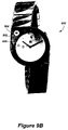
FIG. 3B depicts a watch device according to another embodiment of the invention;
FIG. 4A is a diagram illustrating a watch device and related components;
FIG. 4B is a functional block diagram of a watch device according to an embodiment of the invention;
FIGS. 5A and 5B depict a watch device according to another embodiment of the invention;
FIG. 6 depicts a watch device according to another embodiment of the invention;
FIGS. 7A and 7B depict a watch device according to yet another embodiment of the invention;
FIG. 8 depicts a watch device according to an embodiment of the invention;
FIGS. 9A and 9B depict a watch device according to another embodiment of the invention;
FIG. 10 depicts a watch device according to an embodiment of the invention; and,
FIG. 11 illustrates various alternative embodiments of the invention.
DETAILED DESCRIPTION OF THE PREFERRED EMBODIMENT
The present invention is described in the context of a wireless communication device for receiving and displaying information. In the described embodiments, the devices may be watch type devices that are specially configured to receive communication signals, as is described in greater detail below. As will become apparent from a reading of the following detailed description, the devices display information using mechanical elements or mechanical elements coupled with digital indicators, based at least in part upon received wireless signals transmitted from a source. Minor deviations from the described embodiments will also become apparent without departing from the spirit of the invention.
Although described here in the context of a watch-based system, it will be apparent that the teachings of the application have equal applicability to any other mobile or non-mobile devices, such as portable and desktop computers, personal digital assistants (PDAs), cellular telephones, clocks, etc. The use of a watch is for illustrative purposes only to simplify the following discussion, and may be used interchangeably with “mobile device.”
“Computer readable media” can be any available media that can be accessed by client/server devices. By way of example, and not limitation, computer readable media may comprise computer storage media and communication media. Computer storage media includes volatile and nonvolatile, removable and non-removable media implemented in any method or technology for storage of information such as computer readable instructions, data structures, program modules or other data. Computer storage media includes, but is not limited to, RAM, ROM, EEPROM, flash memory or other memory technology, CD-ROM, digital versatile disks (DVD) or other optical storage, magnetic cassettes, magnetic tape, magnetic disk storage or other magnetic storage devices, or any other medium which can be used to store the desired information and which can be accessed by client/server devices.
Communication media typically embodies computer readable instructions, data structures, program modules or other data in a modulated data signal such as a carrier wave or other transport mechanism and includes any information delivery media. The term “modulated data signal” means a signal that has one or more of its characteristics set or changed in such a manner as to encode information in the signal. By way of example, and not limitation, communication media includes wired media such as a wired network or direct-wired connection, and wireless media such as acoustic, RF, infrared and other wireless media. Combinations of any of the above are included within the scope of computer readable media.
The term “content” can be any information that may be stored in an electronic device. By way of example, and not limitation, content may comprise graphical information, textual information, and any combination of graphical and textual information. Content may be displayable information or auditory information. Auditory information may comprise a single sound or a stream of sounds.
The overall operating environment for the present invention will be discussed as follows below with reference to FIGS. 1-2.
Operating Environment
FIG. 1 illustrates an example operating environment 100 for the present invention. As illustrated in the figure, an FM signal or broadcast is transmitted over a communication channel 110 to various electronic devices. Example electronic devices that have an FM receiver or transceiver may include a desktop computer, a watch, a portable computer, a wireless cellular telephone (cell phone), and/or a personal data assistant (PDA). The electronic devices are arranged to receive information from the FM broadcast. The FM broadcast may be of any number of types including but not limited to: a standard FM transmission, a sub-carrier FM transmission, or any other type of FM transmission as may be desired.
Example electronic devices that may include an electronic system that is arranged to operate according to the interaction model are illustrated in FIG. 1. The electronic system may employ a wireless interface such as the FM transmission systems that are described above. Each of the electronic systems receives messages/information over the communication channel.
Each broadcast transmission corresponds to the transmission of one or more frames. Each frame may include multiple messages, where some messages are public broadcast (aka “global” or “shared” messages), while other messages are client specific messages (aka “personal” or “private” messages). Every client that is located within the designated service region may receive shared messages, while a single client may decode a private message.
Electronic devices (e.g., a wireless watch device) receive message packets according to shared and private messages that are directed to the client device. Message packets are organized in groups according to logical slot (or channel) entry numbers. For example, a particular electronic device is configured to receive a selected group of channels from the available channels. The message packets associated with each of those channels is received, processed, and stored in the client device. The stored message packets can be reviewed using a user interface that employs an interaction model, in accordance with the present invention.
Example channels include: a time channel, a messages channel, a contact channel, a calendar channel, a weather channel, a stocks channel, a news channel, sports, and/or a games channel. Messages associated with each channel include message content that is based on the particulars of the channel. For example, the weather channel may include the current weather in a local region, the current weather in a national region, and the current weather in an international region.
The operating environment shown and described provides examples of suitable operating environments and are not intended to suggest any limitation as to the scope of use or functionality of the invention. Other well known computing systems, environments, and/or configurations that may be suitable for use with the invention include, but are not limited to, personal computers, server computers, hand-held or laptop devices, multiprocessor systems, microprocessor-based systems, programmable consumer electronics, network PCs, minicomputers, mainframe computers, distributed computing environments that include any of the above systems or devices, and the like.
Illustrative Electronic System
FIG. 2 is a schematic diagram illustrating functional components of an illustrative electronic device 200. The electronic device 200 has a processor 260, a memory 262, a display 228, and a user interface 232. The memory 262 generally includes both volatile memory (e.g., RAM) and non-volatile memory (e.g., ROM, Flash Memory, or the like). The electronic device 200 includes an operating system 264, such as the Windows CE operating system from Microsoft Corporation or another operating system, which is resident in the memory 262 and executes on the processor 260. The user interface 232 may be a series of push buttons, a scroll wheel, a numeric dialing pad (such as on a typical telephone), or another type of user interface means. The display 228 may be a liquid crystal display, a multiple bit display, a mechanical display, a hybrid display, or a full color display or any other type of display commonly used in electronic devices. In one example, the display 228 may be touch-sensitive that would act as an input device.
One or more application programs 266 are loaded into memory 262 and run on the operating system 264. Examples of application programs include phone dialer programs, email programs, scheduling/calendaring programs, PIM (personal information management) programs, Internet browser programs, and so forth. The electronic device 200 also includes a non-volatile storage 268 that is located within the memory 262. The non-volatile storage 268 may be used to store persistent information which should not be lost if the electronic device 200 is powered down. The applications 266 may use and store information in the storage 268, such as e-mail or other messages used by an e-mail application, contact information used by a PIM, appointment information used by a scheduling program, documents used by a word processing application, and the like.
The electronic device 200 has a power supply 270, which may be implemented as one or more batteries. The power supply 270 might further include an external power source, such as an AC adapter or a powered docking cradle that supplements or recharges the batteries.
The electronic device 200 is also shown with various types of external notification mechanisms: one or more light-emitting diodes (LEDs) 240, an audio interface 274, a tactile interface 276, and one or more mechanical elements 278 included as part of the display 228. These devices may be directly coupled to the power supply 270 so that when activated, they remain on for a duration dictated by the notification mechanism even though the processor 260 and other components might shut down to conserve battery power. The LEDs 240 may be programmed to remain on indefinitely until the user takes action to indicate the powered-on status of the device. The audio interface 274 is used to provide audible signals to and receive audible signals from the user. For example, the audio interface 274 may be coupled to a speaker for providing audible output and to a microphone for receiving audible input, such as to facilitate a telephone conversation, or as a user interface using voice recognition. In another example, as described further below, a vibration device (tactile interface 276) can be used to give feedback to the user such as for alerting the user of a newly arrived message and/or other information. The electronic device 200 may control each alert mechanism separately (e.g., audio, vibration, as well as visual cues).
The electronic device 200 also includes a radio interface layer 272 that performs the function of receiving and/or transmitting radio frequency communications. The radio interface layer 272 facilitates wireless connectivity between the electronic device 200 and the outside world, via a communications carrier or service provider. Transmissions to and from the radio interface layer 272 are conducted under control of the operating system 264. In other words, communications received by the radio interface layer 272 may be disseminated to application programs 266 via the operating system 264, and vice versa (described below).
In one example of the present invention, electronic device 200 is a mobile electronic device such as a watch device that includes a wireless interface. Exemplary user interfaces for a watch device are shown in FIGS. 3A and 3B, as will be described below. Although the below-described user interface configurations include multiple selector buttons (e.g., four selector buttons), the functions of many of the selector buttons may be combined by a single selector (e.g., a button, a rocket switch, a wheel, etc.).
User Interfaces (UI)
FIG. 3A illustrates an exemplary watch device 300 that includes a user interface to an electronic system that is configured to operate in accordance with the present invention. The watch device 300 includes a bezel 302, which has an electronic system (e.g., see FIG. 2 and FIG. 4 below). The bezel 302 has an analog and/or digital display 304. The bezel includes analog-type watch hands 306 a-c for tracking hours, minutes, and seconds. In alternative embodiments, the watch hands may be used to track or draw attention to other information.
The watch device 300 includes a series of selectors 308 a-c that are arranged to operate as a user interface (UI). Selector 308 c operates according to both translational and rotational movement, allowing multiple functions to be performed, as described further below. Each selector may be implemented to have default function, and/or a context determined function. The currently selected channel determines the context for each selector. The electronic watch device 300 is context sensitive in that the function that is associated with each selector may change based on the selected channel or display screen.
A first one of the selectors 308 a may control a first analog and/or digital display 310. In FIG. 3A, the display 310 is an analog display. As used herein, “analog display” refers to indicating information using mechanical indicators. The analog display of FIG. 3A includes a gradated area having a plurality of “tick” marks, including “positive” and “negative” indicators. Each tick mark may be used to indicate a greater or lesser quantity, status, or amount. The analog display further includes a pointer 312 for pointing to a tick mark, based on the wireless information received and processed by the device 300. In a similar fashion, a second one for the selectors 308 b may control a second analog and/or digital display 314. For this example, display 314 is a digital display, depicting a stock indicator as the selected current channel. As will be described below, the device 300 includes a variety of current channel indicators which can be displayed on the digital display 314. FIG. 3A depicts that a stock channel is the current channel, wherein no change has occurred heretofore based on the “zero” indication of the analog display 310. A positive change in the stock channel, such as NASDAQ for example, is indicated when the pointer 312 is pointing to the positive side of the analog display. A negative change in the stock channel, is indicated when the pointer 312 is pointing to the negative side of the analog display.
As one example, activation of selector 308 a can reset the display to a default setting. Alternatively, activating selector 308 a may page up from a current displayed event/category to a previous event/category. The resetting of the display 310 may be accomplished by activating the first selector for a predetermined time period. For example, when the selector is a button as shown in FIG. 3A, the button is held for a timeout interval such as two seconds before the setting function is activated. Alternatively, activating selector 308 b may page down from a current displayed event/category to a next event/category. A backlighting function may be utilized when both selectors 308 a-b are simultaneously depressed for a predetermined interval.
For the embodiment shown in FIG. 3A, a third one of the selectors 308 c is to control various aspects of the device including controlling the analog hands 306 a-c. The third selector may be retracted from the bezel to a plurality of positions. At each position, the third selector may be rotated clockwise or counter-clockwise to control certain functions. One of the third selector positional states may also operate to control one or more analog/digital displays. That is, the third selector may be configured as a “master” selector, operable to control all functional aspects of the watch device 300. The third selector 308 c may also have an alternate function based on the currently selected channel (a stock channel, for example) or display. In one example, the third selector is activated by retracting the selector to a first position with respect to the bezel and rotating the selector in a clockwise manner for a predetermined time interval (e.g., two seconds) to select a main channel or “primary” channel (a stock channel, for this example). The selectors are arranged such that the electronic device accomplishes navigating and selecting content on a channel in a simple manner.
Selectors 308 a-c may also be replaced with a wheel type of device. The functions of the selectors may be activated by rotating the wheel device in a counterclockwise and/or clockwise manner and/or by pressing the wheel device towards the watch bezel. It will be appreciated that other examples of selector mechanisms may be employed and the present invention is not intended to be limited to any specific examples/embodiments described herein.
Displaying Wireless Data
According to the present invention, a device is provided for receiving and processing a wireless signal, preferably a radio signal, transmitted by a source. The device is operable to display various information extracted from the wireless signal. The device is operable to receive “real-time” information, such as stock, sports, weather, and other information and to display the information using, in part or solely, analog (mechanical) indicator mechanisms. The invention provides a solution for consumers who are unwilling to use or wear wireless electronic devices due to inelegant or undesirable display characteristics of the devices. For example, certain watch consumers will not wear watches that do not have certain user-oriented characteristics, such as quartz displays, chronograph features, perpetual calendars, kinetic winding, etc. Other users are dissatisfied with the rather inelegant digital displays associated with many electronic watch and other products. The present invention provides solutions to these and other problems associated with consumer satisfaction and preference. However, it will be appreciated that the present invention is not limited to watch devices, and those skilled in the art will realize the benefits of the present invention for other mobile electronic devices.
In addition to the watch devices described above, yet another exemplary watch device 400 is shown in FIG. 4A. The watch device 400 includes an electronic system 402 that is configured to operate in accordance with the present invention. The watch device 400 includes a watchband 404 that includes an antenna that is either attached to the watchband or integrally formed within the watchband 404. The antenna is coupled to the electronic system 402 contained in the watch. The electronic system 402 may be contained in the bezel as shown in FIG. 4A, or in some other portion of the watch device.
The electronic system 402 is a computer-based system, including functionality of operating as either a receiver and/or transceiver type of device. As illustrated in the figure, the electronic system includes a transceiver 406, a microcomputer unit or microprocessor 408, and an analog radio 410. The antenna connects to, and is controlled by, the transceiver 406. Transactions between the microprocessor 408 and the radio components are mediated over a microprocessor-digital transceiver interface. The components of the watch device 400 are housed in a watch-sized enclosure and rely on battery power for operation.
The transceiver 406 generally includes a digital signal processor (DSP) 412, which performs control, scheduling, and post-processing tasks for the transceiver, and a real-time device (RTD) 414, which includes a digital radio, system timing, and real-time event dispatching. The DSP 412 is coupled to the microprocessor 408, and transceiver tasks are commanded by the microprocessor 408.
One of the DSP's tasks may process received data for such purposes as sub-carrier phase recovery, baud recovery and/or tracking, compensation for fading effects, demodulation, de-interleaving, channel state estimation and error-correction. The post-processing of packets may occur when an entire packet has been received, or another subsequent time. The DSP 412 analyzes the transmitted data packets to determine a broadcast station's signal timing with respect to a local clock of the RTD 414. The local clock is synchronized with the transmitter's clock signal to maintain signal sampling integrity. The receiver is periodically brought into symbol synchronization with the transmitter to minimize misreading of the received data.
The digital section of the RTD 414 may include system time-base generators, such as a crystal oscillator that provides a system clock for the microprocessor 408 and the DSP 412. The time-base also provides baud and sample timing for transmit and receive operations, start/stop control for radio operation, and controls the periods of clock suspension, when required. The RTD 414 also performs radio operations, and may perform additional operations as well. The radio 410 is arranged to receive segments of data that is arranged in packets.
As described above, the user interface is configured as a means for selecting one or more services. In one example, a wireless client device user interacts with the user interface to select services such as news, stock prices, weather, and other features such as a personal calendar, address book, and the like. Selected services are entered in a database for broadcast transmission at a later time. At the designated time (or time interval) the scheduling interface communicates with the broadcast server to begin a transmission sequence of data for the selected services. The broadcast server subsequently formats the data for reception by one or more wireless client device, queues the data for transmission, and communicates the queued data to the FM broadcast tower for transmission. In an alternative example, the scheduling interface communicates the selected services to the broadcast server. The broadcast server schedules the time interval for transmission of the selected service.
Each broadcast transmission corresponds to the transmission of one or more frames that are arranged in accordance with a frame protocol. Each frame may include multiple messages, where some messages are public broadcast (aka “global” or “shared” messages), while other messages are client specific messages (aka “personal” or “private” messages). Each frame includes a table of contents that indicates the extent of messages that are found within the next transmitted frame. Every client that is located within the designated service region may receive shared messages, while a single client may decode a private message.
Each frame includes a header, a table of contents, and a message payload that includes the content for one or more selected services as previously described. The header also includes other information such as authentication data, identified service region, language, available stations for the identified service region, frame number, and time stamp. Control information may also be included in one of the headers to indicate broadcast conditions such as a change in available channels, an assignment of a service region to a particular wireless client device, and an assignment of a particular channel (frequency). In one example, each frame includes a change counter in one of the headers to indicate a change has taken place in the system. Wireless client devices (clients) may use the change counter to determine when to initiate a failover (when a broadcast tower becomes unavailable).
Client devices may be organized in a series of layers that are similar to the OSI networking model. The layers include a physical layer, a link layer, a network layer, a transport layer, and an application layer. The physical layer receives the FM subcarrier transmitted information and provides symbols to the link layer. The link layer divides the symbols into segments, and handles viterbi coding, data whitening, and interleaving functions. The network layer receives the segments and creates logical packets. The network layer also handles cyclic redundancy check (CRC), encryption, and Reed-Solomon coding. The transport layer decodes the logical packets to retrieve a table of contents (TOC), and includes data handlers that handle communication to the application layer. The application layer includes a series of applications that are resident on the client device, and associated with subscriptions to broadcast services.
Applications on the client device are registered with the transport layer. The transport layer maintains the data handlers for each registered application, and retrieves the TOC from the logical packets that are received from the network layer. The transport layer notifies the registered applications that data streams will be available in the next frame transmission as identified with the service ID. Each application program applies a series of metrics to determine priority for the receipt of data streams, which are submitted to the transport layer in the client device. Prioritization is performed independently by each application on the client device based on any criteria such as preferred data, error correction requirements, as well as base and elevated priority levels. The transport layer reviews all of the requests, decides which requests will be accepted, and translates the accepted requests into packet requests to the network layer. The network layer retrieves the relevant packets in the next frame transmission and passes the packets to the relevant registered applications via the data handlers.
Referring to FIG. 4B, a functional block diagram of a wireless client device 420 is shown. As described herein, the client devices offer a flexible and customizable programming environment, based on .NET Framework standard languages, mainly C#, for example. The devices execute intermediate language (IL) produced by the existing and commercially available .NET compilers. Applications may use and extend the various libraries; a Shell Library 422 and a Hardware library 424, for example. The Shell library 422 and Hardware 424 library collaborate to format information received not only from a user's input, but also received wireless signals. The device presents the formatted information to the user leveraging various mechanical and/or electrical mechanisms, described below.
The lowest layer in the architecture is the Mechanical/Electrical layer 426 and operates to, among other things, gather raw input from the wireless signals, here the received FM transmission and/or the user. This layer 426 also operates to present a user with formatted information in response to raw input and/or the user interaction itself. To enable operation in this software driven environment, the mechanical or analog display outputs require a mechanical to electrical built in conversion whose result is going to be handled by a Hardware Abstraction Layer (HAL) 428. The HAL layer 428 serves as an interface layer between raw electrical signals and bit encoded information. The HAL layer 428 offers generalization over underlying hardware, so that different hardware components that present similar characteristics can be treated in a homogeneous way by the Common Language runtime (CLR) layer 430.
With continuing reference to FIG. 4B, the CLR layer 430, manages the execution of the application and provides all the services and type system implementation for executing standard IL language. For this embodiment, the CLR and HAL layers 430 and 428, respectively, interact to provide an operating system (OS) environment for application programming and execution. The CLR layer 430 convoys and consolidates hardware events to and from the HAL layer 428 and exposes them for consumption to the libraries layer 432, as well as gathering various events from library layers calls.
According to this embodiment, libraries are implemented in high NET framework languages and are compiled into IL code. Libraries are object oriented APIs and are the only layer exposed to application programmers, offering a safe execution environment. The device 420 utilizes a number of libraries including Hardware libraries and managed driver libraries offering an object oriented API capable of driving the underlying hardware while listening and reacting to the hardware events, such as a button press or a wireless signal capture event. According to other embodiments, the libraries and drivers may be extended to fit to various H/W characteristics.
As described above, each client device includes a processor having an ARM 7 (or 9) core with additional functionalities such as: general purpose I/O (GpIO), VTU (Versatile Timer Unit); SPI and others features meant to drive and communicate with hardware; VTU exposes distinct Pulse Width Modulation (PWM) functionalities as well as input capture functionalities. The external hardware, including the various analog (mechanical) indicators described herein, is abstracted into a set of objects in the Shell 422 and H/W 424 libraries. Those objects expose the feature of interest of the H/W to the managed application and leverage the processor capabilities to communicate and drive the hardware. The hardware and the application preferably provide 2 way interaction: the application can collect data from the H/W by mean of both push and pull mechanisms and can force H/W to enter a particular state, therefore driving it. Thus, the communication to and from the hardware layer 432 and the application layer 434 is bidirectional built on top of the API object model.
As described above, Application inputs though the H/W may consist of user input and wireless signal data received over the wireless signal channel, radio for example, or through a connection (COM or USB) to a host PC or again through direct user input. The output of the application consist of elaborated data directed to an application running on the host PC or to the electrical and/or mechanical media designed to present the user with the information.
The object API and its interaction with the CLR and the underlying HAL layer allow the application programmer to express the information with a very wide variety of mechanisms. The presentation layer may use visual, tactile and acoustic mechanisms which may be electrical or mechanical, LED and LCD displays, hands, dials, rings, disks and in general any motion or motionless mechanism that can be driven out of an electrical modulated source and produce a tactile, visible, and/or acoustic feedback. Those skilled in the art will appreciate the various mechanisms useful for conveying information to a user and the invention is not intended to be limited by any examples or illustrations described herein.
The mechanisms are programmable by controlling the production and modulation of an electrical signal from the object API layer. For example, one implementation uses general API capable of driving the GpIO and VTU circuits of the core or by using more sophisticated and peculiar drivers that may use those underlying APIs or call directly into special purpose routines in the CLR and HAL layers. The libraries are designed to allow both push and pull programming paradigm: the CLR layer can call back into the libraries in response to a H/W event or libraries can poll the CLR layer 430 which in turn polls the HAL layer 428 to extract the H/W state and act upon a change.
Referring again to FIG. 3A, a watch device 300 is shown displaying information received from a wireless signal, a signal broadcast over a FM channel, for example. The watch device 300 is preferable to many consumers due to the refined and traditionally elegant appearance. The watch device 300 may include a combined analog and/or mechanical display for displaying a category or context and/or a value indication. For this example, a user of the watch has set the watch to a stock information channel using one of the selectors 308 described above. Optionally, the stock information channel may be included as a default channel based on user preference.
As described above, the watch device 300 includes analog or mechanical display features 310 and/or a digital display 314 for displaying information received from wireless signals transmitted from a radio-frequency (RF) driven source, preferably a frequency modulated source. The information contained in the wireless signals may include stock information, sports information, weather information, and other desired user information. The inventive watch device allows information received from wireless signals to be conveyed to a user using the analog and/or mechanical display features, described in detail below.
As depicted in FIG. 3A, a watch device 300 includes an analog display 310 for conveying information received from a wireless signal. For this example, information is also conveyed via the digital display 314. In conjunction, the two displays 310 and 314 convey information to a user based upon a currently selected channel. The user, using the user interface, may select the current channel for display. The user may also select an update rate for updating the display. The device 300 includes timing mechanisms for receiving wireless signals and disseminating information from the signals. The timing mechanisms may be adjusted according to user preference.
In alternative embodiments, channels may be automatically displayed as part of a rotating schedule. For example, the analog and digital displays 310 and 314 may update and convey stock information based a stock channel transmission for a predetermined time period. It is also possible to independently update each display. After the predetermined time period, two minutes for example, the analog and digital displays 310 and 314 may convey sports-related information based a sport channel transmission for a predetermined time period, which may be a different period as compared to other display periods. The timing and update features are applicable to the embodiments discussed below.
According to the example depicted in FIG. 3A, the watch device 300 is currently receiving wireless broadcast transmissions from a stock channel. An informational icon 316, a stock channel indicator for this particular example, alerts the user of the watch device 300 that the current channel is the stock channel. That is, a stock information icon 316 is displayed in the digital display 314, providing context to the user of the device 300. The stock information icon may also be displayed using an analog display, described further below. In conjunction, the two displays 310 and 314 convey information to a user based upon a currently depicted stock channel. The digital display 314 is informing the user that the watch device is currently receiving information from a stock channel.
The analog display 310 includes a pointer 312 and “plus” and “minus” indicators 313 a and 313 b. The “plus” and “minus” indicators correspond to positive and negative changes in the stock index according to the current channel displayed in the digital display 314. In another example, the “plus” and “minus” indicators may correspond to positive and negative changes relative to a contender in a sporting contest, such as a football game. A positive indication conveys to the user that the particular stock, team, etc. is up based on the current display.
The pointer 312 conveying the relative information is controlled in part by the information received from the wireless broadcast signals. As discussed above, after processing the wireless signals, the electronic system converts the information to control inputs for controlling the movement of the pointer 312. The electronic system also converts the information to control the output of the digital display 314. The gradated analog display alerts the user as to whether a major change, no change, or a minor change has occurred with respect to the currently displayed channel. The further the pointer 312 extends into the “plus” or “minus” sectors, the greater the change. As shown in FIG. 3, the pointer 312 of the analog display 310 conveys to the user that the particular stock channel shown in the digital display 314 (a NASDAQ channel for example) is unchanged at the moment. It will be appreciated that the watch device 300 may include other informational icons in the digital and/or analog displays as well and is not limited to any specific type of informational content.
For example, the watch device 300 may receive a transmitted message including a stock quote from a stock channel broadcast service. The broadcast service for the stock channel may have a series of subscribed stock quotes (e.g., MSFT, IBM, ORCL, etc.) that are indexed for an application on the client device. For this type of data stream, the stream locator identifies the starting location for the stock quote messages on the stock channel application for the client device. Each subsequent stock quote is a separate message that follows in sequence after the starting location identified by the stream locator. The client gathers all of the packets of the message before deserializing the content for the application layer.
Referring now to FIG. 3B, another watch device 330 is shown displaying information received from a wireless signal, a signal broadcast over a FM channel, for example. For this example, a user of the watch has set the watch to a stock information channel, NASDAQ, using one or more of a plurality selectors 332 a-c similar to those described above in conjunction with FIG. 3A. However, selector 332 b is a push-button type selector. As described above, the watch device 330 includes analog or mechanical display features 334 and/or a digital display 336 for displaying information received from wireless signals transmitted from a radio-frequency (RF) driven source, preferably a frequency modulated source. The information contained in the wireless signals may include stock information, sports information, weather information, and other desired user information, as described below.
As depicted in FIG. 3B, the watch device 330 includes an analog display 334 for conveying information received from a wireless signal. For this example, information is also conveyed via the digital display 336. In conjunction, the two displays 334 and 336 convey information to a user based upon a currently selected channel. The user, using the user interface, may select the current channel for display, as described above. The watch device 330 is currently receiving wireless broadcast transmissions from a NASDAQ stock channel. That is, the digital display 336, using a NASDAQ indicator 338 for this particular example, alerts the user of the watch device 330 that the current channel is a NASDAQ stock channel. The NASDAQ indicator may also be displayed using an analog display, described further below. In conjunction, the two displays 334 and 336 convey information to a user based upon a currently depicted stock channel.
The analog display 334 includes a pointer 340 and “plus” and “minus” indicators 340 a and 340 b. The “plus” and “minus” indicators correspond to positive and negative changes in the stock index according to the current channel displayed in the digital display 336. In another example, the “plus” and “minus” indicators may correspond to positive and negative changes relative to a contender in a sporting contest or to temperature changes, etc. The “plus” and “minus” indicators may also correspond to the potential for bad/good weather or financial conditions.
The pointer 340 conveying the relative information is controlled in part by the information received from the wireless broadcast signals. After processing the wireless signals, the electronic system converts the information to control inputs for controlling the movement of the pointer 340. The electronic system also converts the information to control the output of the digital display 336. The gradated analog display alerts the user as to whether a drastic change, no change, or a minor change has occurred with respect to the currently displayed channel, as described above. As shown in FIG. 3B, the pointer 340 of the analog display 334 conveys to the user that the NASDAQ stock channel is unchanged at the moment, based on the information received and processed by the watch device.
According to the examples depicted in FIGS. 3A and 3B, a small LCD or equivalent digital display may be used to display the category or context of information such as Nasdaq (stocks), barometer (weather), Yankees (sports), portfolio (investments), or appointment. Selectors on the side of the watch, or an equivalent button-functional interface is used to switch between various categories and/or contexts. An extra hand or similar analog device on the watch may be separately controlled to show the value based on the currently selected context. For some contexts, like Appointment, the pointer may be used to point to actual hour locations on the dial indicating the time of the next appointment (rather than using the +/− scale); the digital display could show the location or subject. Other types of information could use the 0-10 scale to show decimal values and fractions of values. A custom scale could also be printed using the whole dial—an example would be to print icons at hour locations such as cloudy, overcast, sunny, rainy, etc for weather. As an alternative the extra hand could be omitted and the existing hands could simply function as a temporary pointer when a new category is selected.
Referring now to FIGS. 5A and 5B, yet another exemplary watch device 500 is shown. The watch device 500 is displaying the current time and other information received from a wireless signal, a signal broadcast over a FM channel, for example. The watch device 500 is tuned to receive and disseminate transmissions from the FM transmitter. As shown in the FIGURES, the watch device 500 has a refined and elegant appearance, which is preferable for many consumers.
The watch device 500 includes a bezel 502, which preferably contains an electronic system. The bezel 502 includes a plurality of analog displays 504 and 506. The bezel also includes analog-type watch hands 508 a-c for tracking hours, minutes, and seconds. In alternative embodiments, the watch hands may be used to track or draw attention to other information. For this embodiment, it is preferred that the hour and minute hands 508 a and 508 b also each include a light-emitting diode (LED) 510 a and 510 b, respectively. Each hour mark 512 also preferably includes an LED. The watch device 500 utilizes the LEDs, alone or in combination to convey information to a user of the device, as described further below. The watch device 500 also includes at least one selector 514 operable as a user interface (UI). The selector 514 operates according to both translational and rotational movement, allowing multiple functions to be performed based on how the selector is manipulated by the user (see the description with respect to FIG. 3 above).
As shown in FIG. 5A, first and second analog displays 504 and 506 are displaying information received from a stock channel. According to one embodiment, a user may set the watch to receive information from a stock information channel using the selector 514 described above. Optionally, the wireless signals may, in part, control what information the watch displays, based on the information contained in the wireless signals. According to this embodiment, the watch device 500 utilizes two analog displays and/or at least one LED to display information received from wireless signals transmitted from a radio-frequency (RF) driven source, preferably a frequency modulated source.
The first and second analog displays 504 and 506, in conjunction, convey information to a user based upon a currently selected channel. For this embodiment, the analog displays 504 and 506, each include a window fabricated as part of the watch face and an information indicator mechanism including a plurality of informational icons, described below. The first analog display includes window 504 a and information indicator mechanism 504 b. As depicted in FIG. 5A, the watch device is currently receiving wireless broadcast transmissions from a DOW Jones index stock channel. An informational icon 516 of the first analog display, a DOW stock channel indicator for this particular example, alerts the user of the watch device 500 that the watch device is utilizing DOW stock information from the wireless signals. The user knows that the watch is utilizing DOW stock information based on the DOW information icon being displayed in the window of the first analog display 504.
The second analog display 506 also includes a window 506 a and an informational indicator mechanism 506 b including a plurality of informational icons. An informational icon 518 of the second analog display provides additional information to the user based on the icon displayed in the first analog display 504. For example, the second analog display 506 is currently displaying an informational icon having an upwardly pointing arrowhead or right-side-up triangle, thereby providing a relative value. The informational icon 518 alerts the user of the watch device 500 that DOW stock index is up for the day or positive, based on the symbols displayed by the first and second analog displays.
With additional reference now to FIG. 5B, the first and second analog displays 504 and 506 are shown in greater detail. The first analog display includes an information indicator mechanism 504 b. The information indicator mechanism 504 b includes a plurality of informational icons 516 a-g. In similar fashion, the second analog display includes an information indicator mechanism 506 b. The information indicator mechanism 506 b also includes a plurality of informational icons 518 a-j. When displayed, each informational icon conveys a distinct type of information to a user of the watch device 500. In conjunction, informational icons 516 a-g and 518 a-j provide information to a user based on wireless signals received and processed by the watch device 500. More particularly, informational icons 518 a-j may be described as providing relative and/or specific information with respect to informational icons 516 a-g.
For example, as shown in FIGS. 5A and 5B, the watch device 500 is displaying a DOW informational icon 516 a in the first analog display 504. The positive arrow indicator 518 a of the second analog display 506, informs the user that the DOW is up at the present time based on the information received and processed from the wireless signals. When displayed, the negative arrow indicator 518 b of the second analog display 506 conveys to the user that the DOW is down at the present time. Continuing, when displayed, the no-change indicator 518 c of the second analog display 506, conveys to the user that the DOW has not changed.
The first analog display 504 also includes other stock indicator icons 516 c-d and 516 f-g which are associated with different stock information. Stock indicator icon 516 b corresponds to the New York stock exchange (NYEX), stock indicator icon 516 c corresponds to the American stock exchange (AMEX), stock indicator icon 516 f corresponds to the NASDAQ stock exchange (NASD), and stock indicator icon 516 g corresponds to the Standard & Poor's (S&P). As described above, informational icons 518 a-c may be used in conjunction with informational icons 516 a-c and 516 f-g to convey relative and/or specific stock information to a user of the watch device 500.
With continuing reference to FIG. 5B, the first analog display 504 also includes a barometer icon (BARM) 516 d and a weather icon (WTHR) 516 e. Informational icons 518 a-c of the second analog display may also be used in conjunction with both the barometer and weather icons to convey rising, unchanging, or decreasing pressures and temperatures. The second analog display 506 further includes weather indicator icons 518 d-j, used in conjunction with the weather icon 516 e to convey specific weather information to a user of the watch device 500. When displayed, each weather indicator icon conveys information, that is: weather indicator icon 518 d informs the user of snow or ice or a chance of snow or ice; weather indicator icon 518 e informs the user of a thunderstorm or a chance of a thunderstorm; weather indicator icon 518 f informs the user of rain or a chance of a rain; weather indicator icon 518 g informs the user of clouds with some rain; weather indicator icon 518 h informs the user of partly cloudy forecast; weather indicator icon 518 i informs the user of partly sunny forecast; and, weather indicator icon 518 j informs the user of a sunny forecast. It should be noted that the device may provide weather information to a user based on the user's current location or some predetermined location.
For this embodiment, each information indicator mechanism may be in the form of a disk or wheel located behind the watch face 520, so that the user only sees an icon displayed through the windows 504 a and 506 a. It will be appreciated that other mechanisms may be utilized for the information indicator mechanism 504 b, such as a rotating drum, rotating tape, etc. Whatever mechanism is used for the information indicator mechanism, it should be designed to be pleasing to the eye, i.e. elegant. The information indicator mechanism 504 b, a disk for this embodiment, may be driven by a motor, piezoelectric devices, and the like, based on wireless signals received and processed by the electronic system. Each disk may be rotated to display a particular icon based upon the information processed from the wireless signals by the electronic system.
Referring now to FIG. 6, yet another exemplary watch device 600 is depicted. Watch device 600 includes an analog display 602 similar to the analog display described above in conjunction with FIGS. 5A and 5B. The analog display 602 is informing the user that the weather is currently partly sunny. The watch device 600 also includes a gradated display 604 having “plus” and “minus” indicators 606 and 608, which provide relative indications of the information displayed in the analog display 602. An indicator 610 is operable to rotate around the gradated display, informing the user of the intensity, severity, gain, loss, likelihood, etc. of the informational icon 603 displayed in the analog display 602. The more positive the position of the indicator 610, the greater the intensity, severity, gain, probability likelihood, etc. The more negative the position of the indicator 610, indicates greater loss, less intense, severe, or probability likelihood according to the informational icon 603 displayed in the analog display 602. The indicator 610 may be implemented as a series of LEDs located around the circumference of the bezel, a mechanical or analog rotational device, or a digital display, such as an LCD, controlled based on the information received from the wireless signal transmission.
According to the invention, a watch device may be tailored to a particular consumer's requirements, a particular sports team, for example. Referring to FIGS. 7A and 7B, another exemplary watch device 700 is shown. The watch device 700 is tailored to satisfy certain requirements of a sports fan, a New York Yankee fan for this example. The watch device 700 includes a plurality of analog displays, four according to this embodiment, a first analog display 702, second analog display 704, third analog display 706, and fourth analog display 708.
According to this example, a user ordered the watch device 700 based on his/her zeal as a New York Yankee fan. Based on this, the watch device 700 is fabricated with the New York Yankee logo 703. The first analog display 702, informs the user of the current inning of a baseball game, the top of the third inning for this example. The second analog display 704 informs the user that the Yankees have 3 runs. Third analog display 706 informs the user that the Yankees are playing Boston, who currently have 1 run, according to fourth analog display 708. Based on information received from a wireless sports channel transmission, the analog displays inform the user of a favorite team's game status, for example.
As shown in FIG. 7B, the first analog display 702 includes first and second rotatable disks 702 a and 702 b. First disk 702 a informs a user of the current inning. Second disk 702 b, informs the user as to which team is at bat, i.e. top or bottom of the current inning. The second disk 702 b is also operable to display extra innings. The second analog display 704 includes first and second rotatable disks 704 a and 704 b. First disk 704 a informs a user of the current run amount in single digits. Second disk 704 b, when displayed, informs the user of current run amount in increments of ten. The third analog display 706 informs the user of the Yankee's current opponent, the Boston Red Sox, for this example. The fourth analog display 708 also includes first and second rotatable disks 708 a and 708 b. First disk 708 a informs a user of the current run amount in single digits. Second disk 708 b, when displayed, informs the user of current run amount in increments of ten.
It will be appreciated that the analog displays may be tailored to a variety of events, such as football, hockey, golf, etc. according to a user's preference. Optionally, the watch device 700 may be fabricated having a number of LED 710 a-f, for alerting the user to various events of a game, etc., in addition to the analog displays. Thus, a common module may be produced and re-used for similar applications, that is, for other teams, etc. For example, FIG. 8 depicts a watch device 800, having the same watch module, but tailored to meet the needs of a Chicago Cubs fan, i.e. a different color scheme, logos, etc.
FIGS. 9A and 9B depict a watch device 900 operable to display an “instant” icon or emoticon based on information received from wireless signal transmissions. The watch device 900 includes an analog display 902 for displaying information received from wireless signals by the watch device 900. The analog display 902 includes a plurality of informational icons 904 distributed on a rotatable disk 906. The watch device 900 is operable to display a heart, happy, sad, and other emoticons based on the information received and processed from the wireless signal transmission. The watch device 900 is also operable to inform the user to call home, check e-mail, etc. based on a currently displayed icon 904.
FIG. 10 depicts yet another exemplary watch device 1000. Watch device 1000 includes a plurality of analog displays 1002, 1004, and 1006. First analog display 1002 is similar to the analog display descried above in conjunction with FIGS. 5A and 5B. For some categories of data the data value can be expressed as an icon that conveys both value and context. For this example the cloud with drop icon infers rainy weather, a zig-zag upward arrow would indicate that the user's portfolio is up, etc. Second and third analog displays 1004 and 1006 are fabricated as rotatable perimeter disks having information icons 1008 and 1010 (sunrise and sunset, for this example) imprinted thereon. The second and third analog displays 1004 and 1006 operate to indicate times for sunrise and sunset. The watch device 1000 displays the times of sunrise and sunset according to the user's location or some other location. As shown in FIG. 10, sunrise takes place around 7am and sunset takes place around 6p.
In various alternative embodiments, one or more of the LEDs may be used to convey information to the user of the watch device. For example, the LEDs may be caused to display “red” when a particular stock index or team is down for the day, or if the weather is severe or threatening. The LEDs may be caused to display “green” when a particular stock index or team is up for the day, or if the weather is pleasant, for example. Vibration and/or sound output from the tactile interface 276 and/or audio interface 274 may also be used to convey information to a user of the watch device based on received and processed wireless signals. For example, the watch device may be caused to vibrate and/or emit a sound if the user's team wins a game or if a significant change has occurred in a stock portfolio. The vibration and/or sound may be modulated at different frequencies according to different events, for example a loss, win, stock up or down, extra innings or periods, etc. It will be appreciated that each information indicator mechanism may be fabricated to include greater or fewer informational icons operable to convey different types of content, and the invention is not intended to be limited by any examples and/or embodiments disclosed herein.
The present invention is not limited to a watch device. For example, the arrows in FIG. 11 point to locations in a vehicle where the present invention may be implemented. The invention may also be implemented in larger objects which would not look right without retaining their aesthetic qualities, like a grandfather or cuckoo clock, for example. The invention is equally applicable to these types of items and others. The information contained in the wireless signals may include stock information, sports information, weather information, and other desired user information. Furthermore, the invention is not limited to any specific type of information that a device may convey. For example, a device, such as a grandfather clock, could have a different chime count or tone, which may alert a person to take certain medication, etc.
The above specification, examples and data provide a complete description of the manufacture and use of the composition of the invention. Since many embodiments of the invention can be made without departing from the spirit and scope of the invention, the invention resides in the claims hereinafter appended.

Claims (15)

1. A wristwatch apparatus comprising:
a mechanical selector having a first mechanical display indicator, wherein the first mechanical display indicator includes a plurality of icons that mechanically indicate available public frequency modulated (FM) channels, wherein each of the available public FM channels includes a different message content, wherein mechanical selection of an icon that indicates an available public FM channel causes retrieval of message content received from the available public FM channels, wherein the retrieval of the message content includes message content from the selected available public FM channel indicated by the icon of the first mechanical indicator of the mechanical selector, wherein the retrieval of the message content from the selected available public FM channel indicated by the icon of the first mechanical indicator of the mechanical selector causes the generation of control signals, wherein the control signals are generated by accessing a managed hardware driver library within the wristwatch apparatus and generating the control signal according to an API of one of the hardware drivers in the managed hardware driver library, wherein the control signals cause the mechanical movement of a second mechanical display indicator to mechanically indicate information according to the message content from the selected available public FM channel indicated by the icon of the first mechanical indicator of the mechanical selector;
an FM receiver integrated in the wristband of the wristwatch apparatus for receiving FM signals from each of the available public FM channels, wherein each of the available public FM channels includes information associated with the different message content;
an electronic system for receiving the mechanical selection of the available public FM channel according to the first mechanical display indictor, processing the selection according to an API for a first mechanical display indicator hardware driver in the hardware driver library to cause retrieval of information in the FM signal related to the selection by the first mechanical display indictor, extracting the information from the received FM signal, accessing the hardware driver library within the wristwatch apparatus, and generating the control signal based on an API of a second mechanical display indicator hardware driver in the hardware driver library to cause the mechanical movement of the second mechanical display indicator according to the information extracted from the received FM signal; and
a display for mechanically displaying the information extracted by the electronic system, wherein the display includes the first mechanical display indicator and the second mechanical display indicator, wherein the first mechanical display indicator includes the icon that indicates the selected available public FM channel, wherein the second mechanical display indicator includes the information in the context of the icon that mechanically indicates the selected available public FM channel.
2. The wristwatch apparatus of claim 1 wherein the FM receiver further comprises operational functionality in a FM frequency range.
3. The wristwatch apparatus of claim 1, wherein the second mechanical display indicator further comprises at least one mechanical indicator consisting essentially of a tactile, audible, or visual mechanism.
4. The wristwatch apparatus of claim 1, wherein the FM signals comprise message packets having at least one frame, wherein each frame includes a header, a table of contents and a message payload associated with at least one member of a group comprising: a time service, a message service, a contact service, a calendar service, a weather service a stock service, a news service, a sports service, and a game service.
5. The wristwatch apparatus of claim 1, wherein the display further comprises a third display indicator, and a fourth display indicator, wherein the third display indicator provides a context and the fourth display indicator provides a value related to the context.
6. A wireless client device comprising:
a mechanical selector having a first mechanical display indicator, wherein the first mechanical display indicator includes a plurality of icons that mechanically indicate available public frequency modulated (FM) channels, wherein each of the available public FM channels includes a different message content, wherein mechanical selection of an icon that indicates an available public FM channel causes retrieval of message content received from the available public FM channels, wherein the retrieval of the message content includes message content from the selected available public FM channel indicated by the icon of the first mechanical indicator of the mechanical selector, wherein the retrieval of the message content from the selected available public FM channel indicated by the icon of the first mechanical indicator of the mechanical selector causes the generation of control signals, wherein the control signals are generated by accessing a managed hardware driver library within the wristwatch apparatus and generating the control signal according to an API of one of the hardware drivers in the managed hardware driver library, wherein the control signals cause the mechanical movement of a second mechanical display indicator to mechanically indicate information according to the message content from the selected available public FM channel indicated by the icon of the first mechanical indicator of the mechanical selector;
an FM receiver for receiving FM signals from each of the available public FM channels, wherein each of the available public FM channels includes information associated with the different message content;
a processor for receiving the mechanical selection of the available public FM channel according to the first mechanical display indictor, processing the selection according to an API for a first mechanical display indicator hardware driver in the hardware driver library to cause retrieval of information in the FM signal related to the selection by the first mechanical display indictor, extracting the information from the received FM signal, accessing the hardware driver library within the wristwatch apparatus, and generating the control signal based on an API of a second mechanical display indicator hardware driver in the hardware driver library to cause the mechanical movement of the second mechanical display indicator according to the information extracted from the received FM signal;
a display for mechanically displaying the information extracted by the processor, wherein the display includes the first mechanical display indicator and the second mechanical display indicator, wherein the first mechanical display indicator includes the icon that indicates the selected available public FM channel, wherein the second mechanical display indicator includes the information in the context of the icon that mechanically indicates the selected available public FM channel; and
a power supply for providing power to the wireless client device.
7. The wireless client device of claim 6 further comprising a smart watch device.
8. The wireless client device of claim 6, wherein the FM receiver is operable to receive FM signals from an FM source.
9. The wireless client device of claim 6, wherein at least one of the first and second mechanical display indicators comprise at least one disk having at least one iconic symbol for conveying the information extracted from the received FM signal.
10. The wireless client device of claim 6, wherein at least one of the first and second mechanical display indicators comprise at least one disk having at least one textual display for conveying the information extracted from the received FM signal.
11. The wireless client device of claim 6, wherein at least one of the first and second mechanical display indicators comprise a first disk having at least one iconic symbol and a second disk having at least one textual display, the first and second disks operating in conjunction to convey the information extracted from the received FM signal.
12. The wireless client device of claim 6, wherein at least one of the first and second mechanical display indicators comprise a first disk having at least one numeric symbol and a second disk having at least one textual display, the first and second disks operating in conjunction to convey the information extracted from the received FM signal.
13. The wireless client device of claim 6, wherein at least one of the first and second mechanical indicators comprise a gradated area and a pointing means for pointing to a portion of the gradated area and operating to convey the information extracted from the received FM signal.
14. The wireless client device of claim 6, wherein the display further comprises a digital display.
15. A system for conveying information comprising:
a frequency modulated (FM) signal transmitter for transmitting FM signals, wherein the FM signals include a message payload for an FM channel; and
a device for receiving the FM signals including:
a mechanical selector having a first mechanical display indicator, wherein the first mechanical display indicator includes a plurality of icons that mechanically indicate available public frequency modulated (FM) channels, wherein each of the available public FM channels includes a different message content, wherein mechanical selection of an icon that indicates an available public FM channel causes retrieval of message content received from the available public FM channels, wherein the retrieval of the message content includes message content from the selected available public FM channel indicated by the icon of the first mechanical indicator of the mechanical selector, wherein the retrieval of the message content from the selected available public FM channel indicated by the icon of the first mechanical indicator of the mechanical selector causes the generation of control signals, wherein the control signals are generated by accessing a managed hardware driver library within the wristwatch apparatus and generating the control signal according to an API of one of the hardware drivers in the managed hardware driver library, wherein the control signals cause the mechanical movement of a second mechanical display indicator to mechanically indicate information according to the message content from the selected available public FM channel indicated by the icon of the first mechanical indicator of the mechanical selector;
an FM receiver for receiving FM signals from each of the available public FM channels, wherein each of the available public FM channels includes information associated with the different message content;
a processor for receiving the mechanical selection of the available public FM channel according to the first mechanical display indictor, processing the selection according to an API for a first mechanical display indicator hardware driver in the hardware driver library to cause retrieval of information in the FM signal related to the selection by the first mechanical display indictor, extracting the information from the received FM signal, accessing the hardware driver library within the wristwatch apparatus, and generating the control signal based on an API of a second mechanical display indicator hardware driver in the hardware driver library to cause the mechanical movement of the second mechanical display indicator according to the information extracted from the received FM signal;
a display for mechanically displaying the information extracted by the processor, wherein the display includes the first mechanical display indicator and the second mechanical display indicator, wherein the first mechanical display indicator includes the icon that indicates the selected available public FM channel, wherein the second mechanical display indicator includes the information in the context of the icon that mechanically indicates the selected available public FM channel; and
a power supply for providing power to the system.
US10/941,374 2004-09-15 2004-09-15 Display of wireless data Expired - Fee Related US7593755B2 (en)

Priority Applications (5)

Application Number Priority Date Filing Date Title
US10/941,374 US7593755B2 (en) 2004-09-15 2004-09-15 Display of wireless data
EP05108477A EP1637969A3 (en) 2004-09-15 2005-09-15 Display of wireless data
CNA2005101099231A CN1758548A (en) 2004-09-15 2005-09-15 Display of wireless data
KR1020050086412A KR101122937B1 (en) 2004-09-15 2005-09-15 Display of wireless data
JP2005268495A JP2006101505A (en) 2004-09-15 2005-09-15 Device for collecting and displaying wireless data and wireless client device

Applications Claiming Priority (1)

Application Number Priority Date Filing Date Title
US10/941,374 US7593755B2 (en) 2004-09-15 2004-09-15 Display of wireless data

Publications (2)

Publication Number Publication Date
US20060073851A1 US20060073851A1 (en) 2006-04-06
US7593755B2 true US7593755B2 (en) 2009-09-22

Family

ID=35207724

Family Applications (1)

Application Number Title Priority Date Filing Date
US10/941,374 Expired - Fee Related US7593755B2 (en) 2004-09-15 2004-09-15 Display of wireless data

Country Status (5)

Country Link
US (1) US7593755B2 (en)
EP (1) EP1637969A3 (en)
JP (1) JP2006101505A (en)
KR (1) KR101122937B1 (en)
CN (1) CN1758548A (en)

Cited By (30)

* Cited by examiner, † Cited by third party
Publication number Priority date Publication date Assignee Title
US20090186604A1 (en) * 2008-01-14 2009-07-23 Lg Electronics Inc. Mobile terminal capable of providing weather information and method of controlling the mobile terminal
US20110230178A1 (en) * 2010-03-17 2011-09-22 Microsoft Corporation Mobile communication device having multiple, interchangeable second devices
US20130079953A1 (en) * 2011-09-27 2013-03-28 Denso Corporation Convoy travel apparatus
US9709956B1 (en) 2013-08-09 2017-07-18 Apple Inc. Tactile switch for an electronic device
US9753436B2 (en) 2013-06-11 2017-09-05 Apple Inc. Rotary input mechanism for an electronic device
US9891651B2 (en) 2016-02-27 2018-02-13 Apple Inc. Rotatable input mechanism having adjustable output
US9934713B2 (en) 2012-03-28 2018-04-03 Qualcomm Incorporated Multifunction wristband
US9952558B2 (en) 2015-03-08 2018-04-24 Apple Inc. Compressible seal for rotatable and translatable input mechanisms
US10019097B2 (en) 2016-07-25 2018-07-10 Apple Inc. Force-detecting input structure
US10018966B2 (en) 2015-04-24 2018-07-10 Apple Inc. Cover member for an input mechanism of an electronic device
US10048802B2 (en) 2014-02-12 2018-08-14 Apple Inc. Rejection of false turns of rotary inputs for electronic devices
US10061399B2 (en) 2016-07-15 2018-08-28 Apple Inc. Capacitive gap sensor ring for an input device
US10145711B2 (en) 2015-03-05 2018-12-04 Apple Inc. Optical encoder with direction-dependent optical properties having an optically anisotropic region to produce a first and a second light distribution
US10190891B1 (en) 2014-07-16 2019-01-29 Apple Inc. Optical encoder for detecting rotational and axial movement
US10274904B2 (en) 2016-03-23 2019-04-30 Casio Computer Co., Ltd. Electronic device capable of appropriately using various time displays
US10551798B1 (en) 2016-05-17 2020-02-04 Apple Inc. Rotatable crown for an electronic device
US10591982B2 (en) 2017-03-22 2020-03-17 Casio Computer Co., Ltd. Information processing apparatus that saves power in position acquisition
US10599101B2 (en) 2014-09-02 2020-03-24 Apple Inc. Wearable electronic device
US10664074B2 (en) 2017-06-19 2020-05-26 Apple Inc. Contact-sensitive crown for an electronic watch
US10908672B2 (en) 2015-12-22 2021-02-02 Casio Computer Co., Ltd. Information processing device equipped with operating system
US10962935B1 (en) 2017-07-18 2021-03-30 Apple Inc. Tri-axis force sensor
US11181863B2 (en) 2018-08-24 2021-11-23 Apple Inc. Conductive cap for watch crown
US11194298B2 (en) 2018-08-30 2021-12-07 Apple Inc. Crown assembly for an electronic watch
US11194299B1 (en) 2019-02-12 2021-12-07 Apple Inc. Variable frictional feedback device for a digital crown of an electronic watch
US11269376B2 (en) 2020-06-11 2022-03-08 Apple Inc. Electronic device
US11360440B2 (en) 2018-06-25 2022-06-14 Apple Inc. Crown for an electronic watch
US11550268B2 (en) 2020-06-02 2023-01-10 Apple Inc. Switch module for electronic crown assembly
US11561515B2 (en) 2018-08-02 2023-01-24 Apple Inc. Crown for an electronic watch
US11796961B2 (en) 2018-08-24 2023-10-24 Apple Inc. Conductive cap for watch crown
US11796968B2 (en) 2018-08-30 2023-10-24 Apple Inc. Crown assembly for an electronic watch

Families Citing this family (83)

* Cited by examiner, † Cited by third party
Publication number Priority date Publication date Assignee Title
US7218938B1 (en) 2002-04-24 2007-05-15 Chung Lau Methods and apparatus to analyze and present location information
US7366522B2 (en) 2000-02-28 2008-04-29 Thomas C Douglass Method and system for location tracking
US7403972B1 (en) 2002-04-24 2008-07-22 Ip Venture, Inc. Method and system for enhanced messaging
US9049571B2 (en) 2002-04-24 2015-06-02 Ipventure, Inc. Method and system for enhanced messaging
US9182238B2 (en) 2002-04-24 2015-11-10 Ipventure, Inc. Method and apparatus for intelligent acquisition of position information
US7072246B2 (en) * 2003-05-20 2006-07-04 Timex Group B.V. Wearable electronic device with multiple ring indicia display
US20060059566A1 (en) * 2004-09-14 2006-03-16 Nokia Corporation System and method for using a graphic and/or audio license with digital rights management systems
US7821974B2 (en) * 2005-03-29 2010-10-26 Microsoft Corporation UMTS RIL extension
US7886311B2 (en) 2005-03-29 2011-02-08 Microsoft Corporation Synchronous RIL proxy
US8886125B2 (en) * 2006-04-14 2014-11-11 Qualcomm Incorporated Distance-based association
US20070249288A1 (en) * 2006-04-14 2007-10-25 Kamran Moallemi Distance-based security
US9215581B2 (en) * 2006-04-14 2015-12-15 Qualcomm Incorported Distance-based presence management
US8552903B2 (en) * 2006-04-18 2013-10-08 Qualcomm Incorporated Verified distance ranging
US8090130B2 (en) * 2006-09-11 2012-01-03 Apple Inc. Highly portable media devices
KR100888007B1 (en) 2007-02-05 2009-03-09 한국과학기술원 Digital scribble pad
US8837724B2 (en) 2007-03-27 2014-09-16 Qualcomm Incorporated Synchronization test for device authentication
US20080262928A1 (en) * 2007-04-18 2008-10-23 Oliver Michaelis Method and apparatus for distribution and personalization of e-coupons
US9483769B2 (en) 2007-06-20 2016-11-01 Qualcomm Incorporated Dynamic electronic coupon for a mobile environment
US9524502B2 (en) * 2007-06-20 2016-12-20 Qualcomm Incorporated Management of dynamic electronic coupons
US20090076911A1 (en) * 2007-06-20 2009-03-19 Dang Minh Vo Mobile coupons utilizing peer to peer ranging
US9141961B2 (en) 2007-06-20 2015-09-22 Qualcomm Incorporated Management of dynamic mobile coupons
US8805823B2 (en) 2009-04-14 2014-08-12 Sri International Content processing systems and methods
US9145055B2 (en) * 2009-12-03 2015-09-29 Volkswagen Ag Systems and methods for presenting information to an automobile driver
US10542372B2 (en) 2011-03-15 2020-01-21 Qualcomm Incorporated User identification within a physical merchant location through the use of a wireless network
KR101796532B1 (en) * 2011-06-22 2017-11-10 삼성전자주식회사 System for saving energy through controlling of sleep mode and method for operating system
EP2579186B1 (en) * 2011-10-04 2015-09-09 ETA SA Manufacture Horlogère Suisse Method for authenticating an electronic watch and electronic watch for implementing the same
US20130254705A1 (en) * 2012-03-20 2013-09-26 Wimm Labs, Inc. Multi-axis user interface for a touch-screen enabled wearable device
US9459781B2 (en) 2012-05-09 2016-10-04 Apple Inc. Context-specific user interfaces for displaying animated sequences
US10739971B2 (en) 2012-05-09 2020-08-11 Apple Inc. Accessing and displaying information corresponding to past times and future times
KR101335344B1 (en) * 2012-08-09 2013-12-02 이보석 Smart car watch
CN103019084A (en) * 2013-01-09 2013-04-03 深圳市强大实业有限公司 Multifunctional clock with weather forecasting and warning function
CN104620170A (en) 2013-02-04 2015-05-13 奥特司科技株式会社 Liquid-crystal display
KR102138503B1 (en) * 2013-04-09 2020-07-28 엘지전자 주식회사 Smart watch
GB201306989D0 (en) * 2013-04-17 2013-05-29 Tomtom Int Bv Information display device
KR102040426B1 (en) * 2013-06-11 2019-11-04 애플 인크. Rotary input mechanism for an electronic device
US8725842B1 (en) 2013-07-11 2014-05-13 Khalid Al-Nasser Smart watch
US9740906B2 (en) 2013-07-11 2017-08-22 Practech, Inc. Wearable device
CN104678753A (en) * 2013-11-26 2015-06-03 英业达科技有限公司 System and method for switching functions of smart watch
HK1195444A2 (en) * 2014-03-06 2014-12-19 Yip Kin Lee Rds time display device
CN104915087B (en) * 2014-03-10 2019-05-31 联想(北京)有限公司 The method and electronic equipment of information processing
AU2015279545B2 (en) 2014-06-27 2018-02-22 Apple Inc. Manipulation of calendar application in device with touch screen
US10135905B2 (en) 2014-07-21 2018-11-20 Apple Inc. Remote user interface
KR101875907B1 (en) * 2014-08-02 2018-07-06 애플 인크. Context-specific user interfaces
US10452253B2 (en) 2014-08-15 2019-10-22 Apple Inc. Weather user interface
KR102418119B1 (en) * 2014-08-25 2022-07-07 삼성전자 주식회사 Method for organizing a clock frame and an wearable electronic device implementing the same
WO2016036436A1 (en) 2014-09-02 2016-03-10 Apple Inc. Stopwatch and timer user interfaces
USD765693S1 (en) 2014-09-02 2016-09-06 Apple Inc. Display screen or portion thereof with graphical user interface
USD766950S1 (en) 2014-09-02 2016-09-20 Apple Inc. Display screen or portion thereof with graphical user interface
WO2016036541A2 (en) 2014-09-02 2016-03-10 Apple Inc. Phone user interface
US10114342B2 (en) 2014-09-11 2018-10-30 Samsung Electronics Co., Ltd. Wearable device
KR20160030821A (en) * 2014-09-11 2016-03-21 삼성전자주식회사 Wearable device
KR102347725B1 (en) * 2014-09-11 2022-01-07 삼성전자주식회사 Wearable device
CN104199273A (en) * 2014-09-17 2014-12-10 宝捷时计电子(深圳)有限公司 Watch without button and handle
EP3002641A1 (en) * 2014-09-30 2016-04-06 Frédérique Constant S.A. Analog display wearable device
TWI582553B (en) * 2014-09-30 2017-05-11 巨擘科技股份有限公司 Wristwatch structure with physical hands and method for offering communication function to wristwatch
US9488980B2 (en) * 2014-11-25 2016-11-08 Toyota Motor Engineering & Manufacturing North America, Inc. Smart notification systems for wearable devices
US10365807B2 (en) 2015-03-02 2019-07-30 Apple Inc. Control of system zoom magnification using a rotatable input mechanism
US10030994B2 (en) * 2015-05-21 2018-07-24 Garmin Switzerland Gmbh Analog wellness device
DK201570775A1 (en) * 2015-06-05 2017-01-09 Apple Inc Accessing and displaying information corresponding to past times and future times
JP6500632B2 (en) 2015-06-24 2019-04-17 カシオ計算機株式会社 Electronic device, operation management method and program
JP6520828B2 (en) 2015-07-03 2019-05-29 カシオ計算機株式会社 Electronic device, wearable device, pressure control valve, and method of manufacturing pressure control valve
KR20170019081A (en) * 2015-08-11 2017-02-21 삼성전자주식회사 Portable apparatus and method for displaying a screen
CN113521710A (en) 2015-08-20 2021-10-22 苹果公司 Motion-based dial and complex function block
USD801389S1 (en) * 2015-09-10 2017-10-31 Lg Electronics Inc. Display panel with icon
KR102256052B1 (en) 2015-12-18 2021-05-25 삼성전자주식회사 A wearable electronic device and an operating method thereof
KR101877541B1 (en) * 2016-05-30 2018-07-11 주식회사 카카오 Apparatus and method for displaying information on edge area, and application implementing the same method
DK201770423A1 (en) 2016-06-11 2018-01-15 Apple Inc Activity and workout updates
DK179412B1 (en) 2017-05-12 2018-06-06 Apple Inc Context-Specific User Interfaces
USD868086S1 (en) 2017-09-09 2019-11-26 Apple Inc. Wearable device with animated graphical user interface
US10845767B2 (en) * 2017-10-25 2020-11-24 Lenovo (Singapore) Pte. Ltd. Watch face selection
USD868094S1 (en) 2018-08-30 2019-11-26 Apple Inc. Electronic device with graphical user interface
USD898755S1 (en) 2018-09-11 2020-10-13 Apple Inc. Electronic device with graphical user interface
US11131967B2 (en) 2019-05-06 2021-09-28 Apple Inc. Clock faces for an electronic device
USD937293S1 (en) 2019-05-29 2021-11-30 Apple Inc. Electronic device with graphical user interface
USD922413S1 (en) 2019-05-31 2021-06-15 Apple Inc. Display screen or portion thereof with graphical user interface
EP3779612A1 (en) * 2019-08-16 2021-02-17 The Swatch Group Research and Development Ltd Method for broadcasting a message to the wearer of a watch
CN111223214A (en) * 2020-02-11 2020-06-02 深圳市副驾驶科技有限公司 Watch type intelligent automobile key signal channel and hidden antenna module design
DK202070625A1 (en) 2020-05-11 2022-01-04 Apple Inc User interfaces related to time
US11526256B2 (en) 2020-05-11 2022-12-13 Apple Inc. User interfaces for managing user interface sharing
USD949169S1 (en) 2020-09-14 2022-04-19 Apple Inc. Display screen or portion thereof with graphical user interface
US11694590B2 (en) 2020-12-21 2023-07-04 Apple Inc. Dynamic user interface with time indicator
US11720239B2 (en) 2021-01-07 2023-08-08 Apple Inc. Techniques for user interfaces related to an event
US11921992B2 (en) 2021-05-14 2024-03-05 Apple Inc. User interfaces related to time

Citations (51)

* Cited by examiner, † Cited by third party
Publication number Priority date Publication date Assignee Title
US2824218A (en) 1956-05-22 1958-02-18 Theodore R Gilliland Automatic radio control for clocks
US4665519A (en) 1985-11-04 1987-05-12 Electronic Systems Technology, Inc. Wireless computer modem
US4761796A (en) 1985-01-24 1988-08-02 Itt Defense Communications High frequency spread spectrum communication system terminal
US5046066A (en) 1987-02-09 1991-09-03 Telesystems Slw Inc. Wireless local area network
US5105396A (en) 1990-05-04 1992-04-14 Junghans Uhren Gmbh Autonomous radio timepiece
US5159331A (en) * 1990-06-06 1992-10-27 Seiko Corp. And Seiko Epson Corp. Missing radio page message detection
US5266945A (en) * 1985-11-27 1993-11-30 Seiko Corp. Paging system with energy efficient station location
US5297118A (en) 1992-07-02 1994-03-22 Seiko Instruments Inc. Electronic watch with pager
US5329501A (en) * 1992-10-08 1994-07-12 Eta Sa Fabriques D'ebauches Timepiece adapted to receive radio broadcast messages to be displayed by its hands
US5475653A (en) * 1993-12-17 1995-12-12 Seiko Communications Holding N.V. Analog wristwatch paging receiver
US5528559A (en) * 1995-06-23 1996-06-18 Motorola, Inc. Multiple display timepiece
EP0733983A2 (en) 1995-03-24 1996-09-25 AT&T IPM Corp. Personalized real time information display
US5572488A (en) 1993-12-17 1996-11-05 Seiko Communications Holding N.V. Wristwatch paging receiver having analog message display
US5757782A (en) 1985-11-27 1998-05-26 Seiko Communications Systems, Inc. Paging system with multiple baseband subcarriers
US5854985A (en) 1993-12-15 1998-12-29 Spectrum Information Technologies, Inc. Adaptive omni-modal radio apparatus and methods
US5877744A (en) 1997-02-07 1999-03-02 Seiko Communication Systems Inc. Single button control for information display
WO1999012109A1 (en) 1997-09-02 1999-03-11 Torres Damon C Automated content scheduler and displayer
US5928322A (en) 1996-11-20 1999-07-27 Silicon Graphics, Inc. Low-latency real-time dispatching in general purpose multiprocessor systems
US5974034A (en) 1997-01-16 1999-10-26 Gwcom, Inc. System and method for synchronized wide and local area communications utilizing a single frequency
US6012159A (en) 1996-01-17 2000-01-04 Kencast, Inc. Method and system for error-free data transfer
US6028933A (en) 1997-04-17 2000-02-22 Lucent Technologies Inc. Encrypting method and apparatus enabling multiple access for multiple services and multiple transmission modes over a broadband communication network
WO2000028680A1 (en) 1998-11-05 2000-05-18 David Evgenievich Yan Method for the wireless and remote transmission and reception of coded information, variants and portable device for realising this method
US6084828A (en) 1998-11-05 2000-07-04 Fossil, Inc. Timepiece and chronometer with overlapping, separately driven analog and digital displays
US6111896A (en) 1998-01-14 2000-08-29 Skystream Corporation Remultiplexer for video program bearing transport streams with program clock reference time stamp adjustment
US6175729B1 (en) * 1997-03-25 2001-01-16 Seiko Epson Corporation Wrist band with embedded antenna
US6195538B1 (en) * 1996-12-16 2001-02-27 Sony Corporation Receiver for receiving text-based multiplex broadcasts and storing text-based data
US6212414B1 (en) 1999-08-24 2001-04-03 Motorola, Inc. Wrist-carried radiotelephone
US6211860B1 (en) * 1994-07-06 2001-04-03 Hewlett-Packard Company Pressure sensitive electronic device
US6282435B1 (en) * 1997-09-26 2001-08-28 Sun Microsytems Inc. Graphical user interface for a portable telephone
US20010032254A1 (en) 1998-05-29 2001-10-18 Jeffrey C. Hawkins Method and apparatus for wireless internet access
WO2002015607A2 (en) 2000-08-14 2002-02-21 Vesuvius, Inc. Communique system for wcdma cellular communication networks
US6567416B1 (en) 1997-10-14 2003-05-20 Lucent Technologies Inc. Method for access control in a multiple access system for communications networks
US6580664B2 (en) * 2001-08-21 2003-06-17 Derek A. Magnusson Timepiece with pager and global positioning system
US6590588B2 (en) 1998-05-29 2003-07-08 Palm, Inc. Wireless, radio-frequency communications using a handheld computer
US20030154492A1 (en) 2002-02-13 2003-08-14 General Instrument Corporation Correlation of tuned channel information with internet web addresses
US6617964B1 (en) 1999-06-11 2003-09-09 Safety Through Cellular, Inc. Apparatus and method for providing weather and other alerts
US6628629B1 (en) 1998-07-10 2003-09-30 Malibu Networks Reservation based prioritization method for wireless transmission of latency and jitter sensitive IP-flows in a wireless point to multi-point transmission system
US20030202517A1 (en) 2002-04-30 2003-10-30 Takahiro Kobayakawa Apparatus for controlling packet output
US6694316B1 (en) 1999-03-23 2004-02-17 Microstrategy Inc. System and method for a subject-based channel distribution of automatic, real-time delivery of personalized informational and transactional data
US20040037291A1 (en) 2002-08-23 2004-02-26 Attar Rashid Ahmed Method and system for a data transmission in a communication system
US20040042459A1 (en) 2002-08-29 2004-03-04 Iue-Shuenn Chen Method and system for co-relating transport packets on different channels using a packet prioritization scheme
US20040047244A1 (en) 2002-08-07 2004-03-11 Seiko Epson Corporation Portable information device
US6738634B1 (en) 1999-07-31 2004-05-18 Lg Information & Communications, Ltd. Communication system and method for performing short message service in communication system
US6751164B1 (en) * 1999-07-16 2004-06-15 Citizen Watch Co., Ltd. Time piece
US20040120319A1 (en) 2002-12-18 2004-06-24 Cisco Technology, Inc. Transmitting multiple packets in a frame
US6762728B2 (en) * 2000-03-29 2004-07-13 Seiko Epson Corporation Antenna device for high-frequency radio apparatus and wrist watch-type radio apparatus
US20050066037A1 (en) 2002-04-10 2005-03-24 Yu Song Browser session mobility system for multi-platform applications
US6967903B2 (en) * 2001-12-27 2005-11-22 Asulab S.A. Control method for executing functions in a diary watch
US20060007871A1 (en) 2000-03-22 2006-01-12 Welin Andrew M Systems, processes and integrated circuits for improved packet scheduling of media over packet
US20060171362A1 (en) 2003-03-11 2006-08-03 Koninklijke Philips Electronics N.V. Method for scheduling service periods in a wireless local area network (wlan)
US7130313B2 (en) 2002-02-14 2006-10-31 Nokia Corporation Time-slice signaling for broadband digital broadcasting

Family Cites Families (7)

* Cited by examiner, † Cited by third party
Publication number Priority date Publication date Assignee Title
GB285955A (en) * 1926-11-19 1928-02-20 Arvid Gerhard Damm Improvements in apparatus for transmitting and receiving telegraphic messages in code
US4713808A (en) * 1985-11-27 1987-12-15 A T & E Corporation Watch pager system and communication protocol
JPH1138162A (en) * 1997-07-18 1999-02-12 Citizen Watch Co Ltd Wristwatch device having power generating function
JPH11352263A (en) 1998-06-11 1999-12-24 Citizen Watch Co Ltd Electronic watch with analog-digital display
JP3596548B2 (en) * 2002-03-27 2004-12-02 セイコーエプソン株式会社 Electronic watches and electronic equipment
US7043214B2 (en) * 2002-12-11 2006-05-09 Microsoft Corporation Tower discovery and failover
US7181701B2 (en) * 2003-01-03 2007-02-20 Microsoft Corporation Glanceable information system and method

Patent Citations (53)

* Cited by examiner, † Cited by third party
Publication number Priority date Publication date Assignee Title
US2824218A (en) 1956-05-22 1958-02-18 Theodore R Gilliland Automatic radio control for clocks
US4761796A (en) 1985-01-24 1988-08-02 Itt Defense Communications High frequency spread spectrum communication system terminal
US4665519A (en) 1985-11-04 1987-05-12 Electronic Systems Technology, Inc. Wireless computer modem
US5757782A (en) 1985-11-27 1998-05-26 Seiko Communications Systems, Inc. Paging system with multiple baseband subcarriers
US5266945A (en) * 1985-11-27 1993-11-30 Seiko Corp. Paging system with energy efficient station location
US5046066A (en) 1987-02-09 1991-09-03 Telesystems Slw Inc. Wireless local area network
US5105396A (en) 1990-05-04 1992-04-14 Junghans Uhren Gmbh Autonomous radio timepiece
US5105396B1 (en) 1990-05-04 1993-11-30 Autonomous radio timepiece
US5159331A (en) * 1990-06-06 1992-10-27 Seiko Corp. And Seiko Epson Corp. Missing radio page message detection
US5297118A (en) 1992-07-02 1994-03-22 Seiko Instruments Inc. Electronic watch with pager
US5329501A (en) * 1992-10-08 1994-07-12 Eta Sa Fabriques D'ebauches Timepiece adapted to receive radio broadcast messages to be displayed by its hands
US5854985A (en) 1993-12-15 1998-12-29 Spectrum Information Technologies, Inc. Adaptive omni-modal radio apparatus and methods
US5475653A (en) * 1993-12-17 1995-12-12 Seiko Communications Holding N.V. Analog wristwatch paging receiver
US5479378A (en) 1993-12-17 1995-12-26 Seiko Telecommunication Systems Inc. Analog wristwatch paging receiver
US5572488A (en) 1993-12-17 1996-11-05 Seiko Communications Holding N.V. Wristwatch paging receiver having analog message display
US6211860B1 (en) * 1994-07-06 2001-04-03 Hewlett-Packard Company Pressure sensitive electronic device
EP0733983A2 (en) 1995-03-24 1996-09-25 AT&T IPM Corp. Personalized real time information display
US5528559A (en) * 1995-06-23 1996-06-18 Motorola, Inc. Multiple display timepiece
US6012159A (en) 1996-01-17 2000-01-04 Kencast, Inc. Method and system for error-free data transfer
US5928322A (en) 1996-11-20 1999-07-27 Silicon Graphics, Inc. Low-latency real-time dispatching in general purpose multiprocessor systems
US6195538B1 (en) * 1996-12-16 2001-02-27 Sony Corporation Receiver for receiving text-based multiplex broadcasts and storing text-based data
US5974034A (en) 1997-01-16 1999-10-26 Gwcom, Inc. System and method for synchronized wide and local area communications utilizing a single frequency
US5877744A (en) 1997-02-07 1999-03-02 Seiko Communication Systems Inc. Single button control for information display
US6175729B1 (en) * 1997-03-25 2001-01-16 Seiko Epson Corporation Wrist band with embedded antenna
US6028933A (en) 1997-04-17 2000-02-22 Lucent Technologies Inc. Encrypting method and apparatus enabling multiple access for multiple services and multiple transmission modes over a broadband communication network
WO1999012109A1 (en) 1997-09-02 1999-03-11 Torres Damon C Automated content scheduler and displayer
US6282435B1 (en) * 1997-09-26 2001-08-28 Sun Microsytems Inc. Graphical user interface for a portable telephone
US6567416B1 (en) 1997-10-14 2003-05-20 Lucent Technologies Inc. Method for access control in a multiple access system for communications networks
US6111896A (en) 1998-01-14 2000-08-29 Skystream Corporation Remultiplexer for video program bearing transport streams with program clock reference time stamp adjustment
US20010032254A1 (en) 1998-05-29 2001-10-18 Jeffrey C. Hawkins Method and apparatus for wireless internet access
US6590588B2 (en) 1998-05-29 2003-07-08 Palm, Inc. Wireless, radio-frequency communications using a handheld computer
US6628629B1 (en) 1998-07-10 2003-09-30 Malibu Networks Reservation based prioritization method for wireless transmission of latency and jitter sensitive IP-flows in a wireless point to multi-point transmission system
WO2000028680A1 (en) 1998-11-05 2000-05-18 David Evgenievich Yan Method for the wireless and remote transmission and reception of coded information, variants and portable device for realising this method
US6084828A (en) 1998-11-05 2000-07-04 Fossil, Inc. Timepiece and chronometer with overlapping, separately driven analog and digital displays
US6694316B1 (en) 1999-03-23 2004-02-17 Microstrategy Inc. System and method for a subject-based channel distribution of automatic, real-time delivery of personalized informational and transactional data
US6617964B1 (en) 1999-06-11 2003-09-09 Safety Through Cellular, Inc. Apparatus and method for providing weather and other alerts
US6751164B1 (en) * 1999-07-16 2004-06-15 Citizen Watch Co., Ltd. Time piece
US6738634B1 (en) 1999-07-31 2004-05-18 Lg Information & Communications, Ltd. Communication system and method for performing short message service in communication system
US6212414B1 (en) 1999-08-24 2001-04-03 Motorola, Inc. Wrist-carried radiotelephone
US20060007871A1 (en) 2000-03-22 2006-01-12 Welin Andrew M Systems, processes and integrated circuits for improved packet scheduling of media over packet
US6762728B2 (en) * 2000-03-29 2004-07-13 Seiko Epson Corporation Antenna device for high-frequency radio apparatus and wrist watch-type radio apparatus
WO2002015607A2 (en) 2000-08-14 2002-02-21 Vesuvius, Inc. Communique system for wcdma cellular communication networks
US6580664B2 (en) * 2001-08-21 2003-06-17 Derek A. Magnusson Timepiece with pager and global positioning system
US6967903B2 (en) * 2001-12-27 2005-11-22 Asulab S.A. Control method for executing functions in a diary watch
US20030154492A1 (en) 2002-02-13 2003-08-14 General Instrument Corporation Correlation of tuned channel information with internet web addresses
US7130313B2 (en) 2002-02-14 2006-10-31 Nokia Corporation Time-slice signaling for broadband digital broadcasting
US20050066037A1 (en) 2002-04-10 2005-03-24 Yu Song Browser session mobility system for multi-platform applications
US20030202517A1 (en) 2002-04-30 2003-10-30 Takahiro Kobayakawa Apparatus for controlling packet output
US20040047244A1 (en) 2002-08-07 2004-03-11 Seiko Epson Corporation Portable information device
US20040037291A1 (en) 2002-08-23 2004-02-26 Attar Rashid Ahmed Method and system for a data transmission in a communication system
US20040042459A1 (en) 2002-08-29 2004-03-04 Iue-Shuenn Chen Method and system for co-relating transport packets on different channels using a packet prioritization scheme
US20040120319A1 (en) 2002-12-18 2004-06-24 Cisco Technology, Inc. Transmitting multiple packets in a frame
US20060171362A1 (en) 2003-03-11 2006-08-03 Koninklijke Philips Electronics N.V. Method for scheduling service periods in a wireless local area network (wlan)

Non-Patent Citations (8)

* Cited by examiner, † Cited by third party
Title
Ambient, "Ambient Devices," Sep. 5, 2002, 3 pgs.
Ambient, "The Ambient Platform," Sep. 5, 2002, 2 pgs.
Gasgill et al., "High Speed Subcarrier Data System (HSDS)," Seiko Communications, Sep. 21, 1993, 14 pgs.
LTJ Designs, "Sinclair Watch Radio," last updated Jun. 6, 2000, 4 pgs.
Office Action mailed Apr. 6, 2007, U.S. Appl. No. 10/336,240, filed Jan. 3, 2003, entitled "Frame Protocol and Scheduling System".
Office Action mailed Dec. 11, 2007, U.S. Appl. No. 10/336,240, filed Jan. 3, 2003, entitled "Frame Protocol and Scheduling System".
Office Action mailed Jun. 16, 2006, U.S. Appl. No. 10/336,228, filed Jan. 3, 2003, entitled "Glanceable Information and System and Method".
Sinclair, "The FM Wristwatch Radio," last updated Jan. 7, 1997 1 pg.

Cited By (82)

* Cited by examiner, † Cited by third party
Publication number Priority date Publication date Assignee Title
US8306515B2 (en) * 2008-01-14 2012-11-06 Lg Electronics Inc. Mobile terminal capable of providing weather information and method of controlling the mobile terminal
US20090186604A1 (en) * 2008-01-14 2009-07-23 Lg Electronics Inc. Mobile terminal capable of providing weather information and method of controlling the mobile terminal
US20110230178A1 (en) * 2010-03-17 2011-09-22 Microsoft Corporation Mobile communication device having multiple, interchangeable second devices
US8634873B2 (en) * 2010-03-17 2014-01-21 Microsoft Corporation Mobile communication device having multiple, interchangeable second devices
US20130079953A1 (en) * 2011-09-27 2013-03-28 Denso Corporation Convoy travel apparatus
US8855835B2 (en) * 2011-09-27 2014-10-07 Denso Corporation Convoy travel apparatus
US9934713B2 (en) 2012-03-28 2018-04-03 Qualcomm Incorporated Multifunction wristband
US11531306B2 (en) 2013-06-11 2022-12-20 Apple Inc. Rotary input mechanism for an electronic device
US9753436B2 (en) 2013-06-11 2017-09-05 Apple Inc. Rotary input mechanism for an electronic device
US9886006B2 (en) 2013-06-11 2018-02-06 Apple Inc. Rotary input mechanism for an electronic device
US10234828B2 (en) 2013-06-11 2019-03-19 Apple Inc. Rotary input mechanism for an electronic device
US10962930B2 (en) 2013-08-09 2021-03-30 Apple Inc. Tactile switch for an electronic device
US10732571B2 (en) 2013-08-09 2020-08-04 Apple Inc. Tactile switch for an electronic device
US9971305B2 (en) 2013-08-09 2018-05-15 Apple Inc. Tactile switch for an electronic device
US10331081B2 (en) 2013-08-09 2019-06-25 Apple Inc. Tactile switch for an electronic device
US10331082B2 (en) 2013-08-09 2019-06-25 Apple Inc. Tactile switch for an electronic device
US9709956B1 (en) 2013-08-09 2017-07-18 Apple Inc. Tactile switch for an electronic device
US11886149B2 (en) 2013-08-09 2024-01-30 Apple Inc. Tactile switch for an electronic device
US9836025B2 (en) 2013-08-09 2017-12-05 Apple Inc. Tactile switch for an electronic device
US10216147B2 (en) 2013-08-09 2019-02-26 Apple Inc. Tactile switch for an electronic device
US10175652B2 (en) 2013-08-09 2019-01-08 Apple Inc. Tactile switch for an electronic device
US10884549B2 (en) 2014-02-12 2021-01-05 Apple Inc. Rejection of false turns of rotary inputs for electronic devices
US10222909B2 (en) 2014-02-12 2019-03-05 Apple Inc. Rejection of false turns of rotary inputs for electronic devices
US11669205B2 (en) 2014-02-12 2023-06-06 Apple Inc. Rejection of false turns of rotary inputs for electronic devices
US10048802B2 (en) 2014-02-12 2018-08-14 Apple Inc. Rejection of false turns of rotary inputs for electronic devices
US10613685B2 (en) 2014-02-12 2020-04-07 Apple Inc. Rejection of false turns of rotary inputs for electronic devices
US11347351B2 (en) 2014-02-12 2022-05-31 Apple Inc. Rejection of false turns of rotary inputs for electronic devices
US10190891B1 (en) 2014-07-16 2019-01-29 Apple Inc. Optical encoder for detecting rotational and axial movement
US11015960B2 (en) 2014-07-16 2021-05-25 Apple Inc. Optical encoder for detecting crown movement
US10627783B2 (en) 2014-09-02 2020-04-21 Apple Inc. Wearable electronic device
US11762342B2 (en) 2014-09-02 2023-09-19 Apple Inc. Wearable electronic device
US11474483B2 (en) 2014-09-02 2022-10-18 Apple Inc. Wearable electronic device
US11567457B2 (en) 2014-09-02 2023-01-31 Apple Inc. Wearable electronic device
US11221590B2 (en) 2014-09-02 2022-01-11 Apple Inc. Wearable electronic device
US10620591B2 (en) 2014-09-02 2020-04-14 Apple Inc. Wearable electronic device
US10613485B2 (en) 2014-09-02 2020-04-07 Apple Inc. Wearable electronic device
US10599101B2 (en) 2014-09-02 2020-03-24 Apple Inc. Wearable electronic device
US10942491B2 (en) 2014-09-02 2021-03-09 Apple Inc. Wearable electronic device
US11002572B2 (en) 2015-03-05 2021-05-11 Apple Inc. Optical encoder with direction-dependent optical properties comprising a spindle having an array of surface features defining a concave contour along a first direction and a convex contour along a second direction
US10655988B2 (en) 2015-03-05 2020-05-19 Apple Inc. Watch with rotatable optical encoder having a spindle defining an array of alternating regions extending along an axial direction parallel to the axis of a shaft
US10145711B2 (en) 2015-03-05 2018-12-04 Apple Inc. Optical encoder with direction-dependent optical properties having an optically anisotropic region to produce a first and a second light distribution
US9952558B2 (en) 2015-03-08 2018-04-24 Apple Inc. Compressible seal for rotatable and translatable input mechanisms
US10037006B2 (en) 2015-03-08 2018-07-31 Apple Inc. Compressible seal for rotatable and translatable input mechanisms
US10845764B2 (en) 2015-03-08 2020-11-24 Apple Inc. Compressible seal for rotatable and translatable input mechanisms
US10018966B2 (en) 2015-04-24 2018-07-10 Apple Inc. Cover member for an input mechanism of an electronic device
US10222756B2 (en) 2015-04-24 2019-03-05 Apple Inc. Cover member for an input mechanism of an electronic device
US10908672B2 (en) 2015-12-22 2021-02-02 Casio Computer Co., Ltd. Information processing device equipped with operating system
US10579090B2 (en) 2016-02-27 2020-03-03 Apple Inc. Rotatable input mechanism having adjustable output
US9891651B2 (en) 2016-02-27 2018-02-13 Apple Inc. Rotatable input mechanism having adjustable output
US10274904B2 (en) 2016-03-23 2019-04-30 Casio Computer Co., Ltd. Electronic device capable of appropriately using various time displays
US11209781B2 (en) 2016-03-23 2021-12-28 Casio Computer Co., Ltd. Electronic device capable of appropriately using various time displays
US11774916B2 (en) 2016-03-23 2023-10-03 Casio Computer Co., Ltd. Electronic device capable of appropriately using various time displays
US10551798B1 (en) 2016-05-17 2020-02-04 Apple Inc. Rotatable crown for an electronic device
US11513613B2 (en) 2016-07-15 2022-11-29 Apple Inc. Capacitive gap sensor ring for an input device
US10955937B2 (en) 2016-07-15 2021-03-23 Apple Inc. Capacitive gap sensor ring for an input device
US10061399B2 (en) 2016-07-15 2018-08-28 Apple Inc. Capacitive gap sensor ring for an input device
US10509486B2 (en) 2016-07-15 2019-12-17 Apple Inc. Capacitive gap sensor ring for an electronic watch
US10379629B2 (en) 2016-07-15 2019-08-13 Apple Inc. Capacitive gap sensor ring for an electronic watch
US10019097B2 (en) 2016-07-25 2018-07-10 Apple Inc. Force-detecting input structure
US10572053B2 (en) 2016-07-25 2020-02-25 Apple Inc. Force-detecting input structure
US10296125B2 (en) 2016-07-25 2019-05-21 Apple Inc. Force-detecting input structure
US11720064B2 (en) 2016-07-25 2023-08-08 Apple Inc. Force-detecting input structure
US11385599B2 (en) 2016-07-25 2022-07-12 Apple Inc. Force-detecting input structure
US10948880B2 (en) 2016-07-25 2021-03-16 Apple Inc. Force-detecting input structure
US11048322B2 (en) 2017-03-22 2021-06-29 Casio Computer Co., Ltd. Information processing apparatus that saves power in position acquisition
US10591982B2 (en) 2017-03-22 2020-03-17 Casio Computer Co., Ltd. Information processing apparatus that saves power in position acquisition
US10664074B2 (en) 2017-06-19 2020-05-26 Apple Inc. Contact-sensitive crown for an electronic watch
US10962935B1 (en) 2017-07-18 2021-03-30 Apple Inc. Tri-axis force sensor
US11360440B2 (en) 2018-06-25 2022-06-14 Apple Inc. Crown for an electronic watch
US11754981B2 (en) 2018-06-25 2023-09-12 Apple Inc. Crown for an electronic watch
US11561515B2 (en) 2018-08-02 2023-01-24 Apple Inc. Crown for an electronic watch
US11906937B2 (en) 2018-08-02 2024-02-20 Apple Inc. Crown for an electronic watch
US11796961B2 (en) 2018-08-24 2023-10-24 Apple Inc. Conductive cap for watch crown
US11181863B2 (en) 2018-08-24 2021-11-23 Apple Inc. Conductive cap for watch crown
US11194298B2 (en) 2018-08-30 2021-12-07 Apple Inc. Crown assembly for an electronic watch
US11796968B2 (en) 2018-08-30 2023-10-24 Apple Inc. Crown assembly for an electronic watch
US11194299B1 (en) 2019-02-12 2021-12-07 Apple Inc. Variable frictional feedback device for a digital crown of an electronic watch
US11860587B2 (en) 2019-02-12 2024-01-02 Apple Inc. Variable frictional feedback device for a digital crown of an electronic watch
US11550268B2 (en) 2020-06-02 2023-01-10 Apple Inc. Switch module for electronic crown assembly
US11815860B2 (en) 2020-06-02 2023-11-14 Apple Inc. Switch module for electronic crown assembly
US11635786B2 (en) 2020-06-11 2023-04-25 Apple Inc. Electronic optical sensing device
US11269376B2 (en) 2020-06-11 2022-03-08 Apple Inc. Electronic device

Also Published As

Publication number Publication date
EP1637969A3 (en) 2012-04-04
KR20060051353A (en) 2006-05-19
US20060073851A1 (en) 2006-04-06
KR101122937B1 (en) 2012-03-20
EP1637969A2 (en) 2006-03-22
JP2006101505A (en) 2006-04-13
CN1758548A (en) 2006-04-12

Similar Documents

Publication Publication Date Title
US7593755B2 (en) Display of wireless data
US20200193084A1 (en) Api for specifying display of complication on an electronic watch
US8111589B2 (en) Digital wristwatch, digital watch, and digital clock
CN107683439B (en) Obtaining and displaying time-related data on an electronic watch
CN107667337B (en) Providing information on an electronic watch
KR101076898B1 (en) Glanceable information system and method
US20060035628A1 (en) Weather channel
US6556222B1 (en) Bezel based input mechanism and user interface for a smart watch
EP1388778B1 (en) Portable information device
US6714486B2 (en) System and method for customized time display
KR20040062895A (en) Interaction model
US7555257B2 (en) Stock channel and news channel
US20150078144A1 (en) Integrated smart watch
US20060123335A1 (en) Previews of information for selected download on auxiliary display
WO2022253210A1 (en) Display method and device
US7383037B2 (en) Lottery channel
KR20190062037A (en) Hybrid Smart Watch based on mechanical movement
US7567799B2 (en) Daily diversion channel

Legal Events

Date Code Title Description
AS Assignment

Owner name: MICROSOFT CORPORATION, WASHINGTON

Free format text: ASSIGNMENT OF ASSIGNORS INTEREST;ASSIGNORS:COLANDO, CHRISTIAN J.;TAN, ALBERT W.;HOWARD, DANE M.;AND OTHERS;REEL/FRAME:015356/0294;SIGNING DATES FROM 20040915 TO 20041021

REMI Maintenance fee reminder mailed
LAPS Lapse for failure to pay maintenance fees
STCH Information on status: patent discontinuation

Free format text: PATENT EXPIRED DUE TO NONPAYMENT OF MAINTENANCE FEES UNDER 37 CFR 1.362

FP Lapsed due to failure to pay maintenance fee

Effective date: 20130922

AS Assignment

Owner name: MICROSOFT TECHNOLOGY LICENSING, LLC, WASHINGTON

Free format text: ASSIGNMENT OF ASSIGNORS INTEREST;ASSIGNOR:MICROSOFT CORPORATION;REEL/FRAME:034766/0001

Effective date: 20141014