US7523178B2 - Tolerating failure of traffic management systems - Google Patents
Tolerating failure of traffic management systems Download PDFInfo
- Publication number
- US7523178B2 US7523178B2 US11/124,835 US12483505A US7523178B2 US 7523178 B2 US7523178 B2 US 7523178B2 US 12483505 A US12483505 A US 12483505A US 7523178 B2 US7523178 B2 US 7523178B2
- Authority
- US
- United States
- Prior art keywords
- computer
- list
- traffic management
- systems
- addresses
- Prior art date
- Legal status (The legal status is an assumption and is not a legal conclusion. Google has not performed a legal analysis and makes no representation as to the accuracy of the status listed.)
- Active, expires
Links
Images


Classifications
-
- G—PHYSICS
- G06—COMPUTING; CALCULATING OR COUNTING
- G06F—ELECTRIC DIGITAL DATA PROCESSING
- G06F16/00—Information retrieval; Database structures therefor; File system structures therefor
-
- H—ELECTRICITY
- H04—ELECTRIC COMMUNICATION TECHNIQUE
- H04L—TRANSMISSION OF DIGITAL INFORMATION, e.g. TELEGRAPHIC COMMUNICATION
- H04L41/00—Arrangements for maintenance, administration or management of data switching networks, e.g. of packet switching networks
- H04L41/06—Management of faults, events, alarms or notifications
-
- G—PHYSICS
- G06—COMPUTING; CALCULATING OR COUNTING
- G06F—ELECTRIC DIGITAL DATA PROCESSING
- G06F16/00—Information retrieval; Database structures therefor; File system structures therefor
- G06F16/90—Details of database functions independent of the retrieved data types
- G06F16/95—Retrieval from the web
-
- H—ELECTRICITY
- H04—ELECTRIC COMMUNICATION TECHNIQUE
- H04L—TRANSMISSION OF DIGITAL INFORMATION, e.g. TELEGRAPHIC COMMUNICATION
- H04L41/00—Arrangements for maintenance, administration or management of data switching networks, e.g. of packet switching networks
- H04L41/06—Management of faults, events, alarms or notifications
- H04L41/0681—Configuration of triggering conditions
-
- H—ELECTRICITY
- H04—ELECTRIC COMMUNICATION TECHNIQUE
- H04L—TRANSMISSION OF DIGITAL INFORMATION, e.g. TELEGRAPHIC COMMUNICATION
- H04L43/00—Arrangements for monitoring or testing data switching networks
-
- H—ELECTRICITY
- H04—ELECTRIC COMMUNICATION TECHNIQUE
- H04L—TRANSMISSION OF DIGITAL INFORMATION, e.g. TELEGRAPHIC COMMUNICATION
- H04L43/00—Arrangements for monitoring or testing data switching networks
- H04L43/08—Monitoring or testing based on specific metrics, e.g. QoS, energy consumption or environmental parameters
- H04L43/0805—Monitoring or testing based on specific metrics, e.g. QoS, energy consumption or environmental parameters by checking availability
- H04L43/0817—Monitoring or testing based on specific metrics, e.g. QoS, energy consumption or environmental parameters by checking availability by checking functioning
-
- H—ELECTRICITY
- H04—ELECTRIC COMMUNICATION TECHNIQUE
- H04L—TRANSMISSION OF DIGITAL INFORMATION, e.g. TELEGRAPHIC COMMUNICATION
- H04L61/00—Network arrangements, protocols or services for addressing or naming
-
- H—ELECTRICITY
- H04—ELECTRIC COMMUNICATION TECHNIQUE
- H04L—TRANSMISSION OF DIGITAL INFORMATION, e.g. TELEGRAPHIC COMMUNICATION
- H04L61/00—Network arrangements, protocols or services for addressing or naming
- H04L61/45—Network directories; Name-to-address mapping
- H04L61/4505—Network directories; Name-to-address mapping using standardised directories; using standardised directory access protocols
- H04L61/4511—Network directories; Name-to-address mapping using standardised directories; using standardised directory access protocols using domain name system [DNS]
-
- H—ELECTRICITY
- H04—ELECTRIC COMMUNICATION TECHNIQUE
- H04L—TRANSMISSION OF DIGITAL INFORMATION, e.g. TELEGRAPHIC COMMUNICATION
- H04L67/00—Network arrangements or protocols for supporting network services or applications
- H04L67/01—Protocols
- H04L67/10—Protocols in which an application is distributed across nodes in the network
- H04L67/1001—Protocols in which an application is distributed across nodes in the network for accessing one among a plurality of replicated servers
- H04L67/1004—Server selection for load balancing
- H04L67/1008—Server selection for load balancing based on parameters of servers, e.g. available memory or workload
-
- H—ELECTRICITY
- H04—ELECTRIC COMMUNICATION TECHNIQUE
- H04L—TRANSMISSION OF DIGITAL INFORMATION, e.g. TELEGRAPHIC COMMUNICATION
- H04L67/00—Network arrangements or protocols for supporting network services or applications
- H04L67/01—Protocols
- H04L67/10—Protocols in which an application is distributed across nodes in the network
- H04L67/1001—Protocols in which an application is distributed across nodes in the network for accessing one among a plurality of replicated servers
- H04L67/1004—Server selection for load balancing
- H04L67/1017—Server selection for load balancing based on a round robin mechanism
-
- H—ELECTRICITY
- H04—ELECTRIC COMMUNICATION TECHNIQUE
- H04L—TRANSMISSION OF DIGITAL INFORMATION, e.g. TELEGRAPHIC COMMUNICATION
- H04L67/00—Network arrangements or protocols for supporting network services or applications
- H04L67/01—Protocols
- H04L67/10—Protocols in which an application is distributed across nodes in the network
- H04L67/1001—Protocols in which an application is distributed across nodes in the network for accessing one among a plurality of replicated servers
- H04L67/1004—Server selection for load balancing
- H04L67/1019—Random or heuristic server selection
-
- H—ELECTRICITY
- H04—ELECTRIC COMMUNICATION TECHNIQUE
- H04L—TRANSMISSION OF DIGITAL INFORMATION, e.g. TELEGRAPHIC COMMUNICATION
- H04L67/00—Network arrangements or protocols for supporting network services or applications
- H04L67/01—Protocols
- H04L67/10—Protocols in which an application is distributed across nodes in the network
- H04L67/1001—Protocols in which an application is distributed across nodes in the network for accessing one among a plurality of replicated servers
- H04L67/1004—Server selection for load balancing
- H04L67/1023—Server selection for load balancing based on a hash applied to IP addresses or costs
-
- H—ELECTRICITY
- H04—ELECTRIC COMMUNICATION TECHNIQUE
- H04L—TRANSMISSION OF DIGITAL INFORMATION, e.g. TELEGRAPHIC COMMUNICATION
- H04L67/00—Network arrangements or protocols for supporting network services or applications
- H04L67/01—Protocols
- H04L67/10—Protocols in which an application is distributed across nodes in the network
- H04L67/1001—Protocols in which an application is distributed across nodes in the network for accessing one among a plurality of replicated servers
- H04L67/1034—Reaction to server failures by a load balancer
-
- H—ELECTRICITY
- H04—ELECTRIC COMMUNICATION TECHNIQUE
- H04L—TRANSMISSION OF DIGITAL INFORMATION, e.g. TELEGRAPHIC COMMUNICATION
- H04L69/00—Network arrangements, protocols or services independent of the application payload and not provided for in the other groups of this subclass
- H04L69/40—Network arrangements, protocols or services independent of the application payload and not provided for in the other groups of this subclass for recovering from a failure of a protocol instance or entity, e.g. service redundancy protocols, protocol state redundancy or protocol service redirection
Definitions
- the present invention relates to tolerating a failure in an environment in which a plurality of traffic management systems are co-ordinated to manage the supply of data to and from a plurality of clients via a plurality of network addresses.
- traffic managers also referred to as load balancers
- load balancers traffic managers
- a number of solutions have been proposed such as the inclusion of an inoperative slave associated with each operational traffic manager such that the slave takes over when its associated master traffic manager ceases to operate correctly. It will be appreciated that this is a relatively costly solution and it is always possible for the slave to fail resulting in a loss of service.
- An alternative solution is to provide a set of traffic managers that include active and standby subsets. Addresses are shared among the active traffic managers and standby traffic managers take over IP addresses when a machine fails. Yet another alternative approach is to provide a set of traffic managers in which the addresses are shared out evenly so as to spread the processing requirement. When a machine fails, one or several of the remaining working machines takes over the IP addresses of the failed machine, with the intention that the increased workload for the fewer number of active traffic managers is spread as evenly as possible, or in an appropriate way if the machines have different capabilities. However, the decision as to which traffic manager should take over requires an election between the systems and can lead to faulty load balancing.
- a method of tolerating a failure in an environment in which a plurality of traffic management systems are coordinated to manage the supply of data to and from a plurality of clients via a plurality of network addresses wherein each functional traffic management system is responsible for at least one network address, each functional traffic management system periodically transmits a signal to each of the other traffic management systems to confirm functionality, each of said traffic management systems creates and maintains configuration data that specifies the responsibility of traffic management systems for network addresses dependent upon the status of each of the traffic management systems, and each of said traffic management systems responds to a failure of any of said traffic management systems by taking responsibility for certain network addresses as prescribed by said configuration data.
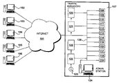
- FIG. 1 shows an embodiment of the invention for accessing data over the Internet
- FIG. 2 shows details of the hardware configuration for a specific traffic manager
- FIG. 3 shows procedures for implementing operation of the system
- FIG. 4 shows traffic manager configuration procedures
- FIG. 5 shows a mapping of instructions and data held within the main memory shown in FIG. 2 ;
- FIG. 6 shows an example of a transition table of the type held in the memory shown in FIG. 7 ;
- FIG. 7 illustrates the complete set of permutations for system availability for the transition table shown in FIG. 8 ;
- FIG. 8 details steps carried out in FIG. 6 for generating transition tables
- FIG. 9 details steps carried out in FIG. 10 for assigning IP addresses
- FIG. 10 illustrates the results produced from the operation of the procedure illustrated in FIG. 11 ;
- FIG. 11 details steps carried out in FIG. 10 to generate an initial transition table
- FIG. 12 shows exemplary results of the procedure performed in accordance with FIG. 11 ;
- FIG. 13 details steps carried out in FIG. 10 to finalise the transition table
- FIG. 14 details steps carried out in FIG. 13 to select a traffic manager
- FIG. 15 illustrates the procedure of FIG. 13 ;
- FIG. 16 details steps carried out in FIG. 5 for running a traffic management system
- FIG. 17 details steps carried out in FIG. 16 for checking traffic manager status
- FIG. 18 details steps carried out in FIG. 17 to reconfigure IP address assignments
- FIG. 19 illustrates a transition table in use.
- FIG. 1 A first figure.
- the Internet is illustrated at 101 and receives requests from many browsing clients, a small section of which are illustrated as browsing clients 102 to 106 .
- a service provider 107 includes servers 108 to 119 , traffic managers 120 to 123 , an administration station 124 , traffic manager instructions encoded onto a CD-ROM 125 or similar data carrying medium, and an internal network 126 .
- the service provider 107 has a single URL and is therefore configured to provide information from a popular website to a significantly large number of browsing clients.
- a domain name server (DNS) on the Internet associates this URL with several IP addresses, which are assigned to the traffic managers 120 to 123 .
- Each traffic manager has a different IP address or several IP addresses assigned to it.
- DNS domain name server
- Each traffic manager is thus considered to be responsible for a number of IP or network addresses.
- the traffic manager 120 receives a client request (an HTTP request) and analyses it, in part or completely, in order to decide which server 108 to 119 to convey the request to. It may decide this according to several criteria. For example, it may wish to simply spread the load, in which case it will choose the least loaded server. Traffic management, however, usually involves selecting servers on the basis of their functionality. In such a scenario, servers are grouped into pools. A first pool may serve static web pages, a second pool may serve dynamic content and a third pool may serve secured data over an HTTPS connection. The traffic manager 120 chooses which to access, based upon the type of request. Thus, this additional functionality may be considered as identifying the difference between traffic management compared to basic load balancing.
- the administration station 124 is used to remotely configure the traffic managers and the servers, such that it is not necessary to provide the traffic managers and servers with an output monitor or a keyboard input etc. Consequently, these systems have a hardware implementation that consists of a one- or two-unit rack mounted device connected to a network.
- the administration station is also used for installing instructions, including server instructions and traffic managing instructions.
- the CD-ROM 125 containing traffic managing instructions may be loaded directly onto the traffic managers 120 to 123 if they have CD-ROM drives, or instructions from the CD-ROM can be installed from the CD-ROM drive of the administration station 124 via the network 126 onto the traffic managers 120 to 123 .
- service requests are managed in a system having many servers for serving clients in response to at least one address, under the supervision of a set of traffic management systems.
- Each incoming address is assigned to a traffic manager and each of the traffic management systems is configured such that firstly it intermittently transmits its availability to the other traffic management systems in the set. Secondly, it identifies a change in the availability of the other traffic managers in the set. Thirdly, it modifies its address assignment in response to the identified change of availability. In this way, it is possible to balance incoming service request management against the availability of the traffic management systems.
- Each traffic manager 120 to 123 is provided with local information telling it which of the available servers should be accessed in response to receiving each specific IP address.
- Each traffic management system issues a multicast on a periodic basis informing the other traffic management systems to the effect that the traffic management system is available, although this transmitting of a signal to confirm functionality could take other forms than multicasting. Failure to receive a multicast in this way identifies to the other servers that availability has been lost. Each is then provided with information allowing a reconfiguration such that each is made aware of the IP addresses that it is now additionally responsible for.
- FIG. 2 Details of the hardware configuration for a specific traffic manager 120 is illustrated in FIG. 2 .
- All traffic managers 120 to 123 are substantially the same, and the servers 108 to 119 are similarly configured.
- the central processing unit 201 may be a Pentium 6 running at 5.2 gigahertz and includes on-chip primary and secondary cache, to facilitate access to frequently used instructions and data.
- a main memory 202 provides, for example, 2 gigabytes of dynamic RAM, in which instructions and data are stored for regular access while the system is operating.
- a hard disk drive 203 provides typically 60 gigabytes of non-volatile storage of instructions and configuration data. The disk 203 also provides storage for infrequently accessed data, such as configuration files, that are loaded into main memory when the system is initialised.
- a CD-ROM drive 204 is shown which, as previously stated, is configured to receive the data carrying medium, such as a CD-ROM, so as to facilitate the loading of instructions for implementing the traffic management functionality.
- Communication to network 126 is provided via a network interface card 205 .
- Procedures for implementing operation of the system are illustrated in FIG. 3 .
- the procedures illustrated in FIG. 3 are performed primarily via the administration station 124 and are relevant to the configuration of the traffic managers.
- step 301 power is supplied to the traffic managers and at step 302 a question is asked as to whether the instructions for traffic management have been installed. If not installed, a further question is asked at step 303 as to whether CD-ROM or network installation is to take place, resulting in the installation of instructions via the network at step 304 or installation of instructions from CD-ROM or a similar data-carrying medium at step 305 .
- a question is asked as to whether the traffic managers are to be configured, and when answered in the affirmative the configuration procedure takes place at step 307 .
- the traffic manager procedures are implemented at step 308 whereafter, at step 309 , the question is asked as to whether a reconfiguration is to take place. When answered in the affirmative, control is returned to step 307 and traffic manager reconfiguration is implemented. Alternatively, if no further operations are required a power-down procedure may be implemented at step 310 .
- Traffic manager configuration procedures identified at step 307 , are detailed in FIG. 4 .
- server configuration takes place. This involves defining server pools and other standard configuration information.
- a definition is made as to which traffic managers are available.
- names allocated to the traffic managers are also identified so that they can be referred to in the transition table that is created.
- Names for the traffic managers in this embodiment typically take the form of a.tm.amz.com.
- Procedure 402 also involves obtaining a list of the IP addresses that are to be shared among the traffic managers. Furthermore, it is also necessary to define which machines are initially active or on standby. For the purposes of an illustrative example, traffic managers 120 to 122 are considered to be active and traffic manager 123 is considered to be on standby. This data is supplied via the administration station 124 and then conveyed to the traffic managers over the network 126 .
- configuration data is generated that specifies the responsibility of traffic management systems for network addresses dependent upon the status of each of the systems.
- the data takes the form of a transition table for all permutations of traffic manager availability.
- the transition table defines how IP addresses will be reassigned when one (or possibly several) of the traffic managers fail.
- the administration station conveys data to the traffic managers such that they are placed in a condition where they are able to configure themselves using the data that has been provided.
- Each traffic manager creates its own copy of the transition table by running a copy of the same algorithm.
- the transition table it would be possible for the transition table to be generated once, possibly at the administration station 124 , and then distributed to the traffic managers. In either case, the transition tables at each of the traffic manager systems are substantially the same, thereby enabling traffic managers to self-configure without the need to communicate with other traffic managers when reaching a decision about new IP address configuration required as a result of a change in availability of traffic managers.
- an operating system such as Linux® or an alternative, is loaded at 501 .
- the traffic managing instructions themselves are loaded at 502 , including instructions for generating a transition table which are illustrated at 503 .
- the transition table itself is illustrated as being located at 504 and a table of scores used during the creation of the transition table is held at location 505 .
- a list of available traffic managers is held at location 506 and location 507 provides space for the storage of traffic management data.
- FIG. 6 An example of a transition table of the type held at location 503 is illustrated at FIG. 6 .
- the transition table shown in FIG. 6 is appropriate for three traffic management systems and three IP addresses.
- the IP addresses are shown as numbers 1 , 2 and 5 and the traffic management systems are named as letters, specifically a, b and c.
- the IP addresses will actually take the form 12.103.1.2 and so on, and the names of the traffic management systems will be of the form previously described.
- IP address 1 is assigned to traffic management system a. However, if a is not available, IP address 1 gets assigned to traffic management system b. Similarly, if b is not available, IP address 1 is assigned to traffic management system c.
- Row 602 concerns the assignment for IP address 2 .
- IP address 2 is assigned to traffic management system b if system b is available.
- IP address 2 is assigned to traffic management system c.
- IP address is assigned to machine a.
- IP address 5 is normally assigned to traffic management system c if system c is available. However, if system c is not available, IP address will be assigned to system a. Finally, if system a is not available, IP address 5 will be assigned to system b.
- the transition covers all possible combinations of traffic management system failure and ensures that an IP address is assigned accordingly to one of the remaining machines.
- the complete set of permutations for system availability is illustrated in FIG. 7 .
- a property of the transition tables is that when a machine fails, the only IP address movements that occur are those from the failed machine to the other machines in the cluster. Similarly, when a machine becomes available again, the only movements are onto the new machine. This avoids unnecessary IP address movements, thus reducing the chance of random connections being dropped.
- a traffic management system is considered to be non-functional or not operational if it stops multicasting on the network, for whatever reason. Possible reasons could be a software crash, a power outage, a hardware failure, and so on.
- FIG. 7 illustrates the consequences of implementing the table of FIG. 6 with respect to all possible availability states.
- Line 701 illustrates the operating condition in which traffic management systems a, b and c are all operational. Under these conditions, IP address 1 will be allocated to system a, IP address 2 will be allocated to system b and IP address system c will be allocated to system c.
- Line 702 identifies the condition where system c is no longer operational. The result is determined by line 603 of FIG. 6 which states that traffic management system a will be adopted for IP address 5 should a failure occur on system c. Thus, as illustrated at line 702 , system a is now responsible for IP addresses 1 and 5 , with b still retaining responsibility for IP address 2 and no IP addresses being allocated to system c.
- traffic management system b is now allocated IP address 1 and system c retains IP address 5 , with system a not dealing with any IP addresses.
- Lines 705 , 706 and 707 identify the condition where traffic management systems a, b and c respectively are the only ones operational. As illustrated, under these conditions, the single operational traffic management system will be allocated all three.
- transition table to decide the responsibilities of the traffic management systems means that whenever a particular combination of functional and non-functional traffic management systems occurs, the responsibility of the functional traffic management systems for network addresses is identical. In particular, if traffic management systems become unavailable and then become available again, each system will be responsible for the same IP addresses after this occurs as before.
- each IP address is assigned to an active traffic manager, and at step 802 an initial transition table with unfixed transition row order is generated. At step 803 this transition table is finalised by re-ordering the transition rows.
- the re-ordering procedure attempts to evenly distribute traffic between the working machines in the cluster, effectively creating a good transition table as distinct from a bad one. For example, if as the result of a machine failure one machine is responsible for four addresses and another has only one, this is not a very even distribution. Therefore a good transition table may be defined as one where for each state the difference between the number of addresses on each working machine is preferably at most one.
- Procedure 801 for assigning IP addresses is detailed in FIG. 9 .
- step 901 all of the active traffic management systems are identified. This consists of systems a, b and c, but not d which is considered to be inactive. In this example, a, b and c may be assumed to correspond to systems 120 , 121 and 122 . These three are active and will be initially assigned IP addresses. System 123 in FIG. 1 may be considered as the d system and is presently on standby and remains on standby when all of the other systems are working.
- the fixed IP addresses are assigned. Usually one system, although it may be more, is given an initial IP address as a starting point for the procedure.
- the traffic management systems are sorted alphabetically by referring to their names which, in this example, gives the order a, b, c.
- the next unassigned IP address is selected. Thus, the procedure starts off with IP address 2 , then 5 , then 6 on remaining iterations.
- next traffic manager is assigned to the IP address selected at step 904 .
- a was assigned at step 902 so the next available system is b. Consequently, IP address 2 is assigned to system b and, on the next iteration, IP address 5 is assigned to c.
- IP address 6 On the final iteration to allocate IP address 6 , no traffic management systems remain, so the procedure returns to the start of the system alphabetical list. Consequently, IP address 6 is allocated to system a.
- all of the IP addresses will have been considered, resulting in the question asked at step 906 being answered in the negative.
- FIG. 10 An illustration of the results produced from the operation of the procedure illustrated in FIG. 9 is shown in FIG. 10 .
- IP address 1 has been allocated to system a
- IP address 2 has been allocated to system b
- IP address 5 has been allocated to system c
- IP address 6 has been allocated to system a.
- FIG. 11 Details of the procedure identified at step 802 of FIG. 8 are shown in FIG. 11 .
- step 801 For this procedure, all of the traffic management systems, both active and standby, are considered, in contrast to step 801 during which only the active systems were considered and placed into the transition table.
- the IP addresses are sorted firstly by the number of times they were allocated to traffic managers during step 801 , and secondly by alphabetical order.
- d has not been allocated at all
- b and c have been allocated once
- a has been allocated twice, giving an ordering of d, b, c, a.
- an IP address is selected and at step 1103 all traffic management systems not yet allocated to this IP address are identified. On the first iteration this step will identify systems b, c and d as systems not yet allocated to IP address 1 .
- the identified systems are sorted according to the ordering identified at step 1101 .
- the identified systems are ordered d, b, c.
- any systems that have the same score as the system already allocated to that row are sorted so that systems coming alphabetically after the allocated system come before systems coming alphabetically before the allocated system.
- the ordering identified at step 1101 would be i, f, g, h, e.
- the ordering for the rest of that row would be i, h, f, e.
- step 1105 the remainder of the transition table rows are filled according to the system ordering identified at step 1104 .
- step 1106 a question is asked as to whether another IP address is to be considered and when answered in the affirmative control is returned to step 1102 where the next IP address is selected and the procedures iterated again.
- the first row 1201 shows an allocation, for IP address 1 , of a, d, b, c.
- the order at row entry 1202 for IP address 2 is b, d, c, a.
- the ordering at row 1203 for IP address 5 is c, d, b, a.
- an ordering of a, d, b, c is shown at row 1204 for IP address 6 .
- the first column contains fixed system names. However, columns 2 to 6 may need modification in order to improve even distribution following system failure.
- Procedure 803 for finalising the transition table is detailed in FIG. 13 .
- the first column of the transition table is defined as being fixed with the remaining three columns being considered as unfixed.
- allocation of system a for IP address 1 is fixed but the allocation of d, b and c are considered to be unfixed.
- the first unfixed column which on the first iteration is the second column, is selected, and at step 1303 the next row of the transition table, which on the first iteration is the first row, is selected.
- the contents of this row are divided into two sets: a fixed set containing fixed traffic managers, and an unfixed set containing unfixed traffic managers.
- the fixed set is [a]
- the unfixed set is [d b c].
- a score is obtained for each traffic manager in the unfixed set and the traffic manager with the lowest score is selected.
- the scoring method is described in FIG. 14 .
- the unfixed set is permuted such that the selected traffic manager becomes the first in the set.
- traffic manager b has the lowest score and thus the unfixed set [d b c] on the fourth line is permuted to be [b d c].
- the selected traffic manager is then fixed.
- step 1307 a question is asked as to whether there is another transition table row, and if this question is answered in the affirmative then control is returned to step 1303 where the row is selected. If it is answered in the negative then all the traffic managers in the selected column have been fixed.
- step 1308 a question is asked as to whether there is another unfixed column in the table, and if this question is answered in the affirmative control is returned to step 1302 where it is selected. Alternatively, the question is answered in the negative and step 803 is concluded.
- FIG. 14 details step 1305 where each unfixed traffic manager on a row is scored, and FIG. 15 shows the algorithm being used on the example transition table.
- the first row is selected, as shown at 1501 .
- the fixed and unfixed sets are [a] and [d b c].
- the first traffic manager in the unfixed set is selected, and at step 1402 each traffic manager in the fixed set is combined with this selected traffic manager.
- the selected traffic manager is d, giving the single pair [a d].
- the fixed set contains more than one traffic manager there will be a combination of pairs.
- the score for each of these combinations is looked up in a table of scores and these scores are summed to give a score for the selected traffic manager. This table is obtained by counting, for a combination [x y], how many times y has occurred immediately after x in a fixed position.
- the scores for all combinations will be zero, since only the first column is fixed.
- step 1404 a question is asked as to whether there is another traffic manager in the unfixed set, and if this question is answered in the affirmative then control is returned to step 1401 where the next traffic manager is selected. Further iterations of steps 1401 to 1403 give the pairs [a b] and [a c], each of which on this first iteration have a score of zero, as shown at 1503 .
- the first traffic manager with the lowest score is selected.
- each of the pairs has a score of zero and so the first pair with the lowest score is [a d].
- the second traffic manager in this pair, ie d is identified as the lowest scoring traffic manager.
- the score of this pair is incremented by 1 in the scoring table at step 1406 , as shown at 1504 , because it now occurs in the fixed columns. It is necessary that it is the first lowest-scored traffic manager in the set that is selected, in order that each system constructs an identical transition table.
- the pairs available in the second row are [b d], [b c] and [b a]. Since all of these combinations score zero, d is again the selected traffic manager.
- the pairs available in the third row are [c d], [c b] and [c a]. Again, all of these pairs score zero and so d is the selected traffic manager.
- the pairs are [a d], [a b] and [a c]. However in this case [a d] has a score of one, since d has been fixed as the second value in the first row, meaning that the first lowest scoring combination is [a b], giving b as the selected traffic manager.
- steps 1302 to 1308 gives a table with a fixed second column as shown at 1505 .
- the pairs [a d], [b d], [c d] and [a b] now all have a score of one in the scoring table.
- steps 1302 to 1308 there are two traffic managers in the fixed set and two in the unfixed set, as shown at 1506 .
- the available combinations of pairs for the first row are [a b]+[d b], and [a c]+[d c].
- the scores for the combinations are summed. Since [a b] occurs in row 6 , [a c]+[d c] has the lower score of zero, and c is the selected traffic manager. Both of the pairs [a c] and [d c] are incremented by one in the scoring table.
- the combinations are [b c]+[d c], and [b a]+[d a].
- the pair [d c] scores one, and so a is the selected traffic manager.
- the combinations are [c b]+[d b], and [c a]+[d a].
- the pair [d a] scores one, meaning that b is the selected traffic manager.
- the combinations are [a d]+[b d], and [a c]+[b c].
- the pairs [a d] and [b d] both score one, giving a combined score of two, meaning that c is the selected traffic manager.
- Procedures 308 for running the traffic management systems are detailed in FIG. 16 .
- the procedures detailed in FIG. 16 identify what occurs on an individual traffic management system, such as system 120 .
- the same operations are performed in parallel on all of the working traffic management systems, with the exception of the standby system or systems which do not carry out any actual traffic managing procedures.
- Three separate threads of execution occur, shown as individual blocks 1601 , 1602 and 1603 .
- Block 1601 represents periodic multicasting of status conditions to the other traffic management systems. This multicasting process transmits a system status. If a system develops a fault, it ceases transmitting the multicast. Such a procedure operates in a fail-safe way given that, if, for example the system develops a serious fault such as the failure of a power supply, it will be unable to transmit the multicast signal anyway.
- Block 1602 represents periodic checking of traffic manager status. This process listens for multicast signals from other traffic managers, building up a list 506 of all traffic managers that have recently transmitted a multicast. IP address reconfiguration is performed if a traffic manager appears or disappears from this list.
- Block 1603 represents traffic management operations performed by all active traffic managers, including routing client requests to the servers 108 to 119 according to client requirements.
- FIG. 17 details process 1602 for checking traffic manager status.
- a question is asked as to whether the status of any traffic manager has changed. This is performed by examining the list of traffic managers 506 which have recently transmitted a multicast. If this has changed then IP address reconfiguration may be required. This examination also includes the system doing the checking, so that if a system has recently come online it will receive its own multicast and reconfigure IP addresses accordingly.
- step 1702 the transition table 504 is consulted and IP address assignments are reconfigured if necessary.
- the process pauses before returning to step 1701 . During this pause, interrupts generated by reception of IP multicasts from other machines will be accumulated, automatically updating the list of traffic managers 506 that are available.
- FIG. 18 details step 1702 where IP addresses are reconfigured.
- the effect of step 1702 is to check whether the process needs to add or remove one or several IP address assignments.
- a traffic manager fails, there is the possibility that the traffic manager on which this process is running needs to take over one or more IP addresses.
- the traffic manager on which this process is running may need to release an IP address.
- the first row in transition table 504 is selected and at step 1802 the traffic manager in the first column is selected.
- a question is asked as to whether this traffic manager is functional, and if this questions is answered in the negative then at step 1804 the next functional traffic manager in the row is identified.
- a question is asked as to whether the identified traffic manager is the traffic manager on which the process is running, and if this question is answered in the affirmative then at step 1806 a further question is asked as to whether the IP address for the selected row is already assigned to the traffic manager. If this question is answered in the negative then the IP address is assigned. Control is then directed to step 1811 .
- step 1805 If the question asked at step 1805 is answered in the negative, to the effect that the identified traffic manager is not the traffic manager on which the process is running, then at step 1808 a question is asked as to whether the IP address for the selected row is assigned to the traffic manager on which the process is running. If this question is answered in the affirmative then at step 1809 the IP address is released. Control is then directed to step 1811 .
- step 1810 a question is asked as to whether there is another column in the transition table, and if this question is answered in the affirmative then control is returned to step 1802 and the traffic manager in the next column of the row is selected.
- step 1806 If the question is answered in the negative, or if the question asked at step 1806 is answered in the affirmative, a question is asked as to whether there is another row in the transition table. If this question is answered in the affirmative then control is returned to step 1801 and the next row is selected. Alternatively, step 1702 is completed.
- FIG. 19 illustrates the effect of using a transition table.
- the service provider 107 includes traffic managers 120 to 123 that route traffic between servers 108 to 119 .
- Table 504 on system 120 is shown with real IP addresses and traffic manager domain names.
- Tables 1901 on system 121 , 1902 on system 122 and 1903 on system 123 are identical because they were constructed using the same algorithm.
- the transition table is constructed with traffic manager 123 , which has the domain name d.tm.amz.com, configured as a standby machine.
- traffic manager 123 which has the domain name d.tm.amz.com, configured as a standby machine.
- Other configurations are possible. For example, all four traffic managers could be active. A larger number of traffic managers could be used, with all active or with some on standby.
Abstract
Description
Claims (22)
Applications Claiming Priority (2)
| Application Number | Priority Date | Filing Date | Title |
|---|---|---|---|
| GB0410151.5 | 2004-05-07 | ||
| GBGB0410151.5A GB0410151D0 (en) | 2004-05-07 | 2004-05-07 | Load balancing & traffic management |
Publications (2)
| Publication Number | Publication Date |
|---|---|
| US20050262238A1 US20050262238A1 (en) | 2005-11-24 |
| US7523178B2 true US7523178B2 (en) | 2009-04-21 |
Family
ID=32482803
Family Applications (3)
| Application Number | Title | Priority Date | Filing Date |
|---|---|---|---|
| US11/124,835 Active 2026-07-06 US7523178B2 (en) | 2004-05-07 | 2005-05-09 | Tolerating failure of traffic management systems |
| US11/124,807 Active 2027-12-26 US8635265B2 (en) | 2004-05-07 | 2005-05-09 | Communicating between a server and clients |
| US11/124,830 Abandoned US20050265317A1 (en) | 2004-05-07 | 2005-05-09 | Managing the flow of data traffic |
Family Applications After (2)
| Application Number | Title | Priority Date | Filing Date |
|---|---|---|---|
| US11/124,807 Active 2027-12-26 US8635265B2 (en) | 2004-05-07 | 2005-05-09 | Communicating between a server and clients |
| US11/124,830 Abandoned US20050265317A1 (en) | 2004-05-07 | 2005-05-09 | Managing the flow of data traffic |
Country Status (2)
| Country | Link |
|---|---|
| US (3) | US7523178B2 (en) |
| GB (5) | GB0410151D0 (en) |
Cited By (4)
| Publication number | Priority date | Publication date | Assignee | Title |
|---|---|---|---|---|
| US20080168301A1 (en) * | 2007-01-10 | 2008-07-10 | Inventec Corporation | Method of automatically adjusting storage sources for server a system |
| US20090265766A1 (en) * | 2008-04-17 | 2009-10-22 | Zeus Technology Limited | Supplying Web Pages |
| US20210392059A1 (en) * | 2015-06-05 | 2021-12-16 | Cisco Technology, Inc. | Auto update of sensor configuration |
| US11936663B2 (en) | 2015-06-05 | 2024-03-19 | Cisco Technology, Inc. | System for monitoring and managing datacenters |
Families Citing this family (89)
| Publication number | Priority date | Publication date | Assignee | Title |
|---|---|---|---|---|
| US7343413B2 (en) | 2000-03-21 | 2008-03-11 | F5 Networks, Inc. | Method and system for optimizing a network by independently scaling control segments and data flow |
| US8380854B2 (en) | 2000-03-21 | 2013-02-19 | F5 Networks, Inc. | Simplified method for processing multiple connections from the same client |
| WO2006134373A2 (en) | 2005-06-15 | 2006-12-21 | Solarflare Communications Incorporated | Reception according to a data transfer protocol of data directed to any of a plurality of destination entities |
| US7684349B2 (en) * | 2005-07-26 | 2010-03-23 | International Business Machines Corporation | Method and system for transparently controlling the behavior of service methods in a service oriented architecture |
| US8943181B2 (en) * | 2005-11-29 | 2015-01-27 | Ebay Inc. | Method and system for reducing connections to a database |
| US8028039B1 (en) * | 2005-12-23 | 2011-09-27 | Reflexis Systems, Inc. | System and method for communicating data between wireless mobile hand-held computer and a back-end computer system |
| EP1821486B1 (en) * | 2006-02-17 | 2015-07-29 | Mitel Networks Corporation | Method for sharing resources over a network |
| US8347286B2 (en) * | 2007-07-16 | 2013-01-01 | International Business Machines Corporation | Method, system and program product for managing download requests received to download files from a server |
| US9164784B2 (en) * | 2007-10-12 | 2015-10-20 | International Business Machines Corporation | Signalizing an external event using a dedicated virtual central processing unit |
| US8972177B2 (en) | 2008-02-26 | 2015-03-03 | Microsoft Technology Licensing, Llc | System for logging life experiences using geographic cues |
| US8015144B2 (en) | 2008-02-26 | 2011-09-06 | Microsoft Corporation | Learning transportation modes from raw GPS data |
| US7930427B2 (en) * | 2008-03-03 | 2011-04-19 | Microsoft Corporation | Client-side load balancing |
| US8966121B2 (en) * | 2008-03-03 | 2015-02-24 | Microsoft Corporation | Client-side management of domain name information |
| US8458298B2 (en) * | 2008-03-03 | 2013-06-04 | Microsoft Corporation | Failover in an internet location coordinate enhanced domain name system |
| US7991879B2 (en) | 2008-03-03 | 2011-08-02 | Microsoft Corporation | Internet location coordinate enhanced domain name system |
| US8806053B1 (en) | 2008-04-29 | 2014-08-12 | F5 Networks, Inc. | Methods and systems for optimizing network traffic using preemptive acknowledgment signals |
| JP4582203B2 (en) * | 2008-06-06 | 2010-11-17 | コニカミノルタビジネステクノロジーズ株式会社 | Image forming apparatus, communication control method and communication control program in the same |
| EP2161896A1 (en) | 2008-09-05 | 2010-03-10 | Zeus Technology Limited | Supplying data files to requesting stations |
| EP2187586A1 (en) | 2008-11-14 | 2010-05-19 | Zeus Technology Limited | Facilitating the transmission of electronic mail |
| US9063226B2 (en) * | 2009-01-14 | 2015-06-23 | Microsoft Technology Licensing, Llc | Detecting spatial outliers in a location entity dataset |
| US9009177B2 (en) | 2009-09-25 | 2015-04-14 | Microsoft Corporation | Recommending points of interests in a region |
| US10721269B1 (en) | 2009-11-06 | 2020-07-21 | F5 Networks, Inc. | Methods and system for returning requests with javascript for clients before passing a request to a server |
| US8868961B1 (en) | 2009-11-06 | 2014-10-21 | F5 Networks, Inc. | Methods for acquiring hyper transport timing and devices thereof |
| US20110196887A1 (en) * | 2010-02-08 | 2011-08-11 | Google Inc. | Light-Weight Network Traffic Cache |
| US8612134B2 (en) | 2010-02-23 | 2013-12-17 | Microsoft Corporation | Mining correlation between locations using location history |
| US9261376B2 (en) | 2010-02-24 | 2016-02-16 | Microsoft Technology Licensing, Llc | Route computation based on route-oriented vehicle trajectories |
| US10288433B2 (en) * | 2010-02-25 | 2019-05-14 | Microsoft Technology Licensing, Llc | Map-matching for low-sampling-rate GPS trajectories |
| US8719198B2 (en) | 2010-05-04 | 2014-05-06 | Microsoft Corporation | Collaborative location and activity recommendations |
| US9593957B2 (en) | 2010-06-04 | 2017-03-14 | Microsoft Technology Licensing, Llc | Searching similar trajectories by locations |
| US9141625B1 (en) | 2010-06-22 | 2015-09-22 | F5 Networks, Inc. | Methods for preserving flow state during virtual machine migration and devices thereof |
| US10015286B1 (en) | 2010-06-23 | 2018-07-03 | F5 Networks, Inc. | System and method for proxying HTTP single sign on across network domains |
| US8908545B1 (en) | 2010-07-08 | 2014-12-09 | F5 Networks, Inc. | System and method for handling TCP performance in network access with driver initiated application tunnel |
| US8347100B1 (en) | 2010-07-14 | 2013-01-01 | F5 Networks, Inc. | Methods for DNSSEC proxying and deployment amelioration and systems thereof |
| US9083760B1 (en) | 2010-08-09 | 2015-07-14 | F5 Networks, Inc. | Dynamic cloning and reservation of detached idle connections |
| US8886981B1 (en) | 2010-09-15 | 2014-11-11 | F5 Networks, Inc. | Systems and methods for idle driven scheduling |
| US8804504B1 (en) | 2010-09-16 | 2014-08-12 | F5 Networks, Inc. | System and method for reducing CPU load in processing PPP packets on a SSL-VPN tunneling device |
| US9554276B2 (en) | 2010-10-29 | 2017-01-24 | F5 Networks, Inc. | System and method for on the fly protocol conversion in obtaining policy enforcement information |
| WO2012058486A2 (en) | 2010-10-29 | 2012-05-03 | F5 Networks, Inc. | Automated policy builder |
| US8825813B2 (en) | 2010-12-28 | 2014-09-02 | Microsoft Corporation | Distributed network coordinate system based on network performance |
| US10135831B2 (en) * | 2011-01-28 | 2018-11-20 | F5 Networks, Inc. | System and method for combining an access control system with a traffic management system |
| US9712340B2 (en) * | 2011-02-28 | 2017-07-18 | Red Hat, Inc. | Using a shared data store for peer discovery |
| US8700747B2 (en) * | 2011-04-19 | 2014-04-15 | Schneider Electric It Corporation | System and method for automatically addressing devices in a multi-drop network |
| US9246819B1 (en) | 2011-06-20 | 2016-01-26 | F5 Networks, Inc. | System and method for performing message-based load balancing |
| US20130024543A1 (en) * | 2011-07-19 | 2013-01-24 | Infosys Limited | Methods for generating multiple responses to a single request message and devices thereof |
| FR2978637B1 (en) * | 2011-07-29 | 2014-02-14 | Sagemcom Energy & Telecom Sas | METHOD FOR MANAGING ACCESS TO A SET OF RESOURCES DELIVERED BY AN ELECTRONIC DEVICE |
| GB2495557A (en) * | 2011-10-14 | 2013-04-17 | Riverbed Technology Inc | Routing network traffic requests to provide load balancing using hashes derived from attributes of the requests |
| WO2013086214A1 (en) | 2011-12-06 | 2013-06-13 | Seven Networks, Inc. | A system of redundantly clustered machines to provide failover mechanisms for mobile traffic management and network resource conservation |
| US9754226B2 (en) | 2011-12-13 | 2017-09-05 | Microsoft Technology Licensing, Llc | Urban computing of route-oriented vehicles |
| US20130166188A1 (en) | 2011-12-21 | 2013-06-27 | Microsoft Corporation | Determine Spatiotemporal Causal Interactions In Data |
| US9270766B2 (en) | 2011-12-30 | 2016-02-23 | F5 Networks, Inc. | Methods for identifying network traffic characteristics to correlate and manage one or more subsequent flows and devices thereof |
| US20130185378A1 (en) * | 2012-01-18 | 2013-07-18 | LineRate Systems, Inc. | Cached hash table for networking |
| US10230566B1 (en) | 2012-02-17 | 2019-03-12 | F5 Networks, Inc. | Methods for dynamically constructing a service principal name and devices thereof |
| US9231879B1 (en) | 2012-02-20 | 2016-01-05 | F5 Networks, Inc. | Methods for policy-based network traffic queue management and devices thereof |
| US9172753B1 (en) | 2012-02-20 | 2015-10-27 | F5 Networks, Inc. | Methods for optimizing HTTP header based authentication and devices thereof |
| US10097616B2 (en) | 2012-04-27 | 2018-10-09 | F5 Networks, Inc. | Methods for optimizing service of content requests and devices thereof |
| US10091049B2 (en) * | 2012-08-17 | 2018-10-02 | F5 Networks, Inc. | Scripting for implementing policy-based traffic steering and management |
| US9265458B2 (en) | 2012-12-04 | 2016-02-23 | Sync-Think, Inc. | Application of smooth pursuit cognitive testing paradigms to clinical drug development |
| US10375155B1 (en) | 2013-02-19 | 2019-08-06 | F5 Networks, Inc. | System and method for achieving hardware acceleration for asymmetric flow connections |
| US9380976B2 (en) | 2013-03-11 | 2016-07-05 | Sync-Think, Inc. | Optical neuroinformatics |
| CN103533068B (en) * | 2013-10-22 | 2017-08-25 | 黎亮 | IP-based Task Autonomous equilibrium assignment group system |
| US10187317B1 (en) | 2013-11-15 | 2019-01-22 | F5 Networks, Inc. | Methods for traffic rate control and devices thereof |
| US11163572B2 (en) * | 2014-02-04 | 2021-11-02 | Micron Technology, Inc. | Memory systems and memory control methods |
| US10015143B1 (en) | 2014-06-05 | 2018-07-03 | F5 Networks, Inc. | Methods for securing one or more license entitlement grants and devices thereof |
| US11838851B1 (en) | 2014-07-15 | 2023-12-05 | F5, Inc. | Methods for managing L7 traffic classification and devices thereof |
| US20160028847A1 (en) * | 2014-07-23 | 2016-01-28 | Microsoft Technology Licensing, Llc | Establishing caches that provide dynamic, authoritative dns responses |
| US10122630B1 (en) | 2014-08-15 | 2018-11-06 | F5 Networks, Inc. | Methods for network traffic presteering and devices thereof |
| US10182013B1 (en) | 2014-12-01 | 2019-01-15 | F5 Networks, Inc. | Methods for managing progressive image delivery and devices thereof |
| US11895138B1 (en) | 2015-02-02 | 2024-02-06 | F5, Inc. | Methods for improving web scanner accuracy and devices thereof |
| US10834065B1 (en) | 2015-03-31 | 2020-11-10 | F5 Networks, Inc. | Methods for SSL protected NTLM re-authentication and devices thereof |
| US10505818B1 (en) | 2015-05-05 | 2019-12-10 | F5 Networks. Inc. | Methods for analyzing and load balancing based on server health and devices thereof |
| US11350254B1 (en) | 2015-05-05 | 2022-05-31 | F5, Inc. | Methods for enforcing compliance policies and devices thereof |
| CN105187512A (en) * | 2015-08-13 | 2015-12-23 | 航天恒星科技有限公司 | Method and system for load balancing of virtual machine clusters |
| US11757946B1 (en) | 2015-12-22 | 2023-09-12 | F5, Inc. | Methods for analyzing network traffic and enforcing network policies and devices thereof |
| US10404698B1 (en) | 2016-01-15 | 2019-09-03 | F5 Networks, Inc. | Methods for adaptive organization of web application access points in webtops and devices thereof |
| US11178150B1 (en) | 2016-01-20 | 2021-11-16 | F5 Networks, Inc. | Methods for enforcing access control list based on managed application and devices thereof |
| US10797888B1 (en) | 2016-01-20 | 2020-10-06 | F5 Networks, Inc. | Methods for secured SCEP enrollment for client devices and devices thereof |
| US10791088B1 (en) | 2016-06-17 | 2020-09-29 | F5 Networks, Inc. | Methods for disaggregating subscribers via DHCP address translation and devices thereof |
| US10454807B2 (en) * | 2016-10-13 | 2019-10-22 | Futurewei Technologies, Inc. | Connection minimization for distributed system |
| US11063758B1 (en) | 2016-11-01 | 2021-07-13 | F5 Networks, Inc. | Methods for facilitating cipher selection and devices thereof |
| US10505792B1 (en) | 2016-11-02 | 2019-12-10 | F5 Networks, Inc. | Methods for facilitating network traffic analytics and devices thereof |
| US10812266B1 (en) | 2017-03-17 | 2020-10-20 | F5 Networks, Inc. | Methods for managing security tokens based on security violations and devices thereof |
| US10972453B1 (en) | 2017-05-03 | 2021-04-06 | F5 Networks, Inc. | Methods for token refreshment based on single sign-on (SSO) for federated identity environments and devices thereof |
| US10666602B2 (en) | 2017-05-05 | 2020-05-26 | Microsoft Technology Licensing, Llc | Edge caching in edge-origin DNS |
| US11122042B1 (en) | 2017-05-12 | 2021-09-14 | F5 Networks, Inc. | Methods for dynamically managing user access control and devices thereof |
| US11343237B1 (en) | 2017-05-12 | 2022-05-24 | F5, Inc. | Methods for managing a federated identity environment using security and access control data and devices thereof |
| US11122083B1 (en) | 2017-09-08 | 2021-09-14 | F5 Networks, Inc. | Methods for managing network connections based on DNS data and network policies and devices thereof |
| US11044200B1 (en) | 2018-07-06 | 2021-06-22 | F5 Networks, Inc. | Methods for service stitching using a packet header and devices thereof |
| EP3923146B1 (en) * | 2019-04-01 | 2023-11-22 | E-Jan Networks Co. | Communication system, information providing device, program, and information providing method |
| US20240061726A1 (en) * | 2022-08-22 | 2024-02-22 | Sap Se | Efficient connection pooling |
Citations (4)
| Publication number | Priority date | Publication date | Assignee | Title |
|---|---|---|---|---|
| US5661719A (en) * | 1995-10-19 | 1997-08-26 | Ncr Corporation | Method for activating a backup network management station in a network management system |
| US20020032760A1 (en) * | 1995-12-04 | 2002-03-14 | Wallace Matthews | Method and apparatus for tracking connection-oriented communications configurations |
| US20020120763A1 (en) * | 2001-01-11 | 2002-08-29 | Z-Force Communications, Inc. | File switch and switched file system |
| US20060059238A1 (en) * | 2004-05-29 | 2006-03-16 | Slater Charles S | Monitoring the flow of messages received at a server |
Family Cites Families (31)
| Publication number | Priority date | Publication date | Assignee | Title |
|---|---|---|---|---|
| JP2844591B2 (en) * | 1987-01-16 | 1999-01-06 | 株式会社日立製作所 | Digital signal processor |
| US6317775B1 (en) * | 1995-11-03 | 2001-11-13 | Cisco Technology, Inc. | System for distributing load over multiple servers at an internet site |
| US6324177B1 (en) * | 1997-05-02 | 2001-11-27 | Cisco Technology | Method and apparatus for managing connections based on a client IP address |
| US6067545A (en) * | 1997-08-01 | 2000-05-23 | Hewlett-Packard Company | Resource rebalancing in networked computer systems |
| US6105067A (en) * | 1998-06-05 | 2000-08-15 | International Business Machines Corp. | Connection pool management for backend servers using common interface |
| US20010042051A1 (en) * | 1998-06-26 | 2001-11-15 | Jeremey L. Barrett | Network transaction system for minimizing software requirements on client computers |
| US6438597B1 (en) * | 1998-08-17 | 2002-08-20 | Hewlett-Packard Company | Method and system for managing accesses to a data service system that supports persistent connections |
| US6411986B1 (en) * | 1998-11-10 | 2002-06-25 | Netscaler, Inc. | Internet client-server multiplexer |
| US20010049741A1 (en) * | 1999-06-18 | 2001-12-06 | Bryan D. Skene | Method and system for balancing load distribution on a wide area network |
| US6970913B1 (en) * | 1999-07-02 | 2005-11-29 | Cisco Technology, Inc. | Load balancing using distributed forwarding agents with application based feedback for different virtual machines |
| US6591290B1 (en) * | 1999-08-24 | 2003-07-08 | Lucent Technologies Inc. | Distributed network application management system |
| CA2293062A1 (en) * | 1999-12-22 | 2001-06-22 | Ibm Canada Limited-Ibm Canada Limitee | Efficient use of domain socket pairs in communication for tightly coupled transactions |
| US7069498B1 (en) * | 2000-01-31 | 2006-06-27 | Journyx, Inc. | Method and apparatus for a web based punch clock/time clock |
| US8380854B2 (en) * | 2000-03-21 | 2013-02-19 | F5 Networks, Inc. | Simplified method for processing multiple connections from the same client |
| US6950848B1 (en) * | 2000-05-05 | 2005-09-27 | Yousefi Zadeh Homayoun | Database load balancing for multi-tier computer systems |
| US7577834B1 (en) * | 2000-05-09 | 2009-08-18 | Sun Microsystems, Inc. | Message authentication using message gates in a distributed computing environment |
| US7039691B1 (en) * | 2000-06-02 | 2006-05-02 | Sun Microsystems, Inc. | Java virtual machine configurable to perform as a web server |
| US6807572B1 (en) * | 2000-08-31 | 2004-10-19 | Intel Corporation | Accessing network databases |
| WO2002019132A1 (en) * | 2000-09-01 | 2002-03-07 | Tut Systems, Inc. | A method and system to pre-compile configuration information for a data communications device |
| SE518479C2 (en) * | 2000-10-13 | 2002-10-15 | Ericsson Telefon Ab L M | Communication systems that support wireless communication of packet data and method and device related thereto |
| US7003572B1 (en) * | 2001-02-28 | 2006-02-21 | Packeteer, Inc. | System and method for efficiently forwarding client requests from a proxy server in a TCP/IP computing environment |
| US6947894B1 (en) * | 2001-05-31 | 2005-09-20 | Hall Aluminum Llc | User voice based resource saving preemption |
| US7216160B2 (en) * | 2001-10-31 | 2007-05-08 | Sun Microsystems, Inc. | Server-based application monitoring through collection of application component and environmental statistics |
| JP3808755B2 (en) * | 2001-11-07 | 2006-08-16 | 富士通株式会社 | Virtual machine with JIT compiler |
| US20030110154A1 (en) * | 2001-12-07 | 2003-06-12 | Ishihara Mark M. | Multi-processor, content-based traffic management system and a content-based traffic management system for handling both HTTP and non-HTTP data |
| US7506342B2 (en) * | 2002-07-23 | 2009-03-17 | Bea Systems, Inc. | System and method for implementing J2EE connector architecture |
| US7058717B2 (en) * | 2002-07-25 | 2006-06-06 | International Business Machines Corporation | Method and system for providing highly available services based on a load balancing policy and a reusable connection context object |
| US20040111506A1 (en) * | 2002-12-10 | 2004-06-10 | International Business Machines Corporation | System and method for managing web utility services |
| US7613822B2 (en) * | 2003-06-30 | 2009-11-03 | Microsoft Corporation | Network load balancing with session information |
| US7246174B2 (en) * | 2003-10-28 | 2007-07-17 | Nacon Consulting, Llc | Method and system for accessing and managing virtual machines |
| US20100211626A1 (en) * | 2004-01-12 | 2010-08-19 | Foundry Networks, Inc. | Method and apparatus for maintaining longer persistent connections |
-
2004
- 2004-05-07 GB GBGB0410151.5A patent/GB0410151D0/en not_active Ceased
-
2005
- 2005-05-06 GB GB0509255A patent/GB2414136B8/en active Active
- 2005-05-09 US US11/124,835 patent/US7523178B2/en active Active
- 2005-05-09 GB GBGB0509336.4A patent/GB0509336D0/en not_active Ceased
- 2005-05-09 GB GB0509338A patent/GB2414148A/en not_active Withdrawn
- 2005-05-09 US US11/124,807 patent/US8635265B2/en active Active
- 2005-05-09 US US11/124,830 patent/US20050265317A1/en not_active Abandoned
- 2005-05-09 GB GB0509335A patent/GB2413868B/en active Active
Patent Citations (4)
| Publication number | Priority date | Publication date | Assignee | Title |
|---|---|---|---|---|
| US5661719A (en) * | 1995-10-19 | 1997-08-26 | Ncr Corporation | Method for activating a backup network management station in a network management system |
| US20020032760A1 (en) * | 1995-12-04 | 2002-03-14 | Wallace Matthews | Method and apparatus for tracking connection-oriented communications configurations |
| US20020120763A1 (en) * | 2001-01-11 | 2002-08-29 | Z-Force Communications, Inc. | File switch and switched file system |
| US20060059238A1 (en) * | 2004-05-29 | 2006-03-16 | Slater Charles S | Monitoring the flow of messages received at a server |
Non-Patent Citations (2)
| Title |
|---|
| Collins et al: Achieving Scalable Cluster System Analysis and Management with a Gossip-based Network Service. 2001. IEEE Computer Soc., pp. 49-58. ISBN 0-7695-1321-2. |
| Tripathi et al: Secure Multi-Agent Coordination in a Network Monitoring System. 2003, Software engineering for large-scale multi-agent systems. pp. 251-266. ISBN 3-540-08772-9. |
Cited By (5)
| Publication number | Priority date | Publication date | Assignee | Title |
|---|---|---|---|---|
| US20080168301A1 (en) * | 2007-01-10 | 2008-07-10 | Inventec Corporation | Method of automatically adjusting storage sources for server a system |
| US20090265766A1 (en) * | 2008-04-17 | 2009-10-22 | Zeus Technology Limited | Supplying Web Pages |
| US8332515B2 (en) * | 2008-04-17 | 2012-12-11 | Riverbed Technology, Inc. | System and method for serving web pages |
| US20210392059A1 (en) * | 2015-06-05 | 2021-12-16 | Cisco Technology, Inc. | Auto update of sensor configuration |
| US11936663B2 (en) | 2015-06-05 | 2024-03-19 | Cisco Technology, Inc. | System for monitoring and managing datacenters |
Also Published As
| Publication number | Publication date |
|---|---|
| US20060031525A1 (en) | 2006-02-09 |
| GB0509338D0 (en) | 2005-06-15 |
| US8635265B2 (en) | 2014-01-21 |
| GB0509335D0 (en) | 2005-06-15 |
| GB2414148A8 (en) | 2007-05-21 |
| US20050262238A1 (en) | 2005-11-24 |
| US20050265317A1 (en) | 2005-12-01 |
| GB2414136B (en) | 2007-05-09 |
| GB0410151D0 (en) | 2004-06-09 |
| GB2414136A (en) | 2005-11-16 |
| GB0509336D0 (en) | 2005-06-15 |
| GB2414136B8 (en) | 2008-02-26 |
| GB2413868B (en) | 2007-08-29 |
| GB2413868A (en) | 2005-11-09 |
| GB2414148A (en) | 2005-11-16 |
| GB0509255D0 (en) | 2005-06-15 |
Similar Documents
| Publication | Publication Date | Title |
|---|---|---|
| US7523178B2 (en) | Tolerating failure of traffic management systems | |
| EP3811597B1 (en) | Zone redundant computing services using multiple local services in distributed computing systems | |
| US10791181B1 (en) | Method and apparatus for web based storage on-demand distribution | |
| CN109040212B (en) | Method, system, device and storage medium for accessing device to server cluster | |
| US6694406B2 (en) | Multiple processor data processing system with mirrored data for distributed access | |
| CN101118521B (en) | System and method for spanning multiple logical sectorization to distributing virtual input-output operation | |
| US8185905B2 (en) | Resource allocation in computing systems according to permissible flexibilities in the recommended resource requirements | |
| EP2288111A1 (en) | Managing client requests for data | |
| US8484416B2 (en) | High availability raid using low-cost direct attached raid controllers | |
| US20060156055A1 (en) | Storage network that includes an arbiter for managing access to storage resources | |
| WO2012068867A1 (en) | Virtual machine management system and using method thereof | |
| JP2007128511A (en) | Method and device for automatically evaluating and allocating resource in cell based system | |
| CN113037522A (en) | Container unit management method and related equipment | |
| US20100332532A1 (en) | Distributed directory environment using clustered ldap servers | |
| US8832215B2 (en) | Load-balancing in replication engine of directory server | |
| WO2013132910A1 (en) | Host providing system and host providing method | |
| CN107566466A (en) | Load-balancing method and device | |
| CN111131445B (en) | DHCP cluster scheduling method and DHCP cluster system | |
| CN116225655A (en) | Task scheduling method, device and storage medium | |
| CN104461705A (en) | Service access method, storage controllers and cluster storage system | |
| JP3782429B2 (en) | Load balancing system and computer management program | |
| EP2321931B1 (en) | Shared hosting using host name affinity | |
| JP2002009791A (en) | Dhcp server system for dynamically assigning ip address and dhcp server for dynamically assigning ip address | |
| US7558858B1 (en) | High availability infrastructure with active-active designs | |
| CN109327520A (en) | Establish the method and device that terminal is connect with server node |
Legal Events
| Date | Code | Title | Description |
|---|---|---|---|
| AS | Assignment |
Owner name: ZEUS TECHNOLOGY LIMITED, UNITED KINGDOM Free format text: ASSIGNMENT OF ASSIGNORS INTEREST;ASSIGNORS:REEVES, DAMIAN JOHN;MANSELL, BEN ROSS;GARRETT, OWEN JOHN;AND OTHERS;REEL/FRAME:016697/0296 Effective date: 20050920 |
|
| AS | Assignment |
Owner name: NOBLE VENTURE FINANCE II S.A., LUXEMBOURG Free format text: SECURITY AGREEMENT;ASSIGNOR:ZEUS TECHNOLOGY LIMITED;REEL/FRAME:021762/0937 Effective date: 20080925 |
|
| STCF | Information on status: patent grant |
Free format text: PATENTED CASE |
|
| AS | Assignment |
Owner name: NOBLE VENTURE FINANCE II S.A., LUXEMBOURG Free format text: DEED OF RELEASE;ASSIGNOR:ZEUS TECHNOLOGY LIMITED;REEL/FRAME:027592/0158 Effective date: 20110712 |
|
| AS | Assignment |
Owner name: RIVERBED TECHNOLOGY LIMITED, UNITED KINGDOM Free format text: ASSIGNMENT OF ASSIGNORS INTEREST;ASSIGNOR:ZEUS TECHNOLOGY LIMITED;REEL/FRAME:027603/0331 Effective date: 20111101 |
|
| AS | Assignment |
Owner name: RIVERBED TECHNOLOGY, INC., CALIFORNIA Free format text: ASSIGNMENT OF ASSIGNORS INTEREST;ASSIGNOR:RIVERBED TECHNOLOGY LIMITED;REEL/FRAME:027644/0888 Effective date: 20111201 |
|
| FEPP | Fee payment procedure |
Free format text: PAYOR NUMBER ASSIGNED (ORIGINAL EVENT CODE: ASPN); ENTITY STATUS OF PATENT OWNER: LARGE ENTITY |
|
| REMI | Maintenance fee reminder mailed | ||
| AS | Assignment |
Owner name: MORGAN STANLEY & CO. LLC, MARYLAND Free format text: SECURITY AGREEMENT;ASSIGNORS:RIVERBED TECHNOLOGY, INC.;OPNET TECHNOLOGIES, INC.;REEL/FRAME:029646/0060 Effective date: 20121218 |
|
| FPAY | Fee payment |
Year of fee payment: 4 |
|
| SULP | Surcharge for late payment | ||
| AS | Assignment |
Owner name: RIVERBED TECHNOLOGY, INC., CALIFORNIA Free format text: RELEASE OF PATENT SECURITY INTEREST;ASSIGNOR:MORGAN STANLEY & CO. LLC, AS COLLATERAL AGENT;REEL/FRAME:032113/0425 Effective date: 20131220 |
|
| AS | Assignment |
Owner name: JPMORGAN CHASE BANK, N.A., AS ADMINISTRATIVE AGENT, NEW YORK Free format text: PATENT SECURITY AGREEMENT;ASSIGNOR:RIVERBED TECHNOLOGY, INC.;REEL/FRAME:032421/0162 Effective date: 20131220 Owner name: JPMORGAN CHASE BANK, N.A., AS ADMINISTRATIVE AGENT Free format text: PATENT SECURITY AGREEMENT;ASSIGNOR:RIVERBED TECHNOLOGY, INC.;REEL/FRAME:032421/0162 Effective date: 20131220 |
|
| AS | Assignment |
Owner name: RIVERBED TECHNOLOGY, INC., CALIFORNIA Free format text: RELEASE BY SECURED PARTY;ASSIGNOR:JPMORGAN CHASE BANK, N.A., AS COLLATERAL AGENT;REEL/FRAME:035078/0354 Effective date: 20150303 |
|
| AS | Assignment |
Owner name: BROCADE COMMUNICATIONS SYSTEMS, INC., CALIFORNIA Free format text: ASSIGNMENT OF ASSIGNORS INTEREST;ASSIGNOR:RIVERBED TECHNOLOGY, INC.;REEL/FRAME:035097/0776 Effective date: 20150303 |
|
| AS | Assignment |
Owner name: MORGAN STANLEY SENIOR FUNDING, INC., AS COLLATERAL AGENT, NEW YORK Free format text: SECURITY INTEREST;ASSIGNOR:RIVERBED TECHNOLOGY, INC.;REEL/FRAME:035561/0363 Effective date: 20150424 Owner name: MORGAN STANLEY SENIOR FUNDING, INC., AS COLLATERAL Free format text: SECURITY INTEREST;ASSIGNOR:RIVERBED TECHNOLOGY, INC.;REEL/FRAME:035561/0363 Effective date: 20150424 |
|
| FPAY | Fee payment |
Year of fee payment: 8 |
|
| AS | Assignment |
Owner name: RIVERBED TECHNOLOGY, INC., CALIFORNIA Free format text: PARTIAL RELEASE OF SECURITY INTEREST IN PATENTS RECORDED AT R/F 035561/0363;ASSIGNOR:MORGAN STANLEY SENIOR FUNDING, INC., AS COLLATERAL AGENT;REEL/FRAME:041298/0876 Effective date: 20170106 |
|
| AS | Assignment |
Owner name: PULSE SECURE, LLC, CALIFORNIA Free format text: ASSIGNMENT OF ASSIGNORS INTEREST;ASSIGNOR:BROCADE COMMUNICATION SYSTEMS, INC.;REEL/FRAME:043604/0172 Effective date: 20170731 |
|
| AS | Assignment |
Owner name: KKR LOAN ADMINISTRATION SERVICES LLC, AS COLLATERAL AGENT, NEW YORK Free format text: SECURITY INTEREST;ASSIGNOR:PULSE SECURE, LLC;REEL/FRAME:053638/0220 Effective date: 20200824 |
|
| MAFP | Maintenance fee payment |
Free format text: PAYMENT OF MAINTENANCE FEE, 12TH YEAR, LARGE ENTITY (ORIGINAL EVENT CODE: M1553); ENTITY STATUS OF PATENT OWNER: LARGE ENTITY Year of fee payment: 12 |
|
| AS | Assignment |
Owner name: PULSE SECURE, LLC, CALIFORNIA Free format text: RELEASE OF SECURITY INTEREST : RECORDED AT REEL/FRAME - 053638-0220;ASSIGNOR:KKR LOAN ADMINISTRATION SERVICES LLC;REEL/FRAME:054559/0368 Effective date: 20201201 |
|
| AS | Assignment |
Owner name: MORGAN STANLEY SENIOR FUNDING, INC., AS COLLATERAL AGENT, MARYLAND Free format text: SECURITY INTEREST;ASSIGNORS:CELLSEC, INC.;PULSE SECURE, LLC;IVANTI, INC.;AND OTHERS;REEL/FRAME:054665/0062 Effective date: 20201201 Owner name: BANK OF AMERICA, N.A., AS COLLATERAL AGENT, ILLINOIS Free format text: SECURITY INTEREST;ASSIGNORS:CELLSEC, INC.;PULSE SECURE, LLC;INVANTI, INC.;AND OTHERS;REEL/FRAME:054665/0873 Effective date: 20201201 |