US7379052B1 - Hand-held computer control device - Google Patents

Hand-held computer control device Download PDF

Info

Publication number
US7379052B1
US7379052B1 US10/954,071 US95407104A US7379052B1 US 7379052 B1 US7379052 B1 US 7379052B1 US 95407104 A US95407104 A US 95407104A US 7379052 B1 US7379052 B1 US 7379052B1
Authority
US
United States
Prior art keywords
hand
user
control device
switch
left hand
Prior art date
Legal status (The legal status is an assumption and is not a legal conclusion. Google has not performed a legal analysis and makes no representation as to the accuracy of the status listed.)
Expired - Fee Related, expires
Application number
US10/954,071
Inventor
Terry L. Dellenger
Current Assignee (The listed assignees may be inaccurate. Google has not performed a legal analysis and makes no representation or warranty as to the accuracy of the list.)
Intel Corp
Original Assignee
Intel Corp
Priority date (The priority date is an assumption and is not a legal conclusion. Google has not performed a legal analysis and makes no representation as to the accuracy of the date listed.)
Filing date
Publication date
Application filed by Intel Corp filed Critical Intel Corp
Priority to US10/954,071 priority Critical patent/US7379052B1/en
Assigned to INTEL CORPORATION reassignment INTEL CORPORATION ASSIGNMENT OF ASSIGNORS INTEREST (SEE DOCUMENT FOR DETAILS). Assignors: BUOT, JOAN REY V., LIBAY, CARMELITO M., PIEDA, RUEL B.
Application granted granted Critical
Publication of US7379052B1 publication Critical patent/US7379052B1/en
Adjusted expiration legal-status Critical
Expired - Fee Related legal-status Critical Current

Links

Images

Classifications

    • GPHYSICS
    • G06COMPUTING; CALCULATING OR COUNTING
    • G06FELECTRIC DIGITAL DATA PROCESSING
    • G06F3/00Input arrangements for transferring data to be processed into a form capable of being handled by the computer; Output arrangements for transferring data from processing unit to output unit, e.g. interface arrangements
    • G06F3/01Input arrangements or combined input and output arrangements for interaction between user and computer
    • G06F3/02Input arrangements using manually operated switches, e.g. using keyboards or dials
    • G06F3/023Arrangements for converting discrete items of information into a coded form, e.g. arrangements for interpreting keyboard generated codes as alphanumeric codes, operand codes or instruction codes
    • G06F3/0233Character input methods
    • GPHYSICS
    • G06COMPUTING; CALCULATING OR COUNTING
    • G06FELECTRIC DIGITAL DATA PROCESSING
    • G06F3/00Input arrangements for transferring data to be processed into a form capable of being handled by the computer; Output arrangements for transferring data from processing unit to output unit, e.g. interface arrangements
    • G06F3/01Input arrangements or combined input and output arrangements for interaction between user and computer
    • G06F3/011Arrangements for interaction with the human body, e.g. for user immersion in virtual reality
    • G06F3/014Hand-worn input/output arrangements, e.g. data gloves
    • GPHYSICS
    • G06COMPUTING; CALCULATING OR COUNTING
    • G06FELECTRIC DIGITAL DATA PROCESSING
    • G06F3/00Input arrangements for transferring data to be processed into a form capable of being handled by the computer; Output arrangements for transferring data from processing unit to output unit, e.g. interface arrangements
    • G06F3/01Input arrangements or combined input and output arrangements for interaction between user and computer
    • G06F3/03Arrangements for converting the position or the displacement of a member into a coded form
    • G06F3/033Pointing devices displaced or positioned by the user, e.g. mice, trackballs, pens or joysticks; Accessories therefor
    • G06F3/0354Pointing devices displaced or positioned by the user, e.g. mice, trackballs, pens or joysticks; Accessories therefor with detection of 2D relative movements between the device, or an operating part thereof, and a plane or surface, e.g. 2D mice, trackballs, pens or pucks
    • G06F3/03549Trackballs

Definitions

  • the present invention relates to remote control devices and, more particularly, to a palm size, symmetrical, hand-held, control device adapted for easy, interchangeable retention in the grasp of and adjacent the palm of a user's right or left hand.
  • GUI Graphic User Interface
  • Pointing devices are a form of remote control device and are used, among many other uses, to move a cursor around on a computer screen.
  • pointing devices are typically equipped with one or more switches, buttons or similar devices that allow signals to be sent to a processor for interpretation into a command or commands for positioning a computer cursor or other computer controlled functions.
  • a mouse typically has a contoured housing that rests under the palm and fingers of the user's hand having a flat bottom surface equipped with a ball, a light or other mechanism which moves or interprets movement on a flat surface.
  • a mechanism inside the mouse generates signals corresponding to the movement of the mouse in both the X and Y directions on the flat surface.
  • CTS carpel tunnel syndrome
  • a trackball device Another widely used class of pointing devices is called a trackball device.
  • a trackball may be envisioned as an inverted mouse where the ball resides on the top surface of the device rather than on the bottom surface.
  • a user directly manipulates the ball typically with finger, hand and wrist action to generate X and Y control signals similar to those generated by a mouse.
  • Track ball devices typically require relatively less movement than do mice. And, because they do not rely on a flat surface nor do they require a surface area for movement for operation, track balls may be placed in a possibly more convenient location relative to their users. Trackball devices still require that users move their arm, hand and fingers repeatedly, although in a more fixed position than with a standard mouse. Even the reduced movement required to use a trackball may possibly, with constant repetition, cause or contribute to CTS.
  • a track ball also restricts its user to the given area where the track ball sits or resides.
  • control device which did not require that a user maintain a constant, fixed physical relationship to the fixed surface upon which the pointing device is manipulated or required to reside.
  • the control device of the present invention allows the user substantially unrestricted flexibility in positioning himself or herself relative to the device being controlled.
  • the hand-held control device of the present invention provides a small trackball or other similar actuating device packaged in an ergonomically correct housing having a shape designed to rest comfortable within a cavity formed naturally as a user moves his or her fingers from an extended position into a clenched fist position.
  • the control device of the invention is easily retained in an operative position a user's right or left hand by a single encircling finger or by thumb pressure against the device thereby allowing use of the finger tips for other activities without need to set the control device down.
  • an optional strap is provided to keep the inventive control device positioned in a user's hand without contact from any of the fingers or thumb of the hand in which the device is being retained. This would allow all the fingers and thumb of the user's hand to be free for use in other operations while the control device remains held by the strap in the palm of the hand.
  • the inventive control device features a small, ergonomically correct, “pistol grip” shaped hand-held control device which fits interchangeably into either the right or left hand of a user.
  • the inventive control device is easily maintained in an operative position within the user's hand while freeing the distal ends of the user's fingers for task unrelated to operation of the control device.
  • U.S. Pat. No. 5,668,574 for PALM-TOP WIRELESS TRACKBALL, issued Sep. 16, 1997 to Jarlance-Haung teaches a trackball type pointing device having a substantially rectangular cross section with a trackball element disposed on an upper surface thereof.
  • a switch is disposed adjacent the trackball element for actuation by a user's thumb.
  • At least one additional switch is located on a rear surface of the housing for actuation by the tip of a user's finger.
  • the JARLANCE-HAUNG apparatus differs significantly from the control device of the invention in that the housing is not adapted for comfortable retention within a cavity formed by a user closing his or her fingers around the device.
  • JARLANCE-HAUNG is easily retained within the hand because the user's thumb must do double duty and actuate both the trackball element and the switch mounted adjacent thereto.
  • the JARLANCE-HAUNG is not completely symmetrical making it difficult to comfortably, interchangeably use the device in either a right or left hand of a user.
  • U.S. Pat. No. 5,724,106 for HAND HELD REMOTE CONTROL DEVICE WITH TRIGGER BUTTON discloses a flat remote control device in a similar form factor to a “TV” remote control.
  • a trackball is located in a central region of the upper surface of the device.
  • the inventive apparatus provides an easily gripped control device and features no other ancillary controls (e.g., controls for a dictating machine).
  • the inventive device does allow incorporation of the traditional “clicker” button switches generally found on a mouse.
  • the mouse buttons on the inventive control device are located centrally on a forward region of the housing.
  • the inventive control device of the present invention is symmetrical with the mouse buttons located along an edge, thereby allowing use by either a right-handed or left-handed person.
  • MYERS would need to provide two different devices, the second being a mirror image of the first, to accommodate both right-handed and left-handed users.
  • the second major difference between the MYERS device and the device of the present invention is that the mouse buttons of the inventive control device, because of their position along the edge seam of the device, are activated by a phalangeal region of a user's finger, not by the user's finger tips.
  • RF radio frequency
  • IR infrared
  • t is yet another object of the invention to provide a hand-held control device wherein the communication method of transferring the signal from the control device to the receiving device has yet to be discovered but could be incorporated into the present invention.
  • the present invention features a hand-held control device which fits snugly adjacent the palm of a user's hand in a cavity formed by the natural movement of a user's fingers from an open, extended position to a closed, encircling (i.e., clenched) position. Because the housing is completely symmetrical around its longitudinal axis, it is readily adaptable for use in either the right or left hand of a user. Because of its diameter, length, and weight, the control device of the present invention is easily supported and retained in a user's hand by as few as one encircling finger. A track ball or other actuating device is diametrically opposed to one or more switches, the trackball or other actuating device being disposed for actuation by the user's thumb.
  • Each of the one or more switches may be selectively actuated by the one of the three phalangeal regions of respective, encircling fingers of the user's right or left hand.
  • the actuating device e.g., trackball
  • the control device's case shape is a pistol grip style designed to be ergonomically correct so that the device may be used for extended periods of time without user fatigue.
  • a band or strap may optionally be provided to secure the control device in the user's hand such that all the fingers of the hand are completely available for other tasks without needing to set the control device down.
  • the control device of the invention may be attached to a computer or similar apparatus by a direct connect cable or through a wireless interconnection, typically an RF or IR connection.
  • another technology either discovered or yet to be discovered may be used as appropriate to the operation of the current invention.
  • FIG. 1 is a schematic plan view of a palm-up human hand
  • FIG. 2 a is a side elevational view of a first embodiment of the control device of the invention
  • FIGS. 2 b , 2 c , and 2 d are three different cross-sectional views of the control device of FIG. 2 a;
  • FIG. 3 is a palm-side perspective view of the hand-held control device of FIG. 2 a with a user's hand closed around the control device;
  • FIG. 4 is a rear elevational view of an alternate embodiment of the control device of FIG. 2 a;
  • FIGS. 5 a and 5 b are schematic block diagrams showing, respectively, hard-wired and wireless modes of operation of the control device of FIG. 2 a;
  • FIG. 6 a is a palm-side perspective view of the control device of FIG. 2 a in position in a user's open hand but unsecured;
  • FIG. 6 b is a palm-side perspective view of the control device of FIG. 2 a in position in a user's open hand but secured by an elastic band;
  • FIG. 6 c is a back side perspective view of the control device of FIG. 6 a.
  • FIG. 7 is a front side perspective view of the control device of FIG. 2 a.
  • this invention relates to a small, substantially symmetrical, hand-held control device adapted for interchangeable use in either the right or left hand of a user.
  • the control device may be provided in a number of different configurations.
  • FIG. 1 there is shown a top plan schematic view 100 of the front side of a human hand identifying the jointed segments of the fingers including thumb 102 , index finger 104 , middle finger 106 , ring finger 108 , and little finger 110 .
  • Each finger 104 , 106 , 108 , 110 has three bones (i.e., phalanges) defining first, second, and third phalangeal regions 112 , 114 , and 116 , respectively.
  • bones i.e., phalanges
  • first phalangeal region refers to the phalange closest to and interconnected to a respective metacarpal bone of the hand while the third phalangeal region 116 is that region at the tip of the finger 104 , 106 , 108 , 110 , and thumb 102 .
  • Thumb 102 has only two phalanges thereby defining only phalangeal regions 114 , 116 therein.
  • Hand 100 has a palm region 118 which overlies the five metacarpal bines, not shown, of hand 100 .
  • control device 200 is designed for placement adjacent the palm region 118 of a hand 100 where it may readily be held in place by at least one finger 104 , 106 , 108 , 110 encircling and thereby securing control device 200 .
  • control device 200 may be captured and secured by applying pressure between thumb 102 and at least one other finger 104 , 106 , 108 , 110 or palm region 118 .
  • control device 200 Unlike any prior art pointing devices, the unique shape of housing 202 of control device 200 allows the encirclement thereof by only one finger 104 , 106 , 108 , 110 to secure the control device 200 in an operable position. This unique shape and the position of control device 200 in the user's hand allows the user to utilize the tips of any or all fingers 104 , 106 , 108 , 110 to perform tasks unrelated to the control device 200 , for example, typing.
  • Control device 200 has a substantially symmetrical shape on its vertical axis and may, therefore, be interchangeably used in either the right hand, (mirror of FIG. 3 ), or the left hand, ( FIG. 3 ), of a user.
  • housing 202 of control device 200 may best be described as a shape conforming naturally, snuggly, and comfortably to a cavity created in a user's hand 100 by the natural and normal closing (i.e., curling the fingers of the hand so as to grip an object).
  • Another way to describe the shape of housing 202 is an ergonomically contoured, “pistol grip”, housing.
  • FIGS. 2 b , 2 c and 2 d there are shown three examples of possible cross-sectional views of housing 202 taken along line 210 indicated by arrows A-A. It may readily be seen that the sides 212 of housing 202 are generally curvilinear. Many variations of the cross-sectional shape of housing 202 as exemplified in FIGS.
  • sides 212 are symmetrical and convex, it is possible to create alternate embodiments having asymmetrical sides, concave sides, or other more complex curvilinear shapes.
  • the invention is not, therefore, considered limited to one of the specific shapes chosen for purposes of disclosure.
  • Housing 202 has an upper region 204 and a actuation device 206 (i.e., a trackball, joystick, touch pad, or other device adapted to translate the movement of thumb 102 into an electrical signal representative of the movement of thumb 102 ).
  • actuation device 206 is shown, for purposes of disclosure, as a track ball in FIGS. 2 and 3 but it will be recognized that other actuation devices, either known or yet to be invented, may readily be substituted therefore.
  • the actual actuation device forms no part of the instant invention, the invention is not considered limited to the particular activation devices chosen for purposes of disclosure but is seen to encompass any actuation device capable of translating either movement or position of a user's thumb 102 to an electrical signal.
  • control device 200 may have no switches 208 or that one, two, three, or more switches 208 n may be present. However, for typical computer mouse applications, a minimum of two switches are assumed to be present. Therefore, the inventive concept is not limited to a particular number of switches 208 n but rather includes embodiments having no switches to embodiments having one or more switches 208 n.
  • housing 202 may occupy a wide variety of positions in a user's hand 100 .
  • switches 208 a , 208 b , 208 c . . . 208 n may be actuated by whichever of first, second or third phalangeal regions 112 , 114 , 116 , respectively, which happen to fall over respective ones of switches 208 a , 208 b , 208 c in a particular position of housing 202 in the user's hand 100 .
  • activation is caused by the natural motion of fingers 104 , 106 , 108 , 110 contracting from an extended position such as that shown in FIG. 1 to a closed position such as shown in FIG. 3 .
  • the term “natural motion” of the fingers 104 , 106 , 108 , 110 as used herein may be thought of as a squeezing or contracting motion as the fingers move from an extended to an encircling position.
  • switches 208 a , 208 b , 208 c may each be actuated by a different one of first, second, and third phalangeal regions 112 , 114 , 116 of corresponding ones of fingers 104 , 106 , 108 , 110 .
  • switches 208 a , 208 b , 208 c are implemented as discrete switch devices enclosed in housing 202 . It will be recognized that switches 208 a , 208 b , 208 c could alternately be implemented as a single switch device, not shown, having multiple switch elements, not shown, included as a part thereof. Such a switch assembly could be mounted either within housing 202 or on an outside surface thereof and could include any practical number of switch elements. While in the preferred embodiment, switches 208 a , 208 b , 208 c are typically momentary contact switches, other switch types, for example, toggled on-off switches could also be used as required to meet a particular operating circumstance or environment.
  • an actuation mechanism 206 may incorporate one or more switch functions.
  • One or more of these switch functions may replace, parallel, or supplement one or more of the functions normally performed by switches 208 a , 208 b , 208 c.
  • FIG. 4 there is shown a rear elevational view of an alternate embodiment of control device 200 , generally at 200 ′.
  • Housing 202 has a scroll wheel 218 disposed in an upper region thereof adjacent actuating device 206 .
  • Scroll wheel 218 is representative of any device capable of controlling scrolling action in a manner consistent with a scroll wheel on a mouse, not shown, or any other pointing device of the prior art.
  • Scroll wheel 218 may incorporate a switch, not shown, to replace, parallel, or supplement one of switches 208 a , 208 b , 208 c , . . . 208 n ( FIG. 2 a ).
  • the scroll wheel switch may be disposed to perform a function not necessarily associated with one of switches 208 a , 208 b , 208 c .
  • the inclusion of scroll wheel 218 or the like provides additional functionality to control device 200 ′ FIG. 4 without limiting any of the functionality and ease of use of control device 200 ( FIG. 2 a ).
  • Scroll wheel 218 is intended to represent any scroll control device and the invention is not considered limited to the scroll wheel chosen for purposes of disclosure. Rather, the invention is seen to cover any functionally equivalent replacement.
  • actuation device 206 is typically manipulated by the user's thumb 102 .
  • Circuitry (not shown) within housing 202 is adapted to receive input signals from actuation device 206 and switches 208 a , 208 b , 208 c . . . 208 n and provide a standardized output signal compatible with the output signal of a standard mouse or other similar pointing device.
  • Communications between the circuitry and the computer or similar device to which control device 200 is providing signals may be by either a hard-wired connection or by a wireless interconnection.
  • the preferred wireless interconnection is typically a radio frequency RF signal.
  • IR infrared
  • Both types of electrical communications interfaces are well known in the art and form no part of the present invention.
  • a “tail” 214 emerging from a lower distal point of housing 202 may be a hard wire cable leading to a remote computer (not shown), or, in alternate embodiments, may be an antenna for transmitting signals to a receiver.
  • power must be supplied for both the internal transmitter (not shown) and for the actuation device/switch interface circuitry as well.
  • Power may be provided by a battery, not shown, which, of course, could be a disposable replacement battery, a removable rechargeable battery, or a rechargeable battery with a suitable connector, not shown, provided for applying recharging power to the internal, rechargeable battery.
  • all necessary power may be supplied by the computer or other apparatus to which the control device 200 is attached.
  • FIGS. 5 a and 5 b The two possible communications strategies are illustrated in FIGS. 5 a and 5 b , respectively. It will also be recognized that other wireless interconnection strategies are available and could be used instead of an RF communications. Infrared (IR) is one such alternate communications link.
  • IR Infrared
  • the advantage of a RF communications link over an IR link is that there is no need to maintain an unblocked line of sight to the receptor (i.e., antenna) such as is required when using an IR link.
  • the inventive control device 200 rests in a user's hand 100 with switches 208 a , 208 b , 208 c positioned adjacent the index and subsequent fingers 104 , 106 , 108 , 110 .
  • switches 208 a , 208 b , 208 c positioned adjacent the index and subsequent fingers 104 , 106 , 108 , 110 .
  • By positioning control device 200 in this way relatively small movements of the fingers 104 , 106 , 108 , 110 are required to activate their respective switches 208 a , 208 b , 208 c .
  • the tips of fingers 104 , 106 , 108 , 110 remain relatively unencumbered if desired and, consequently, are available for other operations or functions in addition to actuating control device 200 switches 208 a , 208 b , 208 c .
  • housing 202 is sized and shaped so as to provide an ergonomically proper relationship between; actuating device 206 and the user's thumb 102 ; and the user's fingers 104 , 106 , 108 , 110 and corresponding switches 208 a , 208 b , 208 c as shown in FIG. 3 .
  • FIGS. 6 a , 6 b , and 6 c there are shown perspective front open with control device 200 unsecured ( FIG. 6 a ), perspective front open with control device 200 secured ( FIG. 6 b ), back perspective views with control device 200 secured ( FIG. 6 c ), respectively, of the control device 200 secured to the user's hand 100 using band 216 .
  • band 216 may be a continuous elastic band or bands.
  • straps having hook and loop fasteners e.g., Velcro®
  • other similar fasteners could also be used.
  • FIG. 7 shows a front view of the housing 202 with the three switches 208 a , 208 b and 208 c .
  • switches could range from none to any number controllable by the users fingers and hand.

Abstract

A hand-held control device which fits interchangeably into a user's right or left hand. An ergonomically correct housing allows the device to fit snuggly into the grasp of the users hand and be used without creating user fatigue. The operative element in the control device may be a trackball, joystick, touch pad, or other device that can be manipulated by the user's thumb and, in conjunction with one or more switches actuated by phalangeal regions of the fingers, provides functional equivalence to a standard computer mouse or trackball. An optional band or strap may be provided to secure the control device to the user's hand such that the fingers of the hand are available for other tasks without setting the control device down. The control device may communicate with a computer or similar apparatus by a wired cable or a wireless interconnection, typically an RF or IR connection.

Description

RELATED APPLICATIONS
This application is a continuation-in-part of my U.S. patent application Ser. No. 09/986,591 filed Nov. 9, 2001 now U.S. Pat. No. 6,816,151.
FIELD OF THE INVENTION
The present invention relates to remote control devices and, more particularly, to a palm size, symmetrical, hand-held, control device adapted for easy, interchangeable retention in the grasp of and adjacent the palm of a user's right or left hand.
BACKGROUND OF THE INVENTION
Computers and other similar systems have now invaded virtually every area of human endeavor, most being equipped with a Graphic User Interface (GUI). GUI assumes that the user thereof is equipped with what is generically referred to as a remote control device. Pointing devices are a form of remote control device and are used, among many other uses, to move a cursor around on a computer screen. In addition to providing a cursor movement function, pointing devices are typically equipped with one or more switches, buttons or similar devices that allow signals to be sent to a processor for interpretation into a command or commands for positioning a computer cursor or other computer controlled functions.
The earliest and probably still the most widely used pointing device is the ubiquitous “mouse”. A mouse typically has a contoured housing that rests under the palm and fingers of the user's hand having a flat bottom surface equipped with a ball, a light or other mechanism which moves or interprets movement on a flat surface. A mechanism inside the mouse generates signals corresponding to the movement of the mouse in both the X and Y directions on the flat surface. It has been established by the medical research that the extended use of a mouse may lead to or aggravate carpel tunnel syndrome (CTS). The movement of such a mouse of the prior art requires a great deal of arm and hand motion, typically from the user's shoulder outward. This precludes the use of such a device by a person having a variety of physical disabilities where there is restricted movement of the arm, hand and fingers.
Another widely used class of pointing devices is called a trackball device. In operation, a trackball may be envisioned as an inverted mouse where the ball resides on the top surface of the device rather than on the bottom surface. A user directly manipulates the ball typically with finger, hand and wrist action to generate X and Y control signals similar to those generated by a mouse. Track ball devices typically require relatively less movement than do mice. And, because they do not rely on a flat surface nor do they require a surface area for movement for operation, track balls may be placed in a possibly more convenient location relative to their users. Trackball devices still require that users move their arm, hand and fingers repeatedly, although in a more fixed position than with a standard mouse. Even the reduced movement required to use a trackball may possibly, with constant repetition, cause or contribute to CTS. A track ball also restricts its user to the given area where the track ball sits or resides.
It would appear desirable to provide a control device which did not require that a user maintain a constant, fixed physical relationship to the fixed surface upon which the pointing device is manipulated or required to reside. The control device of the present invention allows the user substantially unrestricted flexibility in positioning himself or herself relative to the device being controlled.
DISCUSSION OF THE RELATED ART
U.S. Pat. No. 5,296,871 for THREE-DIMENSIONAL MOUSE WITH TACTILE FEEDBACK, issued Mar. 22, 1994 to W. Bradford Paley, teaches one implementation of a hand-held pointing device. PALEY teaches the use of deformable means acting as sensors to generate signals representatives of movement along not only in the X and Y axes but in the Z axis as well. There is no teaching of a trackball or similar device.
In contradistinction, the hand-held control device of the present invention provides a small trackball or other similar actuating device packaged in an ergonomically correct housing having a shape designed to rest comfortable within a cavity formed naturally as a user moves his or her fingers from an extended position into a clenched fist position. There are no deformable means necessary to sense pointing device motions. Rather, the necessary signals are generated by the trackball or other similar actuating itself. The control device of the invention is easily retained in an operative position a user's right or left hand by a single encircling finger or by thumb pressure against the device thereby allowing use of the finger tips for other activities without need to set the control device down. In alternate embodiments, an optional strap is provided to keep the inventive control device positioned in a user's hand without contact from any of the fingers or thumb of the hand in which the device is being retained. This would allow all the fingers and thumb of the user's hand to be free for use in other operations while the control device remains held by the strap in the palm of the hand.
U.S. Pat. No. 5,512,892 for HAND HELD CONTROL DEVICE, issued Apr. 30, 1996 to Liam P. Corballis, et al., teaches a controller having a number of switch type actuators. A pointing stick is also included but no trackball or similar actuating mechanism is present.
The inventive control device, on the other hand, features a small, ergonomically correct, “pistol grip” shaped hand-held control device which fits interchangeably into either the right or left hand of a user. The inventive control device is easily maintained in an operative position within the user's hand while freeing the distal ends of the user's fingers for task unrelated to operation of the control device.
U.S. Pat. No. 5,668,574 for PALM-TOP WIRELESS TRACKBALL, issued Sep. 16, 1997 to Jarlance-Haung teaches a trackball type pointing device having a substantially rectangular cross section with a trackball element disposed on an upper surface thereof. A switch is disposed adjacent the trackball element for actuation by a user's thumb. At least one additional switch is located on a rear surface of the housing for actuation by the tip of a user's finger. The JARLANCE-HAUNG apparatus differs significantly from the control device of the invention in that the housing is not adapted for comfortable retention within a cavity formed by a user closing his or her fingers around the device. Neither is the JARLANCE-HAUNG device easily retained within the hand because the user's thumb must do double duty and actuate both the trackball element and the switch mounted adjacent thereto. The JARLANCE-HAUNG is not completely symmetrical making it difficult to comfortably, interchangeably use the device in either a right or left hand of a user.
U.S. Pat. No. 5,724,106 for HAND HELD REMOTE CONTROL DEVICE WITH TRIGGER BUTTON, issued Mar. 3, 1998 to Sidney David Autry, et al., discloses a flat remote control device in a similar form factor to a “TV” remote control. A trackball is located in a central region of the upper surface of the device. There is no teaching of a package having an ergonomically correct shape to be grasped and easily retained within a clenched hand of a user. Neither is there any provision for an optional band or other attachment means for securing the trackball unit to a user's hand.
U.S. Pat. No. 6,184,862 for APPARATUS FOR AUDIO DICTATION AND NAVIGATION OF ELECTRONIC IMAGES AND DOCUMENT, issued Feb. 6, 2001, to Thomas Leiper discloses a hand-gripped remote control. The primary function of the LEIPER apparatus is to scan through a series of MRI or similar diagnostic images while dictating notes regarding the images. No trackball or similar pointing device, per se, is provided.
The inventive apparatus, on the other hand, provides an easily gripped control device and features no other ancillary controls (e.g., controls for a dictating machine). The inventive device does allow incorporation of the traditional “clicker” button switches generally found on a mouse.
Published U.S. patent application No. 2001/0035856, for PALM-HELD COMPUTER POINTING DEVICE, SERIAL No. 09/850,437, filed May 7, 2001 by Christopher S. Myers, teaches a palm-help computer pointing device. The mouse buttons are disposed on the side of the housing, adapted for activation by the tips of a user's fingers.
In contradistinction, the mouse buttons on the inventive control device are located centrally on a forward region of the housing. This provides two distinct advantages over the MYERS device. First, the inventive control device of the present invention is symmetrical with the mouse buttons located along an edge, thereby allowing use by either a right-handed or left-handed person. MYERS would need to provide two different devices, the second being a mirror image of the first, to accommodate both right-handed and left-handed users. The second major difference between the MYERS device and the device of the present invention is that the mouse buttons of the inventive control device, because of their position along the edge seam of the device, are activated by a phalangeal region of a user's finger, not by the user's finger tips. This makes actuation much more convenient, especially while the tips of the user's fingers are involved in two-handed typing or another similar activity. To active the mouse buttons of the MYERS device, the user's finger tips must be removed from the keyboard and repositioned over the mouse buttons.
None of these patents or the published application, singly or in any combination, is seen to either teach or suggest the hand-held control device of the invention.
It is therefore an object of the invention to provide a hand-held control device which fits comfortably in a cavity of a user's hand formed by the natural movement of the user's fingers as in a grasping or clenching movement.
It is another object of the invention to provide a hand-held trackball control device which is symmetrical and may be used comfortably and interchangeably in either the left or right hand of a user.
It is another object of the invention to provide a hand-held control device which is easily retained in either the left or right hand of a user while freeing distal portions of a user's fingers for other tasks such as typing without relinquishing contact with the control device.
It is also an object of the invention to provide a hand-held control device which incorporates one or more switches corresponding to the buttons found on a classic mouse-type pointing device.
It is still further object of the invention to provide a hand-held control device which in an alternate embodiment, has no switches.
It is another object of the invention to provide a hand-held control device wherein a switch or switches are actuated by a first, second, or third phalangeal region of a user's fingers.
It is an additional object of the invention to provide a hand-held control device which optionally incorporates a scrolling device.
It is a further object of the invention to provide a hand-held control device which may optionally be fastened by a strap or band to a user's hand for long term operation so that the hand or the fingers thereon may be used for other tasks without disengaging the control device.
It is an additional object of the invention to provide a hand-held control device which may be connected to a computer or other device using a wire or cable.
It is a still further object of the invention to provide a hand-held control device system which may have a wireless interconnection between the control device and a computer or similar device.
It is another object of the invention to provide a hand-held control device wherein the wireless interconnection is a radio frequency (RF) interconnection.
It is a still further object of the invention to provide a hand-held control device wherein the wireless interconnection is an infrared (IR) interconnection.
t is yet another object of the invention to provide a hand-held control device wherein the communication method of transferring the signal from the control device to the receiving device has yet to be discovered but could be incorporated into the present invention.
SUMMARY OF THE INVENTION
The present invention features a hand-held control device which fits snugly adjacent the palm of a user's hand in a cavity formed by the natural movement of a user's fingers from an open, extended position to a closed, encircling (i.e., clenched) position. Because the housing is completely symmetrical around its longitudinal axis, it is readily adaptable for use in either the right or left hand of a user. Because of its diameter, length, and weight, the control device of the present invention is easily supported and retained in a user's hand by as few as one encircling finger. A track ball or other actuating device is diametrically opposed to one or more switches, the trackball or other actuating device being disposed for actuation by the user's thumb. Each of the one or more switches may be selectively actuated by the one of the three phalangeal regions of respective, encircling fingers of the user's right or left hand. The actuating device (e.g., trackball) in conjunction with the one or more switches provides full functional compatibility with a traditional mouse or other similar pointing or control devices. The control device's case shape is a pistol grip style designed to be ergonomically correct so that the device may be used for extended periods of time without user fatigue. A band or strap may optionally be provided to secure the control device in the user's hand such that all the fingers of the hand are completely available for other tasks without needing to set the control device down. The control device of the invention may be attached to a computer or similar apparatus by a direct connect cable or through a wireless interconnection, typically an RF or IR connection. However, another technology either discovered or yet to be discovered may be used as appropriate to the operation of the current invention.
BRIEF DESCRIPTION OF THE DRAWINGS
A complete understanding of the present invention may be obtained by reference to the accompanying drawings, when taken in conjunction with the detail description thereof and in which:
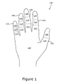
FIG. 1 is a schematic plan view of a palm-up human hand;
FIG. 2 a is a side elevational view of a first embodiment of the control device of the invention;
FIGS. 2 b, 2 c, and 2 d are three different cross-sectional views of the control device of FIG. 2 a;
FIG. 3 is a palm-side perspective view of the hand-held control device of FIG. 2 a with a user's hand closed around the control device;
FIG. 4 is a rear elevational view of an alternate embodiment of the control device of FIG. 2 a;
FIGS. 5 a and 5 b are schematic block diagrams showing, respectively, hard-wired and wireless modes of operation of the control device of FIG. 2 a;
FIG. 6 a is a palm-side perspective view of the control device of FIG. 2 a in position in a user's open hand but unsecured;
FIG. 6 b is a palm-side perspective view of the control device of FIG. 2 a in position in a user's open hand but secured by an elastic band; and
FIG. 6 c is a back side perspective view of the control device of FIG. 6 a.
FIG. 7 is a front side perspective view of the control device of FIG. 2 a.
DETAILED DESCRIPTION OF THE PREFERRED EMBODIMENT
Generally speaking this invention relates to a small, substantially symmetrical, hand-held control device adapted for interchangeable use in either the right or left hand of a user. The control device may be provided in a number of different configurations.
Referring first to FIG. 1, there is shown a top plan schematic view 100 of the front side of a human hand identifying the jointed segments of the fingers including thumb 102, index finger 104, middle finger 106, ring finger 108, and little finger 110. Each finger 104, 106, 108, 110 has three bones (i.e., phalanges) defining first, second, and third phalangeal regions 112, 114, and 116, respectively. As used herein, first phalangeal region refers to the phalange closest to and interconnected to a respective metacarpal bone of the hand while the third phalangeal region 116 is that region at the tip of the finger 104, 106, 108, 110, and thumb 102. Thumb 102 has only two phalanges thereby defining only phalangeal regions 114, 116 therein. Hand 100 has a palm region 118 which overlies the five metacarpal bines, not shown, of hand 100.
Referring now also to FIGS. 2 a and 3, there are shown side, elevational and an in situ, perspective view, respectively, of a first embodiment of the control device of the invention, generally at reference number 200 (FIG. 2 a). Unlike any control devices of the prior art, control device 200 is designed for placement adjacent the palm region 118 of a hand 100 where it may readily be held in place by at least one finger 104, 106, 108, 110 encircling and thereby securing control device 200. Alternately, control device 200 may be captured and secured by applying pressure between thumb 102 and at least one other finger 104, 106, 108, 110 or palm region 118. Unlike any prior art pointing devices, the unique shape of housing 202 of control device 200 allows the encirclement thereof by only one finger 104, 106, 108, 110 to secure the control device 200 in an operable position. This unique shape and the position of control device 200 in the user's hand allows the user to utilize the tips of any or all fingers 104, 106, 108, 110 to perform tasks unrelated to the control device 200, for example, typing.
Control device 200 has a substantially symmetrical shape on its vertical axis and may, therefore, be interchangeably used in either the right hand, (mirror of FIG. 3), or the left hand, (FIG. 3), of a user.
The shape of housing 202 of control device 200 may best be described as a shape conforming naturally, snuggly, and comfortably to a cavity created in a user's hand 100 by the natural and normal closing (i.e., curling the fingers of the hand so as to grip an object). Another way to describe the shape of housing 202 is an ergonomically contoured, “pistol grip”, housing. Referring now also to FIGS. 2 b, 2 c and 2 d, there are shown three examples of possible cross-sectional views of housing 202 taken along line 210 indicated by arrows A-A. It may readily be seen that the sides 212 of housing 202 are generally curvilinear. Many variations of the cross-sectional shape of housing 202 as exemplified in FIGS. 2 b, 2 c, and 2 d are possible. While in the preferred embodiment of the control device 200 of the invention sides 212 are symmetrical and convex, it is possible to create alternate embodiments having asymmetrical sides, concave sides, or other more complex curvilinear shapes. The invention is not, therefore, considered limited to one of the specific shapes chosen for purposes of disclosure.
Housing 202 has an upper region 204 and a actuation device 206 (i.e., a trackball, joystick, touch pad, or other device adapted to translate the movement of thumb 102 into an electrical signal representative of the movement of thumb 102). Such activation devices are known to those of skill in the art and are not further described herein. Actuation device 206 is shown, for purposes of disclosure, as a track ball in FIGS. 2 and 3 but it will be recognized that other actuation devices, either known or yet to be invented, may readily be substituted therefore. As the actual actuation device forms no part of the instant invention, the invention is not considered limited to the particular activation devices chosen for purposes of disclosure but is seen to encompass any actuation device capable of translating either movement or position of a user's thumb 102 to an electrical signal.
Switches 208 a, 208 b, 208 c and disposed on a front region (i.e., a region substantially diametrically opposed to the location of actuation device 206) of housing 202 and are adapted for actuation by a respective first, second, or third phalangeal region 112, 114, 116, respectively, of a respective one of fingers 104, 106, 108, 110. It will re recognized that control device 200 may have no switches 208 or that one, two, three, or more switches 208 n may be present. However, for typical computer mouse applications, a minimum of two switches are assumed to be present. Therefore, the inventive concept is not limited to a particular number of switches 208 n but rather includes embodiments having no switches to embodiments having one or more switches 208 n.
Because of the unique shape of housing 202 and the variance of user's hands as well a personal preferences, housing 202 may occupy a wide variety of positions in a user's hand 100. Depending upon where a user positions housing 202 in his or her hand 100, switches 208 a, 208 b, 208 c . . . 208 n may be actuated by whichever of first, second or third phalangeal regions 112, 114, 116, respectively, which happen to fall over respective ones of switches 208 a, 208 b, 208 c in a particular position of housing 202 in the user's hand 100. Regardless of which one of first, second, or third phalangeal regions 112, 114, 116 actually activate respective ones of switches 208 a, 208 b, 208 c, activation is caused by the natural motion of fingers 104, 106, 108, 110 contracting from an extended position such as that shown in FIG. 1 to a closed position such as shown in FIG. 3. The term “natural motion” of the fingers 104, 106, 108, 110 as used herein may be thought of as a squeezing or contracting motion as the fingers move from an extended to an encircling position. It will be recognized that depending upon the exact placement of housing 202 in palm region 118 of hand 100, different ones of switches 208 a, 208 b, 208 c may each be actuated by a different one of first, second, and third phalangeal regions 112, 114, 116 of corresponding ones of fingers 104, 106, 108, 110.
In the preferred embodiment, switches 208 a, 208 b, 208 c are implemented as discrete switch devices enclosed in housing 202. It will be recognized that switches 208 a, 208 b, 208 c could alternately be implemented as a single switch device, not shown, having multiple switch elements, not shown, included as a part thereof. Such a switch assembly could be mounted either within housing 202 or on an outside surface thereof and could include any practical number of switch elements. While in the preferred embodiment, switches 208 a, 208 b, 208 c are typically momentary contact switches, other switch types, for example, toggled on-off switches could also be used as required to meet a particular operating circumstance or environment.
In other embodiments of control device 200, an actuation mechanism 206 may incorporate one or more switch functions. One or more of these switch functions may replace, parallel, or supplement one or more of the functions normally performed by switches 208 a, 208 b, 208 c.
Referring now to FIG. 4, there is shown a rear elevational view of an alternate embodiment of control device 200, generally at 200′. Housing 202 has a scroll wheel 218 disposed in an upper region thereof adjacent actuating device 206. Scroll wheel 218 is representative of any device capable of controlling scrolling action in a manner consistent with a scroll wheel on a mouse, not shown, or any other pointing device of the prior art. Scroll wheel 218 may incorporate a switch, not shown, to replace, parallel, or supplement one of switches 208 a, 208 b, 208 c, . . . 208 n (FIG. 2 a). In still other embodiments, the scroll wheel switch may be disposed to perform a function not necessarily associated with one of switches 208 a, 208 b, 208 c. The inclusion of scroll wheel 218 or the like provides additional functionality to control device 200FIG. 4 without limiting any of the functionality and ease of use of control device 200 (FIG. 2 a). Scroll wheel 218 is intended to represent any scroll control device and the invention is not considered limited to the scroll wheel chosen for purposes of disclosure. Rather, the invention is seen to cover any functionally equivalent replacement.
As described hereinabove, actuation device 206 is typically manipulated by the user's thumb 102. Circuitry (not shown) within housing 202 is adapted to receive input signals from actuation device 206 and switches 208 a, 208 b, 208 c . . . 208 n and provide a standardized output signal compatible with the output signal of a standard mouse or other similar pointing device.
Communications between the circuitry and the computer or similar device to which control device 200 is providing signals may be by either a hard-wired connection or by a wireless interconnection. The preferred wireless interconnection is typically a radio frequency RF signal. However, infrared (IR) or other known wireless interconnection strategies could be substituted for an RF or IR link. Both types of electrical communications interfaces are well known in the art and form no part of the present invention. A “tail” 214 emerging from a lower distal point of housing 202 may be a hard wire cable leading to a remote computer (not shown), or, in alternate embodiments, may be an antenna for transmitting signals to a receiver. In the wireless embodiment of the control device, it will be recognized that power must be supplied for both the internal transmitter (not shown) and for the actuation device/switch interface circuitry as well. Power may be provided by a battery, not shown, which, of course, could be a disposable replacement battery, a removable rechargeable battery, or a rechargeable battery with a suitable connector, not shown, provided for applying recharging power to the internal, rechargeable battery. In hard wired embodiments, all necessary power may be supplied by the computer or other apparatus to which the control device 200 is attached.
The two possible communications strategies are illustrated in FIGS. 5 a and 5 b, respectively. It will also be recognized that other wireless interconnection strategies are available and could be used instead of an RF communications. Infrared (IR) is one such alternate communications link. The advantage of a RF communications link over an IR link is that there is no need to maintain an unblocked line of sight to the receptor (i.e., antenna) such as is required when using an IR link.
In operation, the inventive control device 200 rests in a user's hand 100 with switches 208 a, 208 b, 208 c positioned adjacent the index and subsequent fingers 104, 106, 108, 110. By positioning control device 200 in this way, relatively small movements of the fingers 104, 106, 108, 110 are required to activate their respective switches 208 a, 208 b, 208 c. It will be noted that the tips of fingers 104, 106, 108, 110 remain relatively unencumbered if desired and, consequently, are available for other operations or functions in addition to actuating control device 200 switches 208 a, 208 b, 208 c. In addition, housing 202 is sized and shaped so as to provide an ergonomically proper relationship between; actuating device 206 and the user's thumb 102; and the user's fingers 104, 106, 108, 110 and corresponding switches 208 a, 208 b, 208 c as shown in FIG. 3.
Referring now to FIGS. 6 a, 6 b, and 6 c, there are shown perspective front open with control device 200 unsecured (FIG. 6 a), perspective front open with control device 200 secured (FIG. 6 b), back perspective views with control device 200 secured (FIG. 6 c), respectively, of the control device 200 secured to the user's hand 100 using band 216. By securing control device 200 to a user's hand 100 using band 216 or any other suitable method, the user may utilize thumb 102 and fingers 104, 106, 108, 110 for other operations such as typing on the computer keyboard (not shown) or other similar tasks. Band 216 may be a continuous elastic band or bands. In alternate embodiments, straps having hook and loop fasteners (e.g., Velcro®) or other similar fasteners could also be used.
FIG. 7 shows a front view of the housing 202 with the three switches 208 a, 208 b and 208 c. In alternate embodiments, switches could range from none to any number controllable by the users fingers and hand.
Since other modifications and changes varied to fit a particular operating requirements and environment will be apparent to those skilled in the art, the invention is not considered limited to the example chosen for purposes of disclosure, and covers all changes and modifications which do not constitute a departure from the true spirit and scope of the invention.
Having thus described the invention, what is desired to be protected by Letters Patent is presented in the subsequent appended claims.

Claims (19)

1. A symmetrical, hand-held computer control device for interchangeable use in either a right hand or a left hand of a user, comprising:
a) an elongated housing adapted and configured to fit snugly within a cavity created by the natural and normal closure of the fingers of a user's hand, said housing being formed fit interchangeably into a user's right or left hand; said housing being adapted for retention in said user's right or left hand between a phalangeal region of at least one finger of said user's right or left hand and a palm region thereof, thereby freeing portions of said fingers beyond said phalangeal regions for tasks unrelated to said control device;
b) an actuating mechanism disposed in an upper region of said housing and adapted and configured for interaction with the thumb of said right or left hand of said user, and adapted for generating an actuation signal representative of at least one of a position, and a movement of said thumb;
c) circuitry disposed within said housing and operatively connected to said actuating element and adapted to receive at least said actuating signal and to generate an output signal representative of at least said actuating signal; and
d) means for communicating operatively connected to said circuitry and adapted to communicate said output signal to an external device.
2. The symmetrical, hand-held computer control device for interchangeable use in either a right hand or a left hand of a user as recited in claim 1, wherein said actuation device comprises at least one of the devices: a trackball, a joy stick, a touch pad, a switch, and another actuating device.
3. The symmetrical, hand-held computer control device for interchangeable use in either a right hand or a left hand of a user as recited in claim 2, further comprising
e) at least one switch disposed in said housing and adapted for manipulative interaction with said a metacarpal region of a finger of said right or left hand of said user, said at least one switch producing a switch signal representative of the state of said at least one switch, and wherein said circuitry further comprises means for receiving said switch signal and generating an output signal representative of at least said actuation signal and said switch signal.
4. The symmetrical, hand-held computer control device for interchangeable use in either a right hand or a left hand of a user as recited in claim 3, wherein said at least one switch is adapted and configured for switchable interaction with a phalangeal region of a finger of said user's right or left hand.
5. The symmetrical, hand-held computer control device for interchangeable use in either a right hand or a left hand of a user as recited in claim 3, wherein said at least one switch comprises one of the switch configurations: one switch, two switches, three switches, four switches, and more than four switches, adapted and configured for switchable interaction with a phalangeal region of a finger of said right or left hand of said user.
6. The symmetrical, hand-held computer control device for interchangeable use in either a right hand or a left hand of a user as recited in claim 3, wherein said at least one switch comprise at least one discrete switch element.
7. The symmetrical, hand-held computer control device for interchangeable use in either a right hand or a left hand of a user as recited in claim 3, wherein said at least one switch comprise a switch assembly comprising at least two discrete switch elements.
8. The symmetrical, hand-held computer control device for interchangeable use in either a right hand or a left hand of a user as recited in claim 2, wherein said means for communicating comprises one of the connection methods: a hard-wired connection, and a wireless connection to said external device.
9. The symmetrical, hand-held computer control device for interchangeable use in either a right hand or a left hand of a user as recited in claim 2, further comprising:
f) a wireless transmitter comprising at least one of: a radio frequency (RF) transmitter, and an infrared transmitter, either adapted to transmit said output signal.
10. The symmetrical, hand-held computer control device for interchangeable use in either a right hand or a left hand of a user as recited in claim 2, further comprising:
f) optional means for securing said hand-held computer control device to said right or left hand of said user.
11. The symmetrical, hand-held computer control device for interchangeable use in either a right hand or a left hand of a user as recited in claim 10, wherein said optional means for securing said hand-help control device comprises at least one of the devices: an elastic band, and a strap having hook and loop fasteners.
12. The symmetrical, hand-held computer control device for interchangeable use in either a right hand or a left hand of a user as recited in claim 2, further comprising:
e) a scrolling mechanism disposed proximate an upper region of said housing and adapted for interaction with a thumb of a user's right or left hand and generating a scrolling signal representative of a position thereof, and wherein said circuitry further comprises means for receiving said scrolling signal and generating an output signal representative of at least said actuation signal and said scrolling signal.
13. The symmetrical, hand-held computer control device for interchangeable use in either a right hand or a left hand of a user as recited in claim 12, wherein said scrolling mechanism comprises a scroll wheel.
14. The symmetrical, hand-held computer control device for interchangeable use in either a right hand or a left hand of a user as recited in claim 13, wherein scroll wheel comprises a switch.
15. The symmetrical, hand-held computer control device for interchangeable use in either a right hand or a left hand of a user as recited in claim 12, further comprising:
f) at least one switch disposed in said housing and adapted for manipulative interaction with said a metacarpal region of a finger of said right or left hand of said user, said at least one switch producing a switch signal representative of the state of said at least one switch, and wherein said circuitry further comprises means for receiving said switch signal and generating an output signal representative of at least said actuation signal, said scrolling signal and said switch signal.
16. The symmetrical, hand-held computer control device for interchangeable use in either a right hand or a left hand of a user as recited in claim 15, wherein said at least one switch is adapted and configured for switchable interaction with a phalangeal region of a finger of said user's right or left hand.
17. The symmetrical, hand-held computer control device for interchangeable use in either a right hand or a left hand of a user as recited in claim 15, wherein said at least one switch comprises three switches one of the switch configurations: one switch, two switches, three switches, four switches, and more than four switches, adapted and configured for switchable interaction with a phalangeal region of a finger of said right or left hand of said user.
18. The symmetrical, hand-held computer control device for interchangeable use in either a right hand or a left hand of a user as recited in claim 15, wherein said at least one switch comprise at least one discrete switch element.
19. The symmetrical, hand-held computer control device for interchangeable use in either a right hand or a left hand of a user as recited in claim 15, wherein said at least one switch comprises a switch assembly comprising at least two discrete switch elements.
US10/954,071 2001-11-09 2004-09-29 Hand-held computer control device Expired - Fee Related US7379052B1 (en)

Priority Applications (1)

Application Number Priority Date Filing Date Title
US10/954,071 US7379052B1 (en) 2001-11-09 2004-09-29 Hand-held computer control device

Applications Claiming Priority (3)

Application Number Priority Date Filing Date Title
US09/986,591 US6816151B2 (en) 2001-11-09 2001-11-09 Hand-held trackball computer pointing device
PCT/US2003/013403 WO2004107309A1 (en) 2001-11-09 2003-05-12 Hand-held trackball computer pointing device
US10/954,071 US7379052B1 (en) 2001-11-09 2004-09-29 Hand-held computer control device

Related Parent Applications (1)

Application Number Title Priority Date Filing Date
US09/986,591 Continuation-In-Part US6816151B2 (en) 2001-11-09 2001-11-09 Hand-held trackball computer pointing device

Publications (1)

Publication Number Publication Date
US7379052B1 true US7379052B1 (en) 2008-05-27

Family

ID=34118075

Family Applications (3)

Application Number Title Priority Date Filing Date
US09/986,591 Ceased US6816151B2 (en) 2001-11-09 2001-11-09 Hand-held trackball computer pointing device
US10/954,071 Expired - Fee Related US7379052B1 (en) 2001-11-09 2004-09-29 Hand-held computer control device
US11/594,722 Expired - Lifetime USRE40698E1 (en) 2001-11-09 2006-11-08 Hand-held trackball computer pointing device

Family Applications Before (1)

Application Number Title Priority Date Filing Date
US09/986,591 Ceased US6816151B2 (en) 2001-11-09 2001-11-09 Hand-held trackball computer pointing device

Family Applications After (1)

Application Number Title Priority Date Filing Date
US11/594,722 Expired - Lifetime USRE40698E1 (en) 2001-11-09 2006-11-08 Hand-held trackball computer pointing device

Country Status (3)

Country Link
US (3) US6816151B2 (en)
AU (1) AU2003234299A1 (en)
WO (1) WO2004107309A1 (en)

Cited By (11)

* Cited by examiner, † Cited by third party
Publication number Priority date Publication date Assignee Title
US20050134570A1 (en) * 2003-12-23 2005-06-23 Andrew Strawn Personalised phone structure
US20070279380A1 (en) * 2006-05-31 2007-12-06 Bruno Rafael Murillo Computer input device
US20080007753A1 (en) * 2006-07-06 2008-01-10 Mark Van Regenmorter User interface for a multi-function peripheral device
US20080136778A1 (en) * 2006-12-05 2008-06-12 Eli Hursh Mouse device for a computer
US20090021481A1 (en) * 2007-07-16 2009-01-22 Walter Urbach Hand integrated mouse platform
US20100201625A1 (en) * 2007-07-16 2010-08-12 Walter Urbach Wearable Computer Mouse And Electronic Device Controller
US20120050168A1 (en) * 2010-08-24 2012-03-01 Hon Hai Precision Industry Co., Ltd. Handheld input device
US20120085870A1 (en) * 2010-10-07 2012-04-12 Bae Systems Plc Vehicle armrest
US20120297339A1 (en) * 2011-01-27 2012-11-22 Kyocera Corporation Electronic device, control method, and storage medium storing control program
US9007302B1 (en) 2011-11-11 2015-04-14 Benjamin D. Bandt-Horn Device and user interface for visualizing, navigating, and manipulating hierarchically structured information on host electronic devices
US10895914B2 (en) 2010-10-22 2021-01-19 Joshua Michael Young Methods, devices, and methods for creating control signals

Families Citing this family (52)

* Cited by examiner, † Cited by third party
Publication number Priority date Publication date Assignee Title
US7749089B1 (en) 1999-02-26 2010-07-06 Creative Kingdoms, Llc Multi-media interactive play system
US7445550B2 (en) 2000-02-22 2008-11-04 Creative Kingdoms, Llc Magical wand and interactive play experience
US7878905B2 (en) 2000-02-22 2011-02-01 Creative Kingdoms, Llc Multi-layered interactive play experience
US6761637B2 (en) 2000-02-22 2004-07-13 Creative Kingdoms, Llc Method of game play using RFID tracking device
US7066781B2 (en) 2000-10-20 2006-06-27 Denise Chapman Weston Children's toy with wireless tag/transponder
US7692667B2 (en) * 2001-08-17 2010-04-06 Palm, Inc. Handheld computer having moveable segments that are interactive with an integrated display
US20030034987A1 (en) * 2001-08-17 2003-02-20 William Webb Handheld computer having moveable segments that can be adjusted to affect a size of the handheld computer
US20030076296A1 (en) * 2001-10-22 2003-04-24 Kolybaba Derek J. Computer mouse
US7176882B2 (en) * 2001-11-12 2007-02-13 Ken Alvin Jenssen Hand held control device with dual mode joystick for pointing and scrolling
US20030142069A1 (en) * 2002-01-25 2003-07-31 Gatto Frank P. Hand-held ergonomic computer interface device
US20070066396A1 (en) 2002-04-05 2007-03-22 Denise Chapman Weston Retail methods for providing an interactive product to a consumer
US6967566B2 (en) 2002-04-05 2005-11-22 Creative Kingdoms, Llc Live-action interactive adventure game
US7674184B2 (en) 2002-08-01 2010-03-09 Creative Kingdoms, Llc Interactive water attraction and quest game
US9446319B2 (en) 2003-03-25 2016-09-20 Mq Gaming, Llc Interactive gaming toy
US20050151725A1 (en) * 2003-12-30 2005-07-14 Jennings Christopher P. User interface device
US20050190155A1 (en) * 2004-03-01 2005-09-01 Pollenz Adam S. Computer mouse carried on the palm of the hand
JP4366246B2 (en) * 2004-05-26 2009-11-18 パイオニア株式会社 Information input device
JP5080273B2 (en) 2005-01-07 2012-11-21 クアルコム,インコーポレイテッド Tilt sensor based on optical flow
DE102005016147B4 (en) * 2005-04-07 2007-11-08 Bury Sp.Z.O.O remote control
WO2006124935A2 (en) * 2005-05-17 2006-11-23 Gesturetek, Inc. Orientation-sensitive signal output
US8313379B2 (en) 2005-08-22 2012-11-20 Nintendo Co., Ltd. Video game system with wireless modular handheld controller
US7927216B2 (en) 2005-09-15 2011-04-19 Nintendo Co., Ltd. Video game system with wireless modular handheld controller
JP4805633B2 (en) 2005-08-22 2011-11-02 任天堂株式会社 Game operation device
US7942745B2 (en) 2005-08-22 2011-05-17 Nintendo Co., Ltd. Game operating device
US8870655B2 (en) 2005-08-24 2014-10-28 Nintendo Co., Ltd. Wireless game controllers
JP4262726B2 (en) 2005-08-24 2009-05-13 任天堂株式会社 Game controller and game system
US8308563B2 (en) 2005-08-30 2012-11-13 Nintendo Co., Ltd. Game system and storage medium having game program stored thereon
US8157651B2 (en) 2005-09-12 2012-04-17 Nintendo Co., Ltd. Information processing program
JP4151982B2 (en) 2006-03-10 2008-09-17 任天堂株式会社 Motion discrimination device and motion discrimination program
JP4989105B2 (en) * 2006-05-09 2012-08-01 任天堂株式会社 Game controller
US7626572B2 (en) * 2006-06-15 2009-12-01 Microsoft Corporation Soap mobile electronic human interface device
US20080201508A1 (en) * 2007-02-20 2008-08-21 Dan Gavish Method And Apparatus For an Enhanced Computer Peripheral Device
JP5224832B2 (en) * 2008-01-21 2013-07-03 任天堂株式会社 Information processing program and information processing apparatus
US8754853B2 (en) 2010-09-29 2014-06-17 The United States Of America As Represented By The Secretary Of The Navy Hand-interface for weapon station
CZ306185B6 (en) * 2013-08-15 2016-09-14 Linet, Spol. S R. O. Bed
US9715286B2 (en) 2014-01-28 2017-07-25 Solid Art Labs, Inc. Hand-controllable signal-generating devices and systems
US9785256B2 (en) * 2015-02-16 2017-10-10 Ming Xia Ergonomic computer mouse with handheld and ambidextrous body design
DE102015006109A1 (en) 2015-05-11 2016-11-17 Cyrus Zahedy Alphanumeric one-hand keyboard
CN105854291B (en) * 2016-06-03 2023-12-26 歌尔科技有限公司 Game control device and game equipment
US11625898B2 (en) 2016-10-11 2023-04-11 Valve Corporation Holding and releasing virtual objects
US10307669B2 (en) * 2016-10-11 2019-06-04 Valve Corporation Electronic controller with finger sensing and an adjustable hand retainer
US10888773B2 (en) 2016-10-11 2021-01-12 Valve Corporation Force sensing resistor (FSR) with polyimide substrate, systems, and methods thereof
US11185763B2 (en) 2016-10-11 2021-11-30 Valve Corporation Holding and releasing virtual objects
US10691233B2 (en) 2016-10-11 2020-06-23 Valve Corporation Sensor fusion algorithms for a handheld controller that includes a force sensing resistor (FSR)
US10898797B2 (en) * 2016-10-11 2021-01-26 Valve Corporation Electronic controller with finger sensing and an adjustable hand retainer
US10987573B2 (en) 2016-10-11 2021-04-27 Valve Corporation Virtual reality hand gesture generation
US10391400B1 (en) 2016-10-11 2019-08-27 Valve Corporation Electronic controller with hand retainer and finger motion sensing
USD860202S1 (en) * 2017-04-24 2019-09-17 Tactual Labs Co. Handheld controller
US10874939B2 (en) 2017-06-16 2020-12-29 Valve Corporation Electronic controller with finger motion sensing
WO2019113243A1 (en) 2017-12-07 2019-06-13 Valve Corporation Electronic controller with finger sensing and an adjustable hand retainer
US11273367B1 (en) * 2019-09-24 2022-03-15 Wayne Hughes Beckett Non-CRT pointing device
US11504615B1 (en) * 2021-05-18 2022-11-22 Valve Corporation Electronic controller with linear hand strap adjuster

Citations (15)

* Cited by examiner, † Cited by third party
Publication number Priority date Publication date Assignee Title
US5267181A (en) * 1989-11-03 1993-11-30 Handykey Corporation Cybernetic interface for a computer that uses a hand held chord keyboard
US5296871A (en) * 1992-07-27 1994-03-22 Paley W Bradford Three-dimensional mouse with tactile feedback
US5512892A (en) * 1994-02-25 1996-04-30 International Business Machines Corporation Hand held control device
US5668574A (en) * 1995-06-26 1997-09-16 Chung-Chin Chen Palm-top wireless trackball
US5724106A (en) * 1995-07-17 1998-03-03 Gateway 2000, Inc. Hand held remote control device with trigger button
US5760766A (en) * 1993-03-29 1998-06-02 International Business Machines Corp. Pointing device with relocatable cable
US5805256A (en) * 1995-02-27 1998-09-08 Miller; William Remote control with a thumbswitch for controlling equipment that handles video or audio signals
US5894303A (en) * 1995-03-14 1999-04-13 Barr; Ann E. Computer mouse and shell therefore
US5982356A (en) * 1997-10-15 1999-11-09 Akiyama; Robert Ergonomic computer cursor control apparatus and mount
USD430161S (en) * 2000-01-19 2000-08-29 Alexander Hovsepian Hand supported and controlled mouse
US6184862B1 (en) * 1996-07-08 2001-02-06 Thomas Leiper Apparatus for audio dictation and navigation of electronic images and documents
US20010035856A1 (en) * 2000-05-08 2001-11-01 Myers Christopher S. Palm-held computer pointing devices
US6429854B1 (en) * 2000-06-28 2002-08-06 Mckown John W. Stealthy keyboard
USD464053S1 (en) * 2000-06-27 2002-10-08 Patrick Zicolello Input device
US6680728B1 (en) * 1999-08-23 2004-01-20 David Michael Lilenfeld Cursor control device for convenient and ergonomic hand-held or work-surface use

Family Cites Families (3)

* Cited by examiner, † Cited by third party
Publication number Priority date Publication date Assignee Title
WO1991007826A1 (en) * 1989-11-22 1991-05-30 Russell David C Computer control system
US5648798A (en) * 1995-02-13 1997-07-15 Hamling; Daniel T. Universal ergonomic computer mouse/trackball
US6222526B1 (en) * 1998-10-29 2001-04-24 Quentin J. Holmes Hand held ergonomic computer controller

Patent Citations (16)

* Cited by examiner, † Cited by third party
Publication number Priority date Publication date Assignee Title
US5267181A (en) * 1989-11-03 1993-11-30 Handykey Corporation Cybernetic interface for a computer that uses a hand held chord keyboard
US5296871A (en) * 1992-07-27 1994-03-22 Paley W Bradford Three-dimensional mouse with tactile feedback
US5506605A (en) * 1992-07-27 1996-04-09 Paley; W. Bradford Three-dimensional mouse with tactile feedback
US5760766A (en) * 1993-03-29 1998-06-02 International Business Machines Corp. Pointing device with relocatable cable
US5512892A (en) * 1994-02-25 1996-04-30 International Business Machines Corporation Hand held control device
US5805256A (en) * 1995-02-27 1998-09-08 Miller; William Remote control with a thumbswitch for controlling equipment that handles video or audio signals
US5894303A (en) * 1995-03-14 1999-04-13 Barr; Ann E. Computer mouse and shell therefore
US5668574A (en) * 1995-06-26 1997-09-16 Chung-Chin Chen Palm-top wireless trackball
US5724106A (en) * 1995-07-17 1998-03-03 Gateway 2000, Inc. Hand held remote control device with trigger button
US6184862B1 (en) * 1996-07-08 2001-02-06 Thomas Leiper Apparatus for audio dictation and navigation of electronic images and documents
US5982356A (en) * 1997-10-15 1999-11-09 Akiyama; Robert Ergonomic computer cursor control apparatus and mount
US6680728B1 (en) * 1999-08-23 2004-01-20 David Michael Lilenfeld Cursor control device for convenient and ergonomic hand-held or work-surface use
USD430161S (en) * 2000-01-19 2000-08-29 Alexander Hovsepian Hand supported and controlled mouse
US20010035856A1 (en) * 2000-05-08 2001-11-01 Myers Christopher S. Palm-held computer pointing devices
USD464053S1 (en) * 2000-06-27 2002-10-08 Patrick Zicolello Input device
US6429854B1 (en) * 2000-06-28 2002-08-06 Mckown John W. Stealthy keyboard

Cited By (16)

* Cited by examiner, † Cited by third party
Publication number Priority date Publication date Assignee Title
US7573460B2 (en) * 2003-12-23 2009-08-11 Nokia Corporation Personalised phone structure
US20050134570A1 (en) * 2003-12-23 2005-06-23 Andrew Strawn Personalised phone structure
US20070279380A1 (en) * 2006-05-31 2007-12-06 Bruno Rafael Murillo Computer input device
US20080007753A1 (en) * 2006-07-06 2008-01-10 Mark Van Regenmorter User interface for a multi-function peripheral device
US20080136778A1 (en) * 2006-12-05 2008-06-12 Eli Hursh Mouse device for a computer
US8373653B2 (en) 2007-07-16 2013-02-12 Walter Urbach III Trust Hand integrated operations platform
US20090021481A1 (en) * 2007-07-16 2009-01-22 Walter Urbach Hand integrated mouse platform
US20100201625A1 (en) * 2007-07-16 2010-08-12 Walter Urbach Wearable Computer Mouse And Electronic Device Controller
US8514173B2 (en) 2007-07-16 2013-08-20 Norstar Asset Management, Inc. Hand integrated operations platform
US20120050168A1 (en) * 2010-08-24 2012-03-01 Hon Hai Precision Industry Co., Ltd. Handheld input device
US20120085870A1 (en) * 2010-10-07 2012-04-12 Bae Systems Plc Vehicle armrest
US9567065B2 (en) * 2010-10-07 2017-02-14 Bae Systems Plc Vehicle armrest
US10895914B2 (en) 2010-10-22 2021-01-19 Joshua Michael Young Methods, devices, and methods for creating control signals
US20120297339A1 (en) * 2011-01-27 2012-11-22 Kyocera Corporation Electronic device, control method, and storage medium storing control program
US9007302B1 (en) 2011-11-11 2015-04-14 Benjamin D. Bandt-Horn Device and user interface for visualizing, navigating, and manipulating hierarchically structured information on host electronic devices
US9829987B2 (en) 2011-11-11 2017-11-28 Benjamin D. Bandt-Horn Device and user interface for visualizing, navigating, and manipulating hierarchically structured information on host electronic devices

Also Published As

Publication number Publication date
WO2004107309A1 (en) 2004-12-09
AU2003234299A1 (en) 2005-01-21
US20030090465A1 (en) 2003-05-15
US6816151B2 (en) 2004-11-09
USRE40698E1 (en) 2009-04-14

Similar Documents

Publication Publication Date Title
US7379052B1 (en) Hand-held computer control device
US10874936B2 (en) Hand-held controller with pressure-sensing switch for virtual-reality systems
US6850224B2 (en) Wearable ergonomic computer mouse
US20020171625A1 (en) Pistol-grip trackball mouse
US20180161670A1 (en) Single-Handed Input Controller and Method
US6828958B2 (en) Ergonomic side grip computer mouse
AU2004303361B2 (en) Hand manipulated data apparatus for computers and video games
US4862165A (en) Ergonomically-shaped hand controller
US8681101B1 (en) Finger mounted input device
US20020163495A1 (en) Multi-functional ergonomic interface
US20050159850A1 (en) Shift knob computer operating device
US20040051694A1 (en) Portable device for inputting control signals to a peripheral unit, and use of such a device
US7176882B2 (en) Hand held control device with dual mode joystick for pointing and scrolling
JP2005524897A (en) Ergonomic computer pointing device
WO2003025734A1 (en) A portable unit for inputting signals to a peripheral unit, and use of such a unit
US8373653B2 (en) Hand integrated operations platform
JP2001236177A (en) Mouse
US20110074680A1 (en) Knee operated computer mouse
CN218075213U (en) Multifunctional control device for surgical robot
US20060176268A1 (en) Device for inputting control signals to a peripheral unit and a combination including such a device
RU2493580C1 (en) Information input device
TW200825845A (en) Finger-operated input device
KR200198987Y1 (en) Mouse having biomechanical structure
KR20080002046U (en) Joystick Shaped Ergonomics Mouse
WO2005017733A1 (en) Control device for providing position information

Legal Events

Date Code Title Description
AS Assignment

Owner name: INTEL CORPORATION, CALIFORNIA

Free format text: ASSIGNMENT OF ASSIGNORS INTEREST;ASSIGNORS:PIEDA, RUEL B.;LIBAY, CARMELITO M.;BUOT, JOAN REY V.;REEL/FRAME:015589/0441

Effective date: 20041209

STCF Information on status: patent grant

Free format text: PATENTED CASE

REMI Maintenance fee reminder mailed
FPAY Fee payment

Year of fee payment: 4

SULP Surcharge for late payment
FEPP Fee payment procedure

Free format text: PATENT HOLDER CLAIMS MICRO ENTITY STATUS, ENTITY STATUS SET TO MICRO (ORIGINAL EVENT CODE: STOM); ENTITY STATUS OF PATENT OWNER: MICROENTITY

REMI Maintenance fee reminder mailed
FPAY Fee payment

Year of fee payment: 8

SULP Surcharge for late payment
FEPP Fee payment procedure

Free format text: MAINTENANCE FEE REMINDER MAILED (ORIGINAL EVENT CODE: REM.); ENTITY STATUS OF PATENT OWNER: MICROENTITY

LAPS Lapse for failure to pay maintenance fees

Free format text: PATENT EXPIRED FOR FAILURE TO PAY MAINTENANCE FEES (ORIGINAL EVENT CODE: EXP.); ENTITY STATUS OF PATENT OWNER: MICROENTITY

STCH Information on status: patent discontinuation

Free format text: PATENT EXPIRED DUE TO NONPAYMENT OF MAINTENANCE FEES UNDER 37 CFR 1.362