US7292577B1 - End-to-end preservation of VLAN priority in connection-oriented networks - Google Patents
End-to-end preservation of VLAN priority in connection-oriented networks Download PDFInfo
- Publication number
- US7292577B1 US7292577B1 US09/957,311 US95731101A US7292577B1 US 7292577 B1 US7292577 B1 US 7292577B1 US 95731101 A US95731101 A US 95731101A US 7292577 B1 US7292577 B1 US 7292577B1
- Authority
- US
- United States
- Prior art keywords
- vlan
- priorities
- source
- connection
- traffic
- Prior art date
- Legal status (The legal status is an assumption and is not a legal conclusion. Google has not performed a legal analysis and makes no representation as to the accuracy of the status listed.)
- Active, expires
Links
Images


Classifications
-
- H—ELECTRICITY
- H04—ELECTRIC COMMUNICATION TECHNIQUE
- H04L—TRANSMISSION OF DIGITAL INFORMATION, e.g. TELEGRAPHIC COMMUNICATION
- H04L12/00—Data switching networks
- H04L12/28—Data switching networks characterised by path configuration, e.g. LAN [Local Area Networks] or WAN [Wide Area Networks]
- H04L12/46—Interconnection of networks
- H04L12/4641—Virtual LANs, VLANs, e.g. virtual private networks [VPN]
-
- H—ELECTRICITY
- H04—ELECTRIC COMMUNICATION TECHNIQUE
- H04L—TRANSMISSION OF DIGITAL INFORMATION, e.g. TELEGRAPHIC COMMUNICATION
- H04L45/00—Routing or path finding of packets in data switching networks
- H04L45/302—Route determination based on requested QoS
- H04L45/306—Route determination based on the nature of the carried application
Definitions
- the present invention relates generally to the field of network communication. More specifically, the present invention relates to a method and a system for maintaining priority of virtual local area network (VLAN) traffic across connection-oriented networks.
- VLAN virtual local area network
- a VLAN is a local area network that maps workstations or nodes on a basis other than geographic location (for example, by department, type of user, or primary application). VLANs are used to regulate the access of information among nodes that reside in different multiple networks. Although these networks are physically connected, logically they are separate.
- FIG. 1 illustrates an example of prior art VLANs.
- Each of the switches 106 , 107 , 108 performs the transfer of frames from one Ethernet segment to another Ethernet segment.
- the Ethernet segment 101 includes nodes 105 and 110 .
- the Ethernet segment 102 includes nodes 115 and 120 .
- the Ethernet segment 103 includes nodes 125 and 130 .
- Each of the nodes in the Ethernet segments 101 , 102 , 103 may be a workstation such as a personal computer.
- VLAN traffic is generated by multiple different applications. Some of these applications are mission critical applications and demand higher priority of service than other applications. VLANs can be implemented in an Ethernet network by inserting a VLAN tag into an Ethernet frame. Originally, an Ethernet frame is defined to have a minimum frame size of 64 bytes and a maximum frame size of 1518 bytes. The maximum allowable frame size is extended by four (4) bytes to 1522 bytes to allow insertion of the VLAN tag.
- the last two bytes or 16 bits are used as follows: the first three (3) bits are used as a priority field to assign a priority level to the Ethernet frame, the next one (1) bit is used to indicate the presence of a routing information field (RIF), the last 12 bits are used as a VLAN identifier (VID) field that uniquely identifies the VLANs to which the Ethernet frame belongs. Each VLAN gets a unique network number or identifier (using the VID field).
- the nodes 105 and 115 may be configured to be in a first VLAN.
- the nodes 110 , 120 , 125 and 130 may be configured to be in a second VLAN.
- a node can belong to more than one VLAN.
- the node 115 (or node C) may be configured to be in both the first VLAN and the second VLAN.
- the nodes in the first VLAN and in the second VLAN may be connected to different Ethernet segments.
- a port on the switch 106 may receive frames from the first VLAN or from the second VLAN. The switch delivers the frames based on the VID in the VLAN tag of each packet.
- node 110 When the node 110 (or node B) sends a broadcast message, frames associated with the broadcast message are sent only to those nodes belonging to the second VLAN (i.e., nodes D, E and F), even though the frames may cross the switches 106 , 107 , and 108 .
- Each switch reads the incoming frames and, according to how the addressing (e.g., port assignment) of the network is defined, identifies each VLAN.
- the network 100 may be a connection-oriented network such as, for example, an Asynchronous Transfer Mode (ATM) network and Multi-Protocol Label Switching (MPLS) network.
- ATM Asynchronous Transfer Mode
- MPLS Multi-Protocol Label Switching
- There may be different type of services e.g., bandwidth, jitter, delay, etc.
- types of traffic e.g., voice, video, data, etc.
- the type of service is established at the time that the connection is made.
- the ATM Forum has defined four quality-of-service types of service that are architected to handle the different types of traffic. These types of service include Constant Bit Rate (CBR), Variable Bit Rate (VBR), Unspecified Bit Rate (UBR), Guaranteed Frame Rate (GFR), and Available Bit Rate (ABR).
- CBR Constant Bit Rate
- VBR Variable Bit Rate
- URR Unspecified Bit Rate
- GFR Guaranteed Frame Rate
- ABR Available Bit Rate
- CBR is a reserved bandwidth service.
- a contract is established between the network and the end station.
- the end station provides the network with parameters describing the traffic for that specific connection at call setup time.
- the network allocates resources that match the parameters.
- VBR is also a reserved bandwidth service.
- the network allocates resources to the end station at call setup time in response to the traffic parameters requested by the end station.
- a sustainable rate and a maximum burst size are established.
- the sustainable rate is the upper limit of the average rate, and the maximum burst rate limits the duration of cell transmission at peak rate.
- GFR provides a rate guarantee for application traffic across networks.
- UBR is a non-reserved bandwidth service.
- ABR is a mix of reserved and non-reserved bandwidth service.
- a connection polls the network and, based upon the feedback it receives, adjusts its transmission rate.
- the three bits priority field in the VLAN tag is used as a priority field to assign a priority level to the Ethernet frame.
- the quality of service of this connection may be CBR, VBR, GFR, UBR, or ABR.
- all Ethernet frames transmitted by the node 110 to the node 125 are transferred from the switch 106 to the switch 108 using the same connection having the same ATM quality of service.
- a connection is identified by its VPI/VCI.
- VPI is a virtual path identifier that identifies a path that an ATM cell will take.
- VCI is a virtual channel identifier that identifies a channel within the path that the ATM cell will take to reach its destination.
- Ethernet frames having higher priority are treated the same by the ATM network 100 as Ethernet frames having lower priority.
- VLAN virtual local area network
- VIPs VLAN identifications
- WAN connection-oriented wide area network
- Each VLAN supports multiple priorities.
- VCs Virtual connections are set up based using a combination of the VID and the mapping of the priorities to the service types.
- FIG. 1 is a network diagram illustrating VLANs.
- FIG. 2 is a table illustrating one example of how the eight possible priority values are assigned.
- FIG. 3 is a network diagram illustrating multiple virtual connections (VC) to accommodate different VLAN priority values.
- FIG. 4 is a table illustrating mapping of VLAN priorities to virtual connections (VC).
- FIG. 5 is a table illustrating translation of VLAN IDs in different LAN segments.
- FIG. 6 is a flow diagram illustrating one embodiment of a VLAN to virtual connection mapping process.
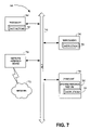
- FIG. 7 is an illustration of one embodiment of a digital processing system that can be used with one embodiment of the present invention.
- a method and a system for transmitting prioritized Virtual Local Area Network (VLAN) traffic across a connection-oriented network is disclosed.
- Supported VLAN priorities are mapped to appropriate virtual connections (VC) before the VLAN traffic enters the network. Traffic from each virtual connection is mapped into VLAN traffic when it exits the network.
- VC virtual connections
- the VLAN tag includes a three-bit priority field that allows for prioritization of VLAN traffic over the Ethernet LANs.
- the VLAN tag allows a device to establish up to eight priority values in identifying traffic for a specific VLAN. For example, when a frame is received, it is prioritized based on the VLAN it belongs to or based on the priority field it contains and placed in appropriate queue. The frames having the highest priority are emptied first from the queue. More important VLAN traffic (e.g., real time traffic) is given higher priority value than less important VLAN traffic (e.g., email).
- FIG. 2 is a table illustrating one example of how the eight possible priority values are assigned to VLAN traffic using the priority field in the VLAN tag.
- the VLAN traffic is transmitted across a connection-oriented network using one connection.
- the transmission priority of the VLAN traffic is thus dependent on the quality of service associated with that connection.
- Higher priority VLAN traffic is treated the same as lower priority VLAN traffic.
- multiple virtual connections are used to give the VLAN traffic different quality of service corresponding to the different VLAN priority values. For example, VLAN traffic having a highest priority value may be sent across a virtual connection (VC) set up with a constant bit rate (CBR) quality of service. VLAN traffic having a next highest priority value may be sent across a VC set up with a variable bit rate (VBR).
- VBR variable bit rate
- the multiple virtual connections allow the VLAN traffic to be treated with different quality of service corresponding to the different VLAN priority values.
- the frames are mapped into different classes of service based on the VLAN priority value.
- Each of these ATM connections is mapped to different classes of service. Note that the types of service offered by the connection-oriented network may not match exactly with the number of priority values defined in the VLAN. Thus, having multiple virtual connections enables the prioritized VLAN traffic to be transmitted across the network using different classes of service.
- FIG. 3 is a network diagram illustrating multiple virtual connections to transmit VLAN traffic with different priority values. Instead of having one virtual connection to transmit the VLAN traffic, multiple virtual connections 305 are used. For example, when the priority bits are set up such that there are four valid priorities, four virtual connections are set up. The VLAN traffic from the Ethernet network 310 is mapped into these virtual connections 305 when the VLAN traffic enters the network 300 .
- Switch 320 is referred to as a source end point
- switch 330 is referred to as a destination end point.
- the switch 320 When the switch 320 receives an Ethernet frame, the switch 320 looks at the VLAN tag (including the VID and the priority field) and maps the Ethernet frame to the appropriate virtual connection.
- the VLAN traffic may cross multiple switches (e.g., switches 320 , 325 , 330 ) before it arrives at the destination network 315 .
- switches 320 , 325 , 330 e.g., switches 320 , 325 , 330 .
- the VLAN traffic is then mapped by the switch 330 from the virtual connections to the Ethernet frame as defined by the network 315 .
- FIG. 4 is a table that illustrates mapping of VLAN priorities to virtual connections (VC).
- VLAN ID lists the different VLAN IDs for VLAN traffic entering a network.
- the column under the heading “Priority” lists the different priorities defined for these VLANs.
- the VLAN ID may be different in each Ethernet LAN segment even though the nodes may belong to the same VLAN.
- the second VLAN includes the nodes 110 , 120 , 125 and 130 .
- the VID for the node 110 may be different from the VID for the nodes 125 and 130 .
- the VID for the node 110 may be different from the VID for the node 120 .
- Each of the switches 106 , 107 , and 108 needs to be able to recognize that these nodes belong to the same VLAN.
- the switch 107 recognizes that the message is to be delivered to the node 120 even though the node 120 may have a VID of five (5).
- the switch 108 recognizes that the message is to be delivered to the nodes 125 and 130 even though the nodes 125 and 130 may have a VID of two (2).
- FIG. 5 is a table illustrating translation of VIDs in different Ethernet LAN segments. Depending on how the VID is allocated in each Ethernet LAN segment, the VID can be translated from one value to another value.
- the column under the heading “VLAN ID#1” lists the different VLAN IDs for VLAN traffic entering a network. In this example, there are two VLANs having the VLAN IDs of three (3) and eight (8) respectively.
- the column under the heading “Priority” is the same as described in FIG. 4 for the column under the heading “VLAN Priority”.
- the columns under the headings “VPI/VCI” and “Quality of Service” are the same as described in FIG. 4 .
- VLAN ID#2 lists the different VLAN IDs for VLAN traffic leaving the network. In this example, there are two VLANs having the VLAN IDs of five (5) and two (2) respectively. Note that the column under the second “priority” heading lists the same priority values as those listed in the column under the first “priority” heading.
- FIG. 6 is a flow diagram illustrating one embodiment of a VLAN to virtual connection mapping process.
- the process starts at block 605 from a source end point.
- the VID and the priorities supported by the VLAN having that VID are identified.
- the supported priorities are mapped to the different service types available in the connection-oriented network. For example, priority six (6) is mapped to CBR; priority five (5) is mapped to CBR; priority zero (0) is mapped to UBR, etc.
- VCs are set up corresponding to a service type. The number of VCs setup is based on the number of VID and priorities combination supported by the VLAN. For example, the table in FIG.
- each combination of the VID and one of the supported priorities is mapped to a virtual connection.
- the virtual connection is mapped to a type of service based on the mapping performed in block 615 .
- the process ends at block 630 .
- block 505 indicates that traffic received from the VC having the VPI/VCI of 11/105 corresponds to VLAN traffic having VID of two (2) and VLAN priority of 5.
- FIG. 7 is an illustration of one embodiment of a digital processing system that can be used with the present invention.
- the operations of the various methods of the present invention may be implemented by a processing unit 742 in a digital processing system 740 .
- the processing unit 742 is coupled with the bus 748 and executes sequences of computer program instructions 762 .
- the computer program instructions 762 may include instructions to perform the virtual connection mapping process illustrated in FIG. 6 .
- the instructions 762 may be stored in a memory which may be considered to be a machine-readable storage media 760 .
- the machine-readable storage media 760 may be used with a drive unit 754 coupled with the bus 748 .
- the instructions 762 may be loaded into main memory 746 coupled with the bus 748 .
- other memory devices such as, for example, read-only memory, a persistent storage memory, or any combination of these devices may also be used to store the instructions 762 .
- Execution of the sequences of instruction 762 causes the processing unit 742 to perform operations according to the present invention.
- the instructions 762 may be loaded into the main memory 746 from a storage device or from one or more other digital processing systems (e.g. a server computer system) over a network 770 using network interface device 758 .
- the instructions 762 may not be performed directly or they may not be directly executable by the processing unit 742 .
- the executions may be executed by causing the processing unit 742 to execute an interpreter that interprets the instructions 762 , or by causing the processing unit 742 to execute instructions which convert the received instructions 762 to instructions which can be directly executed by the processor.
- hard-wired circuitry may be used in place of or in combination with software instructions to implement the present invention.
- the present invention is not limited to any specific combination of hardware circuitry and software, nor to any particular source for the instructions executed by the digital processing system 740 .
Abstract
Description
Claims (16)
Priority Applications (1)
| Application Number | Priority Date | Filing Date | Title |
|---|---|---|---|
| US09/957,311 US7292577B1 (en) | 2001-09-19 | 2001-09-19 | End-to-end preservation of VLAN priority in connection-oriented networks |
Applications Claiming Priority (1)
| Application Number | Priority Date | Filing Date | Title |
|---|---|---|---|
| US09/957,311 US7292577B1 (en) | 2001-09-19 | 2001-09-19 | End-to-end preservation of VLAN priority in connection-oriented networks |
Publications (1)
| Publication Number | Publication Date |
|---|---|
| US7292577B1 true US7292577B1 (en) | 2007-11-06 |
Family
ID=38653448
Family Applications (1)
| Application Number | Title | Priority Date | Filing Date |
|---|---|---|---|
| US09/957,311 Active 2024-08-24 US7292577B1 (en) | 2001-09-19 | 2001-09-19 | End-to-end preservation of VLAN priority in connection-oriented networks |
Country Status (1)
| Country | Link |
|---|---|
| US (1) | US7292577B1 (en) |
Cited By (23)
| Publication number | Priority date | Publication date | Assignee | Title |
|---|---|---|---|---|
| US20050129024A1 (en) * | 2003-12-10 | 2005-06-16 | Alcatel | Providing VPLS-like service over native ATM networks |
| US20070230481A1 (en) * | 2006-03-31 | 2007-10-04 | Hiroki Ikeda | Passive optical network system for supporting virtual ethernet service and method for the same |
| US20070263660A1 (en) * | 2006-05-12 | 2007-11-15 | Fujitsu Limited | Packet transmission apparatus, packet forwarding method and packet transmission system |
| US20080133719A1 (en) * | 2006-11-30 | 2008-06-05 | Ofer Amitai | System and method of changing a network designation in response to data received from a device |
| US20090201847A1 (en) * | 2008-02-07 | 2009-08-13 | Gilat Satellite Networks, Ltd. | Real-Time Sessions Quality-Of-Service Over Reservation-Based Access |
| US20090279545A1 (en) * | 2006-09-15 | 2009-11-12 | Koninklijke Philips Electronics N.V. | Automatic packet tagging |
| US20100020820A1 (en) * | 2004-06-09 | 2010-01-28 | Lawrence Jones | Prioritized segmentation and reassembly methods and systems |
| WO2011160696A1 (en) * | 2010-06-25 | 2011-12-29 | Siemens Aktiengesellschaft | Prioritized transfer of data telegrams |
| WO2013081962A1 (en) * | 2011-11-29 | 2013-06-06 | Amazon Technologies, Inc. | Interfaces to manage direct network peerings |
| US20130166709A1 (en) * | 2011-12-22 | 2013-06-27 | Andrew J. Doane | Interfaces To Manage Inter-Region Connectivity For Direct Network Peerings |
| US8495199B2 (en) | 2011-12-22 | 2013-07-23 | Amazon Technologies, Inc. | Interfaces to manage service marketplaces accessible via direct network peerings |
| WO2013135753A1 (en) * | 2012-03-14 | 2013-09-19 | Telefonaktiebolaget L M Ericsson (Publ) | Method for providing a qos prioritized data traffic |
| US8724642B2 (en) | 2011-11-29 | 2014-05-13 | Amazon Technologies, Inc. | Interfaces to manage direct network peerings |
| US20140310354A1 (en) * | 2011-06-15 | 2014-10-16 | Bae Systems Plc | Data transfer |
| US8959203B1 (en) | 2011-12-19 | 2015-02-17 | Amazon Technologies, Inc. | Dynamic bandwidth management using routing signals in networks with direct peerings |
| US9106469B1 (en) | 2011-11-29 | 2015-08-11 | Amazon Technologies, Inc. | Interfaces to manage last-mile connectivity for direct network peerings |
| US9141947B1 (en) | 2011-12-19 | 2015-09-22 | Amazon Technologies, Inc. | Differential bandwidth metering for networks with direct peerings |
| US9451393B1 (en) | 2012-07-23 | 2016-09-20 | Amazon Technologies, Inc. | Automated multi-party cloud connectivity provisioning |
| US9521065B1 (en) * | 2013-06-20 | 2016-12-13 | EMC IP Holding Company LLC | Enhanced VLAN naming |
| US9692732B2 (en) | 2011-11-29 | 2017-06-27 | Amazon Technologies, Inc. | Network connection automation |
| US9749039B1 (en) | 2013-06-10 | 2017-08-29 | Amazon Technologies, Inc. | Portable connection diagnostic device |
| US10909592B2 (en) | 2014-02-18 | 2021-02-02 | Amazon Technologies, Inc. | Partitioned private interconnects to provider networks |
| US11882030B1 (en) * | 2022-09-14 | 2024-01-23 | Realtek Semiconductor Corporation | Network packet transmission device and network packet transmission method thereof |
Citations (20)
| Publication number | Priority date | Publication date | Assignee | Title |
|---|---|---|---|---|
| US5684800A (en) * | 1995-11-15 | 1997-11-04 | Cabletron Systems, Inc. | Method for establishing restricted broadcast groups in a switched network |
| US5742604A (en) * | 1996-03-28 | 1998-04-21 | Cisco Systems, Inc. | Interswitch link mechanism for connecting high-performance network switches |
| US5878043A (en) * | 1996-05-09 | 1999-03-02 | Northern Telecom Limited | ATM LAN emulation |
| US5892912A (en) * | 1995-11-02 | 1999-04-06 | The Furukawa Electric Co., Ltd. | Method of managing virtual networks using a virtual network identifier |
| US6104700A (en) * | 1997-08-29 | 2000-08-15 | Extreme Networks | Policy based quality of service |
| US6172980B1 (en) * | 1997-09-11 | 2001-01-09 | 3Com Corporation | Multiple protocol support |
| US6175569B1 (en) * | 1997-11-07 | 2001-01-16 | International Business Machines Corporation | Extending asynchronous transfer mode ATM QoS across local area networks |
| US6208649B1 (en) * | 1998-03-11 | 2001-03-27 | Cisco Technology, Inc. | Derived VLAN mapping technique |
| US20020101868A1 (en) * | 2001-01-30 | 2002-08-01 | David Clear | Vlan tunneling protocol |
| US6430621B1 (en) * | 1998-12-29 | 2002-08-06 | Nortel Networks Limited | System using different tag protocol identifiers to distinguish between multiple virtual local area networks |
| US20020107955A1 (en) * | 2001-02-08 | 2002-08-08 | International Business Machines Corporation | Protocol data unit prioritization in a data processing network |
| US6470025B1 (en) * | 1998-06-05 | 2002-10-22 | 3Com Technologies | System for providing fair access for VLANs to a shared transmission medium |
| US6654347B1 (en) * | 1999-10-22 | 2003-11-25 | Dell Usa L.P. | Site-to-site dynamic virtual local area network |
| US6757298B1 (en) * | 2000-10-10 | 2004-06-29 | Cisco Technology, Inc. | VLAN trunking over ATM PVCs (VTAP) |
| US6765914B1 (en) * | 2000-04-07 | 2004-07-20 | 3Com Corporation | Generic switch architecture to support flexible subnets across layer-3 devices |
| US6798775B1 (en) * | 1999-06-10 | 2004-09-28 | Cisco Technology, Inc. | Virtual LANs over a DLSw network |
| US20050025160A1 (en) * | 2000-11-22 | 2005-02-03 | Cisco Technology, Inc. | System and method for grouping multiple VLANs into a single 802.11 IP multicast domain |
| US6862280B1 (en) * | 2000-03-02 | 2005-03-01 | Alcatel | Priority remapping for data communication switch |
| US6865153B1 (en) * | 2000-09-20 | 2005-03-08 | Alcatel | Stage-implemented QoS shaping for data communication switch |
| US6937576B1 (en) * | 2000-10-17 | 2005-08-30 | Cisco Technology, Inc. | Multiple instance spanning tree protocol |
-
2001
- 2001-09-19 US US09/957,311 patent/US7292577B1/en active Active
Patent Citations (22)
| Publication number | Priority date | Publication date | Assignee | Title |
|---|---|---|---|---|
| US5892912A (en) * | 1995-11-02 | 1999-04-06 | The Furukawa Electric Co., Ltd. | Method of managing virtual networks using a virtual network identifier |
| US5684800A (en) * | 1995-11-15 | 1997-11-04 | Cabletron Systems, Inc. | Method for establishing restricted broadcast groups in a switched network |
| US5825772A (en) * | 1995-11-15 | 1998-10-20 | Cabletron Systems, Inc. | Distributed connection-oriented services for switched communications networks |
| US5742604A (en) * | 1996-03-28 | 1998-04-21 | Cisco Systems, Inc. | Interswitch link mechanism for connecting high-performance network switches |
| US5878043A (en) * | 1996-05-09 | 1999-03-02 | Northern Telecom Limited | ATM LAN emulation |
| US6104700A (en) * | 1997-08-29 | 2000-08-15 | Extreme Networks | Policy based quality of service |
| US6172980B1 (en) * | 1997-09-11 | 2001-01-09 | 3Com Corporation | Multiple protocol support |
| US6175569B1 (en) * | 1997-11-07 | 2001-01-16 | International Business Machines Corporation | Extending asynchronous transfer mode ATM QoS across local area networks |
| US6208649B1 (en) * | 1998-03-11 | 2001-03-27 | Cisco Technology, Inc. | Derived VLAN mapping technique |
| US6470025B1 (en) * | 1998-06-05 | 2002-10-22 | 3Com Technologies | System for providing fair access for VLANs to a shared transmission medium |
| US6430621B1 (en) * | 1998-12-29 | 2002-08-06 | Nortel Networks Limited | System using different tag protocol identifiers to distinguish between multiple virtual local area networks |
| US6798775B1 (en) * | 1999-06-10 | 2004-09-28 | Cisco Technology, Inc. | Virtual LANs over a DLSw network |
| US6654347B1 (en) * | 1999-10-22 | 2003-11-25 | Dell Usa L.P. | Site-to-site dynamic virtual local area network |
| US6862280B1 (en) * | 2000-03-02 | 2005-03-01 | Alcatel | Priority remapping for data communication switch |
| US6765914B1 (en) * | 2000-04-07 | 2004-07-20 | 3Com Corporation | Generic switch architecture to support flexible subnets across layer-3 devices |
| US6865153B1 (en) * | 2000-09-20 | 2005-03-08 | Alcatel | Stage-implemented QoS shaping for data communication switch |
| US6757298B1 (en) * | 2000-10-10 | 2004-06-29 | Cisco Technology, Inc. | VLAN trunking over ATM PVCs (VTAP) |
| US6937576B1 (en) * | 2000-10-17 | 2005-08-30 | Cisco Technology, Inc. | Multiple instance spanning tree protocol |
| US20050259597A1 (en) * | 2000-10-17 | 2005-11-24 | Benedetto Marco D | Multiple instance spanning tree protocol |
| US20050025160A1 (en) * | 2000-11-22 | 2005-02-03 | Cisco Technology, Inc. | System and method for grouping multiple VLANs into a single 802.11 IP multicast domain |
| US20020101868A1 (en) * | 2001-01-30 | 2002-08-01 | David Clear | Vlan tunneling protocol |
| US20020107955A1 (en) * | 2001-02-08 | 2002-08-08 | International Business Machines Corporation | Protocol data unit prioritization in a data processing network |
Cited By (52)
| Publication number | Priority date | Publication date | Assignee | Title |
|---|---|---|---|---|
| US20050129024A1 (en) * | 2003-12-10 | 2005-06-16 | Alcatel | Providing VPLS-like service over native ATM networks |
| US7733869B2 (en) * | 2003-12-10 | 2010-06-08 | Alcatel-Lucent | Providing VPLS-like service over native ATM networks |
| US20100020820A1 (en) * | 2004-06-09 | 2010-01-28 | Lawrence Jones | Prioritized segmentation and reassembly methods and systems |
| US8300642B2 (en) * | 2004-06-09 | 2012-10-30 | Verizon Laboratories Inc. | Prioritized segmentation and reassembly methods and systems |
| US7912071B2 (en) * | 2006-03-31 | 2011-03-22 | Hitachi, Ltd. | Passive optical network system for supporting virtual ethernet service and method for the same |
| US20070230481A1 (en) * | 2006-03-31 | 2007-10-04 | Hiroki Ikeda | Passive optical network system for supporting virtual ethernet service and method for the same |
| US20070263660A1 (en) * | 2006-05-12 | 2007-11-15 | Fujitsu Limited | Packet transmission apparatus, packet forwarding method and packet transmission system |
| US8031640B2 (en) * | 2006-05-12 | 2011-10-04 | Fujitsu Limited | Packet transmission apparatus, packet forwarding method and packet transmission system |
| US20090279545A1 (en) * | 2006-09-15 | 2009-11-12 | Koninklijke Philips Electronics N.V. | Automatic packet tagging |
| US8305891B2 (en) * | 2006-09-15 | 2012-11-06 | Koninklijke Philips Electronics N.V. | Automatic packet tagging |
| US20080133719A1 (en) * | 2006-11-30 | 2008-06-05 | Ofer Amitai | System and method of changing a network designation in response to data received from a device |
| US8102860B2 (en) * | 2006-11-30 | 2012-01-24 | Access Layers Ltd. | System and method of changing a network designation in response to data received from a device |
| US8837349B2 (en) * | 2008-02-07 | 2014-09-16 | Gilat Satellite Networks Ltd. | Real-time sessions quality-of-service over reservation-based access |
| US10892817B2 (en) | 2008-02-07 | 2021-01-12 | Gilat Satellite Networks Ltd. | Real-time sessions quality-of-service over reservation-based access |
| US20090201847A1 (en) * | 2008-02-07 | 2009-08-13 | Gilat Satellite Networks, Ltd. | Real-Time Sessions Quality-Of-Service Over Reservation-Based Access |
| US10084530B2 (en) | 2008-02-07 | 2018-09-25 | Gilat Satellite Networks Ltd. | Real-time sessions quality-of-service over reservation-based access |
| WO2011160696A1 (en) * | 2010-06-25 | 2011-12-29 | Siemens Aktiengesellschaft | Prioritized transfer of data telegrams |
| CN102959912A (en) * | 2010-06-25 | 2013-03-06 | 西门子公司 | Prioritized transfer of data telegrams |
| CN102959912B (en) * | 2010-06-25 | 2016-05-11 | 西门子公司 | Distribute priority ground data message transmission |
| US10404792B2 (en) * | 2011-06-15 | 2019-09-03 | Bae Systems Plc | Data transfer |
| US20140310354A1 (en) * | 2011-06-15 | 2014-10-16 | Bae Systems Plc | Data transfer |
| US9106469B1 (en) | 2011-11-29 | 2015-08-11 | Amazon Technologies, Inc. | Interfaces to manage last-mile connectivity for direct network peerings |
| US8724642B2 (en) | 2011-11-29 | 2014-05-13 | Amazon Technologies, Inc. | Interfaces to manage direct network peerings |
| US10069908B2 (en) | 2011-11-29 | 2018-09-04 | Amazon Technologies, Inc. | Interfaces to manage last-mile connectivity for direct network peerings |
| US11570154B2 (en) | 2011-11-29 | 2023-01-31 | Amazon Technologies, Inc. | Interfaces to manage direct network peerings |
| US9723072B2 (en) | 2011-11-29 | 2017-08-01 | Amazon Technologies, Inc. | Interfaces to manage last-mile connectivity for direct network peerings |
| CN103959273A (en) * | 2011-11-29 | 2014-07-30 | 亚马逊科技公司 | Interfaces to manage direct network peerings |
| RU2595942C2 (en) * | 2011-11-29 | 2016-08-27 | Амазон Текнолоджис, Инк. | Interface for direct control of peer-to-peer network nodes |
| US10044681B2 (en) | 2011-11-29 | 2018-08-07 | Amazon Technologies, Inc. | Interfaces to manage direct network peerings |
| WO2013081962A1 (en) * | 2011-11-29 | 2013-06-06 | Amazon Technologies, Inc. | Interfaces to manage direct network peerings |
| US10791096B2 (en) | 2011-11-29 | 2020-09-29 | Amazon Technologies, Inc. | Interfaces to manage direct network peerings |
| US9692732B2 (en) | 2011-11-29 | 2017-06-27 | Amazon Technologies, Inc. | Network connection automation |
| US8959203B1 (en) | 2011-12-19 | 2015-02-17 | Amazon Technologies, Inc. | Dynamic bandwidth management using routing signals in networks with direct peerings |
| US9141947B1 (en) | 2011-12-19 | 2015-09-22 | Amazon Technologies, Inc. | Differential bandwidth metering for networks with direct peerings |
| US11463351B2 (en) | 2011-12-22 | 2022-10-04 | Amazon Technologies, Inc. | Interfaces to manage inter-region connectivity for direct network peerings |
| US10516603B2 (en) | 2011-12-22 | 2019-12-24 | Amazon Technologies, Inc. | Interfaces to manage inter-region connectivity for direct network peerings |
| US10015083B2 (en) * | 2011-12-22 | 2018-07-03 | Amazon Technologies, Inc. | Interfaces to manage inter-region connectivity for direct network peerings |
| US20130166709A1 (en) * | 2011-12-22 | 2013-06-27 | Andrew J. Doane | Interfaces To Manage Inter-Region Connectivity For Direct Network Peerings |
| US11792115B2 (en) | 2011-12-22 | 2023-10-17 | Amazon Technologies, Inc. | Interfaces to manage inter-region connectivity for direct network peerings |
| US8495199B2 (en) | 2011-12-22 | 2013-07-23 | Amazon Technologies, Inc. | Interfaces to manage service marketplaces accessible via direct network peerings |
| WO2013135753A1 (en) * | 2012-03-14 | 2013-09-19 | Telefonaktiebolaget L M Ericsson (Publ) | Method for providing a qos prioritized data traffic |
| US9614774B2 (en) * | 2012-03-14 | 2017-04-04 | Telefonaktiebolaget Lm Ericsson (Publ) | Method for providing a QoS prioritized data traffic |
| US20150043350A1 (en) * | 2012-03-14 | 2015-02-12 | Telefonaktiebolaget L M Ericsson (Publ) | Method for providing a qos prioritized data traffic |
| CN104170329A (en) * | 2012-03-14 | 2014-11-26 | 瑞典爱立信有限公司 | Method for providing a QoS prioritized data traffic |
| US9451393B1 (en) | 2012-07-23 | 2016-09-20 | Amazon Technologies, Inc. | Automated multi-party cloud connectivity provisioning |
| US9749039B1 (en) | 2013-06-10 | 2017-08-29 | Amazon Technologies, Inc. | Portable connection diagnostic device |
| US9521065B1 (en) * | 2013-06-20 | 2016-12-13 | EMC IP Holding Company LLC | Enhanced VLAN naming |
| US11122022B2 (en) | 2013-09-17 | 2021-09-14 | Amazon Technologies, Inc. | Network connection automation |
| US11843589B2 (en) | 2013-09-17 | 2023-12-12 | Amazon Technologies, Inc. | Network connection automation |
| US10909592B2 (en) | 2014-02-18 | 2021-02-02 | Amazon Technologies, Inc. | Partitioned private interconnects to provider networks |
| US11682055B2 (en) | 2014-02-18 | 2023-06-20 | Amazon Technologies, Inc. | Partitioned private interconnects to provider networks |
| US11882030B1 (en) * | 2022-09-14 | 2024-01-23 | Realtek Semiconductor Corporation | Network packet transmission device and network packet transmission method thereof |
Similar Documents
| Publication | Publication Date | Title |
|---|---|---|
| US7292577B1 (en) | End-to-end preservation of VLAN priority in connection-oriented networks | |
| JP2980032B2 (en) | Connectionless data communication method | |
| US7257121B2 (en) | System and method for mapping quality of service levels between MPLS and ATM connections in a network element | |
| US5940396A (en) | Method of routing in an asynchronous transfer mode network | |
| US7065089B2 (en) | Method and system for mediating traffic between an asynchronous transfer mode (ATM) network and an adjacent network | |
| US6442164B1 (en) | Method and system for allocating bandwidth and buffer resources to constant bit rate (CBR) traffic | |
| US6314098B1 (en) | ATM connectionless communication system having session supervising and connection supervising functions | |
| GB2331199A (en) | ATM/LAN interface | |
| US8588251B2 (en) | Packet transfer apparatus | |
| JP2000032003A (en) | Quality assurance node device | |
| EP1030485B1 (en) | Method and apparatus for data traffic policing | |
| US7508761B2 (en) | Method, communication arrangement, and communication device for transmitting message cells via a packet-oriented communication network | |
| GB2254529A (en) | Connectionless switching for an atm or dqdb switch | |
| EP1289334B1 (en) | Multiplex transmission apparatus and multiplex transmission method | |
| US7154851B1 (en) | Application-aware resource reservation in multiservice networks | |
| JP2001077856A (en) | Communication system, communication method and recording medium | |
| Cisco | Configuring Tag Switching | |
| Cisco | Configuring Tag Switching | |
| Cisco | Configuring Tag Switching | |
| JPH04151933A (en) | Communication network control system | |
| KR100369369B1 (en) | A Virtual Channel Merge Apparatus MutiProtocol Label Switch System | |
| US7424005B1 (en) | Layer 2 link handler and path connection method thereof | |
| US7184405B1 (en) | Method for setting up a communication link in a telecommunication network | |
| US7035263B1 (en) | Method for generating ATM cells for low bit rate applications | |
| US7120506B1 (en) | Method, system, converter and switch for asynchronous transmission-mode (ATM) communication |
Legal Events
| Date | Code | Title | Description |
|---|---|---|---|
| AS | Assignment |
Owner name: CISCO TECHNOLOGY, INC., CALIFORNIA Free format text: ASSIGNMENT OF ASSIGNORS INTEREST;ASSIGNORS:GINJPALLI, HARIPRASAD;JAYAKUMAR, JAYAKUMAR;CHINNAIAH, DURAI;AND OTHERS;REEL/FRAME:012197/0038 Effective date: 20010917 |
|
| AS | Assignment |
Owner name: CISCO TECHNOLOGY, INC., CALIFORNIA Free format text: ASSIGNMENT OF ASSIGNORS INTEREST;ASSIGNORS:GINJPALLI, HARIPRASAD;JAYAKUMAR, JAYAKUMAR;CHINNAIAH, DURAI;AND OTHERS;REEL/FRAME:017711/0416 Effective date: 20010917 |
|
| AS | Assignment |
Owner name: CISCO TECHNOLOGY, INC., CALIFORNIA Free format text: CORRECTIVE ASSIGNMENT TO CORRECT THE NAME OF THE FIRST ASSIGNOR. DOCUMENT PREVIOUSLY RECORDED AT REEL 017711 FRAME 0416;ASSIGNORS:GINJPALLI, HARIPRASADA;JAYAKUMAR, JAYAKUMAR;CHINNAIAH, DURAI;AND OTHERS;REEL/FRAME:017777/0860 Effective date: 20010917 |
|
| STCF | Information on status: patent grant |
Free format text: PATENTED CASE |
|
| FEPP | Fee payment procedure |
Free format text: PAYER NUMBER DE-ASSIGNED (ORIGINAL EVENT CODE: RMPN); ENTITY STATUS OF PATENT OWNER: LARGE ENTITY Free format text: PAYOR NUMBER ASSIGNED (ORIGINAL EVENT CODE: ASPN); ENTITY STATUS OF PATENT OWNER: LARGE ENTITY |
|
| FPAY | Fee payment |
Year of fee payment: 4 |
|
| FPAY | Fee payment |
Year of fee payment: 8 |
|
| MAFP | Maintenance fee payment |
Free format text: PAYMENT OF MAINTENANCE FEE, 12TH YEAR, LARGE ENTITY (ORIGINAL EVENT CODE: M1553); ENTITY STATUS OF PATENT OWNER: LARGE ENTITY Year of fee payment: 12 |