US7106910B2 - Color video coding scheme - Google Patents
Color video coding scheme Download PDFInfo
- Publication number
- US7106910B2 US7106910B2 US10/206,908 US20690802A US7106910B2 US 7106910 B2 US7106910 B2 US 7106910B2 US 20690802 A US20690802 A US 20690802A US 7106910 B2 US7106910 B2 US 7106910B2
- Authority
- US
- United States
- Prior art keywords
- color
- color components
- coding
- article
- decoding
- Prior art date
- Legal status (The legal status is an assumption and is not a legal conclusion. Google has not performed a legal analysis and makes no representation as to the accuracy of the status listed.)
- Expired - Fee Related, expires
Links
- 238000000034 method Methods 0.000 claims description 41
- 230000006870 function Effects 0.000 description 27
- 239000011159 matrix material Substances 0.000 description 26
- 238000001914 filtration Methods 0.000 description 16
- 238000013459 approach Methods 0.000 description 14
- 230000000717 retained effect Effects 0.000 description 14
- 238000010586 diagram Methods 0.000 description 13
- 230000006835 compression Effects 0.000 description 9
- 238000007906 compression Methods 0.000 description 9
- 238000013139 quantization Methods 0.000 description 9
- 230000008901 benefit Effects 0.000 description 4
- 230000008569 process Effects 0.000 description 4
- 238000012545 processing Methods 0.000 description 4
- 238000012986 modification Methods 0.000 description 3
- 230000004048 modification Effects 0.000 description 3
- 230000009466 transformation Effects 0.000 description 3
- 238000004364 calculation method Methods 0.000 description 2
- 238000000354 decomposition reaction Methods 0.000 description 2
- 108091026890 Coding region Proteins 0.000 description 1
- 230000005540 biological transmission Effects 0.000 description 1
- 230000000903 blocking effect Effects 0.000 description 1
- 238000011156 evaluation Methods 0.000 description 1
- 238000003384 imaging method Methods 0.000 description 1
- 230000008520 organization Effects 0.000 description 1
- 230000000750 progressive effect Effects 0.000 description 1
- 238000005070 sampling Methods 0.000 description 1
- 238000006467 substitution reaction Methods 0.000 description 1
- 230000002123 temporal effect Effects 0.000 description 1
Images


Classifications
-
- H—ELECTRICITY
- H04—ELECTRIC COMMUNICATION TECHNIQUE
- H04N—PICTORIAL COMMUNICATION, e.g. TELEVISION
- H04N19/00—Methods or arrangements for coding, decoding, compressing or decompressing digital video signals
- H04N19/10—Methods or arrangements for coding, decoding, compressing or decompressing digital video signals using adaptive coding
- H04N19/169—Methods or arrangements for coding, decoding, compressing or decompressing digital video signals using adaptive coding characterised by the coding unit, i.e. the structural portion or semantic portion of the video signal being the object or the subject of the adaptive coding
- H04N19/186—Methods or arrangements for coding, decoding, compressing or decompressing digital video signals using adaptive coding characterised by the coding unit, i.e. the structural portion or semantic portion of the video signal being the object or the subject of the adaptive coding the unit being a colour or a chrominance component
-
- G—PHYSICS
- G06—COMPUTING; CALCULATING OR COUNTING
- G06T—IMAGE DATA PROCESSING OR GENERATION, IN GENERAL
- G06T9/00—Image coding
- G06T9/007—Transform coding, e.g. discrete cosine transform
-
- H—ELECTRICITY
- H04—ELECTRIC COMMUNICATION TECHNIQUE
- H04N—PICTORIAL COMMUNICATION, e.g. TELEVISION
- H04N19/00—Methods or arrangements for coding, decoding, compressing or decompressing digital video signals
- H04N19/50—Methods or arrangements for coding, decoding, compressing or decompressing digital video signals using predictive coding
- H04N19/593—Methods or arrangements for coding, decoding, compressing or decompressing digital video signals using predictive coding involving spatial prediction techniques
Definitions
- This disclosure is related to color video and/or image coding.
- Color images and/or videos are usually visually appealing and have been found at times to convey more information than gray scale images or video. Therefore, efficient color image and/or video compression schemes are desirable.
- One issue in coding video, for example, including color video, is motion estimation. Motion estimation is typically computationally intensive and may also affect the amount of compression achieved.
- FIG. 1 is a schematic diagram illustrating an embodiment of a 3-D wavelet transform
- FIG. 2 is a schematic diagram illustrating the sub-blocks that may be employed in the embodiment of FIG. 1 ;
- FIG. 3 is a schematic diagram illustrating an embodiment of 3-D wavelet reconstruction for the embodiment of FIG. 1 ;
- FIG. 4 is a schematic diagram illustrating a parent-child relationship for an embodiment of a 3-D wavelet transform coding scheme
- FIG. 5 is a flowchart illustrating an embodiment of a coding scheme that may be employed for 3-D wavelet coefficients
- FIG. 6 is a state diagram of an embodiment of a decoding scheme that may correspond to the embodiment of FIG. 5 ;
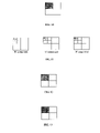
- FIGs. 7–13 are schematic diagrams illustrating color components of a transformed color image and associated computations to code the transformed image for one particular embodiment
- FIG. 14 is a schematic diagram illustrating the architecture for an embodiment of a color video coding scheme
- FIG. 15 is a sequence of images illustrating a frame that has been coded and reconstructed in accordance with various potential color coding embodiments
- FIG. 16 is a plot illustrating PSNR performance for one of the potential coding embodiments of FIG. 15 ;
- FIG. 17 is a block diagram illustrating a computer readable medium encoded according to an embodiment of the invention.
- an efficient color coding scheme for color video using three dimensional (3-D) discrete wavelet transforms (DWT) employing correlation among different color components is described.
- 3-D three dimensional discrete wavelet transforms
- Other wavelet transforms may be employed within the scope of the claimed subject matter.
- experimental results for such an embodiment are also provided.
- several aspects of the coding were specified; however, this is merely an example embodiment and the claimed subject matter is not limited in scope to these specified coding aspects or to this particular embodiment.
- One aspect of the following embodiment is the notion that a sequence of still images or video may be treated as 3-D data or as a 3-D image.
- One advantage for this particular embodiment is that motion estimation is not employed to perform coding. It shall be noted that for this embodiment this produced levels of compression that typically are not available with conventional approaches. Furthermore, this embodiment is typically less computationally intensive than such conventional approaches.
- RGB red-green-blue
- this embodiment employs RGB format.
- the claimed subject matter is not limited in scope to this particular format.
- the green component may be taken as a reference component for the red and blue components. This may be at least in part because the human eye is more sensitive to luminance and much of the luminance information may be contained in the green component.
- this is merely an example embodiment.
- One embodiment of a method of color coding a sequence of frames may include the following.
- a three-dimensional wavelet transform may be applied to the color components of the sequence of frames or color video. At least one of the color components may be coded. Additionally, an adjustment to at least some remaining color components may be coded relative to the at least one coded color component.
- an embodiment of a method of decoding and reconstructing a sequence of coded color frames includes the following. At least a color component that has been coded is decoded. Adjustments to the at least one decoded color component are decoded to produce remaining color components. An inverse 3-D wavelet transform is applied to the decoded color components to reconstruct the sequence of color frames.
- This particular embodiment, here applied to color video includes the following.
- a multi-resolution wavelet representation such as for a DWT
- a DWT may be employed to provide a simple hierarchical framework for interpreting an image.
- the details of an image generally characterize different physical structures of a scene.
- a coarse to fine approach may be employed to assist in the coding of the transformed image, as well as to result in effective compression.
- the approach When the approach is applied to a video sequence, it may be modified from a 2-D to a 3-D transform.
- a 3-D DWT will decompose the sequence of video frames into 8 subbands—one low frequency 3-D subband (denoted as LLL subband in FIG. 2 ) and seven high frequency 3-D subbands or detailed sub-blocks.
- the input video sequence here designated V
- V may be treated as a 3-D block with the different frames arranged substantially according to time position.
- This sequence in this particular embodiment may be fed to two paths, designated P 1 and P 2 .
- P 1 filtering along the time axis may be applied, in this embodiment with filter function g(n).
- the filtered data again, in this particular embodiment may be sub-sampled, here by 2.
- alternative frames of the block may be retained.
- the frames from this reduced block may be again fed into two paths, here P 3 and P 4 , as illustrated in FIG. 1 .
- filtering may be applied along the rows, again with filter function g(n).
- the filtered data again, in this particular embodiment may be sub-sampled, here by 2.
- alternative columns of the matrix or frame may be retained. This reduced matrix may be fed into two paths, P 5 and P 6 as illustrated in FIG. 1 .
- filtering may be applied along the columns with filter function g(n).
- the filtered data may be sub-sampled by 2.
- Alternative rows of the matrix may be retained. This may produce a detail signal, D 1 .
- filtering may be applied along the columns with filter function h(n), in this particular embodiment.
- the filtered data may be sub-sampled by 2, again, for this particular embodiment.
- Alternative rows of the matrix may be retained. This may produce a detail signal, D 2 .
- filtering may be applied along the rows with filter function h(n).
- the filtered data may be sub-sampled by 2.
- Alternative columns of the matrix may be retained. This reduced matrix may be again split into two paths, P 7 and P 8 in FIG. 1 .
- filtering may be applied along the columns, here with filter function g(n).
- the filtered data may be sub-sampled by 2.
- alternative rows of the matrix may be retained. This may produce a detail signal, D 3 .
- filtering may be applied along the columns, here with filter function h(n).
- the filtered data may be sub-sampled by 2.
- Alternative rows of the matrix may be retained. This may produce a detail signal, D 4 .
- filtering may be applied along the time axis, here with filter function h(n) in this embodiment.
- the filtered data may be sub-sampled by 2, in this embodiment.
- Alternative frames of the block may be retained.
- the frames from this reduced block may be again fed into two paths, P 9 and P 10 in FIG. 1 .
- filtering may be applied along the rows, with filter function g(n) in this embodiment.
- the filtered data may be sub-sampled by 2.
- alternative columns of the matrix or frame may be retained. This reduced matrix may be again fed into two paths, P 11 and P 12 in FIG. 1 .
- filtering may be applied along the columns, here with filter function g(n).
- the filtered data may be sub-sampled by 2.
- alternative rows of the matrix may be retained. This may produce a detail signal, D 5 .
- filtering may be applied along the columns, here with filter function h(n).
- the filtered data may be sub-sampled by 2.
- alternative rows of the matrix may be retained. This may produce a detail signal, D 6 .
- filtering may be applied along the rows, here using h(n).
- the filtered data may be sub-sampled by 2.
- Alternative columns of the matrix may be retained. This reduced matrix may again be split into two paths, P 13 and P 14 in this embodiment.
- filtering may be applied along the columns with filter function g(n).
- the filtered data may be sub-sampled, here by 2. Alternative rows may be retained. This may produce a detail signal, D 7 .
- filtering may be applied along the columns with filter function h(n) in this embodiment.
- the filtered data may be sub-sampled by 2. Therefore, alternative rows of the matrix may be retained. This may produce a detail signal, V′.
- seven detail subblocks may be extracted that provide the variations of the edge information, eg, horizontal, vertical and diagonal, with time.
- the other, or eighth, subblock or component, in this embodiment may be the applied video sequence at a lower resolution, due to low pass filtering, such as by h(n) in this embodiment. Applying compression to produce these blocks, such as described in more detail hereinafter, for example, therefore, may produce 3-D coding.
- a method of applying an inverse three-dimensional discrete wavelet transformation (3D IDWT) to a plurality of transformed video image sub-blocks, the sub-blocks comprising transformed frames, and the frames comprising rows and columns, may include the following.
- the transformed video image sub-blocks may be inverse transformed by: up-sampling the respective sub-blocks by row, column and frame; filtering and combining one or more respective pairs of up-sampled sub-blocks to produce an up-sampled sub-block corresponding to each respective pair; reapplying the previous to any produced up-sampled sub-block pairs until one up-sampled sub-block remains; multiplying the one remaining up-sampled sub-block by eight to produce a block at the next higher resolution.
- Detail signal D 1 may be up-sampled. For example, a row of zeros may be inserted between adjacent rows. This sub-block may then be filtered along the columns with the filter function g(n). Detail signal D 2 may be up-sampled. For example, a row of zeros may be inserted between adjacent rows. This sub-block may then be filtered along the columns with the filter function h(n). The resulting output signals from applying the foregoing processes to D 1 and D 2 are added, as illustrated in FIG. 3 . The resultant sub-block may be up-sampled. For example, a column of zeros may be inserted between adjacent columns. This matrix may then be filtered along the rows with the filter function g(n) to produce interim signals I 1 .
- Detail signal D 3 may be up-sampled. For example, a row of zeros may be inserted between rows. This sub-block may then be filtered along the columns with the filter function g(n). Detail signal D 4 may be up-sampled. For example, a row of zeros may be inserted between rows. This sub-block may then be filtered along the columns with the filter function h(n). The resultant output signals from applying the foregoing processes to D 3 and D 4 may be added. The resultant sub-block may be up-sampled. For example, a column of zeros may be inserted between columns. This matrix may then then filtered along the rows with the filter function h(n). The resultant output signals here may be added with interim signals I 1 . The resultant sub-block may be up-sampled. For example, a frame of zeros may be inserted between frames. This matrix may be then filtered along the frames with the filter function g(n) to produce interim signals I 2 .
- Detail signal D 5 may be up-sampled. For example, a row of zeros may be inserted between adjacent rows. This sub-block may then be filtered along the columns with the filter function g(n). Detail signal D 6 may be up-sampled. For example, a row of zeros may be inserted between adjacent rows. This sub-block may then be filtered along the columns with the filter function h(n). The resulting output signals from applying the foregoing processes to D 5 and D 6 may be added, as illustrated in FIG. 3 . The resultant sub-block may be up-sampled. For example, a column of zeros may be inserted between adjacent columns. This matrix may then be filtered along the rows with the filter function g(n) to produce interim signals I 3 .
- Detail signal D 7 may be up-sampled. For example, a row of zeros may be inserted between rows. This sub-block may then be filtered along the columns with the filter function g(n). Detail signal V′ may be up-sampled. For example, a row of zeros may be inserted between rows. This sub-block may then be filtered along the columns with the filter function h(n). The resultant output signals may be added. The resultant sub-block may be up-sampled. For example, a column of zeros may be inserted between columns. This matrix may then be filtered along the rows with the filter function h(n). The resultant output signals may be added with interim signals I 3 . The resultant sub-block may be up-sampled.
- a frame of zeros may be inserted between frames.
- This matrix may then be filtered along the frames with the filter function h(n).
- the resultant output signals may be added with interim signals I 2 .
- the resultant sub-block may be multiplied by 8 to get the sub-matrix to the next level of resolution. diagram as shown in FIG. 3 .
- Quantization factors that may be applied to different blocks at the highest level of 3-D wavelet coefficients are given in table 1 (refer to FIG. 2 for block numbers). Quantization factors for other blocks may be derived from the quantization factor applied to the block at the next higher level (but at the same orientation) by multiplying with 2. These quantization parameters have been generated by evaluation on a number of color video clips. Of course, the claimed subject matter is not limited in scope to these parameters or to employing quantization. However, in this particular embodiment, the wavelet coefficients for the associated sub-blocks are divided by these factors prior to coding.
- a DWT transformed G color plane in a 3D sequence may be encoded as described, for example, in “ Method and Apparatus for Coding of Wavelet Transformed Coefficients ” U.S. patent application Ser. No. 09/867,781.
- One particular video embodiment is provided below, although the claimed subject matter is not limited in scope to this particular embodiment.
- a 3D wavelet transform decomposes an image into seven subbands, one low frequency subband (e.g., LLL) and seven high frequency subbands (e.g., LLH, LHL, LHH, HLL, HLH, HHL, HHH).
- the LLL subband has the characteristics of the original image and may be decomposed in multiple levels.
- the decomposition may be applied up to 4 levels and, in this example, levels of the transform are numbered as in FIG. 4 .
- the coefficients may be scanned in a particular pattern.
- the coefficients may be scanned in such a way so that no finer level coefficients are scanned before the coarser ones (indicated in diagonal and horizontal lines in FIG. 4 ).
- the parent-child relationship for a zero tree search (ZTR) is also illustrated in FIG. 4 .
- the LLL band does not take part in the coding sequence in this particular embodiment. Here, it may be transmitted without changes. For example, any lossless coding method may be applied for this transmission.
- the starting threshold for the coding may be taken as 1 in this particular embodiment. In successive passes, the threshold may bedoubled. The total number of such passes may be ⁇ log 2 (max) ⁇ +1, where “max” in this embodiment denotes the maximum value among the magnitudes of all the coefficients to be encoded.
- a bit-based conditional coding scheme may also be applied in this particular embodiment, e.g., for a symbol, such as P, N, R, IZ , either bit 1 or 0 is coded, depending on the condition whether it is true or false.
- a symbol such as P, N, R, IZ
- FIG. 6 A flowchart is shown in FIG. 5 depicting the coding embodiment, whereas the corresponding decoding scheme is shown in FIG. 6 in the form of a state diagram.
- this coding scheme applied to a 2-D example is explained in more detail in the aforementioned U.S. patent application Ser. No. 09/867,781.
- Coefficients of R and B planes may be coded using a technique described in “ Method of Compressing a Color Image ” U.S. patent application Ser. No. 09/411,697; although, of course, the claimed subject matter is not limited in scope in this respect.
- Applying this coding scheme to video 3-D wavelet transformed coefficient planes for different color planes are shown in FIG. 7 .
- two coefficients, coeff_r and coeff_b, for the different subbands may be calculated and transmitted.
- R′, B′ coefficient value matrices may be constructed as follows.
- values G′ coefficients *coeff_r may be stored in corresponding places of the R matrix.
- R ′( i,j ) G ′( i,j )*coeff — r* *Values of coegg_r and coeff_b are different for different subbands.
- values G′ coefficients *coeff_b may be stored in corresponding places of the B matrix.
- B ′( i,j ) G ′( i,j )*coeff — b
- the partial error matrix may be entropy decoded and then corresponding values may be added to previously estimated R′ coefficient values.
- new R ( i,j ) R ′( i,j )+ R _error( i,j )
- the partial error matrix may be entropy decoded and then corresponding values may be added to the previously estimated B′ coefficient values.
- new B ( i,j ) B ′( i,j )+ B _error( i,j )
- FIG. 14 A schematic diagram of this embodiment of a color video coding scheme is shown in FIG. 14 . Decoding is obtained from reversing the process, as just described.
- one embodiment may be in hardware, such as implemented to operate on an integrated circuit chip, for example, whereas another embodiment may be in software.
- an embodiment may be in firmware, or any combination of hardware, software, or firmware, for example.
- one embodiment may comprise an article, such as a storage medium 1701 .
- a storage medium such as, for example, a CD-ROM 1701 , or a disk, may have stored thereon instructions, which when executed by a system, such as a computer system or platform 1705 .
- an imaging or video system 1707 may result in an embodiment of a method in accordance with the claimed subject matter being executed, such as an embodiment of a method of color video coding, for example, as previously described.
- an image or video processing platform 1707 or another processing system may include a video or image processing unit 1709 , a video or image input/output device 1711 and/or memory 1713 .
Abstract
Description
- 1. R, G, and B components of a color video sequence are independently 3-D wavelet transformed to give 3-D Wavelet coefficients of individual color components, such as R, G, B.
- 2. G color plane coefficients, in this embodiment, are coded using 3-D wavelet coding.
- 3. R and B color plane coefficients, in this embodiment, are coded with respect to G plane coefficients.
These tasks are discussed in detail below.
| TABLE 1 |
| Different Uniform Scalar Quantization parameters |
| imposed on different subband decomposed 3-D blocks |
| as shown in FIG. 2. |
| Blk 2 | |
|
|
|
|
|
||
| Quantization | 1.15 | 1.15 | 1.4 | 1.2 | 1.25 | 1.54 | 1.7 |
| values | |||||||
coeff— r=r/g & coeff— b=b/g
where r, g, b are calculated on the coefficient values of the shaded regions shown in
R_error (i,j)=R(i,j)−coeff— r*G(i,j)
The values of the error in the shaded region as shown in
B_error (i,j)=B(i,j)−coeff— b*G(i,j)
The values in the shaded region, again, may be entropy coded and transmitted.
R′(i,j)=G′(i,j)*coeff— r*
*Values of coegg_r and coeff_b are different for different subbands.
B′(i,j)=G′(i,j)*coeff— b
new R(i,j)=R′(i,j)+R_error(i,j)
-
- for all i, j in the shaded region of
FIG. 12 , for example.
- for all i, j in the shaded region of
new B(i,j)=B′(i,j)+B_error(i,j)
-
- for all i, j in the shaded region of
FIG. 13 , for example.
- for all i, j in the shaded region of
- Case 1: R, G, B components were coded by the stated approach without quantization of the G component.
- Case 2: In addition to the earlier case no outermost subbands of B and R components were transmitted.
- Case 3: In addition to the earlier case the G component was quantized.
- Case 4: In addition to the earlier case, quantization of B and R components was performed
The results obtained were quite satisfactory, as shown in table 2.
| TABLE 2 |
| Compression ratios and PSNR values for different cases |
| Case | B (PSNR) | G (PSNR) | R (PSNR) | Compression |
| (1) | 37.0 | 37.91 | 36.38 | 8.13 |
| (2) | 36.51 | 37.91 | 35.91 | 9.03 |
| (3) | 32.21 | 31.74 | 30.77 | 21.89 |
| (4) | 31.32 | 31.74 | 30.19 | 74.25 |
Claims (28)
Priority Applications (1)
| Application Number | Priority Date | Filing Date | Title |
|---|---|---|---|
| US10/206,908 US7106910B2 (en) | 1999-10-01 | 2002-07-25 | Color video coding scheme |
Applications Claiming Priority (4)
| Application Number | Priority Date | Filing Date | Title |
|---|---|---|---|
| US09/411,697 US6798901B1 (en) | 1999-10-01 | 1999-10-01 | Method of compressing a color image |
| US09/867,781 US6834123B2 (en) | 2001-05-29 | 2001-05-29 | Method and apparatus for coding of wavelet transformed coefficients |
| US09/867,784 US6956903B2 (en) | 2001-05-29 | 2001-05-29 | Method and apparatus for three-dimensional wavelet transform |
| US10/206,908 US7106910B2 (en) | 1999-10-01 | 2002-07-25 | Color video coding scheme |
Related Parent Applications (1)
| Application Number | Title | Priority Date | Filing Date |
|---|---|---|---|
| US09/867,784 Continuation-In-Part US6956903B2 (en) | 1999-10-01 | 2001-05-29 | Method and apparatus for three-dimensional wavelet transform |
Publications (2)
| Publication Number | Publication Date |
|---|---|
| US20040017952A1 US20040017952A1 (en) | 2004-01-29 |
| US7106910B2 true US7106910B2 (en) | 2006-09-12 |
Family
ID=30770385
Family Applications (1)
| Application Number | Title | Priority Date | Filing Date |
|---|---|---|---|
| US10/206,908 Expired - Fee Related US7106910B2 (en) | 1999-10-01 | 2002-07-25 | Color video coding scheme |
Country Status (1)
| Country | Link |
|---|---|
| US (1) | US7106910B2 (en) |
Cited By (18)
| Publication number | Priority date | Publication date | Assignee | Title |
|---|---|---|---|---|
| US20050111741A1 (en) * | 2003-11-26 | 2005-05-26 | Samsung Electronics Co., Ltd. | Color image residue transformation and/or inverse transformation method and apparatus, and color image encoding and/or decoding method and apparatus using the same |
| US20060164510A1 (en) * | 2005-01-24 | 2006-07-27 | Doron Adler | Sensor with narrow mounting profile |
| US20080310506A1 (en) * | 2007-06-15 | 2008-12-18 | Microsoft Corporation | Joint Spatio-Temporal Prediction for Video Coding |
| US20090046171A1 (en) * | 2007-08-16 | 2009-02-19 | C2Cure, Inc. | Non-linear color correction |
| US7758499B2 (en) | 2001-08-10 | 2010-07-20 | C2Cure, Inc. | Method and apparatus for viewing through blood |
| US20100225789A1 (en) * | 2008-11-14 | 2010-09-09 | ATI Technologies LLC | Image noise filter and method |
| US8194121B2 (en) | 2002-05-16 | 2012-06-05 | C2Cure, Inc. | Miniature camera head |
| US8326065B2 (en) | 2004-11-09 | 2012-12-04 | Samsung Electronics Co., Ltd. | Method and apparatus for encoding image data including generation of bit streams |
| US20130156334A1 (en) * | 2011-12-19 | 2013-06-20 | Dolby Laboratories Licensing Corporation | Video Codecs With Integrated Gamut Management |
| US8767817B1 (en) | 2011-04-07 | 2014-07-01 | Google Inc. | Apparatus and method for coding using parameterized equation |
| US8798131B1 (en) | 2010-05-18 | 2014-08-05 | Google Inc. | Apparatus and method for encoding video using assumed values with intra-prediction |
| US9257763B2 (en) | 2013-07-02 | 2016-02-09 | Gyrus Acmi, Inc. | Hybrid interconnect |
| US9344742B2 (en) | 2012-08-10 | 2016-05-17 | Google Inc. | Transform-domain intra prediction |
| US9369732B2 (en) | 2012-10-08 | 2016-06-14 | Google Inc. | Lossless intra-prediction video coding |
| US9510739B2 (en) | 2013-07-12 | 2016-12-06 | Gyrus Acmi, Inc. | Endoscope small imaging system |
| US9615100B2 (en) | 2012-08-09 | 2017-04-04 | Google Inc. | Second-order orthogonal spatial intra prediction |
| US9628790B1 (en) | 2013-01-03 | 2017-04-18 | Google Inc. | Adaptive composite intra prediction for image and video compression |
| US9781447B1 (en) | 2012-06-21 | 2017-10-03 | Google Inc. | Correlation based inter-plane prediction encoding and decoding |
Families Citing this family (7)
| Publication number | Priority date | Publication date | Assignee | Title |
|---|---|---|---|---|
| US6636167B1 (en) * | 2000-10-31 | 2003-10-21 | Intel Corporation | Method of generating Huffman code length information |
| US6563439B1 (en) * | 2000-10-31 | 2003-05-13 | Intel Corporation | Method of performing Huffman decoding |
| CN102592308B (en) * | 2011-11-30 | 2013-11-27 | 天津大学 | Single-camera video three-dimensional reconstruction method based on wavelet transformation |
| CN105654472B (en) * | 2015-12-25 | 2018-10-23 | 陕西师范大学 | A kind of projective reconstruction method based on track base |
| RU2616176C1 (en) * | 2016-03-28 | 2017-04-12 | Федеральное государственное бюджетное образовательное учреждение высшего образования "Тульский государственный университет" (ТулГУ) | Method for encoding-decoding of digital video images |
| CN106097328B (en) * | 2016-06-07 | 2019-05-14 | 陕西师范大学 | A kind of image missing values restoration methods based on non-rigid track base |
| EP3471418A1 (en) | 2017-10-12 | 2019-04-17 | Thomson Licensing | Method and apparatus for adaptive transform in video encoding and decoding |
Citations (30)
| Publication number | Priority date | Publication date | Assignee | Title |
|---|---|---|---|---|
| US5875122A (en) | 1996-12-17 | 1999-02-23 | Intel Corporation | Integrated systolic architecture for decomposition and reconstruction of signals using wavelet transforms |
| US5956467A (en) * | 1996-12-17 | 1999-09-21 | Eastman Kodak Company | Encoding color image data for multipass color printers |
| US5995210A (en) | 1998-08-06 | 1999-11-30 | Intel Corporation | Integrated architecture for computing a forward and inverse discrete wavelet transforms |
| US6009206A (en) | 1997-09-30 | 1999-12-28 | Intel Corporation | Companding algorithm to transform an image to a lower bit resolution |
| US6009201A (en) | 1997-06-30 | 1999-12-28 | Intel Corporation | Efficient table-lookup based visually-lossless image compression scheme |
| US6047303A (en) | 1998-08-06 | 2000-04-04 | Intel Corporation | Systolic architecture for computing an inverse discrete wavelet transforms |
| US6091851A (en) | 1997-11-03 | 2000-07-18 | Intel Corporation | Efficient algorithm for color recovery from 8-bit to 24-bit color pixels |
| US6094508A (en) | 1997-12-08 | 2000-07-25 | Intel Corporation | Perceptual thresholding for gradient-based local edge detection |
| US6108453A (en) | 1998-09-16 | 2000-08-22 | Intel Corporation | General image enhancement framework |
| US6124811A (en) | 1998-07-02 | 2000-09-26 | Intel Corporation | Real time algorithms and architectures for coding images compressed by DWT-based techniques |
| US6130960A (en) | 1997-11-03 | 2000-10-10 | Intel Corporation | Block-matching algorithm for color interpolation |
| US6151069A (en) | 1997-11-03 | 2000-11-21 | Intel Corporation | Dual mode digital camera for video and still operation |
| US6151415A (en) | 1998-12-14 | 2000-11-21 | Intel Corporation | Auto-focusing algorithm using discrete wavelet transform |
| US6154493A (en) | 1998-05-21 | 2000-11-28 | Intel Corporation | Compression of color images based on a 2-dimensional discrete wavelet transform yielding a perceptually lossless image |
| US6166664A (en) | 1998-08-26 | 2000-12-26 | Intel Corporation | Efficient data structure for entropy encoding used in a DWT-based high performance image compression |
| US6178269B1 (en) | 1998-08-06 | 2001-01-23 | Intel Corporation | Architecture for computing a two-dimensional discrete wavelet transform |
| US6195026B1 (en) | 1998-09-14 | 2001-02-27 | Intel Corporation | MMX optimized data packing methodology for zero run length and variable length entropy encoding |
| US6215908B1 (en) | 1999-02-24 | 2001-04-10 | Intel Corporation | Symmetric filtering based VLSI architecture for image compression |
| US6215916B1 (en) | 1998-02-04 | 2001-04-10 | Intel Corporation | Efficient algorithm and architecture for image scaling using discrete wavelet transforms |
| US6229578B1 (en) | 1997-12-08 | 2001-05-08 | Intel Corporation | Edge-detection based noise removal algorithm |
| US6233358B1 (en) | 1998-07-13 | 2001-05-15 | Intel Corporation | Image compression using directional predictive coding of the wavelet coefficients |
| US6236765B1 (en) | 1998-08-05 | 2001-05-22 | Intel Corporation | DWT-based up-sampling algorithm suitable for image display in an LCD panel |
| US6236433B1 (en) | 1998-09-29 | 2001-05-22 | Intel Corporation | Scaling algorithm for efficient color representation/recovery in video |
| US6275206B1 (en) | 1999-03-17 | 2001-08-14 | Intel Corporation | Block mapping based up-sampling method and apparatus for converting color images |
| US6285796B1 (en) | 1997-11-03 | 2001-09-04 | Intel Corporation | Pseudo-fixed length image compression scheme |
| US6292114B1 (en) | 1999-06-10 | 2001-09-18 | Intel Corporation | Efficient memory mapping of a huffman coded list suitable for bit-serial decoding |
| US6611620B1 (en) * | 1998-08-28 | 2003-08-26 | Matsushita Electric Industrial Co. Ltd. | Reversible coding method, reversible coding apparatus, and memory medium used therein |
| US6798901B1 (en) * | 1999-10-01 | 2004-09-28 | Intel Corporation | Method of compressing a color image |
| US6834123B2 (en) * | 2001-05-29 | 2004-12-21 | Intel Corporation | Method and apparatus for coding of wavelet transformed coefficients |
| US6850570B1 (en) * | 1999-10-28 | 2005-02-01 | Koninklijke Philips Electronics N.V. | Color video encoding method based on a wavelet decomposition |
-
2002
- 2002-07-25 US US10/206,908 patent/US7106910B2/en not_active Expired - Fee Related
Patent Citations (31)
| Publication number | Priority date | Publication date | Assignee | Title |
|---|---|---|---|---|
| US5956467A (en) * | 1996-12-17 | 1999-09-21 | Eastman Kodak Company | Encoding color image data for multipass color printers |
| US5875122A (en) | 1996-12-17 | 1999-02-23 | Intel Corporation | Integrated systolic architecture for decomposition and reconstruction of signals using wavelet transforms |
| US6009201A (en) | 1997-06-30 | 1999-12-28 | Intel Corporation | Efficient table-lookup based visually-lossless image compression scheme |
| US6009206A (en) | 1997-09-30 | 1999-12-28 | Intel Corporation | Companding algorithm to transform an image to a lower bit resolution |
| US6091851A (en) | 1997-11-03 | 2000-07-18 | Intel Corporation | Efficient algorithm for color recovery from 8-bit to 24-bit color pixels |
| US6269181B1 (en) | 1997-11-03 | 2001-07-31 | Intel Corporation | Efficient algorithm for color recovery from 8-bit to 24-bit color pixels |
| US6285796B1 (en) | 1997-11-03 | 2001-09-04 | Intel Corporation | Pseudo-fixed length image compression scheme |
| US6130960A (en) | 1997-11-03 | 2000-10-10 | Intel Corporation | Block-matching algorithm for color interpolation |
| US6151069A (en) | 1997-11-03 | 2000-11-21 | Intel Corporation | Dual mode digital camera for video and still operation |
| US6094508A (en) | 1997-12-08 | 2000-07-25 | Intel Corporation | Perceptual thresholding for gradient-based local edge detection |
| US6229578B1 (en) | 1997-12-08 | 2001-05-08 | Intel Corporation | Edge-detection based noise removal algorithm |
| US6215916B1 (en) | 1998-02-04 | 2001-04-10 | Intel Corporation | Efficient algorithm and architecture for image scaling using discrete wavelet transforms |
| US6154493A (en) | 1998-05-21 | 2000-11-28 | Intel Corporation | Compression of color images based on a 2-dimensional discrete wavelet transform yielding a perceptually lossless image |
| US6124811A (en) | 1998-07-02 | 2000-09-26 | Intel Corporation | Real time algorithms and architectures for coding images compressed by DWT-based techniques |
| US6233358B1 (en) | 1998-07-13 | 2001-05-15 | Intel Corporation | Image compression using directional predictive coding of the wavelet coefficients |
| US6236765B1 (en) | 1998-08-05 | 2001-05-22 | Intel Corporation | DWT-based up-sampling algorithm suitable for image display in an LCD panel |
| US6047303A (en) | 1998-08-06 | 2000-04-04 | Intel Corporation | Systolic architecture for computing an inverse discrete wavelet transforms |
| US5995210A (en) | 1998-08-06 | 1999-11-30 | Intel Corporation | Integrated architecture for computing a forward and inverse discrete wavelet transforms |
| US6178269B1 (en) | 1998-08-06 | 2001-01-23 | Intel Corporation | Architecture for computing a two-dimensional discrete wavelet transform |
| US6166664A (en) | 1998-08-26 | 2000-12-26 | Intel Corporation | Efficient data structure for entropy encoding used in a DWT-based high performance image compression |
| US6611620B1 (en) * | 1998-08-28 | 2003-08-26 | Matsushita Electric Industrial Co. Ltd. | Reversible coding method, reversible coding apparatus, and memory medium used therein |
| US6195026B1 (en) | 1998-09-14 | 2001-02-27 | Intel Corporation | MMX optimized data packing methodology for zero run length and variable length entropy encoding |
| US6108453A (en) | 1998-09-16 | 2000-08-22 | Intel Corporation | General image enhancement framework |
| US6236433B1 (en) | 1998-09-29 | 2001-05-22 | Intel Corporation | Scaling algorithm for efficient color representation/recovery in video |
| US6151415A (en) | 1998-12-14 | 2000-11-21 | Intel Corporation | Auto-focusing algorithm using discrete wavelet transform |
| US6215908B1 (en) | 1999-02-24 | 2001-04-10 | Intel Corporation | Symmetric filtering based VLSI architecture for image compression |
| US6275206B1 (en) | 1999-03-17 | 2001-08-14 | Intel Corporation | Block mapping based up-sampling method and apparatus for converting color images |
| US6292114B1 (en) | 1999-06-10 | 2001-09-18 | Intel Corporation | Efficient memory mapping of a huffman coded list suitable for bit-serial decoding |
| US6798901B1 (en) * | 1999-10-01 | 2004-09-28 | Intel Corporation | Method of compressing a color image |
| US6850570B1 (en) * | 1999-10-28 | 2005-02-01 | Koninklijke Philips Electronics N.V. | Color video encoding method based on a wavelet decomposition |
| US6834123B2 (en) * | 2001-05-29 | 2004-12-21 | Intel Corporation | Method and apparatus for coding of wavelet transformed coefficients |
Non-Patent Citations (90)
| Title |
|---|
| " Signal to Noise Ration Optimization for Video Compression Bit-Rate Control", U.S. Appl. No. 09/947,331, filed Sep. 5, 2001, 25 Pgs. |
| "A Block-Matching Algorithm for Color Interpolation", Inventor: Acharya, U.S. Appl. No. 09/494,087, filed Jan. 28, 2000, 45 Pgs. |
| "A Fuzzy Based Thresholding Technique for Image Segmentation", Inventors: Acharya, et al., U.S. Appl. No. 09/393,136, filed Sep. 10, 1999, 28 Pgs. |
| "A Fuzzy Distinction Based Thresholding Technique for Image Segmentation" Inventors: Acharya, et al., U.S. Appl. No. 09/393,017, filed Sep. 10, 1999, 29 Pgs. |
| "A Hardware Efficient Wavelet-Based Video Compression Scheme", Inventors: Tan, et al., U.S. Appl. No. 09/342,863, filed Jun. 29, 1999, 32 Pgs. |
| "A Mathematical Model for Gray Scale and Contrast Enhancement of a Digital Image", Inventor: Acharya, U.S. Appl. No. 09/207,753, filed Dec. 8, 1998, 28 Pages. |
| "A Median Computation-Based Integrated Color Interpolation and Color Space Conversion Methodology From 8-Bit Bayer Pattern RGB Color Space to 24-Bit CIE XYZ Color Space", Inventor: Acharya, U.S. Appl. No. 09/050,743, filed Mar. 30,, 1998, 37 Pgs. |
| "A Median Computation-Based Integrated Color Interpolationi and Color Space Conversion Methodology From 8-Bit Bayer Pattern RGB Color Space to 12-Bit YCrCb Color Space", Inventor: Acharya, U.S. Appl. No. 09/040,806, filed Mar. 18, 1998, 43 Pgs. |
| "A Memory Based VLSI Architecture for Image Compression", Inventor: Acharya, U.S. Appl. No. 09/885,415, filed Jun. 30, 1997, 37 Pgs. |
| "A Method for Block-Based Digital Image Watermarking", Inventors: Acharya, et al., filed Nov. 29, 2000, 11 Pgs. |
| "A Method of Generating Huffman Code Length Information", Inventors: Acharya, et al., U.S. Appl. No. 09/704,392, filed Oct. 31, 2000, 25 Pgs. |
| "A Method of Performing Huffman Decoding", Inventors: Acharya, et al., U.S. Appl. No. 09/704,380, filed Oct. 31, 2000, 26 Pgs. |
| "A Methodology for Color Correction With Noise Regulation", Inventors: Tan, et al., U.S. Appl. No. 09/359,831, filed Jul. 23, 1999, 30 Pgs. |
| "A New Scaling Algorithm and Architecture for Integer Scaling in Video", Inventor: Acharya, et al., U.S. Appl. No. 09/008,131, filed Jan. 16, 1998, 38 Pgs. |
| "An Edge Enhanced Image Up-Sampling Algorithm Using Discrete Wavelet Transform", Inventors: Acharya, et al., U.S. Appl. No. 09/292,763, filed Apr. 14, 1999, 32 Pgs. |
| "An Efficient Companding Algorithm Suitable for Color Imaging", Inventors: Acharya, et al., U.S. Appl. 09/482,551, filed Jan. 13, 2000, 44 Pgs. |
| "An Efficient Methodology to Select the Quantization Threshold Parameters in a DWT-Based Image Compression Scheme in Order to Store a Predefined Minimum Number of Images into a Fixed Size Secondary Storage", Inventor: Acharya, U.S. Appl. No. 09/146,159, filed Sep. 3, 1998, 35 Pgs. |
| "An Integrated Color Interpolation and Color Space Conversion Algorithm From 8-Bit Bayer Pattern RGB Color Space to 12-Bit YCRCB Color Space", Inventor: Acharya, U.S. Appl. No. 10/022,154, filed Dec. 14, 2001, 32 Pgs. |
| "An Integrated Color Interpolation and Color Space Conversion Algorithm From 8-Bit Bayer Pattern RGB Color Space to 24-Bit CIE XYZ Color Space", Inventor: Acharya, U.S. Appl. No. 09/048,901, filed Mar. 26, 1998, 36 Pgs. |
| "Architecture for Processing Fingerprint Images", Inventors: Acharya, et al., U.S. Appl. No. 09/952,276, filed Sep. 13, 2001, 19 Pgs. |
| "Chip Rate Selectable Square Root Raised Consine Filter for Mobile Telecommunication", Inventors: Acharya, et al., U.S. Appl. No. 09/467,487, filed Dec. 20, 1999, 44 Pgs. |
| "Color Filter Array and Color Imterpolation Algorithm", Inventors: Acharya, et al., U.S. Appl. No. 09/727,038, filed Nov. 30, 2000, 36 Pgs. |
| "Color Interpolation for a Four Color Mosaic Pattern", Inventors: Acharya, et al., U.S. Appl. No. 09/199,836, filed Nov. 24, 1998, 26 Pgs. |
| "Computing the Euler Number of a Binary Image", Inventors: Acharya, et al., U.S. Appl. No. 09/722,982, filed Nov. 27, 2000, 31 Pgs. |
| "Developing an Euler Vector for Images", Inventors: Acharya, et al., U.S. Appl. No. 09/722, 979, filed Nov. 27, 2000, 45 Pgs. |
| "Discrete Filter", Inventor: Acharya, U.S. Appl. No. 09/432,337, filed Nov. 2, 1999, 16 Pgs. |
| "Dual Mode Digital Camera for Video and Still Operation", Inventors: Dunton, et al., U.S. Appl. No. 09/595,055, filed Jun. 16, 2000, 30 Pgs. |
| "Dual Mode Filter for Mobile Telecommunications", Inventors: Miao, et al., U.S. Appl. No. 09/467,611, filed Dec. 20, 1999, 49 Pgs. |
| "Encoding of Wavelet Transformed Error Data", Inventor: Acharya, et al., U.S. Appl. No. 09/723,123, filed Nov. 27, 2000, 38 Pgs. |
| "Enhancing Image Compression Performance by Morphological Processing", Inventor: Acharya, U.S. Appl. No. 09/291,810, filed Apr. 14, 1999, 31 Pgs. |
| "Fast Half-Pixel Motion Estimation Using Steepest Decent", U.S. Appl. No. 09/947,266, filed Sep. 5, 2001, 19 Pgs. |
| "Hi-Speed Deterministic Approach in Detecting Defective Pixels Within an Image Sensor" Inventors: Tan, et al., U.S. Appl. No. 09/258,636, filed Feb. 26, 1999, 32 Pgs. |
| "Image Processing Architecture", Inventors: Metz, et al., U.S. Appl. No. 09/473,643, filed Dec. 28, 1999, 16 Pgs. |
| "Image Processing Method and Apparatus", Inventors: Acharya, et al., U.S. Appl. No. 09/359,523, filed Jul. 23, 1999, 16 Pgs. |
| "Image Retrieval Using Distance Measure", Inventors: Acharya, et al., U.S. Appl. No. 09/817,000, filed Mar. 23, 2001, 28 Pgs. |
| "Imaging Device Connected to Processor-Based System Using High-Bandwidth Bus", Inventors: Acharya, et al., U.S. Appl. No. 09/726,773, filed Nov. 29, 2000, 31 Pgs. |
| "Indexing Wavelet Compressed Video", Inventors: Acharya, et al., U.S. Appl. No. 09/438,091, filed Nov. 10, 1999, 29 Pgs. |
| "Infrared Correction System", Inventors: Bawolek, et al., U.S. Appl. No. 09/126,203, filed Jul. 30, 1998, 23 Pgs. |
| "Method and Apparatus for Adaptively Sharpening an Image", Inventors: Tsai, et al., U.S. Appl. No. 09/320,192, filed May 26, 1999, 27 Pgs. |
| "Method and Apparatus for Adaptively Sharpening Local Image Content of an Image", Inventors: Tan, et al., U.S. Appl. No. 09/328,935, filed Jun. 9, 1999, 29 Pgs. |
| "Method and Apparatus for Automatic Foocusing an Image Capture System Using Symmetric Fir Filters", Inventors: Tan, et al., U.S. Appl. No. 09/383,117, filed Aug. 25, 1999, 28 Pgs. |
| "Method and Apparatus for Coding of Wavelet Transformed Coefficients", Inventors: Acharya, et al., U.S. Appl. No. 09/867, 781, filed May 29, 2001, 44 Pgs. |
| "Method and Apparatus for Image Scaling", Inventor: Acharya, U.S. Appl. No. 09/917,476, filed Jul. 27, 2001, 19 Pgs. |
| "Method and Apparatus for Multiply-Accumulate Two-Dimensional Separable Symmetric Filtering", U.S. Appl. No. 09/718,877, filed Nov. 20, 2000, 13 Pgs. |
| "Method and Apparatus for Providing a Binary Fingerprint Image", Inventors Acharya, et al., U.S. Appl. No. 09/952,284, filed Sep. 13, 2001, 26 Pgs. |
| "Method and Apparatus for Three-Dimensional Wavelet Transform", Inventors: Acharya, U.S. Appl. No. 09/867,784, filed May 29, 2001, 30 Pgs. |
| "Method and Apparatus for Two-Dimensional Separable Symetric Filtering", U.S. Appl. No. 09/713,663, filed Nov. 15, 2000, 20 Pgs. |
| "Method and Apparatus for Video Bit-Rate Control", Inventors: Kim, et al., U.S. Appl. No. 10/039,462, filed Dec. 28, 2001, 23 Pgs. |
| "Method and Apparatus to Reduce False Minutiae in a Binary Fingerprint Image", Inventors: Acharya, et al., U.S. Appl. No. 09/952,249, filed Sep. 13, 2001, 30 Pgs. |
| "Method of Compressing a Color Image", Inventors: Acharya, et al., U.S. Appl. No. 09/411,697, filed Oct. 1, 1999, 26 Pgs. |
| "Method of Compressing an Image", Inventors: Acharya, et al., U.S. Appl. No. 09/597,354, filed Jun. 19, 2000, 23 Pgs. |
| "Method of Compressing and/or Decompressing a Data Set Using Significance Mapping", Inventors: Pazmino, et al., U.S. Appl. No. 09/151,336, filed Sep. 11, 1998, 25 Pgs. |
| "Method of Converting a Sub-Sampled Color Image", Inventor: Acharya, U.S. Appl. No. 09/461,068, filed Dec. 14, 1999, 22 Pgs. |
| "Method of Geerating a Length-Constrained Huffman Code", Inventors: Acharya, et al., U.S. Appl. No. 09/705,314, filed Jan. 3, 2001, 17 Pgs. |
| "Method of Integrating a Watemark Into a Compressed Image", Inventors: Acharya, et al., U.S. Appl. No. 09/09519,135, filed Mar. 6, 2000, 25 Pgs. |
| "Method of Integrating a Watermark Into an Image", Inventors: Acharya, et al., U.S. Appl. No. 09/519,874, filed Mar. 6, 2000, 27 Pgs. |
| "Method of Interpolating Color Pixel Signals From a Subsampled Color Image", Inventors: Acharya, et al., U.S. Appl. No. 09/410,800, filed Oct. 1, 1999, 20 Pgs. |
| "Method of Inverse Quantizing Quantized Signal Samples of an Image During Image Decompression", Inventors: Acharya, et al., U.S. Appl. No. 09/507,213, filed Feb. 18, 2000, 32 Pgs. |
| "Method of Performing Video Encoding Rate Control Using Bit Budget", Inventors: Kim, et al., U.S. Appl. No. 09/754,682, filed Jan. 3, 2001, 25 Pgs. |
| "Method of Performing Video Encoding Rate Control Using Motion Estimation", Inventors: Kim, et al., U.S. Appl. No. 09/754,683, filed Jan. 3, 2001, 37 Pgs. |
| "Method of Performing Video Encoding Rate Control", Inventors: Kim, et al., U.S. Appl. No. 09/754,227, filed Jan. 3, 2001, 28 Pgs. |
| "Method of Perrforming Motion Estimation", Inventors: Kim, et al., U.S. Appl. No. 09/596,127, filed Jun. 16, 2000, 29 Pgs. |
| "Method of Quantizing Signal Samples of an Image During Image Compression", Inventors: Acharya, et al., U.S. Appl. No. 09.507,399, filed Feb. 18, 2000, 24 Pgs. |
| "Method of Upscaling a Color Image", Inventor: Acharya, U.S. Appl. No. 09/461,080, filed Dec. 14, 1999, 22 Pgs. |
| "Method of Using Hue to Interpolate Color Pixel Signals", Inventors: Acharya, et al., U.S. Appl. No. 09/591,867, filed Jun. 12, 2000, 23 Pgs. |
| "Method of Video Coding Shoulder Movement from a Sequence of Images", Inventors: Acharya, et al., U.S. Appl. No. 09/607,724, filed Jun. 30, 2000, 24 Pgs. |
| "Method of Video Coding the Movement of a Human Face From a Sequence of Images", Inventors: Acharya, et al., U.S. Appl. No. 09/608,989, filed Jun. 30, 2000, 25 Pgs. |
| "Model-Based Video Image Coding", Inventors: Acharya, et al., U.S. Appl. No. 09/608,991, filed Jun. 30, 2000, 36 Pgs. |
| "Multiplierless Pyramid Filter", Inventor: Acharya, U.S. Appl. No. 09/754,684, filed Jan. 3, 2001, 22 Pgs. |
| "Progressive Two-Dimensional (2D) Pyramid Filter", Inventors: Wang, et al., U.S. Appl. No. 10/039,434, filed Dec. 28, 2001, 26 Pgs. |
| "Pyramid Filter", Inventor: Acharya, U.S. Appl. No. 09/820,108, filed Mar. 28, 2001, 23 Pgs. |
| "Reduction of Ringing Artifacts After Decompression of a DWT-Based Compressed Image", Inventors: Tan, et al., U.S. Appl. No. 09/165,511, filed Oct. 2, 1998, 20 Pgs. |
| "Reduction of Ringing Artifacts After Decompression of DWT-Based Compressed Image", Inventors: Tan, et al., U.S. Appl. No. 09/863, 478, filed May 22, 2001, 24 Pgs. |
| "Robust Sequential Approach in Detecting Defective Pixels Within an Image Sensor" Inventors: Tan, et al., U.S. Appl. No. 09/191,310, filed Nov. 13, 1998, 35 Pgs. |
| "Sad Computation Architecture", Inventor: Acharya, U.S. Appl. No. 09/677,829, filed Sep. 29, 2000, 24 Pgs. |
| "Sad Computation Architecture", Inventor: Acharya, U.S. Appl. No. 09/677,830, filed Sep. 29, 2000, 27 Pgs. |
| "Square Root Raised Cosine Symmetric Filter for Mobile Telecommunications", Inventors: Acharya, et al. U.S. Appl. 09/429,058, filed Oct. 29, 1999, 36 Pgs. |
| "Techniques to Implement One-Dimensional Compression", Inventor: Acharya, U.S. Appl. No. 09/666,486, filed Sep. 18, 2000, 18 Pgs. |
| "Techniques to Implement Two-Dimensional Compression", Inventor: Acharya, U.S. Appl. No. 09/664,131, filed Sep. 18, 2000, 24 Pgs. |
| "Two Dimensional Pyramid Filter Architecture", Inventor: Acharya, U.S. Appl. No. 09/823,390, filed Mar. 30, 2001, 38 Pgs. |
| "Two-Dimensional Pyramid Filter Architecture", Inventor: Acharya, U.S. Appl. No. 09/817,711, filed Mar. 26, 2001, 33 Pgs. |
| "Two-Dimensional Pyramid Filter Architecture", Inventor: Acharya, U.S. Appl. No. 09/823,212, filed Mar. 30, 2001, 37 Pgs. |
| "Using an Electronic Camera to Build a File Containing Text", Inventors: Tan, et al., U.S. Appl. No. 09/301,753, filed Apr. 29, 1999, 21 Pgs. |
| "Varialbe Length Coding Packing Architecture", Inventors: Becker, et al., U.S. Appl. No. 09/935,524, filed Aug. 22, 2001, 33 Pgs. |
| "Video Motion Estimation", Inventor: Acharya, U.S. Appl. No. 09/406,032, filed Sep. 27, 1999, 24 Pgs. |
| "Wavelet Coding of Video", Inventors: Acharya, et al., U.S. Appl. No. 09/722,988, filed Nov. 27, 2000, 40 Pgs. |
| "Zerotree Encoding of Wavelet Data", Inventors: Acharya, et al., U.S. Appl. No. 09/390,255, filed Sep. 3, 1999, 22 Pgs. |
| Kim et al., Low-Delay Embedded 3-D Wavelet Color Video Coding, SPIE vol. 3309 0277-786/97, pp. 955-964. * |
| Two-Dimensional Pyramid Filter Architecture:, Inventor: Acharya, U.S. Appl. No. 09/846,609, filed Apr. 30, 2001, 37 Pgs. |
| Weeks et al., 3D Discrete Wavelet Transform Architecture, IEEE 0-7803-4455, iv-57 thru IV-60. * |
Cited By (24)
| Publication number | Priority date | Publication date | Assignee | Title |
|---|---|---|---|---|
| US7758499B2 (en) | 2001-08-10 | 2010-07-20 | C2Cure, Inc. | Method and apparatus for viewing through blood |
| US8194121B2 (en) | 2002-05-16 | 2012-06-05 | C2Cure, Inc. | Miniature camera head |
| US20050111741A1 (en) * | 2003-11-26 | 2005-05-26 | Samsung Electronics Co., Ltd. | Color image residue transformation and/or inverse transformation method and apparatus, and color image encoding and/or decoding method and apparatus using the same |
| US8036478B2 (en) | 2003-11-26 | 2011-10-11 | Samsung Electronics Co., Ltd. | Color image residue transformation and/or inverse transformation method and apparatus, and color image encoding and/or decoding method and apparatus using the same |
| US8326065B2 (en) | 2004-11-09 | 2012-12-04 | Samsung Electronics Co., Ltd. | Method and apparatus for encoding image data including generation of bit streams |
| US20060164510A1 (en) * | 2005-01-24 | 2006-07-27 | Doron Adler | Sensor with narrow mounting profile |
| US20080310506A1 (en) * | 2007-06-15 | 2008-12-18 | Microsoft Corporation | Joint Spatio-Temporal Prediction for Video Coding |
| US9031129B2 (en) | 2007-06-15 | 2015-05-12 | Microsoft Technology Licensing, Llc | Joint spatio-temporal prediction for video coding |
| US20090046171A1 (en) * | 2007-08-16 | 2009-02-19 | C2Cure, Inc. | Non-linear color correction |
| US20100225789A1 (en) * | 2008-11-14 | 2010-09-09 | ATI Technologies LLC | Image noise filter and method |
| US8538189B2 (en) * | 2008-11-14 | 2013-09-17 | Ati Technologies Ulc | Image noise filter and method |
| US8798131B1 (en) | 2010-05-18 | 2014-08-05 | Google Inc. | Apparatus and method for encoding video using assumed values with intra-prediction |
| US8767817B1 (en) | 2011-04-07 | 2014-07-01 | Google Inc. | Apparatus and method for coding using parameterized equation |
| US8934726B2 (en) * | 2011-12-19 | 2015-01-13 | Dolby Laboratories Licensing Corporation | Video codecs with integrated gamut management |
| US20150085925A1 (en) * | 2011-12-19 | 2015-03-26 | Dolby Laboratories Licensing Corporation | Video Codecs with Integrated Gamut Management |
| US20130156334A1 (en) * | 2011-12-19 | 2013-06-20 | Dolby Laboratories Licensing Corporation | Video Codecs With Integrated Gamut Management |
| US9191682B2 (en) * | 2011-12-19 | 2015-11-17 | Dolby Laboratories Licensing Corporation | Video codecs with integrated gamut management |
| US9781447B1 (en) | 2012-06-21 | 2017-10-03 | Google Inc. | Correlation based inter-plane prediction encoding and decoding |
| US9615100B2 (en) | 2012-08-09 | 2017-04-04 | Google Inc. | Second-order orthogonal spatial intra prediction |
| US9344742B2 (en) | 2012-08-10 | 2016-05-17 | Google Inc. | Transform-domain intra prediction |
| US9369732B2 (en) | 2012-10-08 | 2016-06-14 | Google Inc. | Lossless intra-prediction video coding |
| US9628790B1 (en) | 2013-01-03 | 2017-04-18 | Google Inc. | Adaptive composite intra prediction for image and video compression |
| US9257763B2 (en) | 2013-07-02 | 2016-02-09 | Gyrus Acmi, Inc. | Hybrid interconnect |
| US9510739B2 (en) | 2013-07-12 | 2016-12-06 | Gyrus Acmi, Inc. | Endoscope small imaging system |
Also Published As
| Publication number | Publication date |
|---|---|
| US20040017952A1 (en) | 2004-01-29 |
Similar Documents
| Publication | Publication Date | Title |
|---|---|---|
| US7106910B2 (en) | Color video coding scheme | |
| US6834123B2 (en) | Method and apparatus for coding of wavelet transformed coefficients | |
| US6865291B1 (en) | Method apparatus and system for compressing data that wavelet decomposes by color plane and then divides by magnitude range non-dc terms between a scalar quantizer and a vector quantizer | |
| EP0888689B1 (en) | Data compression using hybrid lossless entropy encoding of run-length codes | |
| AU637020B2 (en) | Improved image compression method and apparatus | |
| US6339616B1 (en) | Method and apparatus for compression and decompression of still and motion video data based on adaptive pixel-by-pixel processing and adaptive variable length coding | |
| US6853755B2 (en) | Method and apparatus for adaptive compression of scanned documents | |
| US9510005B2 (en) | Method and device for encoding blocks of values | |
| JPH09261644A (en) | Wavelet video encoding method | |
| KR100561587B1 (en) | Method and apparatus for three-dimensional wavelet transform | |
| JPH06209473A (en) | Error controller | |
| US6445823B1 (en) | Image compression | |
| EP1705924A1 (en) | Moving picture encoding method and device, and moving picture decoding method and device | |
| JPH05505080A (en) | Method and apparatus for processing digital image sequences | |
| JP2004528791A (en) | Inter-frame encoding method and apparatus | |
| Singh et al. | JPEG2000: A review and its performance comparison with JPEG | |
| EP1453320A2 (en) | Image encoding method and arrangement | |
| JP2839987B2 (en) | Image signal decoder | |
| JPH09307897A (en) | Image data compression processing method | |
| Van Assche et al. | Lossless compression of pre-press images using a novel colour decorrelation technique | |
| Li et al. | Wavelet transform approach to video compression | |
| US7787698B2 (en) | Sign coding and decoding | |
| Zhao et al. | Embedded image coding based on hierarchical discrete cosine transform | |
| Lin et al. | Image coding using wavelet transform and classified vector quantisation | |
| JP2571274B2 (en) | Code data storage / readout method |
Legal Events
| Date | Code | Title | Description |
|---|---|---|---|
| AS | Assignment |
Owner name: INDIAN INSTITUTE OF TECHNOLOGY, INDIA Free format text: ASSIGNMENT OF ASSIGNORS INTEREST;ASSIGNOR:BISWAS, PRABIR K.;REEL/FRAME:013526/0990 Effective date: 20021104 Owner name: INTEL CORPORATION, CALIFORNIA Free format text: ASSIGNMENT OF ASSIGNORS INTEREST;ASSIGNOR:ACHARYA, TINKU;REEL/FRAME:013528/0996 Effective date: 20020929 |
|
| CC | Certificate of correction | ||
| FPAY | Fee payment |
Year of fee payment: 4 |
|
| SULP | Surcharge for late payment | ||
| FPAY | Fee payment |
Year of fee payment: 8 |
|
| FEPP | Fee payment procedure |
Free format text: MAINTENANCE FEE REMINDER MAILED (ORIGINAL EVENT CODE: REM.) |
|
| LAPS | Lapse for failure to pay maintenance fees |
Free format text: PATENT EXPIRED FOR FAILURE TO PAY MAINTENANCE FEES (ORIGINAL EVENT CODE: EXP.); ENTITY STATUS OF PATENT OWNER: LARGE ENTITY |
|
| STCH | Information on status: patent discontinuation |
Free format text: PATENT EXPIRED DUE TO NONPAYMENT OF MAINTENANCE FEES UNDER 37 CFR 1.362 |
|
| FP | Lapsed due to failure to pay maintenance fee |
Effective date: 20180912 |