US7043580B1 - Cluster lock server: ability to support multiple standard and proprietary locking protocols - Google Patents
Cluster lock server: ability to support multiple standard and proprietary locking protocols Download PDFInfo
- Publication number
- US7043580B1 US7043580B1 US10/346,458 US34645803A US7043580B1 US 7043580 B1 US7043580 B1 US 7043580B1 US 34645803 A US34645803 A US 34645803A US 7043580 B1 US7043580 B1 US 7043580B1
- Authority
- US
- United States
- Prior art keywords
- cluster
- lock server
- commodity
- instruction processors
- operating system
- Prior art date
- Legal status (The legal status is an assumption and is not a legal conclusion. Google has not performed a legal analysis and makes no representation as to the accuracy of the status listed.)
- Expired - Lifetime, expires
Links
- 238000000034 method Methods 0.000 claims abstract description 40
- 238000012545 processing Methods 0.000 claims abstract description 28
- 230000006870 function Effects 0.000 claims abstract description 18
- 230000015654 memory Effects 0.000 claims abstract description 14
- 238000003860 storage Methods 0.000 claims abstract description 8
- 230000004044 response Effects 0.000 claims description 3
- 238000004590 computer program Methods 0.000 claims 9
- 238000012986 modification Methods 0.000 claims 1
- 230000004048 modification Effects 0.000 claims 1
- 238000004891 communication Methods 0.000 abstract description 6
- 238000011084 recovery Methods 0.000 abstract description 5
- 230000035899 viability Effects 0.000 abstract description 5
- 238000010586 diagram Methods 0.000 description 27
- 230000008569 process Effects 0.000 description 24
- 239000000872 buffer Substances 0.000 description 17
- 238000012550 audit Methods 0.000 description 12
- 238000013459 approach Methods 0.000 description 7
- 238000012360 testing method Methods 0.000 description 7
- 230000008901 benefit Effects 0.000 description 5
- 238000007726 management method Methods 0.000 description 5
- 230000002093 peripheral effect Effects 0.000 description 4
- 238000013461 design Methods 0.000 description 3
- 239000000523 sample Substances 0.000 description 3
- 238000012546 transfer Methods 0.000 description 3
- 230000001413 cellular effect Effects 0.000 description 2
- 238000006243 chemical reaction Methods 0.000 description 2
- 238000001514 detection method Methods 0.000 description 2
- 230000010354 integration Effects 0.000 description 2
- KVCQTKNUUQOELD-UHFFFAOYSA-N 4-amino-n-[1-(3-chloro-2-fluoroanilino)-6-methylisoquinolin-5-yl]thieno[3,2-d]pyrimidine-7-carboxamide Chemical compound N=1C=CC2=C(NC(=O)C=3C4=NC=NC(N)=C4SC=3)C(C)=CC=C2C=1NC1=CC=CC(Cl)=C1F KVCQTKNUUQOELD-UHFFFAOYSA-N 0.000 description 1
- 230000001133 acceleration Effects 0.000 description 1
- 230000008859 change Effects 0.000 description 1
- 230000001427 coherent effect Effects 0.000 description 1
- 230000008878 coupling Effects 0.000 description 1
- 238000010168 coupling process Methods 0.000 description 1
- 238000005859 coupling reaction Methods 0.000 description 1
- 230000007123 defense Effects 0.000 description 1
- 230000009977 dual effect Effects 0.000 description 1
- 230000000694 effects Effects 0.000 description 1
- 238000012423 maintenance Methods 0.000 description 1
- 238000004519 manufacturing process Methods 0.000 description 1
- 230000005055 memory storage Effects 0.000 description 1
- 230000000644 propagated effect Effects 0.000 description 1
- 238000000926 separation method Methods 0.000 description 1
- 238000004904 shortening Methods 0.000 description 1
- 239000002699 waste material Substances 0.000 description 1
Images


Classifications
-
- G—PHYSICS
- G06—COMPUTING; CALCULATING OR COUNTING
- G06F—ELECTRIC DIGITAL DATA PROCESSING
- G06F16/00—Information retrieval; Database structures therefor; File system structures therefor
- G06F16/20—Information retrieval; Database structures therefor; File system structures therefor of structured data, e.g. relational data
- G06F16/23—Updating
- G06F16/2308—Concurrency control
- G06F16/2336—Pessimistic concurrency control approaches, e.g. locking or multiple versions without time stamps
- G06F16/2343—Locking methods, e.g. distributed locking or locking implementation details
Definitions
- the present invention generally relates to data processing systems and more particularly relates to data processing system architectures which employ a relatively large number of clustered instruction processors operable within a variety of operating environments.
- An alternative to increasing computational capacity is the employment of a plurality of instruction processors into the same operational system.
- This approach has the advantage of generally increasing the number of instruction processors in the market place, thereby increasing utilization volumes. It is further advantageous that such an approach tends to utilize redundant components, so that greater reliability can be achieved through appropriate coupling of components.
- Cluster/lock processing system such as the XPC (Extended Processing Complex) available from Unisys Corporation and described in U.S. Pat. No. 5,940,826, entitled “Dual XPCs for Disaster Recovery in Multi-Host Environments”, which is incorporated herein by reference.
- This technique utilizes the XPC with a relatively large number of instruction processors which are “clustered” about various shared resources. Tasking and management tends to be decentralized with the clustered processors having shared responsibilities. Maximal redundancy is utilized to enhance reliability.
- cluster/lock systems tend to solve the reliability problems but remains relatively costly to implement, because virtually all of the hardware and firmware are specifically designed and manufactured for the cluster/lock architecture. This is necessary to enable each of the system components to effectively contribute to system reliability, system management, and system viability As a result, demand volumes remain relatively low.
- the present invention overcomes the disadvantages of the prior art by providing a technique which incorporates the cluster/lock, cache, and mass storage access functions all within a single platform of the overall cluster/lock processing system, which is capable of operating within a wide variety of proprietary and non-proprietary environments.
- the preferred mode of the present invention is incorporated into a system with a relatively large number of low cost instruction processors providing an extremely high performance, high reliability, relatively low cost cluster/lock system.
- the low cost is largely achieved by utilizing “commodity” hardware and operating system software for the large numbers of instruction processors. In this sense, a “commodity” system component is one which is designed for and marketed to the general public.
- each of the large number of instruction processors is essentially an industry compatible personal computer chip available from Intel Corporation, similar to that found in many “high-end” home computers.
- these instruction processors employ a commonly available operating system, such as a current version of “Windows” available from Microsoft Corporation.
- the cluster lock server is a Cellular Multiprocessing (CMP) architecture System available from Unisys Corporation.
- CMP Cellular Multiprocessing
- the cluster lock server hardware employs a set of software representatively called a “cluster lock manager” (CLM).
- CLM cluster lock manager
- This software is a component that communicates with each of the hosts and can assume the role of either master or slave.
- master In the role of master, it receives and processes a host request for a database lock, read or write to cache, or inter-host message. It then informs any slave CLM of all memory updates resulting from the request and returns status to the requesting host.
- the CLM routes any request it receives directly from a host to the master CLM, accepts and performs all memory updates from the master CLM for each host request, and returns status to a host if the request was received directly by the slave CLM from a host.
- the system of the present invention is generic in that it is operable within a wide variety of operating system environments. It is equally suited to the proprietary OS2200, available from Unisys Corporation; Windows, available from Microsoft Corporation; UNIX, available from Sun Microsystems; as well as any other viable operating system.
- FIG. 1 is detailed block diagram showing a generalized clustered computer system in accordance with the present invention
- FIG. 2 is a detailed diagram showing the architecture of the cluster lock server
- FIG. 3 is a detailed schematic diagram showing data flow paths within the overall system of the present invention.
- FIG. 4 is a diagram showing the format of data transfers between the commodity processors and the host computers
- FIG. 5 shows the format of the Synchronization path Request/ Response (SRR) packet
- FIG. 6 is diagram showing the format of the SRR packet header
- FIG. 7 is a diagram showing the format of a control entry
- FIG. 8 is a memory allocation table for the cluster lock processing system
- FIG. 9 is a detailed diagram showing operation of the segment descriptors
- FIG. 10 is a detailed diagram showing operation of the locks
- FIG. 11 is a detailed diagram showing operation of processes
- FIG. 12 is a detailed diagram showing operation of sub-applications and validity entries
- FIG. 13 is a detailed diagram showing operation of the refresh pending entries
- FIG. 14 is a detailed diagram showing operation of messages.
- FIG. 15 is a detailed diagram showing integration of the various functions into a single platform.
- the present invention is described in accordance with several preferred embodiments which are to be viewed as illustrative without being limiting. These preferred embodiments are based upon mainframe hardware components and various operating system software components available from Unisys Corporation and commodity hardware and software components available from Microsoft Corporation, Intel Corporation, and in the general personal computer market place. It is important, however, to view the present invention as equally applicable to systems employing various proprietary and non-proprietary environments.
- FIG. 1 is a detailed diagram showing the general relationship of the major components that comprise a clustered computer system.
- the host systems are represented by Node 1 ( 18 ), Node 2 ( 20 ), and Node N ( 22 ). The total number of host systems is selected for the particular system application(s).
- Each of these instruction processors communicate with Data Base 24 and Duplex Copy 26 of Data Base 24 via busses 34 and 32 , respectively. This provides the redundancy necessary to recover from single point of failures within the data base.
- the host systems can communicate only with Primary CLS (Cluster Lock Server) 10 and Secondary CLS 12 via busses 28 and 30 , respectively. Redundant connections to redundant cluster lock servers ensures that single point control structure failures can also be accommodated. Because the sole interface between the host systems (i.e., Nodes 1 , 2 , . . . N) is with the Primary CLS and Secondary CLS, all services to be provided to an host processor must be provided by the Primary CLS or Secondary CLS.
- Primary CLS Cluster Lock Server
- the primary services provided include: 1) services to synchronize updates to one or more shared databases; 2) services to facilitate inter-node communication; 3) services to provide for shared data among the nodes; 4) services to detect failing nodes in the cluster; and 5) duplication of all information contained in the Primary Cluster Lock Server.
- the Cluster Lock Manager is the “keeper” of all locks for shared data.
- the locking functionality includes: 1) ability for any node to request and release database locks; 2) ability to support multiple locking protocols; 3) asynchronous notification to the appropriate node when a lock has been granted; 4) automatic deadlock detection including the ability to asynchronously notify the nodes owning the locks that are deadlocked; and 5) support for two-phase commit processing including holding locks in the “ready” state across recoveries of individual nodes.
- Inter-node communication services provide the capability for any node to send messages to and receive messages from any other node in the cluster.
- the ability for a node to broadcast to all other nodes is also provided.
- Shared data services provide the capability for the nodes to share the common data structures required to facilitate the management and coordination of the shared processing environment. This data is maintained within the CLM.
- Failed node detection services include heartbeat capability, the ability to move in-progress transactions from a failed node onto other nodes and the ability to isolate the failed node.
- the cluster lock processing system is composed of a primary/secondary cluster lock server and a master/slave cluster lock manager.
- the nodes communicate with either the master or the slave and the master ensures all data is duplicated in the other.
- the ability of a node to communicate with either the master or the slave at any time increases resiliency and availability as the loss of the physical connection from the node to either the master or the slave does not effect the node's ability to continue operating.
- the master is responsible for control and heartbeat functions.
- the ability to manually switch from the master to the slave is also provided in the preferred mode. Manual switching facilitates testing and maintenance. Of course, automatic switching occurs upon failure of the master CLM.
- FIG. 2 is a detailed block diagram 36 of a fully populated ES7000 Cellular Multi-Processor (CMP) system available from Unisys Corporation, employed in the preferred mode of practicing the present invention.
- CMP Cellular Multi-Processor
- Each of Primary CLS 10 (see FIG. 1 ) and Secondary CLS 12 (see FIG. 1 ) consists of one of these computers.
- the ES7000 CMP is a commercially available product available from Unisys Corporation now on the market.
- One key advantage of this computer is that it makes the cluster lock server inherently scalable. It should be readily apparent that the total processing load on a cluster lock server increases directly with the number of clustered instruction processors which are directly managed by that cluster lock server. Thus, it is of substantial value that a readily scalable processor is utilized for this purpose. It is further assumed that the cluster lock server has the inherent reliability (e.g., failure recovery) and system viability (e.g., memory and shared resource protection) functionality to assume responsibility for these aspects of the system's operation.
- a fully populated CMP contains up to four main memory storage units, MSU 40 , MSU 42 , MSU 44 , and MSU 46 . These are interfaced as shown through up to four cache memory systems, Cache 48 , Cache 50 , Cache 52 , and Cache 54 .
- Each of subpods 56 , 58 , 60 , 62 , 64 , 66 , 68 , and 70 contains up to four instruction processors, each having its own dedicated cache memories.
- Duplexed input/output processors 72 , 74 , 76 , 78 , 80 , 82 , 84 , and 86 interface with the commodity instruction processors (see FIG. 1 ), with other cluster lock server(s), and with host computers (see below).
- each of the cluster lock servers i.e., Primary CLS 10 and Secondary CLS 12
- each of the cluster lock servers preferably consists of an ES7000 CMP having from one to four MSU's, one to four Cache's, one to eight subpods, and one to eight duplexed input/output processors.
- FIG. 3 is a detailed block diagram showing implementation of the cluster processing system (XPC) 63 of the present invention within a practical configuration for high capacity and high reliability data processing.
- the major components include Primary CMP/Master CLM 50 and Secondary CMP/Slave CLM 52 and connections 68 , 70 between them.
- the actual clustered instruction processors i.e., Nodes 1 –N
- XPC control 54 is a personal computer implemented as control console which interfaces with the XPC via intercomputer paths 64 and 66 .
- the “external world” is shown as Host A 46 through Host D 48 , which are coupled to the XPC via intercomputer paths 56 , 58 , 60 , and 62 .
- the host computers are preferably ClearPath Plus ( )S 2200 based) mainframe computers available from Unisys Corporation.
- the paths are arranged to provide completely redundant paths amongst all major components.
- Paths 68 are the Primary/Secondary crossover paths wherein paths 72 and 74 are redundant request/status packet routing paths.
- Paths 70 are the Primary/Secondary synchronization paths.
- a typical exchange between the host computers 46 and 48 and the XPC 63 further helps to illustrate the overall system operation.
- the Host D 48 issues a request via intercomputer path 60 .
- the Master CLM 50 processes the request and generates an SRR packet 84 (see FIG. 5 ) containing audit data that is routed to the Slave CLM 52 via one of the Synchronization Paths 70 .
- the Slave CLM 52 receives the SRR packet 84 via one of the Synchronization Paths 70 , performs the data updates defined in the SRR packet 84 and sends an SRR packet 84 containing ‘audit updates completed’ on the same Synchronization Path.
- the Master CLM 50 receives the SRR packet 84 containing the ‘audit updates completed’ and completes the request by sending a status packet to Host D 48 via intercomputer path 60 .
- FIG. 4 is a detailed diagram 76 showing the format for data conversion between the XPC 63 with Host A through Host D.
- Host A through Host D being ClearPath Plus (OS 2200 based) mainframes from Unisys Corporation, have a basic 36 bit word internal format, whereas the XPC is basically byte oriented with 16 bit, 32 bit, and 64 bit words.
- a 64 bit data word 78 corresponds to a 36 bit 2200 data word 80 , and two 32 bit Intel DWORD's 82 .
- FIG. 5 is a diagram 84 showing the format of a Synchronization path Request/Response (SRR) packet.
- SRR Synchronization path Request/Response
- the first 48 words contain Descriptor 86 . This is followed by Header 88 .
- a number of control entries i.e., Control Entry #190, Control Entry #2 92, Control Entry #3 93, and Control Entry #4 94) provide the actual control information.
- Each of the control entries has a variable length depending upon the function to be performed, as explained below.
- FIG. 6 is a diagram showing the format of SRR header 88 .
- the first 32 bit word contains version number 96 , which describes the version number of the service running on the platform. This is used to determine whether services running on primary/secondary platforms are compatible.
- SRR data count 98 indicating the number of 32 bit words within the SRR packet, and transaction number 100 .
- the last 32 bit word of the fixed length SRR header 88 contains Last Packet Flag 102 , which indicates that the current packet is the last packet of an audit sequence and Packet Number 104 . If Last Packet Flag 102 is set and Packet Number 104 is equal to 1, the current SRR packet is the only packet in the audit sequence.
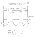
- FIG. 7 is a diagram showing the format of control entry 90 .
- Sequence Number 106 is available to keep track of the specific control entry.
- Function 108 determines the length of the control entry, because it determines the number of 32 bit words 110 – 112 required to define the function.
- the function code is an 8 bit number which decodes into 256 different numbers. Values 0, 7–16, and 33–255 are defined as invalid.
- the remaining defined function codes are as follows:
- FIG. 8 is a table showing structures that are allocated in memory as made by the XPC.
- FIG. 9 is a detailed diagram showing segment descriptor accessing.
- Segment Descriptor Pointer Table 114 consists of multiple 32-bit unsigned integer entries.
- Segment Descriptor Pointer Entry 118 consists of 32 words of 32 bits each. The first word is the test and set lock which is used to control access to the segment descriptors that hash to this entry. The remaining words point to up to eight entries within the Segment Descriptor Table, consisting of multiple 32-bit unsigned integers. Word 17 of Segment Descriptor Pointer Entry 116 is hash link 0 ( 122 ), word 19 is hash link 1 ( 124 ), and word 31 is hash link 7 ( 126 ).
- the file name associated with hash link 0 is File Identifier 130 occupying the first two words of the Segment Descriptor Table.
- the corresponding File Relative Segment Offset 132 is located in the next word.
- Word 9 is Next Segment Descriptor 134 which points to the next associated segment (i.e., File Identifier 142 ) as shown.
- File name associated with hash link 1 is File Identifier 136 .
- File Relative Segment Offset 138 provides the corresponding relative offset. Because there are no further-associated segment descriptors, Next Segment Descriptor 140 is null.
- File Relative Segment Offset 144 corresponds to File Identifier 142 .
- Next Segment Descriptor 146 which points to File Identifier 148 , located subsequent to extended area 128 .
- File Relative Segment Offset 150 corresponds thereto. There are no further associated segment descriptors so Next Segment Descriptor 152 is null.
- FIG. 10 is a detailed diagram showing lock entry accessing. It is via this locking system that the XPC (see also FIG. 1 ) maintains control of the shared database facilities.
- Lock Index Table consists of multiple 32-bit unsigned integer entries.
- Example 156 is Object Hast * 32 which points to Lock Index Entry 158 .
- Test and Set Lock 160 occupies the first word of Lock Index Entry 158 . It is used to control access to this lock list.
- Lock_List_Head 162 provides the address of the first lock entry that hashes to this location.
- Lock_List_Tail 164 supplies the address of the last lock entry that hashes to his location.
- Lock_List_Count 166 specifies the number of lock entries on this lock list.
- Lock Reverse Links 178 , 182 , 186 , and 190 supply the address of the previous lock entry in this lock list. Because it is associated with the first lock entry in the lock list, Lock Reverse Link 178 is Null.
- FIG. 11 is a detailed diagram of Process Entry accessing in accordance with the preferred mode of the present invention.
- Process Index Table 192 consists of multiple 32-bit unsigned integer entries.
- Sample entry 194 contains process hash * 32 which identifies the Process Index Entry shown.
- Test and Set Lock 196 is used to control access to this process list.
- PRP_List_Head 198 addresses the first Process Registration Packet 204 that hashes to this location.
- PRP_List_Tail 200 supplies the address of the last Process Registration Packet 246 that hashes to this location.
- PRP_List_Count 202 provides the number of Process Registration Packets on this process list.
- Process Registration Packets PRP 204 , 218 , 232 , and 246 , each consist of 16–32-bit unsigned integers.
- the first word is Process Identifier 206 , 220 , 234 , and 248 , respectively.
- the second word contains Host Identifier 210 , 224 , 238 , and 252 and Application Identifier 208 , 222 , 236 , and 250 , each of which define processing for the corresponding clustered instruction processor.
- Process Registration time 212 , 226 , 240 , and 254 is maintained in each of the Process Registration Packets. Part of the time is derived from the Windows operating system time and part from a code-maintained counter, which is sized to assure overall registration time uniqueness.
- Next PRP 214 , 228 , 242 , and 256 point to the next Process Registration Packet within the list. Because PRP Packet 246 is the last packet in the list, Next PRP is set to null. Similarly, Previous PRP 216 , 230 , 244 , and 260 each point to the next previous PRP packet. Because PRP Packet 204 is the first packet in the list, Previous PRP is set to null.
- FIG. 12 is a detailed view of the Inter-Host Cache (IHC) data structures.
- IHC Inter-Host Cache
- Two validity lists are shown in the example, with validity entries for sub-applications 1 : 1 and 2 : 1 .
- the sub-application entry is shown for sub-application 1 : 1 , and contains the Most_Recent_Age of validity entries for sub-application 1 : 1 .
- the Most_Recent_Age is used in conjunction with the sub-application size (SA_SIZE) to implement a MRU/LRU algorithm used to determine if the validity object is within the sub-application cache.
- SA_SIZE sub-application size
- Validity list entries which are outside of the LRU limit are removed whenever a validity operation encounters an ‘old’ entry. This is accomplished via a scan of the entire validity list after status is returned to the host.
- validity list ‘i’ contains two entries (A and B), one each for sub-application 1 : 1 and 2 : 1 .
- Validity list ‘j’ contains three entries (X, Y and Z), two for sub-application 1 : 1 and one for sub-application 2 : 1 .
- the sub-application entry is shown for sub-application 1 : 1 , having a Most_Recent_Age of 683 and SA_Size of 100, yielding a “validity age’ range of 584–683.
- the validity entries in validity list ‘j’ (entries X and Y) are both within the range and are therefore within the sub-application cache.
- the validity entry B in validity list ‘i’ for sub-application 1 : 1 is not within the range, and is therefore not with in the sub-application cache.
- the next IHC operation that references validity list ‘i’ will find and remove the ‘aged out’ entry.
- Sub-Application Table 262 contains multiple 32-bit unsigned integer entries. Entry 264 contains a Sub-Application Index * 16 which points to Sub-Application Entry 266 . The first word is Test and Set Lock 268 which controls access to the sub-application entry. MOST_RECENT_AGE 270 is the counter value for the most recently accessed validity entry in this sub-application. After its initial value of zero, the only operations allowed on this field are increments. SA_SIZE 272 is the number of validity entries for this sub-application. This is the value as seen by the hosts and not the actual number of validity entries that are on the validity lists.
- Validity Index Table 274 contains multiple 32-bit unsigned integer entries.
- a first sample entry 276 contains Validity Hash (i * 32 ) which points to Validity Index Entry 280 .
- a second sample entry 278 contains Validity Hash (j * 32 ) which points to Validity Index Entry 290 .
- Validity Index Entry 280 has a Test and Set Lock 282 which is used to control access to this validity list.
- VL_HEAD 284 supplies the address of the first validity entry (i.e., Validity Entry A 300 ) that hashes to his location.
- VL_TAIL 286 contains the address of the last validity entry (i.e., Validity Entry B 314 ) that hashes to this location.
- VL_ITEM_CNT 288 specifies the number of validity entries on this validity list.
- Validity Index Entry 290 has a Test and Set Lock 292 which is used to control access to this validity list.
- VL_HEAD 294 supplies the address of the first validity entry (i.e., Validity Entry X 328 ) that hashes to his location.
- VL_TAIL 296 contains the address of the last validity entry (i.e., Validity Entry Z 356 ) that hashes to this location.
- VL_ITEM_CNT 298 specifies the number of validity entries on this validity list.
- Each of Validity Entries A 300 , B 314 , X 328 , Y 342 , and Z 356 contains an Object Identifier (i.e., 302 , 316 , 330 , 344 , and 358 ); a forward link (i.e., VL_FWD_LINK 306 , 318 , 332 , 346 , and 360 ); a reverse link (i.e., VL_REV_LINK 308 , 320 , 334 , 348 , and 362 ); and an age (i.e., SA_VL_AGE 310 , 322 , 336 , 350 , and 364 ).
- an Object Identifier i.e., 302 , 316 , 330 , 344 , and 358
- a forward link i.e., VL_FWD_LINK 306 , 318 , 332 , 346 , and 360
- a reverse link i.
- FIG. 13 is detailed diagram showing the format of Validity Entry 370 with Refresh Pending Extension.
- Validity Entry 370 contains VL_FWD_LINK 374 and VL_REV_LINK 376 , as previously discussed.
- the validity entry i.e., Validity Entry 370
- VL_FWD_LINK 374 and VL_REV_LINK 376 are shown with five processes within the same sub-application in ‘refresh pending’ state.
- Refresh Pending Entry-Process A 378 shows that Process A was the first referenced for this validity entry.
- the order of the processes in the RP Extension entries i.e., entries 384 , 386 , 388 , and 390 ) indicates that the processes initially referenced the validity entry in the order of A-B-C-D-E. However, subsequent references to the same validity entry occurred in a different order.
- the ‘RP List Order’ 382 maintains an LRU/MRU list of the current processes in the Refresh Pending entries. In the example shown at detail 392 , process B referenced the validity entry most recently, whereas process D referenced the validity entry least recently (i.e., or oldest reference).
- the RP Extension is addressed by RP_Extension_Address 380 .
- FIG. 14 is a detailed diagram showing the messaging implementation.
- messages (represented by message buffers i 426 , j 430 , and k 434 ) reside on the ‘waiting message queue’ (WMQ), waiting for a wait-for-message (WFM) from each addressed host.
- WMQ waiting message queue
- WFM wait-for-message
- Message Control Table 394 points to Message Buffer i 426 via WMQ_HEAD 398 and to Message Buffer k 434 via WMQ_TAIL 400 .
- the three message buffers are internally linked via NEXT_MESSAGE 428 , 432 , and 436 .
- Messages (represented by Message Buffers x 438 and y 442 ) have been sent to the host(s) but have not yet been acknowledged, and both are members of the ‘sent message queue’ (SMQ).
- SMQ_HEAD 402 points to Message Buffer x 438 and SMQ_TAIL 404 points to Message Buffer y 442 .
- Message Buffer ‘x’ 438 belongs to the host corresponding to the shown head-of-host (HOH) entry, and Message Buffer ‘y’ 442 belongs to some other host.
- NEXT_MESSAGE 440 links the two message buffers in the sent message queue.
- the message buffers are shown as separate entries for purposes of clarity and are derived from the Message Buffers in the Head-of-Host entries.
- the collection of Message Buffers in a HOH entry 410 are known as a Host Message Buffer Queue (HMBQ).
- HMBQ Host Message Buffer Queue
- Message Buffer ‘x’ 438 resides within the Message Buffers 422 of the shown HOH entry 410 .
- a Head-of-Host Table (HOHT) 406 contains an entry for each of the 64 possible hosts, each table entry contains an array of active Wait-For-Message commands (WFMs), an array of Unacknowledged Messages (UAMs), and an array of message buffers.
- WFMs Wait-For-Message commands
- UAMs Unacknowledged Messages
- MCT Message Control Table
- FIG. 15 is a detailed diagram showing integration of the cluster/locking, caching, and mass storage accessing functions into a single platform.
- the OS 2200 host 446 communicates directly with the single platform incorporating the 2200 IOP 446 , 2200 Locking 448 , and 2200 Interhost Messaging 450 functionality as shown.
- Large I/O Cache 452 Windows Operating system and Device Drivers 454 , and the Standard Channel I/O Processor as shown.
- the present invention incorporates each of these elements into a single platform. Therefore, communication with Tape 456 , DVD 458 , and Disk 460 , via paths 462 , 464 , and 466 , respectively, is accomplished within the same hardware entity as is interfaced directly with OS 2200 Host 446 .
Abstract
Description
Claims (20)
Priority Applications (1)
| Application Number | Priority Date | Filing Date | Title |
|---|---|---|---|
| US10/346,458 US7043580B1 (en) | 2003-01-17 | 2003-01-17 | Cluster lock server: ability to support multiple standard and proprietary locking protocols |
Applications Claiming Priority (1)
| Application Number | Priority Date | Filing Date | Title |
|---|---|---|---|
| US10/346,458 US7043580B1 (en) | 2003-01-17 | 2003-01-17 | Cluster lock server: ability to support multiple standard and proprietary locking protocols |
Publications (1)
| Publication Number | Publication Date |
|---|---|
| US7043580B1 true US7043580B1 (en) | 2006-05-09 |
Family
ID=36272447
Family Applications (1)
| Application Number | Title | Priority Date | Filing Date |
|---|---|---|---|
| US10/346,458 Expired - Lifetime US7043580B1 (en) | 2003-01-17 | 2003-01-17 | Cluster lock server: ability to support multiple standard and proprietary locking protocols |
Country Status (1)
| Country | Link |
|---|---|
| US (1) | US7043580B1 (en) |
Cited By (4)
| Publication number | Priority date | Publication date | Assignee | Title |
|---|---|---|---|---|
| US20060190526A1 (en) * | 2005-02-22 | 2006-08-24 | Nextair Corporation | Wireless communication device use of application server applications |
| US8560662B2 (en) * | 2011-09-12 | 2013-10-15 | Microsoft Corporation | Locking system for cluster updates |
| US20130290584A1 (en) * | 2012-04-30 | 2013-10-31 | Futurewei Technologies, Inc. | Sequence-based process locking |
| US9170852B2 (en) | 2012-02-02 | 2015-10-27 | Microsoft Technology Licensing, Llc | Self-updating functionality in a distributed system |
Citations (9)
| Publication number | Priority date | Publication date | Assignee | Title |
|---|---|---|---|---|
| US5940826A (en) | 1997-01-07 | 1999-08-17 | Unisys Corporation | Dual XPCS for disaster recovery in multi-host computer complexes |
| US6151663A (en) * | 1994-12-28 | 2000-11-21 | Intel Corporation | Cluster controller for memory and data cache in a multiple cluster processing system |
| US6412079B1 (en) * | 1998-10-09 | 2002-06-25 | Openwave Systems Inc. | Server pool for clustered system |
| US20020161955A1 (en) * | 2001-04-27 | 2002-10-31 | Beukema Bruce Leroy | Atomic ownership change operation for input/output (I/O) bridge device in clustered computer system |
| US20030005080A1 (en) * | 2001-06-28 | 2003-01-02 | Watkins James S. | Systems and methods for accessing data |
| US20030018927A1 (en) * | 2001-07-23 | 2003-01-23 | Gadir Omar M.A. | High-availability cluster virtual server system |
| US6609213B1 (en) * | 2000-08-10 | 2003-08-19 | Dell Products, L.P. | Cluster-based system and method of recovery from server failures |
| US6675217B1 (en) * | 2000-07-06 | 2004-01-06 | Microsoft Corporation | Recovery of cluster consistency following failover |
| US6728896B1 (en) * | 2000-08-31 | 2004-04-27 | Unisys Corporation | Failover method of a simulated operating system in a clustered computing environment |
-
2003
- 2003-01-17 US US10/346,458 patent/US7043580B1/en not_active Expired - Lifetime
Patent Citations (9)
| Publication number | Priority date | Publication date | Assignee | Title |
|---|---|---|---|---|
| US6151663A (en) * | 1994-12-28 | 2000-11-21 | Intel Corporation | Cluster controller for memory and data cache in a multiple cluster processing system |
| US5940826A (en) | 1997-01-07 | 1999-08-17 | Unisys Corporation | Dual XPCS for disaster recovery in multi-host computer complexes |
| US6412079B1 (en) * | 1998-10-09 | 2002-06-25 | Openwave Systems Inc. | Server pool for clustered system |
| US6675217B1 (en) * | 2000-07-06 | 2004-01-06 | Microsoft Corporation | Recovery of cluster consistency following failover |
| US6609213B1 (en) * | 2000-08-10 | 2003-08-19 | Dell Products, L.P. | Cluster-based system and method of recovery from server failures |
| US6728896B1 (en) * | 2000-08-31 | 2004-04-27 | Unisys Corporation | Failover method of a simulated operating system in a clustered computing environment |
| US20020161955A1 (en) * | 2001-04-27 | 2002-10-31 | Beukema Bruce Leroy | Atomic ownership change operation for input/output (I/O) bridge device in clustered computer system |
| US20030005080A1 (en) * | 2001-06-28 | 2003-01-02 | Watkins James S. | Systems and methods for accessing data |
| US20030018927A1 (en) * | 2001-07-23 | 2003-01-23 | Gadir Omar M.A. | High-availability cluster virtual server system |
Cited By (9)
| Publication number | Priority date | Publication date | Assignee | Title |
|---|---|---|---|---|
| US20060190526A1 (en) * | 2005-02-22 | 2006-08-24 | Nextair Corporation | Wireless communication device use of application server applications |
| US7668937B2 (en) * | 2005-02-22 | 2010-02-23 | Research In Motion Limited | Wireless communication device use of application server applications |
| US20100106775A1 (en) * | 2005-02-22 | 2010-04-29 | Tim Neil | Wireless communication device use of application server applications |
| US20110087725A9 (en) * | 2005-02-22 | 2011-04-14 | Tim Neil | Wireless communication device use of application server applications |
| US8190712B2 (en) | 2005-02-22 | 2012-05-29 | Research In Motion Limited | Wireless communication device use of application server applications |
| US8560662B2 (en) * | 2011-09-12 | 2013-10-15 | Microsoft Corporation | Locking system for cluster updates |
| US9058237B2 (en) | 2011-09-12 | 2015-06-16 | Microsoft Technology Licensing, Llc | Cluster update system |
| US9170852B2 (en) | 2012-02-02 | 2015-10-27 | Microsoft Technology Licensing, Llc | Self-updating functionality in a distributed system |
| US20130290584A1 (en) * | 2012-04-30 | 2013-10-31 | Futurewei Technologies, Inc. | Sequence-based process locking |
Similar Documents
| Publication | Publication Date | Title |
|---|---|---|
| US9158779B2 (en) | Multi-node replication systems, devices and methods | |
| US7130924B2 (en) | System and method for synchronizing copies of data in a computer system | |
| KR100232247B1 (en) | Virtual shared disks with application-transparent recovery | |
| US5809527A (en) | Outboard file cache system | |
| US8825882B2 (en) | Method and apparatus for implementing high-performance, scaleable data processing and storage systems | |
| US6339793B1 (en) | Read/write data sharing of DASD data, including byte file system data, in a cluster of multiple data processing systems | |
| US5561809A (en) | In a multiprocessing system having a coupling facility, communicating messages between the processors and the coupling facility in either a synchronous operation or an asynchronous operation | |
| US6192514B1 (en) | Multicomputer system | |
| US5339427A (en) | Method and apparatus for distributed locking of shared data, employing a central coupling facility | |
| US6587921B2 (en) | Method and apparatus for cache synchronization in a clustered environment | |
| US7814065B2 (en) | Affinity-based recovery/failover in a cluster environment | |
| US6421787B1 (en) | Highly available cluster message passing facility | |
| EP0428006B1 (en) | Multilevel locking system and method | |
| US6081883A (en) | Processing system with dynamically allocatable buffer memory | |
| US6457098B1 (en) | Methods and apparatus for coordinating shared multiple raid controller access to common storage devices | |
| US7246255B1 (en) | Method for shortening the resynchronization time following failure in a computer system utilizing separate servers for redundancy | |
| US7181642B1 (en) | Method for distributing the processing among multiple synchronization paths in a computer system utilizing separate servers for redundancy | |
| JPH086854A (en) | Outboard-file-cache external processing complex | |
| JPH07101408B2 (en) | Method for operating a multiprocessor computer system and computer network | |
| US6424988B2 (en) | Multicomputer system | |
| WO1998028685A1 (en) | Coordinating shared access to common storage | |
| JPH02228744A (en) | Data processing system | |
| JP2017517064A (en) | System and method for supporting bypass domain model and proxy model and for updating service information for inter-domain message communication in a transaction middleware machine environment | |
| US7155638B1 (en) | Clustered computer system utilizing separate servers for redundancy in which the host computers are unaware of the usage of separate servers | |
| US6732137B1 (en) | Performance optimization for data sharing across batch sequential processes and on-line transaction processes |
Legal Events
| Date | Code | Title | Description |
|---|---|---|---|
| AS | Assignment |
Owner name: UNISYS CORPORATION, MINNESOTA Free format text: ASSIGNMENT OF ASSIGNORS INTEREST;ASSIGNORS:HEIDEMAN, MICHAEL J.;COOPER, THOMAS P.;SMITH, RONALD Q.;REEL/FRAME:013687/0442 Effective date: 20021220 |
|
| STCF | Information on status: patent grant |
Free format text: PATENTED CASE |
|
| AS | Assignment |
Owner name: UNISYS CORPORATION, PENNSYLVANIA Free format text: RELEASE BY SECURED PARTY;ASSIGNOR:CITIBANK, N.A.;REEL/FRAME:023312/0044 Effective date: 20090601 Owner name: UNISYS HOLDING CORPORATION, DELAWARE Free format text: RELEASE BY SECURED PARTY;ASSIGNOR:CITIBANK, N.A.;REEL/FRAME:023312/0044 Effective date: 20090601 Owner name: UNISYS CORPORATION,PENNSYLVANIA Free format text: RELEASE BY SECURED PARTY;ASSIGNOR:CITIBANK, N.A.;REEL/FRAME:023312/0044 Effective date: 20090601 Owner name: UNISYS HOLDING CORPORATION,DELAWARE Free format text: RELEASE BY SECURED PARTY;ASSIGNOR:CITIBANK, N.A.;REEL/FRAME:023312/0044 Effective date: 20090601 |
|
| AS | Assignment |
Owner name: UNISYS CORPORATION, PENNSYLVANIA Free format text: RELEASE BY SECURED PARTY;ASSIGNOR:CITIBANK, N.A.;REEL/FRAME:023263/0631 Effective date: 20090601 Owner name: UNISYS HOLDING CORPORATION, DELAWARE Free format text: RELEASE BY SECURED PARTY;ASSIGNOR:CITIBANK, N.A.;REEL/FRAME:023263/0631 Effective date: 20090601 Owner name: UNISYS CORPORATION,PENNSYLVANIA Free format text: RELEASE BY SECURED PARTY;ASSIGNOR:CITIBANK, N.A.;REEL/FRAME:023263/0631 Effective date: 20090601 Owner name: UNISYS HOLDING CORPORATION,DELAWARE Free format text: RELEASE BY SECURED PARTY;ASSIGNOR:CITIBANK, N.A.;REEL/FRAME:023263/0631 Effective date: 20090601 |
|
| AS | Assignment |
Owner name: DEUTSCHE BANK TRUST COMPANY AMERICAS, AS COLLATERA Free format text: PATENT SECURITY AGREEMENT (PRIORITY LIEN);ASSIGNOR:UNISYS CORPORATION;REEL/FRAME:023355/0001 Effective date: 20090731 |
|
| AS | Assignment |
Owner name: DEUTSCHE BANK TRUST COMPANY AMERICAS, AS COLLATERA Free format text: PATENT SECURITY AGREEMENT (JUNIOR LIEN);ASSIGNOR:UNISYS CORPORATION;REEL/FRAME:023364/0098 Effective date: 20090731 |
|
| FPAY | Fee payment |
Year of fee payment: 4 |
|
| AS | Assignment |
Owner name: GENERAL ELECTRIC CAPITAL CORPORATION, AS AGENT, IL Free format text: SECURITY AGREEMENT;ASSIGNOR:UNISYS CORPORATION;REEL/FRAME:026509/0001 Effective date: 20110623 |
|
| AS | Assignment |
Owner name: UNISYS CORPORATION, PENNSYLVANIA Free format text: RELEASE BY SECURED PARTY;ASSIGNOR:DEUTSCHE BANK TRUST COMPANY;REEL/FRAME:030004/0619 Effective date: 20121127 |
|
| AS | Assignment |
Owner name: UNISYS CORPORATION, PENNSYLVANIA Free format text: RELEASE BY SECURED PARTY;ASSIGNOR:DEUTSCHE BANK TRUST COMPANY AMERICAS, AS COLLATERAL TRUSTEE;REEL/FRAME:030082/0545 Effective date: 20121127 |
|
| FPAY | Fee payment |
Year of fee payment: 8 |
|
| AS | Assignment |
Owner name: WELLS FARGO BANK, NATIONAL ASSOCIATION, AS COLLATE Free format text: PATENT SECURITY AGREEMENT;ASSIGNOR:UNISYS CORPORATION;REEL/FRAME:042354/0001 Effective date: 20170417 Owner name: WELLS FARGO BANK, NATIONAL ASSOCIATION, AS COLLATERAL TRUSTEE, NEW YORK Free format text: PATENT SECURITY AGREEMENT;ASSIGNOR:UNISYS CORPORATION;REEL/FRAME:042354/0001 Effective date: 20170417 |
|
| AS | Assignment |
Owner name: JPMORGAN CHASE BANK, N.A., AS ADMINISTRATIVE AGENT, ILLINOIS Free format text: SECURITY INTEREST;ASSIGNOR:UNISYS CORPORATION;REEL/FRAME:044144/0081 Effective date: 20171005 Owner name: JPMORGAN CHASE BANK, N.A., AS ADMINISTRATIVE AGENT Free format text: SECURITY INTEREST;ASSIGNOR:UNISYS CORPORATION;REEL/FRAME:044144/0081 Effective date: 20171005 |
|
| AS | Assignment |
Owner name: UNISYS CORPORATION, PENNSYLVANIA Free format text: RELEASE BY SECURED PARTY;ASSIGNOR:WELLS FARGO BANK, NATIONAL ASSOCIATION (SUCCESSOR TO GENERAL ELECTRIC CAPITAL CORPORATION);REEL/FRAME:044416/0358 Effective date: 20171005 |
|
| MAFP | Maintenance fee payment |
Free format text: PAYMENT OF MAINTENANCE FEE, 12TH YEAR, LARGE ENTITY (ORIGINAL EVENT CODE: M1553) Year of fee payment: 12 |
|
| AS | Assignment |
Owner name: UNISYS CORPORATION, PENNSYLVANIA Free format text: RELEASE BY SECURED PARTY;ASSIGNOR:WELLS FARGO BANK, NATIONAL ASSOCIATION;REEL/FRAME:054231/0496 Effective date: 20200319 |