US6922465B1 - Method and system for reporting events in telecommunication networks - Google Patents
Method and system for reporting events in telecommunication networks Download PDFInfo
- Publication number
- US6922465B1 US6922465B1 US09/418,436 US41843699A US6922465B1 US 6922465 B1 US6922465 B1 US 6922465B1 US 41843699 A US41843699 A US 41843699A US 6922465 B1 US6922465 B1 US 6922465B1
- Authority
- US
- United States
- Prior art keywords
- subscriber
- network
- node
- call
- messages
- Prior art date
- Legal status (The legal status is an assumption and is not a legal conclusion. Google has not performed a legal analysis and makes no representation as to the accuracy of the status listed.)
- Expired - Fee Related
Links
Images


Classifications
-
- H—ELECTRICITY
- H04—ELECTRIC COMMUNICATION TECHNIQUE
- H04M—TELEPHONIC COMMUNICATION
- H04M3/00—Automatic or semi-automatic exchanges
- H04M3/42—Systems providing special services or facilities to subscribers
- H04M3/42391—Systems providing special services or facilities to subscribers where the subscribers are hearing-impaired persons, e.g. telephone devices for the deaf
-
- H—ELECTRICITY
- H04—ELECTRIC COMMUNICATION TECHNIQUE
- H04M—TELEPHONIC COMMUNICATION
- H04M3/00—Automatic or semi-automatic exchanges
- H04M3/42—Systems providing special services or facilities to subscribers
- H04M3/487—Arrangements for providing information services, e.g. recorded voice services or time announcements
-
- H—ELECTRICITY
- H04—ELECTRIC COMMUNICATION TECHNIQUE
- H04M—TELEPHONIC COMMUNICATION
- H04M2203/00—Aspects of automatic or semi-automatic exchanges
- H04M2203/20—Aspects of automatic or semi-automatic exchanges related to features of supplementary services
- H04M2203/2061—Language aspects
-
- H—ELECTRICITY
- H04—ELECTRIC COMMUNICATION TECHNIQUE
- H04Q—SELECTING
- H04Q2213/00—Indexing scheme relating to selecting arrangements in general and for multiplex systems
- H04Q2213/13058—Interrupt request
-
- H—ELECTRICITY
- H04—ELECTRIC COMMUNICATION TECHNIQUE
- H04Q—SELECTING
- H04Q2213/00—Indexing scheme relating to selecting arrangements in general and for multiplex systems
- H04Q2213/13141—Hunting for free outlet, circuit or channel
-
- H—ELECTRICITY
- H04—ELECTRIC COMMUNICATION TECHNIQUE
- H04Q—SELECTING
- H04Q2213/00—Indexing scheme relating to selecting arrangements in general and for multiplex systems
- H04Q2213/13162—Fault indication and localisation
-
- H—ELECTRICITY
- H04—ELECTRIC COMMUNICATION TECHNIQUE
- H04Q—SELECTING
- H04Q2213/00—Indexing scheme relating to selecting arrangements in general and for multiplex systems
- H04Q2213/13288—Closed user groups, CUG
-
- H—ELECTRICITY
- H04—ELECTRIC COMMUNICATION TECHNIQUE
- H04Q—SELECTING
- H04Q2213/00—Indexing scheme relating to selecting arrangements in general and for multiplex systems
- H04Q2213/13396—Signaling in general, in-band signalling
Definitions
- the present invention relates to telecommunication networks and, more particularly, to a method and system for reporting events to subscribers in telecommunication networks.
- Telecommunication networks use various signaling systems for establishing calls between subscribers. At times, however, the networks may detect certain states or events that would prevent the networks from establishing calls between subscribers. These events may include, for example, when a called directory number is out of service, network lines are busy or down, a switching node experiences a problem, etc. In such instances, the networks instead report the detected events to the subscribers by playing prerecorded audible messages.
- a switching node local to the calling subscriber receives a call request from the calling subscriber's device.
- the switching node then sends a route request to a signaling node in the network to determine a route for the call. If the signaling node determines a route, the signaling node returns to the switching node the directory number of the next node in the network through which the call must be routed. Otherwise, if the signaling node detects that the call cannot be established or routed such as when the called subscriber's directory number is out of service, the signaling node returns an error code to the switching node. The switching node then notifies the subscriber that the requested call cannot be established by playing a prerecorded audible message corresponding to the error code.
- audible messages may be sufficient for reporting events to subscribers who use plain ordinary telephone service (POTS) telephone sets, such messages are not universally recognizable by all subscriber devices. For example, consider a subscriber who uses a telecommunications device for the deaf (TDD) to place calls to other subscribers in the network. When the network plays an audible message to report an event, neither the subscriber nor the TDD device would be able to recognize the message. Similarly, an application running in a desktop computer for dialing into, for example, a local Internet Service Provider (ISP) system cannot recognize audible messages received from the network or present such messages in a form that is recognizable to a subscriber.
- ISP Internet Service Provider
- subscriber devices used in automotive telemetric or remote reading applications.
- subscriber devices send and receive data from remote systems by automatically placing calls over the existing networks.
- these subscriber devices cannot process the audible messages that are reported by the networks, they cannot provide the subscriber with informative information as to the cause of most communication failures.
- these subscriber devices cannot automatically take corrective actions in response to most communication failures. Corrective actions may include, for example, redialing a directory number when network lines are busy or dialing a different directory number when a previously dialed directory number is temporarily out of service.
- Corrective actions may include, for example, redialing a directory number when network lines are busy or dialing a different directory number when a previously dialed directory number is temporarily out of service.
- Methods and systems consistent with the present invention report network events to subscribers in a plurality of formats and languages depending upon the particular subscriber group to which a subscriber belongs.
- Such methods and systems identify a subscriber's group, determine a directory number associated with the identified group and the detected event, and report to the subscriber a message associated with the determined directory number.
- a switching node is configured with a trigger that designates a signaling node in the network for routing call requests received by the switching node from subscribers in the network.
- the designated signaling node is configured with a directory number mapping table that includes a plurality of predetermined directory numbers indexed according to events, which when detected are reported to the calling subscribers such as, when a subscriber's directory number is out of service, network lines are busy or out of service, etc. These predetermined directory numbers are further indexed according to subscriber groups in the network.
- the predetermined directory numbers are selected so that they terminate at a message node such as, a messaging system, in the network, where a plurality of stored messages are associated with the predetermined directory numbers, respectively.
- messages may be stored in a plurality of formats and languages such as, voice, data, telecommunications for the deaf (TDD), English, Spanish, etc. depending upon the particular subscriber groups in the network.
- a switching node When a switching node receives a request for a call from a calling subscriber to a called subscriber, the switching node invokes the trigger configured therein to identify the signaling node designated for routing calls from the calling subscriber and sends a route request to the identified signaling node. While processing the route request, if the signaling node detects an event that should be reported to the calling subscriber, the signaling node identifies the subscriber group associated with the calling subscriber. The signaling node then selects a directory number from the directory number mapping table based on the detected event and the identified subscriber group and returns the selected directory number to the switching node. Based on the directory number received from the signaling node, the switching node establishes a call between the calling subscriber and the message node, where a message associated with the directory number is executed.
- the network reports the detected event in a format and language that the calling subscriber or its device can recognize.
- an event such as, an error that must be reported to the calling subscriber
- that event is reported in a TDD format to a calling subscriber using a TDD device
- the same event is reported in a voice format to a calling subscriber using a POTS telephone set.
- events are reported in English to a calling subscriber whose subscriber group profile indicates that events should be reported in English
- the same events are reported in Spanish to a calling subscriber whose subscriber group profile indicates that events should be reported in Spanish.
- FIG. 1 is a block diagram of a telecommunications network, in accordance with methods and systems consistent with the invention
- FIG. 2 is a block diagram of a switching node in a telecommunications network, in accordance with methods and systems consistent with the invention
- FIG. 3 is a block diagram of a trigger table in a switching node, in accordance with methods and systems consistent with the invention
- FIG. 4 is a block diagram of a signaling node in a telecommunications network, in accordance with methods and systems consistent with the invention
- FIG. 5 is a block diagram of a directory number mapping table in a signaling node, in accordance with methods and systems consistent with the invention
- FIG. 6 is a block diagram of a message node in a telecommunications network, in accordance with methods and systems consistent with the invention.
- FIG. 7 is a block diagram of a network interface module in a message node, in accordance with methods and systems consistent with the invention.
- FIG. 8 is a flow chart of the steps performed by a call processing module in a switching node, in accordance with methods and systems consistent with the invention.
- FIG. 9 is a flow chart of the steps performed by a call routing module in a signaling node, in accordance with methods and systems consistent with the invention.
- a network is configured such that network events are reported to subscribers in a plurality of formats and languages depending upon the particular subscriber group to which a subscriber belongs.
- a switching node in the network receives a call request from a subscriber, a trigger in the switching node is invoked to identify a designated signaling node for routing the call.
- the switching node then sends a route request to the signaling node. If during processing of the route request the signaling node detects an event that should be reported to the subscriber, the signaling node identifies the subscriber group associated with the subscriber.
- the signaling node selects from a directory mapping table a directory number associated with the identified subscriber group and the detected event and returns the selected directory number to the switching node.
- Switching node then establishes the call to the message node, where a message associated with the determined directory number is executed.
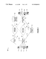
- FIG. 1 shows a block diagram of a telecommunications network 100 , in accordance with methods and systems consistent with the invention.
- network 100 comprises switching nodes 110 and 120 , a signaling node 130 , a subscriber services database 140 , a message node 150 , a switching network 160 , and a signaling network 170 .
- Switching node 110 connects via links 181 , 182 , and 183 to message node 150 , switching network 160 , and signaling node 130 , respectively.
- Links 181 and 182 include, for example, N lines 181 1 - 181 N and 182 1 - 182 N (not shown), respectively.
- Switching node 110 also connects via local loops to a telephone 111 , telecommunications for the deaf (TDD) device 112 , facsimile machine 113 , and a desktop computer 114 .
- TDD deaf
- Switching node 110 may include, for example, a 5ESSTM, DMS-100TM (or DMS-200TM), GTD-5TM, or an EWSDTM switching system manufactured by Lucent Technologies, Inc., Nortel Networks Corporation, AGCS, and Siemens, respectively. As explained below in detail, switching node 110 is configured to request routing information from signaling node 130 when switching node 110 receives call requests from telephone 111 , TDD device 112 , facsimile machine 113 , and desktop computer 114 .
- switching node 120 connects via links 184 , 185 , and 186 to message node 150 , switching network 160 , and signaling network 170 , respectively.
- Switching node 120 also connects via local loops to a telephone 121 , TDD device 122 , facsimile machine 123 , and a desktop computer 124 .
- Signaling node 130 interfaces subscriber services database 140 via signaling network 170 .
- Signaling node 130 may include a Service Control Point (SCP) such as, AI-NETTM, Integrated Service Control Point (ISCPTM), or Service BuilderTM equipment/software manufactured or provided by Lucent Technologies, Inc., Telcordia Technologies, Inc., and Nortel Networks Corporation, respectively.
- SCP Service Control Point
- AI-NETTM AI-NETTM
- ISCPTM Integrated Service Control Point
- Subscriber services database 140 stores information about subscriber services and may include, for example, a line information database (LIDB), call management services database (CMSDB), and/or business services database (BSDB).
- LIDB line information database
- CMSDB call management services database
- BSDB business services database
- the LIDB, CMSDB, and BSDB are defined in Bellcore (now Telcordia Technologies, Inc.) publication TR-NWT-001244, “Supplemental Service Control Point (SCP).”
- Message node 150 may include, for example, a messaging system, which includes messages in a plurality of formats such as, voice, data, and TDD, and in a plurality of languages such as, English, Spanish, French, etc.
- message node 150 may be a workstation, which includes a plurality of stored messages and a bank of modems for receiving calls from switching nodes 110 and 120 and switching network 160 .
- Switching network 160 and signaling network 170 may include, for example, a Public Switched Telephone Network (PSTN) and a Signaling System 7 (SS7) network, respectively.
- PSTN Public Switched Telephone Network
- SS7 Signaling System 7
- FIG. 2 is a block diagram of switching node 110 , in accordance with methods and systems consistent with the invention.
- Switching node 110 comprises a processor 200 , which connects via bus 210 to a memory 220 , a secondary storage 230 , a peripheral module 240 , a signaling module 250 , and input terminal 260 , and an output terminal 270 .
- Memory 220 includes a call processing module 222 , an operating system 224 , and a trigger table 226 .
- Call processing module 222 includes data and software executed by processor 200 for establishing, maintaining, and terminating calls between subscribers in network 100 .
- Operating system 224 includes data and software executed by processor 200 for non-switching functions, which include, for example, task scheduling and processor interrupt handling.
- trigger table 226 includes entries that are used to intercept call requests in switching node 110 and to identify the associated signaling nodes such as, signaling node 130 , for routing the requested calls in network 100 .
- Secondary storage 230 includes a computer readable medium such as a disk drive and a tape drive. From the tape drive, software and data may be loaded onto the disk drive, which can then be copied into memory 220 . Similarly, software and data in memory 220 may be copied onto the disk drive, which can then be loaded onto the tape drive.
- a computer readable medium such as a disk drive and a tape drive. From the tape drive, software and data may be loaded onto the disk drive, which can then be copied into memory 220 . Similarly, software and data in memory 220 may be copied onto the disk drive, which can then be loaded onto the tape drive.
- Peripheral interface module 240 interfaces with links 181 and 182 , which connect switching node 110 to message node 150 and switching network 160 , respectively.
- Signaling interface module 250 transmits to and receives from signaling node 130 signaling information such as, Advanced Intelligent Network (AIN) messages. For example, signaling interface module 250 converts signaling information generated by call processing module 222 into AIN messages and transmits the messages to signaling node 130 . Likewise, signaling interface module 250 receives AIN messages from signaling node 130 and converts the messages into an internal format for processing by call processing module 222 .
- AIN Advanced Intelligent Network
- Input terminal 260 may include an input device such as, a keyboard, and output terminal 270 may include a display device.
- FIG. 3 is a block diagram of trigger table 226 , in accordance with methods and systems consistent with the invention.
- Trigger table 226 includes K predetermined triggers shown as entries 300 1 - 300 K , where each entry includes an index field 301 and an identifier field 302 .
- an index field 301 may include a 3, 6, or 10 digit string such as, an area code, an area code and an office code, or a directory number.
- PODP triggers are described in AIN 0.1 standards
- TR-NWT-001284 Advanced Intelligent Network (AIN) 0.1 Switching System Generic Requirements, Issue 1 (March 1992)
- TR-NWT-001285 Advanced Intelligent Network (AIN) 0.1 Service Control Point (SCP) Application Protocol Interface Requirements, Issue 1 (March 1992), both of which are incorporated herein by reference.
- an index field 301 may include any sequence of digits.
- SDS triggers are described in AIN 0.2 standards GR-1298-CORE: AIN SSP, AINGR: Switching Systems (A Module Of AINGR, FR-15), Issue 4 (September 1997) and GR-1299-CORE: AINGR: Switch—Service Control Point (SCP)/Adjunct Interface (A Module Of AINGR, FR-15), Issue 4 (September 1997), both of which are incorporated herein by reference.
- An identifier field 302 includes a numeric string that identifies a signaling node associated with a calling subscriber's directory number whose area code, area code and office code, or directory number matches the associated an index field 301 in trigger table 226 .
- trigger table 226 may be configured to include a trigger entry 300 K , where index field 301 K includes the area code associated with telephone 111 and identifier field 302 K includes a translation type/global title address (TT/GTA) associated with signaling node 130 . The TT/GTA may then be communicated to a signaling transfer point (STP) in network 100 for determining a point code associated with signaling node 130 .
- identifier field 302 K may include a point code associated with signaling node 130 , which may be used by switching node 110 to directly identify signaling node 130 .
- FIG. 4 is a block diagram of signaling node 130 , in accordance with methods and systems consistent with the invention.
- Signaling node 130 comprises a processor 400 , which connects via a bus 410 to a memory 420 , a secondary storage 430 , a signaling interface module 440 , an input terminal 450 , and an output terminal 460 .
- Memory 420 includes a call routing module 422 , an operating system 424 , and a directory number (DN) mapping table 426 .
- Call routing module 422 includes data and software executed by processor 400 for communicating with subscriber services database 140 via signaling network 170 .
- Secondary storage 430 includes a computer readable medium such as a disk drive and a tape drive. From the tape drive, software and data may be loaded onto the disk drive, which can then be copied into memory 420 . Similarly, software and data in memory 420 may be copied onto the disk drive, which can then be loaded onto the tape drive.
- a computer readable medium such as a disk drive and a tape drive.
- Signaling interface module 440 transmits to and receives from switching node 110 and signaling network 170 signaling information such as, AIN messages. For example, signaling interface module 440 converts signaling information generated by call routing module 422 into AIN messages and transmits the messages to switching node 110 and signaling network 170 . Likewise, signaling interface module 440 receives AIN messages from switching node 110 and signaling network 170 and converts the messages into an internal format for processing by call routing module 422 .
- Input terminal 450 may include an input device such as, a keyboard, and output terminal 460 may include a display device.
- FIG. 5 is a block diagram of DN mapping table 426 , in accordance with methods and systems consistent with the invention.
- DN mapping table 426 includes L entries 500 1 - 500 L , where each entry includes an index field 501 and a directory number field 502 .
- An index field 501 may include, for example, an event code and a subscriber group identifier, which identify an event and a subscriber group, respectively.
- a directory number field 502 includes a directory number that terminates at message node 150 .
- an administrator may configure DN mapping table 426 such that each event code and subscriber group identifier combination is associated with a unique directory number. The administrator may select each event code and subscriber group identifier combination so that subscriber devices namely, telephone 111 , TDD device 112 , and desktop computer 114 , each receives from message node 150 messages that can be processed by the subscriber devices.
- a subscriber dials a directory number and network 100 detects an event such as, an error in network 100 that must be reported to the subscriber, that event is reported in a TDD format to a subscriber using TDD device 112 , whereas the same event is reported in a voice format to a subscriber using telephone 111 .
- events are reported in English to a subscriber whose subscriber group profile indicates that events should be reported in English, whereas the same events are reported in Spanish to a subscriber whose subscriber group profile indicates that events should be reported in Spanish.
- network 100 is configured to selectively report messages in different formats and languages, depending upon the particular subscriber group associated with a calling subscriber and the particular event detected by network 100 .
- FIG. 6 is a block diagram of message node 150 , in accordance with methods and systems consistent with the invention.
- Message node 150 comprises a processor 600 , which connects via bus 610 to a memory 620 , a network interface module 630 , a secondary storage 640 , an input device 650 , and an output device 660 .
- Message node 150 may include a messaging system such as, Octel 250 manufactured by Lucent Technologies.
- message node 150 may include a computer that includes a VFX/PCI board manufactured by Dialogic, an Intel Company. Each port in the VFX/PCI board may be connected to a line in links 181 , 184 , and 188 .
- Memory 620 includes a message server 622 and an operating system 624 .
- Message server 622 includes data and software executed by processor 600 for executing M messages 645 1 - 645 M stored in secondary storage 640 .
- Operating system 624 includes data and software executed by processor 600 for managing tasks and processor interrupts.
- message server 622 In response to an interrupt initiated by network interface module 630 , message server 622 loads into memory 620 one of messages 645 1 - 645 M that corresponds to the port on which a call is detected in network interface module 630 .
- links 181 , 184 , and 188 are provisioned as Direct Inward Dialing (DID) links
- message server 622 loads into memory 620 one of messages 645 1 - 645 M that corresponds to a sequence of digits (e.g. a portion or all digits) of a directory number included in the detected call.
- DID Direct Inward Dialing
- Message server 622 then executes or plays the message loaded into memory 620 . After executing or playing the message, message server 622 signals network interface module 630 to terminate the call.
- Secondary storage 640 stores messages 645 1 - 645 M in a plurality of formats such as, voice, data, TDD, and in a plurality of languages such as, English, Spanish, French, etc.
- An administrator stores messages 645 1 - 645 M in secondary storage 640 such that each message is associated with a unique port in network interface module 630 .
- Input device 650 may include an input device such as, a keyboard, and output device 660 may include a display device.
- Network interface module 630 which connects to links 181 , 184 , and 188 , includes hardware and software for processing calls that arrive on links 181 , 184 , and 188 .
- FIG. 7 is a block diagram of network interface module 630 , in accordance with methods and systems consistent with the invention.
- Network interface module 630 includes a processor 700 , which connects via bus 710 to a memory 720 , 3 ⁇ N ports 730 1 - 730 N , 740 1 - 740 N , and 750 1 - 750 N .
- Ports 730 1 - 730 N connect to lines 181 1 - 181 N , respectively; ports 740 1 - 740 N connect to lines 184 1 - 184 N , respectively; and ports 750 1 - 750 N connect to lines 188 1 - 188 N , respectively.
- links 181 , 184 , and 188 may be provisioned as DID links such that calls detected at ports 730 1 - 730 N , 740 1 - 740 N , and 750 1 - 750 N include a portion (e.g., the last few digits) or all of the digits of the directory numbers associated with the calls.
- Memory 720 includes a call processing module 722 , which includes data and software executed by processor 700 for processing calls that arrive on lines 181 1 - 181 N , 184 1 - 184 N , and 188 1 - 188 N .
- Call processing module 722 monitors ports 730 1 - 730 N , 740 1 - 740 N , and 750 1 - 750 N , detects calls that arrive on lines 181 1 - 181 N , 184 1 - 184 N , and 188 1 - 188 N , and transmits an off-hook signal to network 100 when a call is detected on any of the lines 181 1 - 188 N , 184 1 - 184 N , and 188 1 - 188 N .
- call processing module 722 initiates an interrupt in processor 600 to notify message server 622 as to the port on which a call is detected.
- FIG. 8 is a flow chart of the steps performed by call processing module 222 in switching node 110 , in accordance with methods and systems consistent with the invention.
- a calling subscriber dials a directory number from, for example, telephone 111 (shown in FIG. 1 ) to a called subscriber that uses telephone 122 .
- call processing module 222 receives a call request from telephone 111 (step 800 ).
- Call processing module 222 then invokes a trigger configured in trigger table 226 based on the directory number of the calling subscriber (step 810 ).
- call processing module 222 invokes a trigger whose index matches a sequence of digits in the calling subscriber's directory number such as, the area code, a combination of the area code and office code, the calling subscriber's full directory number, or any other sequence of digits.
- call processing module 222 requests a route from signaling node 130 by sending, for example, an AIN info_analyze message whose parameters include the called subscriber's directory number and the calling subscriber's directory number (step 820 ). Call processing module 222 then suspends further processing of the call until it receives a response from signaling node 130 (step 830 ).
- the response from signaling node 130 may include, for example, an AIN info_analyze_response message that includes as one of its parameters a directory number to which call processing module 222 must route the call. If signaling node 130 detects an event that must be reported to the calling subscriber such as, when the called subscriber's directory number is out of service, network 100 lines are busy, or a segment of network 100 is down, signaling node 130 returns in the info_analyze_response message a directory number that terminates at message node 150 . Otherwise, signaling node 130 returns the directory number of the next node in network 100 that must process the call request in order to establish the call between calling subscriber telephone 111 and called subscriber telephone 121 .
- Call processing module 222 then establishes a call using the directory number received from signaling node 130 (step 840 ). If the directory number terminates at message node 150 , message node 150 answers the call and executes or plays a message associated with that directory number. Finally, call processing module 222 terminates the call when the calling subscriber telephone 111 or message node 150 requests a disconnect (step 850 ).
- FIG. 9 is a flow chart of the steps performed by a call routing module 422 in signaling node 130 , in accordance with methods and systems consistent with the invention.
- call routing module 422 receives from switching node 110 a request for a route from the calling subscriber to the called subscriber (step 900 ).
- call routing module 422 may receive an AIN info_analyze message whose parameters include the called subscriber's directory number and the calling subscriber's directory number.
- call routing module 422 determines whether network 100 can establish the call (step 910 ). If call routing module 422 determines that network 100 can establish the call, call routing module 422 determines the directory number of the next node in network 100 that must process the call (step 920 ). Call routing module 422 then sends to switching node 110 the determined directory number in an AIN info_analyze_response message (step 950 ).
- call routing module 422 determines that network 100 cannot establish the call or detects an event that must be reported to the calling subscriber such as, when the called subscriber's directory number is out of service or network 100 links are busy. Call routing module 422 determines the event code associated with that event. Call routing module 422 then queries subscriber service database 140 , which may include, for example, a LIDB database, to determine the subscriber group identifier associated with the calling subscriber (step 930 ).
- subscriber service database 140 which may include, for example, a LIDB database
- call routing module 422 After determining the subscriber group identifier of the calling subscriber, call routing module 422 selects from DN mapping table 426 an entry whose index field 501 matches, for example, the event code and the subscriber group identifier (step 940 ). Call routing module 422 then reads the directory number in the directory number field 502 of the selected entry and sends the directory number to switching node 10 in an AIN info_analyze_response message (step 950 ).
- signaling node 130 has identified an appropriate message in message node 150 for reporting the detected event to the calling subscriber.
Abstract
Description
Claims (38)
Priority Applications (4)
| Application Number | Priority Date | Filing Date | Title |
|---|---|---|---|
| US09/418,436 US6922465B1 (en) | 1999-10-14 | 1999-10-14 | Method and system for reporting events in telecommunication networks |
| US09/692,804 US7039164B1 (en) | 1999-10-14 | 2000-10-20 | Method and system for reporting events in telecommunication networks |
| US11/320,325 US7548611B2 (en) | 1999-10-14 | 2005-12-29 | Method and system for reporting events in telecommunication networks |
| US12/467,829 US7929669B2 (en) | 1999-10-14 | 2009-05-18 | Method and system for reporting events in telecommunication networks |
Applications Claiming Priority (1)
| Application Number | Priority Date | Filing Date | Title |
|---|---|---|---|
| US09/418,436 US6922465B1 (en) | 1999-10-14 | 1999-10-14 | Method and system for reporting events in telecommunication networks |
Related Child Applications (1)
| Application Number | Title | Priority Date | Filing Date |
|---|---|---|---|
| US09/692,804 Continuation-In-Part US7039164B1 (en) | 1999-10-14 | 2000-10-20 | Method and system for reporting events in telecommunication networks |
Publications (1)
| Publication Number | Publication Date |
|---|---|
| US6922465B1 true US6922465B1 (en) | 2005-07-26 |
Family
ID=34748704
Family Applications (1)
| Application Number | Title | Priority Date | Filing Date |
|---|---|---|---|
| US09/418,436 Expired - Fee Related US6922465B1 (en) | 1999-10-14 | 1999-10-14 | Method and system for reporting events in telecommunication networks |
Country Status (1)
| Country | Link |
|---|---|
| US (1) | US6922465B1 (en) |
Cited By (13)
| Publication number | Priority date | Publication date | Assignee | Title |
|---|---|---|---|---|
| US20030061052A1 (en) * | 2001-09-26 | 2003-03-27 | Richard Breuer | Method of switching between dialog systems |
| US20050185657A1 (en) * | 2004-02-24 | 2005-08-25 | James Karanassos | Methods and apparatus for managing voice over IP telephony |
| US20060003689A1 (en) * | 2004-05-17 | 2006-01-05 | Pointshot Wireless Inc. | Qualitative determination of system health in centralized network management |
| US20070195752A1 (en) * | 2006-02-22 | 2007-08-23 | Lucent Technologies Inc. | System and method for handling call redirection and multi call destination failures |
| US20080285558A1 (en) * | 2007-05-14 | 2008-11-20 | Yuwen Wu | Reporting events from multiple ws-enabled devices |
| US7929669B2 (en) | 1999-10-14 | 2011-04-19 | Gte Wireless Incorporated | Method and system for reporting events in telecommunication networks |
| US20120087368A1 (en) * | 2010-10-07 | 2012-04-12 | Pulse Networks | System and method for best value routing |
| US20130114467A1 (en) * | 2000-12-07 | 2013-05-09 | Rockstar Consortium Us Lp | Providing Calling Party Information in a Request to Establish a Call Session |
| US20170358296A1 (en) | 2016-06-13 | 2017-12-14 | Google Inc. | Escalation to a human operator |
| US10827064B2 (en) | 2016-06-13 | 2020-11-03 | Google Llc | Automated call requests with status updates |
| US11158321B2 (en) | 2019-09-24 | 2021-10-26 | Google Llc | Automated calling system |
| US11303749B1 (en) | 2020-10-06 | 2022-04-12 | Google Llc | Automatic navigation of an interactive voice response (IVR) tree on behalf of human user(s) |
| US11468893B2 (en) | 2019-05-06 | 2022-10-11 | Google Llc | Automated calling system |
Citations (9)
| Publication number | Priority date | Publication date | Assignee | Title |
|---|---|---|---|---|
| US4191860A (en) | 1978-07-13 | 1980-03-04 | Bell Telephone Laboratories, Incorporated | Data base communication call processing method |
| US4756020A (en) | 1985-08-30 | 1988-07-05 | American Telephone And Telegraph Company, At&T Bell Laboratories | Method and apparatus for disallowing the extension of a call through a network |
| US5353331A (en) | 1992-03-05 | 1994-10-04 | Bell Atlantic Network Services, Inc. | Personal communications service using wireline/wireless integration |
| US5440615A (en) * | 1992-03-31 | 1995-08-08 | At&T Corp. | Language selection for voice messaging system |
| US5574904A (en) | 1990-01-19 | 1996-11-12 | Fujitsu Limited | Database management system in an intelligent network using a common request data format |
| US5583920A (en) * | 1992-04-17 | 1996-12-10 | Bell Atlantic | Intelligent peripheral in video dial tone network |
| US6088429A (en) * | 1998-04-07 | 2000-07-11 | Mumps Audiofax, Inc. | Interactive telephony system |
| US6327363B1 (en) * | 1998-04-17 | 2001-12-04 | Mci Worldcom, Inc. | Method and system for automated customer services |
| US6535596B1 (en) * | 1997-09-29 | 2003-03-18 | Lucent Technologies Inc. | Call processing system utilizing subscriber services and preferences |
-
1999
- 1999-10-14 US US09/418,436 patent/US6922465B1/en not_active Expired - Fee Related
Patent Citations (13)
| Publication number | Priority date | Publication date | Assignee | Title |
|---|---|---|---|---|
| US4191860A (en) | 1978-07-13 | 1980-03-04 | Bell Telephone Laboratories, Incorporated | Data base communication call processing method |
| US4756020A (en) | 1985-08-30 | 1988-07-05 | American Telephone And Telegraph Company, At&T Bell Laboratories | Method and apparatus for disallowing the extension of a call through a network |
| US5574904A (en) | 1990-01-19 | 1996-11-12 | Fujitsu Limited | Database management system in an intelligent network using a common request data format |
| US5664005A (en) | 1992-03-05 | 1997-09-02 | Bell Atlantic Network Services, Inc. | Personal communications service using wireline/wireless integration |
| US5353331A (en) | 1992-03-05 | 1994-10-04 | Bell Atlantic Network Services, Inc. | Personal communications service using wireline/wireless integration |
| US5506887A (en) | 1992-03-05 | 1996-04-09 | Bell Atlantic Network Services, Inc. | Personal communications service using wireline/wireless integration |
| US5758281A (en) | 1992-03-05 | 1998-05-26 | Bell Atlantic Network Services, Inc. | Personal communications service using wireline/wireless integration |
| US5610972A (en) | 1992-03-05 | 1997-03-11 | Bell Atlantic Network Services, Inc. | Personal communications service using wireline/wireless integration |
| US5440615A (en) * | 1992-03-31 | 1995-08-08 | At&T Corp. | Language selection for voice messaging system |
| US5583920A (en) * | 1992-04-17 | 1996-12-10 | Bell Atlantic | Intelligent peripheral in video dial tone network |
| US6535596B1 (en) * | 1997-09-29 | 2003-03-18 | Lucent Technologies Inc. | Call processing system utilizing subscriber services and preferences |
| US6088429A (en) * | 1998-04-07 | 2000-07-11 | Mumps Audiofax, Inc. | Interactive telephony system |
| US6327363B1 (en) * | 1998-04-17 | 2001-12-04 | Mci Worldcom, Inc. | Method and system for automated customer services |
Cited By (34)
| Publication number | Priority date | Publication date | Assignee | Title |
|---|---|---|---|---|
| US7929669B2 (en) | 1999-10-14 | 2011-04-19 | Gte Wireless Incorporated | Method and system for reporting events in telecommunication networks |
| US20130114467A1 (en) * | 2000-12-07 | 2013-05-09 | Rockstar Consortium Us Lp | Providing Calling Party Information in a Request to Establish a Call Session |
| US9008294B2 (en) * | 2000-12-07 | 2015-04-14 | Spherix Incorporated | Providing calling party information in a request to establish a call session |
| US7343290B2 (en) * | 2001-09-26 | 2008-03-11 | Nuance Communications, Inc. | System and method of switching between dialog systems with separate dedicated communication units |
| US20030061052A1 (en) * | 2001-09-26 | 2003-03-27 | Richard Breuer | Method of switching between dialog systems |
| US20050185657A1 (en) * | 2004-02-24 | 2005-08-25 | James Karanassos | Methods and apparatus for managing voice over IP telephony |
| US8638779B2 (en) * | 2004-02-24 | 2014-01-28 | Itxc Ip Holdings Sarl | Methods and apparatus for managing voice over IP telephony |
| US20060003689A1 (en) * | 2004-05-17 | 2006-01-05 | Pointshot Wireless Inc. | Qualitative determination of system health in centralized network management |
| US20070195752A1 (en) * | 2006-02-22 | 2007-08-23 | Lucent Technologies Inc. | System and method for handling call redirection and multi call destination failures |
| US20080285558A1 (en) * | 2007-05-14 | 2008-11-20 | Yuwen Wu | Reporting events from multiple ws-enabled devices |
| US8135822B2 (en) * | 2007-05-14 | 2012-03-13 | Ricoh Company, Ltd. | Reporting events from multiple WS-enabled devices |
| US20120087368A1 (en) * | 2010-10-07 | 2012-04-12 | Pulse Networks | System and method for best value routing |
| US9118593B2 (en) * | 2010-10-07 | 2015-08-25 | Enghouse Networks Limited | System and method for best value routing |
| US10542143B2 (en) | 2016-06-13 | 2020-01-21 | Google Llc | Automated call requests with status updates |
| US11012560B2 (en) | 2016-06-13 | 2021-05-18 | Google Llc | Automated call requests with status updates |
| US20190306314A1 (en) | 2016-06-13 | 2019-10-03 | Google Llc | Automated call requests with status updates |
| US20170358296A1 (en) | 2016-06-13 | 2017-12-14 | Google Inc. | Escalation to a human operator |
| US10560575B2 (en) | 2016-06-13 | 2020-02-11 | Google Llc | Escalation to a human operator |
| US10574816B2 (en) | 2016-06-13 | 2020-02-25 | Google Llc | Automated call requests with status updates |
| US10582052B2 (en) | 2016-06-13 | 2020-03-03 | Google Llc | Automated call requests with status updates |
| US10721356B2 (en) * | 2016-06-13 | 2020-07-21 | Google Llc | Dynamic initiation of automated call |
| US10827064B2 (en) | 2016-06-13 | 2020-11-03 | Google Llc | Automated call requests with status updates |
| US10893141B2 (en) | 2016-06-13 | 2021-01-12 | Google Llc | Automated call requests with status updates |
| US10917522B2 (en) | 2016-06-13 | 2021-02-09 | Google Llc | Automated call requests with status updates |
| US20180227418A1 (en) | 2016-06-13 | 2018-08-09 | Google Llc | Automated call requests with status updates |
| US11936810B2 (en) | 2016-06-13 | 2024-03-19 | Google Llc | Automated call requests with status updates |
| US11563850B2 (en) | 2016-06-13 | 2023-01-24 | Google Llc | Automated call requests with status updates |
| US11468893B2 (en) | 2019-05-06 | 2022-10-11 | Google Llc | Automated calling system |
| US11495233B2 (en) | 2019-09-24 | 2022-11-08 | Google Llc | Automated calling system |
| US11741966B2 (en) | 2019-09-24 | 2023-08-29 | Google Llc | Automated calling system |
| US11158321B2 (en) | 2019-09-24 | 2021-10-26 | Google Llc | Automated calling system |
| US20220201119A1 (en) | 2020-10-06 | 2022-06-23 | Google Llc | Automatic navigation of an interactive voice response (ivr) tree on behalf of human user(s) |
| US11303749B1 (en) | 2020-10-06 | 2022-04-12 | Google Llc | Automatic navigation of an interactive voice response (IVR) tree on behalf of human user(s) |
| US11843718B2 (en) | 2020-10-06 | 2023-12-12 | Google Llc | Automatic navigation of an interactive voice response (IVR) tree on behalf of human user(s) |
Similar Documents
| Publication | Publication Date | Title |
|---|---|---|
| US7548611B2 (en) | Method and system for reporting events in telecommunication networks | |
| US7555109B2 (en) | System and method for caller control of a distinctive ring | |
| US6697475B1 (en) | System and method for implementing an end office switch with enhanced functionality using an operating system independent distributed self-contained dynamic logic system | |
| US6718026B1 (en) | Call forwarding methods and apparatus | |
| US7616747B2 (en) | Telephone network control system and method | |
| US6301349B1 (en) | Method and system to connect an unanswered forwarded communication directly to a voice mail service | |
| US20070019624A1 (en) | Trunk and switch architecture for providing switched-circuit connections to on-line data services | |
| US5659605A (en) | Method and apparatus for providing soft dial tone using office equipment designators | |
| US6035028A (en) | Telecommunications network architecture enabling local services resale in a legacy network | |
| KR20010022744A (en) | Management of calling name delivery in telephone networks providing for telephone number portability | |
| US6487412B1 (en) | Method and system for routing calls to wireless directory numbers in a network | |
| EP1033026A1 (en) | System, method and apparatus for direct voice mail access and blocking | |
| US6922465B1 (en) | Method and system for reporting events in telecommunication networks | |
| US20040032864A1 (en) | Centralized service control for a telecommunication system | |
| CA2251848C (en) | System and method for activation of an enhanced telecommunication service | |
| US6055232A (en) | Telecommunications network architecture deploying intelligent network services in a legacy network | |
| AU2485799A (en) | Local switch | |
| EP0924919A2 (en) | System and method for centrex translation | |
| KR20010090478A (en) | Intelligent-networked telecommunication system which strategically creates and employs service-dependent pseudo calling line identities to eliminate redundant billing errors | |
| US6526137B1 (en) | System and method of performing forced default routing of calls | |
| CA2283851C (en) | System and method for providing local number portability service | |
| US6208727B1 (en) | Method of alerting apartment residents to the arrival of visitors | |
| US7394897B1 (en) | Method and system for routing service calls made from resold lines | |
| CA2359394C (en) | Method and system for reporting events in telecommunication networks | |
| US7664247B1 (en) | Methods and apparatus for integrating automatic route selection with AIN services |
Legal Events
| Date | Code | Title | Description |
|---|---|---|---|
| AS | Assignment |
Owner name: GTE WIRELESS SERVICE CORPORATION, GEORGIA Free format text: ASSIGNMENT OF ASSIGNORS INTEREST;ASSIGNOR:HOWE, WALTER WESLEY;REEL/FRAME:010322/0788 Effective date: 19991011 |
|
| AS | Assignment |
Owner name: GTE WIRELESS INCORPORATED, NEW JERSEY Free format text: MERGER;ASSIGNOR:GTE WIRELESS SERVICE CORPORATION;REEL/FRAME:021709/0699 Effective date: 20031114 |
|
| FPAY | Fee payment |
Year of fee payment: 4 |
|
| FPAY | Fee payment |
Year of fee payment: 8 |
|
| REMI | Maintenance fee reminder mailed | ||
| LAPS | Lapse for failure to pay maintenance fees |
Free format text: PATENT EXPIRED FOR FAILURE TO PAY MAINTENANCE FEES (ORIGINAL EVENT CODE: EXP.) |
|
| STCH | Information on status: patent discontinuation |
Free format text: PATENT EXPIRED DUE TO NONPAYMENT OF MAINTENANCE FEES UNDER 37 CFR 1.362 |
|
| FP | Lapsed due to failure to pay maintenance fee |
Effective date: 20170726 |
|
| AS | Assignment |
Owner name: GTE WIRELESS LLC, NEW JERSEY Free format text: CERTIFICATE OF CONVERSION;ASSIGNOR:GTE WIRELESS INCORPORATED;REEL/FRAME:055264/0275 Effective date: 20160628 |