US6842175B1 - Tools for interacting with virtual environments - Google Patents
Tools for interacting with virtual environments Download PDFInfo
- Publication number
- US6842175B1 US6842175B1 US09/959,087 US95908701A US6842175B1 US 6842175 B1 US6842175 B1 US 6842175B1 US 95908701 A US95908701 A US 95908701A US 6842175 B1 US6842175 B1 US 6842175B1
- Authority
- US
- United States
- Prior art keywords
- virtual environment
- set forth
- environment system
- virtual
- system set
- Prior art date
- Legal status (The legal status is an assumption and is not a legal conclusion. Google has not performed a legal analysis and makes no representation as to the accuracy of the status listed.)
- Expired - Lifetime
Links
Images


Classifications
-
- G—PHYSICS
- G06—COMPUTING; CALCULATING OR COUNTING
- G06F—ELECTRIC DIGITAL DATA PROCESSING
- G06F3/00—Input arrangements for transferring data to be processed into a form capable of being handled by the computer; Output arrangements for transferring data from processing unit to output unit, e.g. interface arrangements
- G06F3/01—Input arrangements or combined input and output arrangements for interaction between user and computer
- G06F3/011—Arrangements for interaction with the human body, e.g. for user immersion in virtual reality
-
- G—PHYSICS
- G06—COMPUTING; CALCULATING OR COUNTING
- G06F—ELECTRIC DIGITAL DATA PROCESSING
- G06F3/00—Input arrangements for transferring data to be processed into a form capable of being handled by the computer; Output arrangements for transferring data from processing unit to output unit, e.g. interface arrangements
- G06F3/01—Input arrangements or combined input and output arrangements for interaction between user and computer
- G06F3/017—Gesture based interaction, e.g. based on a set of recognized hand gestures
-
- G—PHYSICS
- G06—COMPUTING; CALCULATING OR COUNTING
- G06F—ELECTRIC DIGITAL DATA PROCESSING
- G06F3/00—Input arrangements for transferring data to be processed into a form capable of being handled by the computer; Output arrangements for transferring data from processing unit to output unit, e.g. interface arrangements
- G06F3/01—Input arrangements or combined input and output arrangements for interaction between user and computer
- G06F3/03—Arrangements for converting the position or the displacement of a member into a coded form
- G06F3/033—Pointing devices displaced or positioned by the user, e.g. mice, trackballs, pens or joysticks; Accessories therefor
- G06F3/0346—Pointing devices displaced or positioned by the user, e.g. mice, trackballs, pens or joysticks; Accessories therefor with detection of the device orientation or free movement in a 3D space, e.g. 3D mice, 6-DOF [six degrees of freedom] pointers using gyroscopes, accelerometers or tilt-sensors
-
- G—PHYSICS
- G06—COMPUTING; CALCULATING OR COUNTING
- G06F—ELECTRIC DIGITAL DATA PROCESSING
- G06F3/00—Input arrangements for transferring data to be processed into a form capable of being handled by the computer; Output arrangements for transferring data from processing unit to output unit, e.g. interface arrangements
- G06F3/01—Input arrangements or combined input and output arrangements for interaction between user and computer
- G06F3/048—Interaction techniques based on graphical user interfaces [GUI]
- G06F3/0487—Interaction techniques based on graphical user interfaces [GUI] using specific features provided by the input device, e.g. functions controlled by the rotation of a mouse with dual sensing arrangements, or of the nature of the input device, e.g. tap gestures based on pressure sensed by a digitiser
- G06F3/0488—Interaction techniques based on graphical user interfaces [GUI] using specific features provided by the input device, e.g. functions controlled by the rotation of a mouse with dual sensing arrangements, or of the nature of the input device, e.g. tap gestures based on pressure sensed by a digitiser using a touch-screen or digitiser, e.g. input of commands through traced gestures
- G06F3/04883—Interaction techniques based on graphical user interfaces [GUI] using specific features provided by the input device, e.g. functions controlled by the rotation of a mouse with dual sensing arrangements, or of the nature of the input device, e.g. tap gestures based on pressure sensed by a digitiser using a touch-screen or digitiser, e.g. input of commands through traced gestures for inputting data by handwriting, e.g. gesture or text
Definitions
- the invention relates generally to tools by means of which users of an interactive environment may interact with the environment and more specifically to tools for interactively manipulating objects belonging to a virtual environment.
- the virtual table a workbench-like back-projection system.
- Stereoscopic rendering allows representations of objects being worked on by the designer to appear as if they were floating in space above the table, permitting the designer to grab them, move them, and otherwise manipulate them in the virtual reality produced by the table.
- the virtual table seems perfectly suited as a virtual environment for interactive product design. The designer can either start with 2D sketches on the tabletop and then successively extrude them into 3D space or work directly in 3D from the beginning.
- the mere size of the table allows for intuitive, gesture-based interaction of the user's hand in the space above the virtual environment that appears on the tabletop.
- the virtual table as an interactive media—combines the strengths of conventional drawing boards, current CAD systems and interactive virtual environments; hence, the virtual table has the potential to make the CAD workplace into a 3D workspace.
- 265-272 describes the use of a pad to display a miniature representation of the virtual environment
- the user can look at the miniature representation from a point of view different from that from which the user is looking at the full-sized virtual environment.
- the user can also us a pointing device to select and manipulate items on either the miniature representation or the full-sized virtual environment, with manipulations in the one being reflected in the other. If the user's position in the full-sized virtual environment is recorded on the miniature representation, the miniature representation serves as a map.
- the miniature representation may work as a “magic lens” to show aspects of the virtual environment that are not visible in the full-sized version.
- Angus, et al. disclose the use of a virtual tool called a paddle to interact with a virtual environment in their paper, Ian G. Angus, et al. “Embedding the 2D Interaction Metaphor in a Real 3D Virtual Environment, Proceedings of IS&T/SPIE's Electronic Imaging Symposium, 1995.
- the paddle is hand-held and has three real buttons.
- the virtual environment knows the position of the paddle and of a pointing device, and projects 2-D representations onto the paddle's opaque surface. The user can then employ the buttons and the pointing device to interact with the display on the paddle.
- One use of the paddle is to give the user of the virtual environment a 2-D map of the environment with the user's current position in the environment marked on the map. The user employs the map to locate him or herself within the virtual environment and to navigate to other locations in the environment.
- the invention provides tools for working with the virtual environment that are themselves part of the virtual environment.
- the user employs a device to view a portion of the virtual environment and the virtual environment system responds to the position and orientation of the device and the direction and point of view of the user by producing a modification of the portion as required for the tool.
- the device is a mirror and the virtual environment system responds to the mirror's position and orientation and the given direction and point of view by modifying the portion of the virtual environment that is reflected in the mirror.
- the reflected portion may be modified to show the virtual environment as it would be seen from the direction and point of view that is the reflection of the given direction and point of view in the mirror, so that it appears to the viewer in the same fashion as a real environment seen through a mirror.
- the reflected portion may also be used as a “Magic lens” to show a different view of the virtual environment, for example, an X-ray view. What is seen may further depend on which side of the mirror is being used. Ray tools may be used with the mirror by simply pointing the ray tool at the desired point in the reflection in the mirror.
- the device is transflective, that is, the user can simultaneously see objects through the device and objects reflected on the device.
- the objects seen through the device belong to a physical space and the objects reflected on the device belong to a reflection space.
- the virtual environment system Given the location and orientation of the device, the direction and point of view of the user's eyes, and a location in the physical space, the virtual environment system can define the reflection space so that it exactly overlaps the physical space and can define a portion of the virtual environment so that the reflection of the portion in the device appears at the given location in the physical space.
- the technique can be used to deal with occlusion of the virtual environment by a real object or to augment a real object with objects created by the virtual environment.
- the device may simply be a handle.
- the virtual environment system uses the given direction and point of view and the device position and orientation to determine where the image of a tool controlled by the handle appears in the virtual environment.
- the handle may be attached to a transparent component such as a transparent tube or a transparent panel.
- the extent of the tool's image is determined by the extent of the transparent component and to the user, the transparent component and the tool's image appear to merge, that is, the tool appears to be whatever the portion of the virtual environment that the user sees through the transparent component shows.
- a transparent tube may appear in the virtual environment as a stylus, a net, a trowel, a knife, or a saw and may be used to perform corresponding operations on the virtual environment.
- the transparent panel similarly merges with whatever the portion of the virtual environment viewed through the panel shows, and may therefore be as polymorphic as the transparent tube.
- the device may have two or more sides, with the modification of the portion depending on which side is used to view the virtual environment
- Useful modifications include ones in which the portion of the virtual environment is modified to appear as though it were viewed through a transparent panel, ones in which the portion is modified to function as a “magic lens”, and ones where a “snapshot” can be made of the portion and the device used to move the “snapshot” to another part of the virtual environment.
- the portion can also be used to select an object in the virtual environment, either by being moved over the object or by sweeping through the volume of the virtual environment occupied by the object.
- the portion may also be context sensitive in that its appearance changes in response to the selection of a particular object.
- the portion may further include one or more objects that move with the portion, and the device may be used with a selection device.
- the objects that move with the portion may include objects to be placed in the virtual environment or objects that have been taken from the virtual environment and placed in the portion.
- the objects that move with the portion may further include representations of operations to be performed on selected objects of the virtual environment. Examples of such representations are buttons and sliders. Among the operations is changing the manner in which the virtual environment system modifies the portion.
- the portion thus functions as a tool palette for working with the virtual environment.
- the tool palette is context sensitive in that the representations depend on the mode of operation of the portion and the object being operated on.
- the selection device may be transparent and the virtual environment system may use the position and orientation of the selection device and the given direction and point of view to produce an image of the selection device in the portion.
- the image may contain a visual representation of the operation presently being performed using the selection device.
- the selection device may be a stylus and the device itself may be a transparent panel.
- the virtual environment system may respond to movements of an end of the stylus on or near the transparent panel by making corresponding marks in the portion of the virtual environment.
- the virtual environment system may further include a gesture manager which interprets the movements of the end of the stylus as gestures indicating objects, operations, or letters and/or numbers.
- the device that is used to view the portion of the virtual environment may operate in either the reflective or transparent modes just described, with the mode of operation being determined by the orientation of the device relative to the virtual environment.
- the device that is used to view the portion may be fixed or movable relative to the virtual environment, as may be the given direction and point of view. Where both are movable, the given direction and point of view may be those of the eyes of a user of the virtual environment system and the device may be held in the user's hand. Modes of operation of the device may depend on the position of the device relative to the virtual environment or on separate mode inputs.
- FIG. 1 is an overview of an implementation of the invention in a virtual table
- FIG. 2 shows pad image 125 and pen image 127 as they appear when used as a palette tool
- FIG. 3 shows pad image 125 and pen image 127 as they appear when used as a first “through the plane tool”
- FIG. 4 shows pad image 125 and pen image 127 as they appear when used as a second “through the plane” tool
- FIG. 5 shows the geometry of object selection in tool 401 ;
- FIG. 6 shows operations performed by means of gestures written on the transparent pad
- FIG. 7 shows an “x-ray” pad image
- FIG. 8 shows the optics of the foil used in the reflective pad
- FIG. 9 shows how the angle of the transparent pad relative to the virtual table surface determines whether it is transparent or reflective
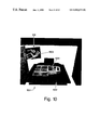
- FIG. 10 shows how the transparent pad can be used in reflective mode to examine a portion of the virtual environment that is otherwise not visible to the user
- FIG. 11 shows how the transparent pad may be used to capture a snapshot
- FIG. 12 shows a state diagram for the transparent pad when used to capture 3-D snapshots
- FIG. 13 shows projected pad 125 being used to select items in the virtual environment by sweeping through the virtual environment
- FIG. 14 shows the use of gestures to create objects in the virtual environment and to control the objects
- FIG. 15 shows the gestures used to create objects in a preferred embodiment
- FIG. 16 shows the gestures used to control objects and change modes in a preferred embodiment
- FIG. 17 shows how the portion of the virtual environment that is reflected in a mirror is determined
- FIG. 18 shows how ray pointing devices may be used with a mirror to manipulate a virtual environment reflected in the mirror
- FIG. 19 is an overview of virtual reality system program 109 ;
- FIG. 20 shows a portion of the technique used to determine whether the pad is operating in transparent or reflective mode
- FIG. 21 shows how a transflective panel may be used with a virtual environment to produce reflections of virtual objects that appear to belong to a physical space
- FIG. 22 shows how the transflective panel may be used to prevent a virtual object from being occluded by a physical object
- FIG. 23 shows how the transflective panel may be used to augment a physical object with a virtual object.
- Reference numbers in the drawing have three or more digits: the two right-hand digits are reference numbers in the drawing indicated by the remaining digits. Thus, an item with the reference number 203 first appears as item 203 in FIG. 2 .
- FIG. 1 Overview of the Pad and Pen Interface: FIG. 1
- the pad and pen interface of the invention employs a transparent pad and a large, pen-shaped plastic tube that functions as a pen and is further equipped with a button that is used in the same fashion as a mouse button to activate an object selected by the pen.
- the interface is used with a virtual table, but can be advantageously employed in any virtual reality system that uses back projection to create at least part of the virtual environment.
- FIG. 1 shows a system 101 for creating a virtual environment on a virtual table 111 in which the pad and pen interface of the invention is employed.
- Processor 103 is executing a virtual reality system program 109 that creates stereoscopic images of a virtual environment. The stereoscopic images are back-projected onto virtual table 111 .
- a user of virtual table 111 views the images through LCD shutter glasses 117 .
- the images appear to the user as a three-dimensional virtual environment.
- Shutter glasses 121 have a magnetic tracker attached to them which tracks the postion and orientation of the shutter glasses, and by that means, the postion and orientation of the user's eyes. Any other kind of 6DOF tracker could be used as well.
- the postition and orientation are input ( 115 ) to processing unit 105 and virtual reality system program 109 uses the position and orientation information to determine the point of view and viewing direction from which the user is viewing the virtual environment. It then uses the point of view and viewing direction to produce stereoscopic images of the virtual reality that show the virtual reality as it would be seen from the point of view and viewing direction indicated by the position and orientation information.
- Projected image 125 of transparent pad 123 may be transparent, or it may function as a “magic lens” to show a view of the virtual environment that is different from what is seen outside the area of projected image 125 . Projected image 125 may further appear to carry tools and objects that can be used in manipulating the virtual environment. Projected image 127 of pen 121 will further include a cursor at the pen's point. When the user looks at projected pad 125 through transparent pad 123 , projected object 129 appears to be on transparent pad 123 , and when real pen 121 is touching transparent pad 123 , projected pen image 127 appears to be touching projected pad 125 . By moving real pen 121 on transparent pad 123 , the user can thus touch and manipulate projected object 129 on projected pad 125 .
- System 101 thus unifies several previously isolated approaches to 3D user-interface design, such as two-handed interaction and the use of multiple coordinate systems.
- Our interface supports the following important features:
- pad image 125 which takes on many forms; the image 127 of tube 121 remains always a pen.
- Image 127 can, however, be just as polymorphic as pad image 125 : it can be the image of a pen, the image of a paint brush, the image of a net with a handle, and so on and so forth.
- both pad 123 and pen 121 can be reduced to handles: system 101 uses the position and orientation information from the handle and from shutter glasses 117 together with parameters about the size and type of tool to make an image of the tool at the proper position in the virtual environment.
- the handles are hidden by the user's hand and consequently need not be transparent.
- the handles could also have forms corresponding to the forms of the handles with real tools. For instance, the handle for a tool in the virtual environment whose real-world equivalent is two-handed can be two-handed.
- the advantage of using a real transparent pen and a real transparent panel instead of just handles is, of course, that the real transparent pen and panel are as polymorphic as handles by themselves, but also provide the user with tactile feedback.
- a preferred embodiment of system 101 uses the Baron Virtual Table produced by the Barco Group as its display device.
- This device offers a 53′′ ⁇ 40′′ display screen built into a table surface.
- the display is produced by a Indigo2TM Maximum Impact workstation manufactured by Silicon Graphics, Incorporated.
- transparent pad 123 is an 8′′ ⁇ 10′′ Plexiglas® acrylic plastic sheet and pen 121 is a large, transparent, pen-shaped plastic tube with a button.
- Both props and the shutter glasses in the preferred embodiment are equipped with 6DOF (six degrees of freedom) Flock of Birds® trackers made by Ascension Technology Corporation, for position and orientation tracking.
- the material for the pen and pad was also selected for minimal reflectivity, so that with dimmed light—the usual setup for working with the virtual table—the props become almost invisible. While they retain their tactile property, in the user's perception they are replaced by the projected pad 125 and projected pen 127 produced by the virtual table.
- Our observations and informal user studies indicate that virtual objects can even appear floating above pad 123 's surface, and that conflicting depth cues resulting from such scenarios are not perceived as disturbing. Conflicts occur only if virtual objects protrude from the outline of the prop as seen by the user because of the depth discontinuity. The most severe problem is occlusion from the user's hands. Graphical elements on pad 123 are placed in a way so that such occlusions are minimized, but they can never be completely avoided.
- the pen was chosen to be relatively large to provide room for graphics displayed inside the pen. In that way, the pen also provides visual feedback by e.g., displaying the tool it is currently associated with. So far, however, we have made only basic use of this capability and have instead focused on the pad as a carrier for the user interface.
- virtual reality system program 109 is based on the Studierstube software framework described in D. Schmalumble, A. Fuhrmann, Z. Szalavári, M. Gerckenz: “Studierstube”—An Environment for Collaboration in Augmented Reality. Extended abstract appeared Proc. of Collaborative Virtual Environments '96, Nottingham, UK, Sep. 19-20, 1996. Full paper in: Virtual Reality-Systems, Development and Applications, Vol. 3, No. 1, pp. 3749, 1998. Studierstube is realized as a collection of C++ classes that extend the Open Inventor toolkit, described at P. Strauss and R. Carey: An Object Oriented 3D Graphics Toolkit.
- Open Inventor's rich graphical environment approach allows rapid prototyping of new interaction styles, typically in the form of Open Inventor node kits.
- Tracker data is delivered to the application via an engine class, which forks a lightweight thread to decouple graphics and I/O.
- Off-axis stereo rendering on the VT is performed by a special custom viewer class.
- Studierstube extends Open Inventor's event system to process 3D (i.e., true 6DOF) events, which is necessary for choreographing complex 3D interactions like the ones described in this paper.
- the iv file format which includes our custom classes, allows convenient scripting of most of an application's properties, in particular the scene's geometry. Consequently very little application-specific C++ code—mostly in the form of event callbacks—was necessary.
- the Responsive Workbench A Virtual Work Environment IEEE Computer, 28(7):42-48, 1995.
- the space above the table is digitized using the tracker as a probe, with a wooden frame as a reference for correct real-world coordinates.
- the function represented by the set of samples is then numerically inverted and used at run-time as a look-up table to correct for systematic errors in the measurements.
- Window tools The rendering of window tools generally follows the method proposed in J. Viega, M. Conway, G. Williams, and R Pausch: 3D Magic Lenses. In Proceedings of ACM UIST'96, pages 51-58. ACM, 1996, except that it uses hardware stencil planes. After a preparation step, rendering of the world “behind the window” is performed inside the stencil mask created in the previous step, with a clipping plane coincident with the window polygon. Before rendering of the remaining scene proceeds, the window polygon is rendered again, but only the Z-buffer is modified. This step prevents geometric primitives of the remaining scene from protruding into the window. For a more detailed explanation, see D. Schmalumble, G. Schaufler: Sewing Virtual Worlds Together With SEAMS: A Mechanism to Construct Large Scale Virtual Environments. Technical Report TR-186-2-87-11, Vienna University of Technology, 1998.
- a way of using user interface props to interact with a virtual environment is termed in the following a metaphor.
- one such metaphor is the palette: projected pad 125 carries tools and controls that the user can employ to interact with the virtual environment.
- the metaphors for which the transparent pad and pen can be employed are the following:
- FIG. 2 shows transparent pad image 125 and pen image 127 when the two are being used according to a palette metaphor 201 .
- the transparent pad and pen are being used with a virtual reality program that generates a virtual environment for use in large-scale landscaping or town planning.
- Pad image 125 includes
- buttons 203 indicating objects such as buildings that can be placed in the virtual environment
- buttons 205 indicating tools that can be used to manipulate objects in the virtual environment.
- Button 209 is an exit button; it is used to exit from the application program being controlled by the transparent pad and pen.
- the user moves pen 121 on pad 123 until the cursor at the tip of pen image is within a button on pad image 125 and then presses the button on pen 121 to select the button on pad image 125 . As shown in FIG.
- a painting tool (indicated by the image of a painter's palette) has been selected and virtual reality program 109 has responded to the selection by making image 125 into a tool for defining a color. It has done this by adding images of sliders 207 to image 125 . These sliders control the amount of red, green, and blue in the color being defined, and are manipulated by placing pen 121 in a position on pad 123 such that the cursor on its image 127 touches a slider 207 in image 125 and then moving pen 121 in the direction that the slider 207 is to move. Virtual reality program 109 responds by moving the slider as indicated by pen 121 and changing the color being defined to agree with the movement of the slider.
- pad image 125 corresponding to transparent pad 123 resembles the dialog boxes used in desktop system GUIs in that it groups various application controls such as buttons, sliders, dials etc. Since transparent pad 123 is hand-held, it is always in convenient reach for the user, which is an advantage if working on different areas of the table. It is easy to remember where the controls are, and transparent pad 123 can even be put aside temporarily without causing confusion.
- the basic mode of our sample landscaping application is object placement.
- the pad serves as an object browser presenting a collection of objects to select from.
- the user then moves pen 121 in a fashion such that projected pen 120 appears to drag objects from pad image 125 and drop them into the virtual environment via direct 3D manipulation.
- Additional controls some implemented as space-saving pop-up button bar—allow the user to scale, colorize, and delete objects.
- 2D controls and 3D direct manipulation naturally blend as the pad represents a 2D surface similar to many real-world control containers in other application areas (e.g., a remote control, a radio, a dishwasher's front panel).
- image 125 when it is being used according to palette metaphor 201 is that it is context sensitive; it contains only those tools which are relevant to a particular situation in which it is being used.
- tools 205 include a selection tool for selecting an object in the virtual environment, and when an object has been selected, the buttons and tools on image 125 are those that are relevant to that object.
- Another interesting property is the multiple surfaces of reference with which the user simultaneously interacts. The user can thus select a representation of an object 203 from image 125 and use pen image 127 to drag the representation from pad image 125 to a location in the virtual environment and add it to the virtual environment. We make further use of these multiple surfaces of reference with the window and through-the-plane tools.
- pad image 125 may operate in modes in which it is transparent, i.e., the virtual environment may be seen through pad image 125 , allows the development of yet another class of user interface tools that we call through-the-plane tools. With these tools, pad image 125 is used to select an object in the virtual environment and the tools that are carried on pad image 125 are used to operate on the selected object
- the first tool is a context sensitive information and manipulation dialog, shown in FIG. 3 .
- pad image 125 When pad image 125 is being used as a tool 301 , pad image 305 has cross-hairs 303 marking its center.
- object 309 here, a house
- object 309 is selected for manipulation and pad image 125 displays buttons 307 for the tools needed to manipulate object 309 , as well as the name of the object at 305 .
- the buttons are those needed to colorize the object 309 .
- context-sensitive menus and toolbars that appear and disappear as different objects are selected.
- the context-sensitive tool brings these possibilities into a virtual reality system.
- context-sensitive manipulation requires two steps in a one-handed desktop system: The user selects an object, looks for context-sensitive controls to appear somewhere on the screen, and then manipulates the controls. Manipulation of pad and pen can be almost instantaneous and is cognitively more similar to context-sensitive pop-up menus, but without the corresponding disadvantages (e.g., display often obscured by menu, mouse button must be held and cannot be used for interaction).
- Another approach to specifying operations on objects seen through transparent pad image 125 is using pen 121 to write on pad 123 , which of course results in projected pen 127 appearing to write on projected pad 125 and marks appearing on projected pad 125 .
- a user may select an object in the virtual environment by using pen 121 to write on pad 123 in such a fashion that projected pen 127 makes marks on projected pad 125 which encircle the object to be selected with a “lasso”.
- This technique is shown in FIG. 4 .
- the user has written with pen 121 on pad 123 such that “lasso” 405 appears to encircle objects 403 as seen through pad 405 , thereby selecting objects 403 .
- pad image 125 may change upon selection to show those tools appropriate for the selected objects.
- an outline drawn on the pad being held into the scene defines a conical sweep volume that has its tip in the user's eye point and its contour defined by the “lasso”. All object contained within this volume are selected, as shown in FIG. 5 .
- the user's eye point 503 and lasso outline 505 that the user draws with pen 121 on pad 123 defines volume 507 in the virtual environment produced by virtual table 111 , and volume 507 contains selected objects 403 .
- Lasso tool 401 is just one example for a wide design space of tools based on 2D gestures that specify operations on the 3D objects of the virtual environment (e.g., objects may be deleted by “sing pen 121 on pad 123 to “cross the objects out” on pad image 125 ).
- FIG. 6 shows an example of a sequence of gestures 601 in which objects are selected using a lasso, deleted by crossing them out, and restored by means of an “undo” gesture.
- the views of pad image 125 and pen image 127 are read as indicated by the arrows.
- 603 shows how a lasso is used to select a group of objects; 605 shows how a “cross out” gesture is used to delete one of the selected objects; 607 , finally, shows how an “undo” gesture is used to restore the deleted object.
- 2D gestures may be used to create objects, to operate on objects, and to indicate a change in the mode in which pen 121 and pad 123 are operating.
- a user may teach new gestures to the system.
- the through-the-plane tool allows us to reuse all the metaphors that are used in the desktop world to manipulate 2D environments to manipulate virtual environments. It remains to be verified, however, in which cases this 2D manipulation is more capable than direct 3D manipulation. From our observations we conclude that the power of such 2D gesture tools lies in manipulation at-a-distance, for example when attempting to manipulate objects on one side of the table when standing at the other side.
- pad image 125 in the virtual environment defines an area of the virtual environment which has properties that are different from the remainder of the virtual environment.
- pad 123 defines an area in which operations such as selection of objects can be performed.
- window tools are the following:
- the presently-preferred embodiment employs two examples of magic lens tools: an x-ray vision tool and a mirror tool.
- FIG. 7 One kind of x-ray vision tool is shown in FIG. 7 .
- the area being landscaped has an underground telecommunications network connecting the buildings.
- the user employs x-ray vision tool 701 .
- the area within virtual environment 703 covered by pad image 125 shows the positions of cables 707 .
- pen image 127 the user may modify the positions of the cables and connect them to buildings in the virtual environment
- x-ray vision tool 701 is bound to the back side of transparent pad 123 , and consequently, to employ x-ray vision tool 701 , the user simply turns transparent pad 123 over. The system can easily determine which side of the pad the user is looking
- any tool can be bound to the back side of transparent pad 123 , and when properly used, this feature permits transparent pad 123 to be “overloaded” without confusing the user.
- the mirror tool is a special application of a general technique for using real mirrors to view portions of a virtual environment that would otherwise not be visible to the user from the user's current viewpoint and to permit more than one user to view a portion of a virtual environment simultaneously.
- the general technique will be explained in detail later on.
- transparent pad 123 When transparent pad 123 is being used as a mirror tool, it is made reflective instead of transparent. One way of doing this is to use a material which can change from a transparent mode and vice-versa. Another, simpler way is to apply a special foil that is normally utilized as view protection for windows (such as Scotchtint P-18, manufactured by Minnesota Mining and Manufacturing Company) to one side of transparent pad 123 . These foils either reflect or transmit light, depending on which side of the foil the light source is on, as shown in FIG. 8 . At 801 is shown how foil 809 is a transparent when light source 805 is behind foil 809 relative to the position 807 of the viewer's eye, so that the viewer sees object 811 behind foil 809 .
- foil 809 is reflective when light source 805 is on the same side of foil 809 relative to position 807 of the viewer's eye, so that the viewer sees the reflection 815 of object 813 in foil 809 , but does not see object 811 .
- transparent pad 123 When a transparent pad 123 with foil 809 applied to one side is used to view a virtual environment, the light from the virtual environment is the light source. Whether transparent pad 123 is reflective or transparent depends on the angle at which the user holds transparent pad 123 relative to the virtual environment. How this works is shown in FIG. 9 .
- the transparent mode is shown at 901 .
- transparent pad 123 is held at an angle relative to the surface 111 of the virtual table which defines plane 905 . Light from table surface 111 which originates to the left of plane 905 will be transmitted by pad 123 ; light which originates to the right of plane 905 will be reflected by pad 123 .
- plane 905 The relationship between plane 905 , the user's physical eye 807 , and surface 111 of the virtual table (the light source) is such that only light which is transmitted by pad 123 can reach physical eye 807 ; any light reflected by pad 123 will not reach physical eye 807 . What the user sees through pad 123 is thus the area of surface 111 behind pad 123 .
- the reflective mode is shown at 903 ; here, pad 123 defines plane 907 .
- pad 123 defines plane 907 .
- light from surface 111 which originates to the left of plane 907 will be transmitted by pad 123 ; light which originates to the right of plane 907 will be reflected.
- the angle between plane 907 , the user's physical eye 807 , and surface 111 is such that only light from surface 111 which is reflected by pad 123 will reach eye 807 .
- pad 123 is reflecting, physical eye 807 will not be able to see anything behind pad 123 in the virtual environment.
- pad 123 When pad 123 is held at an angle to surface 111 such that it reflects the light from the surface, it behaves relative to the virtual environment being produced on surface 111 in exactly the same way as a mirror behaves relative to a real environment: if a mirror is held in the proper position relative to a real environment, one can look into the mirror to see things that are not otherwise visible from one's present point of view.
- This behavior 1001 relative to the virtual environment is shown in FIG. 10 .
- virtual table 1007 is displaying a virtual environment 1005 showing the framing of a self-propelled barge.
- Pad 123 is held at an angle such that it operates as a mirror and at a position such that what it would reflect in a real environment would be the back side of the barge shown in virtual environment 1005 . As shown at 1003 , what the user sees reflected by pad 123 is the back side of the barge.
- virtual reality system program 109 tracks the position and orientation of pad 123 and the position and orientation of shutter glasses 117 .
- positions and orientations indicate that the user is looking at pad 123 and is holding pad 123 at an angle relative to table surface 111 and user eye position 807 such that pad 123 is behaving as a mirror
- virtual reality system program 109 determines which portion of table surface 111 is being reflected by pad 123 to user eye position 807 and what part of the virtual environment would be reflected by pad 123 if the environment was real and displays that part of the virtual environment on the portion of table surface 111 being reflected by pad 123 . Details of how that is done will be explained later.
- pad 123 can function in both reflective and transparent modes as a magic lens, or looked at somewhat differently, as a hand-held clipping plane that defines an area of the virtual environment which is viewed in a fashion that is different from the manner in which the rest of the virtual environment is viewed.
- Scotchtint P-18 is designed not only to provide privacy, but also to protect against sunlight This sun protection feature blocks a fraction of the transmitted light.
- a virtual environment that is observed through the pad appears to be darker than a virtual environment that is looked at without the pad.
- this problem is dealt with by setting up the virtual environment so that it includes light sources that brighten the portion of the virtual environment that is being viewed through pad 123 and thereby overcome the effects of the foil.
- Other techniques for making pad 123 reflective may not require such tactics.
- virtual reality system program 109 determines whether pad 123 is operating in see-through or reflective mode using two terms. The first, as shown in FIG. 9 , is whether the user's eye position 807 is on the same or other side of the pad plane: If ⁇ is the user's generalized physical eye position 807 and ⁇ overscore (P) ⁇ m a point on pad plane 905 that is projected onto the projection plane at 909 , then the transparent mode is active, if sign( f ( ⁇ )) ⁇ sign( f ( ⁇ overscore (P) ⁇ m )) (i.e. the points are on opposite sides of the pad plane ( 901 )).
- T 1 and T 2 are threshold values that define how the virtual environment system is to interpret the value of c. If c's value is between 1 and T 2 , the pad is in reflective mode 2007 and if it is above T 1 or below T 2 , it is in transparent mode 2005 . In the preferred embodiment, T 1 is set to 0.5 and T 2 to ⁇ 0.5.
- Transparent mode Reflective mode f( ⁇ ) ⁇ 0 f( ⁇ ) ⁇ 0 f( ⁇ ) ⁇ 0 f( ⁇ ) ⁇ 0 f( ⁇ ) ⁇ 0 ⁇ f(x,y,z) ⁇ ⁇ f(x,y,z) + ⁇ f(x,y,z) + ⁇ ⁇ f(x,y,z) ⁇ ⁇ interact within the current visibility scope, and objects can be reached that are not visible under other circumstances.
- the transparent, as well as the reflective mode can overload the transparent, as well as the reflective mode with a multitude of different functionality.
- the user can activate different modes that are supported by the two different sides of the transparent pad.
- window-controls such as buttons, sliders, etc.
- through-the-plane tools such as magic lenses, etc.
- the user can switch between them at pleasure, by turning over the pad.
- pad 123 is given a reflective mode, it effectively has four sides, two in each mode, and each of these sides can have a different functionality.
- a window can also show different content.
- Windows in the desktop world usually show different content: multiple windows can either be entirely unrelated, or they can show data from different points in space (different viewpoints) or time (different versions).
- CAD systems normally use four windows with different viewpoints, and text tools like xdiff show a side-by-side comparison of different versions of data.
- Such a snapshot 1111 may be decoupled from pad image 123 and left floating in the scene at any position, and possibly be picked up again later.
- a user can inspect multiple views at once from inside a virtual environment, a strategy equivalent to the aforementioned multiple views of CAD systems.
- Tools that select objects at a distance use a ray to select the object and therefore have a dimension of one.
- Errors introduced by human inaccuracy make it difficult to perform precise manipulation with tools like these, which have essentially no spatial extent, unlike real world tools, which always have a spatial extent.
- the lack of spatial extent of the tools used to manipulate virtual environments is one reason for the development of techniques such as 3D snap-dragging.
- Pad image 125 unlike the points and rays produces by conventional 3D manipulation tools, has two dimensions, and thus has spatial extent in the same way that a real world tool does.
- An example of how the spatial extent of pad image 125 can be used to manipulate the virtual environment is pad image 125 's use as a fishnet selection tool for the landscaping application, shown in FIG. 13 .
- the user selects the fishnet mode (for example, by pushing a button on pad image 125 ) and then moves transparent pad 123 so that pad image 125 sweeps through the virtual environment, as shown at 1303 , where pad image 125 appears at 1307 .
- Objects in the virtual environment that are encountered by pad image 1307 during the sweep are selected.
- Small 3D replicas of the selected objects appear on the surface of pad image 125 , as shown at 1305 .
- the replicas appear in the position on pad image 125 where the pad image encountered the object, and an “arrange” button may be used to align the replicas in a regular grid on pad image 125 for better overview. The results of such an “arrange” operation are shown at 1305 .
- the small replicas on the pad can be discarded by using pen 121 to cause pen image 127 to remove them from pad image 125 , thereby deselecting the corresponding object in the virtual environment.
- pad image 125 is placed in sketch pad mode by using pen image 127 to depress a button 205 on the surface of pad image 125 .
- Set of images 1401 shows the gesture that specifies a truncated cone.
- the gesture is made up of three strokes.
- the first stroke is a circle 1425 , which defines the base contour of the cone; the second and third strokes are shown at 1407 .
- the vertical stroke defines the height of a cone having the base contour defined by the first stroke; the horizontal stroke indicates where the cone defined by the circle and the vertical stroke is to be truncated.
- the strokes are of course made by moving pen 121 on or near pad 123 .
- Set of images 1409 show the two gestures needed to make a torus at 1411 , namely two circles that are more or less concentric, with one circle representing the outside diameter of the torus and the other the inside diameter.
- At 1413 is shown how the cross-out gesture 1415 can be used to remove an object from pad image 125 and at 1417 is shown how “undo” gesture 1419 can undo the deletion of 1413 .
- FIG. 15 Detail of Object Creation with Gestures: FIG. 15
- the gestures that are used for object creation were developed to be as intuitive as possible, to ensure easy memorization.
- the gestures have been designed to follow the contours of the top-down projection of the corresponding solid geometries as closely as possible. This differentiates our approach from the one presented in the SKETCH system referred to in the Description of related art.
- the user mainly outlines the side-view contours of an object to generate basic solids. Top-view outlines are used in Sketch in a special bird's-eye mode to produce 2D contours to define the silhouettes of 3D geometry created in a subsequent step.
- FIG. 15 shows the gestures employed to create objects in a presently-preferred embodiment.
- Each gesture consists of one or more strokes of pen 121 that are performed on or close to pad 123 .
- the entire gesture is defined by pressing pen 121 's button before the first stroke of the gesture and releasing it after the last stroke.
- the pen and pad are used much like pen and paper, except instead of actually drawing a shape, the computer scans the strokes made on the pad. The strokes' proximity to the pad determines whether or not they contribute to the gesture to be recognized.
- Table 1501 of FIG. 15 shows the gestures: row 1503 shows gestures that create objects having a rectangular base structure; row 1505 shows gestures that create objects having a circular base structure.
- Column 1507 shows the pen strokes for rectangular solids, spheres, and toruses;
- column 1509 shows the pen strokes for pyramids and cones;
- column 1511 shows the pen strokes for truncated pyramids and cones.
- one pen stroke indicates the base shape and another indicates the extent of the base shape's third dimension.
- Gestures for truncated solids resemble their non-truncated equivalent in that a horizontally cutting finishing stroke is added to the height stroke.
- the cylinder gesture makes the exception of employing its side-view contour by being defined through two parallel lines.
- the torus is defined by two circular gestures. This leaves for the sphere a circular gesture and an arc gesture, which indicates the sphere's curvature in all dimensions.
- the rate of recognition of the gestures by virtual reality system program 109 is generally between 95% and 100%.
- FIG. 16 shows all of the presently-defined gestures for object control and mode change in table 1601 .
- the gestures for object control are shown at 1603 ; those for mode change are shown at 1605 .
- the recognition rate by the system is again between 95% and 100%.
- Objects are selected by circling their projected images when the images are viewed through the pad. In a similar way, objects are deleted by “crossing them out” on the pad. Undo is represented by a “scribbling” on the pad, thus resembling the erasure of mistakes on common paper. All of this is shown at row 1603 of table 1601 .
- Virtual environment system 101 with the interface provided by transparent pad 123 and pen 121 solves both of these problems. Since virtual environment system 101 can display anything on projected pad 125 , it can also display the equivalent of a dialog box on projected pad 125 , and since the user can use pen 121 to “write” on transparent pad 123 , with corresponding marks appearing on projected pad 125 , all that is needed to be able to use pen 121 and pad 123 to fill in fields in a dialog box appearing on projected pad 125 is to extend the gestures which virtual environment system 101 recognizes to include gestures representing letters and numbers.
- projected pad 125 includes not only the fields of the dialog box, but also a large area for numeric inputs and another large area for character-string inputs.
- the user uses the pen to select a field in the dialog box and then writes in the proper large area using Graffiti strokes.
- virtual environment system 101 recognizes a gesture, it places the character corresponding to the gesture in the selected field of the dialog box. Because the Graffiti gestures are single-stroke gestures and the range of possibilities is limited by the context in which the user is making the Graffiti gestures, there is no need to train virtual environment system 101 to recognize Graffiti input from different users.
- gestures are made up of one or more strokes, with the user indicating the beginning of a gesture by pushing the button on pen 121 and the end of the gesture by releasing the button. Recognizing a gesture in the preferred embodiment is a two-step process: first, recognizing what strokes have been made, and then determining whether there is a gesture that consists of that combination of strokes. A gesture is thus represented simply as a set of strokes.
- buttons 205 are associated with each of the following events:
- this button can be used to add a variation of a gesture to help clarify and hone the process.
- the creation of a torus as shown at 1411 of FIG. 14 can be accomplished by penciling two circles onto the pad which are intersecting or not. This allows for much more ‘sloppiness’ in the user's drawing, i.e. for true sketching.
- Transforming an expressed gesture into a meaningful statement can be a computationally intensive task and may not be easy to achieve in real-time (i.e. together with rendering, tracking etc.).
- techniques of artificial intelligence and machine learning are applied to solve classification problems such as the recognition of gestures or speech.
- Earlier approaches e.g. based on neural networks or hidden Markov models
- fuzzy logic to recognize motion-based gestures to see whether that would overcome the difficulties of the earlier approaches.
- the method described recognizes previously learned gestures.
- System 101 was taught these gestures by having a user perform them at runtime. Any kind of 2D, 3D, or 6DOF input device can be used to gather the motion data that carries out the gesture.
- the reliability of the recognition process can be improved by repeating the same gestures several times and correcting incorrect recognition results. This extends the system's knowledge.
- Once the system has learned the gesture it translates the recognized gesture into an object which processor 103 can identify (numbers, strings, events, etc.) and process further.
- the strokes of a gesture are recognized using software in virtual reality system 109 that is executing in processor 103 as follows: first, the software accepts the raw position and orientation data for a stroke. Then, in a three-stage process, the raw position and orientation data is first used to continuously update the stroke-specific basic information (e.g. bounding box, length, orientation etc.) on the fly. Once updated, the stroke-specific basic information serves as a basis for calculating a set of fuzzy values that characterizes the stroke in the second stage. Approximated reasoning is dynamically applied to express the trust in each characterization criteria (so-called aspect), depending on the appearance of extreme situations.
- the stroke-specific basic information e.g. bounding box, length, orientation etc.
- each individual set of aspects represents a product rule that describes the degree of membership of the stroke being interpreted in a specific class of strokes.
- These product rules are finally used to find the stroke with the best match among the already learned ones. To do so, we compare the aspect set of the stroke to be
- the basic information consists of stroke-dependent properties that are continually updated during scanning of a stroke. This information is the basis for computing the characterization aspects. Because all of the basic information is treated similarly, we will only discuss the processing of position data in detail. Orientation information (e.g. azimuth, elevation and roll alignments) are treated in the same way.
- the angle coefficients are used later to calculate the stroke's start and end angles, and to represent its directions (x,y,z components) at the beginning and the end. Note that with increasing distance from the start position (and decreasing distance to the end position), the weights of the start-angle-coefficients (sax,say,saz) decrease while the weights of the end-angle-coefficients (eax,eay,eaz) increase. This causes a sufficiently realistic weighting of the stroke's start and end sections and prevents the computation from taking the distortion into account that usually appears at the beginning and the end (e.g. introduced by the tracking device or the user).
- fuzzy values that express the grade of membership to their fuzzy sets (e.g. the set of intricate strokes, the set of flat strokes, etc.). Note, that in the following we will discuss only a subset of the defined aspects to illustrate the principles. For performance reasons, we use an integer representation, thus the aspects are normalized to a range of [0,100].
- a stroke's length is at least as long as the diagonal of its bounding box.
- Results of around 100 indicate that the stroke describes a straight line (i.e. the smaller the value, the more intricate and complex the stroke).
- Values of around 50 indicate a square height/width relation.
- Similar ratios can be calculated to express the height/depth (a 2 ) and depth/width (a 3 ) relations; and the relations for the rotated stroke (a 4 ,a 5 ,a 6 ).
- Values close to 100 indicate that the stroke does begin close to the specific face (right, top, front). Values of around 50 indicate that the stroke begins at the center, and values close to 0 indicate that it begins at the corresponding opposite sides (left, bottom, back) of the bounding box. Similar ratios can be formulated for the end position (a 10 ,a 11 ,a 12 ).
- the start and end angles using the horizontal/vertical and depth angle-coefficients, which have been tracked during the scanning process. These computed angles represent the stroke's direction at the beginning and the end (x,y,z components). The angles are calculated based on the stroke's projection onto the x/y-plane, x/z-plane and z/y-plane. Note, that the angle-coefficients represent a weighted sum of the movements with increasing weights for the end-angle-coefficients (the closer we get to the end) and decreasing weights for the start-angle-coefficients (the further the distance from the beginning). This causes a sufficiently realistic weighting of the stroke's start and end sections and prevents from taking the distortion into account that usually appears at the beginning and the end (e.g. introduced by the tracking device or the user).
- a similar process is used for the angles at the end a 22 ,a 23 ,a 24 ).
- Some fuzzy systems allow the user to specify the degree of faith in these rules. This is called approximate reasoning and is usually implemented by multiplying the inferred fuzzy values by predefined weights that represent the user's faith in particular rules (e.g. 0.8 represents high, 0.2 represents low). We apply approximate reasoning by weighting each aspect deviation to indicate its importance in terms of inferring the correct conclusion. Some of these weights can be set up manually by the user to indicate the general importance of the aspects, but most of the weights are calculated dynamically (e.g. depending on the appearance of extreme cases), because the rules (as well as an indication of the faith in these rules) are not known in advance, but are learned by the system.
- the recognized stroke is the one with the smallest total deviation among the already learned strokes. Note that the terms are squared to emphasize the effect of larger deviations and to reduce the effect of smaller deviations. If we normalize the total deviation to the range of [0,100], we can compare it to a threshold value; thus we can derive that no stroke was recognized if the smallest total deviation is too high (i.e. above the threshold).
- the specific weights can also be set up in advance to indicate the aspect's importance and strength (the larger the weights the higher the strength of the aspect). For example, a 0 would have a large weight, because the peculiarity ‘whether the stroke is straight or intricate’ is important information.
- the divisors of the critical aspects are 20 and that all weights range from 0 (no effect) to 5 (very strong aspect).
- Learning new strokes is achieved by simply adding a new product rule (i.e. the specific set of aspects) to the knowledge base. From then on, the rule is compared with other, new strokes.
- a new product rule i.e. the specific set of aspects
- the rule is compared with other, new strokes.
- Several product rules for the same stroke can be stored (in different representations) to increase the reliability.
- the system can, for example, be trained by correcting it each time it fails to recognize a stroke. In this case, the aspects of the failed stroke can be added to the set again, and so extend the system's knowledge of different representations of the same stroke. The failure rate of the system decreases as it becomes more knowledgeable about the strokes (i.e. if many different representations of the same strokes are stored in the knowledge base).
- Similar strokes should be taught to the system in a similar way (i.e. same dimensions, etc.) to emphasize details. Because the amount of memory required to represent the knowledge base is minimal, a scanned stroke can be recognized very quickly (i.e. the comparison process is very effective), even if the knowledge base contains many different representations of the same strokes. Each aspect ranges from 0 to 100, thus a 7-bit representation is sufficient. Multiplied by 56 (for 56 position/orientation aspects), a stroke representation requires less than 50 bytes of memory, no matter how the stroke is. Even smaller representations can be used, if smaller aspects are sufficient enough (e.g. for 2D or 3D recognition).
- stroke recognition is further enhanced with additional techniques known to the art.
- feed-forward perceptron neural networks for classification as described in D. Rumelhart, D. Zipser. “Feature Discovery by Competitive Learning”, Parallel Distributed Processing , MIT Press, Cambridge, Mass., USA, 1986; neural networks built from linear associators to perform principle component analysis in terms of reducing the amount of redundancy in the knowledge-base, described in E. Oja. “A Simplified Neuron Model as Principle Component Analyzer”, Journal of Mathematical Biology , vol. 15, pp. 267-273, 1982, and in: T. Sanger. “Optimal Unsupervised Learning in a Single-Layer Linear Feed-forward Neural Network”, Neural Networks 2, pp. 459-473, 1989.
- gestures may be defined as sets of strokes
- stroke information as recognized above can be used in many ways to interact with virtual environments on an intuitive and natural basis.
- motion-based strokes may be used for gestures representing letters and numbers, gestures representing objects in the virtual environment, and gestures for performing operations in the virtual environment Disambiguation of gestures is made easier in a preferred embodiment by the fact that the gestures are made on pad 123 within a precisely-defined context (supplied by pad image 125 ).
- gestures can be easily combined with other techniques of interaction such as manipulation of buttons or sliders and direct manipulation of objects in the virtual environment. Additional means of interaction could be used as well, for example, simple voice commands for changing modes or for indicating approval or disapproval of responses made by the virtual environment
- the mirror tool is a special application of a general technique for using mirrors to view virtual environments.
- Head tracking as achieved for example in the preferred embodiment of system 101 by attaching a magnetic tracker to shutter glasses 117 , represents one of the most common, and most intuitive methods for navigating within immersive or semi-immersive virtual environments.
- Back-screen-projection planes are widely employed in industry and the R&D community in the form of virtual tables or responsive workbenches, virtual walls or powerwalls, or even surround-screen projection systems or CAVEs. Applying head-tracking while working with such devices can, however, lead to an unnatural clipping of objects at the edges of projection plane 111 .
- Standard techniques for overcoming this problem include panning and scaling techniques (triggered by pinch gestures) that reduce the projected scene to a manageable size.
- panning and scaling techniques triggered by pinch gestures
- these techniques do not work well when the viewpoint of the user of the virtual environment is continually changing.
- the method employs a planar mirror to reflect the virtual environment and can be used to increase the perceived viewing volume of the virtual environment and to permit multiple observers to simultaneously gain a perspectively correct impression of the virtual environment.
- the method is based on the fact that a planar mirror enables us to perceive the reflection of stereoscopically projected virtual scenes three-dimensionally.
- the stereo images that are projected onto the portion of surface 111 that is reflected in the planar mirror must be computed on the basis of the positions of the reflection of the user's eyes in the reflection space (i.e. the space behind the mirror plane).
- the physical eyes perceive the same perspective by looking from the physical space through the mirror plane into the reflection space, as the reflected eyes do by looking from the reflection space through the mirror plane into the physical space.
- Mirror 1703 defines a plane 1705 which divides what a user's physical eye 1713 sees into two spaces: physical space 1709 , to which physical eye 1713 and physical projection plane 1717 belong, and reflection space 1707 , to which reflection 1711 of physical eye 1713 and reflection 1715 of physical projection plane 1717 appear to belong when reflected in mirror 1703 . Because reflection space 1707 and physical space 1709 are symmetrical, the portion of the virtual environment that physical eye 1713 sees in mirror 1703 is the portion of the virtual environment that reflected eye 1711 would see if it were looking through mirror 1703 .
- virtual reality system program 109 need only know the position and orientation of physical eye 1713 and the size and position of mirror 1703 . Using this information, virtual reality system program 109 can determine the position and orientation of reflected eye 1711 in reflected space 1707 and from that, the portion of physical projection plane 1717 that will be reflected and the point of view which determines the virtual environment to be produced on that portion of physical projection plane 1717 .
- the reflections of both eyes have to be determined. In contrast to head tracking, the positions of the reflected eyes are used to compute the stereo images, rather than the physical eyes.
- transparent pad 123 may be made reflective and may be used in its reflective mode to view a virtual environment in the manner just described. All that is required to use any reflective surface to view a virtual environment is that virtual reality system program 109 know the shape, location, and orientation of the mirror and the location and orientation of physical eyes 1713 that are using the mirror to view the virtual environment.
- mirror tracking permits virtual reality system program 109 to adjust what is projected on the portion of physical projection plane 1717 that is reflected in mirror 1703 as required for both the position and orientation of mirror 1703 and the position and orientation of physical eye 1713 , mirror tracking allows us to observe unnaturally clipped areas intuitively, even when the observer's viewpoint is changing continuously.
- the mirror itself can also be used as clipping plane that enables us to investigate the interiors of objects: f ( x,t,x ) ⁇ where ⁇ is the clipping plane offset. The offset is particularly useful to reflect the intersection in the mirror.
- Mirror tracking and head tracking are complementary.
- mirror tracking simply by tracking the mirror. Even though this approximation does not result in a mirrored perspective that is absolutely correct for each observer viewing the mirror, it does allow multiple observers to view the virtual environment simultaneously by means of the mirror. By moving the mirror, different portions of the virtual environment may be displayed to all of those looking at the mirror. The perspective seen by the observers can be thought of as the perspective two stereo-cameras would capture from eye positions that are kept constant relative to the mirror-plane. everyone looking at the mirror can then observe this perspective.
- FIG. 18 shows the location and orientation of such pointing devices.
- pointing selector 1803 produced by physical pointer 1801 must be directed at the location of interest in the reflection in mirror 1703 .
- System 109 computes the location and orientation in reflection space 1711 of a reflected pointer 1805 and from that, pointing reflector 1807 .
- the location in physical projection plane 1717 specified by pointing reflector 1807 is the selected location.
- FIG. 18 shows the geometric and computational basis for all ray-pointing interactions with reflection space 1711 . Note that direct manipulation (such as virtual hands, direct picking) of the reflections is not possible because of the physical constraints of mirror 1703 .
- FIGS. 21-23 Using Transflective Tools with Virtual Environments: FIGS. 21-23
- the reflecting pad When the reflecting pad is made using a clear panel and film such as Scotchtint P-18, it is able not only to alternatively transmit light and reflect light, but also able to do both simultaneously, that is, to operate transflectively.
- a pad with this capability can be used to augment the image of a physical object seen through the clear panel by means of virtual objects produced on projection plane 111 and reflected by the transflective pad. This will be described with regard to FIG. 21 .
- the plane of transflective pad 2117 divides environment 2101 into two subspaces.
- subspace 2107 that contains the viewer's physical eyes 2115 and (at least a large portion of) projection plane 111 ‘the projection space’ (or PRS)
- subspace 2103 that contains physical object 2119 and additional physical light-sources 2111 ‘the physical space’ (or PHS).
- virtual graphical element 2121 Also defined in physical space, but not actually present there, is virtual graphical element 2121 .
- PHS 2103 is exactly overlaid by reflection space 2104 , which is the space that physical eye 2115 sees reflected in mirror 2117 .
- the objects that physical eye 2115 sees reflected in mirror 2117 are virtual objects that the virtual environment system produces on projection plane 111 .
- the virtual environment system uses the definition of virtual graphical element 2121 to produce virtual graphical element 2127 at a location and orientation on projection plane 111 such that when element 2127 is reflected in mirror 2117 , the reflection 2122 of virtual graphical element 2127 appears in reflection space 2104 at the location of virtual graphical element 2121 . Since mirror 2117 is transflective, physical eye 2115 can see both physical object 2119 through mirror 2117 and virtual graphical element 2127 reflected in mirror 2117 and consequently, reflected graphical element 2122 appears to physical eye 2115 to overlay physical object 2119 .
- the virtual environment system computes the location and direction of view of reflected eye 2109 from the location and direction of view of physical eye 2115 and the location and orientation of mirror 2117 (as shown by arrow 2113 ).
- the virtual environment system computes the location of inverse reflected virtual graphical element 2127 in projection space 2107 from the location and point of view of reflected eye 2109 , the location and orientation of mirror 2117 , and the definition of virtual graphical element 2121 , as shown by arrow 2123 .
- the definition of virtual graphical element 2121 will be relative to the position and orientation of physical object 2119 .
- the virtual environment system then produces inverse reflected virtual graphical element 2127 on projection plane 111 , which is then reflected to physical eye 2115 by mirror 2117 .
- reflection space 2104 exactly overlays physical space 2103
- the reflection 2122 of virtual graphical element 2127 exactly overlays defined graphical element 2121 .
- physical object 2119 has a tracking device and a spoken command is used to indicate to the virtual environment system that the current location and orientation of physical object 2119 are to be registered in the coordinate system of the virtual environment being projected onto projection plane 111 . Since graphical element 2121 is defined relative to physical object 2119 , registration of physical object 2119 also defines the location and orientation of graphical element 2121 . In other embodiments, of course, physical object 2119 may be continually tracked.
- Transflective mirror 2117 thus solves an important problem of back-projection environments, namely that the presence of physical objects in PRS 2107 occludes the virtual environment produced on projection plane 111 and thereby destroys the stereoscopic illusion.
- the virtual elements will always overlay the physical objects.
- reflection space 2104 exactly overlays PHS 2103 , the reflected virtual element 2127 will appear at the same position ( 2122 ) within the reflection space as virtual element 2121 would occupy within PHS 2103 if virtual element 2121 were real and PHS 2103 were being viewed by physical eye 2115 without mirror 2117 .
- FIG. 22 illustrates a simple first example at 2201 .
- a virtual sphere 2205 is produced on projection plane 111 . If hand 2203 is held between the viewer's eyes and projection plane 111 , hand 2203 occludes sphere 2205 . If transflective mirror 2207 is placed between hand 2203 and the viewer's eyes in the proper position, the virtual environment system will use the position of transflective mirror 2207 , the original position of sphere 2205 on projection plane 111 , and the position of the viewer's eyes to produce a new virtual sphere at a position on projection plane 111 such that when the viewer looks at transflective mirror 2207 the reflection of the new virtual sphere in mirror 2207 appears to the viewer to occupy the same position as the original virtual sphere 2205 ; however, since mirror 2207 is in front of hand 2203 , hand 2203 cannot occlude virtual sphere 2205 and virtual sphere 2205 overlays hand 2203 .
- the user can intuitively adjust the ratio between transparency and the reflectivity by changing the angle between transflective mirror 2207 and projection plane 111 . While acute angles highlight the virtual augmentation, obtuse angles let the physical objects show through brighter. As for most augmented environments, a proper illumination is decisive for a good quality. The technique would of course also work with fixed transflective mirrors 2207 .
- FIG. 23 shows an example of how a transflective mirror might be used to augment a transmitted image.
- physical object 2119 is a printer 2303 .
- Printer 2303 's physical cartridge has been removed.
- Graphical element 2123 is a virtual representation 2305 of the printer's cartridge which is produced on projection plane 111 and reflected in transflective mirror 2207 .
- Printer 2303 was registered in the coordinate system of the virtual environment and the virtual environment system computed reflection space 2104 as described above so that it exactly overlays physical space 2103 .
- virtual representation 2305 appears to be inside printer 2303 when printer 2303 is viewed through transflective mirror 2207 .
- virtual representation 2305 is generated on projection plane 111 according to the positions of printer 2303 , physical eye 2115 , and mirror 2117 , mirror 2117 can be moved by the user and the virtual cartridge will always appear inside printer 2303 .
- Virtual arrow 2307 which shows the direction in which the printer's cartridge must be moved to remove it from printer 2303 is another example of augmentation. Like the virtual cartridge, it is produced on projection plane 111 . Of course, with this technique, anything which can be produced on projection plane 111 can be use to augment a real object.
- the normal/inverse reflection must be applied to every aspect of graphical element 2127 , including vertices, normals, clipping planes, textures, light sources, etc., as well as to the physical eye position and virtual head-lights. Since these elements are usually difficult to access, hidden below some internal data-structure (generation-functions, scene-graphs, etc.), and an iterative transformation would be to time-intensive, we can express the reflection as a 4 ⁇ 4 transformation matrix. Note, that this complex transformation cannot be approximated with an accumulation of basic transformations (such as translation, rotation and scaling).
- every graphical element will be reflected with respect to the mirror-plane.
- a side-effect of this is, that the order of polygons will also be reverse (e.g. from counterclockwise to clockwise) which, due to the wrong front-face determination, results in a wrong rendering (e.g. lighting, culling, etc.). This can easily be solved by explicitly reversing the polygon order.
- Any complex graphical element (normals, material properties, textures, text, clipping planes, light sources, etc.) is reflected by applying the reflection matrix, as shown in the pseudo-code above.
- Virtual reality system program 109 in system 101 is able to deal with inputs of the user's eye positions and locations together with position and orientation inputs from transparent pad 123 to make pad image 125 , with position and orientation inputs from pen 121 to make projected pen 127 , with inputs from pen 121 as applied to pad 123 to perform operations on the virtual environment, and together with position and orientation inputs from a mirror to operate on the virtual environment so that the mirror reflects the virtual environment appropriately for the mirror's position and orientation and the eye positions. All of these inputs are shown at 115 of FIG. 1 . As also shown at 113 in FIG. 1 , the resulting virtual environment is output to virtual table 111 .
- FIG. 19 provides an overview of major components of program 109 and their interaction with each other.
- the information needed to produce a virtual environment is contained in virtual environment description 1933 in memory 107 .
- virtual environment generator 1943 reads data from virtual environment description 1933 and makes stereoscopic images from it Those images are output via 113 for back projection on table surface 111 .
- Pad image 125 and pen image 127 are part of the virtual environment, as is the portion of the virtual environment reflected by the mirror, and consequently, virtual environment description 1933 contains a description of a reflection (1937), a description of the pad image (1939), and a description of the pen image (1941).
- Virtual environment description 1933 is maintained by virtual environment description manager 1923 in response to parameters 1913 indicating the current position and orientation of the user's eyes, parameters 1927 , 1929 , 1930 , and 1931 from the interfaces for the mirror ( 1901 ), the transparent pad ( 1909 ), and the pen ( 1919 ), and the current mode of operation of the mirror and/or pad and pen, as indicated in mode specifier 1910 .
- Mirror interface 1901 receives mirror position and orientation information 1903 from the mirror, eye position and orientation information 1805 for the mirror's viewer, and if a ray tool is being used, ray tool position and orientation information 1907 .
- Mirror interface 1901 interprets this information to determine the parameters that virtual environment description manager 1923 requires to make the image to be reflected in the mirror appear at the proper point in the virtual environment and provides the parameters ( 1927 ) to manager 1923 , which produces or modifies reflection description 1937 as required by the parameters and the current value of mode 1910 . Changes in mirror position and orientation 1903 may of course also cause mirror interface 1901 to provide a parameter to which manager 1923 responds by changing the value of mode 1910 .
- Transparent pad interface 1909 receives position and orientation information 1911 from transparent pad 123 , the position 1915 of the point of pen 121 , and the state 1917 of pen 121 's button and interprets this information to provide pad image parameters 1929 to virtual environment description manager 1923 which manager 1923 can interpret to determine the part of the virtual environment upon which pad mage 125 is to appear and the mode of appearance of pad image 125 .
- the pad image parameters 1929 specify the gestures and the pen strokes that make them up.
- Virtual environment description manager passes the gesture and pen stroke specifications to gesture manager 1925 , which uses gesture descriptions 1935 to interpret them and return the results of the interpretation to manager 1923 . If transparent pad 123 is operating in gesture learning mode, gesture manager 1925 adds descriptions of the gestures and their meanings to gesture descriptions 1935 .
- Pen interface 1919 provides the information to manager 1923 which manager 1923 needs to make projected pen 127 .
- the device that is used to view the portion of the virtual environment to be modified may be the mirror or transparent panel used in the preferred embodiment, but may also be any other device which can be used to view a portion of the virtual environment.
- a simple wire frame is a simple wire frame.
- Another is a touch-sensitive transparent tablet.
- a device that is both reflective and transparent may be implemented as described in the preferred embodiment or using any other technique, for example, a panel that becomes reflective or transparent in response to electrical inputs.
- the transflective panel can be used as described to augment real objects or to deal with occlusion of virtual objects by real objects, but can also be used generally where it is useful to introduce a virtual object into an environment seen through the transflective panel.
- a tool is always transparent, the tool can be can be reduced to a handle, with the image of the tool being computed from the position and location of the user's eyes, the position and orientation of the handle, and parameters defining the tool's type and size.
- the portion may be modified in any way which is useful for the particular task or virtual environment and may include any kind of object which is useful for the particular task or virtual environment.
- the tools are consequently completely polymorphic. While the transparent stylus of the preferred embodiment is a particularly useful kind of selection tool when used in conjunction with the invention, any other kind of selection tool which can operate on the portion may also be employed.
- Mode and operation specification inputs may be the position, button selection, and gesture inputs described herein, but also any other kind of user input that the virtual environment will accept, for example voice input.
Abstract
Description
-
- a separate projection arrangement is necessary to project images onto the pad;
- the pad and pen obscure the parts of the virtual environment that are behind them;
- because the pad is opaque, it has been generally used only to control or display information about the virtual environment, not to interact directly with it. Thus, the most typical use of an opaque pad is as an analogue to a menu or dialog box in a two-dimensional GUI.
-
- two-handed interaction
- multi-purpose physical props
- embedding 2D in 3D
- use of multiple coordinate systems (i.e., of the table and the pad)
- transparent tools, especially window-tools and through-the-plane tools.
-
- embedding 2-D images in the 3-D virtual environment;
- Tool and object palette: The pad can carry tools and controls, much like a dialog box works in the desktop world. This way it can serve as carrier of 3D user-interface elements (widgets) and for 3D menu selection. Furthermore, it can offer collections of 3D objects to choose from, parameter fields to edit, or additional information to be displayed in a hand-held private view. Because the pad is transparent, it works as a see-through tool. For example, a context-sensitive menu can be displayed on the pad image that adapts itself to the objects that the user currently is viewing through the pad. This allows a reduction of the complexity of the 2D interface at any point in time, thus allowing for the display of more data that is specific to what is being viewed through the pad.
- Window tools: the pad image defines a “window” into the virtual reality. The window can be used in a number of ways:
- 1. Through-the-plane tool: When the window is used as a through-the-plane tool, the user orients the “window” defined by the pad image and then manipulates objects seen through the window by applying the pen to the pad. Objects can e.g., be selected by using the pen to make a circle on the pad around the object as seen through the pad. The circle appears on the pad image and the circled object is selected.
- 2. Lens and mirror tools: The window defined by the pad image can be used as a “magic lens” to see things that the user otherwise cannot see in the virtual environment, for example to obtain an “X-ray” view of an object in the virtual embodiment. The pad can also be used as a mirror to reflect a view of the back side of an object in the virtual environment. These functions can be combined, so that for example, what is seen in the mirror is an X-ray view of the back side of an object.
- Volumetric manipulation tool: The pad itself can be used for active object manipulation, exploiting the fact that the pad has a spatial extent (unlike the point represented by the pen tip). For example, reference planes and axes can be specified with the aid of this tool and sweeps can be interactively defined.
-
- magic lens tools, which give the user a different view of the virtual environment from that seen outside
pad image 125; and - snapshot tools, which permit a portion of the virtual environment that is visible through
pad image 125 to be captured and moved elsewhere, for example for comparison.
- magic lens tools, which give the user a different view of the virtual environment from that seen outside
sign(f(Ē))≠sign(f({overscore (P)} m))
(i.e. the points are on opposite sides of the pad plane (901)). The reflective mode is active, if
sign(f(Ē))=sign(f({overscore (P)} m))
(i.e. the
then c will indicate whether the pad is relatively perpendicular to or parallel to the projection plane and therefore whether the pad is being used in reflective or transparent mode.
Functions of the Reflective and Transmitting Modes in a Preferred Embodiment
-
- Transparent mode: interaction (window-tools, magic-lenses, etc. as described in the foregoing)
- Reflective mode: complementary navigation (difficult-to-reach viewing/interaction, clipping-plane-in-hand, etc.)
f(x,y,z)+Δ,
an additional one can be found that might be set up to support back-plane clipping from both sides of the pad plane, in both the transparent and the reflective mode. The proper one has to be activated with respect to the active mode, and the side of the pad plane the user is located at:
| Transparent mode | Reflective mode | ||||
| f(Ē) ≧ 0 | f(Ē) < 0 | f(Ē) ≧ 0 | f(Ē) < 0 | ||
| −f(x,y,z) − Δ | f(x,y,z) + Δ | f(x,y,z) + Δ | −f(x,y,z) − Δ | ||
interact within the current visibility scope, and objects can be reached that are not visible under other circumstances.
-
- Loading a set of gestures from a file,
- Saving to a file the currently loaded and recently added gestures,
- Issuing the ‘Learn’ command to the recognizer using the most recently performed gesture, and
- Advancing to the next gesture index.
G=(x 0,y0,z0),(x 1,y1,z1), . . . ,(x n−1,yn−1,zn−1)
for a stroke G described with n position samples, then the edges of its bounding box can be calculated with:
left=min(x 1,left),right=max(x 1,right),
bottom=min(y 1,bottom),top=max(y 1,top),
back=min(z 1,back),front=max(z 1,front),
with
Δx1=x1−xi−1, Δy1=y1−yi−1, Δx1=z1−zi−1.
where l1 i is the momentary length of the stroke (from
xR i =c(c(x i +c(y i +z i))−c(y i −z i)),
yR i =c(c(x i +c(y i +z i))+c(y i −z i)),
zR i =c(c(y i +z i))−x i)
with width=right−left,height=top−bottom,depth=front−back to describe this relation. Results of around 100 indicate that the stroke describes a straight line (i.e. the smaller the value, the more intricate and complex the stroke).
a 19=angle(sax,say),a 20=angle(sax,saz),a 21=angle(saz,say)
where angle(x,y) calculates the angle by normalizing the result of
to the range of [0,100] with:
and consequently
A similar process is used for the angles at the end a22,a23,a24).
-
- width height depth
where ai,bi are aspects that describe the same characteristic, wi is the aspect specific weight that is used to implement approximate reasoning, and m the number of aspects of a product rule.
Y=max(0,min(100,b+g(X−a)))
where g is the equation's gradient and [a,b],(0>a≦100,0≦b≦100) the center of rotation (for varying gradients). These three parameters let us describe the appearance (or better, the degree) of extreme cases and how to weight derived aspects. Note that we must apply the original equation, or its reflection at X=50, depending on the behavior of the bounding box aspects (X).
Y=max(0, min(100,b+g((100−a)−X)))
with its center of rotation at [(100−a),b] (for varying gradients). Experimentally, we choose [a,b]=[20,20] with a gradient of g=3. Thus, we can dynamically calculate new dividends for the critical aspects a7-a18 and a25-a27 while the weights for all the other aspects remain constant:
Dividend8,11,14,26=max(0, min(100,20+3(a 2−20)))
Dividend7,10,13,25=max(0,min(100,20+3(80−a 1)))
Dividendd9,12,15,27=max(0,min(100,20+3(a 3−20)))
f(x,y,z)=ax+by+cz+d=0,
with its normal vector {overscore (N)}=[a,b,c]
then the reflection of a point (in physical space coordinates) can be calculated as follows:
where {overscore (P)} is the physical point and {overscore (P)} its reflection. To make use of the binocular parallax, the reflections of both eyes have to be determined. In contrast to head tracking, the positions of the reflected eyes are used to compute the stereo images, rather than the physical eyes.
{right arrow over (L)}=2({overscore (NL)}){overscore (N)}−{overscore (L)},
where {right arrow over (L)} is the reflector of L.
R={{overscore (Y)}|{overscore (Y)}={overscore (X)}+λ{overscore (L)},g({overscore (Y)})=0,f({overscore (X)})=0
where {overscore (X)} is the point on the mirror plane that is visible to the user, and Y is the point on the projection plane that is reflected towards the user at {overscore (X)}.
Uses of Mirrors in Viewing Virtual Environments
f(x,t,x)Δ
where Δ is the clipping plane offset. The offset is particularly useful to reflect the intersection in the mirror. Mirror tracking and head tracking are complementary. To switch from head tracking to mirror tracking, all the user need to is look at a mirror that is in a position where what the user will see in the mirror is a reflection of a portion of
Using Mirrors to Permit Group Observations of a Virtual Environment
-
- The perspective of the image that is visible in the mirror is always approximately correct for all observers, since it depends only on the mirror (camera-display paradigm) and not on a single user.
- Relatively small mirrors force the observers to cluster together, in order to look simultaneously at the mirror-plane. This keeps the individual stereoscopic error low.
- Coordination problems that arise out of simultaneous navigation with the whole group are handled by reorienting the mirror, instead of the moving the group. This keeps the group clustered and the individual stereoscopic error remains low.
- Navigation control can be intuitively delegated to another person by simply handing over the mirror.
- As it is the case for single users, mirror-tracking also enables a group to increase its viewing volume in the environment.
Interacting withReflection Space 1707
| . . . | |
| glFrontFace(GL_CW); | // set polygon order to clockwise |
| // (OpenGL default: counterclockwise) | |
| glPushMatrix( ); | // backup current transformation matrix |
| glMultMatrixd( M ); | // apply reflection matrix |
| renderEverything( ); | // render all graphical elements that have to |
| // be reflected (with respect to reflected eye | |
| // position and reflected headlights) | |
| glPopMatrix( ); | // restore transformation matrix |
| glFrontFace(GL_CCW); | // set polygon order back to default |
| // (counterclockwise) | |
| . . . | |
Claims (64)
Priority Applications (1)
| Application Number | Priority Date | Filing Date | Title |
|---|---|---|---|
| US09/959,087 US6842175B1 (en) | 1999-04-22 | 1999-12-07 | Tools for interacting with virtual environments |
Applications Claiming Priority (5)
| Application Number | Priority Date | Filing Date | Title |
|---|---|---|---|
| US13059099P | 1999-04-22 | 1999-04-22 | |
| US13700799P | 1999-06-01 | 1999-06-01 | |
| US15356799P | 1999-09-13 | 1999-09-13 | |
| US09/959,087 US6842175B1 (en) | 1999-04-22 | 1999-12-07 | Tools for interacting with virtual environments |
| PCT/US1999/028930 WO2000065461A1 (en) | 1999-04-22 | 1999-12-07 | Tools for interacting with virtual environments |
Publications (1)
| Publication Number | Publication Date |
|---|---|
| US6842175B1 true US6842175B1 (en) | 2005-01-11 |
Family
ID=33556593
Family Applications (1)
| Application Number | Title | Priority Date | Filing Date |
|---|---|---|---|
| US09/959,087 Expired - Lifetime US6842175B1 (en) | 1999-04-22 | 1999-12-07 | Tools for interacting with virtual environments |
Country Status (1)
| Country | Link |
|---|---|
| US (1) | US6842175B1 (en) |
Cited By (225)
| Publication number | Priority date | Publication date | Assignee | Title |
|---|---|---|---|---|
| US20030112503A1 (en) * | 2001-11-07 | 2003-06-19 | Maria Lantin | Method and system for displaying stereoscopic detail-in-context presentations |
| US20030142144A1 (en) * | 2002-01-25 | 2003-07-31 | Silicon Graphics, Inc. | Techniques for pointing to locations within a volumetric display |
| US20030142092A1 (en) * | 2002-01-25 | 2003-07-31 | Silicon Graphics, Inc. | Graphical user interface widgets viewable and readable from multiple viewpoints in a volumetric display |
| US20030151626A1 (en) * | 2002-02-05 | 2003-08-14 | Robert Komar | Fast rendering of pyramid lens distorted raster images |
| US20040001112A1 (en) * | 2002-01-25 | 2004-01-01 | Silicon Graphics, Inc. | Volume management system for volumetric displays |
| US20040001075A1 (en) * | 2002-06-28 | 2004-01-01 | Silicon Graphics, Inc. | System for physical rotation of volumetric display enclosures to facilitate viewing |
| US20040001111A1 (en) * | 2002-06-28 | 2004-01-01 | Silicon Graphics, Inc. | Widgets displayed and operable on a surface of a volumetric display enclosure |
| US20040036721A1 (en) * | 2001-04-30 | 2004-02-26 | Anderson Mark Stephen | Geographic view of a modelling system |
| US20040056898A1 (en) * | 2002-07-17 | 2004-03-25 | Zeenat Jetha | Graphical user interface having an attached toolbar for drag and drop editing in detail-in-context lens presentations |
| US20040070565A1 (en) * | 2001-12-05 | 2004-04-15 | Nayar Shree K | Method and apparatus for displaying images |
| US20040125138A1 (en) * | 2002-10-10 | 2004-07-01 | Zeenat Jetha | Detail-in-context lenses for multi-layer images |
| US20040135744A1 (en) * | 2001-08-10 | 2004-07-15 | Oliver Bimber | Virtual showcases |
| US20040242988A1 (en) * | 2003-02-24 | 2004-12-02 | Kabushiki Kaisha Toshiba | Operation recognition system enabling operator to give instruction without device operation |
| US20040243538A1 (en) * | 2001-09-12 | 2004-12-02 | Ralf Alfons Kockro | Interaction with a three-dimensional computer model |
| US20040257375A1 (en) * | 2000-09-06 | 2004-12-23 | David Cowperthwaite | Occlusion reducing transformations for three-dimensional detail-in-context viewing |
| US20050039197A1 (en) * | 1999-07-30 | 2005-02-17 | Subutai Ahmad | Web based video enhancement apparatus, method, and article of manufacture |
| US20050093892A1 (en) * | 2002-01-07 | 2005-05-05 | Peter-Andre Redert | Method of and scaling unit for scaling a three-dimensional model and display apparatus |
| US20050134599A1 (en) * | 2003-07-02 | 2005-06-23 | Shree Nayar | Methods and systems for compensating an image projected onto a surface having spatially varying photometric properties |
| US20050160413A1 (en) * | 2004-01-21 | 2005-07-21 | International Business Machines Corporation | Method and system for a grid-enabled virtual machine with movable objects |
| US20050166163A1 (en) * | 2004-01-23 | 2005-07-28 | Chang Nelson L.A. | Systems and methods of interfacing with a machine |
| US20050264894A1 (en) * | 2004-05-28 | 2005-12-01 | Idelix Software Inc. | Graphical user interfaces and occlusion prevention for fisheye lenses with line segment foci |
| US20050285861A1 (en) * | 2004-06-23 | 2005-12-29 | Idelix Software, Inc. | Detail-in-context lenses for navigation |
| US20050285879A1 (en) * | 2004-06-29 | 2005-12-29 | Canon Kabushiki Kaisha | Method and apparatus for processing information |
| US20060050091A1 (en) * | 2004-09-03 | 2006-03-09 | Idelix Software Inc. | Occlusion reduction and magnification for multidimensional data presentations |
| US20060082573A1 (en) * | 2004-10-19 | 2006-04-20 | Nintendo Co., Ltd. | Storage medium having input processing program stored thereon and input processing device |
| US20060092138A1 (en) * | 2004-10-29 | 2006-05-04 | Microsoft Corporation | Systems and methods for interacting with a computer through handwriting to a screen |
| US20060212812A1 (en) * | 2005-03-21 | 2006-09-21 | Microsoft Corporation | Tool for selecting ink and other objects in an electronic document |
| US20060232585A1 (en) * | 2005-04-13 | 2006-10-19 | Idelix Software Inc. | Detail-in-context terrain displacement algorithm with optimizations |
| US20060252540A1 (en) * | 2005-05-09 | 2006-11-09 | Nintendo Co., Ltd. | Storage medium having game program stored thereon and game apparatus |
| US20060282787A1 (en) * | 1999-02-01 | 2006-12-14 | Smith Jeffrey A | User interface method and system for application programs implemented with component architectures |
| US20070057930A1 (en) * | 2002-07-30 | 2007-03-15 | Microsoft Corporation | Freeform Encounter Selection Tool |
| US20070083819A1 (en) * | 2005-10-12 | 2007-04-12 | Idelix Software Inc. | Method and system for generating pyramid fisheye lens detail-in-context presentations |
| US20070097109A1 (en) * | 2005-10-18 | 2007-05-03 | Idelix Software Inc. | Method and system for generating detail-in-context presentations in client/server systems |
| US20070130547A1 (en) * | 2005-12-01 | 2007-06-07 | Navisense, Llc | Method and system for touchless user interface control |
| US20070130540A1 (en) * | 2001-05-03 | 2007-06-07 | Michael Doyle | Graphical user interface for detail-in-context presentations |
| US20070182761A1 (en) * | 2005-10-03 | 2007-08-09 | Canon Kabushiki Kaisha | Information processing apparatus and information processing method |
| US20070198941A1 (en) * | 2001-06-12 | 2007-08-23 | David Baar | Graphical user interface with zoom for detail-in-context presentations |
| US20070200930A1 (en) * | 2005-08-26 | 2007-08-30 | Demian Gordon | Material for motion capture costumes and props |
| US20070220444A1 (en) * | 2006-03-20 | 2007-09-20 | Microsoft Corporation | Variable orientation user interface |
| US20070220437A1 (en) * | 2006-03-15 | 2007-09-20 | Navisense, Llc. | Visual toolkit for a virtual user interface |
| US20070236507A1 (en) * | 2006-04-11 | 2007-10-11 | Idelix Software Inc. | Method and system for transparency adjustment and occlusion resolution for urban landscape visualization |
| US20070236485A1 (en) * | 2006-03-31 | 2007-10-11 | Microsoft Corporation | Object Illumination in a Virtual Environment |
| US20070279435A1 (en) * | 2006-06-02 | 2007-12-06 | Hern Ng | Method and system for selective visualization and interaction with 3D image data |
| US20080018595A1 (en) * | 2000-07-24 | 2008-01-24 | Gesturetek, Inc. | Video-based image control system |
| US20080024507A1 (en) * | 2006-03-23 | 2008-01-31 | Pelletier-Doyle Joseph E | Component Suppression in Mechanical Designs |
| US20080024500A1 (en) * | 2006-02-21 | 2008-01-31 | Seok-Hyung Bae | Pen-based 3d drawing system with geometric-constraint based 3d cross curve drawing |
| US20080040692A1 (en) * | 2006-06-29 | 2008-02-14 | Microsoft Corporation | Gesture input |
| US20080050042A1 (en) * | 2006-05-31 | 2008-02-28 | Zhang Guangjun | Hardware-in-the-loop simulation system and method for computer vision |
| US20080077871A1 (en) * | 2002-09-30 | 2008-03-27 | David Baar | Detail-in-context lenses for interacting with objects in digital image presentations |
| US20080126402A1 (en) * | 2003-08-01 | 2008-05-29 | Microsoft Corporation | Translation File |
| US20080222514A1 (en) * | 2004-02-17 | 2008-09-11 | Microsoft Corporation | Systems and Methods for Editing XML Documents |
| US20080309754A1 (en) * | 2004-10-25 | 2008-12-18 | Columbia University | Systems and Methods for Displaying Three-Dimensional Images |
| US20090141044A1 (en) * | 2004-04-14 | 2009-06-04 | Noregin Assets N.V., L.L.C. | Fisheye lens graphical user interfaces |
| US20090172587A1 (en) * | 2007-07-26 | 2009-07-02 | Idelix Software Inc. | Dynamic detail-in-context user interface for application access and content access on electronic displays |
| US20090179895A1 (en) * | 2008-01-15 | 2009-07-16 | Google Inc. | Three-Dimensional Annotations for Street View Data |
| US20090271436A1 (en) * | 2008-04-23 | 2009-10-29 | Josef Reisinger | Techniques for Providing a Virtual-World Object Based on a Real-World Object Description |
| US20090284542A1 (en) * | 2001-06-12 | 2009-11-19 | Noregin Assets N.V., L.L.C. | Lens-defined adjustment of displays |
| US20090326872A1 (en) * | 2008-06-27 | 2009-12-31 | Microsoft Corporation | Analytical Map Models |
| US20090322743A1 (en) * | 2008-06-27 | 2009-12-31 | Microsoft Corporation | Interpretive Computing Over Visualizations, Data And Analytics |
| US20090322739A1 (en) * | 2008-06-27 | 2009-12-31 | Microsoft Corporation | Visual Interactions with Analytics |
| US20090327183A1 (en) * | 2008-06-27 | 2009-12-31 | Microsoft Corporation | Analytical model solver framework |
| US20090326885A1 (en) * | 2008-06-27 | 2009-12-31 | Microsoft Corporation | Composition Of Analytics Models |
| US20100026718A1 (en) * | 2002-07-16 | 2010-02-04 | Noregin Assets N.V., L.L.C. | Detail-in-context lenses for digital image cropping, measurement and online maps |
| US20100045702A1 (en) * | 2003-11-17 | 2010-02-25 | Noregin Assets N.V., L.L.C. | Navigating Digital Images using Detail-in-context Lenses |
| US20100073360A1 (en) * | 2008-09-23 | 2010-03-25 | National Taiwan University Of Science And Technology | Input device for graphics |
| US20100107125A1 (en) * | 2008-10-24 | 2010-04-29 | Microsoft Corporation | Light Box for Organizing Digital Images |
| US20100125778A1 (en) * | 2005-03-30 | 2010-05-20 | Microsoft Corporation | Data-Driven Actions For Network Forms |
| USD616486S1 (en) | 2008-10-20 | 2010-05-25 | X6D Ltd. | 3D glasses |
| US20100131254A1 (en) * | 2008-11-26 | 2010-05-27 | Microsoft Corporation | Use of taxonomized analytics reference model |
| US20100131248A1 (en) * | 2008-11-26 | 2010-05-27 | Microsoft Corporation | Reference model for data-driven analytics |
| US20100131546A1 (en) * | 2008-11-26 | 2010-05-27 | Microsoft Way | Search and exploration using analytics reference model |
| US20100131255A1 (en) * | 2008-11-26 | 2010-05-27 | Microsoft Corporation | Hybrid solver for data-driven analytics |
| US20100149320A1 (en) * | 2008-11-17 | 2010-06-17 | Macnaughton Boyd | Power Conservation System for 3D Glasses |
| US20100156900A1 (en) * | 2008-12-24 | 2010-06-24 | Microsoft Corporation | Implied analytical reasoning and computation |
| US20100179788A1 (en) * | 2008-10-14 | 2010-07-15 | Cct International, Inc. | System and method for hybrid solid and surface modeling for computer-aided design environments |
| US7761713B2 (en) | 2002-11-15 | 2010-07-20 | Baar David J P | Method and system for controlling access in detail-in-context presentations |
| US20100205123A1 (en) * | 2006-08-10 | 2010-08-12 | Trustees Of Tufts College | Systems and methods for identifying unwanted or harmful electronic text |
| US20100229110A1 (en) * | 2000-06-21 | 2010-09-09 | Microsoft Corporation | Task Sensitive Methods and Systems for Displaying Command Sets |
| US20100248831A1 (en) * | 2007-11-02 | 2010-09-30 | Nxp B.V. | Acquiring images within a 3-dimensional room |
| US20100262950A1 (en) * | 2009-04-09 | 2010-10-14 | On24, Inc. | Editing of two dimensional software consumables within a complex three dimensional spatial application and method |
| US20100269065A1 (en) * | 2009-04-15 | 2010-10-21 | Sony Corporation | Data structure, recording medium, playback apparatus and method, and program |
| EP2249558A1 (en) * | 2009-05-06 | 2010-11-10 | J Touch Corporation | Digital image capturing device with stereo image display and touch functions |
| US20100324867A1 (en) * | 2009-06-19 | 2010-12-23 | Microsoft Corporation | Data-driven visualization transformation |
| US20100325564A1 (en) * | 2009-06-19 | 2010-12-23 | Microsoft Corporation | Charts in virtual environments |
| US20100321407A1 (en) * | 2009-06-19 | 2010-12-23 | Microsoft Corporation | Data-driven model implemented with spreadsheets |
| US20100325196A1 (en) * | 2009-06-19 | 2010-12-23 | Microsoft Corporation | Data-driven visualization of pseudo-infinite scenes |
| US20100325166A1 (en) * | 2009-06-19 | 2010-12-23 | Microsoft Corporation | Creating new charts and data visualizations |
| US20100324870A1 (en) * | 2009-06-19 | 2010-12-23 | Microsoft Corporation | Solver-based visualization framework |
| US20110060704A1 (en) * | 2009-09-10 | 2011-03-10 | Microsoft Corporation | Dependency graph in data-driven model |
| US20110083086A1 (en) * | 2009-09-03 | 2011-04-07 | International Business Machines Corporation | Dynamically depicting interactions in a virtual world based on varied user rights |
| US20110126129A1 (en) * | 2009-11-20 | 2011-05-26 | Takanori Nagahara | Image-drawing processing system, server, user terminal, image-drawing processing method, program, and storage medium |
| US20110157025A1 (en) * | 2009-12-30 | 2011-06-30 | Paul Armistead Hoover | Hand posture mode constraints on touch input |
| US7978210B2 (en) | 2002-07-16 | 2011-07-12 | Noregin Assets N.V., L.L.C. | Detail-in-context lenses for digital image cropping and measurement |
| US20110173560A1 (en) * | 2003-03-28 | 2011-07-14 | Microsoft Corporation | Electronic Form User Interfaces |
| US20110187706A1 (en) * | 2010-01-29 | 2011-08-04 | Vesely Michael A | Presenting a View within a Three Dimensional Scene |
| US7995078B2 (en) | 2004-09-29 | 2011-08-09 | Noregin Assets, N.V., L.L.C. | Compound lenses for multi-source data presentation |
| US20110205242A1 (en) * | 2010-02-22 | 2011-08-25 | Nike, Inc. | Augmented Reality Design System |
| US20110216091A1 (en) * | 2010-03-04 | 2011-09-08 | Song Hyunyoung | Bimanual interactions on digital paper using a pen and a spatially-aware mobile projector |
| US20110239101A1 (en) * | 2005-12-05 | 2011-09-29 | Microsoft Corporation | Enabling electronic documents for limited-capability computing devices |
| USD646451S1 (en) | 2009-03-30 | 2011-10-04 | X6D Limited | Cart for 3D glasses |
| USD650956S1 (en) | 2009-05-13 | 2011-12-20 | X6D Limited | Cart for 3D glasses |
| US20120005624A1 (en) * | 2010-07-02 | 2012-01-05 | Vesely Michael A | User Interface Elements for Use within a Three Dimensional Scene |
| USD652860S1 (en) | 2008-10-20 | 2012-01-24 | X6D Limited | 3D glasses |
| US20120092337A1 (en) * | 2010-10-13 | 2012-04-19 | Che-Chih Tsao | Projection Display System and Method with Multiple, Convertible Display Modes |
| US20120139857A1 (en) * | 2009-06-19 | 2012-06-07 | Alcatel Lucent | Gesture On Touch Sensitive Input Devices For Closing A Window Or An Application |
| DE102010063124A1 (en) * | 2010-12-15 | 2012-06-21 | Sirona Dental Systems Gmbh | Device and method for processing a virtual 3D model by means of a virtual tool |
| USD662965S1 (en) | 2010-02-04 | 2012-07-03 | X6D Limited | 3D glasses |
| USD664183S1 (en) | 2010-08-27 | 2012-07-24 | X6D Limited | 3D glasses |
| FR2971864A1 (en) * | 2011-02-22 | 2012-08-24 | Peugeot Citroen Automobiles Sa | Virtual reality equipment i.e. immersive virtual reality environment equipment, for virtual reality interaction with human-machine interface car, has contact device with touch pad positioned at point where interface is intended to appear |
| USD666663S1 (en) | 2008-10-20 | 2012-09-04 | X6D Limited | 3D glasses |
| USRE43742E1 (en) | 2000-12-19 | 2012-10-16 | Noregin Assets N.V., L.L.C. | Method and system for enhanced detail-in-context viewing |
| USD669522S1 (en) | 2010-08-27 | 2012-10-23 | X6D Limited | 3D glasses |
| US20120280988A1 (en) * | 2010-04-09 | 2012-11-08 | University Of Florida Research Foundation, Inc. | Interactive mixed reality system and uses thereof |
| USD671590S1 (en) | 2010-09-10 | 2012-11-27 | X6D Limited | 3D glasses |
| USD672804S1 (en) | 2009-05-13 | 2012-12-18 | X6D Limited | 3D glasses |
| DE102011112619A1 (en) * | 2011-09-08 | 2013-03-14 | Eads Deutschland Gmbh | Selection of objects in a three-dimensional virtual scenario |
| US8416266B2 (en) | 2001-05-03 | 2013-04-09 | Noregin Assetts N.V., L.L.C. | Interacting with detail-in-context presentations |
| US8429522B2 (en) | 2003-08-06 | 2013-04-23 | Microsoft Corporation | Correlation, association, or correspondence of electronic forms |
| US20130104083A1 (en) * | 2011-10-21 | 2013-04-25 | Digital Artforms, Inc. | Systems and methods for human-computer interaction using a two handed interface |
| US20130120365A1 (en) * | 2011-11-14 | 2013-05-16 | Electronics And Telecommunications Research Institute | Content playback apparatus and method for providing interactive augmented space |
| US20130169682A1 (en) * | 2011-08-24 | 2013-07-04 | Christopher Michael Novak | Touch and social cues as inputs into a computer |
| US20130215132A1 (en) * | 2012-02-22 | 2013-08-22 | Ming Fong | System for reproducing virtual objects |
| US8542326B2 (en) | 2008-11-17 | 2013-09-24 | X6D Limited | 3D shutter glasses for use with LCD displays |
| US8559030B2 (en) | 2010-07-27 | 2013-10-15 | Xerox Corporation | Augmented reality system and method for device management and service |
| USD692941S1 (en) | 2009-11-16 | 2013-11-05 | X6D Limited | 3D glasses |
| US20130328769A1 (en) * | 2011-02-23 | 2013-12-12 | Lg Innotek Co., Ltd. | Apparatus and method for inputting command using gesture |
| EP2690570A1 (en) * | 2012-07-24 | 2014-01-29 | Dassault Systèmes | Design operation in an immersive virtual environment |
| US8643569B2 (en) | 2010-07-14 | 2014-02-04 | Zspace, Inc. | Tools for use within a three dimensional scene |
| US20140055426A1 (en) * | 2012-08-24 | 2014-02-27 | Samsung Electronics Co., Ltd. | Method for operation of pen function and electronic device supporting the same |
| US20140055445A1 (en) * | 2012-08-22 | 2014-02-27 | Nvidia Corporation | System, method, and computer program product for extruding a model through a two-dimensional scene |
| US20140071165A1 (en) * | 2012-09-12 | 2014-03-13 | Eidgenoessische Technische Hochschule Zurich (Eth Zurich) | Mixed reality simulation methods and systems |
| US20140135124A1 (en) * | 2008-06-03 | 2014-05-15 | Tweedletech, Llc | Multi-dimensional game comprising interactive physical and virtual components |
| USD711959S1 (en) | 2012-08-10 | 2014-08-26 | X6D Limited | Glasses for amblyopia treatment |
| US20140282267A1 (en) * | 2011-09-08 | 2014-09-18 | Eads Deutschland Gmbh | Interaction with a Three-Dimensional Virtual Scenario |
| US20140267270A1 (en) * | 2013-03-12 | 2014-09-18 | Autodesk, Inc. | Shadow rendering in a 3d scene based on physical light sources |
| US8866818B2 (en) | 2009-06-19 | 2014-10-21 | Microsoft Corporation | Composing shapes and data series in geometries |
| FR3006464A1 (en) * | 2013-05-30 | 2014-12-05 | Light And Shadows | GRIP TUBE |
| US8910058B2 (en) | 2009-09-29 | 2014-12-09 | International Business Machines Corporation | Performing interactive collaboration within a virtual world |
| US8918729B2 (en) | 2003-03-24 | 2014-12-23 | Microsoft Corporation | Designing electronic forms |
| CN104252312A (en) * | 2013-06-28 | 2014-12-31 | 联想(新加坡)私人有限公司 | Stylus lexicon sharing |
| USRE45394E1 (en) | 2008-10-20 | 2015-03-03 | X6D Limited | 3D glasses |
| US8988394B2 (en) | 2011-10-25 | 2015-03-24 | Semiconductor Components Industries, Llc | Electronic devices with camera-based user interfaces |
| US20150123991A1 (en) * | 2013-11-04 | 2015-05-07 | At&T Intellectual Property I, Lp | System and Method for Enabling Mirror Video Chat Using a Wearable Display Device |
| US20150130704A1 (en) * | 2013-11-08 | 2015-05-14 | Qualcomm Incorporated | Face tracking for additional modalities in spatial interaction |
| US20150187137A1 (en) * | 2013-12-31 | 2015-07-02 | Daqri, Llc | Physical object discovery |
| US9092896B2 (en) | 2012-08-07 | 2015-07-28 | Microsoft Technology Licensing, Llc | Augmented reality display of scene behind surface |
| US9123171B1 (en) * | 2014-07-18 | 2015-09-01 | Zspace, Inc. | Enhancing the coupled zone of a stereoscopic display |
| US20150248788A1 (en) * | 2013-07-12 | 2015-09-03 | Magic Leap, Inc. | Method and system for retrieving data in response to user activity |
| US20150363997A1 (en) * | 2014-06-11 | 2015-12-17 | Omron Corporation | Operation device and play machine |
| US20160004335A1 (en) * | 2012-06-25 | 2016-01-07 | Zspace, Inc. | Three Dimensional Display System and Use |
| FR3023626A3 (en) * | 2014-07-11 | 2016-01-15 | Renault Sas | NAVIGATION DEVICE IN VIRTUAL REALITY COMPRISING A HAPTIC INTERFACE |
| US20160071326A1 (en) * | 2012-05-01 | 2016-03-10 | Zambala Lllp | System and method for selecting targets in an augmented reality environment |
| US20160077592A1 (en) * | 2014-09-12 | 2016-03-17 | Microsoft Corporation | Enhanced Display Rotation |
| US20160116985A1 (en) * | 2014-09-30 | 2016-04-28 | Purdue Research Foundation | Universal translator for recognizing nonstandard gestures |
| US9330503B2 (en) | 2009-06-19 | 2016-05-03 | Microsoft Technology Licensing, Llc | Presaging and surfacing interactivity within data visualizations |
| US9513711B2 (en) | 2011-01-06 | 2016-12-06 | Samsung Electronics Co., Ltd. | Electronic device controlled by a motion and controlling method thereof using different motions to activate voice versus motion recognition |
| US20170061700A1 (en) * | 2015-02-13 | 2017-03-02 | Julian Michael Urbach | Intercommunication between a head mounted display and a real world object |
| US20170097737A1 (en) * | 2014-03-25 | 2017-04-06 | Seiko Epson Corporation | Display apparatus, projector, and display control method |
| US9649551B2 (en) | 2008-06-03 | 2017-05-16 | Tweedletech, Llc | Furniture and building structures comprising sensors for determining the position of one or more objects |
| US20170153788A1 (en) * | 2014-06-19 | 2017-06-01 | Nokia Technologies Oy | A non-depth multiple implement input and a depth multiple implement input |
| WO2017093883A1 (en) * | 2015-11-30 | 2017-06-08 | Nokia Technologies Oy | Method and apparatus for providing a view window within a virtual reality scene |
| US9704267B2 (en) * | 2015-06-15 | 2017-07-11 | Electronics And Telecommunications Research Institute | Interactive content control apparatus and method |
| US20170209110A1 (en) * | 2015-06-04 | 2017-07-27 | Siemens Healthcare Gmbh | Apparatus and methods for a projection display device on x-ray imaging devices |
| US9767524B2 (en) | 2011-08-09 | 2017-09-19 | Microsoft Technology Licensing, Llc | Interaction with virtual objects causing change of legal status |
| US9849369B2 (en) | 2008-06-03 | 2017-12-26 | Tweedletech, Llc | Board game with dynamic characteristic tracking |
| US9892028B1 (en) | 2008-05-16 | 2018-02-13 | On24, Inc. | System and method for debugging of webcasting applications during live events |
| US20180095617A1 (en) * | 2016-10-04 | 2018-04-05 | Facebook, Inc. | Controls and Interfaces for User Interactions in Virtual Spaces |
| US9939911B2 (en) | 2004-01-30 | 2018-04-10 | Electronic Scripting Products, Inc. | Computer interface for remotely controlled objects and wearable articles with absolute pose detection component |
| US9973576B2 (en) | 2010-04-07 | 2018-05-15 | On24, Inc. | Communication console with component aggregation |
| US10019962B2 (en) | 2011-08-17 | 2018-07-10 | Microsoft Technology Licensing, Llc | Context adaptive user interface for augmented reality display |
| US10155156B2 (en) | 2008-06-03 | 2018-12-18 | Tweedletech, Llc | Multi-dimensional game comprising interactive physical and virtual components |
| US10192363B2 (en) | 2016-08-28 | 2019-01-29 | Microsoft Technology Licensing, Llc | Math operations in mixed or virtual reality |
| US10223832B2 (en) | 2011-08-17 | 2019-03-05 | Microsoft Technology Licensing, Llc | Providing location occupancy analysis via a mixed reality device |
| US10265609B2 (en) | 2008-06-03 | 2019-04-23 | Tweedletech, Llc | Intelligent game system for putting intelligence into board and tabletop games including miniatures |
| US10430491B1 (en) | 2008-05-30 | 2019-10-01 | On24, Inc. | System and method for communication between rich internet applications |
| US10456675B2 (en) | 2008-06-03 | 2019-10-29 | Tweedletech, Llc | Intelligent board game system with visual marker based game object tracking and identification |
| US20190353476A1 (en) * | 2018-05-21 | 2019-11-21 | Juki Corporation | Sewing system and three-dimensional measurement device |
| US20200097156A1 (en) * | 2016-10-26 | 2020-03-26 | Alibaba Group Holding Limited | Performing virtual reality input |
| US10628504B2 (en) | 2010-07-30 | 2020-04-21 | Microsoft Technology Licensing, Llc | System of providing suggestions based on accessible and contextual information |
| US10785325B1 (en) | 2014-09-03 | 2020-09-22 | On24, Inc. | Audience binning system and method for webcasting and on-line presentations |
| US10802600B1 (en) * | 2019-09-20 | 2020-10-13 | Facebook Technologies, Llc | Virtual interactions at a distance |
| US10855683B2 (en) | 2009-05-27 | 2020-12-01 | Samsung Electronics Co., Ltd. | System and method for facilitating user interaction with a simulated object associated with a physical location |
| US10991163B2 (en) | 2019-09-20 | 2021-04-27 | Facebook Technologies, Llc | Projection casting in virtual environments |
| US11000252B2 (en) * | 2014-09-02 | 2021-05-11 | Koninklijke Philips N.V. | Device for visualizing a 3D object |
| US11036987B1 (en) | 2019-06-27 | 2021-06-15 | Facebook Technologies, Llc | Presenting artificial reality content using a mirror |
| US11055920B1 (en) * | 2019-06-27 | 2021-07-06 | Facebook Technologies, Llc | Performing operations using a mirror in an artificial reality environment |
| US11086406B1 (en) | 2019-09-20 | 2021-08-10 | Facebook Technologies, Llc | Three-state gesture virtual controls |
| US11086476B2 (en) * | 2019-10-23 | 2021-08-10 | Facebook Technologies, Llc | 3D interactions with web content |
| US11094223B2 (en) | 2015-01-10 | 2021-08-17 | University Of Florida Research Foundation, Incorporated | Simulation features combining mixed reality and modular tracking |
| US11113893B1 (en) | 2020-11-17 | 2021-09-07 | Facebook Technologies, Llc | Artificial reality environment with glints displayed by an extra reality device |
| US11145126B1 (en) | 2019-06-27 | 2021-10-12 | Facebook Technologies, Llc | Movement instruction using a mirror in an artificial reality environment |
| US11153472B2 (en) | 2005-10-17 | 2021-10-19 | Cutting Edge Vision, LLC | Automatic upload of pictures from a camera |
| US11157725B2 (en) | 2018-06-27 | 2021-10-26 | Facebook Technologies, Llc | Gesture-based casting and manipulation of virtual content in artificial-reality environments |
| US11170576B2 (en) | 2019-09-20 | 2021-11-09 | Facebook Technologies, Llc | Progressive display of virtual objects |
| US11178376B1 (en) | 2020-09-04 | 2021-11-16 | Facebook Technologies, Llc | Metering for display modes in artificial reality |
| US11175730B2 (en) | 2019-12-06 | 2021-11-16 | Facebook Technologies, Llc | Posture-based virtual space configurations |
| US11176745B2 (en) | 2019-09-20 | 2021-11-16 | Facebook Technologies, Llc | Projection casting in virtual environments |
| US11176755B1 (en) | 2020-08-31 | 2021-11-16 | Facebook Technologies, Llc | Artificial reality augments and surfaces |
| US11188822B2 (en) | 2017-10-05 | 2021-11-30 | On24, Inc. | Attendee engagement determining system and method |
| US11189099B2 (en) | 2019-09-20 | 2021-11-30 | Facebook Technologies, Llc | Global and local mode virtual object interactions |
| US11221683B2 (en) * | 2019-05-09 | 2022-01-11 | Dell Products, L.P. | Graphical user interface (GUI) manipulation using hand gestures over a hovering keyboard |
| US11227445B1 (en) | 2020-08-31 | 2022-01-18 | Facebook Technologies, Llc | Artificial reality augments and surfaces |
| US11257280B1 (en) | 2020-05-28 | 2022-02-22 | Facebook Technologies, Llc | Element-based switching of ray casting rules |
| US11256336B2 (en) | 2020-06-29 | 2022-02-22 | Facebook Technologies, Llc | Integration of artificial reality interaction modes |
| US11281723B2 (en) | 2017-10-05 | 2022-03-22 | On24, Inc. | Widget recommendation for an online event using co-occurrence matrix |
| US11294475B1 (en) | 2021-02-08 | 2022-04-05 | Facebook Technologies, Llc | Artificial reality multi-modal input switching model |
| US11409405B1 (en) | 2020-12-22 | 2022-08-09 | Facebook Technologies, Llc | Augment orchestration in an artificial reality environment |
| US11429781B1 (en) | 2013-10-22 | 2022-08-30 | On24, Inc. | System and method of annotating presentation timeline with questions, comments and notes using simple user inputs in mobile devices |
| US11438410B2 (en) | 2010-04-07 | 2022-09-06 | On24, Inc. | Communication console with component aggregation |
| US20220308860A1 (en) * | 2021-03-26 | 2022-09-29 | Hewlett Packard Enterprise Development Lp | Program installation in a virtual environment |
| US11461973B2 (en) | 2020-12-22 | 2022-10-04 | Meta Platforms Technologies, Llc | Virtual reality locomotion via hand gesture |
| TWI784330B (en) * | 2020-10-21 | 2022-11-21 | 財團法人工業技術研究院 | Method, procsesing device, and system for object tracking |
| US20220398790A1 (en) * | 2021-06-10 | 2022-12-15 | Adobe Inc. | Glyph Selection Tool for Digital Text Content |
| US20230038709A1 (en) * | 2021-07-28 | 2023-02-09 | Purdue Research Foundation | System and Method for Authoring Freehand Interactive Augmented Reality Applications |
| US11577159B2 (en) | 2016-05-26 | 2023-02-14 | Electronic Scripting Products Inc. | Realistic virtual/augmented/mixed reality viewing and interactions |
| US11694392B2 (en) | 2018-05-22 | 2023-07-04 | Apple Inc. | Environment synthesis for lighting an object |
| US11748944B2 (en) | 2021-10-27 | 2023-09-05 | Meta Platforms Technologies, Llc | Virtual object structures and interrelationships |
| US11762952B2 (en) | 2021-06-28 | 2023-09-19 | Meta Platforms Technologies, Llc | Artificial reality application lifecycle |
| US11798247B2 (en) | 2021-10-27 | 2023-10-24 | Meta Platforms Technologies, Llc | Virtual object structures and interrelationships |
| US11830148B2 (en) * | 2018-09-17 | 2023-11-28 | Meta Platforms, Inc. | Reconstruction of essential visual cues in mixed reality applications |
| US11842729B1 (en) * | 2019-05-08 | 2023-12-12 | Apple Inc. | Method and device for presenting a CGR environment based on audio data and lyric data |
| US11861757B2 (en) | 2020-01-03 | 2024-01-02 | Meta Platforms Technologies, Llc | Self presence in artificial reality |
| US11875012B2 (en) * | 2018-05-25 | 2024-01-16 | Ultrahaptics IP Two Limited | Throwable interface for augmented reality and virtual reality environments |
| US11893674B2 (en) | 2021-06-28 | 2024-02-06 | Meta Platforms Technologies, Llc | Interactive avatars in artificial reality |
| US11947862B1 (en) | 2022-12-30 | 2024-04-02 | Meta Platforms Technologies, Llc | Streaming native application content to artificial reality devices |
Citations (4)
| Publication number | Priority date | Publication date | Assignee | Title |
|---|---|---|---|---|
| US6084594A (en) * | 1997-06-24 | 2000-07-04 | Fujitsu Limited | Image presentation apparatus |
| US6084557A (en) * | 1997-05-23 | 2000-07-04 | Minolta Co., Ltd. | System for displaying combined imagery |
| US6354838B1 (en) * | 1996-11-18 | 2002-03-12 | Mariah Vision3 Entertainment, Inc. | Interactive race car simulator system |
| US6549200B1 (en) * | 1997-06-17 | 2003-04-15 | British Telecommunications Public Limited Company | Generating an image of a three-dimensional object |
-
1999
- 1999-12-07 US US09/959,087 patent/US6842175B1/en not_active Expired - Lifetime
Patent Citations (4)
| Publication number | Priority date | Publication date | Assignee | Title |
|---|---|---|---|---|
| US6354838B1 (en) * | 1996-11-18 | 2002-03-12 | Mariah Vision3 Entertainment, Inc. | Interactive race car simulator system |
| US6084557A (en) * | 1997-05-23 | 2000-07-04 | Minolta Co., Ltd. | System for displaying combined imagery |
| US6549200B1 (en) * | 1997-06-17 | 2003-04-15 | British Telecommunications Public Limited Company | Generating an image of a three-dimensional object |
| US6084594A (en) * | 1997-06-24 | 2000-07-04 | Fujitsu Limited | Image presentation apparatus |
Non-Patent Citations (13)
| Title |
|---|
| Angus and Sowizral, Embedding the 2D Interaction Metaphor in a Real 3D Virtual Environment, in the Proceedings of IS&T/SPIE's Electronic Imaging Symposium, 1995. |
| Butterworth, Davidson, Hench, and Olano, 3DM: A Three Dimensional Model Using a Head-Mounted Display, 1992, pp. 135-138. |
| Chu, Dani and Gadh, Multi-sensory user interface for a virtual-reality-based computer-aided design system, Computer-Aided Design, vol. 29, No. 10, Mar. 20, 1997, pp. 709-725. |
| Forsberg, LaViola, Jr., and Zeleznik, Seamless Interaction in Virtual Reality, Projects in VR, 1997, pp. 6-9. |
| Frohlich, Erstellen von Produktionsmodellen und Produktionsplanung auf der Respnsive Workbench (using the responsive workbench to make production models and do production planning), Congress 98 Program, 1998. |
| Liang and Green, JDCAD: A Highly Interactive 3D Modeling System, Modelling, Rendering and Animation Techniques, pp. 499-502, 1994. |
| Mine, Working in a Virtual World: Interaction Techniques Used in the Chapel Hill Immersive Modeling Program, Aug. 1, 1996, pp. 1-14. |
| Sachs, Roberts, and Stoops, 3-Draw: A Tool for Designing 3D Shapes, IEEE Computer Graphics & Applications, 1991, pp. 18-26. |
| Shaw, Green, Two-Handed Polygonal Surface Design, Association of Computing Machinery, 1994, pp. 205-212. |
| Stoakley, Conway, Pausch, Virtual Reality on a WI: Interactive Worlds in Miniature, 1995, pp. 265-272. |
| Stork, Maidhof,Efficient and Precise Solid Modelling using a 3D Input Device, Solid Modeling, 1997, pp. 181-194. |
| Szalavari and Gervautz, The Personal Interaction Panel-a Two-Handed Interface for Augmented Reality, The Eurographics Association, 1997. |
| Zeleznick, Herndon, Hughes, Sketch: An Interface for Sketching 3D Scenes, Association of Computing Machinery, 1996, pp. 163-170. |
Cited By (456)
| Publication number | Priority date | Publication date | Assignee | Title |
|---|---|---|---|---|
| US9235428B2 (en) * | 1999-02-01 | 2016-01-12 | Sonic Solutions | User interface method and system for application programs implemented with component architectures |
| US20060282787A1 (en) * | 1999-02-01 | 2006-12-14 | Smith Jeffrey A | User interface method and system for application programs implemented with component architectures |
| US7523464B2 (en) * | 1999-07-30 | 2009-04-21 | Subutai Ahmad | Web based video enhancement apparatus, method, and article of manufacture |
| US20050039197A1 (en) * | 1999-07-30 | 2005-02-17 | Subutai Ahmad | Web based video enhancement apparatus, method, and article of manufacture |
| US20090288102A1 (en) * | 1999-07-30 | 2009-11-19 | Subutai Ahmad | Web based video enhancement apparatus, method, and article of manufacture |
| US8627332B2 (en) | 1999-07-30 | 2014-01-07 | Elet Systems L.L.C. | Web based video enhancement apparatus, method, and article of manufacture |
| US8255801B2 (en) | 1999-07-30 | 2012-08-28 | Elet Systems, L.L.C. | Web based video enhancement apparatus, method, and article of manufacture |
| US20170075704A1 (en) * | 2000-06-21 | 2017-03-16 | Microsoft Technology Licensing, Llc | Task-Sensitive Methods and Systems for Displaying Command Sets |
| US20100229110A1 (en) * | 2000-06-21 | 2010-09-09 | Microsoft Corporation | Task Sensitive Methods and Systems for Displaying Command Sets |
| US9507610B2 (en) * | 2000-06-21 | 2016-11-29 | Microsoft Technology Licensing, Llc | Task-sensitive methods and systems for displaying command sets |
| US20140092013A1 (en) * | 2000-07-24 | 2014-04-03 | Qualcomm Incorporated | Video-based image control system |
| US8624932B2 (en) * | 2000-07-24 | 2014-01-07 | Qualcomm Incorporated | Video-based image control system |
| US20080018595A1 (en) * | 2000-07-24 | 2008-01-24 | Gesturetek, Inc. | Video-based image control system |
| US20130147790A1 (en) * | 2000-07-24 | 2013-06-13 | Qualcomm Incorporated | Video-based image control system |
| US8963963B2 (en) * | 2000-07-24 | 2015-02-24 | Qualcomm Incorporated | Video-based image control system |
| US7280105B2 (en) * | 2000-09-06 | 2007-10-09 | Idelix Software Inc. | Occlusion reducing transformations for three-dimensional detail-in-context viewing |
| US20040257375A1 (en) * | 2000-09-06 | 2004-12-23 | David Cowperthwaite | Occlusion reducing transformations for three-dimensional detail-in-context viewing |
| USRE43742E1 (en) | 2000-12-19 | 2012-10-16 | Noregin Assets N.V., L.L.C. | Method and system for enhanced detail-in-context viewing |
| US7250944B2 (en) * | 2001-04-30 | 2007-07-31 | The Commonweath Of Australia | Geographic view of a modelling system |
| US20040036721A1 (en) * | 2001-04-30 | 2004-02-26 | Anderson Mark Stephen | Geographic view of a modelling system |
| US7966570B2 (en) | 2001-05-03 | 2011-06-21 | Noregin Assets N.V., L.L.C. | Graphical user interface for detail-in-context presentations |
| US8416266B2 (en) | 2001-05-03 | 2013-04-09 | Noregin Assetts N.V., L.L.C. | Interacting with detail-in-context presentations |
| US20070130540A1 (en) * | 2001-05-03 | 2007-06-07 | Michael Doyle | Graphical user interface for detail-in-context presentations |
| US9323413B2 (en) | 2001-06-12 | 2016-04-26 | Callahan Cellular L.L.C. | Graphical user interface with zoom for detail-in-context presentations |
| US20070198941A1 (en) * | 2001-06-12 | 2007-08-23 | David Baar | Graphical user interface with zoom for detail-in-context presentations |
| US9760235B2 (en) | 2001-06-12 | 2017-09-12 | Callahan Cellular L.L.C. | Lens-defined adjustment of displays |
| US20090284542A1 (en) * | 2001-06-12 | 2009-11-19 | Noregin Assets N.V., L.L.C. | Lens-defined adjustment of displays |
| US20040135744A1 (en) * | 2001-08-10 | 2004-07-15 | Oliver Bimber | Virtual showcases |
| US20040243538A1 (en) * | 2001-09-12 | 2004-12-02 | Ralf Alfons Kockro | Interaction with a three-dimensional computer model |
| US20100201785A1 (en) * | 2001-11-07 | 2010-08-12 | Maria Lantin | Method and system for displaying stereoscopic detail-in-context presentations |
| US8400450B2 (en) | 2001-11-07 | 2013-03-19 | Noregin Assets, N.V., L.L.C. | Method and system for displaying stereoscopic detail-in-context presentations |
| US20060192780A1 (en) * | 2001-11-07 | 2006-08-31 | Maria Lantin | Method and system for displaying stereoscopic detail-in-context presentations |
| US7737976B2 (en) * | 2001-11-07 | 2010-06-15 | Maria Lantin | Method and system for displaying stereoscopic detail-in-context presentations |
| US7088364B2 (en) * | 2001-11-07 | 2006-08-08 | Idelix Software Inc. | Method and system for displaying stereoscopic detail-in-context presentations |
| US20030112503A1 (en) * | 2001-11-07 | 2003-06-19 | Maria Lantin | Method and system for displaying stereoscopic detail-in-context presentations |
| US8947428B2 (en) | 2001-11-07 | 2015-02-03 | Noreign Assets N.V., L.L.C. | Method and system for displaying stereoscopic detail-in-context presentations |
| US20040070565A1 (en) * | 2001-12-05 | 2004-04-15 | Nayar Shree K | Method and apparatus for displaying images |
| US20050093892A1 (en) * | 2002-01-07 | 2005-05-05 | Peter-Andre Redert | Method of and scaling unit for scaling a three-dimensional model and display apparatus |
| US7167188B2 (en) * | 2002-01-07 | 2007-01-23 | Koninklijke Philips Electronics N.V. | Method of and scaling unit for scaling a three-dimensional model and display apparatus |
| US7528823B2 (en) | 2002-01-25 | 2009-05-05 | Autodesk, Inc. | Techniques for pointing to locations within a volumetric display |
| US7205991B2 (en) * | 2002-01-25 | 2007-04-17 | Autodesk, Inc. | Graphical user interface widgets viewable and readable from multiple viewpoints in a volumetric display |
| US7839400B2 (en) | 2002-01-25 | 2010-11-23 | Autodesk, Inc. | Volume management system for volumetric displays |
| US20080036738A1 (en) * | 2002-01-25 | 2008-02-14 | Ravin Balakrishnan | Techniques for pointing to locations within a volumetric display |
| US7701441B2 (en) | 2002-01-25 | 2010-04-20 | Autodesk, Inc. | Techniques for pointing to locations within a volumetric display |
| US7724251B2 (en) | 2002-01-25 | 2010-05-25 | Autodesk, Inc. | System for physical rotation of volumetric display enclosures to facilitate viewing |
| US20030142144A1 (en) * | 2002-01-25 | 2003-07-31 | Silicon Graphics, Inc. | Techniques for pointing to locations within a volumetric display |
| US20050275628A1 (en) * | 2002-01-25 | 2005-12-15 | Alias Systems Corp. | System for physical rotation of volumetric display enclosures to facilitate viewing |
| US20030142092A1 (en) * | 2002-01-25 | 2003-07-31 | Silicon Graphics, Inc. | Graphical user interface widgets viewable and readable from multiple viewpoints in a volumetric display |
| US7324085B2 (en) | 2002-01-25 | 2008-01-29 | Autodesk, Inc. | Techniques for pointing to locations within a volumetric display |
| US20040001112A1 (en) * | 2002-01-25 | 2004-01-01 | Silicon Graphics, Inc. | Volume management system for volumetric displays |
| US20030151626A1 (en) * | 2002-02-05 | 2003-08-14 | Robert Komar | Fast rendering of pyramid lens distorted raster images |
| US7667699B2 (en) | 2002-02-05 | 2010-02-23 | Robert Komar | Fast rendering of pyramid lens distorted raster images |
| US7138997B2 (en) | 2002-06-28 | 2006-11-21 | Autodesk, Inc. | System for physical rotation of volumetric display enclosures to facilitate viewing |
| US7554541B2 (en) | 2002-06-28 | 2009-06-30 | Autodesk, Inc. | Widgets displayed and operable on a surface of a volumetric display enclosure |
| US20040001075A1 (en) * | 2002-06-28 | 2004-01-01 | Silicon Graphics, Inc. | System for physical rotation of volumetric display enclosures to facilitate viewing |
| US7986318B2 (en) | 2002-06-28 | 2011-07-26 | Autodesk, Inc. | Volume management system for volumetric displays |
| US20060125822A1 (en) * | 2002-06-28 | 2006-06-15 | Alias Systems Corp. | Volume management system for volumetric displays |
| US20040001111A1 (en) * | 2002-06-28 | 2004-01-01 | Silicon Graphics, Inc. | Widgets displayed and operable on a surface of a volumetric display enclosure |
| US8120624B2 (en) | 2002-07-16 | 2012-02-21 | Noregin Assets N.V. L.L.C. | Detail-in-context lenses for digital image cropping, measurement and online maps |
| US9804728B2 (en) | 2002-07-16 | 2017-10-31 | Callahan Cellular L.L.C. | Detail-in-context lenses for digital image cropping, measurement and online maps |
| US20100026718A1 (en) * | 2002-07-16 | 2010-02-04 | Noregin Assets N.V., L.L.C. | Detail-in-context lenses for digital image cropping, measurement and online maps |
| US7978210B2 (en) | 2002-07-16 | 2011-07-12 | Noregin Assets N.V., L.L.C. | Detail-in-context lenses for digital image cropping and measurement |
| US7472354B2 (en) * | 2002-07-17 | 2008-12-30 | Noregin Assets N.V., L.L.C. | Graphical user interface having an attached toolbar for drag and drop editing in detail-in-context lens presentations |
| US8225225B2 (en) | 2002-07-17 | 2012-07-17 | Noregin Assets, N.V., L.L.C. | Graphical user interface having an attached toolbar for drag and drop editing in detail-in-context lens presentations |
| US9400586B2 (en) | 2002-07-17 | 2016-07-26 | Callahan Cellular L.L.C. | Graphical user interface having an attached toolbar for drag and drop editing in detail-in-context lens presentations |
| US20040056898A1 (en) * | 2002-07-17 | 2004-03-25 | Zeenat Jetha | Graphical user interface having an attached toolbar for drag and drop editing in detail-in-context lens presentations |
| US20070057930A1 (en) * | 2002-07-30 | 2007-03-15 | Microsoft Corporation | Freeform Encounter Selection Tool |
| US8132125B2 (en) * | 2002-07-30 | 2012-03-06 | Microsoft Corporation | Freeform encounter selection tool |
| US8577762B2 (en) | 2002-09-30 | 2013-11-05 | Noregin Assets N.V., L.L.C. | Detail-in-context lenses for interacting with objects in digital image presentations |
| US20080077871A1 (en) * | 2002-09-30 | 2008-03-27 | David Baar | Detail-in-context lenses for interacting with objects in digital image presentations |
| US20100033503A1 (en) * | 2002-09-30 | 2010-02-11 | David Baar | Detail-in-Context Lenses for Interacting with Objects in Digital Image Presentations |
| US8311915B2 (en) | 2002-09-30 | 2012-11-13 | Noregin Assets, N.V., LLC | Detail-in-context lenses for interacting with objects in digital image presentations |
| US20040125138A1 (en) * | 2002-10-10 | 2004-07-01 | Zeenat Jetha | Detail-in-context lenses for multi-layer images |
| US7761713B2 (en) | 2002-11-15 | 2010-07-20 | Baar David J P | Method and system for controlling access in detail-in-context presentations |
| US7343026B2 (en) * | 2003-02-24 | 2008-03-11 | Kabushiki Kaisha Toshiba | Operation recognition system enabling operator to give instruction without device operation |
| US20040242988A1 (en) * | 2003-02-24 | 2004-12-02 | Kabushiki Kaisha Toshiba | Operation recognition system enabling operator to give instruction without device operation |
| US8918729B2 (en) | 2003-03-24 | 2014-12-23 | Microsoft Corporation | Designing electronic forms |
| US20110173560A1 (en) * | 2003-03-28 | 2011-07-14 | Microsoft Corporation | Electronic Form User Interfaces |
| US9229917B2 (en) | 2003-03-28 | 2016-01-05 | Microsoft Technology Licensing, Llc | Electronic form user interfaces |
| US20050134599A1 (en) * | 2003-07-02 | 2005-06-23 | Shree Nayar | Methods and systems for compensating an image projected onto a surface having spatially varying photometric properties |
| US7663640B2 (en) | 2003-07-02 | 2010-02-16 | The Trustees Of Columbia University In The City Of New York | Methods and systems for compensating an image projected onto a surface having spatially varying photometric properties |
| US8892993B2 (en) | 2003-08-01 | 2014-11-18 | Microsoft Corporation | Translation file |
| US20080126402A1 (en) * | 2003-08-01 | 2008-05-29 | Microsoft Corporation | Translation File |
| US9239821B2 (en) | 2003-08-01 | 2016-01-19 | Microsoft Technology Licensing, Llc | Translation file |
| US9268760B2 (en) | 2003-08-06 | 2016-02-23 | Microsoft Technology Licensing, Llc | Correlation, association, or correspondence of electronic forms |
| US8429522B2 (en) | 2003-08-06 | 2013-04-23 | Microsoft Corporation | Correlation, association, or correspondence of electronic forms |
| US8139089B2 (en) | 2003-11-17 | 2012-03-20 | Noregin Assets, N.V., L.L.C. | Navigating digital images using detail-in-context lenses |
| US9129367B2 (en) | 2003-11-17 | 2015-09-08 | Noregin Assets N.V., L.L.C. | Navigating digital images using detail-in-context lenses |
| US20100045702A1 (en) * | 2003-11-17 | 2010-02-25 | Noregin Assets N.V., L.L.C. | Navigating Digital Images using Detail-in-context Lenses |
| US20090193414A1 (en) * | 2004-01-21 | 2009-07-30 | International Business Machines Corporation | Method and System for a Grid-Enabled Virtual Machine with Movable Objects |
| US7526515B2 (en) * | 2004-01-21 | 2009-04-28 | International Business Machines Corporation | Method and system for a grid-enabled virtual machine with movable objects |
| US7827217B2 (en) | 2004-01-21 | 2010-11-02 | International Business Machines Corporation | Method and system for a grid-enabled virtual machine with movable objects |
| US20050160413A1 (en) * | 2004-01-21 | 2005-07-21 | International Business Machines Corporation | Method and system for a grid-enabled virtual machine with movable objects |
| US7755608B2 (en) * | 2004-01-23 | 2010-07-13 | Hewlett-Packard Development Company, L.P. | Systems and methods of interfacing with a machine |
| US20050166163A1 (en) * | 2004-01-23 | 2005-07-28 | Chang Nelson L.A. | Systems and methods of interfacing with a machine |
| US10191559B2 (en) | 2004-01-30 | 2019-01-29 | Electronic Scripting Products, Inc. | Computer interface for manipulated objects with an absolute pose detection component |
| US9939911B2 (en) | 2004-01-30 | 2018-04-10 | Electronic Scripting Products, Inc. | Computer interface for remotely controlled objects and wearable articles with absolute pose detection component |
| US20080222514A1 (en) * | 2004-02-17 | 2008-09-11 | Microsoft Corporation | Systems and Methods for Editing XML Documents |
| US20090141044A1 (en) * | 2004-04-14 | 2009-06-04 | Noregin Assets N.V., L.L.C. | Fisheye lens graphical user interfaces |
| US7773101B2 (en) | 2004-04-14 | 2010-08-10 | Shoemaker Garth B D | Fisheye lens graphical user interfaces |
| US20050264894A1 (en) * | 2004-05-28 | 2005-12-01 | Idelix Software Inc. | Graphical user interfaces and occlusion prevention for fisheye lenses with line segment foci |
| US8106927B2 (en) | 2004-05-28 | 2012-01-31 | Noregin Assets N.V., L.L.C. | Graphical user interfaces and occlusion prevention for fisheye lenses with line segment foci |
| US8711183B2 (en) | 2004-05-28 | 2014-04-29 | Noregin Assets N.V., L.L.C. | Graphical user interfaces and occlusion prevention for fisheye lenses with line segment foci |
| US8350872B2 (en) | 2004-05-28 | 2013-01-08 | Noregin Assets N.V., L.L.C. | Graphical user interfaces and occlusion prevention for fisheye lenses with line segment foci |
| US9317945B2 (en) | 2004-06-23 | 2016-04-19 | Callahan Cellular L.L.C. | Detail-in-context lenses for navigation |
| US20050285861A1 (en) * | 2004-06-23 | 2005-12-29 | Idelix Software, Inc. | Detail-in-context lenses for navigation |
| US20050285879A1 (en) * | 2004-06-29 | 2005-12-29 | Canon Kabushiki Kaisha | Method and apparatus for processing information |
| US7817167B2 (en) * | 2004-06-29 | 2010-10-19 | Canon Kabushiki Kaisha | Method and apparatus for processing information |
| US20060050091A1 (en) * | 2004-09-03 | 2006-03-09 | Idelix Software Inc. | Occlusion reduction and magnification for multidimensional data presentations |
| US9299186B2 (en) | 2004-09-03 | 2016-03-29 | Callahan Cellular L.L.C. | Occlusion reduction and magnification for multidimensional data presentations |
| US8907948B2 (en) | 2004-09-03 | 2014-12-09 | Noregin Assets N.V., L.L.C. | Occlusion reduction and magnification for multidimensional data presentations |
| US7714859B2 (en) | 2004-09-03 | 2010-05-11 | Shoemaker Garth B D | Occlusion reduction and magnification for multidimensional data presentations |
| US7995078B2 (en) | 2004-09-29 | 2011-08-09 | Noregin Assets, N.V., L.L.C. | Compound lenses for multi-source data presentation |
| US20060082573A1 (en) * | 2004-10-19 | 2006-04-20 | Nintendo Co., Ltd. | Storage medium having input processing program stored thereon and input processing device |
| US8907896B2 (en) | 2004-10-19 | 2014-12-09 | Nintendo Co. Ltd. | Storage medium having input processing program stored thereon and input processing device |
| US20080309754A1 (en) * | 2004-10-25 | 2008-12-18 | Columbia University | Systems and Methods for Displaying Three-Dimensional Images |
| US7703924B2 (en) | 2004-10-25 | 2010-04-27 | The Trustees Of Columbia University In The City Of New York | Systems and methods for displaying three-dimensional images |
| US8487879B2 (en) | 2004-10-29 | 2013-07-16 | Microsoft Corporation | Systems and methods for interacting with a computer through handwriting to a screen |
| US20060092138A1 (en) * | 2004-10-29 | 2006-05-04 | Microsoft Corporation | Systems and methods for interacting with a computer through handwriting to a screen |
| US20060212812A1 (en) * | 2005-03-21 | 2006-09-21 | Microsoft Corporation | Tool for selecting ink and other objects in an electronic document |
| US7454702B2 (en) * | 2005-03-21 | 2008-11-18 | Microsoft Corporation | Tool for selecting ink and other objects in an electronic document |
| US20100125778A1 (en) * | 2005-03-30 | 2010-05-20 | Microsoft Corporation | Data-Driven Actions For Network Forms |
| USRE44348E1 (en) | 2005-04-13 | 2013-07-09 | Noregin Assets N.V., L.L.C. | Detail-in-context terrain displacement algorithm with optimizations |
| US20060232585A1 (en) * | 2005-04-13 | 2006-10-19 | Idelix Software Inc. | Detail-in-context terrain displacement algorithm with optimizations |
| US8419540B2 (en) | 2005-05-09 | 2013-04-16 | Nintendo Co., Ltd. | Storage medium having game program stored thereon and game apparatus |
| US8690674B2 (en) | 2005-05-09 | 2014-04-08 | Nintendo Co., Ltd. | Storage medium having game program stored thereon and game apparatus |
| US20110053687A1 (en) * | 2005-05-09 | 2011-03-03 | Nintendo Co., Ltd. | Storage medium having game program stored thereon and game apparatus |
| US20060252540A1 (en) * | 2005-05-09 | 2006-11-09 | Nintendo Co., Ltd. | Storage medium having game program stored thereon and game apparatus |
| US7828660B2 (en) * | 2005-05-09 | 2010-11-09 | Nintendo Co., Ltd. | Storage medium having game program stored thereon and game apparatus |
| US8054312B2 (en) * | 2005-08-26 | 2011-11-08 | Sony Corporation | Material for motion capture costumes and props |
| US20070200930A1 (en) * | 2005-08-26 | 2007-08-30 | Demian Gordon | Material for motion capture costumes and props |
| US20070182761A1 (en) * | 2005-10-03 | 2007-08-09 | Canon Kabushiki Kaisha | Information processing apparatus and information processing method |
| US8154548B2 (en) * | 2005-10-03 | 2012-04-10 | Canon Kabushiki Kaisha | Information processing apparatus and information processing method |
| US8031206B2 (en) | 2005-10-12 | 2011-10-04 | Noregin Assets N.V., L.L.C. | Method and system for generating pyramid fisheye lens detail-in-context presentations |
| US8687017B2 (en) | 2005-10-12 | 2014-04-01 | Noregin Assets N.V., L.L.C. | Method and system for generating pyramid fisheye lens detail-in-context presentations |
| US20070083819A1 (en) * | 2005-10-12 | 2007-04-12 | Idelix Software Inc. | Method and system for generating pyramid fisheye lens detail-in-context presentations |
| US11153472B2 (en) | 2005-10-17 | 2021-10-19 | Cutting Edge Vision, LLC | Automatic upload of pictures from a camera |
| US11818458B2 (en) | 2005-10-17 | 2023-11-14 | Cutting Edge Vision, LLC | Camera touchpad |
| US20070097109A1 (en) * | 2005-10-18 | 2007-05-03 | Idelix Software Inc. | Method and system for generating detail-in-context presentations in client/server systems |
| US20070130547A1 (en) * | 2005-12-01 | 2007-06-07 | Navisense, Llc | Method and system for touchless user interface control |
| US9210234B2 (en) | 2005-12-05 | 2015-12-08 | Microsoft Technology Licensing, Llc | Enabling electronic documents for limited-capability computing devices |
| US20110239101A1 (en) * | 2005-12-05 | 2011-09-29 | Microsoft Corporation | Enabling electronic documents for limited-capability computing devices |
| US20080036771A1 (en) * | 2006-02-21 | 2008-02-14 | Seok-Hyung Bae | Pen-based drawing system |
| US7696998B2 (en) * | 2006-02-21 | 2010-04-13 | Chrysler Group Llc | Pen-based 3D drawing system with 3D orthographic plane or orthographic ruled surface drawing |
| US20080036772A1 (en) * | 2006-02-21 | 2008-02-14 | Seok-Hyung Bae | Pen-based 3d drawing system with 3d mirror symmetric curve drawing |
| US20080024500A1 (en) * | 2006-02-21 | 2008-01-31 | Seok-Hyung Bae | Pen-based 3d drawing system with geometric-constraint based 3d cross curve drawing |
| US20080036773A1 (en) * | 2006-02-21 | 2008-02-14 | Seok-Hyung Bae | Pen-based 3d drawing system with 3d orthographic plane or orthrographic ruled surface drawing |
| US7750911B2 (en) * | 2006-02-21 | 2010-07-06 | Chrysler Group Llc | Pen-based 3D drawing system with 3D mirror symmetric curve drawing |
| US7701457B2 (en) * | 2006-02-21 | 2010-04-20 | Chrysler Group Llc | Pen-based 3D drawing system with geometric-constraint based 3D cross curve drawing |
| US20070220437A1 (en) * | 2006-03-15 | 2007-09-20 | Navisense, Llc. | Visual toolkit for a virtual user interface |
| US8578282B2 (en) * | 2006-03-15 | 2013-11-05 | Navisense | Visual toolkit for a virtual user interface |
| US20070220444A1 (en) * | 2006-03-20 | 2007-09-20 | Microsoft Corporation | Variable orientation user interface |
| US8930834B2 (en) | 2006-03-20 | 2015-01-06 | Microsoft Corporation | Variable orientation user interface |
| US20080024507A1 (en) * | 2006-03-23 | 2008-01-31 | Pelletier-Doyle Joseph E | Component Suppression in Mechanical Designs |
| US8035638B2 (en) * | 2006-03-23 | 2011-10-11 | Autodesk, Inc. | Component suppression in mechanical designs |
| US8139059B2 (en) * | 2006-03-31 | 2012-03-20 | Microsoft Corporation | Object illumination in a virtual environment |
| US20070236485A1 (en) * | 2006-03-31 | 2007-10-11 | Microsoft Corporation | Object Illumination in a Virtual Environment |
| US8194972B2 (en) | 2006-04-11 | 2012-06-05 | Noregin Assets, N.V., L.L.C. | Method and system for transparency adjustment and occlusion resolution for urban landscape visualization |
| US8478026B2 (en) | 2006-04-11 | 2013-07-02 | Noregin Assets N.V., L.L.C. | Method and system for transparency adjustment and occlusion resolution for urban landscape visualization |
| US7983473B2 (en) | 2006-04-11 | 2011-07-19 | Noregin Assets, N.V., L.L.C. | Transparency adjustment of a presentation |
| US8675955B2 (en) | 2006-04-11 | 2014-03-18 | Noregin Assets N.V., L.L.C. | Method and system for transparency adjustment and occlusion resolution for urban landscape visualization |
| US20070236507A1 (en) * | 2006-04-11 | 2007-10-11 | Idelix Software Inc. | Method and system for transparency adjustment and occlusion resolution for urban landscape visualization |
| US20080050042A1 (en) * | 2006-05-31 | 2008-02-28 | Zhang Guangjun | Hardware-in-the-loop simulation system and method for computer vision |
| US7768527B2 (en) * | 2006-05-31 | 2010-08-03 | Beihang University | Hardware-in-the-loop simulation system and method for computer vision |
| US20070279435A1 (en) * | 2006-06-02 | 2007-12-06 | Hern Ng | Method and system for selective visualization and interaction with 3D image data |
| US20080040692A1 (en) * | 2006-06-29 | 2008-02-14 | Microsoft Corporation | Gesture input |
| US20100205123A1 (en) * | 2006-08-10 | 2010-08-12 | Trustees Of Tufts College | Systems and methods for identifying unwanted or harmful electronic text |
| US9026938B2 (en) | 2007-07-26 | 2015-05-05 | Noregin Assets N.V., L.L.C. | Dynamic detail-in-context user interface for application access and content access on electronic displays |
| US20090172587A1 (en) * | 2007-07-26 | 2009-07-02 | Idelix Software Inc. | Dynamic detail-in-context user interface for application access and content access on electronic displays |
| US20100248831A1 (en) * | 2007-11-02 | 2010-09-30 | Nxp B.V. | Acquiring images within a 3-dimensional room |
| US10540794B2 (en) | 2008-01-15 | 2020-01-21 | Google Llc | Three-dimensional annotations for street view data |
| US8717354B2 (en) | 2008-01-15 | 2014-05-06 | Google Inc. | Three-dimensional annotations for street view data |
| US9471597B2 (en) | 2008-01-15 | 2016-10-18 | Google Inc. | Three-dimensional annotations for street view data |
| US8072448B2 (en) * | 2008-01-15 | 2011-12-06 | Google Inc. | Three-dimensional annotations for street view data |
| US20090179895A1 (en) * | 2008-01-15 | 2009-07-16 | Google Inc. | Three-Dimensional Annotations for Street View Data |
| US20090271436A1 (en) * | 2008-04-23 | 2009-10-29 | Josef Reisinger | Techniques for Providing a Virtual-World Object Based on a Real-World Object Description |
| US9892028B1 (en) | 2008-05-16 | 2018-02-13 | On24, Inc. | System and method for debugging of webcasting applications during live events |
| US10430491B1 (en) | 2008-05-30 | 2019-10-01 | On24, Inc. | System and method for communication between rich internet applications |
| US9808706B2 (en) * | 2008-06-03 | 2017-11-07 | Tweedletech, Llc | Multi-dimensional game comprising interactive physical and virtual components |
| US10155156B2 (en) | 2008-06-03 | 2018-12-18 | Tweedletech, Llc | Multi-dimensional game comprising interactive physical and virtual components |
| US10456675B2 (en) | 2008-06-03 | 2019-10-29 | Tweedletech, Llc | Intelligent board game system with visual marker based game object tracking and identification |
| US10183212B2 (en) | 2008-06-03 | 2019-01-22 | Tweedetech, LLC | Furniture and building structures comprising sensors for determining the position of one or more objects |
| US10456660B2 (en) | 2008-06-03 | 2019-10-29 | Tweedletech, Llc | Board game with dynamic characteristic tracking |
| US10953314B2 (en) | 2008-06-03 | 2021-03-23 | Tweedletech, Llc | Intelligent game system for putting intelligence into board and tabletop games including miniatures |
| US10155152B2 (en) | 2008-06-03 | 2018-12-18 | Tweedletech, Llc | Intelligent game system including intelligent foldable three-dimensional terrain |
| US10265609B2 (en) | 2008-06-03 | 2019-04-23 | Tweedletech, Llc | Intelligent game system for putting intelligence into board and tabletop games including miniatures |
| US20140135124A1 (en) * | 2008-06-03 | 2014-05-15 | Tweedletech, Llc | Multi-dimensional game comprising interactive physical and virtual components |
| US9649551B2 (en) | 2008-06-03 | 2017-05-16 | Tweedletech, Llc | Furniture and building structures comprising sensors for determining the position of one or more objects |
| US9849369B2 (en) | 2008-06-03 | 2017-12-26 | Tweedletech, Llc | Board game with dynamic characteristic tracking |
| US20090322739A1 (en) * | 2008-06-27 | 2009-12-31 | Microsoft Corporation | Visual Interactions with Analytics |
| US8620635B2 (en) | 2008-06-27 | 2013-12-31 | Microsoft Corporation | Composition of analytics models |
| US20090322743A1 (en) * | 2008-06-27 | 2009-12-31 | Microsoft Corporation | Interpretive Computing Over Visualizations, Data And Analytics |
| US8117145B2 (en) | 2008-06-27 | 2012-02-14 | Microsoft Corporation | Analytical model solver framework |
| US8255192B2 (en) * | 2008-06-27 | 2012-08-28 | Microsoft Corporation | Analytical map models |
| US20090326885A1 (en) * | 2008-06-27 | 2009-12-31 | Microsoft Corporation | Composition Of Analytics Models |
| US20090326872A1 (en) * | 2008-06-27 | 2009-12-31 | Microsoft Corporation | Analytical Map Models |
| US20090327183A1 (en) * | 2008-06-27 | 2009-12-31 | Microsoft Corporation | Analytical model solver framework |
| US8411085B2 (en) | 2008-06-27 | 2013-04-02 | Microsoft Corporation | Constructing view compositions for domain-specific environments |
| US20100073360A1 (en) * | 2008-09-23 | 2010-03-25 | National Taiwan University Of Science And Technology | Input device for graphics |
| TWI385594B (en) * | 2008-09-23 | 2013-02-11 | Univ Nat Taiwan Science Tech | Input device for graphic |
| US8144169B2 (en) * | 2008-09-23 | 2012-03-27 | National Taiwan University Of Science And Technology | Input device for graphics |
| US8725466B2 (en) * | 2008-10-14 | 2014-05-13 | Cct International, Inc. | System and method for hybrid solid and surface modeling for computer-aided design environments |
| US20100179788A1 (en) * | 2008-10-14 | 2010-07-15 | Cct International, Inc. | System and method for hybrid solid and surface modeling for computer-aided design environments |
| USD652860S1 (en) | 2008-10-20 | 2012-01-24 | X6D Limited | 3D glasses |
| USD666663S1 (en) | 2008-10-20 | 2012-09-04 | X6D Limited | 3D glasses |
| USD616486S1 (en) | 2008-10-20 | 2010-05-25 | X6D Ltd. | 3D glasses |
| USD650003S1 (en) | 2008-10-20 | 2011-12-06 | X6D Limited | 3D glasses |
| USRE45394E1 (en) | 2008-10-20 | 2015-03-03 | X6D Limited | 3D glasses |
| US20100107125A1 (en) * | 2008-10-24 | 2010-04-29 | Microsoft Corporation | Light Box for Organizing Digital Images |
| US20100245693A1 (en) * | 2008-11-17 | 2010-09-30 | X6D Ltd. | 3D Glasses |
| US20100157031A1 (en) * | 2008-11-17 | 2010-06-24 | Macnaughton Boyd | Synchronization for 3D Glasses |
| US20100177254A1 (en) * | 2008-11-17 | 2010-07-15 | Macnaughton Boyd | 3D Glasses |
| US8233103B2 (en) | 2008-11-17 | 2012-07-31 | X6D Limited | System for controlling the operation of a pair of 3D glasses having left and right liquid crystal viewing shutters |
| US20100165085A1 (en) * | 2008-11-17 | 2010-07-01 | Macnaughton Boyd | Encoding Method for 3D Glasses |
| US20100149320A1 (en) * | 2008-11-17 | 2010-06-17 | Macnaughton Boyd | Power Conservation System for 3D Glasses |
| US20100149636A1 (en) * | 2008-11-17 | 2010-06-17 | Macnaughton Boyd | Housing And Frame For 3D Glasses |
| US20100157027A1 (en) * | 2008-11-17 | 2010-06-24 | Macnaughton Boyd | Clear Mode for 3D Glasses |
| US20110199464A1 (en) * | 2008-11-17 | 2011-08-18 | Macnaughton Boyd | 3D Glasses |
| US8542326B2 (en) | 2008-11-17 | 2013-09-24 | X6D Limited | 3D shutter glasses for use with LCD displays |
| US20100157029A1 (en) * | 2008-11-17 | 2010-06-24 | Macnaughton Boyd | Test Method for 3D Glasses |
| US20100157028A1 (en) * | 2008-11-17 | 2010-06-24 | Macnaughton Boyd | Warm Up Mode For 3D Glasses |
| US8103608B2 (en) | 2008-11-26 | 2012-01-24 | Microsoft Corporation | Reference model for data-driven analytics |
| US8190406B2 (en) | 2008-11-26 | 2012-05-29 | Microsoft Corporation | Hybrid solver for data-driven analytics |
| US8145615B2 (en) | 2008-11-26 | 2012-03-27 | Microsoft Corporation | Search and exploration using analytics reference model |
| US8155931B2 (en) | 2008-11-26 | 2012-04-10 | Microsoft Corporation | Use of taxonomized analytics reference model |
| US20100131248A1 (en) * | 2008-11-26 | 2010-05-27 | Microsoft Corporation | Reference model for data-driven analytics |
| US20100131255A1 (en) * | 2008-11-26 | 2010-05-27 | Microsoft Corporation | Hybrid solver for data-driven analytics |
| US20100131254A1 (en) * | 2008-11-26 | 2010-05-27 | Microsoft Corporation | Use of taxonomized analytics reference model |
| US20100131546A1 (en) * | 2008-11-26 | 2010-05-27 | Microsoft Way | Search and exploration using analytics reference model |
| US8314793B2 (en) | 2008-12-24 | 2012-11-20 | Microsoft Corporation | Implied analytical reasoning and computation |
| US20100156900A1 (en) * | 2008-12-24 | 2010-06-24 | Microsoft Corporation | Implied analytical reasoning and computation |
| USD646451S1 (en) | 2009-03-30 | 2011-10-04 | X6D Limited | Cart for 3D glasses |
| US20100262950A1 (en) * | 2009-04-09 | 2010-10-14 | On24, Inc. | Editing of two dimensional software consumables within a complex three dimensional spatial application and method |
| CN102388362B (en) * | 2009-04-09 | 2015-09-09 | 翁24公司 | The editor of the 2D soft-article-consumption product in complicated 3d space application |
| US9046995B2 (en) * | 2009-04-09 | 2015-06-02 | On24, Inc. | Editing of two dimensional software consumables within a complex three dimensional spatial application and method |
| CN102388362A (en) * | 2009-04-09 | 2012-03-21 | 翁24公司 | Editing of 2d software consumables within a complex 3d spatial application |
| EP2242262A3 (en) * | 2009-04-15 | 2011-08-24 | Sony Corporation | Data structure, recording medium, playback apparatus and method, and program |
| US20100269065A1 (en) * | 2009-04-15 | 2010-10-21 | Sony Corporation | Data structure, recording medium, playback apparatus and method, and program |
| EP2249558A1 (en) * | 2009-05-06 | 2010-11-10 | J Touch Corporation | Digital image capturing device with stereo image display and touch functions |
| USD672804S1 (en) | 2009-05-13 | 2012-12-18 | X6D Limited | 3D glasses |
| USD650956S1 (en) | 2009-05-13 | 2011-12-20 | X6D Limited | Cart for 3D glasses |
| US11765175B2 (en) | 2009-05-27 | 2023-09-19 | Samsung Electronics Co., Ltd. | System and method for facilitating user interaction with a simulated object associated with a physical location |
| US10855683B2 (en) | 2009-05-27 | 2020-12-01 | Samsung Electronics Co., Ltd. | System and method for facilitating user interaction with a simulated object associated with a physical location |
| US8866818B2 (en) | 2009-06-19 | 2014-10-21 | Microsoft Corporation | Composing shapes and data series in geometries |
| US20100324870A1 (en) * | 2009-06-19 | 2010-12-23 | Microsoft Corporation | Solver-based visualization framework |
| US20100321407A1 (en) * | 2009-06-19 | 2010-12-23 | Microsoft Corporation | Data-driven model implemented with spreadsheets |
| US8788574B2 (en) | 2009-06-19 | 2014-07-22 | Microsoft Corporation | Data-driven visualization of pseudo-infinite scenes |
| US20100325196A1 (en) * | 2009-06-19 | 2010-12-23 | Microsoft Corporation | Data-driven visualization of pseudo-infinite scenes |
| US20100325166A1 (en) * | 2009-06-19 | 2010-12-23 | Microsoft Corporation | Creating new charts and data visualizations |
| US20100325564A1 (en) * | 2009-06-19 | 2010-12-23 | Microsoft Corporation | Charts in virtual environments |
| US20120139857A1 (en) * | 2009-06-19 | 2012-06-07 | Alcatel Lucent | Gesture On Touch Sensitive Input Devices For Closing A Window Or An Application |
| US8692826B2 (en) | 2009-06-19 | 2014-04-08 | Brian C. Beckman | Solver-based visualization framework |
| US9330503B2 (en) | 2009-06-19 | 2016-05-03 | Microsoft Technology Licensing, Llc | Presaging and surfacing interactivity within data visualizations |
| US9342904B2 (en) | 2009-06-19 | 2016-05-17 | Microsoft Technology Licensing, Llc | Composing shapes and data series in geometries |
| US20100324867A1 (en) * | 2009-06-19 | 2010-12-23 | Microsoft Corporation | Data-driven visualization transformation |
| US8259134B2 (en) | 2009-06-19 | 2012-09-04 | Microsoft Corporation | Data-driven model implemented with spreadsheets |
| US8531451B2 (en) | 2009-06-19 | 2013-09-10 | Microsoft Corporation | Data-driven visualization transformation |
| US8493406B2 (en) | 2009-06-19 | 2013-07-23 | Microsoft Corporation | Creating new charts and data visualizations |
| US9393488B2 (en) | 2009-09-03 | 2016-07-19 | International Business Machines Corporation | Dynamically depicting interactions in a virtual world based on varied user rights |
| US20110083086A1 (en) * | 2009-09-03 | 2011-04-07 | International Business Machines Corporation | Dynamically depicting interactions in a virtual world based on varied user rights |
| US20110060704A1 (en) * | 2009-09-10 | 2011-03-10 | Microsoft Corporation | Dependency graph in data-driven model |
| US8352397B2 (en) | 2009-09-10 | 2013-01-08 | Microsoft Corporation | Dependency graph in data-driven model |
| US8910058B2 (en) | 2009-09-29 | 2014-12-09 | International Business Machines Corporation | Performing interactive collaboration within a virtual world |
| USD692941S1 (en) | 2009-11-16 | 2013-11-05 | X6D Limited | 3D glasses |
| US20110126129A1 (en) * | 2009-11-20 | 2011-05-26 | Takanori Nagahara | Image-drawing processing system, server, user terminal, image-drawing processing method, program, and storage medium |
| US9805486B2 (en) * | 2009-11-20 | 2017-10-31 | Ricoh Company, Ltd. | Image-drawing processing system, server, user terminal, image-drawing processing method, program, and storage medium |
| US8514188B2 (en) * | 2009-12-30 | 2013-08-20 | Microsoft Corporation | Hand posture mode constraints on touch input |
| US20110157025A1 (en) * | 2009-12-30 | 2011-06-30 | Paul Armistead Hoover | Hand posture mode constraints on touch input |
| US8717360B2 (en) * | 2010-01-29 | 2014-05-06 | Zspace, Inc. | Presenting a view within a three dimensional scene |
| US9824485B2 (en) | 2010-01-29 | 2017-11-21 | Zspace, Inc. | Presenting a view within a three dimensional scene |
| US20110187706A1 (en) * | 2010-01-29 | 2011-08-04 | Vesely Michael A | Presenting a View within a Three Dimensional Scene |
| US9202306B2 (en) | 2010-01-29 | 2015-12-01 | Zspace, Inc. | Presenting a view within a three dimensional scene |
| USD662965S1 (en) | 2010-02-04 | 2012-07-03 | X6D Limited | 3D glasses |
| US9858724B2 (en) | 2010-02-22 | 2018-01-02 | Nike, Inc. | Augmented reality design system |
| US9384578B2 (en) | 2010-02-22 | 2016-07-05 | Nike, Inc. | Augmented reality design system |
| US20110205242A1 (en) * | 2010-02-22 | 2011-08-25 | Nike, Inc. | Augmented Reality Design System |
| US8947455B2 (en) * | 2010-02-22 | 2015-02-03 | Nike, Inc. | Augmented reality design system |
| US9128537B2 (en) * | 2010-03-04 | 2015-09-08 | Autodesk, Inc. | Bimanual interactions on digital paper using a pen and a spatially-aware mobile projector |
| US20110216091A1 (en) * | 2010-03-04 | 2011-09-08 | Song Hyunyoung | Bimanual interactions on digital paper using a pen and a spatially-aware mobile projector |
| US11438410B2 (en) | 2010-04-07 | 2022-09-06 | On24, Inc. | Communication console with component aggregation |
| US10749948B2 (en) | 2010-04-07 | 2020-08-18 | On24, Inc. | Communication console with component aggregation |
| US9973576B2 (en) | 2010-04-07 | 2018-05-15 | On24, Inc. | Communication console with component aggregation |
| US10902677B2 (en) | 2010-04-09 | 2021-01-26 | University Of Florida Research Foundation, Incorporated | Interactive mixed reality system and uses thereof |
| US11361516B2 (en) | 2010-04-09 | 2022-06-14 | University Of Florida Research Foundation, Incorporated | Interactive mixed reality system and uses thereof |
| US9626805B2 (en) | 2010-04-09 | 2017-04-18 | University Of Florida Research Foundation, Incorporated | Interactive mixed reality system and uses thereof |
| US20120280988A1 (en) * | 2010-04-09 | 2012-11-08 | University Of Florida Research Foundation, Inc. | Interactive mixed reality system and uses thereof |
| US9251721B2 (en) * | 2010-04-09 | 2016-02-02 | University Of Florida Research Foundation, Inc. | Interactive mixed reality system and uses thereof |
| US20120005624A1 (en) * | 2010-07-02 | 2012-01-05 | Vesely Michael A | User Interface Elements for Use within a Three Dimensional Scene |
| US9299183B2 (en) | 2010-07-02 | 2016-03-29 | Zspace, Inc. | Detection of partially obscured objects in three dimensional stereoscopic scenes |
| US9704285B2 (en) | 2010-07-02 | 2017-07-11 | Zspace, Inc. | Detection of partially obscured objects in three dimensional stereoscopic scenes |
| US8643569B2 (en) | 2010-07-14 | 2014-02-04 | Zspace, Inc. | Tools for use within a three dimensional scene |
| US8559030B2 (en) | 2010-07-27 | 2013-10-15 | Xerox Corporation | Augmented reality system and method for device management and service |
| US10628504B2 (en) | 2010-07-30 | 2020-04-21 | Microsoft Technology Licensing, Llc | System of providing suggestions based on accessible and contextual information |
| USD669522S1 (en) | 2010-08-27 | 2012-10-23 | X6D Limited | 3D glasses |
| USD664183S1 (en) | 2010-08-27 | 2012-07-24 | X6D Limited | 3D glasses |
| USD671590S1 (en) | 2010-09-10 | 2012-11-27 | X6D Limited | 3D glasses |
| US20120092337A1 (en) * | 2010-10-13 | 2012-04-19 | Che-Chih Tsao | Projection Display System and Method with Multiple, Convertible Display Modes |
| US10438417B2 (en) | 2010-12-15 | 2019-10-08 | Dentsply Sirona Inc. | Device and method for editing a virtual, three-dimensional dental model by means of a virtual tool |
| CN103249373A (en) * | 2010-12-15 | 2013-08-14 | 塞隆纳牙科系统有限责任公司 | Device and method for machining a virtual three-dimensional tooth model by means of a virtual tool |
| CN103249373B (en) * | 2010-12-15 | 2016-08-10 | 西诺德牙科设备有限公司 | The apparatus and method of virtual three-dimensional tooth model are processed by virtual tool |
| DE102010063124A1 (en) * | 2010-12-15 | 2012-06-21 | Sirona Dental Systems Gmbh | Device and method for processing a virtual 3D model by means of a virtual tool |
| US9668836B2 (en) | 2010-12-15 | 2017-06-06 | Sirona Dental Systems Gmbh | Device and method for editing a virtual, three-dimensional dental model by means of a virtual tool |
| US9513711B2 (en) | 2011-01-06 | 2016-12-06 | Samsung Electronics Co., Ltd. | Electronic device controlled by a motion and controlling method thereof using different motions to activate voice versus motion recognition |
| FR2971864A1 (en) * | 2011-02-22 | 2012-08-24 | Peugeot Citroen Automobiles Sa | Virtual reality equipment i.e. immersive virtual reality environment equipment, for virtual reality interaction with human-machine interface car, has contact device with touch pad positioned at point where interface is intended to appear |
| US20130328769A1 (en) * | 2011-02-23 | 2013-12-12 | Lg Innotek Co., Ltd. | Apparatus and method for inputting command using gesture |
| EP2678756A4 (en) * | 2011-02-23 | 2015-12-16 | Lg Innotek Co Ltd | An apparatus and method for inputting command using gesture |
| US9836127B2 (en) * | 2011-02-23 | 2017-12-05 | Lg Innotek Co., Ltd. | Apparatus and method for inputting command using gesture |
| US9767524B2 (en) | 2011-08-09 | 2017-09-19 | Microsoft Technology Licensing, Llc | Interaction with virtual objects causing change of legal status |
| US10019962B2 (en) | 2011-08-17 | 2018-07-10 | Microsoft Technology Licensing, Llc | Context adaptive user interface for augmented reality display |
| US10223832B2 (en) | 2011-08-17 | 2019-03-05 | Microsoft Technology Licensing, Llc | Providing location occupancy analysis via a mixed reality device |
| US20130169682A1 (en) * | 2011-08-24 | 2013-07-04 | Christopher Michael Novak | Touch and social cues as inputs into a computer |
| US11127210B2 (en) | 2011-08-24 | 2021-09-21 | Microsoft Technology Licensing, Llc | Touch and social cues as inputs into a computer |
| US9536350B2 (en) * | 2011-08-24 | 2017-01-03 | Microsoft Technology Licensing, Llc | Touch and social cues as inputs into a computer |
| US10372288B2 (en) | 2011-09-08 | 2019-08-06 | Airbus Defence and Space GmbH | Selection of objects in a three-dimensional virtual scene |
| US20140282267A1 (en) * | 2011-09-08 | 2014-09-18 | Eads Deutschland Gmbh | Interaction with a Three-Dimensional Virtual Scenario |
| DE102011112619A1 (en) * | 2011-09-08 | 2013-03-14 | Eads Deutschland Gmbh | Selection of objects in a three-dimensional virtual scenario |
| US20130104083A1 (en) * | 2011-10-21 | 2013-04-25 | Digital Artforms, Inc. | Systems and methods for human-computer interaction using a two handed interface |
| US8988394B2 (en) | 2011-10-25 | 2015-03-24 | Semiconductor Components Industries, Llc | Electronic devices with camera-based user interfaces |
| US20130120365A1 (en) * | 2011-11-14 | 2013-05-16 | Electronics And Telecommunications Research Institute | Content playback apparatus and method for providing interactive augmented space |
| US20130215132A1 (en) * | 2012-02-22 | 2013-08-22 | Ming Fong | System for reproducing virtual objects |
| US10388070B2 (en) * | 2012-05-01 | 2019-08-20 | Samsung Electronics Co., Ltd. | System and method for selecting targets in an augmented reality environment |
| US10127735B2 (en) | 2012-05-01 | 2018-11-13 | Augmented Reality Holdings 2, Llc | System, method and apparatus of eye tracking or gaze detection applications including facilitating action on or interaction with a simulated object |
| US11417066B2 (en) | 2012-05-01 | 2022-08-16 | Samsung Electronics Co., Ltd. | System and method for selecting targets in an augmented reality environment |
| US20160071326A1 (en) * | 2012-05-01 | 2016-03-10 | Zambala Lllp | System and method for selecting targets in an augmented reality environment |
| US10878636B2 (en) | 2012-05-01 | 2020-12-29 | Samsung Electronics Co., Ltd. | System and method for selecting targets in an augmented reality environment |
| US20160004335A1 (en) * | 2012-06-25 | 2016-01-07 | Zspace, Inc. | Three Dimensional Display System and Use |
| US9829996B2 (en) | 2012-06-25 | 2017-11-28 | Zspace, Inc. | Operations in a three dimensional display system |
| US9886102B2 (en) * | 2012-06-25 | 2018-02-06 | Zspace, Inc. | Three dimensional display system and use |
| EP2690570A1 (en) * | 2012-07-24 | 2014-01-29 | Dassault Systèmes | Design operation in an immersive virtual environment |
| US9721045B2 (en) | 2012-07-24 | 2017-08-01 | Dassault Systemes | Operation in an immersive virtual environment |
| US9092896B2 (en) | 2012-08-07 | 2015-07-28 | Microsoft Technology Licensing, Llc | Augmented reality display of scene behind surface |
| US9799145B2 (en) | 2012-08-07 | 2017-10-24 | Microsoft Technology Licensing, Llc | Augmented reality display of scene behind surface |
| USD711959S1 (en) | 2012-08-10 | 2014-08-26 | X6D Limited | Glasses for amblyopia treatment |
| US9208606B2 (en) * | 2012-08-22 | 2015-12-08 | Nvidia Corporation | System, method, and computer program product for extruding a model through a two-dimensional scene |
| TWI502546B (en) * | 2012-08-22 | 2015-10-01 | Nvidia Corp | System, method, and computer program product for extruding a model through a two-dimensional scene |
| US20140055445A1 (en) * | 2012-08-22 | 2014-02-27 | Nvidia Corporation | System, method, and computer program product for extruding a model through a two-dimensional scene |
| AU2013219227B2 (en) * | 2012-08-24 | 2018-07-05 | Samsung Electronics Co., Ltd. | Method for operation of pen function and electronic device supporting the same |
| US9632595B2 (en) * | 2012-08-24 | 2017-04-25 | Samsung Electronics Co., Ltd. | Method for operation of pen function and electronic device supporting the same |
| US20140055426A1 (en) * | 2012-08-24 | 2014-02-27 | Samsung Electronics Co., Ltd. | Method for operation of pen function and electronic device supporting the same |
| US20140071165A1 (en) * | 2012-09-12 | 2014-03-13 | Eidgenoessische Technische Hochschule Zurich (Eth Zurich) | Mixed reality simulation methods and systems |
| US9330502B2 (en) * | 2012-09-12 | 2016-05-03 | Eidgenoessische Technische Hochschule Zurich (Eth Zurich) | Mixed reality simulation methods and systems |
| US9171399B2 (en) * | 2013-03-12 | 2015-10-27 | Autodesk, Inc. | Shadow rendering in a 3D scene based on physical light sources |
| US20140267270A1 (en) * | 2013-03-12 | 2014-09-18 | Autodesk, Inc. | Shadow rendering in a 3d scene based on physical light sources |
| WO2014191698A3 (en) * | 2013-05-30 | 2015-06-18 | Light And Shadows | Prehension tube for man-machine interaction device |
| FR3006464A1 (en) * | 2013-05-30 | 2014-12-05 | Light And Shadows | GRIP TUBE |
| CN104252312B (en) * | 2013-06-28 | 2018-10-30 | 联想(新加坡)私人有限公司 | Stylus dictionary is shared |
| CN104252312A (en) * | 2013-06-28 | 2014-12-31 | 联想(新加坡)私人有限公司 | Stylus lexicon sharing |
| US11029147B2 (en) | 2013-07-12 | 2021-06-08 | Magic Leap, Inc. | Method and system for facilitating surgery using an augmented reality system |
| US10767986B2 (en) | 2013-07-12 | 2020-09-08 | Magic Leap, Inc. | Method and system for interacting with user interfaces |
| US10571263B2 (en) | 2013-07-12 | 2020-02-25 | Magic Leap, Inc. | User and object interaction with an augmented reality scenario |
| US20150248788A1 (en) * | 2013-07-12 | 2015-09-03 | Magic Leap, Inc. | Method and system for retrieving data in response to user activity |
| US10228242B2 (en) | 2013-07-12 | 2019-03-12 | Magic Leap, Inc. | Method and system for determining user input based on gesture |
| US11656677B2 (en) | 2013-07-12 | 2023-05-23 | Magic Leap, Inc. | Planar waveguide apparatus with diffraction element(s) and system employing same |
| US10288419B2 (en) | 2013-07-12 | 2019-05-14 | Magic Leap, Inc. | Method and system for generating a virtual user interface related to a totem |
| US10295338B2 (en) | 2013-07-12 | 2019-05-21 | Magic Leap, Inc. | Method and system for generating map data from an image |
| US9952042B2 (en) | 2013-07-12 | 2018-04-24 | Magic Leap, Inc. | Method and system for identifying a user location |
| US10352693B2 (en) | 2013-07-12 | 2019-07-16 | Magic Leap, Inc. | Method and system for obtaining texture data of a space |
| US11060858B2 (en) | 2013-07-12 | 2021-07-13 | Magic Leap, Inc. | Method and system for generating a virtual user interface related to a totem |
| US10533850B2 (en) | 2013-07-12 | 2020-01-14 | Magic Leap, Inc. | Method and system for inserting recognized object data into a virtual world |
| US10408613B2 (en) | 2013-07-12 | 2019-09-10 | Magic Leap, Inc. | Method and system for rendering virtual content |
| US11221213B2 (en) | 2013-07-12 | 2022-01-11 | Magic Leap, Inc. | Method and system for generating a retail experience using an augmented reality system |
| US10495453B2 (en) | 2013-07-12 | 2019-12-03 | Magic Leap, Inc. | Augmented reality system totems and methods of using same |
| US10866093B2 (en) | 2013-07-12 | 2020-12-15 | Magic Leap, Inc. | Method and system for retrieving data in response to user input |
| US10591286B2 (en) | 2013-07-12 | 2020-03-17 | Magic Leap, Inc. | Method and system for generating virtual rooms |
| US10473459B2 (en) | 2013-07-12 | 2019-11-12 | Magic Leap, Inc. | Method and system for determining user input based on totem |
| US10641603B2 (en) | 2013-07-12 | 2020-05-05 | Magic Leap, Inc. | Method and system for updating a virtual world |
| US11429781B1 (en) | 2013-10-22 | 2022-08-30 | On24, Inc. | System and method of annotating presentation timeline with questions, comments and notes using simple user inputs in mobile devices |
| US20150123991A1 (en) * | 2013-11-04 | 2015-05-07 | At&T Intellectual Property I, Lp | System and Method for Enabling Mirror Video Chat Using a Wearable Display Device |
| US10593088B2 (en) | 2013-11-04 | 2020-03-17 | At&T Intellectual Property I, L.P. | System and method for enabling mirror video chat using a wearable display device |
| US9672649B2 (en) * | 2013-11-04 | 2017-06-06 | At&T Intellectual Property I, Lp | System and method for enabling mirror video chat using a wearable display device |
| US9911216B2 (en) | 2013-11-04 | 2018-03-06 | At&T Intellectual Property I, L.P. | System and method for enabling mirror video chat using a wearable display device |
| US10146299B2 (en) * | 2013-11-08 | 2018-12-04 | Qualcomm Technologies, Inc. | Face tracking for additional modalities in spatial interaction |
| US20150130704A1 (en) * | 2013-11-08 | 2015-05-14 | Qualcomm Incorporated | Face tracking for additional modalities in spatial interaction |
| US20150187137A1 (en) * | 2013-12-31 | 2015-07-02 | Daqri, Llc | Physical object discovery |
| US10338750B2 (en) * | 2014-03-25 | 2019-07-02 | Seiko Epson Corporation | Display apparatus, projector, and display control method |
| US20170097737A1 (en) * | 2014-03-25 | 2017-04-06 | Seiko Epson Corporation | Display apparatus, projector, and display control method |
| US9875599B2 (en) * | 2014-06-11 | 2018-01-23 | Omron Corporation | Operation device and play machine |
| US20150363997A1 (en) * | 2014-06-11 | 2015-12-17 | Omron Corporation | Operation device and play machine |
| US20170153788A1 (en) * | 2014-06-19 | 2017-06-01 | Nokia Technologies Oy | A non-depth multiple implement input and a depth multiple implement input |
| FR3023626A3 (en) * | 2014-07-11 | 2016-01-15 | Renault Sas | NAVIGATION DEVICE IN VIRTUAL REALITY COMPRISING A HAPTIC INTERFACE |
| US20160021363A1 (en) * | 2014-07-18 | 2016-01-21 | Zspace, Inc. | Enhancing the Coupled Zone of a Stereoscopic Display |
| US9123171B1 (en) * | 2014-07-18 | 2015-09-01 | Zspace, Inc. | Enhancing the coupled zone of a stereoscopic display |
| US9467685B2 (en) * | 2014-07-18 | 2016-10-11 | Zspace, Inc. | Enhancing the coupled zone of a stereoscopic display |
| US11000252B2 (en) * | 2014-09-02 | 2021-05-11 | Koninklijke Philips N.V. | Device for visualizing a 3D object |
| US10785325B1 (en) | 2014-09-03 | 2020-09-22 | On24, Inc. | Audience binning system and method for webcasting and on-line presentations |
| US20160077592A1 (en) * | 2014-09-12 | 2016-03-17 | Microsoft Corporation | Enhanced Display Rotation |
| US10228766B2 (en) * | 2014-09-12 | 2019-03-12 | Microsoft Technology Licensing, Llc | Enhanced Display Rotation |
| US20160116985A1 (en) * | 2014-09-30 | 2016-04-28 | Purdue Research Foundation | Universal translator for recognizing nonstandard gestures |
| US11094223B2 (en) | 2015-01-10 | 2021-08-17 | University Of Florida Research Foundation, Incorporated | Simulation features combining mixed reality and modular tracking |
| US20170061700A1 (en) * | 2015-02-13 | 2017-03-02 | Julian Michael Urbach | Intercommunication between a head mounted display and a real world object |
| US20170209110A1 (en) * | 2015-06-04 | 2017-07-27 | Siemens Healthcare Gmbh | Apparatus and methods for a projection display device on x-ray imaging devices |
| US10722200B2 (en) * | 2015-06-04 | 2020-07-28 | Siemens Healthcare Gmbh | Apparatus and methods for a projection display device on X-ray imaging devices |
| US9704267B2 (en) * | 2015-06-15 | 2017-07-11 | Electronics And Telecommunications Research Institute | Interactive content control apparatus and method |
| WO2017093883A1 (en) * | 2015-11-30 | 2017-06-08 | Nokia Technologies Oy | Method and apparatus for providing a view window within a virtual reality scene |
| US11577159B2 (en) | 2016-05-26 | 2023-02-14 | Electronic Scripting Products Inc. | Realistic virtual/augmented/mixed reality viewing and interactions |
| US10192363B2 (en) | 2016-08-28 | 2019-01-29 | Microsoft Technology Licensing, Llc | Math operations in mixed or virtual reality |
| US10536691B2 (en) * | 2016-10-04 | 2020-01-14 | Facebook, Inc. | Controls and interfaces for user interactions in virtual spaces |
| US20180095617A1 (en) * | 2016-10-04 | 2018-04-05 | Facebook, Inc. | Controls and Interfaces for User Interactions in Virtual Spaces |
| US10908770B2 (en) * | 2016-10-26 | 2021-02-02 | Advanced New Technologies Co., Ltd. | Performing virtual reality input |
| US20200097156A1 (en) * | 2016-10-26 | 2020-03-26 | Alibaba Group Holding Limited | Performing virtual reality input |
| US11281723B2 (en) | 2017-10-05 | 2022-03-22 | On24, Inc. | Widget recommendation for an online event using co-occurrence matrix |
| US11188822B2 (en) | 2017-10-05 | 2021-11-30 | On24, Inc. | Attendee engagement determining system and method |
| US11150085B2 (en) * | 2018-05-21 | 2021-10-19 | Juki Corporation | Sewing system and three-dimensional measurement device |
| US20190353476A1 (en) * | 2018-05-21 | 2019-11-21 | Juki Corporation | Sewing system and three-dimensional measurement device |
| US11694392B2 (en) | 2018-05-22 | 2023-07-04 | Apple Inc. | Environment synthesis for lighting an object |
| US11875012B2 (en) * | 2018-05-25 | 2024-01-16 | Ultrahaptics IP Two Limited | Throwable interface for augmented reality and virtual reality environments |
| US11157725B2 (en) | 2018-06-27 | 2021-10-26 | Facebook Technologies, Llc | Gesture-based casting and manipulation of virtual content in artificial-reality environments |
| US11830148B2 (en) * | 2018-09-17 | 2023-11-28 | Meta Platforms, Inc. | Reconstruction of essential visual cues in mixed reality applications |
| US11842729B1 (en) * | 2019-05-08 | 2023-12-12 | Apple Inc. | Method and device for presenting a CGR environment based on audio data and lyric data |
| US11221683B2 (en) * | 2019-05-09 | 2022-01-11 | Dell Products, L.P. | Graphical user interface (GUI) manipulation using hand gestures over a hovering keyboard |
| US11036987B1 (en) | 2019-06-27 | 2021-06-15 | Facebook Technologies, Llc | Presenting artificial reality content using a mirror |
| US11055920B1 (en) * | 2019-06-27 | 2021-07-06 | Facebook Technologies, Llc | Performing operations using a mirror in an artificial reality environment |
| US11145126B1 (en) | 2019-06-27 | 2021-10-12 | Facebook Technologies, Llc | Movement instruction using a mirror in an artificial reality environment |
| US11947111B2 (en) | 2019-09-20 | 2024-04-02 | Meta Platforms Technologies, Llc | Automatic projection type selection in an artificial reality environment |
| US11257295B2 (en) | 2019-09-20 | 2022-02-22 | Facebook Technologies, Llc | Projection casting in virtual environments |
| US10991163B2 (en) | 2019-09-20 | 2021-04-27 | Facebook Technologies, Llc | Projection casting in virtual environments |
| US11189099B2 (en) | 2019-09-20 | 2021-11-30 | Facebook Technologies, Llc | Global and local mode virtual object interactions |
| US11170576B2 (en) | 2019-09-20 | 2021-11-09 | Facebook Technologies, Llc | Progressive display of virtual objects |
| US10802600B1 (en) * | 2019-09-20 | 2020-10-13 | Facebook Technologies, Llc | Virtual interactions at a distance |
| US11176745B2 (en) | 2019-09-20 | 2021-11-16 | Facebook Technologies, Llc | Projection casting in virtual environments |
| US11086406B1 (en) | 2019-09-20 | 2021-08-10 | Facebook Technologies, Llc | Three-state gesture virtual controls |
| US11468644B2 (en) | 2019-09-20 | 2022-10-11 | Meta Platforms Technologies, Llc | Automatic projection type selection in an artificial reality environment |
| US11556220B1 (en) * | 2019-10-23 | 2023-01-17 | Meta Platforms Technologies, Llc | 3D interactions with web content |
| US11086476B2 (en) * | 2019-10-23 | 2021-08-10 | Facebook Technologies, Llc | 3D interactions with web content |
| US11609625B2 (en) | 2019-12-06 | 2023-03-21 | Meta Platforms Technologies, Llc | Posture-based virtual space configurations |
| US11175730B2 (en) | 2019-12-06 | 2021-11-16 | Facebook Technologies, Llc | Posture-based virtual space configurations |
| US11861757B2 (en) | 2020-01-03 | 2024-01-02 | Meta Platforms Technologies, Llc | Self presence in artificial reality |
| US11257280B1 (en) | 2020-05-28 | 2022-02-22 | Facebook Technologies, Llc | Element-based switching of ray casting rules |
| US11625103B2 (en) | 2020-06-29 | 2023-04-11 | Meta Platforms Technologies, Llc | Integration of artificial reality interaction modes |
| US11256336B2 (en) | 2020-06-29 | 2022-02-22 | Facebook Technologies, Llc | Integration of artificial reality interaction modes |
| US11176755B1 (en) | 2020-08-31 | 2021-11-16 | Facebook Technologies, Llc | Artificial reality augments and surfaces |
| US11769304B2 (en) | 2020-08-31 | 2023-09-26 | Meta Platforms Technologies, Llc | Artificial reality augments and surfaces |
| US11651573B2 (en) | 2020-08-31 | 2023-05-16 | Meta Platforms Technologies, Llc | Artificial realty augments and surfaces |
| US11227445B1 (en) | 2020-08-31 | 2022-01-18 | Facebook Technologies, Llc | Artificial reality augments and surfaces |
| US11847753B2 (en) | 2020-08-31 | 2023-12-19 | Meta Platforms Technologies, Llc | Artificial reality augments and surfaces |
| US11178376B1 (en) | 2020-09-04 | 2021-11-16 | Facebook Technologies, Llc | Metering for display modes in artificial reality |
| US11637999B1 (en) | 2020-09-04 | 2023-04-25 | Meta Platforms Technologies, Llc | Metering for display modes in artificial reality |
| US11568550B2 (en) | 2020-10-21 | 2023-01-31 | Industrial Technology Research Institute | Method, processing device, and system for object tracking |
| TWI784330B (en) * | 2020-10-21 | 2022-11-21 | 財團法人工業技術研究院 | Method, procsesing device, and system for object tracking |
| US11113893B1 (en) | 2020-11-17 | 2021-09-07 | Facebook Technologies, Llc | Artificial reality environment with glints displayed by an extra reality device |
| US11636655B2 (en) | 2020-11-17 | 2023-04-25 | Meta Platforms Technologies, Llc | Artificial reality environment with glints displayed by an extra reality device |
| US11409405B1 (en) | 2020-12-22 | 2022-08-09 | Facebook Technologies, Llc | Augment orchestration in an artificial reality environment |
| US11461973B2 (en) | 2020-12-22 | 2022-10-04 | Meta Platforms Technologies, Llc | Virtual reality locomotion via hand gesture |
| US11928308B2 (en) | 2020-12-22 | 2024-03-12 | Meta Platforms Technologies, Llc | Augment orchestration in an artificial reality environment |
| US11294475B1 (en) | 2021-02-08 | 2022-04-05 | Facebook Technologies, Llc | Artificial reality multi-modal input switching model |
| US11625235B2 (en) * | 2021-03-26 | 2023-04-11 | Hewlett Packard Enterprise Development Lp | Program installation in a virtual environment |
| US20220308860A1 (en) * | 2021-03-26 | 2022-09-29 | Hewlett Packard Enterprise Development Lp | Program installation in a virtual environment |
| US11631206B2 (en) * | 2021-06-10 | 2023-04-18 | Adobe Inc. | Glyph selection tool for digital text content |
| US20220398790A1 (en) * | 2021-06-10 | 2022-12-15 | Adobe Inc. | Glyph Selection Tool for Digital Text Content |
| US11762952B2 (en) | 2021-06-28 | 2023-09-19 | Meta Platforms Technologies, Llc | Artificial reality application lifecycle |
| US11893674B2 (en) | 2021-06-28 | 2024-02-06 | Meta Platforms Technologies, Llc | Interactive avatars in artificial reality |
| US20230038709A1 (en) * | 2021-07-28 | 2023-02-09 | Purdue Research Foundation | System and Method for Authoring Freehand Interactive Augmented Reality Applications |
| US11798247B2 (en) | 2021-10-27 | 2023-10-24 | Meta Platforms Technologies, Llc | Virtual object structures and interrelationships |
| US11748944B2 (en) | 2021-10-27 | 2023-09-05 | Meta Platforms Technologies, Llc | Virtual object structures and interrelationships |
| US11935208B2 (en) | 2021-10-27 | 2024-03-19 | Meta Platforms Technologies, Llc | Virtual object structures and interrelationships |
| US11947862B1 (en) | 2022-12-30 | 2024-04-02 | Meta Platforms Technologies, Llc | Streaming native application content to artificial reality devices |
Similar Documents
| Publication | Publication Date | Title |
|---|---|---|
| US6842175B1 (en) | Tools for interacting with virtual environments | |
| US11954808B2 (en) | Rerendering a position of a hand to decrease a size of a hand to create a realistic virtual/augmented reality environment | |
| Surale et al. | Tabletinvr: Exploring the design space for using a multi-touch tablet in virtual reality | |
| Zeleznik et al. | SKETCH: An interface for sketching 3D scenes | |
| US20190362562A1 (en) | Throwable Interface for Augmented Reality and Virtual Reality Environments | |
| US7750911B2 (en) | Pen-based 3D drawing system with 3D mirror symmetric curve drawing | |
| US6629065B1 (en) | Methods and apparata for rapid computer-aided design of objects in virtual reality and other environments | |
| EP0856786B1 (en) | Window Displaying apparatus and method | |
| O'Hagan et al. | Visual gesture interfaces for virtual environments | |
| Kolsch et al. | Multimodal interaction with a wearable augmented reality system | |
| Schmidt et al. | Sketching and composing widgets for 3d manipulation | |
| Thomas et al. | Spatial augmented reality—A tool for 3D data visualization | |
| Encarnaĉão et al. | A Translucent Sketchpad for the Virtual Table Exploring Motion‐based Gesture Recognition | |
| WO2000065461A1 (en) | Tools for interacting with virtual environments | |
| Fleisch et al. | Stroke-input methods for immersive styling environments | |
| Mine | Exploiting proprioception in virtual-environment interaction | |
| Oh et al. | A system for desktop conceptual 3D design | |
| De Amicis et al. | Parametric interaction for cad application in virtual reality environment | |
| Serra et al. | Interaction techniques for a virtual workspace | |
| Song et al. | Real-time 3D finger pointing for an augmented desk | |
| Varga et al. | Survey and investigation of hand motion processing technologies for compliance with shape conceptualization | |
| Kolaric et al. | Direct 3D manipulation using vision-based recognition of uninstrumented hands | |
| JP4907156B2 (en) | Three-dimensional pointing method, three-dimensional pointing device, and three-dimensional pointing program | |
| Jackson et al. | From Painting to Widgets, 6-DOF and Bimanual Input Beyond Pointing. | |
| US11694376B2 (en) | Intuitive 3D transformations for 2D graphics |
Legal Events
| Date | Code | Title | Description |
|---|---|---|---|
| AS | Assignment |
Owner name: FRAUNHOFER CENTER FOR RESEARCH IN COMPUTER GRAPHIC Free format text: ASSIGNMENT OF ASSIGNORS INTEREST;ASSIGNORS:SCHMALSTIEG, DIETER;BIMBER, OLIVER;ENCARNACAO, L. MIGUEL;REEL/FRAME:010529/0458;SIGNING DATES FROM 19991122 TO 19991201 |
|
| STCF | Information on status: patent grant |
Free format text: PATENTED CASE |
|
| FPAY | Fee payment |
Year of fee payment: 4 |
|
| FEPP | Fee payment procedure |
Free format text: PAT HOLDER NO LONGER CLAIMS SMALL ENTITY STATUS, ENTITY STATUS SET TO UNDISCOUNTED (ORIGINAL EVENT CODE: STOL); ENTITY STATUS OF PATENT OWNER: LARGE ENTITY |
|
| AS | Assignment |
Owner name: FRAUNHOFER GESELLSCHAFT ZUR FOERDERUNG DER ANGEWAN Free format text: ASSIGNMENT OF ASSIGNORS INTEREST;ASSIGNOR:FRAUNHOFER CENTER FOR RESEARCH IN COMPUTER GRAPHICS, INC.;REEL/FRAME:024091/0178 Effective date: 20061204 |
|
| FPAY | Fee payment |
Year of fee payment: 8 |
|
| FEPP | Fee payment procedure |
Free format text: PAYOR NUMBER ASSIGNED (ORIGINAL EVENT CODE: ASPN); ENTITY STATUS OF PATENT OWNER: LARGE ENTITY |
|
| FPAY | Fee payment |
Year of fee payment: 12 |