US6833850B1 - Method for simplifying display of complex network connections through partial overlap of connections in displayed segments - Google Patents
Method for simplifying display of complex network connections through partial overlap of connections in displayed segments Download PDFInfo
- Publication number
- US6833850B1 US6833850B1 US09/823,726 US82372601A US6833850B1 US 6833850 B1 US6833850 B1 US 6833850B1 US 82372601 A US82372601 A US 82372601A US 6833850 B1 US6833850 B1 US 6833850B1
- Authority
- US
- United States
- Prior art keywords
- computer
- implemented method
- network
- segment
- nodes
- Prior art date
- Legal status (The legal status is an assumption and is not a legal conclusion. Google has not performed a legal analysis and makes no representation as to the accuracy of the status listed.)
- Expired - Lifetime, expires
Links
Images


Classifications
-
- H—ELECTRICITY
- H04—ELECTRIC COMMUNICATION TECHNIQUE
- H04L—TRANSMISSION OF DIGITAL INFORMATION, e.g. TELEGRAPHIC COMMUNICATION
- H04L41/00—Arrangements for maintenance, administration or management of data switching networks, e.g. of packet switching networks
- H04L41/22—Arrangements for maintenance, administration or management of data switching networks, e.g. of packet switching networks comprising specially adapted graphical user interfaces [GUI]
-
- H—ELECTRICITY
- H04—ELECTRIC COMMUNICATION TECHNIQUE
- H04L—TRANSMISSION OF DIGITAL INFORMATION, e.g. TELEGRAPHIC COMMUNICATION
- H04L41/00—Arrangements for maintenance, administration or management of data switching networks, e.g. of packet switching networks
- H04L41/12—Discovery or management of network topologies
-
- Y—GENERAL TAGGING OF NEW TECHNOLOGICAL DEVELOPMENTS; GENERAL TAGGING OF CROSS-SECTIONAL TECHNOLOGIES SPANNING OVER SEVERAL SECTIONS OF THE IPC; TECHNICAL SUBJECTS COVERED BY FORMER USPC CROSS-REFERENCE ART COLLECTIONS [XRACs] AND DIGESTS
- Y10—TECHNICAL SUBJECTS COVERED BY FORMER USPC
- Y10S—TECHNICAL SUBJECTS COVERED BY FORMER USPC CROSS-REFERENCE ART COLLECTIONS [XRACs] AND DIGESTS
- Y10S715/00—Data processing: presentation processing of document, operator interface processing, and screen saver display processing
- Y10S715/961—Operator interface with visual structure or function dictated by intended use
- Y10S715/965—Operator interface with visual structure or function dictated by intended use for process control and configuration
- Y10S715/969—Network layout and operation interface
Definitions
- the present invention relates to systems and methods for displaying the topology of a network, such as a storage area network (SAN), and more particularly to systems and methods for simplifying the display of complex network connections by partially overlapping displayed connection segments in a network topology display.
- a network such as a storage area network (SAN)
- SAN storage area network
- the present invention provides systems and methods for displaying the connections of a network topology in a simplified manner so as to avoid the web of tangled connections that other methods would display.
- the user is provided with means to easily identify and determine the connections between network nodes.
- a computer-implemented method for simplifying a network topology display having multiple connections between network nodes.
- the method typically comprises displaying a node representing a component in a network, said node having two connections to two other nodes in the network, and displaying first and second connection paths, each representing one of the two connections with the two other nodes, wherein the first connection path includes first and second orthogonal segments and a curved segment joining the first and second segments in a continuous manner, and wherein the first segment overlaps with a portion of the second connection path.
- a computer-implemented method for simplifying a network topology display having multiple connections between network nodes.
- the method typically comprises displaying a node representing a component in a network, said node having two connections to two other nodes in the network, displaying first and second connection paths, each representing one of the two connections with the two other nodes, wherein portions of the first and second connection paths overlap, and highlighting the first connection path in response to a user selection of the first connection path.
- a computer-implemented method for simplifying a network topology display having multiple connections between network nodes.
- the method typically comprises displaying a node representing a component in a network, said node having two or more connections to two or more other nodes in the network, displaying two or more connection paths, each representing one of the connections with the other nodes, wherein portions of a first displayed connection path overlaps with a portion of a second displayed connection path, and highlighting the displayed connection paths for all connections to the displayed node in response to a user indication.
- FIG. 1 illustrates an exemplary display system for implementing a network topology display according to the present invention
- FIG. 2 illustrates an example of a network topology display including curved, or rounded, connection segments joining orthogonal connection segments of connection paths according to an embodiment of the present invention
- FIG. 3 illustrates an example of a highlighted connection path in a network topology display according to an embodiment of the present invention.
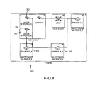
- FIG. 4 illustrates an example of highlighted connection paths for a particular node in a network topology display according to an embodiment of the present invention.
- FIG. 1 illustrates an exemplary display system 10 suitable for implementing a network topology display according to the present invention.
- Display system 10 includes client device 20 , coupled to, or including display device 30 and user interface device 40 .
- Client device 20 could be a desktop personal computer, workstation, laptop computer, or any other computing device including components capable of interfacing directly or indirectly with the desired network(s) 50 for which a topology display is desired.
- Network 50 can be a storage area network (SAN), such as a Fibre-channel-based or SCSI-based SAN, or any other type of network.
- SAN storage area network
- Each client 20 typically runs an application program allowing a user of client 20 to analyze the topology of the network(s) as will be discussed in more detail below.
- Each client device 20 also typically includes one or more user interface devices 40 , such as a keyboard, a mouse, touchscreen, pen or the like, for interacting with a graphical user interface (GUI) provided by the application program on a display device 30 .
- GUI graphical user interface
- display device 30 is any device capable of rendering a topology display of the network(s) 50 including, for example, a monitor screen, LCD display, printer, etc.
- the application program typically includes computer code run using a central processing unit such as an Intel Pentium processor or the like.
- Computer code for operating and configuring client 20 as described herein is preferably stored on a hard disk, but the entire program code, or portions thereof, may also be stored in any other memory device such as a ROM or RAM, or provided on any media capable of storing program code, such as a compact disk (CD) medium, a floppy disk, or the like.
- the entire program code, or portions thereof may be downloaded from a software source to client 20 over the Internet as is well known, or transmitted over any other conventional network connection as is well known, e.g., extranet, VPN, LAN, etc., using any communication medium and protocols (e.g., TCP/IP, HTTP, HTTPS, Ethernet, etc.) as are well known.
- portions of the program code may be downloaded or provided to client device 20 and executed on client device 20 .
- portions of the program code are executed simultaneously at different locations (e.g., one or more clients 20 are connected to one or more servers) and the communication between the different parts is transmitted over the Internet or other network connection/medium.
- FIG. 2 illustrates a portion of a network topology display according to the present invention.
- screen display 100 includes multiple interconnected nodes.
- Nodes include any type of network device or network communication device, such as network hubs, servers, switches, client computers, routers, etc., or any group of interconnected devices.
- loop group node 140 represents one or more network devices interconnected over a network communication loop, e.g., a Fibre-channel FC-AL loop or other loop or network medium.
- Loop Group node 140 is displayed as a single node rather than as the separate individual device nodes making up the group loop node to simplify the display for the viewer.
- each of displayed Switch group nodes 110 , 120 , and 130 represent a network switch device and any devices connected locally thereto.
- Host group node 150 is displayed in an “expanded” mode whereby individual devices in the group are displayed as individual nodes within the host group node box 150 .
- Application Ser. No. 09/539,350 entitled “Methods for Displaying Nodes of a Network Using a Multilayer Representation,” which is hereby incorporated by reference in its entirety for all purposes, provides an example of techniques for identifying network devices, grouping the network devices into appropriate groups and displaying corresponding device and group nodes. The user may selectively expand and contract the group nodes using user input device 40 as desired.
- the term “node” will be used hereafter to refer to both device and group nodes to simplify the description.
- each node is generally connected to one or more other nodes by lines or connection paths, each including one or more segments.
- the connection path 124 connecting switch node 110 to switch node 130 includes one segment
- the connection path between switch node 110 and switch node 120 includes multiple segments.
- Each connection path between nodes in the display is preferably broken into one or more orthogonal segments.
- the connection paths include horizontal and vertical segments as this provides the user with a clean display interface since oblique segments are known to be difficult to display on a computer or monitor screen, e.g., due to aliasing.
- multiple connection paths coupled to a node from the same general direction are overlapped intentionally to simplify the visual representation of the network.
- segment 122 of the connection path between switch nodes 110 and 120 overlaps with a portion of the connection path between loop node 140 and switch node 120 .
- Such overlapping is particularly useful in complex networks including many, many connections.
- distinguishing connector segments are advantageously used to connect orthogonal segments so as to remove some of the ambiguity arising from the nature of orthogonal drawings.
- rounded corner connector 114 connects segment 112 and segment 116
- connector 118 connects segment 116 to segment 122 .
- Such distinguishing connector segments provide a sense of direction to the connection path and are particularly useful in the case where connection segments overlap.
- connector segments e.g., rounded corner segments 114 and 118
- connector 118 might include a single line connecting to both segment 116 and segment 122 at a 45° angle. Such a single line connector would indicate the connection between switch node 110 and switch node 120 .
- connector 118 includes two or more polygonal segments (e.g, each segment connecting to the next at an angle less than 180°) with two segments connecting to segments 116 and 122 at any angle other than 90° so as to distinguish the connectivity of the connection path connecting to switch node 110 .
- FIG. 3 illustrates a portion of a network topology display including a highlighted connection path according to an embodiment of the present invention.
- screen display 200 includes multiple nodes and connection paths similar to FIG. 2 .
- Connection path 216 connecting switch node 210 and switch node 220 is shown in a “highlighted” state responsive to a user selection of the connection between those nodes.
- the user may highlight a desired connection path by “mousing over” the connection path using the user input device 40 .
- connection path is highlighted.
- the connection path is highlighted by emboldening.(e.g., increasing the thickness) the connection path as shown in FIG. 3, however, the selected connection path may be displayed in a different color, may be made to flash (e.g., on and off, alternating colors, etc.) or the selected connection path may be displayed as a dotted line or a thinner line.
- any method that distinguishes the selected connection path may be used. Such highlighting is particularly useful in cases where connection paths overlap partially.
- FIG. 4 illustrates a portion of a network topology display 300 including multiple highlighted connection paths according to an embodiment of the present invention.
- screen display 300 includes multiple nodes and connection paths similar to FIGS. 2 and 3. All connection paths connecting switch node 330 with one or more other nodes i.e., nodes 352 , 354 in host group 350 and nodes in switch group 310 , are shown in a “highlighted” state responsive to a user selection of all the connections for switch node 330 .
- highlighting of the connection paths can include emboldening, thinning, coloration, flashing, etc.
- the user can select all connections of a particular node by clicking on the node, or selecting the node from a list of nodes.
- any form of a command that the user can execute on a node to identify all the links connected to that node can be used.
- Other embodiments include presenting the user with a list of network connections which is synchronized with the topology display in such a way that selecting one connection in the topology display or in the list display causes the same connection in the other display to be selected and/or highlighted.
Abstract
Description
Claims (32)
Priority Applications (1)
| Application Number | Priority Date | Filing Date | Title |
|---|---|---|---|
| US09/823,726 US6833850B1 (en) | 2000-08-28 | 2001-03-30 | Method for simplifying display of complex network connections through partial overlap of connections in displayed segments |
Applications Claiming Priority (2)
| Application Number | Priority Date | Filing Date | Title |
|---|---|---|---|
| US22854700P | 2000-08-28 | 2000-08-28 | |
| US09/823,726 US6833850B1 (en) | 2000-08-28 | 2001-03-30 | Method for simplifying display of complex network connections through partial overlap of connections in displayed segments |
Publications (1)
| Publication Number | Publication Date |
|---|---|
| US6833850B1 true US6833850B1 (en) | 2004-12-21 |
Family
ID=33513585
Family Applications (1)
| Application Number | Title | Priority Date | Filing Date |
|---|---|---|---|
| US09/823,726 Expired - Lifetime US6833850B1 (en) | 2000-08-28 | 2001-03-30 | Method for simplifying display of complex network connections through partial overlap of connections in displayed segments |
Country Status (1)
| Country | Link |
|---|---|
| US (1) | US6833850B1 (en) |
Cited By (22)
| Publication number | Priority date | Publication date | Assignee | Title |
|---|---|---|---|---|
| US20030055932A1 (en) * | 2001-09-19 | 2003-03-20 | Dell Products L.P. | System and method for configuring a storage area network |
| US20030140128A1 (en) * | 2002-01-18 | 2003-07-24 | Dell Products L.P. | System and method for validating a network |
| US20030204580A1 (en) * | 2002-04-25 | 2003-10-30 | Baldwin Duane Mark | Methods and apparatus for management of mixed protocol storage area networks |
| US20050281272A1 (en) * | 2004-06-17 | 2005-12-22 | Chandrapal Sarayu S | Displaying virtual network properties in a graphical user interface |
| US20060168207A1 (en) * | 2005-01-24 | 2006-07-27 | Choong Jason Y C | Network analysis system and method |
| US20070043880A1 (en) * | 2005-08-17 | 2007-02-22 | Reeves Matthew S | Remotely associating network ports to a server |
| US20070113185A1 (en) * | 2005-11-16 | 2007-05-17 | Microsoft Corporation | Intelligent network diagram layout |
| US20070156860A1 (en) * | 2005-12-30 | 2007-07-05 | Microsoft Corporation | Implementing computer application topologies on virtual machines |
| US20070156861A1 (en) * | 2005-12-30 | 2007-07-05 | Microsoft Corporation | Discovering, defining, and implementing computer application topologies |
| US20090147703A1 (en) * | 2005-10-26 | 2009-06-11 | James Wesley Bemont | Method for Efficiently Retrieving Topology-Specific Data for Point-to-Point Networks |
| US20100082781A1 (en) * | 2004-07-01 | 2010-04-01 | Mark Lubeck | Network connectivity |
| US20100153385A1 (en) * | 2007-09-07 | 2010-06-17 | Foundry Networks, Inc. | Search in network management UI controls |
| US20110131324A1 (en) * | 2007-05-24 | 2011-06-02 | Animesh Chaturvedi | Managing network security |
| US20110131398A1 (en) * | 2007-05-24 | 2011-06-02 | Animesh Chaturvedi | Generating device-specific configurations |
| US8032540B1 (en) | 2004-10-29 | 2011-10-04 | Foundry Networks, Inc. | Description-based user interface engine for network management applications |
| US8352620B2 (en) | 2010-07-27 | 2013-01-08 | Hewlett-Packard Development Company, L.P. | Displaying a network topology map with a reduced number of objects |
| US20130103720A1 (en) * | 2011-10-24 | 2013-04-25 | Lexisnexis, A Division Of Reed Elsevier Inc. | Systems and Methods For Providing For Display A Map That Graphically Represents The Association Among Documents |
| US20130290878A1 (en) * | 2012-04-13 | 2013-10-31 | Huawei Technologies Co., Ltd. | Generation and display method of user interface and user interface device |
| US9160630B2 (en) * | 2011-06-07 | 2015-10-13 | Vmware, Inc. | Network connectivity and security visualization |
| US10652280B2 (en) * | 2017-04-24 | 2020-05-12 | Unisys Corporation | User interface features for enterprise security management |
| US10863330B1 (en) * | 2015-12-03 | 2020-12-08 | Eta Vision Inc. | Systems and methods for sensing, recording, analyzing and reporting environmental conditions in data centers and similar facilities |
| US11284544B1 (en) * | 2015-12-03 | 2022-03-22 | Eta Vision Inc. | Systems and methods for sensing, recording, analyzing and reporting environmental conditions in data centers and similar facilities |
Citations (16)
| Publication number | Priority date | Publication date | Assignee | Title |
|---|---|---|---|---|
| US5276789A (en) | 1990-05-14 | 1994-01-04 | Hewlett-Packard Co. | Graphic display of network topology |
| US5278951A (en) | 1991-04-22 | 1994-01-11 | France Telecom Etablissement Autonome De Droit Public | Decompilation process for producing graphs by means of a computer |
| US5408603A (en) * | 1992-03-31 | 1995-04-18 | Dow Benelux N.V. | Global process control information system and method |
| US5751965A (en) * | 1996-03-21 | 1998-05-12 | Cabletron System, Inc. | Network connection status monitor and display |
| US5910803A (en) | 1996-08-14 | 1999-06-08 | Novell, Inc. | Network atlas mapping tool |
| US6014715A (en) | 1994-11-08 | 2000-01-11 | Mcdata Corporation | Method and apparatus for assigning port addresses |
| US6067093A (en) | 1996-08-14 | 2000-05-23 | Novell, Inc. | Method and apparatus for organizing objects of a network map |
| US6072490A (en) * | 1997-08-15 | 2000-06-06 | International Business Machines Corporation | Multi-node user interface component and method thereof for use in accessing a plurality of linked records |
| US6078324A (en) | 1997-01-21 | 2000-06-20 | Netiq Corporation | Event signaling in a foldable object tree |
| US6078739A (en) * | 1997-11-25 | 2000-06-20 | Entelos, Inc. | Method of managing objects and parameter values associated with the objects within a simulation model |
| US6154212A (en) * | 1997-11-06 | 2000-11-28 | Lucent Technologies Inc. | Method and apparatus for constructing network interfaces |
| US6229538B1 (en) * | 1998-09-11 | 2001-05-08 | Compaq Computer Corporation | Port-centric graphic representations of network controllers |
| US6295575B1 (en) * | 1998-06-29 | 2001-09-25 | Emc Corporation | Configuring vectors of logical storage units for data storage partitioning and sharing |
| US6331983B1 (en) * | 1997-05-06 | 2001-12-18 | Enterasys Networks, Inc. | Multicast switching |
| US6369819B1 (en) | 1998-04-17 | 2002-04-09 | Xerox Corporation | Methods for visualizing transformations among related series of graphs |
| US6374293B1 (en) * | 1990-09-17 | 2002-04-16 | Aprisma Management Technologies, Inc. | Network management system using model-based intelligence |
-
2001
- 2001-03-30 US US09/823,726 patent/US6833850B1/en not_active Expired - Lifetime
Patent Citations (16)
| Publication number | Priority date | Publication date | Assignee | Title |
|---|---|---|---|---|
| US5276789A (en) | 1990-05-14 | 1994-01-04 | Hewlett-Packard Co. | Graphic display of network topology |
| US6374293B1 (en) * | 1990-09-17 | 2002-04-16 | Aprisma Management Technologies, Inc. | Network management system using model-based intelligence |
| US5278951A (en) | 1991-04-22 | 1994-01-11 | France Telecom Etablissement Autonome De Droit Public | Decompilation process for producing graphs by means of a computer |
| US5408603A (en) * | 1992-03-31 | 1995-04-18 | Dow Benelux N.V. | Global process control information system and method |
| US6014715A (en) | 1994-11-08 | 2000-01-11 | Mcdata Corporation | Method and apparatus for assigning port addresses |
| US5751965A (en) * | 1996-03-21 | 1998-05-12 | Cabletron System, Inc. | Network connection status monitor and display |
| US5910803A (en) | 1996-08-14 | 1999-06-08 | Novell, Inc. | Network atlas mapping tool |
| US6067093A (en) | 1996-08-14 | 2000-05-23 | Novell, Inc. | Method and apparatus for organizing objects of a network map |
| US6078324A (en) | 1997-01-21 | 2000-06-20 | Netiq Corporation | Event signaling in a foldable object tree |
| US6331983B1 (en) * | 1997-05-06 | 2001-12-18 | Enterasys Networks, Inc. | Multicast switching |
| US6072490A (en) * | 1997-08-15 | 2000-06-06 | International Business Machines Corporation | Multi-node user interface component and method thereof for use in accessing a plurality of linked records |
| US6154212A (en) * | 1997-11-06 | 2000-11-28 | Lucent Technologies Inc. | Method and apparatus for constructing network interfaces |
| US6078739A (en) * | 1997-11-25 | 2000-06-20 | Entelos, Inc. | Method of managing objects and parameter values associated with the objects within a simulation model |
| US6369819B1 (en) | 1998-04-17 | 2002-04-09 | Xerox Corporation | Methods for visualizing transformations among related series of graphs |
| US6295575B1 (en) * | 1998-06-29 | 2001-09-25 | Emc Corporation | Configuring vectors of logical storage units for data storage partitioning and sharing |
| US6229538B1 (en) * | 1998-09-11 | 2001-05-08 | Compaq Computer Corporation | Port-centric graphic representations of network controllers |
Cited By (47)
| Publication number | Priority date | Publication date | Assignee | Title |
|---|---|---|---|---|
| US20030055932A1 (en) * | 2001-09-19 | 2003-03-20 | Dell Products L.P. | System and method for configuring a storage area network |
| US7603446B2 (en) | 2001-09-19 | 2009-10-13 | Dell Products L.P. | System and method for configuring a storage area network |
| US20080065748A1 (en) * | 2001-09-19 | 2008-03-13 | Dell Products L.P. | System and Method for Configuring a Storage Area Network |
| US20030140128A1 (en) * | 2002-01-18 | 2003-07-24 | Dell Products L.P. | System and method for validating a network |
| US20080183856A1 (en) * | 2002-04-25 | 2008-07-31 | Duane Mark Baldwin | Methods and apparatus for management of mixed protocol storage area networks |
| US20030204580A1 (en) * | 2002-04-25 | 2003-10-30 | Baldwin Duane Mark | Methods and apparatus for management of mixed protocol storage area networks |
| US7827317B2 (en) | 2002-04-25 | 2010-11-02 | International Business Machines Corporation | Apparatus for management of mixed protocol storage networks |
| US7398326B2 (en) * | 2002-04-25 | 2008-07-08 | International Business Machines Corporation | Methods for management of mixed protocol storage area networks |
| US20050281272A1 (en) * | 2004-06-17 | 2005-12-22 | Chandrapal Sarayu S | Displaying virtual network properties in a graphical user interface |
| US20100082781A1 (en) * | 2004-07-01 | 2010-04-01 | Mark Lubeck | Network connectivity |
| US8175001B2 (en) | 2004-07-01 | 2012-05-08 | Brocade Communications Systems, Inc. | Network connectivity |
| US8032540B1 (en) | 2004-10-29 | 2011-10-04 | Foundry Networks, Inc. | Description-based user interface engine for network management applications |
| US7792956B2 (en) * | 2005-01-24 | 2010-09-07 | Daintree Networks, Pty. Ltd. | Network analysis system and method |
| US8370483B2 (en) | 2005-01-24 | 2013-02-05 | Daintree Networks, Pty. Ltd. | Network analysis system and method |
| US20100135186A1 (en) * | 2005-01-24 | 2010-06-03 | Daintree Networks, Pty. Ltd. | Network Analysis System and Method |
| US20060168207A1 (en) * | 2005-01-24 | 2006-07-27 | Choong Jason Y C | Network analysis system and method |
| US8650268B2 (en) | 2005-08-17 | 2014-02-11 | Hewlett-Packard Development Company, L.P. | Remotely associating network ports to a server |
| US20070043880A1 (en) * | 2005-08-17 | 2007-02-22 | Reeves Matthew S | Remotely associating network ports to a server |
| US20140328212A1 (en) * | 2005-10-26 | 2014-11-06 | Memory Integrity, Llc | Method for Efficiently Retrieving Topology-Specific Data for Point-to-Point Networks |
| US20130182612A1 (en) * | 2005-10-26 | 2013-07-18 | Sanmina Corporation | Method for Efficiently Retrieving Topology-Specific Data for Point-to-Point Networks |
| US20090147703A1 (en) * | 2005-10-26 | 2009-06-11 | James Wesley Bemont | Method for Efficiently Retrieving Topology-Specific Data for Point-to-Point Networks |
| US8811232B2 (en) * | 2005-10-26 | 2014-08-19 | Memory Integrity, Llc | Method for efficiently retrieving topology-specific data for point-to-point networks |
| US8411591B2 (en) * | 2005-10-26 | 2013-04-02 | Sanmina Corporation | Method for efficiently retrieving topology-specific data for point-to-point networks |
| US20070113185A1 (en) * | 2005-11-16 | 2007-05-17 | Microsoft Corporation | Intelligent network diagram layout |
| US20100218103A1 (en) * | 2005-12-30 | 2010-08-26 | Microsoft Corporation | Discovering, defining, and implementing computer application topologies |
| US7774446B2 (en) | 2005-12-30 | 2010-08-10 | Microsoft Corporation | Discovering, defining, and implementing computer application topologies |
| US10341187B2 (en) | 2005-12-30 | 2019-07-02 | Microsoft Technology Licensing, Llc | Discovering, defining, and implementing computer application topologies |
| US8145737B2 (en) | 2005-12-30 | 2012-03-27 | Microsoft Corporation | Implementing computer application topologies on virtual machines |
| US20070156861A1 (en) * | 2005-12-30 | 2007-07-05 | Microsoft Corporation | Discovering, defining, and implementing computer application topologies |
| US8312127B2 (en) | 2005-12-30 | 2012-11-13 | Microsoft Corporation | Discovering, defining, and implementing computer application topologies |
| US20070156860A1 (en) * | 2005-12-30 | 2007-07-05 | Microsoft Corporation | Implementing computer application topologies on virtual machines |
| US20110131398A1 (en) * | 2007-05-24 | 2011-06-02 | Animesh Chaturvedi | Generating device-specific configurations |
| US20110131324A1 (en) * | 2007-05-24 | 2011-06-02 | Animesh Chaturvedi | Managing network security |
| US8341739B2 (en) | 2007-05-24 | 2012-12-25 | Foundry Networks, Llc | Managing network security |
| US8782182B2 (en) | 2007-05-24 | 2014-07-15 | Foundry Networks, Llc | Generating device-specific configurations |
| US8650295B2 (en) | 2007-05-24 | 2014-02-11 | Foundry Networks, Llc | Managing network security |
| US9141688B2 (en) | 2007-09-07 | 2015-09-22 | Foundry Networks Llc | Search in network management UI controls |
| US20100153385A1 (en) * | 2007-09-07 | 2010-06-17 | Foundry Networks, Inc. | Search in network management UI controls |
| US8352620B2 (en) | 2010-07-27 | 2013-01-08 | Hewlett-Packard Development Company, L.P. | Displaying a network topology map with a reduced number of objects |
| US9160630B2 (en) * | 2011-06-07 | 2015-10-13 | Vmware, Inc. | Network connectivity and security visualization |
| US20130103720A1 (en) * | 2011-10-24 | 2013-04-25 | Lexisnexis, A Division Of Reed Elsevier Inc. | Systems and Methods For Providing For Display A Map That Graphically Represents The Association Among Documents |
| US9946700B2 (en) * | 2011-10-24 | 2018-04-17 | Lexisnexis, A Division Of Reed Elsevier Inc. | Systems and methods for providing for display a map that graphically represents the association among documents |
| US20130290878A1 (en) * | 2012-04-13 | 2013-10-31 | Huawei Technologies Co., Ltd. | Generation and display method of user interface and user interface device |
| US10863330B1 (en) * | 2015-12-03 | 2020-12-08 | Eta Vision Inc. | Systems and methods for sensing, recording, analyzing and reporting environmental conditions in data centers and similar facilities |
| US11284544B1 (en) * | 2015-12-03 | 2022-03-22 | Eta Vision Inc. | Systems and methods for sensing, recording, analyzing and reporting environmental conditions in data centers and similar facilities |
| US11405760B1 (en) * | 2015-12-03 | 2022-08-02 | EtaVision Inc. | Systems and methods for sensing, recording, analyzing and reporting environmental conditions in data centers and similar facilities |
| US10652280B2 (en) * | 2017-04-24 | 2020-05-12 | Unisys Corporation | User interface features for enterprise security management |
Similar Documents
| Publication | Publication Date | Title |
|---|---|---|
| US6833850B1 (en) | Method for simplifying display of complex network connections through partial overlap of connections in displayed segments | |
| US7310774B1 (en) | Method for displaying switch port information in a network topology display | |
| US9189144B2 (en) | Multi-touch gesture-based interface for network design and management | |
| US10255401B2 (en) | Viewing multi paired schematic and layout windows on printed circuit board (PCB) design software and tools | |
| US7415671B2 (en) | Interactive hierarchical status display | |
| US7603446B2 (en) | System and method for configuring a storage area network | |
| US5768552A (en) | Graphical representation of computer network topology and activity | |
| US11900673B2 (en) | Identifying cable ends using augmented reality | |
| KR101666417B1 (en) | Computer system security dashboard | |
| US8407347B2 (en) | Method of operating multiple input and output devices through a single computer | |
| EP3570493A1 (en) | Systems and methods for context based multi-dimensional network visualization | |
| US6836275B1 (en) | Method for distinguishing between single and multiple connections in a network topology | |
| KR101863425B1 (en) | Multiple displays for displaying workspaces | |
| US6646656B1 (en) | Graphical representation of the connections between network devices and their configuration | |
| JPH0727504B2 (en) | System for defining network configuration, method for generating configuration parameters for network, and system for configuring network | |
| US20180139111A1 (en) | Enterprise application integration on client computing devices | |
| KR20150043344A (en) | Integrating co-browsing with other forms of information sharing | |
| CN107479957A (en) | A kind of switching method of Multiple system, device, equipment and storage medium | |
| JP2004152282A (en) | Storage area network management device | |
| WO2014036830A1 (en) | Resource information display method and apparatus | |
| US9164851B2 (en) | Keyboard, video and mouse switch identifying and displaying nodes experiencing a problem | |
| US8836802B2 (en) | Method of defining camera scan movements using gestures | |
| US20080010606A1 (en) | Graphical user interface device and method for security application rack | |
| US20130265328A1 (en) | Methods and systems for providing video overlay for display coupled to integrated chassis housing a plurality of modular information handling systems | |
| US20110307793A1 (en) | System and method for visualizing an address space |
Legal Events
| Date | Code | Title | Description |
|---|---|---|---|
| AS | Assignment |
Owner name: SANAVIGATOR, INC., CALIFORNIA Free format text: ASSIGNMENT OF ASSIGNORS INTEREST;ASSIGNORS:ARQUIE, LOUIS;CORNETT, LARRY L.;REEL/FRAME:012032/0653 Effective date: 20010725 |
|
| AS | Assignment |
Owner name: SANNAV NEWCO, INC., COLORADO Free format text: ASSIGNMENT OF ASSIGNORS INTEREST;ASSIGNOR:SANAVIGATOR, INC.;REEL/FRAME:012334/0033 Effective date: 20010921 |
|
| AS | Assignment |
Owner name: SANAVIGATOR, INC., COLORADO Free format text: CHANGE OF NAME;ASSIGNOR:SANNAV NEWCO, INC.;REEL/FRAME:012387/0809 Effective date: 20010926 |
|
| AS | Assignment |
Owner name: SANAVIGATOR, INC., COLORADO Free format text: CHANGE OF NAME;ASSIGNOR:SANNAV NEWCO, INC.;REEL/FRAME:012432/0078 Effective date: 20010926 |
|
| AS | Assignment |
Owner name: SANAVIGATOR, INC., COLORADO Free format text: CHANGE OF NAME;ASSIGNOR:SANNAV NEWCO, INC.;REEL/FRAME:012623/0881 Effective date: 20010926 Owner name: SANAVIGATOR, INC., COLORADO Free format text: CHANGE OF NAME;ASSIGNOR:SANNAV NEWCO, INC.;REEL/FRAME:012700/0542 Effective date: 20010926 |
|
| AS | Assignment |
Owner name: SANNAV NEWCO, INC., COLORADO Free format text: ASSIGNMENT OF ASSIGNORS INTEREST;ASSIGNOR:SANAVIGATOR, INC.;REEL/FRAME:012387/0734 Effective date: 20010921 |
|
| STCF | Information on status: patent grant |
Free format text: PATENTED CASE |
|
| AS | Assignment |
Owner name: BROCADE COMMUNICATIONS SYSTEMS, INC., CALIFORNIA Free format text: ASSIGNMENT OF ASSIGNORS INTEREST;ASSIGNOR:SANAVIGATOR, INC.;REEL/FRAME:020271/0870 Effective date: 20071206 |
|
| FPAY | Fee payment |
Year of fee payment: 4 |
|
| FEPP | Fee payment procedure |
Free format text: PAYOR NUMBER ASSIGNED (ORIGINAL EVENT CODE: ASPN); ENTITY STATUS OF PATENT OWNER: LARGE ENTITY |
|
| AS | Assignment |
Owner name: BANK OF AMERICA, N.A. AS ADMINISTRATIVE AGENT, CAL Free format text: SECURITY AGREEMENT;ASSIGNORS:BROCADE COMMUNICATIONS SYSTEMS, INC.;FOUNDRY NETWORKS, INC.;INRANGE TECHNOLOGIES CORPORATION;AND OTHERS;REEL/FRAME:022012/0204 Effective date: 20081218 Owner name: BANK OF AMERICA, N.A. AS ADMINISTRATIVE AGENT,CALI Free format text: SECURITY AGREEMENT;ASSIGNORS:BROCADE COMMUNICATIONS SYSTEMS, INC.;FOUNDRY NETWORKS, INC.;INRANGE TECHNOLOGIES CORPORATION;AND OTHERS;REEL/FRAME:022012/0204 Effective date: 20081218 |
|
| AS | Assignment |
Owner name: WELLS FARGO BANK, NATIONAL ASSOCIATION, AS COLLATE Free format text: SECURITY AGREEMENT;ASSIGNORS:BROCADE COMMUNICATIONS SYSTEMS, INC.;FOUNDRY NETWORKS, LLC;INRANGE TECHNOLOGIES CORPORATION;AND OTHERS;REEL/FRAME:023814/0587 Effective date: 20100120 |
|
| FPAY | Fee payment |
Year of fee payment: 8 |
|
| AS | Assignment |
Owner name: BROCADE COMMUNICATIONS SYSTEMS, INC., CALIFORNIA Free format text: RELEASE BY SECURED PARTY;ASSIGNOR:BANK OF AMERICA, N.A., AS ADMINISTRATIVE AGENT;REEL/FRAME:034792/0540 Effective date: 20140114 Owner name: INRANGE TECHNOLOGIES CORPORATION, CALIFORNIA Free format text: RELEASE BY SECURED PARTY;ASSIGNOR:BANK OF AMERICA, N.A., AS ADMINISTRATIVE AGENT;REEL/FRAME:034792/0540 Effective date: 20140114 Owner name: FOUNDRY NETWORKS, LLC, CALIFORNIA Free format text: RELEASE BY SECURED PARTY;ASSIGNOR:BANK OF AMERICA, N.A., AS ADMINISTRATIVE AGENT;REEL/FRAME:034792/0540 Effective date: 20140114 |
|
| AS | Assignment |
Owner name: FOUNDRY NETWORKS, LLC, CALIFORNIA Free format text: RELEASE BY SECURED PARTY;ASSIGNOR:WELLS FARGO BANK, NATIONAL ASSOCIATION, AS COLLATERAL AGENT;REEL/FRAME:034804/0793 Effective date: 20150114 Owner name: BROCADE COMMUNICATIONS SYSTEMS, INC., CALIFORNIA Free format text: RELEASE BY SECURED PARTY;ASSIGNOR:WELLS FARGO BANK, NATIONAL ASSOCIATION, AS COLLATERAL AGENT;REEL/FRAME:034804/0793 Effective date: 20150114 |
|
| REMI | Maintenance fee reminder mailed | ||
| FPAY | Fee payment |
Year of fee payment: 12 |
|
| SULP | Surcharge for late payment |
Year of fee payment: 11 |
|
| AS | Assignment |
Owner name: BROCADE COMMUNICATIONS SYSTEMS LLC, CALIFORNIA Free format text: CHANGE OF NAME;ASSIGNOR:BROCADE COMMUNICATIONS SYSTEMS, INC.;REEL/FRAME:044891/0536 Effective date: 20171128 |
|
| AS | Assignment |
Owner name: AVAGO TECHNOLOGIES INTERNATIONAL SALES PTE. LIMITED, SINGAPORE Free format text: ASSIGNMENT OF ASSIGNORS INTEREST;ASSIGNOR:BROCADE COMMUNICATIONS SYSTEMS LLC;REEL/FRAME:047270/0247 Effective date: 20180905 Owner name: AVAGO TECHNOLOGIES INTERNATIONAL SALES PTE. LIMITE Free format text: ASSIGNMENT OF ASSIGNORS INTEREST;ASSIGNOR:BROCADE COMMUNICATIONS SYSTEMS LLC;REEL/FRAME:047270/0247 Effective date: 20180905 |