US6826160B1 - Dynamic bandwidth allocation through multi-channel time slot assignment and migration for broadband access - Google Patents
Dynamic bandwidth allocation through multi-channel time slot assignment and migration for broadband access Download PDFInfo
- Publication number
- US6826160B1 US6826160B1 US09/348,983 US34898399A US6826160B1 US 6826160 B1 US6826160 B1 US 6826160B1 US 34898399 A US34898399 A US 34898399A US 6826160 B1 US6826160 B1 US 6826160B1
- Authority
- US
- United States
- Prior art keywords
- channels
- network
- transmitting channels
- specific transmitting
- loading condition
- Prior art date
- Legal status (The legal status is an assumption and is not a legal conclusion. Google has not performed a legal analysis and makes no representation as to the accuracy of the status listed.)
- Expired - Lifetime
Links
Images


Classifications
-
- H—ELECTRICITY
- H04—ELECTRIC COMMUNICATION TECHNIQUE
- H04W—WIRELESS COMMUNICATION NETWORKS
- H04W28/00—Network traffic management; Network resource management
- H04W28/16—Central resource management; Negotiation of resources or communication parameters, e.g. negotiating bandwidth or QoS [Quality of Service]
- H04W28/18—Negotiating wireless communication parameters
- H04W28/20—Negotiating bandwidth
-
- H—ELECTRICITY
- H04—ELECTRIC COMMUNICATION TECHNIQUE
- H04L—TRANSMISSION OF DIGITAL INFORMATION, e.g. TELEGRAPHIC COMMUNICATION
- H04L47/00—Traffic control in data switching networks
- H04L47/70—Admission control; Resource allocation
- H04L47/76—Admission control; Resource allocation using dynamic resource allocation, e.g. in-call renegotiation requested by the user or requested by the network in response to changing network conditions
Definitions
- the present claimed invention relates to the field of network communication. Specifically, the present claimed invention relates to an apparatus and a method for dynamically allocating time slots in multiple channels of a bandwidth over which a device may communicate in a network.
- BAN Broadband Access Network
- FIG. 1 a presents a block diagram of a conventional shared media network system.
- four devices e.g. Customer Premises Equipment (CPE), 104 a , 104 b , 104 c , and 104 d are coupled to a hub 102 via link 106 .
- Link 106 can provide multiple channels of communication, typically dependent upon the transmitter/receiver capabilities of devices 104 a , 104 b , 104 c , and 104 d and the hub 102 .
- contention access There are two basic methods of communicating in the present network, contention access, and reservation access.
- reservation access a device sends a request to a hub to reserve a specific length of transmission on the network.
- the hub processes the request, reserves a slot on the network for the requesting device, and sends instructions to the device telling it when to transmit. Subsequently, the device transmits its information according to the instructions. This process avoids collisions, but it also consumes time and resources to make and process the request.
- Delay sensitive applications such as Internet Telephony and video conferencing require the quality of service delivered by reservation access protocol.
- contention access any device in a network can communicate when it has information ready to transmit and when a unused time slot appears. Unfortunately, if more than one device meets the same criteria and tries to transmit at the same time, a collision may arise. If a collision arises, the hub will send a message to the relevant devices indicating that the transmission has failed. Consequently, any device involved in a collision will have to attempt to retransmit the information.
- the multiple access protocol is generally a combination of reservation access and contention access for Internet access and Telephony services. A separate downlink channel is available for the hub to communicate to the devices. However, there are much fewer problems with the downlink channel than the uplink channel because a single entity, the hub, controls all transmissions on the downlink.
- FIG. 1 b provides an illustration of multiple uplink channels (channels) that can be used in a hub-spoke network. It also exemplifies a conventional assignment of time slots in multiple channels over which multiple devices will communicate.
- the illustration presents a contention access scenario where devices communicate and hope to avoid a collision.
- three channels, channel AA 154 , channel BB 152 , and channel CC 153 are shown in parallel as they span the spectrum 164 of the network. They represent different frequency channels within the bandwidth, or spectrum 164 , of the network. As shown, several packets fill up lower channel AA 154 .
- This scenario illustrates that the efficiency of contention access drops when a large number of time slots in a shared channel are assigned to network devices by the reservation protocol.
- a first attempt to transmit a data packet 162 a for device D 104 d and a second attempt to transmit a data packet 162 b for device D 104 d , occur because device D 104 d cannot locate an available time slot in which to transmit.
- device D 104 d has an extended wait time for communicating, and a lower quality of service. Consequently, a need arises for a method of allowing a fairer and more consistent access to the network by devices.
- One of the conventional methods of providing access to the network when one channel becomes very busy is to force the device, whose transmission is being blocked, to migrate to an empty uplink channel.
- device D 104 d can migrate up to channel BB 152 after repeatedly being blocked in its originally allocated channel, channel AA 154 .
- this process is inefficient.
- Channel resources may be overburdened in one channel and underutilized in another channel.
- the waiting period for the blocked device and the consequent migration process consumes valuable time and results in substandard communication performance. Consequently, a need arises for a method to more evenly utilize the multiple channel resources and thereby provide better communication performance to the user.
- a user will typically transmit in just that given channel for consecutive data packets. Even if a user is forced to migrate to another channel, the user will transmit just in the new channel to which it migrated. However, sometimes two or more channels are equally busy or loaded, and assigning a device to transmit entirely on one or the other channel will cause congestion. Hence, a need arises for a method and apparatus to allow a new device to transmit on evenly loaded channels without upsetting the even loading.
- a device is conventionally allocated a default channel on which to transmit.
- This default channel conventionally remains the same for a given device.
- different devices may be assigned to different channels in the multichannel BAN, they still maintain their default channel each time they access the network.
- the bandwidth utilization can vary at any given time depending on the number of devices that are active or idle on that channel. Consequently, different channels in a multichannel network can have vastly different loading depending on whether, or when, devices log on to their allocated channel.
- the loading in each channel can be highly non-uniform if a device with a low bandwidth capability is grouped into a channel having a large bandwidth. The varied loading might mean overcrowding on one channel and unused resources on another channel.
- device A 104 a , device B 104 b , device C 104 c , and device D 104 d are all allocated to the same default channel, channel AA 154 .
- these devices could have been assigned to a different default channel. The point is that, regardless of which channel they are on, once a device is assigned to a channel, the assignment does not change. As a result of this rigid convention, a need arises for a method to periodically allocate default channels in a dynamic manner to better utilize the resources on a multichannel network.
- Another feature of the conventional protocol is to assign a device just a single fixed channel in which to transmit information.
- more than one service class can be supported on a single network.
- the conventional method does not accomplish this service efficiently.
- the conventional method will create channel bandwidths that are specific to a service class of user.
- Prior Art FIG. 1 c provides an illustration of multiple uplink channels (channels) 170 for different service classes that can be used in a hub-spoke network. Similar to Prior art FIG. 1 b , this new figure also exemplifies a conventional assignment of time slots in multiple channels over which devices in different service classes will communicate. While some of the same devices from Prior Art FIG. 1 b are utilized here, their capabilities and requirements are different from those in Prior Art FIG. 1 b.
- Channel DD has a bandwidth, dedicated to the wide bandwidth user, that is equivalent to the combination of the bandwidth from two channels of FIG. 1 b . If other users in the same network require only a small bandwidth, then another channel is dedicated to their bandwidth requirement, e.g. channel EE 172 .
- These bandwidth assignments are typically fixed and do not change. Consequently, depending upon the quantity of users actively using each service class, a channel could have wasted bandwidth because the bandwidth is reserved for a given class, but is not accessible to another class.
- a large portion of the bandwidth is not utilized for a portion of time, e.g. time slot range 178 .
- a device with a narrower bandwidth might be allowed to use a channel that has a higher bandwidth, this method is still inefficient because it does not utilize the full bandwidth capability of the channel.
- a wide bandwidth device cannot use a narrow bandwidth channel.
- wide bandwidth device A in FIG. 1 c , would not be allowed to transmit on channel EE 172 even though it might need to and even though no traffic might exist on channel EE 172 .
- the prior art was primarily limited to incrementing service based on time slots, since the channel assignments were fixed. Consequently, a need arises for a more flexible manner in which to accommodate multiple service classes on a given bandwidth while balancing channel utilization at the same time.
- Another limitation of the conventional networking is the difficulty involved with changing the service class for a user. If a user has subscribed to a given service class, then a dedicated device is typically used for that specific service class. If the user wishes to change service classes, then a new device for the new service class must be obtained. This method requires time, money, and other resources to accomplish a change in service class. Furthermore, frequency channelization of the bandwidth of the network might have to be rearranged in response to a need for a new service class with a wider bandwidth. Changing the frequency channelization of a network using conventional means could be expensive and time-consuming. In view of these limitations, a need arises for a method to dynamically change the service class for a user without requiring a new device. Another need arises for a method to create a new service class without having to rearrange the frequency channelization of the network bandwidth.
- a conventional device e.g. 104 a , 104 b , 104 c , and 104 d is sometimes required to be a smart unit in order to accomplish some of the contention protocols and methods. That is, it is an expensive device that require a microprocessor capable of performing complicated tasks. To make the device more attractive to users, a need arises for a method to improve network performance and offer flexible service options while only requiring inexpensive dumb devices.
- a need arises for a method of allowing a fairer and more consistent access to the network by devices. Additionally, a need arises for a method to more evenly utilize the multiple channel resources and thereby provide better communication performance to the user. Yet another need arises for a method and apparatus to allow a new device to transmit on evenly loaded channels without upsetting the even loading. Another need arises for a method to periodically allocate default channels in a dynamic manner to better utilize the resources on a multichannel network. Yet another need arises for a more flexible manner in which to accommodate multiple service classes on a given bandwidth while equating channel utilization at the same time. Another need arises for a method to dynamically change the service class for a user without requiring a new device.
- the present invention provides a unique and novel solution that meets all the above needs.
- the present invention provides a method and apparatus for dynamically allocating time slots in multiple channels of a bandwidth over which a device might communicate on the network.
- the present invention recites a method comprising several steps. First, a request to log onto a network is received from a new device.
- the network is a broadband access network (BAN).
- BAN broadband access network
- a loading condition of the network is determined. The loading is determined by the quantity and identity of channels to which each existing device on a network is allocated. A quantity of channels required by new device is then determined according to the service class to which new device subscribed and to the capability of the device. An identity of a quantity of channels on which the new device is allocated to transmit information is determined.
- the identity of the channels is determined according to a desired criteria for the loading condition, such as uniform loading, uniform time-slot vacancies in the multiple channels, uniform quantity of service classes in each channel, or uniform time slot assignments in the multiple channels.
- a time slot allocation for the new device is identified and communicated, along with the identity of the frequency of channels to the device. Then, communication from the new device is received on the allocated time slots on the allocated identity of quantity of channels.
- the time slot allocation is updated periodically with the update of channel loading. In this manner, the present invention allows a fairer and more consistent access to the network by devices because it can dynamically assign a channel to a device depending on the loading condition of the network. Consequently, the present invention more evenly utilizes the multiple channel resources and thereby provides better communication performance to the user.
- the present invention only requires an inexpensive dumb device.
- the prior art would allocate a device to a single channel that would change when the device encountered repeated transmission failures
- the present invention evaluates and decides which of the multiple channels the device should transmit on every time it needs to communicate on the network. Consequently it provides even loading, uniform vacancies, and equitable access for all devices.
- the present invention recites a method for dynamically changing, or managing, the service classes on a network, comprising several steps.
- a request to change a service class is received from a device.
- a user wants to change from a narrow bandwidth service class to a wide bandwidth service class because the user has an newly arisen need for transmitting more data. In that situation, a higher quantity of channels is allocated for the higher service class, thus providing a wider bandwidth.
- the request is verified against the transmission capability of the device and against the subscription service of the device.
- an updated loading condition is determined.
- an identify of the channels over which the device can transmit in the new service class is determined based on the loading condition. Finally, the identify of the channels is determined and communicated to the device.
- the present invention provides a method to dynamically change the service class for a user without requiring a new device.
- the present embodiment also illustrates how the present invention accommodates multiple service classes on a given network bandwidth in flexible manner, while equating channel utilization at the same time.
- the present invention accomplishes the methods on a hub, and thus only requires an inexpensive dumb device.
- FIG. 1 a is a block diagram of a conventional shared media network system.
- FIG. 1 b provides an illustration of multiple channels used in a network and exemplifies a conventional assignment of time slots within the multiple channels to multiple devices.
- FIG. 1 c provides an illustration of conventional multiple service classes over multiple channels used in a network.
- FIG. 2 a is a block diagram of a shared media network system incorporating dynamic bandwidth allocation, in accordance with one embodiment of the present invention.
- FIG. 2 b provides an illustration of multiple channels used in a network and exemplifies the improved assignment of time slots within the multiple channels to multiple devices, in accordance with one embodiment of the present invention.
- FIG. 2 c provides an illustration of multiple channels used in a network and exemplifies the alternating assignment of specific channels to a device, in accordance with one embodiment of the present invention.
- FIG. 3 is a flow chart of the steps performed to dynamically allocate bandwidth in a network, in accordance with one embodiment of the present invention.
- FIG. 4 is a flow chart of the steps performed to provide a plurality of service classes on a network, in accordance with one embodiment of the present invention.
- FIG. 5 is a flow chart of the steps performed to dynamically change the service class of a device in a network, in accordance with one embodiment of the present invention.
- FIG. 6 is a flow chart of the steps performed to allocate sequential alternative transmitting channels in a network, in accordance with one embodiment of the present invention.
- FIG. 2 a presents a block diagram of a shared media network system incorporating dynamic bandwidth allocation, in accordance with one embodiment of the present invention.
- CPEs Customer Premises Equipment
- 204 a , 204 b , 204 c , and 204 d are coupled to a hub 202 via link 206 .
- Link 206 can provide multiple channels of communication, typically dependent upon the transmitter/receiver capabilities of devices 204 a , 204 b , 204 c , and 204 d and the hub 202 .
- the present embodiment utilizes memory in the hub 202 to execute methods found in the following detailed description.
- the present embodiment does not require devices 204 a , 204 b , 204 c , and 204 d to be smart devices. Consequently, the present invention provides a lower cost and less complicated device to the user.
- the hub of FIG. 2 a is comprised of a memory 250 coupled to a processor 252 and to an interface controller 254 .
- memory 250 , processor 252 , and interface controller 254 can be discrete components coupled together in hub 202 .
- another embodiment can provide memory 250 , processor 252 , and interface controller 254 in an integrated circuit.
- Program instructions are stored in memory 250 that contains program instructions for implementing the methods of the present invention.
- program instructions for any of the methods of the present invention can be implemented in hub 202 by using a state-machine device. The methods will be described in more detail hereinafter.
- FIG. 2 b provides an illustration of multiple channels used in a network and exemplifies the improved assignment of time slots within the multiple channels to multiple devices, in accordance with one embodiment of the present invention.
- the illustration presents a contention access scenario where devices communicate and hope to avoid a collision.
- channel FF 256 channel FF 256
- channel GG 254 channel GG 254
- channel HH 252 channel HH 252
- data packets 258 a and 258 b for device A 104 a are transmitted at the same time in multiple channels, channel HH 252 and channel GG 254 , respectively.
- data packets 260 a and 260 b for device B 104 b are transmitted at the same time in multiple channels, channel GG 254 and channel HH 256 respectively.
- channels used for data packets 260 a and 260 b for device B 104 b are shifted up from those channels used for data packets 258 a and 258 b for device A 104 a .
- Alternative embodiments can transmit bandwidths wider than that of a single channel by using any combination of channels. The combination of channels provides the incremental expansion of the bandwidth required for different service classes.
- the present invention also allows other service classes to access all channels in the present embodiment.
- service classes on a network are not limited by channel boundaries in the present invention.
- FIGS. 2 b and 2 D users with a wide bandwidth service class and a narrow bandwidth service class can use the same channels for transmission.
- data packet 258 a and 258 b for device A occupy channel HH 252 and channel GG 254 at one time
- data packet for device C 262 a occupies channel HH 252 at another point.
- the present invention can more effectively utilize all the channels on the network.
- the prior art As indicated in Prior Art FIG. 1 c , limited a wide bandwidth service class to channel DD 174 and narrow bandwidth service class to channel EE 172 .
- the prior art used channel boundaries to separate service classes.
- the channel boundary created uneven distribution of load across the transmission spectrum 164 of the network in the prior art, e.g. unused time slots 178 . This then, is the problem that the present invention solves.
- the accessible channels for a given device or service class can be modified or restricted per administrative criteria.
- the network is a broadband access network (BAN).
- BAN broadband access network
- the present invention is applicable to any network having multiple devices sharing multiple channels of communication, or shared media.
- FIG. 2 c provides an illustration of multiple channels used in a network and exemplifies the alternating assignment of specific channels to a device, in accordance with one embodiment of the present invention.
- FIG. 2 c is essentially identical to FIG. 2 b with one exception.
- the data packet 264 for device D 104 d in FIG. 2 b is replaced with data packet 262 b for device C 104 c in FIG. 2 c .
- This change illustrates the assignment of an alternative specific channel on which a device may transmit in order to provide uniform loading conditions on all the total quantity of transmitting channels available in the network. This feature will be more clearly illustrated in the detail description of the associated flowchart hereinafter.
- FIG. 3 A flow chart 300 presenting the steps performed to dynamically allocate time slots in multiple channels of a bandwidth over which a device can communicate on the network, is presented in FIG. 3 .
- the steps presented in flowchart 300 will be described with reference to hardware illustrated in FIGS. 2 a , 2 b and 2 c , described hereinabove.
- the present invention is well suited to an infinite number of channelization schemes. Discrete values that can be chosen to suit the wide variety of needs in a specific network.
- flowchart 300 For purposes of illustration, an example will be carried throughout the detailed description on flowchart 300 .
- four devices will exist on a hub-spoke network, similar to that illustrated in FIG. 2 a .
- the network administrator, or network provider has decided that three uplink transmission channels will be used on the network.
- transmission service classes can be provided as increments of time slots and of number of channels. Consequently, a much greater amount of flexibility for network transmissions is obtained.
- three uplink channels of at least 20 MHz each can be provided to obtain a total bandwidth of approximately 60 MHz for this device.
- the three channels used for this device are not reserved, and hence, can also be used for lower bandwidth devices as deemed appropriate by the network administrator and by the capacity of the other devices. More specifically, in this example the network administrator has decided to provide two service classes, a service class 1 high-end service and a service class 2 low-end service.
- the service class 1 high-end service will have a bandwidth of two channels, while the service class 2 low-end service will have a bandwidth of one channel.
- the present invention allows dynamic and automatic selection of number of channels and of time slots in these channels for providing transmission capability that has two degrees of freedom, one for quantity of time slots, and one for quantity of channels.
- this example will be referred to periodically throughout the following steps.
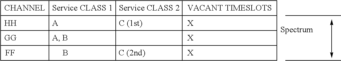
- Table 1.1 helps to illustrate some of the possible embodiments of the steps in flowchart 300 . Using Table 1.1 as an example, assume that device A, device B, and device C have already logged on and been allocated time slots in an identify of channels on the network.
- Table 1.1 indicates that device A and device B have been spread out across two channels that are different channel combinations for each device. Furthermore, these channel combinations can change to other channels within the communication spectrum of the network.
- the prior art constrained a device to operate on a single channel. Consequently, the present invention provides more flexibility and more balanced utilization of the entire communication spectrum by allowing a device to transmit on different channels. That is, the present invention allows assignment of any frequency channels within a communication spectrum to a multi-channel transmitting service class.
- device A will multiplex its double-bandwidth signal to a frequency that covers channels GG and HH while device B will multiplex its double-bandwidth signal to a frequency that covers channels FF and GG. This allows the loading to be spread out over the entire bandwidth of the multichannel network.
- the prior art would typically allocate a service class 1 device to a static and unchanging channel on the network.
- a request to log onto a network for transmission is received from a device.
- This embodiment allows a subscription service where a modem user “dials up” and logs onto the network.
- the present invention is equally applicable to a full-time connected network where a CPE device requests bandwidth using reservation-based protocol after it logs onto the network through an entry process.
- device D logs onto the network to begin communication with the hub. Device D requests bandwidth on the network on which it can transmit data.
- a loading condition of the network is determined.
- the loading is determined in one embodiment by determining the quantity of channels, as input 304 a , and the specific transmitting channels, as input 304 b , to which each existing device on a network is allocated.
- the loading condition can also utilize time slot reservation input 304 c to adjust the loading on the channels.
- This step is performed by the hub 202 as illustrated in FIG. 2 a .
- the hub utilizes data and program instructions stored in memory 230 that are processed by processor 232 to accomplish this step and other steps.
- the loading condition indicates that device A has time slots in channels GG and HH, while device B has time slots in channels NN and GG, and device C has time slots in channel FF.
- the vacancies are represented simplistically with a quantity of ‘X’s to indicate the relative amount of vacancies based on quantity of devices in each channel. This determination is just figurative, and true vacancies can be better measured by the time slot allocation, and even by the utilization of the time slots. For example, if device A is allocated time slots in two channels, but the device A is passive and not sending any data, then that channel is not being fully utilized by the devices allocated to it.
- the present invention could take advantage of this characteristic by assigning more devices to channels that have devices that rarely transmit information on the network.
- the quantity of channels, Z, required by new device is specified.
- Two inputs provide data for determining the quantity of channels.
- First, an input on the service class 307 a to which the device has subscribed is provided.
- Second, an input on the transmission capacity of the device is provided.
- the transmission capacity includes information such as number of transmitters and channel tuning range of each transmitter.
- a representative variable of “Z” is provided for clarity in the flowchart. For example, a Z value of “1” for a service class 2, e.g. as allocated to device D, would only allow transmission on a single channel. Alternatively, Z could be any number of channels less than or equal to the total number of channels in the given network.
- step 305 if the device subscribes to a high-end wide bandwidth service, but only has a fixed single channel transmitter in its device, then the device capability is the limiting factor. As another example, if the device subscribes to a low-end narrow bandwidth service, but has a multiple channel transmitter, then the subscription service is the limiting factor.
- the hub and the method should not reserve channels and time slots if the device does not have the capability to use them. In this manner, the present invention provides efficient use of network resources.
- the hub and method could reserve channels per subscription service regardless of the device capability so as to provide the immediate option for installation of an upgraded device.
- only information on the quantity of channels is provided to the device for communication on the network. In that case, the loading pattern would probably not be optimal because there is no smart allocation of the identity of where the multiple channels are located.
- step 307 specific transmitting channels on which the new device is allocated to transmit information is assigned, until the quantity, Z, of transmitting channels specified has been assigned. While the previous step determines the quantity of channels, it does not indicate how or where to place that quantity of channels within the multi-channel network. This is assuming that the quantity of channels assigned to the highest service class is less than the maximum quantity of channels in the multi-channel network. If the maximum quantity of channels assigned to the highest service class is equivalent to the maximum number of channels in the network, the device can transmit on every channel, and no identification of the channels is necessary. Otherwise, the specific channel identity will be provided to the device.
- the identity of the channels is determined according to an input indicating the desired criteria for the loading condition.
- alternative embodiments can include criteria such as uniform loading 308 a , uniform quantity of service classes 308 c in each channel, or uniform time slot assignments 308 d in the multiple channels.
- channels could be determined based on input criteria such as skewed loading, e.g. to accommodate different service classes.
- the present invention is also well suited to alternative criteria on which to identify channels for time slot allocation. For example, the network administrator can identify users according to department, priority, etc. as having certain channels. These and other criteria can be utilized by the present invention to utilize network resources in a flexible manner.
- the present invention allows a fairer and more consistent access to the network by devices because it can dynamically assign a channel to a device depending on the loading condition of the network. Consequently, the present invention more evenly utilizes the multiple channel resources and thereby provide better communication performance to the user. With uniform loading, all devices will have approximately the same probability of finding an available time slot on which to transmit. No favoritism in access to the network is shown to any service class or any device within a service class in one embodiment. However, an alternative embodiment can intentionally provide a priority scheme, or skew the loading on channels to accommodate an objective, such as priority access to a designated service class. All these changes are done at the hub, and thus, the present invention only requires inexpensive dumb devices.
- the specific channels e.g. specific location/identity of channels
- the quantity and the specific channels can be a single channel or more.
- the previous step provided a Z quantity of channels equivalent to one channel for device D.
- the specific channels to be assigned are chosen from among the multiple channels available in the network, according to one of the selection criteria. For exemplary purposes, if a uniform quantity of vacancies was the selection criteria, then the identity of the channel for device D would be channel FF because it has an additional vacancy ‘X’ over all the other channels. If more than one choice of channels would be available, the present invention envisions the use a secondary criteria to choose the channel.
- a channel for a single-channel device could be chosen such that it does not split other available channels that are adjacent to each other.
- a potential future multi-channel device would be able to more easily find a set of channels over which it can transmit.
- step 309 devices with previously assigned channels for transmission are migrated to different channels as required to provide a balanced loading of the network resources.
- This step is illustrated in the following tables, Table 1.2, Table 1.3a, and Table 1.3b. While step 309 is shown in the present embodiment to provide a superior loading condition on the network, it is not required for the present invention.
- the first table, Table 1.2 represents an initial channel assignment for hypothetical device A, device C, and device D.
- device B is not available to transmit on the network.
- device B logs onto the network and wants to transmit information.
- Device B a service class 1 device, needs two channels for transmission.
- Table 1.3a provides option #1 for assigning channels in the network. With Table 1.3a, there is no migration of existing channel assignments occurs. In other words, the original channel assignments from Table 1.2 for device A, device C, and device D remain the same. Unfortunately, the vacant timeslots column indicates the lack of balance on the channels in the network.
- a time slot allocation for the new device is determined for the specific transmitting channels.
- the time slot allocation indicates the quantity of time slots which a device can utilize for transmitting packets of information over the identity of channels which it has been allocated.
- the choice for time slot allocation is typically performed by the hub, based on service options. In one embodiment, all service classes are allocated the same quantity of time slots, while in another embodiment, the quantity can be varied.
- step 312 the time slot allocation in the specific transmitting channels is communicated to the device. After receiving this information, the device is now configured and ready to transmit on the network.
- step 314 communication from new device is received on the allocated time slots on the specific transmission channels assigned. This step essentially closes the loop for the process which started with the device logging onto the network.
- step 315 an updated loading condition is determined.
- Steps 315 through 322 are provided for ongoing traffic management and network utilization. In one embodiment, these steps are not required. In alternative embodiments, one or more of these steps can be utilized as deemed appropriate by users, the hub, a network administrator, or some other decision source. By updating the loading condition and the channel assignment, network utilization and quality of service can be maintained over time instead of just at the time when a new user logs on to the network.
- Step 315 can utilize any number of criteria for updating the loading condition.
- Flowchart 300 illustrates some of the inputs that can determine the criteria for the updated loading condition.
- inputs include the following.
- Input 316 a uses a timed-out device as a criteria. In this situation, if a device fails to communicate on the network for a certain amount of time, then it can be safely assumed that either the user has no intention of transmitting with the device, the device has experienced a failure, or etc.
- the decision about a time-out is an administrative and quality-of-service determination. If a device does not utilize its assigned channels for an extended period of time, then it essentially ties up the channels unnecessarily. These unutilized channels could be used for redistributing existing devices if there is any existing nonuniformity in the network.
- input 316 b uses a logged out criteria for updating the loading condition. That is, when a device logs out, the request to log out initiates the updated loading detrmination and subsequent steps. This can be beneficial because there might be a significant time lapse between loading conditions determined for devices logging into the network.
- Input 316 c uses time slot utilization to update the loading condition. For example, if a device is transmitting on the network, but only does so once every 60 minutes, then it could be placed on a busier channel or a channel with devices having a higher utilization so as to provide a balance.
- Input 316 d uses an intermittent time criteria to update the loading condition.
- the intermittent time can be predetermined by a network administrator or a user, or the intermittent time can be random.
- the intermittent time criteria would utilize less resources because it would not have to use a processor to constantly check for a timed-out device, etc. Rather, it would just wait until the intermittent time elapsed from the last update operation. Hence, it could be a simple and effective method, depending upon the specific application.
- Input 316 e uses time slot reservation input 304 c to adjust the loading condition. In this manner, a device that reserves a large amount of bandwidth or time slots without detrimentally affecting the devices on the same channels.
- step 318 the specific transmitting channels for the given device and for each existing device are assigned. This step is similar to step 307 . The assignment of channels continues until the quantity of transmitting channels specified for the device have been assigned.
- this step could implicitly require a device to migrate to another channel.
- a likely scenario is that an existing device assigned to specific channels has logged out of the network, and thus created a new imbalance in the loading condition of the network.
- Table 1.3b represented the existing channel assignments at an initial point in time, and device C and device D subsequently log off or are removed from the network for some reason, then an imbalance in the loading condition of the network would exist.
- the hub or server could update the loading condition, per step 315 , realize that an imbalance exists, then indicate a new channel assignment, per step 318 , using similar inputs to 308 a - 308 d .
- the result of such steps could provide a channel assignment such as the example of Table 1.4, below.
- a more balanced loading condition of the network could be obtained.
- FIG. 4 A flow chart 400 of the steps performed to provide a plurality of service classes on a network, in accordance with one embodiment of the present invention, is presented in FIG. 4 .
- the present embodiment also illustrates how the present invention accommodates multiple service classes on a given network bandwidth in flexible manner, while equating channel utilization at the same time.
- the present invention accomplishes the methods on a hub, and thus does not require expensive smart devices.
- the present invention could use a server computer rather than a hub to perform the methods described herein.
- step 402 multiple channels of communication are provided on a network.
- multiple service classes for varying bandwidths can be implemented.
- the choice of frequency channelization is an administrative decision that can have infinite possibilities. The present invention is applicable to all these choices.
- step 404 a request from each of a plurality of devices having a plurality of different service classes is received.
- the requests do not have to be received at the same time or in any type of sequence.
- different service classes could be assigned instead of requested.
- a quantity of channels for each device is allocated according to a service class.
- a high-end service class requiring a wide bandwidth is treated as a multiple of a low-end service class requiring a narrow, or just a single channel, bandwidth.
- the quantity of channels can be established to be proportionate to the level of service class desired.
- a higher service class can be allocated a narrow bandwidth, but with a high priority of access to the channels assigned for that bandwidth to provide the service desired.
- the quantity of channels is chosen from within the frequency spectrum of the communication network.
- the quantity of channels is allocated to the devices so they can transmit on the correct quantity of channels.
- the loading condition can be accommodated as described in the previous flowchart.
- the aggregate of the quantity of channels for each service class does not have to equal the total number of channels in the network. In other words, different service classes can utilize the same channels, albeit at different times. This allows the present invention to provide a flexible utilization of the multi-channel network.
- step 410 communication from the devices is received on the correct quantity of channels. This step closes the loop to the communication process whereby data is actually transmitted by the device on the network.
- CPE devices e.g. devices A-D 204 a - 204 d
- used with the present invention can have either a single frequency tunable transmitter or a multiple transmitter array. If a CPE device has a single transmitter design, it should be able to tune the full range of the frequency channels in which it is granted access. This is because efficient use of the frequency spectrum could require a user to transmit on different frequency channels at different times. For example, device C transmits a data packet 262 a on channel HH at one time, then it transmits a data packet 262 b on channel FF at a different time, for the example presented in FIG. 2 c .
- Time slots allocated to the CPE by the hub in each time frame can scatter in any of the accessible frequency channels. These time slots do not overlap in time so the theoretical maximum bandwidth achievable by a single transmitter CPE is the bandwidth of one entire frequency channel, as illustrated with data packets 262 a and 262 b . Because a single transmitter requires time to change frequencies, some guard bands in the time slots might be necessary.
- CPE devices e.g. devices A-D 204 a - 204 d
- CPE devices used with the present invention can have a multiple transmitter array. With multiple transmitters, a greater aggregate bandwidth service results that will reduce or eliminate tuning delay.
- the number of transmitters in the CPE device equals the number of accessible channels (e.g. per contracted service or per network design)
- no frequency tuning is needed for channel selections, assuming each transmitter is pretuned to transmit on one of the channels. This case would eliminate tuning delays and allow simultaneous transmission in time slots.
- the theoretical maximum bandwidth achievable becomes the bandwidth of all the frequency channels accessible by the CPE.
- the tradeoff with using the easy to implement multiple fixed channel transmitters is a higher cost than the single transmitter design. One compromise is to use fewer transmitters with a smaller frequency tuning range.
- FIG. 5 A flow chart 500 of the steps performed to dynamically change the service class of a device in a network, in accordance with one embodiment of the present invention, is presented in FIG. 5 .
- the service class for a user can be dynamically changed without requiring a new device, costly modifications to the device, or significant involvement by a network administrator. Additionally the present embodiment can create a new service class without having to rearrange the frequency channelization of the network bandwidth.
- Flowchart 500 is comprised of the following steps.
- a request to change a service class of a device is received from the device.
- a user might want to change from a narrow bandwidth service class to a wide bandwidth class because the user has a need for transmitting more data. In that situation, a higher quantity of time slots and/or channels is allocated for the higher service class, thus providing a wider bandwidth.
- the request for a change in service class could also come from an administrative program or database as a response to the user's failure to pay the service fee, etc.
- step 504 the request is verified against the transmission capability of the device and against the subscription service of the device. In this manner, the present embodiment performs a check on the validity of the devices request.
- the hub and the method should not reserve channels and time slots if the device does not have the capability to use them. Assuming the network is a subscription service, accurate billing and allocation of resources is necessary. If the network is an educational or intra-company network, then the administration could allow users to change their service on-demand and without verification.
- step 506 a loading condition is determined.
- step 508 specific transmitting channels on which the device can transmit are assigned, based on the loading condition and on the service class. Hence, a correct quantity of channels will be chosen according to the loading condition evaluated over one or more criteria, such as uniform vacancy distribution.
- criteria such as uniform vacancy distribution.
- step 510 the identify of the channels is communicated to the device.
- This step completes the method of changing the service.
- an additional step of receiving communication over the identify of channels is a natural ensuing step.
- the present embodiment provides a quick and low-cost method of changing a service class for a device. Changes can be incorporated at the hub and not at the device. Also, changes can occur dynamically and without hardware modifications. This saves the user valuable time and resources.
- FIG. 6 A flow chart 600 of the steps performed to allocate sequential alternative transmitting channels in a network, in accordance with one embodiment of the present invention, is presented in FIG. 6 .
- the present invention provides a method and apparatus to allow a new device to transmit on evenly loaded channels without upsetting the even loading. It also provides a tool for alternative transmission by a device.
- Flowchart 600 is comprised of the following steps.
- step 602 a quantity, Z, of transmitting channels for a device to transmit on a network is specified. This step can be performed using the inputs provided in step 305 of flowchart 300 .
- step 604 specific transmitting channels chosen from the total quantity of available channels upon which the device can transmit is assigned until the quantity of transmitting channels specified, Z, e.g. specified in the previous step, has been assigned.
- An input to this step for the present embodiment is a uniform loading 606 a .
- numerous other inputs, such as 308 a , 308 b , 308 c , and 308 d from flowchart 300 can be utilized to assign specific transmitting channels.
- step 608 Alternative transmitting channels from the total quantity of available channels upon which the device can transmit is assigned until the quantity of transmitting channels, Z, specified has been assigned.
- An input to step 608 can also be uniform loading 608 b , or the alternatives referred to in step 604 .
- Step 608 is illustrated in FIG. 2 c and in Table 2.1.
- Table 2.1 if device A and B were assigned the channels indicated as service class 1 users, then the network would remain unbalanced, or unevenly loaded, if device C were assigned to a single channel as a service class 2 device, e.g. a single transmitting channel device. But utilizing the present embodiment, an alternative transmitting channel can be specified for device C.
- device C is provided a specific transmitting channel of HH and an alternative transmitting channel of FF on which to sequentially and repetitively transmit. Because the quantity of channels, Z, upon which device C is allowed to transmit is a value of “1,” only one specific channel is chosen as the specific transmitting channel and the alternative transmitting channel.
- device C would transmit a first data packet on channel HH, then a second data packet on channel FF, then a third data packet on channel HH, and so on.
- the vacant timeslots are equally distributed as shown in Table 2.1.
- the order of channels transmitted on is not significant.
- the order of channels transmitted on could be tailored to the needs of a device or the network.
- the present invention is not limited to providing alternate transmission channels only to a service class 2 device.
- Devices transmitting on multiple channels can also have alternative transmission channels.
- device A could transmit on channel HH and GG for a first data packet and on channel GG and FF for a second data packet.
- more than one alternative transmission channel can be chosen.
- device C could alternatively transmit on channel HH, then channel GG, then channel FF.
- the present embodiment provides a method and apparatus to allow a new device to transmit on evenly loaded channels without upsetting the even loading.
- the present invention provides a method and apparatus that allows fairer and more consistent access to the network by devices because it can dynamically assign a channel to a device depending on the loading condition of the network. Consequently, the present invention more evenly utilizes the multiple channel resources and thereby provide better communication performance to the user.
- the present invention provides a method to dynamically change the service class for a user without requiring a new device.
- the present embodiment also illustrates how the present invention accommodates multiple service classes on a given network bandwidth in flexible manner, while equating channel utilization at the same time.
- the present invention accomplishes the methods on a hub, and thus only requires inexpensive dumb devices.
Abstract
Description
| TABLE 1.1 |
 |
| TABLE 1.2 |
| Initial Configuration for Channel Assignment |
 |
| TABLE 1.3a |
| Option #1 for Channel Assignment |
 |
| TABLE 1.3b |
| Option #2 for Channel Assignment |
 |
| TABLE 1.4 |
| Result of Updated Loading Condition and Migration of Device |
 |
| TABLE 2.1 |
 |
Claims (27)
Priority Applications (1)
| Application Number | Priority Date | Filing Date | Title |
|---|---|---|---|
| US09/348,983 US6826160B1 (en) | 1999-07-07 | 1999-07-07 | Dynamic bandwidth allocation through multi-channel time slot assignment and migration for broadband access |
Applications Claiming Priority (1)
| Application Number | Priority Date | Filing Date | Title |
|---|---|---|---|
| US09/348,983 US6826160B1 (en) | 1999-07-07 | 1999-07-07 | Dynamic bandwidth allocation through multi-channel time slot assignment and migration for broadband access |
Publications (1)
| Publication Number | Publication Date |
|---|---|
| US6826160B1 true US6826160B1 (en) | 2004-11-30 |
Family
ID=33449531
Family Applications (1)
| Application Number | Title | Priority Date | Filing Date |
|---|---|---|---|
| US09/348,983 Expired - Lifetime US6826160B1 (en) | 1999-07-07 | 1999-07-07 | Dynamic bandwidth allocation through multi-channel time slot assignment and migration for broadband access |
Country Status (1)
| Country | Link |
|---|---|
| US (1) | US6826160B1 (en) |
Cited By (30)
| Publication number | Priority date | Publication date | Assignee | Title |
|---|---|---|---|---|
| US20010047419A1 (en) * | 2000-04-07 | 2001-11-29 | Yoshihisa Gonno | Managing apparatus and method |
| US20020044537A1 (en) * | 2000-10-10 | 2002-04-18 | Radiant Networks Plc | Communications meshes |
| US20020101837A1 (en) * | 2001-01-31 | 2002-08-01 | Bender Paul E. | Method and apparatus for efficient use of communication resources in a data communication system under overload conditions |
| US20030048797A1 (en) * | 2001-08-24 | 2003-03-13 | Sandstrom Mark Henrik | System and method for maximizing the traffic delivery capacity of packet transport networks via real-time trafffic pattern based optimization of transport capacity allocation |
| US20030099256A1 (en) * | 2001-11-28 | 2003-05-29 | Feinberg Paul H. | System and method for transmitting information over multiple channels |
| US20030219020A1 (en) * | 2002-05-24 | 2003-11-27 | Hooman Honary | Method and system for distribution of session scheduling |
| US20040029579A1 (en) * | 2002-08-07 | 2004-02-12 | Kyocera Corporation | Wireless communication system |
| US20040042495A1 (en) * | 2002-08-29 | 2004-03-04 | Sandstrom Mark Henrik | Dynamically channelizable packet transport network |
| US20040174891A1 (en) * | 2003-03-07 | 2004-09-09 | Mark Sandstrom | Byte-timeslot-synchronous, dynamically switched multi-source-node data transport bus system |
| US20040208151A1 (en) * | 2002-01-18 | 2004-10-21 | Henry Haverinen | Method and apparatus for authentication in a wireless telecommunications system |
| US20040208139A1 (en) * | 2003-04-16 | 2004-10-21 | Ryuichi Iwamura | Carrier management for a network |
| US20040214581A1 (en) * | 2003-04-23 | 2004-10-28 | Davis Gregory G. | Selecting an operation mode for a device connected to a network |
| US20050013311A1 (en) * | 2003-07-18 | 2005-01-20 | Ramaprasad Samudrala | Switching device with asymmetric port speeds |
| US20050198194A1 (en) * | 2004-02-18 | 2005-09-08 | Xiotech Corporation | Method, apparatus and program storage device for providing wireless storage |
| US6957071B1 (en) * | 2001-07-18 | 2005-10-18 | Cisco Technology, Inc. | Method and system for managing wireless bandwidth resources |
| US7072354B1 (en) * | 2001-10-03 | 2006-07-04 | Cisco Technology, Inc. | Token registration of managed devices |
| US20060200598A1 (en) * | 2004-04-08 | 2006-09-07 | Janzen Jeffery W | System and method for optimizing interconnections of components in a multichip memory module |
| WO2006123275A1 (en) | 2005-05-18 | 2006-11-23 | Koninklijke Philips Electronics N.V. | Method and apparatus for enhanced uplink data transmission |
| US20070147834A1 (en) * | 2005-12-28 | 2007-06-28 | Industrial Technology Research Institute | Dynamic bandwidth allocation method with punishment mechanism in passive optical network |
| US20070274214A1 (en) * | 2003-11-18 | 2007-11-29 | Oleg Logvinov | System and method for combining synchronous and asynchronous communications on a communications network |
| US20090067345A1 (en) * | 2007-09-07 | 2009-03-12 | Kabushiki Kaisha Toshiba | Radio terminal, radio system, and program |
| US20090319714A1 (en) * | 2004-08-31 | 2009-12-24 | Ralph James | System and method for transmitting data packets in a computer system having a memory hub architecture |
| US7697431B1 (en) * | 2003-04-25 | 2010-04-13 | Cisco Technology, Inc. | Managing the bandwidths of virtual circuits when the aggregate bandwidth to an adjacent device changes |
| US20100221006A1 (en) * | 2007-11-27 | 2010-09-02 | Electronics And Telecommunications Research Institute | Apparatus and method for efficient bandwidth allocation on time division multiple access-based passive optical network (tdma-pon) |
| US7805586B2 (en) | 2002-08-29 | 2010-09-28 | Micron Technology, Inc. | System and method for optimizing interconnections of memory devices in a multichip module |
| US8015384B2 (en) * | 2004-03-08 | 2011-09-06 | Micron Technology, Inc. | Memory hub architecture having programmable lane widths |
| US20130201861A1 (en) * | 2010-12-29 | 2013-08-08 | Media Tek Singapore Pte. Ltd. | Methods for Determining a Loading of a Wireless Communications System and Communication Apparatuses Utilizing the Same |
| US8717981B1 (en) * | 2008-05-01 | 2014-05-06 | Sprint Communications Company L.P. | Priority allocation of contention resources |
| US9578515B2 (en) * | 2011-05-13 | 2017-02-21 | Qualcomm Incorporated | Methods and apparatuses for frequency spectrum sharing |
| US10660110B2 (en) * | 2016-06-11 | 2020-05-19 | Apple Inc. | Adaptive throughput and bandwidth for enhanced category of mobile devices |
Citations (15)
| Publication number | Priority date | Publication date | Assignee | Title |
|---|---|---|---|---|
| US5729534A (en) * | 1995-01-09 | 1998-03-17 | Nokia Mobile Phones Limited | Dynamic allocation of radio capacity in a TDMA system |
| US5745694A (en) * | 1994-08-30 | 1998-04-28 | Nec Corporation | Network resource reservation with admission and link control functions separated for expandability and high-speed operation |
| US5793744A (en) * | 1995-12-18 | 1998-08-11 | Nokia Telecommunications Oy | Multichannel high-speed data transfer |
| US5920571A (en) * | 1997-02-07 | 1999-07-06 | Lucent Technologies Inc. | Frequency channel and time slot assignments in broadband access networks |
| US5966374A (en) * | 1994-12-09 | 1999-10-12 | Nokia Telecommunications Oy | High-speed data transmission in mobile communication networks |
| US6018528A (en) * | 1994-04-28 | 2000-01-25 | At&T Corp | System and method for optimizing spectral efficiency using time-frequency-code slicing |
| US6031827A (en) * | 1996-10-25 | 2000-02-29 | Nokia Mobile Phones Limited | Method for radio resource control |
| US6097733A (en) * | 1997-06-13 | 2000-08-01 | Nortel Networks Corporation | System and associated method of operation for managing bandwidth in a wireless communication system supporting multimedia communications |
| US6134226A (en) * | 1998-12-31 | 2000-10-17 | Motorola, Inc. | Method and system for allocating a system resource to subscribers of a wireless communications system |
| US6262980B1 (en) * | 1997-12-02 | 2001-07-17 | At&T Corp | Dynamic resource allocation method and apparatus for broadband services in a wireless communications system |
| US6266330B1 (en) * | 1998-01-22 | 2001-07-24 | Nokia Mobile Phones Limited | Dynamic allocation of radio capacity in TDMA system |
| US6359900B1 (en) * | 1998-04-09 | 2002-03-19 | Novell, Inc. | Method and system for controlling access to a resource |
| US6377548B1 (en) * | 1997-10-14 | 2002-04-23 | Lucent Technologies Inc. | Method for admitting new connections based on measured quantities in a multiple access system for communications networks |
| US6400685B1 (en) * | 1997-04-18 | 2002-06-04 | Hyundai Electronics Ind. Co. Ltd. | Heterogenous traffic connection admission control system for ATM networks and a method thereof |
| US6438136B1 (en) * | 1998-10-09 | 2002-08-20 | Microsoft Corporation | Method for scheduling time slots in a communications network channel to support on-going video transmissions |
-
1999
- 1999-07-07 US US09/348,983 patent/US6826160B1/en not_active Expired - Lifetime
Patent Citations (16)
| Publication number | Priority date | Publication date | Assignee | Title |
|---|---|---|---|---|
| US6018528A (en) * | 1994-04-28 | 2000-01-25 | At&T Corp | System and method for optimizing spectral efficiency using time-frequency-code slicing |
| US6064662A (en) * | 1994-04-28 | 2000-05-16 | At&T Corp | System and method for optimizing spectral efficiency using time-frequency-code slicing |
| US5745694A (en) * | 1994-08-30 | 1998-04-28 | Nec Corporation | Network resource reservation with admission and link control functions separated for expandability and high-speed operation |
| US5966374A (en) * | 1994-12-09 | 1999-10-12 | Nokia Telecommunications Oy | High-speed data transmission in mobile communication networks |
| US5729534A (en) * | 1995-01-09 | 1998-03-17 | Nokia Mobile Phones Limited | Dynamic allocation of radio capacity in a TDMA system |
| US5793744A (en) * | 1995-12-18 | 1998-08-11 | Nokia Telecommunications Oy | Multichannel high-speed data transfer |
| US6031827A (en) * | 1996-10-25 | 2000-02-29 | Nokia Mobile Phones Limited | Method for radio resource control |
| US5920571A (en) * | 1997-02-07 | 1999-07-06 | Lucent Technologies Inc. | Frequency channel and time slot assignments in broadband access networks |
| US6400685B1 (en) * | 1997-04-18 | 2002-06-04 | Hyundai Electronics Ind. Co. Ltd. | Heterogenous traffic connection admission control system for ATM networks and a method thereof |
| US6097733A (en) * | 1997-06-13 | 2000-08-01 | Nortel Networks Corporation | System and associated method of operation for managing bandwidth in a wireless communication system supporting multimedia communications |
| US6377548B1 (en) * | 1997-10-14 | 2002-04-23 | Lucent Technologies Inc. | Method for admitting new connections based on measured quantities in a multiple access system for communications networks |
| US6262980B1 (en) * | 1997-12-02 | 2001-07-17 | At&T Corp | Dynamic resource allocation method and apparatus for broadband services in a wireless communications system |
| US6266330B1 (en) * | 1998-01-22 | 2001-07-24 | Nokia Mobile Phones Limited | Dynamic allocation of radio capacity in TDMA system |
| US6359900B1 (en) * | 1998-04-09 | 2002-03-19 | Novell, Inc. | Method and system for controlling access to a resource |
| US6438136B1 (en) * | 1998-10-09 | 2002-08-20 | Microsoft Corporation | Method for scheduling time slots in a communications network channel to support on-going video transmissions |
| US6134226A (en) * | 1998-12-31 | 2000-10-17 | Motorola, Inc. | Method and system for allocating a system resource to subscribers of a wireless communications system |
Non-Patent Citations (4)
| Title |
|---|
| Farnham, T. et al "Dynamic Reconfiguration and Efficient Resource Allocation for Indoor Broadband Wireless Networks" Universal Personal Communications, vol. 1, Oct. 5-9, 1998, pp. 53-57.* * |
| Koraitim, H. et al "Resource Allocation and Connection Admission Control in Satellite Networks" Selected Areas in Communications, vol. 17, Issue 2, Feb. 1999, pp. 360-372.* * |
| Koyuncu, O. et al "Dynamic Resource Assignment Using Network Flows in Wireless Data Networks" Vehicular Technology Conference, vol. 1, May 16-20, 1999, pp. 1-5.* * |
| Liu, H. et al "Efficient Bandwidth Allocation for Integrated Services in Broadband Wireless ATM Networks" Communications, Vo 3, Jun. 6-10, 1999, pp. 1896-1900. * |
Cited By (62)
| Publication number | Priority date | Publication date | Assignee | Title |
|---|---|---|---|---|
| US20010047419A1 (en) * | 2000-04-07 | 2001-11-29 | Yoshihisa Gonno | Managing apparatus and method |
| US7254635B2 (en) * | 2000-04-07 | 2007-08-07 | Sony Corporation | Apparatus and method for producing and managing data for optimizing the delivery of multimedia content |
| US20020044537A1 (en) * | 2000-10-10 | 2002-04-18 | Radiant Networks Plc | Communications meshes |
| US7251224B2 (en) * | 2000-10-10 | 2007-07-31 | Intel Corporation | Communications meshes |
| US20020101837A1 (en) * | 2001-01-31 | 2002-08-01 | Bender Paul E. | Method and apparatus for efficient use of communication resources in a data communication system under overload conditions |
| US7058031B2 (en) * | 2001-01-31 | 2006-06-06 | Qualcomm Incorporated | Method and apparatus for efficient use of communication resources in a data communication system under overload conditions |
| US6957071B1 (en) * | 2001-07-18 | 2005-10-18 | Cisco Technology, Inc. | Method and system for managing wireless bandwidth resources |
| US20030048797A1 (en) * | 2001-08-24 | 2003-03-13 | Sandstrom Mark Henrik | System and method for maximizing the traffic delivery capacity of packet transport networks via real-time trafffic pattern based optimization of transport capacity allocation |
| US7349414B2 (en) | 2001-08-24 | 2008-03-25 | Optimum Communications Services, Inc. | System and method for maximizing the traffic delivery capacity of packet transport networks via real-time traffic pattern based optimization of transport capacity allocation |
| US7072354B1 (en) * | 2001-10-03 | 2006-07-04 | Cisco Technology, Inc. | Token registration of managed devices |
| US7519077B2 (en) | 2001-10-03 | 2009-04-14 | Cisco Technology, Inc. | Token registration of managed devices |
| US20060221925A1 (en) * | 2001-10-03 | 2006-10-05 | Cisco Technology, Inc. | Token Registration of Managed Devices |
| US7940800B2 (en) * | 2001-11-28 | 2011-05-10 | Sony Corporation | System and method for transmitting information over multiple channels |
| US20030099256A1 (en) * | 2001-11-28 | 2003-05-29 | Feinberg Paul H. | System and method for transmitting information over multiple channels |
| US20060268935A1 (en) * | 2001-11-28 | 2006-11-30 | Sony Electronics Inc. | System and method for transmitting information over multiple channels |
| US7110421B2 (en) * | 2001-11-28 | 2006-09-19 | Sony Corporation | System and method for transmitting information over multiple channels |
| US20040208151A1 (en) * | 2002-01-18 | 2004-10-21 | Henry Haverinen | Method and apparatus for authentication in a wireless telecommunications system |
| US8045530B2 (en) * | 2002-01-18 | 2011-10-25 | Nokia Corporation | Method and apparatus for authentication in a wireless telecommunications system |
| US20030219020A1 (en) * | 2002-05-24 | 2003-11-27 | Hooman Honary | Method and system for distribution of session scheduling |
| US7242687B2 (en) * | 2002-05-24 | 2007-07-10 | Intel Corporation | Method and system for distribution of session scheduling |
| US20040029579A1 (en) * | 2002-08-07 | 2004-02-12 | Kyocera Corporation | Wireless communication system |
| US9036597B2 (en) * | 2002-08-07 | 2015-05-19 | Kyocera Corporation | Wireless communication system |
| US8194703B2 (en) * | 2002-08-07 | 2012-06-05 | Kyocera Corporation | Wireless communication system |
| US20120307807A1 (en) * | 2002-08-07 | 2012-12-06 | Kyocera Corporation | Wireless communication system |
| US20110055478A1 (en) * | 2002-08-29 | 2011-03-03 | Ryan Kevin J | System and method for optimizing interconnections of memory devices in a multichip module |
| US8190819B2 (en) | 2002-08-29 | 2012-05-29 | Micron Technology, Inc. | System and method for optimizing interconnections of memory devices in a multichip module |
| US20040042495A1 (en) * | 2002-08-29 | 2004-03-04 | Sandstrom Mark Henrik | Dynamically channelizable packet transport network |
| US7836252B2 (en) | 2002-08-29 | 2010-11-16 | Micron Technology, Inc. | System and method for optimizing interconnections of memory devices in a multichip module |
| US7805586B2 (en) | 2002-08-29 | 2010-09-28 | Micron Technology, Inc. | System and method for optimizing interconnections of memory devices in a multichip module |
| US7333511B2 (en) * | 2002-08-29 | 2008-02-19 | Optimum Communications Services, Inc. | Dynamically channelizable packet transport network |
| US20040174891A1 (en) * | 2003-03-07 | 2004-09-09 | Mark Sandstrom | Byte-timeslot-synchronous, dynamically switched multi-source-node data transport bus system |
| US7558260B2 (en) | 2003-03-07 | 2009-07-07 | Optimum Communication Services, Inc. | Byte-timeslot-synchronous, dynamically switched multi-source-node data transport bus system |
| US7423992B2 (en) * | 2003-04-16 | 2008-09-09 | Sony Corporation | Time slot and carrier frequency allocation in a network |
| US20040208139A1 (en) * | 2003-04-16 | 2004-10-21 | Ryuichi Iwamura | Carrier management for a network |
| US20040214581A1 (en) * | 2003-04-23 | 2004-10-28 | Davis Gregory G. | Selecting an operation mode for a device connected to a network |
| US7697431B1 (en) * | 2003-04-25 | 2010-04-13 | Cisco Technology, Inc. | Managing the bandwidths of virtual circuits when the aggregate bandwidth to an adjacent device changes |
| US20050013311A1 (en) * | 2003-07-18 | 2005-01-20 | Ramaprasad Samudrala | Switching device with asymmetric port speeds |
| US7324537B2 (en) * | 2003-07-18 | 2008-01-29 | Intel Corporation | Switching device with asymmetric port speeds |
| US20070274214A1 (en) * | 2003-11-18 | 2007-11-29 | Oleg Logvinov | System and method for combining synchronous and asynchronous communications on a communications network |
| US20050198194A1 (en) * | 2004-02-18 | 2005-09-08 | Xiotech Corporation | Method, apparatus and program storage device for providing wireless storage |
| US8775764B2 (en) | 2004-03-08 | 2014-07-08 | Micron Technology, Inc. | Memory hub architecture having programmable lane widths |
| US9274991B2 (en) | 2004-03-08 | 2016-03-01 | Micron Technology, Inc. | Memory hub architecture having programmable lane widths |
| US8015384B2 (en) * | 2004-03-08 | 2011-09-06 | Micron Technology, Inc. | Memory hub architecture having programmable lane widths |
| US7870329B2 (en) | 2004-04-08 | 2011-01-11 | Micron Technology, Inc. | System and method for optimizing interconnections of components in a multichip memory module |
| US8438329B2 (en) | 2004-04-08 | 2013-05-07 | Micron Technology, Inc. | System and method for optimizing interconnections of components in a multichip memory module |
| US20060200598A1 (en) * | 2004-04-08 | 2006-09-07 | Janzen Jeffery W | System and method for optimizing interconnections of components in a multichip memory module |
| US20090319714A1 (en) * | 2004-08-31 | 2009-12-24 | Ralph James | System and method for transmitting data packets in a computer system having a memory hub architecture |
| US7949803B2 (en) | 2004-08-31 | 2011-05-24 | Micron Technology, Inc. | System and method for transmitting data packets in a computer system having a memory hub architecture |
| US8346998B2 (en) | 2004-08-31 | 2013-01-01 | Micron Technology, Inc. | System and method for transmitting data packets in a computer system having a memory hub architecture |
| WO2006123275A1 (en) | 2005-05-18 | 2006-11-23 | Koninklijke Philips Electronics N.V. | Method and apparatus for enhanced uplink data transmission |
| US20080198800A1 (en) * | 2005-05-18 | 2008-08-21 | Koninklijke Philips Electronics, N.V. | Method and Apparatus for Enhanced Uplink Data Transmission |
| US8488453B2 (en) | 2005-05-18 | 2013-07-16 | Koninklijke Philips Electronics N.V. | Method and apparatus for enhanced uplink data transmission |
| CN101176317B (en) * | 2005-05-18 | 2011-09-07 | 皇家飞利浦电子股份有限公司 | Reinforced ascending data transmission method and its device |
| US7843965B2 (en) | 2005-12-28 | 2010-11-30 | Industrial Technology Research Institute | Dynamic bandwidth allocation method with punishment mechanism in passive optical network |
| US20070147834A1 (en) * | 2005-12-28 | 2007-06-28 | Industrial Technology Research Institute | Dynamic bandwidth allocation method with punishment mechanism in passive optical network |
| US20090067345A1 (en) * | 2007-09-07 | 2009-03-12 | Kabushiki Kaisha Toshiba | Radio terminal, radio system, and program |
| US20100221006A1 (en) * | 2007-11-27 | 2010-09-02 | Electronics And Telecommunications Research Institute | Apparatus and method for efficient bandwidth allocation on time division multiple access-based passive optical network (tdma-pon) |
| US8717981B1 (en) * | 2008-05-01 | 2014-05-06 | Sprint Communications Company L.P. | Priority allocation of contention resources |
| US20130201861A1 (en) * | 2010-12-29 | 2013-08-08 | Media Tek Singapore Pte. Ltd. | Methods for Determining a Loading of a Wireless Communications System and Communication Apparatuses Utilizing the Same |
| US9781616B2 (en) * | 2010-12-29 | 2017-10-03 | Mediatek Singapore Pte. Ltd. | Methods for determining a loading of a wireless communications system and communication apparatuses utilizing the same |
| US9578515B2 (en) * | 2011-05-13 | 2017-02-21 | Qualcomm Incorporated | Methods and apparatuses for frequency spectrum sharing |
| US10660110B2 (en) * | 2016-06-11 | 2020-05-19 | Apple Inc. | Adaptive throughput and bandwidth for enhanced category of mobile devices |
Similar Documents
| Publication | Publication Date | Title |
|---|---|---|
| US6826160B1 (en) | Dynamic bandwidth allocation through multi-channel time slot assignment and migration for broadband access | |
| US6577610B1 (en) | Flex slotted Aloha transmission system and method | |
| US6937580B2 (en) | Apportioning bandwidth capacity in communication switching systems | |
| US6819930B1 (en) | Apparatus and method for use in allocating a channel resource in wireless multiple access communications systems | |
| US6882623B1 (en) | Multi-level scheduling method for multiplexing packets in a communications network | |
| US5594738A (en) | Time slot allocation method | |
| CA2333729C (en) | Dynamic bandwidth allocation in cdma system | |
| US9240834B2 (en) | Method and apparatus for providing open loop bandwidth allocation | |
| US7933249B2 (en) | Grade of service and fairness policy for bandwidth reservation system | |
| US6570847B1 (en) | Method and system for network traffic rate control based on fractional tokens | |
| US20020036985A1 (en) | Two-dimensional scheduling scheme for a broadband wireless access system | |
| US8824416B2 (en) | Method and a radio base station in a communication network system | |
| KR20030058174A (en) | Mobile Communacation System and Method of Selecting a Server at the Mobile Communication System | |
| US6532220B1 (en) | System and method for efficient channel assignment | |
| JP2009520437A (en) | Resource scheduling in cellular systems | |
| US20060072581A1 (en) | Method and apparatus for providing quality of service guarantees using stateful monitoring of network load | |
| WO2019045827A1 (en) | Spectrum sharing with switching of tier levels between networks and/or devices | |
| KR20010022518A (en) | Method and apparatus for allocating resources between queued and non-queued services | |
| JPH0738612B2 (en) | Control device in satellite communication system | |
| KR20020027226A (en) | Communication system and resource assigning method therefor | |
| JP2003087282A (en) | Circuit, method and program for assigning dynamic band and recording medium | |
| CN1315124A (en) | Method and apparatus for allocating channels in a mobile telecommunications system supporting both packet and circuit switched traffic | |
| US7120116B2 (en) | Method and apparatus for assigning packet resources of wireless local loop (WLL) | |
| KR20110052561A (en) | Method of allocating channel time for variable bit rate (vbr) traffic, apparatus for processing data and method thereof | |
| RU2320086C2 (en) | Methods and device for transmitting user data using an information channel |
Legal Events
| Date | Code | Title | Description |
|---|---|---|---|
| AS | Assignment |
Owner name: 3COM CORPORATION, CALIFORNIA Free format text: ASSIGNMENT OF ASSIGNORS INTEREST;ASSIGNORS:WANG, PETER S.;YU, BEN Y.;REEL/FRAME:010102/0405;SIGNING DATES FROM 19990628 TO 19990702 |
|
| STCF | Information on status: patent grant |
Free format text: PATENTED CASE |
|
| FEPP | Fee payment procedure |
Free format text: PAYOR NUMBER ASSIGNED (ORIGINAL EVENT CODE: ASPN); ENTITY STATUS OF PATENT OWNER: LARGE ENTITY |
|
| FPAY | Fee payment |
Year of fee payment: 4 |
|
| AS | Assignment |
Owner name: HEWLETT-PACKARD COMPANY, CALIFORNIA Free format text: MERGER;ASSIGNOR:3COM CORPORATION;REEL/FRAME:024630/0820 Effective date: 20100428 |
|
| AS | Assignment |
Owner name: HEWLETT-PACKARD COMPANY, CALIFORNIA Free format text: CORRECTIVE ASSIGNMENT TO CORRECT THE SEE ATTACHED;ASSIGNOR:3COM CORPORATION;REEL/FRAME:025039/0844 Effective date: 20100428 |
|
| AS | Assignment |
Owner name: HEWLETT-PACKARD DEVELOPMENT COMPANY, L.P., TEXAS Free format text: ASSIGNMENT OF ASSIGNORS INTEREST;ASSIGNOR:HEWLETT-PACKARD COMPANY;REEL/FRAME:027329/0044 Effective date: 20030131 |
|
| AS | Assignment |
Owner name: HEWLETT-PACKARD DEVELOPMENT COMPANY, L.P., TEXAS Free format text: CORRECTIVE ASSIGNMENT PREVIUOSLY RECORDED ON REEL 027329 FRAME 0001 AND 0044;ASSIGNOR:HEWLETT-PACKARD COMPANY;REEL/FRAME:028911/0846 Effective date: 20111010 |
|
| FPAY | Fee payment |
Year of fee payment: 8 |
|
| AS | Assignment |
Owner name: HEWLETT PACKARD ENTERPRISE DEVELOPMENT LP, TEXAS Free format text: ASSIGNMENT OF ASSIGNORS INTEREST;ASSIGNOR:HEWLETT-PACKARD DEVELOPMENT COMPANY, L.P.;REEL/FRAME:037079/0001 Effective date: 20151027 |
|
| FPAY | Fee payment |
Year of fee payment: 12 |