US6560611B1 - Method, apparatus, and article of manufacture for a network monitoring system - Google Patents
Method, apparatus, and article of manufacture for a network monitoring system Download PDFInfo
- Publication number
- US6560611B1 US6560611B1 US09/416,079 US41607999A US6560611B1 US 6560611 B1 US6560611 B1 US 6560611B1 US 41607999 A US41607999 A US 41607999A US 6560611 B1 US6560611 B1 US 6560611B1
- Authority
- US
- United States
- Prior art keywords
- service
- software
- data record
- information
- monitoring
- Prior art date
- Legal status (The legal status is an assumption and is not a legal conclusion. Google has not performed a legal analysis and makes no representation as to the accuracy of the status listed.)
- Expired - Lifetime
Links
Images


Classifications
-
- H—ELECTRICITY
- H04—ELECTRIC COMMUNICATION TECHNIQUE
- H04L—TRANSMISSION OF DIGITAL INFORMATION, e.g. TELEGRAPHIC COMMUNICATION
- H04L43/00—Arrangements for monitoring or testing data switching networks
-
- H—ELECTRICITY
- H04—ELECTRIC COMMUNICATION TECHNIQUE
- H04L—TRANSMISSION OF DIGITAL INFORMATION, e.g. TELEGRAPHIC COMMUNICATION
- H04L41/00—Arrangements for maintenance, administration or management of data switching networks, e.g. of packet switching networks
- H04L41/06—Management of faults, events, alarms or notifications
- H04L41/069—Management of faults, events, alarms or notifications using logs of notifications; Post-processing of notifications
-
- H—ELECTRICITY
- H04—ELECTRIC COMMUNICATION TECHNIQUE
- H04L—TRANSMISSION OF DIGITAL INFORMATION, e.g. TELEGRAPHIC COMMUNICATION
- H04L41/00—Arrangements for maintenance, administration or management of data switching networks, e.g. of packet switching networks
- H04L41/50—Network service management, e.g. ensuring proper service fulfilment according to agreements
- H04L41/5003—Managing SLA; Interaction between SLA and QoS
- H04L41/5009—Determining service level performance parameters or violations of service level contracts, e.g. violations of agreed response time or mean time between failures [MTBF]
-
- G—PHYSICS
- G06—COMPUTING; CALCULATING OR COUNTING
- G06F—ELECTRIC DIGITAL DATA PROCESSING
- G06F11/00—Error detection; Error correction; Monitoring
- G06F11/30—Monitoring
- G06F11/34—Recording or statistical evaluation of computer activity, e.g. of down time, of input/output operation ; Recording or statistical evaluation of user activity, e.g. usability assessment
- G06F11/3466—Performance evaluation by tracing or monitoring
- G06F11/3495—Performance evaluation by tracing or monitoring for systems
-
- H—ELECTRICITY
- H04—ELECTRIC COMMUNICATION TECHNIQUE
- H04L—TRANSMISSION OF DIGITAL INFORMATION, e.g. TELEGRAPHIC COMMUNICATION
- H04L43/00—Arrangements for monitoring or testing data switching networks
- H04L43/06—Generation of reports
- H04L43/065—Generation of reports related to network devices
-
- H—ELECTRICITY
- H04—ELECTRIC COMMUNICATION TECHNIQUE
- H04L—TRANSMISSION OF DIGITAL INFORMATION, e.g. TELEGRAPHIC COMMUNICATION
- H04L43/00—Arrangements for monitoring or testing data switching networks
- H04L43/08—Monitoring or testing based on specific metrics, e.g. QoS, energy consumption or environmental parameters
- H04L43/0805—Monitoring or testing based on specific metrics, e.g. QoS, energy consumption or environmental parameters by checking availability
- H04L43/0817—Monitoring or testing based on specific metrics, e.g. QoS, energy consumption or environmental parameters by checking availability by checking functioning
-
- Y—GENERAL TAGGING OF NEW TECHNOLOGICAL DEVELOPMENTS; GENERAL TAGGING OF CROSS-SECTIONAL TECHNOLOGIES SPANNING OVER SEVERAL SECTIONS OF THE IPC; TECHNICAL SUBJECTS COVERED BY FORMER USPC CROSS-REFERENCE ART COLLECTIONS [XRACs] AND DIGESTS
- Y10—TECHNICAL SUBJECTS COVERED BY FORMER USPC
- Y10S—TECHNICAL SUBJECTS COVERED BY FORMER USPC CROSS-REFERENCE ART COLLECTIONS [XRACs] AND DIGESTS
- Y10S707/00—Data processing: database and file management or data structures
- Y10S707/99941—Database schema or data structure
- Y10S707/99944—Object-oriented database structure
- Y10S707/99945—Object-oriented database structure processing
-
- Y—GENERAL TAGGING OF NEW TECHNOLOGICAL DEVELOPMENTS; GENERAL TAGGING OF CROSS-SECTIONAL TECHNOLOGIES SPANNING OVER SEVERAL SECTIONS OF THE IPC; TECHNICAL SUBJECTS COVERED BY FORMER USPC CROSS-REFERENCE ART COLLECTIONS [XRACs] AND DIGESTS
- Y10—TECHNICAL SUBJECTS COVERED BY FORMER USPC
- Y10S—TECHNICAL SUBJECTS COVERED BY FORMER USPC CROSS-REFERENCE ART COLLECTIONS [XRACs] AND DIGESTS
- Y10S707/00—Data processing: database and file management or data structures
- Y10S707/99941—Database schema or data structure
- Y10S707/99948—Application of database or data structure, e.g. distributed, multimedia, or image
Definitions
- This invention relates generally to network monitoring systems and, more specifically, a method for monitoring mission critical network infrastructures and providing application support for client networks.
- a mission critical network infrastructure is a network that runs an electronic commerce site or provides real time data to a plurality of users. These network infrastructures generally must remain online at all times and can afford little or no down time.
- Devices on these networks usually are comprised of many different types and brands of network devices, such as Windows NT servers, Unix servers, routers, and terminal servers. For example, if, per chance, the Unix billing system were to fail, quite possibly, an entire electronic commerce site could lose large sums of money.
- a nonstandard port may be used, such as port 2058 .
- devices that use standard ports sometimes use different methods to indicate availability.
- a router may use well-known SNMP traps to indicate availability, whereas a well-known telnet server provides a “login” prompt when a client connects to a port 23 .
- a network contains 50 telnet servers, even though they respond the same way, monitoring each one becomes an arduous task.
- Methods and systems consistent with the present invention solve the limitations of current monitoring systems by automatically and completely monitoring various networks devices and services. Specifically, a network monitoring system monitors all services and conditions on various networks. Moreover, the network monitoring system provides advance warnings of potential failures by examining log files and may diagnose any problems that may surface.
- a method for monitoring a network with at least one service on the network.
- the method spawns a process for each one of the services to monitor, and monitors a service with the spawned process.
- the method notifies an accounting server.
- FIG. 1 depicts a data processing system suitable for practicing methods and systems consistent with the present invention
- FIG. 2A depicts a more detailed diagram of an RMS server depicted in FIG. 1;
- FIG. 2B depicts a more detailed diagram of a CAS server depicted in FIG. 1;
- FIG. 3 depicts a more detailed diagram of a device depicted in FIG. 1;
- FIG. 4 depicts an overview flow chart of the steps performed by the data processing system of FIG. 1 when monitoring in accordance with methods and systems consistent with the present invention
- FIG. 5A depicts a flow chart of the steps performed by the initiation process of FIG. 4;
- FIG. 5B depicts a flow chart of the steps performed by the monitoring process of FIG. 4;
- FIG. 5C depicts a flow chart of the steps performed by the dispatch process of FIG. 4;
- FIG. 6 depicts a ticket in accordance with methods and systems consistent with the present invention
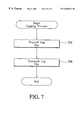
- FIG. 7 depicts a flow chart of the steps performed by the logging process in accordance with methods and systems consistent with the present invention.
- FIG. 8 depicts a sample report created by the reporting software in accordance with methods and systems of the present invention.
- the network monitoring system contains many Remote Monitoring System (RMS) servers and a Central Accounting System (CAS) server.
- RMS Remote Monitoring System
- CAS Central Accounting System
- An RMS server is placed at a client site and is responsible for monitoring various network services, such as http, ftp, dns, nntp, smtp, snmp, environmental conditions, such as power status, temperature, humidity, and security services, such as authentication, intrusion detection, firewalls, encryption, unauthorized devices on the network and network traffic.
- the RMS server contains software that may communicate with the service or sensors.
- the software spawns a copy of itself for each service or sensor that the RMS is configured to monitor.
- the RMS server may examine various log files to send to the CAS for dispatch.
- the RMS server may receive a log file by a remote logging program located on the monitored device.
- Each spawned software continuously monitors the corresponding service. If the software detects that a service is not responding or that an anomaly has occurred with the service, the RMS server sends information regarding the non-responding service or a daily network traffic report to the NOS as a ticket.
- a ticket is a data record containing information about the service, such as location, severity of the problem, and time of occurrence.
- the ticket may be an SGML document.
- the RMS server may communicate with the NOC through the Internet. However, if the RMS server is unable to contact the NOC through the Internet, the RMS server may use some other out-of-band means, such as a direct telephone connection.
- a CAS server determines the nature of the problem, and notifies the proper personnel. For example, a technician may be notified by a page or electronic mail.
- the CAS may also store all tickets for later retrieval, such as for creating reports.
- an additional RMS server may be placed at the NOC to monitor RMS servers at client sites.
- This RMS server monitors the connection between each RMS server at client sites and the NOC. If a problem is detected with one of the RMS servers at a client site, as mentioned before, the CAS may notify the proper personnel.
- a uniform standard data format may be employed, such as Standard Generalized Markup Language (SGML) or Extended Markup Language (XML). These languages provide efficient and flexible formats for storing data. In particular, unlike standard databases, the format can be modified quickly and easily to accommodate system updates and improvements.
- any computer language may be used, such as Practical Extraction and Report Language (PERL).
- PERL is object-oriented, and provides a module for parsing and accessing SGML or XML data.
- FIG. 1 depicts a data processing system 100 suitable for practicing methods and systems consistent with the present invention.
- Data processing system 100 includes a Remote Monitoring System (RMS) Server 104 and a Central Accounting System (CAS) Server 106 at the network operation site 102 .
- RMS server 104 monitors the status of the RMS server at client site 120 .
- CAS server 106 receives and stores tickets and passes the ticket to diagnose the problem and dispatch personnel if necessary.
- RMS server 122 At client site 120 is a RMS server 122 and various devices 124 , such as routers, servers, or hubs.
- RMS server 104 and CAS server 106 communicate with RMS server 122 through network 102 , such as the Internet.
- RMS server 122 submits information regarding the status of device 124 to CAS server 106 .
- network 102 such as the Internet.
- RMS server 122 submits information regarding the status of device 124 to CAS server 106 .
- RMS server 122 may also communicate with network operation site 102 with an out-of-band communication network 130 , such as a POTS line.
- CAS server 106 or RMS server 104 may be included at client site 120 .
- FIG. 2A depicts a more detailed diagram of RMS 122 .
- RMS 122 contains a memory 220 , a secondary storage device 232 , a central processing unit (“CPU”) 238 , an input device 240 , a video display 242 , and environmental sensors 244 .
- Memory 220 includes informer engine 222 that responds to information queries from various softwares associated with informer engine 222 .
- informer engine 222 includes forker software 224 that uses well-known Unix fork commands to spawn copies of other softwares, checker software 226 that monitors devices and communicates with informer engine 222 to receive additional information regarding the device, sender software that spawns deliverer software 230 when a problem on client network 120 is detected, and deliverer software 230 that transmits a message to CAS 106 when a problem is detected on client network 120 .
- Each software communicates with the informer engine 222 though various queries. To do so, the software places the query through an interprocess communication facility such as the well-known Unix types or message queues.
- the interprocess communication facility allows for efficient communication between active softwares. For example, a query from checker software 226 to informer engine 222 contains information required by the informer engine 222 to fulfill the query. The informer engine 222 responds to the query with the relevant information requested, sending this information to the process that sent the query though the interprocess communication facility.
- An environmental sensor is a sensor to monitor the environment, such as a temperature sensor.
- Secondary storage device 232 contains a database 234 that interfaces with informer engine 222 .
- Database 232 contains a device file 236 that includes configuration information for RMS server 104 and specific information regarding each service to be monitored at client site 120 .
- device file 236 may contain the IP address of the device 124 , the IRQ of environmental sensor 244 , or errors to locate when parsing log files associated with each service.
- FIG. 2B depicts a more detailed diagram of CAS server 106 .
- CAS server 106 contains a memory 246 , a secondary storage device 256 , a central processing unit (“CPU”) 264 , an input device 266 , and a video display 268 .
- Memory 246 includes accounting engine 248 that responds to information queries from various softwares.
- Accounting engine 248 includes receiver software 250 that receives tickets from RMS server 122 and places them in CMS database 258 , notifier software 252 that analyzes CMS database 258 at regular intervals and, if data indicates a problem it notifies the proper personnel to resolve the problem, and reporter software 254 that generates reports, such as billing information, or the total number of problems recorded by RMS 122 .
- Secondary storage device 256 contains a database 258 that interfaces with accounting engine 248 .
- CAS database 258 contains an administrator file 262 that contains information regarding technicians and sales personnel that should be notified when a ticket is received, and a ticket file 260 that contains pending tickets.
- FIG. 3 depicts a more detailed diagram of device 124 .
- Device 124 contains a memory 320 , a secondary storage device 330 , a central processing unit (“CPU”) 340 , an input device 350 , and a video display 360 .
- Memory 320 includes a service 322 that provides access capabilities to device 124 .
- service 322 may be a well-known HTTPD service running on port 80 .
- Service 322 may also be, for example, a routing deamon or SNMP interface.
- Memory 320 also includes logger program 324 that transmits various log files on device 124 when requested by RMS server 122 or CAS server 106 .
- Secondary storage device 330 contains a log file 332 that records various events on device 124 .
- log file 332 may be a HTTPD access file, or a security access file.
- aspects of the present invention are described as being stored in memory, one skilled in the art will appreciate that these aspects may be stored on or read from other computer-readable media, such as secondary storage devices, like hard disks, floppy disks and CD-ROM; a carrier wave received from a network like the Internet; or other forms of ROM or RAM. Additionally, although specific components and programs of RMS server 122 and CAS server 106 have been described, one skilled in the art will appreciate that these may contain additional or different components or programs.
- FIG. 4 depicts a flow chart of the steps performed by Network Monitoring System 100 .
- the network monitoring process is initiated by the initiation process (step 402 ).
- the initiation process comprises loading of various softwares into memory on RMS server 122 and CAS server 106 .
- the monitoring process is started (step 404 ).
- This process entails monitoring various network services in devices 124 , environmental conditional at the client site, and security services with a checker software.
- the checker software notifies network operation site 102 .
- network operation site 102 determines an appropriate action, and dispatches a message containing possible solutions to the proper personnel (step 406 ).
- Network monitoring system 100 provides an automatic monitoring system that requires little or no user intervention to detect and diagnose any problem at client site 120 .
- initiation process 402 is initiated, for example, by informer engine 222 loading into memory (step 502 ).
- informer engine may be loaded from secondary storage device 430 to memory 420 .
- Memory 420 contains enough space for informer engine 222 to execute and load necessary software and files.
- informer engine 222 may be loaded by other means, such as a well-known PCMCIA memory flash card.
- informer engine 222 is initiated (step 504 ) and executes forker software 224 and sender software 228 (step 506 ). Forker software 224 and sender software 228 remain in memory with informer engine 222 . Also, informer engine 222 reads and loads device file 236 from database 234 into memory 420 .
- Forker software 224 begins execution by transmitting a query to informer engine 222 requesting a list of all services on device 124 to monitor at client site 120 (step 508 ). Informer engine 222 obtains this information by reading device file 234 . Once obtained, informer engine 222 transmits the requested information to forker software 224 . For example, if device file 234 contains an entry to monitor web and mail services on device 124 , informer engine 222 may transmit a responses to forker software 224 that includes the port number of the web and mail services, and the physical address of device 124 . Informer engine 222 may transmit the response as follows:
- forker software 224 spawns one checker software 226 for each service to monitor (step 510 ). Forker software 224 spawns multiple copies of the checker software so that RMS 122 may simultaneously monitor all services, thereby reducing the total time to completely monitor client site 120 . For example, referring to the list mentioned above, forker software 224 spawns two copies of checker software 226 to monitor port 80 and port 25 at address 200 . 2 . 8 . 10 . Forker software 224 transmits the address of device 124 and port to the corresponding spawned checker software 226 . One skilled in the art will appreciate that other attributes may be used to identify the device and service, such as a protocol address, or machine address. Also, forker software 224 spawns a checker software to monitor environmental sensors 244 on RMS server 122 .
- Each spawned checker software transmits a query, similar to the forker query, to informer engine 222 (step 512 ).
- the query is a request for additional details regarding the service to monitor on device 124 or sensor information.
- the query includes the address and port of the service checker software 226 will be monitoring.
- the query may include information regarding the log file to obtain from device 124 .
- checker software 226 may need to know a list of errors to look for in the log file.
- checker software 226 may parse the log file for multiple well-known ICMP packets or invalid routes in a routing log file.
- informer engine 222 obtains this information from device file 234 and transmits the information to checker software 226 . For example, if checker software 226 requests additional information on the web service in device 200 . 2 . 8 . 10 , informer engine 222 may transmit a responses to checker software 226 that includes the directory to store tickets, the frequency at which to query each service, the duration of monitoring, and the contact person. Informer engine 222 may transmit the response as follows:
- sender software 228 transmits a query to informer 222 that includes a request for a list of delivery methods and a corresponding data-key to be used when spawning deliverer software 230 and notifying CAS 106 from client site 120 (step 514 ).
- a data-key is a unique character string, such as “INTERNET” that is unique to a delivery method.
- Sender software 228 requires a delivery method and a data-key to spawn a new deliverer software 230 .
- informer engine 222 responds with the data-keys to be used to send tickets to NOS 102 , along with the order in which to try them.
- Sender software 228 attempts each delivery method using a deliverer software 230 in turn until one succeeds in sending a ticket to the NOS 102 .
- the first delivery method typically tried by deliverer software 230 is the Internet.
- deliverer software 230 may attempt a second delivery method, such as a well-known POTS line.
- Informer engine 222 may transmit the response as follows to sender software 228 :
- Each delivery method is associated with a data-key which provides different information.
- the Internet delivery method requires an IP-address and port-number
- the POTS delivery method requires a phone-number, login, and password.
- CAS server 106 initiates accounting engine 248 . Similar to the initiation of RMS 122 , accounting engine 248 executes receiver software 250 and notifier software 252 (step 516 ). Receiver software 246 then queries accounting engine 248 for the location to place an incoming ticket. Accounting engine 248 reads administrator file 262 from database 258 for this information. Receiver software 246 may also receive information about notifier software 252 and where to notify personnel.
- monitoring process 504 may begin.
- checker software 226 may perform various techniques. In a first technique, checker software 226 may determine when a service 322 on device 124 does not respond (step 520 ). For example, checker software 226 may periodically open a web service on device 124 . If the web service does not respond within 30 seconds, for example, checker software 226 determines that a problem exists with the web service. Checker software 226 may use any well-known method to check the availability of service 322 on device 124 , such as ping, nmap, finger, or telnet.
- checker software 226 may monitor environmental sensors 244 . For example, if the temperature is too high, checker software 226 may determine that a problem exists with the environment. This information may be an indication that a problem exists and can be used as an indicator to larger problems.
- checker software 226 may obtain log file 332 that corresponds to service 322 on device 124 . In doing so, checker software 226 may parse log file 332 and locate a potential problem. For example, checker software 226 may receive a log file from a router that indicates that a particular route is not functioning. Although the router is responding, the log file would indicate an error.
- FIG. 6 depicts an exemplary ticket 600 consistent with methods and systems of the present invention.
- Ticket 600 is created with SGML.
- Ticket 600 contains information that describes the problem with device 124 at a level of detail necessary for a technician to find the problem and correct it.
- ticket 600 contains SGML tags 602 to identify a client site, the device location, the device address, and the service name that is malfunctioning.
- SGML tags 602 to identify a client site, the device location, the device address, and the service name that is malfunctioning.
- ticket 600 may contain additional information and also may be written in different formats, such as comma delimited text, or database format.
- checker software 226 transmits ticket 600 embedded in a query to sender software 228 (step 526 ).
- Sender software 228 then delivers ticket 600 to CAS 106 .
- sender software 228 spawns deliverer software 230 and sends ticket 600 embedded in a query and a data-key to deliverer software 230 (step 528 ).
- Deliverer software 230 uses the data-key to query informer engine 222 for information particular to the corresponding delivery method of the ticket (step 530 ). Once delivery software 230 receives the delivery method information from informer engine 222 , deliverer software 230 sends ticket 600 to CAS 106 using the corresponding delivery method (step 532 ).
- deliverer software 230 at client site 120 may transmit ticket 600 to CAS 106 over network 110 .
- deliverer software 230 may connect to the receiver software 250 on CAS 106 using well-known sockets on the Internet.
- deliverer software 230 may transmit ticket 600 to CAS 106 by other means, such as out-of-band communications, e-mail, ftp or HTTP.
- deliverer software 230 waits for a confirmation from CAS 106 that the ticket has been received (step 534 ).
- CAS 106 may confirm receipt by transmitting a reply response to the deliverer software 230 .
- deliverer software 230 indicates a failed delivery attempt to the sender software 228 .
- sender software 228 spawns a new deliverer software 230 with a different method than used by the previous deliverer software 230 .
- deliverer software 230 waits for a confirmation from CAS 106 that the ticket has been received (step 534 ). Steps 528 - 534 may repeat until a confirmation is received from CAS 106 . If, ultimately, a confirmation is never received, ticket 600 may be stored on secondary storage device 232 until communication with CAS 106 is re-established. When communications is reestablished, sender software 230 may attempt to deliver the ticket again.
- dispatch process 406 may begin.
- the dispatch process begins.
- the dispatch process begins, for example, by receiving ticket 600 at CAS 106 (step 536 ).
- receiver process 250 parses the ticket and uses the information in the ticket to query accounting engine 248 for information on where to place the pending ticket (step 538 ).
- receiver software 250 may query accounting engine 248 with the IP address and port number of the service that is nonresponsive.
- Accounting engine 248 queries administrator file 262 for information regarding the service and responds with the location for ticket 600 in ticket file 260 .
- receiver process 250 spawns a copy of notifier software 252 (step 540 ).
- Notifier software 252 uses the information in the ticket to requery accounting engine 248 (step 542 ).
- Accounting engine 248 queries administrator file 262 and responds with the technical or sales personnel to be notified of the pending ticket and the method of notification to use. For example, if notifier software 252 queries accounting engine 248 with the IP and port address of a nonresponsive web service, accounting engine 248 may query administrator file 262 for a notification method. In administrator file 262 may be a preferred contact method for web services. Accounting engine 248 then responds to notifier software 252 with the notification information.
- notifier software 252 receives the information from accounting engine 248 , notifier software 252 immediately notifies the proper personnel (step 544 ). For example, if accounting engine 248 informs notifier software 252 that a Web Administrator should be notified by e-mail, notifier software 252 transmits an e-mail message to the Web administrator and includes all ticket information.
- sender software 228 may also obtain log files 332 corresponding to service 322 on device 124 . By obtaining log files associated with a particular service, CAS 106 may diagnose the problem with the service. As shown in FIG. 7, the logging process is initiated by sender software 228 transmitting a message to logger program 324 requesting a particular log file 332 (step 702 ). For example, if a web service is unavaibale on device 124 , in addition to transmitting a ticket to CAS 106 , sender software 228 may connect to port 5150 on device 124 and transmit a query to logger program 324 for the HTTP log files. This added feature provides necessary information to help diagnose the problem.
- logger program 324 locates the appropriate log file and transmits a portion of log file 332 to sender software 228 (step 704 ). For example, if device 124 is a well-known NT server, logger program 324 may transmit an event file. Once skilled in the art will appreciate that logger program 324 may transmit multiple log files or specific sections of any given log file.
- the reporter software 254 is an additional software used to audit and extract information from ticket file 260 to generate a report.
- Reporter software 260 analyzes CAS database 256 and generates reports, such as total tickets created, or billing information.
- FIG. 8 depicts a sample report created by reporting software 254 in accordance with methods and systems of the present invention.
- reports may be used to help detect patterns in problems experienced by a device which may in turn lead to the detection of larger scale problems, such intrusion or security breeches or network traffic anomalies. For example, if a series of tickets indicate that a security log file on an NT server has a flood of ICMP packets, a report may be created to locate all of the tickets that indicate this problem.
- reporter software 254 may access ans parse ticket file 260 with well-known programs written in languages such as SQL.
- RMS 122 may also contain a well-known web interface.
- the web interface provides the ability to create a manual ticket or a request for service.
- a user at client site 120 may use a web page on RMS 122 that can be accessed via any standard browser, such as Netscape Navigator.
- the web page is written in the well known Hypertext Markup Language, HTML, and can access PERL scripts located on a standard web server, such as the Apache web server.
- the information needed to be displayed by the Web page is obtained by querying informer engine 222 .
- a ticket submitted by the Web page is similar to a ticket generated by checker software 226 .
- Methods and systems consistent with the present invention solve the limitations of current monitoring systems by automatically and completely monitoring various networks devices and services. Specifically, a network monitoring system monitors all services and conditions on various network. Moreover, the network monitoring system may provide an advance warning of potential failures and may diagnose any problems that may surface. Methods and systems consistent with the present invention can work well with systems written in C++, Perl, C or other programming languages such as Java.
Abstract
Description
Claims (17)
Priority Applications (3)
| Application Number | Priority Date | Filing Date | Title |
|---|---|---|---|
| US09/416,079 US6560611B1 (en) | 1998-10-13 | 1999-09-23 | Method, apparatus, and article of manufacture for a network monitoring system |
| US10/428,154 US7490066B2 (en) | 1998-10-13 | 2003-05-02 | Method, apparatus, and article of manufacture for a network monitoring system |
| US12/344,243 US8473606B2 (en) | 1998-10-13 | 2008-12-25 | Network monitoring system |
Applications Claiming Priority (2)
| Application Number | Priority Date | Filing Date | Title |
|---|---|---|---|
| US10397398P | 1998-10-13 | 1998-10-13 | |
| US09/416,079 US6560611B1 (en) | 1998-10-13 | 1999-09-23 | Method, apparatus, and article of manufacture for a network monitoring system |
Related Child Applications (2)
| Application Number | Title | Priority Date | Filing Date |
|---|---|---|---|
| US10/428,154 Continuation US7490066B2 (en) | 1998-10-13 | 2003-05-02 | Method, apparatus, and article of manufacture for a network monitoring system |
| US10/428,154 Continuation-In-Part US7490066B2 (en) | 1998-10-13 | 2003-05-02 | Method, apparatus, and article of manufacture for a network monitoring system |
Publications (1)
| Publication Number | Publication Date |
|---|---|
| US6560611B1 true US6560611B1 (en) | 2003-05-06 |
Family
ID=26801050
Family Applications (3)
| Application Number | Title | Priority Date | Filing Date |
|---|---|---|---|
| US09/416,079 Expired - Lifetime US6560611B1 (en) | 1998-10-13 | 1999-09-23 | Method, apparatus, and article of manufacture for a network monitoring system |
| US10/428,154 Expired - Fee Related US7490066B2 (en) | 1998-10-13 | 2003-05-02 | Method, apparatus, and article of manufacture for a network monitoring system |
| US12/344,243 Expired - Fee Related US8473606B2 (en) | 1998-10-13 | 2008-12-25 | Network monitoring system |
Family Applications After (2)
| Application Number | Title | Priority Date | Filing Date |
|---|---|---|---|
| US10/428,154 Expired - Fee Related US7490066B2 (en) | 1998-10-13 | 2003-05-02 | Method, apparatus, and article of manufacture for a network monitoring system |
| US12/344,243 Expired - Fee Related US8473606B2 (en) | 1998-10-13 | 2008-12-25 | Network monitoring system |
Country Status (1)
| Country | Link |
|---|---|
| US (3) | US6560611B1 (en) |
Cited By (49)
| Publication number | Priority date | Publication date | Assignee | Title |
|---|---|---|---|---|
| US20020042721A1 (en) * | 2000-10-05 | 2002-04-11 | Alcatel | Network management client |
| US20020059078A1 (en) * | 2000-09-01 | 2002-05-16 | Valdes Alfonso De Jesus | Probabilistic alert correlation |
| US20020120776A1 (en) * | 2000-12-23 | 2002-08-29 | Eggebraaten Thomas John | Computer system, method, and business method for automating business-to-business communications |
| US20020157021A1 (en) * | 2000-07-14 | 2002-10-24 | Stephen Sorkin | System and method for computer security using multiple cages |
| US20020162017A1 (en) * | 2000-07-14 | 2002-10-31 | Stephen Sorkin | System and method for analyzing logfiles |
| US20030061129A1 (en) * | 2001-09-25 | 2003-03-27 | Stephen Todd | Mediation device for scalable storage service |
| US20030097445A1 (en) * | 2001-11-20 | 2003-05-22 | Stephen Todd | Pluggable devices services and events for a scalable storage service architecture |
| US20030115073A1 (en) * | 2001-12-19 | 2003-06-19 | Stephen Todd | Workflow database for scalable storage service |
| US20030150909A1 (en) * | 2001-12-28 | 2003-08-14 | Kimberly-Clark Worldwide, Inc. | Quality management by validating a bill of materials in event-based product manufacturing |
| WO2003067365A2 (en) * | 2001-06-12 | 2003-08-14 | Digex, Inc. | Automated message handling system and process |
| US20030155415A1 (en) * | 2001-12-28 | 2003-08-21 | Kimberly-Clark Worldwide, Inc. | Communication between machines and feed-forward control in event-based product manufacturing |
| US20030158795A1 (en) * | 2001-12-28 | 2003-08-21 | Kimberly-Clark Worldwide, Inc. | Quality management and intelligent manufacturing with labels and smart tags in event-based product manufacturing |
| US20040003071A1 (en) * | 2002-06-28 | 2004-01-01 | Microsoft Corporation | Parental controls customization and notification |
| US20040042589A1 (en) * | 2002-08-29 | 2004-03-04 | Grooms Paul C. | System and method for automatically reporting call tickets |
| US20050235360A1 (en) * | 1999-11-18 | 2005-10-20 | Secureworks, Inc. | Method and system for remotely configuring and monitoring a communication device |
| US20060013367A1 (en) * | 2001-06-12 | 2006-01-19 | Mci, Inc. | Automated message handling system |
| US20060041681A1 (en) * | 2000-12-18 | 2006-02-23 | Shaw Parsing, Llc | Techniques for delivering personalized content with a real-time routing network |
| US20060075279A1 (en) * | 2004-08-17 | 2006-04-06 | Shaw Parsing, Llc | Techniques for upstream failure detection and failure recovery |
| US20060117318A1 (en) * | 2004-08-17 | 2006-06-01 | Shaw Parsing, Llc | Modular event-driven processing |
| US20060150105A1 (en) * | 2005-01-03 | 2006-07-06 | International Business Machines Corporation | Application status board mitigation system and method |
| US7181487B1 (en) * | 2000-07-07 | 2007-02-20 | Schneider Automation Inc. | Method and system for transmitting and activating an application requesting human intervention in an automation network |
| US20070061460A1 (en) * | 2005-03-24 | 2007-03-15 | Jumpnode Systems,Llc | Remote access |
| US20070061883A1 (en) * | 1999-07-14 | 2007-03-15 | Symantec Corporation | System and method for generating fictitious content for a computer |
| US20070157315A1 (en) * | 1999-08-30 | 2007-07-05 | Symantec Corporation | System and method for using timestamps to detect attacks |
| US20070239822A1 (en) * | 2000-12-18 | 2007-10-11 | Timothy Tuttle | Asynchronous messaging using a node specialization architecture in the dynamic routing network |
| US7293084B1 (en) * | 1999-11-25 | 2007-11-06 | Nec Corporation | Network contents managing system |
| US20070294747A1 (en) * | 2002-09-23 | 2007-12-20 | Wimetrics Corporation | System and method for wireless local area network monitoring and intrusion detection |
| US20080034084A1 (en) * | 2006-08-04 | 2008-02-07 | International Business Machines Corporation | Method, system and program product for monitoring client programs in a client-server environment |
| CN100370762C (en) * | 2006-03-08 | 2008-02-20 | 华为技术有限公司 | Method device and system for processing warning message |
| US20080141349A1 (en) * | 1999-07-14 | 2008-06-12 | Symantec Corporation | System and method for computer security |
| US20090064331A1 (en) * | 1999-07-14 | 2009-03-05 | Symantec Corporation | System and method for preventing detection of a selected process running on a computer |
| US20090132673A1 (en) * | 2007-11-18 | 2009-05-21 | Sprigg Stephen A | System and method for transmitting alert locations to navigational devices |
| US7552056B2 (en) | 2001-09-25 | 2009-06-23 | Emc Corporation | Scalable storage service registration application |
| US7584387B1 (en) * | 2000-12-22 | 2009-09-01 | Medin David T | Method and system for extending the functionality of an environmental monitor for an industrial personal computer |
| US7587484B1 (en) * | 2001-10-18 | 2009-09-08 | Microsoft Corporation | Method and system for tracking client software use |
| US20090287815A1 (en) * | 2008-05-19 | 2009-11-19 | Electrodata, Inc. | Systems and Methods for Monitoring A Remote Network |
| US20100106537A1 (en) * | 2008-10-23 | 2010-04-29 | Kei Yuasa | Detecting Potentially Unauthorized Objects Within An Enterprise |
| US7937370B2 (en) | 2000-09-22 | 2011-05-03 | Axeda Corporation | Retrieving data from a server |
| US7966418B2 (en) | 2003-02-21 | 2011-06-21 | Axeda Corporation | Establishing a virtual tunnel between two computer programs |
| US8055758B2 (en) | 2000-07-28 | 2011-11-08 | Axeda Corporation | Reporting the state of an apparatus to a remote computer |
| US8060886B2 (en) | 2002-04-17 | 2011-11-15 | Axeda Corporation | XML scripting of SOAP commands |
| US8065397B2 (en) | 2006-12-26 | 2011-11-22 | Axeda Acquisition Corporation | Managing configurations of distributed devices |
| US8108543B2 (en) | 2000-09-22 | 2012-01-31 | Axeda Corporation | Retrieving data from a server |
| US8370479B2 (en) | 2006-10-03 | 2013-02-05 | Axeda Acquisition Corporation | System and method for dynamically grouping devices based on present device conditions |
| US8406119B2 (en) | 2001-12-20 | 2013-03-26 | Axeda Acquisition Corporation | Adaptive device-initiated polling |
| TWI396060B (en) * | 2008-06-16 | 2013-05-11 | Mitsubishi Electric Corp | Plant monitoring control system |
| US8478861B2 (en) | 2007-07-06 | 2013-07-02 | Axeda Acquisition Corp. | Managing distributed devices with limited connectivity |
| US8505024B2 (en) | 2000-12-18 | 2013-08-06 | Shaw Parsing Llc | Storing state in a dynamic content routing network |
| CN110888889A (en) * | 2018-08-17 | 2020-03-17 | 阿里巴巴集团控股有限公司 | Data information updating method, device and equipment |
Families Citing this family (76)
| Publication number | Priority date | Publication date | Assignee | Title |
|---|---|---|---|---|
| US6694364B1 (en) * | 2000-06-16 | 2004-02-17 | Cisco Technology, Inc. | System and method for suppressing out-of-order side-effect alarms in heterogeneous integrated wide area data and telecommunication networks |
| US20020069217A1 (en) * | 2000-12-04 | 2002-06-06 | Hua Chen | Automatic, multi-stage rich-media content creation using a framework based digital workflow - systems, methods and program products |
| US7299202B2 (en) * | 2001-02-07 | 2007-11-20 | Exalt Solutions, Inc. | Intelligent multimedia e-catalog |
| US7099938B2 (en) * | 2001-03-23 | 2006-08-29 | Hewlett-Packard Development Company, L.P. | Method, computer system, and computer program product for monitoring services of an information technology environment |
| US7792948B2 (en) * | 2001-03-30 | 2010-09-07 | Bmc Software, Inc. | Method and system for collecting, aggregating and viewing performance data on a site-wide basis |
| US7461369B2 (en) * | 2001-03-30 | 2008-12-02 | Bmc Software, Inc. | Java application response time analyzer |
| US7506047B2 (en) * | 2001-03-30 | 2009-03-17 | Bmc Software, Inc. | Synthetic transaction monitor with replay capability |
| US20030041097A1 (en) * | 2001-07-11 | 2003-02-27 | Alexander Tormasov | Distributed transactional network storage system |
| JP3766332B2 (en) * | 2002-02-12 | 2006-04-12 | アライドテレシスホールディングス株式会社 | Management device and program |
| US7093013B1 (en) * | 2002-06-19 | 2006-08-15 | Alcatel | High availability system for network elements |
| US7865764B2 (en) * | 2002-10-01 | 2011-01-04 | Rackmaster Systems, Inc. | Remote chassis monitoring system |
| US20040158627A1 (en) * | 2003-02-11 | 2004-08-12 | Thornton Barry W. | Computer condition detection system |
| US7246156B2 (en) * | 2003-06-09 | 2007-07-17 | Industrial Defender, Inc. | Method and computer program product for monitoring an industrial network |
| US7568025B2 (en) | 2003-06-27 | 2009-07-28 | Bank Of America Corporation | System and method to monitor performance of different domains associated with a computer system or network |
| US9350752B2 (en) | 2003-07-01 | 2016-05-24 | Securityprofiling, Llc | Anti-vulnerability system, method, and computer program product |
| US20070112941A2 (en) * | 2003-07-01 | 2007-05-17 | Securityprofiling, Inc. | Client capture of vulnerability data |
| US8984644B2 (en) | 2003-07-01 | 2015-03-17 | Securityprofiling, Llc | Anti-vulnerability system, method, and computer program product |
| US9100431B2 (en) | 2003-07-01 | 2015-08-04 | Securityprofiling, Llc | Computer program product and apparatus for multi-path remediation |
| US20070113272A2 (en) | 2003-07-01 | 2007-05-17 | Securityprofiling, Inc. | Real-time vulnerability monitoring |
| US9118710B2 (en) | 2003-07-01 | 2015-08-25 | Securityprofiling, Llc | System, method, and computer program product for reporting an occurrence in different manners |
| US9118709B2 (en) | 2003-07-01 | 2015-08-25 | Securityprofiling, Llc | Anti-vulnerability system, method, and computer program product |
| US9118711B2 (en) | 2003-07-01 | 2015-08-25 | Securityprofiling, Llc | Anti-vulnerability system, method, and computer program product |
| US9118708B2 (en) | 2003-07-01 | 2015-08-25 | Securityprofiling, Llc | Multi-path remediation |
| CA2444834A1 (en) * | 2003-10-10 | 2005-04-10 | N-Able Technologies Inc. | Multi-network monitoring architecture |
| DE10354938B4 (en) * | 2003-11-25 | 2008-01-31 | Fujitsu Siemens Computers Gmbh | Automated management data processing system and method for automated management of a data processing system |
| US7392300B2 (en) * | 2004-01-08 | 2008-06-24 | Hewlett-Packard Development Company, L.P. | Method and system for modelling a communications network |
| US7606894B2 (en) * | 2004-01-27 | 2009-10-20 | Ricoh Company, Ltd. | Method and system for determining the type of status information to extract from networked devices in a multi-protocol remote monitoring system |
| US7651530B2 (en) * | 2004-03-22 | 2010-01-26 | Honeywell International Inc. | Supervision of high value assets |
| US7636365B2 (en) * | 2004-05-13 | 2009-12-22 | Korea Advanced Institute Of Science And Technology (Kaist) | Smart digital modules and smart digital wall surfaces combining the same, and context aware interactive multimedia system using the same and operation method thereof |
| US7310742B2 (en) * | 2004-06-30 | 2007-12-18 | Intel Corporation | Method and apparatus for performing disk diagnostics and repairs on remote clients |
| US7886295B2 (en) * | 2005-02-17 | 2011-02-08 | International Business Machines Corporation | Connection manager, method, system and program product for centrally managing computer applications |
| US20060200705A1 (en) * | 2005-03-07 | 2006-09-07 | International Business Machines Corporation | Method, system and program product for monitoring a heartbeat of a computer application |
| US7979854B1 (en) * | 2005-09-29 | 2011-07-12 | Cisco Technology, Inc. | Method and system for upgrading software or firmware by using drag and drop mechanism |
| US20070097398A1 (en) * | 2005-10-27 | 2007-05-03 | Walton Andrew C | Provision and use of device images that are associated with one or more relationships specifying how to navigate between the images |
| US8836717B2 (en) * | 2005-10-27 | 2014-09-16 | Hewlett-Packard Development Company, L.P. | System, method and utility to format images retrieved from a device |
| US7631269B2 (en) * | 2005-10-27 | 2009-12-08 | Hewlett-Packard Development Company, L.P. | Utility, method and device providing vector images that may be updated to reflect the physical states of configurable components of a device |
| US7724985B2 (en) * | 2005-10-27 | 2010-05-25 | Hewlett-Packard Development Company, L.P. | Device storing vector image with embedded image style identifier, and methods and utilities for formatting a device image with image style attributes |
| US7710428B2 (en) * | 2005-10-27 | 2010-05-04 | Hewlett-Packard Development Company, L.P. | Method and apparatus for filtering the display of vectors in a vector image |
| US20070097149A1 (en) * | 2005-10-27 | 2007-05-03 | Walton Andrew C | Utility, method and device providing vector images that may be updated to reflect the presence of removable components of a device |
| US20070098270A1 (en) * | 2005-10-27 | 2007-05-03 | Walton Andrew C | Device storing vector image with handles identifying portions of the device, and methods and computer programs to aid in mapping or correlating portions of an image retrieved from a device with portions of the device |
| US20070097137A1 (en) * | 2005-10-27 | 2007-05-03 | Walton Andrew C | Utilities, methods and device providing vector images that may be updated to reflect the status of a device |
| US7882430B2 (en) * | 2005-10-27 | 2011-02-01 | Hewlett-Packard Development Company, L.P. | Utility, method and device providing vector images that may be formatted for display in different locales |
| US8018469B2 (en) * | 2005-10-27 | 2011-09-13 | Hewlett-Packard Development Company, L.P. | System, device, method and utility to convert images retrieved from a device to a format supported by a device management tool |
| US7765293B2 (en) * | 2005-12-21 | 2010-07-27 | International Business Machines Corporation | System and algorithm for monitoring event specification and event subscription models |
| US20070208840A1 (en) * | 2006-03-03 | 2007-09-06 | Nortel Networks Limited | Graphical user interface for network management |
| TWI310131B (en) * | 2006-03-24 | 2009-05-21 | Wistron Corp | Remote monitoring method with event-triggered warning capability |
| US7831694B2 (en) * | 2006-05-11 | 2010-11-09 | Arvind Wadhawan | Transfer of electrical data with auto-discovery of system configuration |
| US8014767B1 (en) * | 2006-11-06 | 2011-09-06 | Sprint Communications Company L.P. | Wireless communication network with software update monitoring and notification |
| US8990378B2 (en) * | 2007-07-05 | 2015-03-24 | Interwise Ltd. | System and method for collection and analysis of server log files |
| US9515538B2 (en) * | 2008-05-29 | 2016-12-06 | Nidec Motor Corporation | Dynamoelectric machine assemblies having memory for use by external devices |
| US9779234B2 (en) * | 2008-06-18 | 2017-10-03 | Symantec Corporation | Software reputation establishment and monitoring system and method |
| US20100062409A1 (en) * | 2008-09-10 | 2010-03-11 | International Business Machines Corporation | Method of developing and provisioning it state information of complex systems utilizing a question/answer paradigm |
| US8413111B2 (en) * | 2008-10-02 | 2013-04-02 | Actiance, Inc. | Techniques for dynamic updating and loading of custom application detectors |
| US8504687B2 (en) * | 2008-11-26 | 2013-08-06 | Telecom Italia S.P.A. | Application data flow management in an IP network |
| US8239709B2 (en) * | 2009-08-12 | 2012-08-07 | Apple Inc. | Managing extrinsic processes |
| US9177266B2 (en) * | 2011-02-25 | 2015-11-03 | Ancestry.Com Operations Inc. | Methods and systems for implementing ancestral relationship graphical interface |
| US9032014B2 (en) * | 2012-02-06 | 2015-05-12 | Sap Se | Diagnostics agents for managed computing solutions hosted in adaptive environments |
| US9542250B2 (en) * | 2012-09-07 | 2017-01-10 | International Business Machines Corporation | Distributed maintenance mode control |
| RU2537274C1 (en) * | 2013-08-19 | 2014-12-27 | Иван Викторович Анзин | Integrated system of audit and monitoring of information security of local computer network of enterprise |
| US10735246B2 (en) | 2014-01-10 | 2020-08-04 | Ent. Services Development Corporation Lp | Monitoring an object to prevent an occurrence of an issue |
| US10366101B2 (en) | 2014-04-15 | 2019-07-30 | Splunk Inc. | Bidirectional linking of ephemeral event streams to creators of the ephemeral event streams |
| US10360196B2 (en) | 2014-04-15 | 2019-07-23 | Splunk Inc. | Grouping and managing event streams generated from captured network data |
| US10127273B2 (en) | 2014-04-15 | 2018-11-13 | Splunk Inc. | Distributed processing of network data using remote capture agents |
| US10462004B2 (en) | 2014-04-15 | 2019-10-29 | Splunk Inc. | Visualizations of statistics associated with captured network data |
| US10700950B2 (en) | 2014-04-15 | 2020-06-30 | Splunk Inc. | Adjusting network data storage based on event stream statistics |
| US9923767B2 (en) * | 2014-04-15 | 2018-03-20 | Splunk Inc. | Dynamic configuration of remote capture agents for network data capture |
| US10523521B2 (en) | 2014-04-15 | 2019-12-31 | Splunk Inc. | Managing ephemeral event streams generated from captured network data |
| US9762443B2 (en) | 2014-04-15 | 2017-09-12 | Splunk Inc. | Transformation of network data at remote capture agents |
| US10693742B2 (en) | 2014-04-15 | 2020-06-23 | Splunk Inc. | Inline visualizations of metrics related to captured network data |
| US11086897B2 (en) | 2014-04-15 | 2021-08-10 | Splunk Inc. | Linking event streams across applications of a data intake and query system |
| US11281643B2 (en) | 2014-04-15 | 2022-03-22 | Splunk Inc. | Generating event streams including aggregated values from monitored network data |
| US9565510B2 (en) | 2015-05-28 | 2017-02-07 | At&T Mobility Ii Llc | Coordinating wireless communication network access via multiple logic capable databases |
| US10374915B1 (en) * | 2015-06-29 | 2019-08-06 | Amazon Technologies, Inc. | Metrics processing service |
| US10616253B2 (en) * | 2017-11-13 | 2020-04-07 | International Business Machines Corporation | Anomaly detection using cognitive computing |
| US11127057B2 (en) | 2017-12-08 | 2021-09-21 | Exalt Solutions, Inc. | Intelligent multimedia e-catalog |
| CN110290002B (en) * | 2019-06-27 | 2023-08-01 | 北京百度网讯科技有限公司 | Updating method, terminal and electronic equipment |
Citations (5)
| Publication number | Priority date | Publication date | Assignee | Title |
|---|---|---|---|---|
| US5590181A (en) * | 1993-10-15 | 1996-12-31 | Link Usa Corporation | Call-processing system and method |
| US5999908A (en) * | 1992-08-06 | 1999-12-07 | Abelow; Daniel H. | Customer-based product design module |
| US6115040A (en) * | 1997-09-26 | 2000-09-05 | Mci Communications Corporation | Graphical user interface for Web enabled applications |
| US6185598B1 (en) * | 1998-02-10 | 2001-02-06 | Digital Island, Inc. | Optimized network resource location |
| US6370583B1 (en) * | 1998-08-17 | 2002-04-09 | Compaq Information Technologies Group, L.P. | Method and apparatus for portraying a cluster of computer systems as having a single internet protocol image |
Family Cites Families (15)
| Publication number | Priority date | Publication date | Assignee | Title |
|---|---|---|---|---|
| GB9019017D0 (en) * | 1990-08-31 | 1990-10-17 | Hewlett Packard Co | Network fault analysis |
| US5793954A (en) * | 1995-12-20 | 1998-08-11 | Nb Networks | System and method for general purpose network analysis |
| US5796633A (en) * | 1996-07-12 | 1998-08-18 | Electronic Data Systems Corporation | Method and system for performance monitoring in computer networks |
| US5958010A (en) * | 1997-03-20 | 1999-09-28 | Firstsense Software, Inc. | Systems and methods for monitoring distributed applications including an interface running in an operating system kernel |
| US6181736B1 (en) * | 1997-03-25 | 2001-01-30 | Nxi Communications, Inc. | Network communication system |
| US6247149B1 (en) * | 1997-10-28 | 2001-06-12 | Novell, Inc. | Distributed diagnostic logging system |
| CN1293478C (en) * | 1999-06-30 | 2007-01-03 | 倾向探测公司 | Method and apparatus for monitoring traffic in a network |
| US6658585B1 (en) * | 1999-10-07 | 2003-12-02 | Andrew E. Levi | Method and system for simple network management protocol status tracking |
| US7089300B1 (en) * | 1999-10-18 | 2006-08-08 | Apple Computer, Inc. | Method and apparatus for administering the operating system of a net-booted environment |
| US7580996B1 (en) * | 2000-05-31 | 2009-08-25 | International Business Machines Corporation | Method and system for dynamic update of an application monitoring agent using a non-polling mechanism |
| US7120678B2 (en) * | 2001-02-27 | 2006-10-10 | Hewlett-Packard Development Company, L.P. | Method and apparatus for configurable data collection on a computer network |
| US8543681B2 (en) * | 2001-10-15 | 2013-09-24 | Volli Polymer Gmbh Llc | Network topology discovery systems and methods |
| US7580991B2 (en) * | 2002-01-07 | 2009-08-25 | Sun Microsystems, Inc. | Methods and apparatuses to configure and deploy servers |
| US7082460B2 (en) * | 2002-04-19 | 2006-07-25 | Axeda Corporation | Configuring a network gateway |
| US7127597B2 (en) * | 2002-09-24 | 2006-10-24 | Novell, Inc. | Mechanism for controlling boot decisions from a network policy directory based on client profile information |
-
1999
- 1999-09-23 US US09/416,079 patent/US6560611B1/en not_active Expired - Lifetime
-
2003
- 2003-05-02 US US10/428,154 patent/US7490066B2/en not_active Expired - Fee Related
-
2008
- 2008-12-25 US US12/344,243 patent/US8473606B2/en not_active Expired - Fee Related
Patent Citations (5)
| Publication number | Priority date | Publication date | Assignee | Title |
|---|---|---|---|---|
| US5999908A (en) * | 1992-08-06 | 1999-12-07 | Abelow; Daniel H. | Customer-based product design module |
| US5590181A (en) * | 1993-10-15 | 1996-12-31 | Link Usa Corporation | Call-processing system and method |
| US6115040A (en) * | 1997-09-26 | 2000-09-05 | Mci Communications Corporation | Graphical user interface for Web enabled applications |
| US6185598B1 (en) * | 1998-02-10 | 2001-02-06 | Digital Island, Inc. | Optimized network resource location |
| US6370583B1 (en) * | 1998-08-17 | 2002-04-09 | Compaq Information Technologies Group, L.P. | Method and apparatus for portraying a cluster of computer systems as having a single internet protocol image |
Cited By (106)
| Publication number | Priority date | Publication date | Assignee | Title |
|---|---|---|---|---|
| US20080141349A1 (en) * | 1999-07-14 | 2008-06-12 | Symantec Corporation | System and method for computer security |
| US7827605B2 (en) | 1999-07-14 | 2010-11-02 | Symantec Corporation | System and method for preventing detection of a selected process running on a computer |
| US20070061883A1 (en) * | 1999-07-14 | 2007-03-15 | Symantec Corporation | System and method for generating fictitious content for a computer |
| US8549640B2 (en) | 1999-07-14 | 2013-10-01 | Symantec Corporation | System and method for computer security |
| US20090064331A1 (en) * | 1999-07-14 | 2009-03-05 | Symantec Corporation | System and method for preventing detection of a selected process running on a computer |
| US7854005B2 (en) | 1999-07-14 | 2010-12-14 | Symantec Corporation | System and method for generating fictitious content for a computer |
| US8578490B2 (en) | 1999-08-30 | 2013-11-05 | Symantec Corporation | System and method for using timestamps to detect attacks |
| US20070157315A1 (en) * | 1999-08-30 | 2007-07-05 | Symantec Corporation | System and method for using timestamps to detect attacks |
| US7512981B2 (en) * | 1999-11-18 | 2009-03-31 | Secureworks, Inc. | Method and system for remotely configuring and monitoring a communication device |
| US20050235360A1 (en) * | 1999-11-18 | 2005-10-20 | Secureworks, Inc. | Method and system for remotely configuring and monitoring a communication device |
| US7293084B1 (en) * | 1999-11-25 | 2007-11-06 | Nec Corporation | Network contents managing system |
| US7181487B1 (en) * | 2000-07-07 | 2007-02-20 | Schneider Automation Inc. | Method and system for transmitting and activating an application requesting human intervention in an automation network |
| US6907533B2 (en) * | 2000-07-14 | 2005-06-14 | Symantec Corporation | System and method for computer security using multiple cages |
| US20020162017A1 (en) * | 2000-07-14 | 2002-10-31 | Stephen Sorkin | System and method for analyzing logfiles |
| US20020157021A1 (en) * | 2000-07-14 | 2002-10-24 | Stephen Sorkin | System and method for computer security using multiple cages |
| US8055758B2 (en) | 2000-07-28 | 2011-11-08 | Axeda Corporation | Reporting the state of an apparatus to a remote computer |
| US8898294B2 (en) | 2000-07-28 | 2014-11-25 | Axeda Corporation | Reporting the state of an apparatus to a remote computer |
| US7917393B2 (en) * | 2000-09-01 | 2011-03-29 | Sri International, Inc. | Probabilistic alert correlation |
| US20020059078A1 (en) * | 2000-09-01 | 2002-05-16 | Valdes Alfonso De Jesus | Probabilistic alert correlation |
| US7937370B2 (en) | 2000-09-22 | 2011-05-03 | Axeda Corporation | Retrieving data from a server |
| US8762497B2 (en) | 2000-09-22 | 2014-06-24 | Axeda Corporation | Retrieving data from a server |
| US10069937B2 (en) | 2000-09-22 | 2018-09-04 | Ptc Inc. | Retrieving data from a server |
| US8108543B2 (en) | 2000-09-22 | 2012-01-31 | Axeda Corporation | Retrieving data from a server |
| US20020042721A1 (en) * | 2000-10-05 | 2002-04-11 | Alcatel | Network management client |
| US10860567B2 (en) | 2000-12-18 | 2020-12-08 | Zarbaña Digital Fund Llc | Storing state in a dynamic content routing network |
| US8505024B2 (en) | 2000-12-18 | 2013-08-06 | Shaw Parsing Llc | Storing state in a dynamic content routing network |
| US8407722B2 (en) | 2000-12-18 | 2013-03-26 | Shaw Parsing L.L.C. | Asynchronous messaging using a node specialization architecture in the dynamic routing network |
| US7930362B2 (en) | 2000-12-18 | 2011-04-19 | Shaw Parsing, Llc | Techniques for delivering personalized content with a real-time routing network |
| US9613076B2 (en) | 2000-12-18 | 2017-04-04 | Zarbaña Digital Fund Llc | Storing state in a dynamic content routing network |
| US20060041681A1 (en) * | 2000-12-18 | 2006-02-23 | Shaw Parsing, Llc | Techniques for delivering personalized content with a real-time routing network |
| US7814225B2 (en) | 2000-12-18 | 2010-10-12 | Rumelhart Karl E | Techniques for delivering personalized content with a real-time routing network |
| US9071648B2 (en) | 2000-12-18 | 2015-06-30 | Shaw Parsing L.L.C. | Asynchronous messaging using a node specialization architecture in the dynamic routing network |
| US20070239822A1 (en) * | 2000-12-18 | 2007-10-11 | Timothy Tuttle | Asynchronous messaging using a node specialization architecture in the dynamic routing network |
| US20110161458A1 (en) * | 2000-12-18 | 2011-06-30 | Shaw Parsing, Llc | Techniques For Delivering Personalized Content With A Real-Time Routing Network |
| US7584387B1 (en) * | 2000-12-22 | 2009-09-01 | Medin David T | Method and system for extending the functionality of an environmental monitor for an industrial personal computer |
| US6928487B2 (en) * | 2000-12-23 | 2005-08-09 | International Business Machines Corporation | Computer system, method, and business method for automating business-to-business communications |
| US20020120776A1 (en) * | 2000-12-23 | 2002-08-29 | Eggebraaten Thomas John | Computer system, method, and business method for automating business-to-business communications |
| US7424735B2 (en) | 2001-04-23 | 2008-09-09 | Symantec Corporation | System and method for computer security using multiple cages |
| US20050071684A1 (en) * | 2001-04-23 | 2005-03-31 | Symantec Corporation | System and method for computer security using multiple cages |
| US20060013367A1 (en) * | 2001-06-12 | 2006-01-19 | Mci, Inc. | Automated message handling system |
| US20080189376A1 (en) * | 2001-06-12 | 2008-08-07 | Verizon Business Network Services Inc. | Automated message handling system and process |
| WO2003067365A3 (en) * | 2001-06-12 | 2003-10-02 | Digex Inc | Automated message handling system and process |
| WO2003067365A2 (en) * | 2001-06-12 | 2003-08-14 | Digex, Inc. | Automated message handling system and process |
| US8364800B2 (en) | 2001-06-12 | 2013-01-29 | Verizon Business Network Services Inc. | Automated message handling system and process |
| US8700781B2 (en) | 2001-06-12 | 2014-04-15 | Verizon Business Global Llc | Automated processing of service requests using structured messaging protocols |
| US8055555B2 (en) * | 2001-09-25 | 2011-11-08 | Emc Corporation | Mediation device for scalable storage service |
| US20030061129A1 (en) * | 2001-09-25 | 2003-03-27 | Stephen Todd | Mediation device for scalable storage service |
| US7552056B2 (en) | 2001-09-25 | 2009-06-23 | Emc Corporation | Scalable storage service registration application |
| US7587484B1 (en) * | 2001-10-18 | 2009-09-08 | Microsoft Corporation | Method and system for tracking client software use |
| US20030097445A1 (en) * | 2001-11-20 | 2003-05-22 | Stephen Todd | Pluggable devices services and events for a scalable storage service architecture |
| US8549048B2 (en) | 2001-12-19 | 2013-10-01 | Emc Corporation | Workflow database for scalable storage service |
| US20030115073A1 (en) * | 2001-12-19 | 2003-06-19 | Stephen Todd | Workflow database for scalable storage service |
| US9674067B2 (en) | 2001-12-20 | 2017-06-06 | PTC, Inc. | Adaptive device-initiated polling |
| US8406119B2 (en) | 2001-12-20 | 2013-03-26 | Axeda Acquisition Corporation | Adaptive device-initiated polling |
| US9170902B2 (en) | 2001-12-20 | 2015-10-27 | Ptc Inc. | Adaptive device-initiated polling |
| US8799113B2 (en) | 2001-12-28 | 2014-08-05 | Binforma Group Limited Liability Company | Quality management by validating a bill of materials in event-based product manufacturing |
| US7035877B2 (en) | 2001-12-28 | 2006-04-25 | Kimberly-Clark Worldwide, Inc. | Quality management and intelligent manufacturing with labels and smart tags in event-based product manufacturing |
| US20060149407A1 (en) * | 2001-12-28 | 2006-07-06 | Kimberly-Clark Worlwide, Inc. | Quality management and intelligent manufacturing with labels and smart tags in event-based product manufacturing |
| US7401728B2 (en) | 2001-12-28 | 2008-07-22 | Kimberly-Clark Worldwide, Inc. | Feed-forward control in event-based manufacturing systems |
| US20030150909A1 (en) * | 2001-12-28 | 2003-08-14 | Kimberly-Clark Worldwide, Inc. | Quality management by validating a bill of materials in event-based product manufacturing |
| US7882438B2 (en) | 2001-12-28 | 2011-02-01 | Binforma Group Limited Liability Company | Quality management and intelligent manufacturing with labels and smart tags in event-based product manufacturing |
| US20030155415A1 (en) * | 2001-12-28 | 2003-08-21 | Kimberly-Clark Worldwide, Inc. | Communication between machines and feed-forward control in event-based product manufacturing |
| US20030158795A1 (en) * | 2001-12-28 | 2003-08-21 | Kimberly-Clark Worldwide, Inc. | Quality management and intelligent manufacturing with labels and smart tags in event-based product manufacturing |
| US7032816B2 (en) * | 2001-12-28 | 2006-04-25 | Kimberly-Clark Worldwide, Inc. | Communication between machines and feed-forward control in event-based product manufacturing |
| US9591065B2 (en) | 2002-04-17 | 2017-03-07 | Ptc Inc. | Scripting of SOAP commands |
| US8060886B2 (en) | 2002-04-17 | 2011-11-15 | Axeda Corporation | XML scripting of SOAP commands |
| US8752074B2 (en) | 2002-04-17 | 2014-06-10 | Axeda Corporation | Scripting of soap commands |
| US10708346B2 (en) | 2002-04-17 | 2020-07-07 | Ptc Inc. | Scripting of soap commands |
| US7302488B2 (en) * | 2002-06-28 | 2007-11-27 | Microsoft Corporation | Parental controls customization and notification |
| US20040003071A1 (en) * | 2002-06-28 | 2004-01-01 | Microsoft Corporation | Parental controls customization and notification |
| US20040042589A1 (en) * | 2002-08-29 | 2004-03-04 | Grooms Paul C. | System and method for automatically reporting call tickets |
| US20090019531A1 (en) * | 2002-09-23 | 2009-01-15 | Wimetrics Corporation | System and method for wireless local area network monitoring and intrusion detection |
| US20070294747A1 (en) * | 2002-09-23 | 2007-12-20 | Wimetrics Corporation | System and method for wireless local area network monitoring and intrusion detection |
| US7849500B2 (en) | 2002-09-23 | 2010-12-07 | Wimetrics Corporation | System and method for wireless local area network monitoring and intrusion detection |
| US7448073B2 (en) | 2002-09-23 | 2008-11-04 | Wimetrics Corporation | System and method for wireless local area network monitoring and intrusion detection |
| US9002980B2 (en) | 2003-02-21 | 2015-04-07 | Axeda Corporation | Establishing a virtual tunnel between two computer programs |
| US8291039B2 (en) | 2003-02-21 | 2012-10-16 | Axeda Corporation | Establishing a virtual tunnel between two computer programs |
| US10069939B2 (en) | 2003-02-21 | 2018-09-04 | Ptc Inc. | Establishing a virtual tunnel between two computers |
| US7966418B2 (en) | 2003-02-21 | 2011-06-21 | Axeda Corporation | Establishing a virtual tunnel between two computer programs |
| US20060117318A1 (en) * | 2004-08-17 | 2006-06-01 | Shaw Parsing, Llc | Modular event-driven processing |
| US8397237B2 (en) | 2004-08-17 | 2013-03-12 | Shaw Parsing, L.L.C. | Dynamically allocating threads from a thread pool to thread boundaries configured to perform a service for an event |
| US9043635B2 (en) | 2004-08-17 | 2015-05-26 | Shaw Parsing, Llc | Techniques for upstream failure detection and failure recovery |
| US20060075279A1 (en) * | 2004-08-17 | 2006-04-06 | Shaw Parsing, Llc | Techniques for upstream failure detection and failure recovery |
| US20070061811A1 (en) * | 2004-08-17 | 2007-03-15 | Shaw Parsing, L.L.C. | Modular Event-Driven Processing |
| US8356305B2 (en) | 2004-08-17 | 2013-01-15 | Shaw Parsing, L.L.C. | Thread boundaries comprising functionalities for an event by a single thread and tasks associated with the thread boundaries configured in a defined relationship |
| US7954062B2 (en) | 2005-01-03 | 2011-05-31 | International Business Machines Corporation | Application status board mitigation system and method |
| US20060150105A1 (en) * | 2005-01-03 | 2006-07-06 | International Business Machines Corporation | Application status board mitigation system and method |
| US20070061460A1 (en) * | 2005-03-24 | 2007-03-15 | Jumpnode Systems,Llc | Remote access |
| CN100370762C (en) * | 2006-03-08 | 2008-02-20 | 华为技术有限公司 | Method device and system for processing warning message |
| US20080034084A1 (en) * | 2006-08-04 | 2008-02-07 | International Business Machines Corporation | Method, system and program product for monitoring client programs in a client-server environment |
| US10212055B2 (en) | 2006-10-03 | 2019-02-19 | Ptc Inc. | System and method for dynamically grouping devices based on present device conditions |
| US8769095B2 (en) | 2006-10-03 | 2014-07-01 | Axeda Acquisition Corp. | System and method for dynamically grouping devices based on present device conditions |
| US8370479B2 (en) | 2006-10-03 | 2013-02-05 | Axeda Acquisition Corporation | System and method for dynamically grouping devices based on present device conditions |
| US9491071B2 (en) | 2006-10-03 | 2016-11-08 | Ptc Inc. | System and method for dynamically grouping devices based on present device conditions |
| US9491049B2 (en) | 2006-12-26 | 2016-11-08 | Ptc Inc. | Managing configurations of distributed devices |
| US9712385B2 (en) | 2006-12-26 | 2017-07-18 | PTC, Inc. | Managing configurations of distributed devices |
| US8065397B2 (en) | 2006-12-26 | 2011-11-22 | Axeda Acquisition Corporation | Managing configurations of distributed devices |
| US8788632B2 (en) | 2006-12-26 | 2014-07-22 | Axeda Acquisition Corp. | Managing configurations of distributed devices |
| US8478861B2 (en) | 2007-07-06 | 2013-07-02 | Axeda Acquisition Corp. | Managing distributed devices with limited connectivity |
| US20090132673A1 (en) * | 2007-11-18 | 2009-05-21 | Sprigg Stephen A | System and method for transmitting alert locations to navigational devices |
| US8024459B2 (en) * | 2008-05-19 | 2011-09-20 | Eddy H. Wright | Systems and methods for monitoring a remote network |
| US20090287815A1 (en) * | 2008-05-19 | 2009-11-19 | Electrodata, Inc. | Systems and Methods for Monitoring A Remote Network |
| TWI396060B (en) * | 2008-06-16 | 2013-05-11 | Mitsubishi Electric Corp | Plant monitoring control system |
| US20100106537A1 (en) * | 2008-10-23 | 2010-04-29 | Kei Yuasa | Detecting Potentially Unauthorized Objects Within An Enterprise |
| CN110888889A (en) * | 2018-08-17 | 2020-03-17 | 阿里巴巴集团控股有限公司 | Data information updating method, device and equipment |
| CN110888889B (en) * | 2018-08-17 | 2023-08-15 | 阿里巴巴集团控股有限公司 | Data information updating method, device and equipment |
Also Published As
| Publication number | Publication date |
|---|---|
| US20040030778A1 (en) | 2004-02-12 |
| US8473606B2 (en) | 2013-06-25 |
| US20090106421A1 (en) | 2009-04-23 |
| US7490066B2 (en) | 2009-02-10 |
Similar Documents
| Publication | Publication Date | Title |
|---|---|---|
| US6560611B1 (en) | Method, apparatus, and article of manufacture for a network monitoring system | |
| US7580996B1 (en) | Method and system for dynamic update of an application monitoring agent using a non-polling mechanism | |
| US7877804B2 (en) | Comprehensive security structure platform for network managers | |
| US6529784B1 (en) | Method and apparatus for monitoring computer systems and alerting users of actual or potential system errors | |
| US7734637B2 (en) | Method and system for automatic detection of monitoring data sources | |
| US8145742B1 (en) | Method of and apparatus for network administration | |
| US7895641B2 (en) | Method and system for dynamic network intrusion monitoring, detection and response | |
| US8106764B2 (en) | System and a method for remote monitoring customer security systems | |
| US6654915B1 (en) | Automatic fault management system utilizing electronic service requests | |
| CA2391701C (en) | Method and system for remotely configuring and monitoring a communication device | |
| US10931730B2 (en) | Method and system for ISP network performance monitoring and fault detection | |
| US20050114658A1 (en) | Remote web site security system | |
| JP2004021549A (en) | Network monitoring system and program | |
| US8307064B2 (en) | Methods and apparatus for automated software generic information retrieval | |
| JP2001188726A (en) | Monitor event communication system | |
| JPH1145195A (en) | Computer system, abnormality detector and recording medium | |
| US7143415B2 (en) | Method for using self-help technology to deliver remote enterprise support | |
| Cisco | NATkit Overview | |
| EP1064755A2 (en) | Providing network services through a common interface | |
| KR100382229B1 (en) | Method of remote server management using internet | |
| US20060075025A1 (en) | System and method for data tracking and management | |
| KR100417654B1 (en) | Method for Analyzing Log and System Thereof | |
| WO2001027787A1 (en) | Event monitoring and closed-loop response system | |
| JP2000029745A (en) | Fault detection method, computer system, and constitution apparatus and storage medium thereof | |
| CN115842716A (en) | Method, device, equipment and storage medium for determining fault server |
Legal Events
| Date | Code | Title | Description |
|---|---|---|---|
| AS | Assignment |
Owner name: NETARX, INC., MICHIGAN Free format text: ASSIGNMENT OF ASSIGNORS INTEREST;ASSIGNORS:KRONENBERG, SANDY C.;NINE, HARMON;REEL/FRAME:012600/0437 Effective date: 20000601 |
|
| STCF | Information on status: patent grant |
Free format text: PATENTED CASE |
|
| REMI | Maintenance fee reminder mailed | ||
| FPAY | Fee payment |
Year of fee payment: 4 |
|
| SULP | Surcharge for late payment | ||
| FPAY | Fee payment |
Year of fee payment: 8 |
|
| AS | Assignment |
Owner name: NETARX HOLDINGS, INC., MICHIGAN Free format text: ASSIGNMENT OF ASSIGNORS INTEREST;ASSIGNOR:NETARX, INC.;REEL/FRAME:025137/0230 Effective date: 20090909 Owner name: NETARX, INC., MICHIGAN Free format text: CONFIRMATORY ASSIGNMENT;ASSIGNORS:NINE, HARMON;KRONENBERG, SANDY;REEL/FRAME:025137/0211 Effective date: 20101014 |
|
| AS | Assignment |
Owner name: RPX CORPORATION, CALIFORNIA Free format text: ASSIGNMENT OF ASSIGNORS INTEREST;ASSIGNOR:NETARX HOLDINGS, INC.;REEL/FRAME:025421/0445 Effective date: 20101019 |
|
| FEPP | Fee payment procedure |
Free format text: PAT HOLDER NO LONGER CLAIMS SMALL ENTITY STATUS, ENTITY STATUS SET TO UNDISCOUNTED (ORIGINAL EVENT CODE: STOL); ENTITY STATUS OF PATENT OWNER: LARGE ENTITY |
|
| FPAY | Fee payment |
Year of fee payment: 12 |
|
| AS | Assignment |
Owner name: JEFFERIES FINANCE LLC, NEW YORK Free format text: SECURITY INTEREST;ASSIGNOR:RPX CORPORATION;REEL/FRAME:046486/0433 Effective date: 20180619 |
|
| AS | Assignment |
Owner name: RPX CORPORATION, CALIFORNIA Free format text: RELEASE BY SECURED PARTY;ASSIGNOR:JEFFERIES FINANCE LLC;REEL/FRAME:054486/0422 Effective date: 20201023 |