US6532550B1 - Process protection system - Google Patents
Process protection system Download PDFInfo
- Publication number
- US6532550B1 US6532550B1 US09/501,804 US50180400A US6532550B1 US 6532550 B1 US6532550 B1 US 6532550B1 US 50180400 A US50180400 A US 50180400A US 6532550 B1 US6532550 B1 US 6532550B1
- Authority
- US
- United States
- Prior art keywords
- logic
- protection
- partial
- signals
- trip
- Prior art date
- Legal status (The legal status is an assumption and is not a legal conclusion. Google has not performed a legal analysis and makes no representation as to the accuracy of the status listed.)
- Expired - Lifetime
Links
- 238000000034 method Methods 0.000 title claims abstract description 57
- 230000008569 process Effects 0.000 title claims abstract description 57
- 230000004044 response Effects 0.000 claims abstract description 12
- 230000009471 action Effects 0.000 description 5
- 238000010586 diagram Methods 0.000 description 5
- 239000000835 fiber Substances 0.000 description 4
- 238000012423 maintenance Methods 0.000 description 4
- 238000012360 testing method Methods 0.000 description 4
- 230000002159 abnormal effect Effects 0.000 description 3
- 238000002955 isolation Methods 0.000 description 3
- 238000012544 monitoring process Methods 0.000 description 3
- 230000009118 appropriate response Effects 0.000 description 2
- 230000000977 initiatory effect Effects 0.000 description 2
- 239000007787 solid Substances 0.000 description 2
- 238000013459 approach Methods 0.000 description 1
- 230000008859 change Effects 0.000 description 1
- 239000002826 coolant Substances 0.000 description 1
- 238000013461 design Methods 0.000 description 1
- 230000000694 effects Effects 0.000 description 1
- 238000002347 injection Methods 0.000 description 1
- 239000007924 injection Substances 0.000 description 1
- 230000007246 mechanism Effects 0.000 description 1
- 238000012986 modification Methods 0.000 description 1
- 230000004048 modification Effects 0.000 description 1
- 230000008520 organization Effects 0.000 description 1
- 239000007921 spray Substances 0.000 description 1
- 230000000007 visual effect Effects 0.000 description 1
Images


Classifications
-
- G—PHYSICS
- G21—NUCLEAR PHYSICS; NUCLEAR ENGINEERING
- G21C—NUCLEAR REACTORS
- G21C17/00—Monitoring; Testing ; Maintaining
-
- G—PHYSICS
- G05—CONTROLLING; REGULATING
- G05B—CONTROL OR REGULATING SYSTEMS IN GENERAL; FUNCTIONAL ELEMENTS OF SUCH SYSTEMS; MONITORING OR TESTING ARRANGEMENTS FOR SUCH SYSTEMS OR ELEMENTS
- G05B9/00—Safety arrangements
- G05B9/02—Safety arrangements electric
- G05B9/03—Safety arrangements electric with multiple-channel loop, i.e. redundant control systems
-
- G—PHYSICS
- G21—NUCLEAR PHYSICS; NUCLEAR ENGINEERING
- G21D—NUCLEAR POWER PLANT
- G21D3/00—Control of nuclear power plant
- G21D3/001—Computer implemented control
-
- Y—GENERAL TAGGING OF NEW TECHNOLOGICAL DEVELOPMENTS; GENERAL TAGGING OF CROSS-SECTIONAL TECHNOLOGIES SPANNING OVER SEVERAL SECTIONS OF THE IPC; TECHNICAL SUBJECTS COVERED BY FORMER USPC CROSS-REFERENCE ART COLLECTIONS [XRACs] AND DIGESTS
- Y02—TECHNOLOGIES OR APPLICATIONS FOR MITIGATION OR ADAPTATION AGAINST CLIMATE CHANGE
- Y02E—REDUCTION OF GREENHOUSE GAS [GHG] EMISSIONS, RELATED TO ENERGY GENERATION, TRANSMISSION OR DISTRIBUTION
- Y02E30/00—Energy generation of nuclear origin
- Y02E30/30—Nuclear fission reactors
Definitions
- the invention relates to a protection system for a complex process, and particularly, for a nuclear reactor.
- the system includes redundant logic trains, each including redundant voting processors which apply voting logic on partial trip signals and partial safeguard function signals from a plurality of redundant process protection sets.
- Critical processes such as nuclear reactors
- a protection system in addition to the automatic control system.
- the protection system shuts down the process and performs other functions which assure the safe condition of the process. For instance, in a nuclear reactor, the protection system trips the reactor by inserting shutdown rods into the reactor core to render the system subcritical. It also initiates a number of safeguard functions, such as for instance, injection of a moderator into the reactor coolant, containment isolation, containment spray and others.
- Redundancy is provided in the protection system to assure safe operation despite equipment failures. It is common in protection systems for nuclear reactors to have four redundant protection channel sets. Some monitored process variables, such as certain pressures and temperatures, can be directly read. Others require calculation from measured values.
- the redundant channel sets each separately process the monitored process variables and generate what are referred to as partial trip and partial safeguard actuation signals.
- a voting system then generates a reactor trip or safeguard actuation signal based on the number of redundant partial signals generated compared to the number of channels monitoring that condition. The voting is adjusted when one channel set is taken out of service for maintenance or test. Thus, generation of the reactor trip or safeguard actuation signal can be based, for example, upon ⁇ fraction (2/4) ⁇ , 2 ⁇ 3, 1 ⁇ 2 voting logic. Such voting logic increases the availability of the protection system.
- Protection systems also include a set of indicators which present visual and/or audio indications of process conditions determined by the protection system for use by an operator monitoring the process and, if appropriate, to override the automatic system.
- the information generated by the protection system is also provided to an automatic monitoring system for use as a historical record and for post event analysis.
- the protection system includes a plurality of redundant process protection sets, each independently computing partial reactor trip and safeguard actuation signals.
- a voting logic system has two independent and redundant logic trains, each of which includes a pair of redundant microprocessor-based voting logic controllers.
- Each voting logic controller of each logic train receives the partial protection signals from each of the process protection sets and has a voting processor which generates an intermediate protection signal in response to partial protection signals from a pre-determined number of the protection sets.
- Logic associated with each logic train, generates a train protection signal only when each voting processor in the train generates an intermediate protection signal.
- an output device produces a protection output in response to a train protection signal from either of the logic trains.
- the output device ORs the intermediate protection signals generated by the separate voting logic trains.
- the system provides high reliability that a condition requiring action will receive an appropriate response.
- both of the voting processors in a logic train must agree that a protection action is needed in order for that logic train to generate an intermediate protection signal.
- the outputs of the two voting processors in a channel set are ANDed. This feature reduces the likelihood of a false automatic protection signal or a false indication which could be taken by the operator as a need for override action thereby reducing the availability of the process.
- the protection signals generated by the system are both reactor trip signals and safeguard actuation signals. Separate redundant voting logic is provided in each logic train for reactor trip and safeguard actuation.
- the protection system also includes an indication system which ANDs the intermediate protection signals from the two voting processors in each channel set to generate intermediate indicator signals.
- the intermediate indicator signals from the trains are ORed from the trains to generate indicator signals which are used to actuate indicators, such as, for example, annunciators, lights and outputs to a computer system.
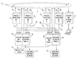
- FIG. 1 is a simplified schematic diagram of a protection system in accordance with the invention in block form.
- FIGS. 2A, 2 B and 2 C when placed side by side form a schematic diagram of the system of FIG. 1 in pertinent detail.
- FIG. 3 is a schematic diagram of the reactor trip breaker circuit of the system shown in FIG. 1 .
- FIG. 4 is a schematic diagram of a partial protection signal indication and protection function indication circuit for the reactor trip function which forms part of the process protection system of the invention.
- FIG. 5 is a schematic diagram of a similar indicator system for the emergency safety functions which form part of the process protection system of the invention.
- the invention is directed to a protection system for a complex process and will be described as applied to a nuclear reactor. However, it will be evident to those skilled in the art that it has application to other types of complex processes.
- FIG. 1 provides an architectural overview of the process protection system 1 of the invention.
- the system includes a plurality of redundant process protection sets, in this case four protection sets, 3 1 - 3 4 .
- Each process protection set receives inputs (not shown) from the process, in this case a nuclear reactor, and processes these inputs to generate, as needed, partial protection signals.
- Partial protection signals include partial trip signals and partial safeguard actuation signals.
- the partial protection signals generated by the protection sets 3 1 - 3 4 are provided to the two voting logic trains 5 A and 5 B.
- Each of the voting logic trains 5 A and 5 B includes a reactor trip train 7 A and 7 B, and a safeguard actuation train 9 A and 9 B, respectively.
- Each of the train sections 7 A, 7 B, 9 A and 9 B receive the corresponding partial reactor trip and partial safeguard actuation signals from each of the process protection sets 3 1 - 3 4 through optic fiber data links 11 1 - 11 4 .
- Each of the reactor trip voting logic trains 7 A and 7 B vote on the partial signals received from the process protection sets in a manner to be discussed in more detail.
- the train trip signals generated by the voting logic trains are applied to an output device in the form of a reactor trip breaker circuit 13 .
- the safeguard actuation train signals generated by the two voting logic trains are applied to safeguard component actuators 15 .
- This four process channel set, two logic train architecture generally follows the organization of the existing process protection systems (analog, relay or solid state) that it is designed to replace. This approach supports the task of analyzing the system for conformance to the original design bases of the plant being upgraded. It also supports the ability to upgrade portions of the safety system at separate times.
- the system of FIG. 1 also includes an information network 17 which gathers information over transceiver cables 19 1 - 19 8 .
- a bridge 21 links these two networks to a plant-wide network (not shown) containing human-machine interfaces (HMI) 23 such as workstations.
- HMI human-machine interfaces
- the process protection sets 3 1 - 3 4 , the voting logic trains 5 A and 5 B, the reactor trip circuit 13 , the safeguard actuation component actuators 15 and the information network system 17 are all safety related.
- the HMI 23 is not safety related and the network connection to the bridge 21 provides the proper isolation between safety and non-safety components.
- FIGS. 2A, 2 B and 2 C when placed side by side, illustrate in more detail the process protection system of FIG. 1 .
- each of the process protection sets 3 1 - 3 4 includes a pair of microprocessor-based controllers 25 a , 25 b .
- the controllers 25 a and 25 b are preferably functionally diverse.
- Each of the controllers 25 a and 25 b includes input modules 27 , a processor 29 , output modules 31 , a data highway controller (DHC) 33 and a data link controller (DLC) 35 .
- DHC data highway controller
- DLC data link controller
- the microprocessor-based controllers 25 a and 25 b of the protection sets 3 1 - 3 4 receive inputs from a variety of sensors and transducers 37 distributed throughout the reactor system. These raw sensor signals are output through an isolator 39 for use for instance by a control system (not shown).
- the controllers 25 a and 25 b process the sensors/transducer signals, and for some functions perform calculations utilizing one or more of the sensed parameters. For some abnormal states of the process, there are primary and secondary calculations which can detect abnormal conditions. In these situations, the primary calculation is made in one of the controllers 25 a or 25 b of the protection set, and the secondary calculation is made in the other. Some of the calculated parameters are used by the control system and are provided by the output board 31 through an isolator 41 .
- Each of the controllers 25 a and 25 b generates both partial trip and safeguard actuation protection signals.
- the trip trains 7 A and 7 B of the voting logic trains 5 A and 5 B each include a pair of redundant microprocessor-based controllers 25 a and 25 b like the microprocessor-based controllers in the process protection sets 3 1 - 3 4 .
- the safeguard actuation trains 9 A and 9 B of the voting logic trains 5 A and 5 B also each include redundant microprocessor-based controllers 25 a and 25 b .
- Each of the microprocessors 25 a and 25 b of the process protection sets 3 1 - 3 4 transmits through its data link controller 35 the partial reactor trip protection signals it has generated to each of the controllers 25 a and 25 b of each of the reactor trip train 7 A and 7 B over the associated optic fiber data link 11 1 a - 11 4 b .
- Each of these protection set controllers 25 a and 25 b also transmit each of their safeguard actuation protection signals through their data link controller 35 to the data link controllers of the microprocessor-based controllers 25 a and 25 b of each of the ESF trains 9 A and 9 B over the associated fiber optic data link 11 .
- the pairs of microprocessor-based controllers 25 a and 25 b and the two voting logic trains 5 A and 5 B receive partial reactor trip signals from each of the eight microprocessor-based controllers in the four process protection sets.
- the pairs of microprocessor-based controllers in each of the safeguard actuation trains 9 A and 9 B receive the partial actuation signals from all eight of the protection set controllers.
- the processors 29 in each of the controllers of the trip trains 7 A and 7 B serve as voting processors which vote on the received partial trip signals.
- each voting processor receives partial trip signals from all eight protection set controllers
- the two controllers, 25 a and 25 b , in each protection set 3 1 - 3 4 generate partial trip signals on different conditions, so that the voting processors receive sets of four redundant signals for each trip function, one from each protection set.
- the voting processors then apply predetermined voting logic to the redundant sets of trip signals, such as ⁇ fraction (2/4) ⁇ , 2 ⁇ 3 and 1 ⁇ 2.
- the voting logic applied can change when a protection set is taken out of service for maintenance or test.
- some less critical functions may be performed only by two or three of the protection sets. If the predetermined number of partial reactor trip signals are detected by a voting processor, that voting logic controller will generate a function trip signal.
- Each voting logic controller separately applies its voting logic to the partial reactor trip signals for each reactor trip function with the results being ORed, so that if any reactor trip function satisfies the voting logic, an intermediate trip signal will be generated.
- the intermediate trip signals from the two voting logic controllers in each reactor trip train 7 A and 7 B are processed by AND logic 43 A and 43 B to generate a train reactor trip signal only if both controllers in the trip train generate an intermediate trip signal.
- the partial safeguard actuation signals from the eight controllers in the process protection sets 3 1 - 3 4 are applied to each of the safeguard actuation controllers in the safeguard actuation trains 9 A and 9 B.
- the two safeguard actuation controllers 25 a and 25 b in each protection set generate different partial safeguard actuation signals, so there are at most four redundant partial safeguard actuation signals for any given function.
- the voting processors in the voting logic controllers of the safeguard actuation trains also apply predetermined ⁇ fraction (2/4) ⁇ , 2 ⁇ 3 and 1 ⁇ 2 voting logic as appropriate to generate intermediate safeguard actuation signals.
- the voting processors vote separately on the partial safeguard actuation signals for each safeguard function, with an intermediate safeguard actuation signal being generated if any safeguard actuation function satisfies the voting logic.
- the intermediate safeguard actuation signals from the pair of voting logic controllers in each safeguard train are processed by AND logic 45 A and 45 B to produce train safeguard actuation signals when intermediate signals are generated by each controller in the pair.
- FIGS. 2A-2C also illustrate in more detail the information network system 17 .
- this system includes two fiber-optic networks 47 A and 47 B.
- the two controllers of each of the protection sets 3 1 and 3 3 each are connected to the A network 47 A by the transceiver cables 19 1 and 19 3 through fiber-optic transceivers 49 1 and 49 3 .
- the two controllers in each of the protection sets 3 2 and 3 4 are connected to the B fiber-optic safety network 47 B by the transceiver cables 19 2 and 19 4 through the fiber-optic transceivers 49 2 and 49 4 .
- the two fiber-optic networks 47 A and 47 B are linked through isolators 50 A and 50 B to the bridge 21 incorporated in a work station 23 .
- the work station 23 is not safety related, while the information network system 17 , together with the remainder of the system shown in FIGS. 2A-2C is safety related.
- the isolators 50 provide the required isolation between the safety and non-safety portions of the overall system.
- Each of the fiber-optic nets 47 A and 47 B also receives information from each of the controllers in the reactor trip trains and the safeguard actuation trains, through additional transceiver cables 19 5 - 19 8 and additional fiber optic transceivers 49 5 - 49 8 .
- FIG. 3 illustrates a reactor trip breaker circuit 13 which forms one output device for the protection system.
- the reactor trip circuit 13 is implemented by a pair of trip circuit breakers 51 A and 51 B connected in series between the power source 53 and the control rod drive mechanism (CRDM) 55 . Normally, both circuit breakers 51 A and 51 B are closed, so that the CRDM 55 is energized.
- the circuit breakers 51 A and 51 B are controlled by the reactor trip trains 7 A and 7 B. If AND logic 43 A or 43 B of either of the reactor trip trains 7 A or 7 B generates a train reactor trip signal, the corresponding train circuit breaker is opened to de-energize the CRDM 55 , thereby tripping the reactor.
- the train reactor trip signals are ORed in the reactor trip circuit 13 , so that the reactor is tripped if either train generates a train trip signal. This O-ring of the train trip signals assures that the reactor will be protected despite a single failure.
- Each of the trip circuit breakers 51 A and 51 B are shunted by a bypass circuit breaker 57 A or 57 B which permits the associated train to be taken out of service for maintenance or test.
- the train safeguard actuation signals generated by the safeguard actuation trains 9 A and 9 B separately operate separate safeguard components such that the safeguard function is carried out in response to a safeguard actuation signal for that function from either train 9 A or 9 B.
- the protection system 1 also includes an indicator system which provides indication to the operator of the status of the protection system. This includes indications of function partial reactor trip signals, as well as corresponding function trip signals.
- FIG. 4 illustrates the additional indicator logic 67 providing the indicator function for the reactor trip train. For each reactor trip function, the partial trip signals generated by each protection set for the two controllers in the trip train 7 A are applied through isolators 69 to an AND logic 71 A, while the partial trip signals for the train 7 B are also applied through isolators 69 to an AND logic 71 B. The resulting signals are then ORed by the logic 73 to drive the indicators for that protection set's partial trip for the given reactor trip function.
- Typical channel partial trip indicators include status lights 75 , an annunciator 77 and a computer point 79 , such as in the plant computer system (not shown).
- a partial trip indicator for a particular protection set for a specific reactor trip function is only generated when partial reactor trip signals from that protection set for that protection function have been applied to both voting logic controllers in at least one of the two independent and redundant logic trains. Similar indicators are provided for the three partial trip signals generated by each of the other protection sets for each of the trip functions.
- function specific reactor trip signals generated by the controllers in the trip train 7 A are passed through isolators 69 and ANDed at 81 A, while the corresponding signals from the B train are ANDed at 81 B. Again, the resulting signals are ORed at 83 and used to drive an indicator, such as a reactor trip anunciator output 85 or another computer point 87 .
- the isolators 69 are required to isolate the non-safety related indicators from the safety related voting logic. Thus, for each reactor trip function an indicator is actuated only when both voting processors in at least one of the two logic trains generate a function specific intermediate reactor trip signal.
- Similar indicators are provided for the safeguard functions by the additional logic 89 , illustrated in FIG. 5 .
- the function partial safeguard actuation signals for each function input by a protection set to the pair of voting logic controllers in each safeguard actuation train 9 A and 9 B are passed through isolators 69 and ANDed at 91 A and 91 B, respectively, with the results ORed at 93 to drive an indicator such as 95 , 97 or 99 .
- an indicator such as 95 , 97 or 99 .
- a similar set of indicators is provided for the three partial safeguard actuation signals generated by each protection set for each of the other partial safeguard actuations.
- the function specific safeguard signals voted by the pair of controllers in each of the safeguard trains 9 A and 9 B are passed through isolators 69 and ANDed at 101 A and 101 B, respectively, with the results ORed at 103 to drive a function actuation indication, 105 or 107 .
- the signals driving the indicators are first ANDed within the channels to reduce the spurious indications, and then ORed to reduce the effects of a single failure, just like the reactor trip and safeguard actuation signals.
Abstract
Description
Claims (7)
Priority Applications (4)
| Application Number | Priority Date | Filing Date | Title |
|---|---|---|---|
| US09/501,804 US6532550B1 (en) | 2000-02-10 | 2000-02-10 | Process protection system |
| SE0100201A SE521926C2 (en) | 2000-02-10 | 2001-01-24 | Protection system applying voice logic to a complex process |
| ES200100204A ES2189620B2 (en) | 2000-02-10 | 2001-01-30 | PROTECTION SYSTEM FOR PROCESS. |
| JP2001035950A JP2001296383A (en) | 2000-02-10 | 2001-02-13 | Process protection system |
Applications Claiming Priority (1)
| Application Number | Priority Date | Filing Date | Title |
|---|---|---|---|
| US09/501,804 US6532550B1 (en) | 2000-02-10 | 2000-02-10 | Process protection system |
Publications (1)
| Publication Number | Publication Date |
|---|---|
| US6532550B1 true US6532550B1 (en) | 2003-03-11 |
Family
ID=23995091
Family Applications (1)
| Application Number | Title | Priority Date | Filing Date |
|---|---|---|---|
| US09/501,804 Expired - Lifetime US6532550B1 (en) | 2000-02-10 | 2000-02-10 | Process protection system |
Country Status (4)
| Country | Link |
|---|---|
| US (1) | US6532550B1 (en) |
| JP (1) | JP2001296383A (en) |
| ES (1) | ES2189620B2 (en) |
| SE (1) | SE521926C2 (en) |
Cited By (20)
| Publication number | Priority date | Publication date | Assignee | Title |
|---|---|---|---|---|
| US20040098140A1 (en) * | 2002-11-20 | 2004-05-20 | Richard Hess | High integrity control system architecture using digital computing platforms with rapid recovery |
| US20050278053A1 (en) * | 2004-05-26 | 2005-12-15 | Taiwan Semiconductor Manufacturing Co., Ltd. | Semiconductor manufacturing fault detection and management system and method |
| US20050278567A1 (en) * | 2004-06-15 | 2005-12-15 | Honeywell International Inc. | Redundant processing architecture for single fault tolerance |
| US7047553B1 (en) * | 2000-10-05 | 2006-05-16 | Arris International, Inc. | Method and apparatus for decreasing cable installation time and cable installation faults |
| US20080152066A1 (en) * | 2006-12-21 | 2008-06-26 | Randall Howard Jacobs | Protection systems for and methods of operating nuclear boiling water reactors |
| US20100222943A1 (en) * | 2009-02-10 | 2010-09-02 | Airbus Operations (S.A.S.) | Flight control system and aircraft comprising it |
| CN102522821A (en) * | 2011-12-01 | 2012-06-27 | 许继集团有限公司 | Intelligent terminal equipment in intelligent transformer substation and control method thereof |
| US20130103350A1 (en) * | 2011-04-07 | 2013-04-25 | The University Of Western Ontario | Method and system to validate wired sensors |
| US20130136222A1 (en) * | 2010-08-12 | 2013-05-30 | Mitsubishi Heavy Industries, Ltd. | Control system for plant |
| US20130179727A1 (en) * | 2012-01-07 | 2013-07-11 | Compunetix, Inc. | Reliable compute engine, method and apparatus |
| US20130178955A1 (en) * | 2012-01-05 | 2013-07-11 | International Business Machines Corporation | Apparatus safeguard |
| US8769360B2 (en) | 2010-10-14 | 2014-07-01 | International Business Machines Corporation | Dynamic detection and identification of the functional state of multi-processor cores |
| WO2015112304A3 (en) * | 2013-12-31 | 2015-10-29 | Nuscale Power, Llc | Nuclear reactor protection systems and methods |
| WO2017049124A1 (en) * | 2015-09-16 | 2017-03-23 | Profire Energy, Inc. | Distributed networking system and method |
| US9983551B2 (en) | 2010-06-17 | 2018-05-29 | International Business Machines Corporation | Intelligent switching |
| US9997265B2 (en) * | 2015-03-27 | 2018-06-12 | Mitsubishi Electric Power Products, Inc. | Safety system for a nuclear power plant and method for operating the same |
| US10432754B2 (en) | 2015-09-16 | 2019-10-01 | Profire Energy, Inc | Safety networking protocol and method |
| CN110366760A (en) * | 2016-12-30 | 2019-10-22 | 纽斯高动力有限责任公司 | Reactor protective system and method |
| US10514683B2 (en) | 2015-09-16 | 2019-12-24 | Profire Energy, Inc. | Distributed networking system and method to implement a safety state environment |
| US11961625B2 (en) * | 2021-03-01 | 2024-04-16 | Nuscale Power, Llc | Nuclear reactor protection systems and methods |
Families Citing this family (5)
| Publication number | Priority date | Publication date | Assignee | Title |
|---|---|---|---|---|
| DE60225443T2 (en) * | 2001-05-31 | 2009-03-26 | Omron Corp. | SECURITY UNIT, CONTROL CHAIN PROCEDURE, CONTROL SYSTEM CONTROL METHOD, AND CONTROL SYSTEM MONITORING PROCESS |
| US7120505B2 (en) * | 2001-06-22 | 2006-10-10 | Omron Corporation | Safety network system, safety slave, and safety controller |
| KR100875467B1 (en) | 2006-12-05 | 2008-12-22 | 한국원자력연구원 | Digital Reactor Protection System with Independent Redundancy Structure Redundancy |
| CN102426863B (en) * | 2011-10-31 | 2015-12-16 | 中广核工程有限公司 | Nuclear power plant reactor shutdown signal transmission system and method |
| KR101960020B1 (en) * | 2017-12-11 | 2019-03-19 | 한국전력기술 주식회사 | Plant Protection System and Reactor Trip Switchgear System |
Citations (8)
| Publication number | Priority date | Publication date | Assignee | Title |
|---|---|---|---|---|
| US4583224A (en) * | 1982-11-08 | 1986-04-15 | Hitachi, Ltd. | Fault tolerable redundancy control |
| US4622667A (en) * | 1984-11-27 | 1986-11-11 | Sperry Corporation | Digital fail operational automatic flight control system utilizing redundant dissimilar data processing |
| US4687623A (en) * | 1985-10-31 | 1987-08-18 | Westinghouse Electric Corp. | Self-compensating voted logic power interface with tester |
| US4804515A (en) | 1984-10-31 | 1989-02-14 | Westinghouse Electric Corp. | Distributed microprocessor based sensor signal processing system for a complex process |
| US5394409A (en) * | 1991-07-22 | 1995-02-28 | Siemens Aktiengesellschaft | Method of detecting and localizing errors in redundant primary detectors of an automation system |
| US6049578A (en) * | 1997-06-06 | 2000-04-11 | Abb Combustion Engineering Nuclear Power, Inc. | Digital plant protection system |
| US6253348B1 (en) * | 1997-06-06 | 2001-06-26 | Telefonaktiebolaget Lm Ericsson (Publ) | Hardware design for majority voting, and testing and maintenance of majority voting |
| US6367031B1 (en) * | 1998-12-17 | 2002-04-02 | Honeywell International Inc. | Critical control adaption of integrated modular architecture |
-
2000
- 2000-02-10 US US09/501,804 patent/US6532550B1/en not_active Expired - Lifetime
-
2001
- 2001-01-24 SE SE0100201A patent/SE521926C2/en not_active IP Right Cessation
- 2001-01-30 ES ES200100204A patent/ES2189620B2/en not_active Expired - Fee Related
- 2001-02-13 JP JP2001035950A patent/JP2001296383A/en active Pending
Patent Citations (8)
| Publication number | Priority date | Publication date | Assignee | Title |
|---|---|---|---|---|
| US4583224A (en) * | 1982-11-08 | 1986-04-15 | Hitachi, Ltd. | Fault tolerable redundancy control |
| US4804515A (en) | 1984-10-31 | 1989-02-14 | Westinghouse Electric Corp. | Distributed microprocessor based sensor signal processing system for a complex process |
| US4622667A (en) * | 1984-11-27 | 1986-11-11 | Sperry Corporation | Digital fail operational automatic flight control system utilizing redundant dissimilar data processing |
| US4687623A (en) * | 1985-10-31 | 1987-08-18 | Westinghouse Electric Corp. | Self-compensating voted logic power interface with tester |
| US5394409A (en) * | 1991-07-22 | 1995-02-28 | Siemens Aktiengesellschaft | Method of detecting and localizing errors in redundant primary detectors of an automation system |
| US6049578A (en) * | 1997-06-06 | 2000-04-11 | Abb Combustion Engineering Nuclear Power, Inc. | Digital plant protection system |
| US6253348B1 (en) * | 1997-06-06 | 2001-06-26 | Telefonaktiebolaget Lm Ericsson (Publ) | Hardware design for majority voting, and testing and maintenance of majority voting |
| US6367031B1 (en) * | 1998-12-17 | 2002-04-02 | Honeywell International Inc. | Critical control adaption of integrated modular architecture |
Non-Patent Citations (1)
| Title |
|---|
| Preckshot, G.G., "Method for Performing Diversity and Defense-in-Depth Analyses of Reactor Protection Systems", 12/94, pp. i-viii, l-35, UCRL-ID-119239, FESSP, Lawrence Livermore National Laboratory, Livermore, CA. |
Cited By (41)
| Publication number | Priority date | Publication date | Assignee | Title |
|---|---|---|---|---|
| US7047553B1 (en) * | 2000-10-05 | 2006-05-16 | Arris International, Inc. | Method and apparatus for decreasing cable installation time and cable installation faults |
| US6813527B2 (en) * | 2002-11-20 | 2004-11-02 | Honeywell International Inc. | High integrity control system architecture using digital computing platforms with rapid recovery |
| US20040098140A1 (en) * | 2002-11-20 | 2004-05-20 | Richard Hess | High integrity control system architecture using digital computing platforms with rapid recovery |
| US20050278053A1 (en) * | 2004-05-26 | 2005-12-15 | Taiwan Semiconductor Manufacturing Co., Ltd. | Semiconductor manufacturing fault detection and management system and method |
| US7089072B2 (en) * | 2004-05-26 | 2006-08-08 | Taiwan Semiconductor Manufacturing Company, Ltd. | Semiconductor manufacturing fault detection and management system and method |
| US20050278567A1 (en) * | 2004-06-15 | 2005-12-15 | Honeywell International Inc. | Redundant processing architecture for single fault tolerance |
| US7392426B2 (en) * | 2004-06-15 | 2008-06-24 | Honeywell International Inc. | Redundant processing architecture for single fault tolerance |
| US7912170B2 (en) | 2006-12-21 | 2011-03-22 | General Electric Company | Protection systems for nuclear boiling water reactors |
| US20080152066A1 (en) * | 2006-12-21 | 2008-06-26 | Randall Howard Jacobs | Protection systems for and methods of operating nuclear boiling water reactors |
| US7634043B2 (en) | 2006-12-21 | 2009-12-15 | General Electric Company | Protection systems for and methods of operating nuclear boiling water reactors |
| US20100091928A1 (en) * | 2006-12-21 | 2010-04-15 | Randall Howard Jacobs | Protection systems for nuclear boiling water reactors |
| US20100222943A1 (en) * | 2009-02-10 | 2010-09-02 | Airbus Operations (S.A.S.) | Flight control system and aircraft comprising it |
| US8761969B2 (en) * | 2009-02-10 | 2014-06-24 | Airbus Operations S.A.S. | Flight control system and aircraft comprising it |
| US10168670B2 (en) | 2010-06-17 | 2019-01-01 | International Business Machines Corporation | Intelligent switching |
| US9983551B2 (en) | 2010-06-17 | 2018-05-29 | International Business Machines Corporation | Intelligent switching |
| US20130136222A1 (en) * | 2010-08-12 | 2013-05-30 | Mitsubishi Heavy Industries, Ltd. | Control system for plant |
| US9558856B2 (en) * | 2010-08-12 | 2017-01-31 | Mitsubishi Heavy Industries, Ltd. | Control system for plant |
| US8769360B2 (en) | 2010-10-14 | 2014-07-01 | International Business Machines Corporation | Dynamic detection and identification of the functional state of multi-processor cores |
| US20130103350A1 (en) * | 2011-04-07 | 2013-04-25 | The University Of Western Ontario | Method and system to validate wired sensors |
| US9280516B2 (en) * | 2011-04-07 | 2016-03-08 | The University Of Western Ontario | Method and system to validate wired sensors |
| CN102522821B (en) * | 2011-12-01 | 2015-01-07 | 许继电气股份有限公司 | Intelligent terminal equipment in intelligent transformer substation and control method thereof |
| CN102522821A (en) * | 2011-12-01 | 2012-06-27 | 许继集团有限公司 | Intelligent terminal equipment in intelligent transformer substation and control method thereof |
| US20130178955A1 (en) * | 2012-01-05 | 2013-07-11 | International Business Machines Corporation | Apparatus safeguard |
| US9037283B2 (en) * | 2012-01-05 | 2015-05-19 | International Business Machines Corporation | Apparatus safeguard |
| US8856590B2 (en) * | 2012-01-07 | 2014-10-07 | Compunetix, Inc. | Reliable compute engine, method and apparatus |
| US20130179727A1 (en) * | 2012-01-07 | 2013-07-11 | Compunetix, Inc. | Reliable compute engine, method and apparatus |
| EP3090433A4 (en) * | 2013-12-31 | 2016-12-14 | Nuscale Power Llc | Nuclear reactor protection systems and methods |
| WO2015112304A3 (en) * | 2013-12-31 | 2015-10-29 | Nuscale Power, Llc | Nuclear reactor protection systems and methods |
| CN106165020A (en) * | 2013-12-31 | 2016-11-23 | 纽斯高动力有限责任公司 | Reactor protective system and method |
| US11728051B2 (en) * | 2013-12-31 | 2023-08-15 | Nuscale Power, Llc | Nuclear reactor protection systems and methods |
| US11017907B2 (en) * | 2013-12-31 | 2021-05-25 | Nuscale Power, Llc | Nuclear reactor protection systems and methods |
| EP3274997A4 (en) * | 2015-03-27 | 2018-11-21 | Mitsubishi Electric Power Products, Inc. | Safety system for a nuclear power plant and method for operating the same |
| US9997265B2 (en) * | 2015-03-27 | 2018-06-12 | Mitsubishi Electric Power Products, Inc. | Safety system for a nuclear power plant and method for operating the same |
| US10992787B2 (en) | 2015-09-16 | 2021-04-27 | Profire Energy, Inc. | Safety networking protocol and method |
| US10514683B2 (en) | 2015-09-16 | 2019-12-24 | Profire Energy, Inc. | Distributed networking system and method to implement a safety state environment |
| US10432754B2 (en) | 2015-09-16 | 2019-10-01 | Profire Energy, Inc | Safety networking protocol and method |
| US11314235B2 (en) | 2015-09-16 | 2022-04-26 | Profire Energy, Inc. | Systems to implement a safety state environment among control modules |
| WO2017049124A1 (en) * | 2015-09-16 | 2017-03-23 | Profire Energy, Inc. | Distributed networking system and method |
| CN110366760A (en) * | 2016-12-30 | 2019-10-22 | 纽斯高动力有限责任公司 | Reactor protective system and method |
| US20210287813A1 (en) * | 2016-12-30 | 2021-09-16 | Nuscale Power, Llc | Nuclear reactor protection systems and methods |
| US11961625B2 (en) * | 2021-03-01 | 2024-04-16 | Nuscale Power, Llc | Nuclear reactor protection systems and methods |
Also Published As
| Publication number | Publication date |
|---|---|
| SE0100201L (en) | 2001-08-11 |
| ES2189620A1 (en) | 2003-07-01 |
| SE521926C2 (en) | 2003-12-16 |
| SE0100201D0 (en) | 2001-01-24 |
| ES2189620B2 (en) | 2007-05-16 |
| JP2001296383A (en) | 2001-10-26 |
Similar Documents
| Publication | Publication Date | Title |
|---|---|---|
| US6532550B1 (en) | Process protection system | |
| JP7203154B2 (en) | Reactor protection system and how to operate it | |
| KR102642462B1 (en) | Nuclear reactor protection systems and methods | |
| US5984504A (en) | Safety or protection system employing reflective memory and/or diverse processors and communications | |
| KR100808787B1 (en) | Plant Protection System | |
| US20180211734A1 (en) | Reactor protection-processor-to-reactor-trip breaker interface and method for operating the same | |
| JP4128083B2 (en) | Digital reactor protection system that eliminates common software type failures | |
| US20110313580A1 (en) | Method and platform to implement safety critical systems | |
| CN106340332A (en) | Nuclear power station digital protection control system | |
| KR20080013153A (en) | Digital security system for nuclear power plant | |
| US10541059B2 (en) | Digital protection system for nuclear power plant | |
| Chen et al. | Failure Mechanism Traceability and Application in Human System Interface of Nuclear Power Plants using RESHA | |
| CA2304438C (en) | Safety or protection system employing reflective memory and/or diverse processors and communications | |
| Kabra et al. | Dependability analysis of proposed I&C architecture for safety systems of a large PWR | |
| Yang et al. | Research and Analysis on 1E Distributed Control System Priority Logic Module | |
| Moutrey et al. | Sizewell B power station primary protection system design application overview | |
| Hickling | Ergonomics and engineering aspects of designing an alarm system for a modern nuclear power plant | |
| CN116598032A (en) | Digital protection system of nuclear power plant based on FPGA | |
| Shirasawa et al. | Digital I&C System in the US-APWR | |
| Chung et al. | Design of advanced power reactor (APR1400) I&C system | |
| Bagnasco et al. | REQUIREMENTS AND DESIGN FOR A | |
| Tooley et al. | Dynamic testing of the primary protection system (at Sizewell B) | |
| Cobb et al. | CIL's experience with a computerized ammonia plant trip system | |
| Kim et al. | Design Approach of Control System for Advanced Nuclear Power Plant | |
| Martin | The Use and Assessment of Programmable Safety Systems on a Nuclear Fuel Reprocessing Plant |
Legal Events
| Date | Code | Title | Description |
|---|---|---|---|
| AS | Assignment |
Owner name: WESTINGHOUSE ELECTRIC CO. LLC, PENNSYLVANIA Free format text: ASSIGNMENT OF ASSIGNORS INTEREST;ASSIGNORS:CREW, ALBERT W.;GHRIST, WILLIAM D.;VITALBO, CARL A.;AND OTHERS;REEL/FRAME:010603/0351;SIGNING DATES FROM 20000204 TO 20000207 |
|
| STCF | Information on status: patent grant |
Free format text: PATENTED CASE |
|
| FPAY | Fee payment |
Year of fee payment: 4 |
|
| FPAY | Fee payment |
Year of fee payment: 8 |
|
| FPAY | Fee payment |
Year of fee payment: 12 |
|
| AS | Assignment |
Owner name: CREDIT SUISSE AG, CAYMAN ISLANDS BRANCH, AS COLLATERAL AGENT, NEW YORK Free format text: SECURITY INTEREST;ASSIGNORS:WESTINGHOUSE ELECTRIC COMPANY LLC;FAUSKE AND ASSOCIATES LLC;REEL/FRAME:046708/0222 Effective date: 20180801 Owner name: GOLDMAN SACHS BANK USA, AS COLLATERAL AGENT, NEW YORK Free format text: SECURITY INTEREST;ASSIGNORS:WESTINGHOUSE ELECTRIC COMPANY LLC;FAUSKE AND ASSOCIATES LLC;REEL/FRAME:046708/0332 Effective date: 20180801 Owner name: BANK OF MONTREAL, AS ADMINISTRATIVE AGENT, ILLINOIS Free format text: SECURITY INTEREST;ASSIGNORS:WESTINGHOUSE ELECTRIC COMPANY LLC;FAUSKE AND ASSOCIATES LLC;REEL/FRAME:046708/0639 Effective date: 20180801 Owner name: CREDIT SUISSE AG, CAYMAN ISLANDS BRANCH, AS COLLAT Free format text: SECURITY INTEREST;ASSIGNORS:WESTINGHOUSE ELECTRIC COMPANY LLC;FAUSKE AND ASSOCIATES LLC;REEL/FRAME:046708/0222 Effective date: 20180801 Owner name: GOLDMAN SACHS BANK USA, AS COLLATERAL AGENT, NEW Y Free format text: SECURITY INTEREST;ASSIGNORS:WESTINGHOUSE ELECTRIC COMPANY LLC;FAUSKE AND ASSOCIATES LLC;REEL/FRAME:046708/0332 Effective date: 20180801 Owner name: BANK OF MONTREAL, AS ADMINISTRATIVE AGENT, ILLINOI Free format text: SECURITY INTEREST;ASSIGNORS:WESTINGHOUSE ELECTRIC COMPANY LLC;FAUSKE AND ASSOCIATES LLC;REEL/FRAME:046708/0639 Effective date: 20180801 |
|
| AS | Assignment |
Owner name: WESTINGHOUSE ELECTRIC COMPANY LLC, PENNSYLVANIA Free format text: RELEASE OF SECURITY INTEREST IN PATENTS;ASSIGNOR:GOLDMAN SACHS BANK USA, AS COLLATERAL AGENT;REEL/FRAME:049937/0032 Effective date: 20190801 Owner name: FAUSKE AND ASSOCIATES LLC, ILLINOIS Free format text: RELEASE OF SECURITY INTEREST IN PATENTS;ASSIGNOR:GOLDMAN SACHS BANK USA, AS COLLATERAL AGENT;REEL/FRAME:049937/0032 Effective date: 20190801 |
|
| AS | Assignment |
Owner name: FAUSKE AND ASSOCIATES LLC, ILLINOIS Free format text: RELEASE OF SECURITY INTEREST IN PATENTS;ASSIGNOR:CREDIT SUISSE AG, CAYMAN ISLANDS, AS COLLATERAL AGENT;REEL/FRAME:066380/0392 Effective date: 20240125 Owner name: WESTINGHOUSE ELECTRIC COMPANY LLC, PENNSYLVANIA Free format text: RELEASE OF SECURITY INTEREST IN PATENTS;ASSIGNOR:CREDIT SUISSE AG, CAYMAN ISLANDS, AS COLLATERAL AGENT;REEL/FRAME:066380/0392 Effective date: 20240125 |